pregasi consegnarel'inserto manuale d'uso … · presence of our product on the market....
TRANSCRIPT

1
24 M W TOP U/IT24 MS W TOP U/IT
AZIENDA CERTIFICATA ISO 9001
MANUALE DIINSTALLAZIONE EMANUTENZIONE
INSTALLATIONAND MAINTENANCE
MANUAL
MANUAL PARALA INSTALACIÓN Y
EL MANTENIMIENTO
MANUAL DEINSTALAÇÃO EMANUTENÇÃO
PREGASI CONSEG
NARE
L'INSERTO
"MANUALE D
'USO"
AL SIG. U
TENTE
PLEASE M
AKE SURE T
HAT THE
"USE MANUAL" I
S HANDED
OVER TO TH
E USER
TENGAN LA
AMABILIDAD DE
ENTREG
ARLE AL U
SUARIO EL
"MANUAL D
E USO"
FAVOR ENTREG
AR O
"MANUAL D
E USO"
AO SR. UTEN
TE
CALDAIA MURALE A GAS TERMO - ALTO RENDIMENTO - MODULANTEWALL-HUNG GAS BOILER FOR HEATING - HIGH EFFICIENCY - MODULATING
CALDERA MURAL A GAS PARA CALEFACCIÓN - ALTO RENDIMIENTO - MODULANTECALDEIRA DE PAREDE A GÁS PARA CALEFACÇÃO - ALTO RENDIMENTO - MODULANTE

�7
Readcarefullyallwarningandinstructionscontainedinthismanualattheygiveimportantsafety instructions regarding installation and maintenance. Keep this manual for futurereference.Installationmustbecarriedoutbyqualifiedpersonnelwhowillberesponsibleforrespectingexistingsafetyregulations.
GB

32
Congratulations...... on an excellent choice.
We thank you for the preference accorded to our products.LAMBORGHINI CALORECLIMA has been actively present in Italy and throughout the world since1959 with a widespread network of agents and concessionary agents to constantly guarantee thepresence of our product on the market. Alongside this is the support of a technical service,“LAMBORGHINI SERVICE”, which is entrusted with the qualified servicing of the product.
For the installation and positioning of the boiler:CAREFULLY OBSERVE THE LOCAL REGULATIONS IN FORCE.
INDEX PAGE
GENERAL INSTRUCTIONS _____________________________________________ 33DESCRIPTION _______________________________________________________ 34MAIN COMPONENTS ________________________________________________ 35DIMENSIONS mm ____________________________________________________ 36TECHNICAL FEATURES ________________________________________________ 36GAS - NOZZLE CALIBRATION __________________________________________ 37ELECTRICAL CONNECTIONS - WIRING DIAGRAMS _______________________ 38MALFUNCTIONS AND ADJUSTMENTS __________________________________ 41WATER CONNECTION _______________________________________________ 42WATER CIRCUIT ______________________________________________________ 43INSTALLATION _______________________________________________________ 44START-UP ___________________________________________________________ 44FLUE EXHAUST CONNECTION _________________________________________ 45FLUE EXHAUST INSTALLATION _________________________________________ 47ADJUSTMENTS ______________________________________________________ 48SWITCHING OFF ____________________________________________________ 49MAINTENANCE _____________________________________________________ 49OPERATION WITH DIFFERENT TYPES OF GAS ____________________________ 51FAULT-FINDING CHART _______________________________________________ 52INSTALLATION OF XILO T BOILER WITH PAC HEATER ______________________ 53

33
GENERAL INSTRUCTIONS
● This booklet constitutes an integral and essential part of the product.Read carefully the instructions contained in this booklet as they provide important directions regarding thesafety of installation, use and maintenance. Preserve this booklet with care for any further consultation.The installation of the boiler must be carried out in compliance with current regulations, according to theinstructions of the manufacturer and by qualified personnel. An incorrect installation can cause injury ordamage to persons, animals and objects, for which the manufacturer cannot be held responsible.
● After removing the packaging materials, check the content integrity. In case of doubt, do not use the unitand contact the supplier. The packaging material (wooden crates, nails, clips, plastic bags, foam, etc.)must not be left within reach of children as they are potential sources of danger.
● This boiler is designed to heat water to a temperature below boiling (atmospheric pressure). It must beconnected to a heating system compatible with its performances and output.
● This appliance should be destined only for the use for which it has been expressly envisaged. Any otheruse is to be considered improper and therefore dangerous. The manufacturer cannot be consideredresponsible for any damages caused from improper or unreasonable use.
ALL INSTALLATION, MAINTENANCE AND GAS CONVERSION OPERATIONS MUST BE CARRIED OUT BYAUTHORISED SKILLED TECHNICIANS.
TO ENSURE THAT BOILER IS INSTALLED CORRECTLY AND THAT IT FUNCTIONS PROPERLY, WE RECOMMENDTHAT ONLY LAMBORGHINI ACCESSORIES AND SPARE PARTS BE USED.
ON NOTICING THE SMELL OF GAS DO NOT TOUCH ANY ELECTRIC SWITCH. OPEN DOORS AND WINDOWS.SHUT OFF THE GAS COCKS.
INSTALL THE BOILER ON WALLS WHICH ARE AS WIDE AS OR WIDER THAN THE BOILER ITSELF.

34
DESCRIPTION
These boilers are fully automatic and gas control is effected by an electronic control unit having the followingcharacteristics:
- Continuous modulation mode on heating circuit;- Possibility to adjust the heating output;- Possibility to adjust the slow ignition;- Possibility of being combined with a water heater.
The models are equipped with:
- No-water pressure switch;- Total safety thermostat;- High efficiency fume exchanger.
XILO T 24 M W TOPElectronic ignition and ionization flame control.Combustion and flue gas exhaust are of atmospheric type. It is equipped with flue gas exhaust control device(FLUE CONTROL).
FLUE CONTROL THERMOSTATThe XILO T 24 M boiler is fitted with the FLUE CONTROL thermostat for control of fume evacuation. Anincrease in fume temperature in the down-draught diverter indicates an anomaly in fume evacuation. TheFLUE CONTROL probe in the down-draught diverter detects variations in temperature and shuts down theboiler. Efficient operation of this safety system depends on observance of the following:- Do not deactivate the FLUE CONTROL thermostat.- Inspect the boiler and the flue immediately if the FLUE CONTROL device trips frequently.- If the FLUE CONTROL device is changed make sure you observe assembly and probe positioning instruc-
tions carefully and use only original LAMBORGHINI spare parts.If there is a fume evacuation anomaly act quickly to prevent the formation of Carbon Monoxide, a poisonousgas that causes intoxication and potentially fatal harm to both humans and animals.
XILO T 24 MS W TOPEquipped with electronic control unit for automatic ignition and ionization electrode flame control.To ensure safe operation, the electric fan is controlled by a pressure switch.Flue gas exhaust can be made by means of the following:
- a flue pipe concentric with the air intake pipe;- a double pipe, one for flue gas exhaust and the other for combustion air intake.

35
MAIN COMPONENTS
LEGEND
1 Fumes pressure switch2 Fan3 Heating sensor4 Total safety thermostat5 Exchanger6 Burner7 Ignition electrodes8 Control electrode9 Automatic air bleed valve10 Safety valve
11 No-water pressure switch12 Circulator13 Filling cock14 Gas valve15 Modulating coil16 Gas pressure reading point17 Expansion tank18 Thermohydrometer19 Malfunction warning light20 ON/OFF warning light
21 Lock-out warning light22 Hot water potentiometer (if any)23 Function selector24 Heating adjustment potentiometer25 Fume hood26 Flue control27 Heater circuit purging device
(if any)28 Taken combustion test
XILO T 24 M W TOP XILO T 24 MS W TOP
192021
1514
25
17
4
6
16
9
3
27
26
5
78
9
10
11
12
1318242321 2322
1514
1
17
4
6
16
9
3
27
2
5
78
9
10
11
12
13
28
1824
192021
Fume analysis points

36
DIMENSIONS mm
CIRCULATING PUMP FEATURESSystem delivery/pressure
100 Max. 3000 220
105
440
770
100 Max. 3000
160
330
Boiler version: mod. M type B11 BSmod. MS type C12-C32-C42-C52-C62-C82
Category: II 2H3+Cl NOx: 1 (M) - 2 (MS)
TECHNICAL FEATURES
XILO T 24 M W TOP XILO T 24 MS W TOP
220
440
770
160
330
152,5
MODELInput Output
Main SystemGas
Supply SupplykW kcal/h kW kcal/h Ø Ø Ø I kg
XILO T 24 MSW TOP
ReturnØkW kW kcal/h
Return
Heater
Ø
3/4”3/4” 3/4” 3/4” 3/4”
Thermal capacity Min. thermalcapacity
Connections
Expansiontank
Weight
Input Output
kcal/hXILO T 24 M
W TOP3/4”3/4” 3/4” 3/4” 3/4”
300 600 900 1200 1500 1800 2100 2400 2700 3000 3300 3600
600
500
400
300
200
100
Resi
dual
pre
ssur
em
bar
Delivery (l/h)
700
8 42
8 4014,1 12126 12,56 10804
25972 23633 27,48 14,1 11,9412126 10268
30,2 25972 27,54 23686
30,2
Operatingpressure
bar
3
3
Ø
1/2”
1/2”
Coldwaterinlet
Max. water temperature 90°CRated gas pressure: G20 20 mbar G30 28-30 mbar/G31 37 mbar

37
The boilers leave the factory calibrated and ready to operate with G20 (Natural Gas) and G30/G31 (LPG).
For proper calibration, see the table below:
BURNER PRESSURE CURVES - OUTPUT
GAS-NOZZLE CALIBRATION
XILO T 24 M XILO T 24 MS
Slow ignition adjustment3.5 mbar G20 (Natural Gas) (M) - 3 mbar G20 (Natural Gas) (MS)7.5 mbar G30/G31 (LPG) (M) - 8 mbar G30/G31 (LPG) (MS)
Jets pressure mbarGas type
G20 20 mbar(Natural Gas)
G30 28-30 mbar(LPG)
G31 37 mbar(LPG)
Burner jets
Ø mm.
1,25
0,77
0,77
L.C.V.
kcal/h
8.550
29.330
22.360
DeliveryXILO T 24 MSXILO T 24 M
m3/h
3,04
0,89
1,16
max.
12,5
26,8
34,5
2,2
6,5
8,5
min.max.
12,5
25,6
33
3
6,3
8,6
min.
10 kW
mbar
2,2
12,5
26,8
2515 20
10
5
12,5 G20
0
15
20
2526,8 G30
kPa
30 350
35
1
0,5
0
1,5
2
2,5
3
34,5 G31
0,1
3010
09D
IS13
61
8,5
6,5
34,5
10 kW
mbar
3
12,5
2515 20
10
5
12,5 G20
0
15
20
25 25,6 G30
kPa
30 350
35
1
0,5
0
1,5
2
2,5
3
33 33 G31
0,1
30
8,6
6,3
1009
DIS
1362
25,6

38
ELECTRICAL CONNECTIONS - WIRING DIAGRAMS
The boiler must be connected to an earthed, single-phase 230V-50 Hz mains supply by means of a three-wirecable, ensuring that connections to the PHASE and NEUTRAL terminals are made correctly.A bipolar switch must be used with contacts opening to at least 3 mm. The power lead must only be replacedby another with the following characteristics: “HAR H05 vv-F” 3 X 1.00 mm2. (You are strongly advised to useoriginal LAMBORGHINI accessories and spare parts only).
Installation must be made in compliance with safety REGULATIONS IN FORCE.Grounde connections are compulsory. Connect the boiler to an efficient grounding system.
To gain access to the electrical panel which houses the power supply terminal block and any connection to aroom thermostat, proceed as follows:
● Disconnect the boiler powersupply.
● Undo the two grating screws(fig. 1).
● Undo the two casing fixingscrews (fig. 2).
● Raise the casing and then pull ittowards you (fig. 3).
● To access electrical andelectronic parts loosen screws Aand pull the entire paneloutwards (fig. 4). Tiltdownwards and undo thescrews B on the cover C (fig. 5).
fig.3 fig.4
fig.1 fig.2
fig.5
A
A
B
c
Voltage
V
230
Frequency Absorbed powerkW
Hz
Noise leveldB (A)
50MS47
M52
Protectionindex
IPX 4D
MS0,153
M0,123
39
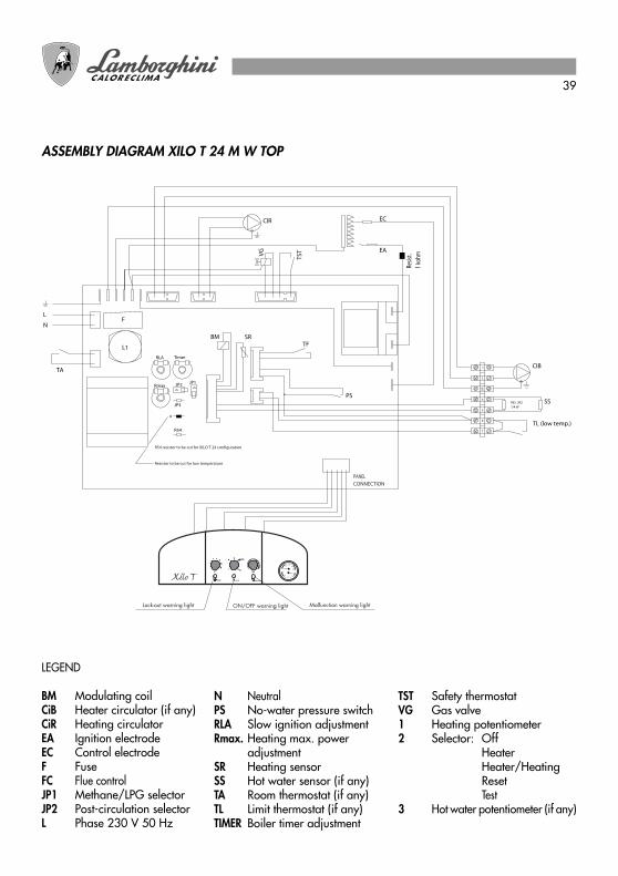
LEGEND
BM Modulating coilCiB Heater circulator (if any)CiR Heating circulatorEA Ignition electrodeEC Control electrodeF FuseFC Flue controlJP1 Methane/LPG selectorJP2 Post-circulation selectorL Phase 230 V 50 Hz
N NeutralPS No-water pressure switchRLA Slow ignition adjustmentRmax. Heating max. power
adjustmentSR Heating sensorSS Hot water sensor (if any)TA Room thermostat (if any)TL Limit thermostat (if any)TIMER Boiler timer adjustment
TST Safety thermostatVG Gas valve1 Heating potentiometer2 Selector: Off
HeaterHeater/HeatingResetTest
3 Hot water potentiometer (if any)
ASSEMBLY DIAGRAM XILO T 24 M W TOP
Resis
t.1
kohm
F
RES. 2K2
1/4 W
TL (low temp.)
TF
1
2
4
5
6
7
TSTVG
CIB
CIR
EA
EC
L
N
TA
Lock-out warning light ON/OFF warning light Malfunction warning light
PANELCONNECTION
SS
JP1JP2
JP3
BM SR
L1
R54
R54 resistor to be cut for XILO T 24 configuration
x
Resistor to be cut for low temperature
PS
Rmax
RLA Timer

40
ASSEMBLY DIAGRAM XILO T 24 MS W TOP
LEGEND
BM Modulating coilCiB Heater circulator (if any)CiR Heating circulatorEA Ignition electrodeEC Control electrodeF FuseJP1 Methane/LPG selectorJP2 Post-circulation selectorL Phase 230 V 50 HzN Neutral
PA Air pressure switchPS No-water pressure switchRLA Slow ignition adjustmentRmax. Heating max.
power adjustmentSR Heating sensorSS Hot water sensor (if any)TA Room thermostat (if any)TL Limit thermostat (if any)TIMER Boiler timer adjustment
TST Safety thermostatVG Gas valveVN Fan1 Heating potentiometer2 Selector: Off
HeaterHeater/HeatingResetTest
3 Hot water potentiometer
F
RES. 2K2
1/4 W
TL (low temp.)
PA1
2
4
5
6
7
TSTVGVN
CIB
CIR
EA
EC
L
N
TA
Lock-out warning light ON/OFF warning light Malfunction warning light
PANELCONNECTION
SS
JP1JP2
JP3
BM SR
L1
R54
R54 resistor to be cut for XILO T 24 configuration
x
Resistor to be cut for low temperature
PS
TimerRLA
Rmax
Resis
t.1
kohm

41
MALFUNCTIONS AND ADJUSTMENTS
Constant light:Ignition shutdown
Fast flashing light:TST shutdown
Constant light: No water
Fast flashing light:Sensor fault
Slowly flashing light:Air pressure switch (MS)Flue control (M)
A
RLA
Timer
G30/G31LPG
G20 Natural Gas
(post.circ.off)heating
post.circ.on 2,5 minutes.JP2
JP1
Increase
Increase
Legend:
OffOn
Slow ignition adjustment
Boiler timer adjustment
R maxIncrease
Max. heating power adjustment
TimerRLA
JP1
Rmax JP2
X
B
Should the boiler shut down it must be reset by rotating functions selector switch to position A.B: see TEST functions at “Gas pressure adjustments with Honeywell VK 4105 valve”

42
WATER CONNECTION
Fit the supporting hooks and attach the assembly template, moving it up to the wall; fit all the pipes, startingwith the end pipe fittings already mounted on the template: system supply, system return, cold water, hot water,any gas pipes and electric mains leads with room thermostat.Once the pipes have been fitted, the end pipe fittings can be removed and ordinary caps fitted, ready forhydraulic tests to be carried out. The template can be removed or, if left in place, will be embedded in the wallonce finishing operations have been completed (plaster and tiles); only the two supporting hooks will protrudefrom the wall, as well as an opening for the connections. Attach the boiler to the hooks through the holes at theback of the frame, push it up against the wall. Make the necessary water connections.
LEGEND
G Gas Ø 1/2” - Ø 3/4”(see tap supplied with the boiler)
F Boiler water supply Ø 1/2” (cold)AE Electrical supplyM System supply Ø 3/4”R System return Ø 3/4”
MB Heater supply Ø 3/4”RB Heater return Ø 3/4”GS Holding hooks Ø 10 mm.
NOTE: Provide female water connections.
97
440
129,5
278
13,5
770
440
38428
GS
28
MMB RAERB G F
1274
4,5
52
162
220
343 97
- Do not use pipes of reduced diameter;- Do not use low-radius elbows or fittings
that significantly reduce cross-section;- Hot-flushing of the system is
recommended in order to eliminate anyimpurities from the piping and radiators(especially oil and grease) which mightdamage the circulator.
ADVICE AND SUGGESTIONS ON PREVENTING SYSTEM VIBRATION AND NOISE

43
WATER CIRCUIT
LEGEND
A System supplyB GasC Cold water inletD System returnE Heater returnF Heater supply1 Exchanger2 Modulator coil3 Heating sensor4 Gas valve5 Filling tap
6 Safety valve7 No-water pressure switch8 Circulator9 Burner10 Expansion tank11 Fume pressure switch12 Fan13 Automatic air bleed valve14 Total safety thermostat15 Flue control16 By-pass (if any)
XILO T 24 M W TOP XILO T 24 MS W TOP
DCF BA E
4
2 6 5
16
7
813
149
101
3
15
1009
DIS
1359
11
12
DCF BA E
4
2 6 5
16
7
813
149
101
3
1009
DIS
1360
Fume analysis points

44
INSTALLATION
To be carried out by qualified personnel.The installation must be in compliance with the stipulations of the law regarding the evacuation of combustionmaterials according to the REGULATIONS IN FORCE.The gas fume evacuation must be effected with a pipe of a diameter not less than that required by the boilerand it must be connected to a flue pipe suitable for the capacity of the installation.For connection of appliances to smoke conduits:
a) they must be easy to dismantle;b) they must be sealed and of a material able to resist the products of combustion and their possible
condensation;c) they must not have regulation devices (gate valves). If such devices are already in operation they must be
eliminated;d) the connection itself must not protrude inside the flue pipe but stop before the internal face of the same.
GAS CONNECTIONCarry out the gas connection in accordance with the regulations in force.The boiler must be connected to the installation with a rigid metal pipe or a flexible stainless steel pipe withcontinuous wall of the approved type. The flexible corrugated metal pipes must be installed in such a way thattheir length, in a state of maximum extension, is not greater than 2000 mm. The boilers are calibrated andtested to function with G20 (Natural Gas) and G30/G31 (LPG), category II 2H3+, with rated pressures of 20mbar, 28/30 mbar and 37 mbar respectively.
PUTTING THE BOILER INTO SERVICE● Proceed with the clearing out of air.● Check that there are no gas leaks (use a soapy solution or equivalent product).
START UP
REFILLING INSTALLATIONOpen the supply tap slowly until the pressure of the installation, indicated by the hydrometer, is raised to thevalue of 1.5 bar, then close it again. Verify that the automatic air bleed valve on the circulator has its caploosened. Operate the circulating pump repeatedly to release any air remaining in the circuit.
SWITCHING ONOpen the gas tap and turn the selector to the desired position. The burner will ignite automatically. Should theburner fail to ignite check if the lock-out warning light is on and, if so, turn the selector to the RESET position sothat the boiler repeats the ignition sequence.After that, adjust both heating and hot water temperature to the desired levels by acting on the appropriateselectors.

45
CONNECTION TO THE CHIMNEY - VERSION XILO T 24 M W TOPThe boiler is envisaged being connected to a chimney and/or a flue pipe; it can also discharge combustionproducts directly outside.The connection to the chimney or to the flue must be made with a flue pipe with the following specification:
● of being sealed airtight, as with the connection to the chimney itself;● of being of suitable material;● of being connected within sight;● not having more than three directional changes, not being more than 3, and be made with internal
angles higher than 90° and utilizing bends;● of not having any intercepting devices;● of having the axis at the entrance of the terminal section perpendicular to the opposite internal wall of the
chimney;● of being firmly fixed and sealed at the entrance, without protruding beyond the inner walls of the chimney;● of receiving preferably one boiler only;● of observing the local regulations in force.
FLUE EXHAUST CONNECTION
Ø 132,5 mm 3%
1000
mm
min.
265 m
m H max. 2500 mm4
1009
DIS
55
NO
YES
Flue pipeor chimney
WARNING: This unit is fitted with a Flue Control device to control flue draught. This device is tripped whenthere is a risk of combustion fume backflow. This device must never be deactivated. If combustionfumes re-enter the room they may cause chronic or acute intoxication and can be fatal. If theFlue Control device is changed use only original spare parts. If the device trips repeatedlycheck for proper fume outflow via the chimney flue and contact a Lamborghini Service Centre.

46
FUME EVACUATION/AIR INTAKE1 Concentric flue pipe, from the roof C322 Concentric flue pipe, from the terrace C323 Double flue pipe from separate flues C424 Concentric flue pipe, connected to concentric flues C425 Concentric flue pipe, from an external wall C126 Double flue pipe from the terrace C527 Double flue pipe from single flue C828 Double flue pipe C62
CONNECTION TO THE CHIMNEY - VERSION XILO T 24 MS W TOPThe boiler is for combustion in a sealed chamber and does not require any special ventilation, it can also belocated in small rooms, lumber-rooms, laboratories. In addition, there are various possibilities for combustionfume evacuation and external air intake. Basically the boiler is designed for two types of fume evacuation/airintake:● fume evacuation/air intake concentric pipe system;● fume evacuation/air intake double pipe system;In this way it is possible, by using suitable kits, to connect the boiler to concentric flues, ventilating flues,separate flues, etc. Some possible solutions are indicated on page 46.
For positioning and for distances of draught terminals from windows, doors, etc. see regulations in force.
43
3
2
1
5
4
6
78
56

47
FLUE EXHAUST INSTALLATION
Attention: Use only air intake/ fume evacuation kits produced by Lamborghini Caloreclima.
CONCENTRIC FLUE PIPEFit the concentric elbow pipe positioning it on the desired direction and insert on it the sealing gasket. Then fitthe appropriate diaphragm (see table below).Fit the air intake and flue exhaust pipes, observing the distances indicated on the installation scheme. The fluepipe should slope slightly outward.
DOUBLE FLUE PIPE
Maximum length of CONCENTRIC FLUE PIPE 3 mMaximum length of DOUBLE FLUE PIPE.(Intake + Exhaust) 30 m
Installing an elbow to connect the boiler to the chimney will cause adrop in pressure.The values set out in the table below indicate the necessarymodifications to the length of the linear pipes.
100 Max. 3000 220
Ø10
0
105
440
770
100 Max. 3000
160
330
FLUE EXHAUST PIPE
Airdiaphragm
Ø10
0
1 m
0,6 m
TYPE OFINSTALLATION
ELBOW FITTEDAT 90°
ELBOW FITTEDAT 45°
Concentric flue pipe
Separate intake/exhaust
0,5 m
0,3 m** Air intake Ø 80
97
250
1009
DIS
1349
Air diaphragm
CONCENTRIC FLUE PIPE
DiaphragmØ 87 mm
DOUBLE FLUE PIPEMax.
length 0,5÷1 mover 1 mmax. 3 mNo diaphrag
(hole standard)No diaphragm(hole standard)

48
GAS PRESSURE ADJUSTMENTS WITH HONEYWELL VK 4105 VALVE
All boilers are tested and calibrated in the factory. At first ignition it is necessary to check and set up the boilerto adapt it to the system characteristics. The gas pressure at the burner must be checked through the pressureplug placed on the pipe coming out from the gas valve and by using a water column pressure gauge or amicro-manometer. The values must be those indicated in the specific table. When all calibrations have beencompleted, close and seal the pressure plug used. Calibration of the slow ignition is electronically done and isadjustable (for optimising and for gas type conversion) by the trimmer RLA on the electronic board. Thenecessary thermal output for the heating system can be regulated by acting on the trimmer R.MAX. By remov-ing the JP4 bridge, the waiting time for boiler restarting can be varied, after its stop when reaching thetemperature selected on the heating potentiometer. (bridge off: 2,5 minutes)
MODULATION MAXIMUM PRESSURE ADJUSTMENT● remove the protecting cover G● place the “function selector” on TEST position● tighten (to increase) or untighten (to decrease) the adjustment bolt H
MINIMUM PRESSURE ADJUSTMENTAfter the maximum pressure adjustment has been completed proceed with the following operations:● disconnect the power wire (12 V) from the modulation coil● tighten (to increase) or untighten (to decrease) the adjustment bolt I● connect again the modulation coil power wire (12 V) (“function selector” must always be on TEST position)● replace the protecting cover GOnce adjustments have been effected, replace “function selector” on Summer or Winter.
JP4
JP1JP3
JP5
RLA R max.
Adjustment trimmer RLA
Adjustment trimmer R. MAX
Note: “Function selector” places on “TEST” only for combustion test. This function stops gas pressure onmaximum output for 15 minutes.
For this calibration it is necessary to use a water column pressure gauge connected to the pressureplug.
H
G
IBurner pressureintake

49
SWITCHING OFF
PROLONGED SWITCHING OFFIf the boiler should remain inactive at length close the gas tap and cut electrical power supply to the appliance.
TEMPORARY SWITCHING ON/OFFProceed in one of the following ways:● use the room thermostat;● use the adjustment potentiometer (on the instrument panel).
MAINTENANCE
Note: With a new boiler or after a long period ofinactivity, the locking of the circulating pump canoccur. In this case it is necessary to unscrew thefront stopper and make the motor shaft rotatewith a screwdriver.
To ensure long-lasting product functionality and efficiency within the limits prescribed by the laws and stand-ards in force, the unit must undergo regular maintenance.Frequency of inspection depends on the specific conditions of installation and use but it is advisable to have theunit checked once a year by authorised Lamborghini Service personnel. Only properly qualified personnelwith specific knowledge in the field of safety, efficiency, environmental hygiene and combustion may carry outwork on the unit. To ensure proper maintenance it is also required that such personnel be fully updated on theconstructive and functional characteristics of the boiler.Should work or maintenance be carried out on any structures situated near fume ducts and/or fume dischargedevices and their accessories always switch off the boiler and, when work is over, have its efficiency checkedby qualified personnel
IMPORTANT: before doing any cleaning or maintenance work on the unit switch off the electrical power supplyvia the switch on the boiler itself and via the system main switch. Then shut off the gas supply by closing the tapon the boiler. The above stated, work generally involves the following:- rimozione delle eventuali ossidazioni dai bruciatori;- rimozione delle eventuali incrostazioni degli scambiatori;- verifica dei collegamenti tra i vari tronchi di tubo, fumo e aria;- verifica e pulizia generale del ventilatore (mod. MS);- pulizia generali dei tubi;- controllo dell’aspetto esterno della caldaia;- controllo accensione, spegnimento e funzionamento dell’apparecchio sia in sanitario (eventuale) che in
riscaldamento;

50
If a room thermostat is to be installed we recommend our CLASS PIU’ timer-thermostat which, in addition toguaranteeing comfort and precise temperature regulation, provides a wide range of heating programmes.Alternatively there is the digital timer-programmer.
WARNING: The 230 V room thermostat must be connected to the earth terminal; alternatively, use the ClassII room thermostat.
CLASS PIU’ timer-thermostat (accessory)
- checking for proper seal on gas/water fittings and pipes.- checking gas consumption at minimum and maximum power- checking position of ignition electrode- checking position of detection electrode- checking combustion and efficiency parameters- checking the no-gas safety device- checking combustion fumes outlet safety device (mod. M)- water system pressure- expansion tank efficiency- checking for proper operation of safety and adjustment thermostats- checking for proper circulation pump operation- checking that no gas whatsoever leaks from the system and no combustion gas leaks from the down-
draught diverter or the boiler-flue connection.- checking gas flow rate.
Do not clean the unit and/or its component parts with easily inflammable substances (e.g. petrol, alcohol etc.)Do not clean panelling, painted and plastic parts with paint diluents. Clean the panelling with soapy wateronly.

51
Gas type L.C.V.
kcal/h
8.550
29.330
22.360
Diaphragm (H)XILO T 24 MS MS
Ø
M
Ø
Burnerjets
Ø mm.
1,25
0,77
0,77
DeliveryJets pressure mbar
XILO T 24 MNOxClass
1
1
1
M MS
3
-
6,4
6,4
-
6,2
6,2
3
3
m3/hmax.min.max.min.
3,04
0,89
1,16
12,5
26,8
34,5
2,2
6,5
8,5
12,5
25,6
33
3
6,3
8,6
OPERATION WITH DIFFERENT TYPES OF GAS
CONVERSION FROM NATURAL GAS TO LIQUID GASThe boiler is factory-set for G20 (Natural Gas) or G30/G31(LPG) operation, as mentioned on the TechnicalNameplate and on the apparatus packaging. In the event the heater shall be operated using a different gasfrom that conceived by factory setting, a special kit has to be installed, which is to be ordered separately.To perform conversion, act as follows:- Remove the cover and open the tight chamber (for model MS)- Unscrew the fastening screws (1) and remove the burner (2) (fig. 1)- Replace the burner nozzles (3) with those supplied with the transformation kit, making sure that the relevant diameter corresponds to that reported in the table shown below. Insert the sealing rings- Reassemble the burner- Close the tight chamber checking proper positioning of seal gaskets (for model MS)Then act as follows:For transformation from G20 (Natural Gas) to G30/G31 (LPG):- Insert the gas diaphram (fig. 2 )- Move jumper JP1 to ON position (fig. 3)- Disconnect the pressure regulator by screwing tight the nut (H) (page 48) and adjust minimum pressure to the
value reported in the table shown below by acting on the screw (I) (page 48)- If necessary, adjust trimmers RLA and R.MAX according to the system features- Seal the regulator by applying the cover ( G )
For transformation from G30/G31(LPG) toG20 (Natural Gas):- Remove the gas diaphram- Move jumper JP1 to OFF position (fig. 3)- Regulate the pressure (maximum and minimum values) of the burner according to the values reported in the table shown below, by acting on the nut (H) and on the screw (I) respectively, as described in paragraph ‘ADJUSTMENTS’ (page 48)- If necessary, adjust trimmers RLA and R.MAX according to the system features- To confirm transformation, apply the adhesive plate supplied with the transfor- mation KIT on the Technical Nameplate reporting the information featuring the gas, and according to the factory-setting.
Ø
Gas Valve
Gas Diaphragm
Gasket
fig. 2
fig. 1
fig. 3
Legend:
G30/G31LPG
G20Natural Gas
JP1
OffOn
G20-20mbar(Natural Gas)
G30-28/30mbar(LPG)
G31-37mbar(LPG)

52
FAULT-FINDING CHART
1 NO IGNITION
2 CRACKLINGIGNITION
3 SMELL OF GAS
4 SMELL OFUNBURNT GASAND BADBURNERCOMBUSTION
5 CONDENSATIONIN THE BOILER
6 COLDRADIATORS INWINTER
FAULT CAUSE REMEDY
A. Gas tap closedB. Boiler in “lock-out” modeC. No flame detectionD. No ignition sparkE. Air inside pipesF. Safety thermostat interventionG. Water not circulatingH. Boiler water temperature higher than
figure set on the adjustment thermostat
A. Open gas tapB. Reset by pressingC. Neutral and phase invertedD. Call technical serviceE. Repeat ignitionF. Press reset push-buttonG. Adjust boiler pressure and check
circulatorH. Adjust thermostat setting on desired
temperature.
A. Irregular flameB. Insufficient or wrongly adjusted gas
delivery
A. Call technical serviceB. Call technical service
A. Leak in pipes circuit(inside and outside boiler)
A. Check the internal pipes.Call technical service
A. Flue cross-section or height with jointnot suitable for the boiler
B. Excessive gas consumption -combustion is imperfect
C. Flames tend to detachD. Flame has yellow tips
A. Replace unsuitable componentsB. Adjust gas deliveryC. Check/adjust gas valve pressure
stabilizerD. Check that air volutes and Venturi
cones of the burner are clean.If items A-B-C-D have been checked withnegative result call technical service
A. Flue cross-section or height not suitable(excessive size)
B. Boiler operating at low temperature
A. Replace unsuitable componentsB. Adjust boiler thermostat at a higher
temperature and check if air intakepipe/flue exhaust pipe are operatingcorrectly
A. Function selector on heater positionB. Room thermostat set too low or faultyC. System or radiators closedD. Circulator blocked
A. Place it on heating/heater position.B. Adjust thermostat at a higher tempera-
ture or replace it.C. Check if system gate valves and
radiator taps are opened. If item C hasbeen checked with negative result calltechnical service.
D. Unblock with a screwdriver and checkelectrical supply.

53
INSTALLATION OF XILO T BOILER WITH PAC HEATER PAC S
Where abundant hot water supply is requiredthe XILO T boiler is ideal for use together witha PAC heater.
PAC heaters are equipped with:
● Circulator● Safety valve● Automatic air bleed valve● Discharge tap
✼ PAC S 80 = 450 mm PAC S 120 = 600 mm
WATER CONNECTION
MR Heating deliveryRR Heating returnMB Water heater deliveryRB Water heater returnACS Hot waterEAF Cold water inletRIC RecirculationV Non-return valveR Radiator
Remember to install one or morenon-return valves on the heatingcircuit as illustrated in thediagram.All the components used in thehot water circuit are made frommaterials that comply withhygiene and health standards.

54
INSTALLING THE HOT WATER SENSOR IN THE PAC HEATER PAC S
BOILER AND HEATER ELECTRICAL CONNECTIONS
The hot water sensor must be housed in the heater well A.When effecting heater electrical connections use the lead-gripB and connect the wires at the terminal block C as illustratedin the wiring diagram.
● Disconnect the boiler power supply.● Undo the two grating screws (fig. 1).● Undo the two casing fixing screws (fig. 2).● Raise the casing and then pull it towards you (fig. 3).● To access electrical and electronic parts loosen screws A and pull the entire panel outwards (fig. 4). Tilt
downwards and undo the screws B on the cover C (fig. 5).● Connect the wires as illustrated in the wiring diagram (fig. 6).
fig.1 fig.2 fig.3
B
c
fig.4 fig.5 fig.6
A
A
B
c
B
c

55
ADJUSTING THE BOILER VIA THE CONTROL PANELTurning dial A to the Heating + Hot Water ( )*position as illustrated in the figure readies the boilerfor operation with the heater. Hot water temperatureadjustment is effected by means of dial B on the boilercontrol panel.
✼ or Hot Water ( )
B A

56
LEGEND
BM Modulating coilCiR Heating circulatorCiB Heater circulatorMB Ignition electrodeEA Ignition electrodeEC Control electrodeF FuseFC Flue controlJP1 Methane/LPG selectorJP2 Post-circulation selector
L Phase 230 V 50 HzN NeutralPS No-water pressure switchRLA Slow ignition adjustmentRmax. Heating max. power
adjustmentSR Heating sensorSS Hot water sensor (if any)TA Room thermostat (if any)TL Limit thermostat (if any)
TIMER Boiler timer adjustmentTST Safety thermostatVG Gas valve1 Heating potentiometer2 Selector: Off
HeaterHeater/HeatingResetTest
3 Hot water potentiometer (if any)
ASSEMBLY DIAGRAM XILO T 24 M W TOP + PAC S
Resis
t.1
kohm
F
TL (low temp.)
TF
1
2
4
5
6
7
TSTVG
CIR
EA
EC
L
N
TA
Lock-out warning light ON/OFF warning light Malfunction warning light
PANELCONNECTION
JP1JP2
JP3
BM SR
L1
R54
R54 resistor to be cut for XILO T 24 configuration
x
Resistor to be cut for low temperature
PS
Rmax
RLA Timer
L
N
CIB
PAC
MB
12345678
SS
N.B.: Before connecting the hot water sensor (SS) remove the resistor.

57
ASSEMBLY DIAGRAM XILO T 24 MS W TOP + PAC S
LEGEND
BM Modulating coilCiR Heating circulatorCiB Heater circulator (if any)MB Heater terminal blockEA Ignition electrodeEC Control electrodeF FuseJP1 Methane/LPG selectorJP2 Post-circulation selectorL Phase 230 V 50 Hz
N NeutralPA Air pressure switchPS No-water pressure switchRLA Slow ignition adjustmentRmax. Heating max.
power adjustmentSR Heating sensorSS Hot water sensor (if any)TA Room thermostat (if any)TL Limit thermostat (if any)
TIMER Boiler timer adjustmentTST Safety thermostatVG Gas valveVN Fan1 Heating potentiometer2 Selector: Off
HeaterHeater/HeatingResetTest
3 Hot water potentiometer
F
PA1
2
4
5
6
7
TSTVGVN
CIR
EA
EC
L
N
TA
Lock-out warning light ON/OFF warning light Malfunction warning light
PANELCONNECTION
JP1JP2
JP3
BM SR
L1
R54
R54 resistor to be cut for XILO T 24 configuration
x
Resistor to be cut for low temperature
PS
TimerRLA
RmaxRe
sist.
1 ko
hm
L
N
CIB
PAC
MB
12345678
SS
TL (low temp.)
N.B.: Before connecting the hot water sensor (SS) remove the resistor.

58

116
BRUCIATORICALDAIE MURALI E TERRA A GAS
GRUPPI TERMICI IN GHISA E IN ACCIAIOGENERATORI DI ARIA CALDA
TRATTAMENTO ACQUACONDIZIONAMENTO
08/2005Cod. 97.50608.0/1
LAMBORGHINI CALOR S.p.A.VIA STATALE, 342
44040 DOSSO (FERRARA)ITALIA
TEL. ITALIA 0532/359811 - EXPORT 0532/359913FAX ITALIA 0532/359952 - EXPORT 0532/359947
Le illustrazioni e i dati riportati sono indicativi e non impegnano. La LAMBORGHINI si riserva il diritto di apportare senza obbligo di preavviso tutte le modifiche che ritiene pi opportuno per l’evoluzione del prodotto.
The illustrations and data given are indicative and are not binding on the manufacturer. LAMBORGHINI reserves the right to make those changes, considered necessary, for the improvement of the product without forwaming the customer.
Las ilustraciones y los datos son indicativos y no comprometen. LAMBORGHINI se reserva el derecho de realizar sin preaviso todas las modificaciones que estime oportuno para la evoluci n del producto.
As ilustra es e os dados existentes s o indicativos e n o compromissivos. A LAMBORGHINI reserva-se o direito de efectuar, sem a obriga o de pr -aviso, todas as modifica es que considerar necess rias para a melhoria do produto.
0444
352
000
-VI

1
AZIENDA CERTIFICATA ISO 9001
24 M W TOP U/IT24 MS W TOP U/IT
PT 23CALDEIRA DE PAREDE A GÁS PARA CALEFACÇÃOALTO RENDIMIENTO - MODULANTEMANUAL DO UTENTE
Àtenção do Sr. INSTALADOR:Entregue este manual de uso ao UTENTE
GB 9WALL-HUNG GAS BOILER FOR HEATINGFOR HIGH EFFICIENCY - MODULATINGUSER MANUAL
For the attention of the INSTALLATION TECHNICIAN:make sure that this manual is handed over to the USER
IT 2CALDAIA MURALE A GAS TERMOALTO RENDIMENTO - MODULANTEMANUALE PER L UTENTE
Alla cortese attenzione del sig. INSTALLATORE:Consegnare il presente manuale d’uso all’UTENTE
ES 16CALDERA MURAL A GAS PARA CALEFACCIÓNALTO RENDIMIENTO - MODULANTEMANUAL PARA EL USUARIO
A la atención del sr. INSTALADOR:Entregar el presente manual para el uso al USUARIO

9
INDEX PAGE
GENERAL INSTRUCTIONS _______________________________________________10INSTRUCTION FOR THE USE _____________________________________________11CHECKINGS AND MAINTENANCE _______________________________________12DIMENSIONS mm ______________________________________________________13IGNITION - OPERATION - SHUTDOWN INSTRUCTIONS _____________________14FAULT-FINDING CHART _________________________________________________15
Dear User…… you now own a product, result of a thorough project and of advanced construction systems,
granting you the utmost reliability, operation safety and great saving for its use.Carefully read this manual to know all information about the appliance operation.
“LAMBORGHINI AFTER-SALE SERVICE”, is at your disposal to grantyou a QUALIFIED MAINTENANCE and a VERY PROMPT AFTER-SALE SERVICE
LAMBORGHINI CALORECLIMA
For boiler installation and location:STRICTLY FOLLOW LOCAL SPECIFICATIONS IN FORCE.

10
GENERAL INSTRUCTIONS
● This booklet constitutes an integral and essential part of the product and should be preserved for anyfurther consultation.Read carefully the instructions contained in this booklet as they provide important directions regardingthe operation of the appliance, allowing a great saving in its use and maintenance.
● If the appliance is sold or transferred to other people or if you move house and leave your apartment,ensure that the manual remains with the appliance so that it can be used by the new owner.
● This appliance should be destined only for the use for which it has been expressly envisaged.Any other use is to be considered improper and therefore dangerous.The manufacturer cannot be considered responsible for any damages caused from improper, erroneousor unreasonable use.
● Do not touch the parts of the boiler which during the operation become overheated.These parts can be dangerous for children or inexperienced persons.
● Do not obstruct the inlet or dissipation screens.
● Do not make the boiler wet with splashes of water or other liquids.
● Do not rest any object upon the boiler.
● Use of the boiler is prohibited for children or the inexperienced.
● Do not carry out any cleaning of the boiler with inflammable substances.
● Do not deposit containers of inflammable substances in the location where the boiler is situated.
● In the presence of the risk of freezing suitable provisions must be taken which are not however theconcern of the boiler manufacturer
ALL INSTALLATION, MAINTENANCE AND GAS CONVERSION OPERATIONS MUST BE CARRIED OUT BYAUTHORISED SKILLED TECHNICIANS.
TO ENSURE THAT BOILER IS INSTALLED CORRECTLY AND THAT IT FUNCTIONS PROPERLY, WE RECOMMENDTHAT ONLY LAMBORGHINI ACCESSORIES AND SPARE PARTS BE USED.
ON NOTICING THE SMELL OF GAS DO NOT TOUCH ANY ELECTRIC SWITCH. OPEN DOORS AND WINDOWS.SHUT OFF THE GAS COCKS.

11
INSTRUCTION FOR THE USE
● In case of breakdown and/or malfunctioning of the appliance, disconnect it avoiding any attempt ofrepair or direct intervention.Call exclusively professionally qualified personnel.Any repair must be carried out by an after-sale service centre “LAMBORGHINI SERVICE” authorised bythe manufacturing firm, and using original replacements exclusively.Non-observance of the above could compromise the guarantee and the safety of the appliance.In order to guarantee the efficiency of the appliance and its proper operation it is indispensible to keep tothe manufacturerís directions, by ensuring the periodical servicing of the appliance is carried out byprofessionally qualified personnel.
● Check the hydraulic pressure of the installation on the hydrometer and that the indication, when the systemis cold, is within the limits set by the manufacturer: if one should find a drop in pressure request for aninspection by qualified personnel.
● After each reopening of the gas cock wait a few minutes before restarting the boiler
● Do not leave the boiler switched on if it is not used for long time: in this case switch gas main supply,electricity and water supply off by their own cocks and switches.
● As soon as one decides not to use the appliance further, one should take care to render innocuous thoseparts liable to be potential sources of danger.
● As soon as one decides to disconnect the boiler definitively, one should ask qualified personnel to effectthe related works, then ensure that the main supplies have been disconnected.
● For the power supply to the boiler the use of adaptors, multiple sockets or extensions is not permitted.Theuse of a switch as indicated by the safety regulations in force must be provided.
● The use of appliances which utilise electrical energy involve the observation of fundamental rules whichare:a) not to touch the appliance with parts of the body which are wet or when in bare feet;b) not to pull electrical wires;c) not to expose the appliance to the atmospheric agents;d) not to allow use of the appliance to children or the inexperienced.
● In the case of structural work positioned near the flue pipe, turn off the boiler and at the end of the workensure that the efficiency of the flue exhaust is verified by qualified personnel.
● On noticing the smell of gas do not touch any electric switch.Open all doors and windows. Shut off the gascocks and call qualified personnel.

12
CHECKS AND MAINTENANCE
● Prima di avviare la caldaia far verificare da Personale Qualificato “LAMBORGHINI SERVICE”:
a) that the data on the information plate corresponds to that required by the gas, electrical and watersupply networks;
b) that the pipes which branch off from the boiler are lined with suitable thermally-insulated sheathing;c) the proper functioning of the flue pipe;d) that the comburent air flow and the fumes evacuation take place properly in accordance with the
regulations in force.e) that correct aeration and maintenance are possible in case of installation in the furniture.
● The transformation from a gas (methane or liquid gas) to a gas of another group, which can also bemade with the boiler installed, must be made exclusively by qualified personnel.
● Ensure that the installer has connected the boiler safety discharge to a waste. In the case of the contrarythe intervention of the safety valves could flood the premises and the manufacturer would not be heldresponsible for this.
● Ensure that the piping of the installation is not used as an earth outlet for other installations; beyond notbeing ideal for such a use it could in short bring serious damage to the other appliances connected to it.
● Ask qualified personnel “LAMBORGHINI SERVICE” to check:a) the internal and external tightness of the gas system;b) that the gas delivery is that required by the boiler output;c) that the type of gas is suitable for the boiler;d) that the pressure of gas supply is within the values stated on the boiler plate;e) that the gas installation is the correct size and equipped with all the safety and checking devices
prescribed by the current regulations.
● Ask periodically to check the proper functioning and the good state of the flue exhaust.
● Ensure that the electrical system has been confirmed by qualified personnel to be adequate for the powerrequired by the appliance itself.
● The electricity supply cable must not be replaced by the user, but by qualified personnel only.
● The electrical safety of the appliance is attained only if the same has been connected to an effectivesystem earthed in accordance with the current regulations. The verification of this fundamental prerequisiteshould be made by qualified persons as the manufacturer will not be responsible for damage caused bythe lack of adequate earthing of the installation.

13
DIMENSIONS mm
Should the boiler shut down it must be reset by rotating functions selector switch 6 to position A.
XILO T 24 M W TOP
100 Max. 3000 220
105
44077
0
100 Max. 3000
160
330
220
440
770
160
330
152,5
XILO T 24 MS W TOP
1 Lock-out warning light2 ON/OFF warning light3 Malfunction warning light4 Heating adjustment potentiometer
5 Hot water adjustment potentiometer6 Function selecto7 Thermohydrometer
CONTROL PANEL AND ADJUSTMENTS
51
Constant light: No water
Fast flashing light: Sensor fault
Slowly flashing light: Air pressure switch (MS) Flue Control (M)
2
734A6
Constant light: Ignition shutdown
Fast flashing light: TST shutdown

14
IGNITION - OPERATION - SHUTDOWN INSTRUCTIONS
IGNITIONOpen the gas tap and tun the selector switch (6) to the desired position. The burner will ignite automatically.Should ignition fail to take place check the lock-out warning light (1) and fault warning light (3) to see if theyhave come on. Turn the selector (6) to the reset position A. Then rotate the selector (6) again to the desiredposition. Then adjust heating temperature (4) and hot water temperature (5) as desired via the appropriatecontrols.
TEMPORARY IGNITION/SHUTDOWNProceed as follows:● adjust the room thermostat;● adjust the potentiometers on the front panel (4) (5).
PROLONGED SHUTDOWNShould the boiler remain idle for a long period close the gas tap, position the selector switch (6) at position (0)and disconnect the electrical power supply.
HEATER MODE (IF ANY)Turn the selector switch (6) to Heater positionRegulate the hot water potentiometer (5) to a position corresponding to desired water temperature.
HEATING/HEATER MODE (IF ANY)Turn the selector switch (6) to Heating/Heater positionRegulate the heating potentiometer (4) to a position that corresponds to desired room temperature.If a room thermostat is installed then the thermostat will keep room temperature at the set level.Adjust the hot water potentiometer (5) to a position corresponding to desired water temperature.
IMPORTANT:The unit is fitted with Flue Control to monitor flue draught. This safety device shuts down the boiler if there is arisk of combustion fume backflow into the room. This device must never be deactivated. If combustion fumes re-enter the room they may cause chronic or acute intoxication that can be fatal. If the Flue Control device ischanged use only original spare parts. If the device trips repeatedly check for proper fume outflow via thechimney flue and contact a Lamborghini Service Centre.
WARNING: When Heater or Heating/Heater mode is selected the ON indicator light comes onindicating that the boiler is electrically powered.
WARNING: Use only 2A/250VC - 5x20 rapid fuses.

15
FAULT-FINDING CHART
1 NO IGNITION
2 CRACKLINGIGNITION
3 SMELL OF GAS
4 MELL OFUNBURNT GASAND BADBURNERCOMBUSTION
5 CONDENSATION IN THE BOILER
6 COLDRADIATORSIN WINTER
FAULT CAUSE REMEDY
A. Gas cock closedB. “Lock-out” button lockedC. No flame detectionD. No ignition sparkE. Air inside pipesF. Safety thermostat intervention
A. Open gas cockB. Reset by pressingC. Call technical serviceD. Call technical serviceE. Repeat ignitionF Wait for the temperature to drop
A. Irregular flameB. Insufficient or wrongly adjusted gas delivery
A. Call technical serviceB. Call technical service
A. Leak in pipes circuit (inside and outside boiler)
A. Call technical service
A.Flue section or height with joint notsuitablefor the boiler
B. Excessive gas consumption - combustion state is imperfect
C. Flames tend to move away or haveyellow tips
A. Call technical serviceB. Call technical serviceC. Call technical service
A. Flue cross-section or height not suitable (excessive size)B. Boiler operating at low temperature
A Call technical serviceB Adjust boiler thermostat at a higher
temperature.
A. Function selector on summer positionB. Room thermostat set too low or faultyC. System or radiators closedD. Circulator blocked
A. Place it in winter positionB. Adjust thermostat at a higher
temperature or replace it.C. Check if system gate valves and
radiator cocks are opened.If item C has been checked withnegative result call technical service
D. Call technical service

32BRUCIATORI
CALDAIE MURALI E TERRA A GASGRUPPI TERMICI IN GHISA E IN ACCIAIO
GENERATORI DI ARIA CALDATRATTAMENTO ACQUA
CONDIZIONAMENTO
LAMBORGHINI CALOR S.p.A.VIA STATALE, 342
44040 DOSSO (FERRARA)ITALIA
TEL. ITALIA 0532/359811 - EXPORT 0532/359913FAX ITALIA 0532/359952 - EXPORT 0532/359947
0444
352
000
-VI
Le illustrazioni e i dati riportati sono indicativi e non impegnano. La LAMBORGHINI si riserva il diritto di apportare senza obbligo di preavviso tutte le modifiche che ritiene pi opportuno per l’evoluzione del prodotto.
The illustrations and data given are indicative and are not binding on the manufacturer. LAMBORGHINI reserves the right to make those changes, considered necessary, for the improvement of the product without forwaming the customer.
Las ilustraciones y los datos son indicativos y no comprometen. LAMBORGHINI se reserva el derecho de realizar sin preaviso todas las modificaciones que estime oportuno para la evoluci n del producto.
As ilustra es e os dados existentes s o indicativos e n o compromissivos. A LAMBORGHINI reserva-se o direito de efectuar, sem a obriga o de pr -aviso, todas as modifica es que considerar necess rias para a melhoria do produto.
08/2005Cod. 97.50608.0/1