preliminary analysis of a trusted platform module (tpm ... · calhoun: the nps institutional...
TRANSCRIPT

Calhoun: The NPS Institutional Archive
Theses and Dissertations Thesis Collection
2007-06
Preliminary analysis of a trusted platform module
(TPM) initialization process
Wiese, Brian K.
Monterey, California. Naval Postgraduate School
http://hdl.handle.net/10945/3474

NAVAL
POSTGRADUATE SCHOOL
MONTEREY, CALIFORNIA
THESIS
Approved for public release; distribution is unlimited
PRELIMINARY ANALYSIS OF A TRUSTED PLATFORM MODULE (TPM) INITIALIZATION PROCESS
by
Brian Wiese
June 2007
Thesis Advisor: Cynthia Irvine Co-Advisor: Thuy Nguyen

THIS PAGE INTENTIONALLY LEFT BLANK
i
REPORT DOCUMENTATION PAGE Form Approved OMB No. 0704-0188 Public reporting burden for this collection of information is estimated to average 1 hour per response, including the time for reviewing instruction, searching existing data sources, gathering and maintaining the data needed, and completing and reviewing the collection of information. Send comments regarding this burden estimate or any other aspect of this collection of information, including suggestions for reducing this burden, to Washington headquarters Services, Directorate for Information Operations and Reports, 1215 Jefferson Davis Highway, Suite 1204, Arlington, VA 22202-4302, and to the Office of Management and Budget, Paperwork Reduction Project (0704-0188) Washington DC 20503. 1. AGENCY USE ONLY (Leave blank)
2. REPORT DATE June 2007
3. REPORT TYPE AND DATES COVERED Master’s Thesis
4. TITLE AND SUBTITLE: Preliminary Analysis of a Trusted Platform Module (TPM) Initialization Process
6. AUTHOR(S) Wiese, Brian
5. FUNDING NUMBERS
7. PERFORMING ORGANIZATION NAME(S) AND ADDRESS(ES) Naval Postgraduate School Monterey, CA 93943-5000
8. PERFORMING ORGANIZATION REPORT NUMBER
9. SPONSORING /MONITORING AGENCY NAME(S) AND ADDRESS(ES) N/A
10. SPONSORING/MONITORING AGENCY REPORT NUMBER
11. SUPPLEMENTARY NOTES The views expressed in this thesis are those of the author and do not reflect the official policy or position of the Department of Defense or the U.S. Government. 12a. DISTRIBUTION / AVAILABILITY STATEMENT Approved for public release; distribution is unlimited
12b. DISTRIBUTION CODE
13. ABSTRACT (maximum 200 words) As distributed system architectures such as peer-to-peer, grid computing and MANET become more popular, there is an increasing need for robust and scalable mechanisms to establish trust between entities. The Trusted Platform Module (TPM) provides for the possibility to establish trust at the hardware level for commercial hardware. While work has been done to leverage TPMs for Digital Rights Management (DRM) and other schemes, application of TPMs for robust identification and authentication in a MANET or other distributed environment have not been addressed. This research provides a simple analysis on the applicability of leveraging TPMs for enhanced computer security in today’s military environment. A military convoy using laptops in a MANET is used as a hypothetical concept of operations. The problem of TPM initialization of a laptop, in particular, at a depot prior to deployment is addressed. The initialization steps that must be performed before using a TPM in any deployment have been studied and described, and suggestions are provided to address possible DoD concerns in using this technology.
15. NUMBER OF PAGES
153
14. SUBJECT TERMS Trusted Platform Module (TPM), MANET, Identification and Authentication, Trusted Computing, Information Assurance, telecommunication security, cryptography, initialization
16. PRICE CODE
17. SECURITY CLASSIFICATION OF REPORT
Unclassified
18. SECURITY CLASSIFICATION OF THIS PAGE
Unclassified
19. SECURITY CLASSIFICATION OF ABSTRACT
Unclassified
20. LIMITATION OF ABSTRACT
UL NSN 7540-01-280-5500 Standard Form 298 (Rev. 2-89) Prescribed by ANSI Std. 239-18

ii
THIS PAGE INTENTIONALLY LEFT BLANK

iii
Approved for public release; distribution is unlimited
PRELIMINARY ANALYSIS OF A TRUSTED PLATFORM MODULE (TPM) INITIALIZATION PROCESS
Brian Keith Wiese
Civilian, Naval Postgraduate School B.S., University of Nebraska at Omaha, 2005
Submitted in partial fulfillment of the requirements for the degree of
MASTER OF SCIENCE IN COMPUTER SCIENCE
from the
NAVAL POSTGRADUATE SCHOOL June 2007
Author: Brian Keith Wiese
Approved by: Dr. Cynthia Irvine
Thesis Advisor
Thuy Nguyen Co-Advisor
Peter J. Denning Chairman, Department of Computer Science

iv
THIS PAGE INTENTIONALLY LEFT BLANK

v
ABSTRACT
As distributed system architectures such as peer-to-peer, grid computing and
MANET become more popular, there is an increasing need for robust and scalable
mechanisms to establish trust between entities. The Trusted Platform Module (TPM),
provides for the possibility to establish trust at the hardware level for commercial
hardware. While work has been done to leverage TPMs for Digital Rights Management
(DRM) and other schemes, application of TPMs for robust identification and
authentication in a MANET or other distributed environment have not been addressed.
This research provides a simple analysis on the applicability of leveraging TPMs for
enhanced computer security in today’s military environment. A military convoy using
laptops in a MANET is used as a hypothetical concept of operations. The problem of
TPM initialization of a laptop, in particular, at a depot prior to deployment is addressed.
The initialization steps that must be performed before using a TPM in any deployment
have been studied and described, and suggestions are provided to address possible DoD
concerns in using this technology.

vi
THIS PAGE INTENTIONALLY LEFT BLANK

vii
TABLE OF CONTENTS
I. INTRODUCTION........................................................................................................1
II. BACKGROUND INFORMATION ...........................................................................3 A. TRUSTED PLATFORM MODULE (TPM) .................................................3
1. Introduction.........................................................................................3 2. Cryptographic Keys.............................................................................4
a. Endorsement Key (EK) .............................................................5 b. Storage Root Key (SRK)............................................................5 c. Attestation Identity Key (AIK) ..................................................6 d. Other Keys .................................................................................6
3. TPM Operations and Concepts ..........................................................8 a. Initialization, Start-up and Self-tests........................................8 b. Operational Modes..................................................................10 c. Opt-in and Ownership.............................................................11 d. Clear TPM and Revoke Trust.................................................12 e. Seal and Unseal.......................................................................12 f. Binding and Secure Storage ...................................................13 g. TPM Command Authorization ...............................................13 h. Integrity Measurement and Reporting ...................................14 i. Remote Attestation and Integrity Reporting ..........................15 j. Use of Physical Presence ........................................................16 k. Auditing ...................................................................................17
B. PC PLATFORM AND THE TCG................................................................18 1. Introduction........................................................................................18 2. Platform Operation and Components..............................................18
a. Root of Trust for Measurement (RTM)..................................19 b. Root of Trust for Storage (RTS) .............................................20 c. Root of Trust for Reporting (RTR).........................................20 d. Trusted Building Block (TBB) ...............................................21 e. Trusted Software Stack (TSS).................................................22
C. MOBILE AD-HOC NETWORKING (MANET) .......................................24 1. Introduction........................................................................................24 2. Security Issues ....................................................................................25
a. Interception and Privacy.........................................................26 b. Availability and Dependability................................................26 c. Access Control.........................................................................27 c. Routing Security......................................................................28 d. Trusted Network Connect (TNC) ...........................................28
D. SERVER PLATFORM .................................................................................29 1. Introduction........................................................................................29 2. Security Issues ....................................................................................30

viii
E. MONTEREY SECURITY ARCHITECTURE (MYSEA).........................30 1. Introduction........................................................................................30 2. Current Architecture.........................................................................31 3. Goal Architecture...............................................................................32
III. SYSTEM OBJECTIVES AND REQUIREMENTS ...............................................33 A. CONCEPT OF OPERATIONS....................................................................33
1. Introduction........................................................................................33 2. Field Operation ..................................................................................35
a. TPM Keys Used in the Field ...................................................35 b. Identification and Authentication Process.............................36 c. AIK Credential Fields .............................................................37
3. Depot Operation.................................................................................37 a. Keys Used in the Depot ...........................................................37 b. Processing Keys at the Depot..................................................39
B. THREAT ANALYSIS ...................................................................................42 1. Assumptions .......................................................................................42
a. TPM Trusted Manufacture Assumption ................................42 b. TPM Assumptions ...................................................................43 c. TBB Assumptions....................................................................44 d. TSS Assumptions.....................................................................45 e. Depot Assumptions..................................................................45 f. Field Assumptions...................................................................46 g. DoD CA and PKI Assumptions ..............................................47
2. Threats ................................................................................................48 a. Depot Threats ..........................................................................48 b. Field Threats ...........................................................................49 c. Rationale..................................................................................50
C. OBJECTIVE DEFINITIONS.......................................................................50 1. Depot Objectives ................................................................................51 2. Field Objectives..................................................................................51 3. Rationale .............................................................................................52
D. REQUIREMENTS.........................................................................................54 1. Depot Requirements ..........................................................................54 2. Field Requirements............................................................................55 3. Rationale .............................................................................................56
IV. TPM COMMANDS ...................................................................................................59
V. DEPOT MANAGEMENT PROCESS .....................................................................69 A. ACQUISITION ..............................................................................................69 B. SYSTEM INITIALIZATION.......................................................................70
1. Clear the TPM....................................................................................71 2. Disable the TPM.................................................................................72 3. Reinitialize the Hard Disk .................................................................73 4. Partition and Format.........................................................................74 5. Enable the TPM .................................................................................75

ix
6. Install OS and Application Software................................................75 7. Activate the TPM ...............................................................................76 8. Revoke TPM Trust ............................................................................76 9. Create EK ...........................................................................................77 10. Take Ownership .................................................................................77 11. TPM Self Test.....................................................................................78
C. SYSTEM CONFIGURATION .....................................................................78 1. Create AIK .........................................................................................79 2. Create AIK Credential ......................................................................79 3. Create MANET Symmetric Key.......................................................80 4. Install Keys .........................................................................................80 5. Backup Keys .......................................................................................80 6. Configure TPM ..................................................................................81 7. Configure Disk Encryption ...............................................................82 8. Configure Trusted Boot.....................................................................82
D. TEST AND AUDIT........................................................................................82 E. DELIVERY ....................................................................................................83
VI. CONCLUSION ..........................................................................................................85 A. SUMMARY ....................................................................................................85 B. SECURITY CONSIDERATIONS ...............................................................86
1. Revoke the EK....................................................................................86 2. Tamper Evidence ...............................................................................87 3. TSS ......................................................................................................87 4. Operating System...............................................................................87 5. Secure Boot .........................................................................................88 6. Laptops................................................................................................88 7. Disk Encryption .................................................................................89
C. FUTURE WORK...........................................................................................89 1. MANET Network Protocols Using TPMs........................................89 2. Multiple MANET Authorization ......................................................90
APPENDIX.............................................................................................................................91 A. TPM ASSUMPTIONS...................................................................................91 B. TBB ASSUMPTIONS....................................................................................92 C. TPM THREATS.............................................................................................93 D. TBB THREATS .............................................................................................95 E. TPM SECURITY OBJECTIVES.................................................................96 F. TBB SECURITY OBJECTIVES .................................................................98 G. TPM REQUIREMENTS...............................................................................99 H. TBB REQUIREMENTS..............................................................................104 I. DEPOT MANAGEMENT PROCESS GUIDE.........................................106
1. Clear the TPM..................................................................................106 2. Disable the TPM...............................................................................109 3. Hard Disk Initialization...................................................................111 4. Partition and Format.......................................................................111 5. Enable the TPM ...............................................................................112

x
6. Install OS & Software......................................................................112 7. Activate the TPM .............................................................................113 8. Revoke TPM Trust ..........................................................................113 9. Create EK .........................................................................................113 10. Take Ownership ...............................................................................113 11. TPM Self-Test...................................................................................117
LIST OF REFERENCES....................................................................................................119
INITIAL DISTRIBUTION LIST .......................................................................................127

xi
LIST OF FIGURES
Figure 1 TPM Initialization State Flow Diagram from [57] ............................................9 Figure 2 Method of Extending PCR Value ....................................................................15 Figure 3 General Integrity Reporting Protocol from [56] ..............................................16 Figure 4 Chain of Transitive Trust from [56].................................................................19 Figure 5 Sample TBB Boundary modified from [8] ......................................................22 Figure 6 TPM Trusted Software Stack...........................................................................23 Figure 7 MANET System Overview..............................................................................35 Figure 8 AIK Credential Process....................................................................................41 Figure 9 Sleep Mode Error for TPM on Microsoft Windows Vista™ ..........................89 Figure 10 Run the TPM Management Console..............................................................107 Figure 11 Clear TPM Via TPM Management Console..................................................107 Figure 12 Clear the TPM with AuthData .......................................................................108 Figure 13 Enter TPM Owner AuthData to Clear TPM ..................................................108 Figure 14 TPM Ownership Cleared ...............................................................................109 Figure 15 Disable the TPM in the BIOS ........................................................................110 Figure 16 Deactivate the TPM in the BIOS ...................................................................110 Figure 17 Initialize TPM in TPM Management Console...............................................115 Figure 18 Choose to Create TPM Owner Password.......................................................115 Figure 19 Type a TPM Owner Password .......................................................................116 Figure 20 Initialization Completed.................................................................................116 Figure 21 Ownership Completed in TPM Management Console ..................................117

xii
THIS PAGE INTENTIONALLY LEFT BLANK

xiii
LIST OF TABLES
Table 1 TPM Key Types and their Use...........................................................................8 Table 2 TPM Operational Modes..................................................................................10 Table 3 MANET Characteristics...................................................................................25 Table 4 Keys Used in the Field.....................................................................................36 Table 5 Keys Generated and Installed at the Depot......................................................39 Table 6 TPM Manufacturer Assumptions.....................................................................43 Table 7 TSS Assumptions.............................................................................................45 Table 8 Depot Assumptions..........................................................................................46 Table 9 Field Assumptions ...........................................................................................47 Table 10 DoD CA and PKI Assumptions .......................................................................47 Table 11 Threats to Depot Security ................................................................................49 Table 12 Threats to Field Security..................................................................................49 Table 13 Security Objectives of the Depot .....................................................................51 Table 14 Security Objectives of the Field.......................................................................52 Table 15 Objectives Mapping for Depot.........................................................................53 Table 16 Objectives Mapping for Field ..........................................................................53 Table 17 Requirements of the Depot ..............................................................................54 Table 18 Requirements of the Field................................................................................55 Table 19 Objectives to Requirements Mapping for Depot .............................................56 Table 20 Objectives to Requirements Mapping for Field...............................................57 Table 21 TPM Commands Identified For CONOP ........................................................60 Table 22 TPM Commands for TPM Initialization..........................................................65 Table 23 TPM Commands for System Configuration ....................................................65 Table 24 Acquisition Requirements and Suggestions.....................................................69 Table 25 System Initialization Tasks ..............................................................................70 Table 26 Methods to Clear the TPM...............................................................................72 Table 27 Methods to Disable the TPM ...........................................................................73 Table 28 Methods to Reinitialize the Hard Disk.............................................................74 Table 29 Methods to Partition and Format .....................................................................74 Table 30 Methods to Enable the TPM ............................................................................75 Table 31 Methods to Activate the TPM..........................................................................76 Table 32 Methods to Take Ownership............................................................................77 Table 33 Methods for TPM Self Test .............................................................................78 Table 34 System Configuration Tasks ............................................................................79 Table 35 TPM Assumptions ...........................................................................................91 Table 36 TBB Assumptions............................................................................................92 Table 37 Threats to TPM Security..................................................................................93 Table 38 TBB Threats.....................................................................................................95 Table 39 TBB Environmental Threats ............................................................................95 Table 40 Security Objectives of the TPM.......................................................................96 Table 41 Security Objectives of the TPM Environment.................................................97 Table 42 Security Objectives of the TBB .......................................................................98

xiv
Table 43 Security Objectives of the TBB Environment .................................................98 Table 44 Security Requirements of the TPM..................................................................99 Table 45 Security Requirements of the TBB................................................................104 Table 46 Environment Requirements of the TBB ........................................................105 Table 47 Procedure to Clear the TPM ..........................................................................106 Table 48 Procedure to Disable the TPM.......................................................................109 Table 49 Procedure to Initialize the Hard Disk.............................................................111 Table 50 Partition and Format Procedure .....................................................................111 Table 51 Procedure to Enable the TPM........................................................................112 Table 52 Procedure to Activate the TPM......................................................................113 Table 53 Procedure to Take Ownership of the TPM ....................................................114

xv
ABBREVIATIONS AND ACRONYMS
AIK – Attestation Identity Key, a public key pair used for TPM identification and
remote attestation purposes. The AIK is used to serve as an alias of the EK.
AMC – Audit Monotonic Counter, a counter used to sequence the TPM audit logs
across multiple sessions.
AuthData – 160-bits of authentication data which serves as a password, typically
of the TPM Owner, in order to access an object or the protected capabilities of the TPM.
BIOS – Basic Input/Output System, the firmware code that is first run by a
computer when the system is powered on.
CA – Certificate Authority, a TTP which validates and signs CSRs in order to
create certificates that bind an identity to a public key pair and are trusted by all entities.
COTS – Commercial-Off-The-Shelf, typically used in reference to a commercial
hardware or software product.
CRL – Certificate Revocation List, a listing of the certificates that have been
signed by a CA but are no longer valid either because they have expired or been revoked.
CRTM – Core Root of Trust for Measurement, the point where execution begins
on a system from a known trusted state after system power-on. The CRTM, or RTM, is
typically the BIOS or BIOS boot block and is a component of the TBB.
CSR – Certificate Signing Request, a specially formatted file containing the
identification information and public key of an entity to be signed by a CA for validation.
DoD – Department of Defense.
DoS – Denial of Service, a condition or method of attack which causes a resource
to become unavailable.
EK – Endorsement Key, a unique public key pair that is bound to a TPM and
usually installed by TPM manufacturer. Due to the sensitivity of using only one public
key pair for all interactions, an AIK is used instead for TPM identification purposes.

xvi
IETF – Internet Engineering Task Force, an all-volunteer standards organization
that develops and promotes Internet standards chiefly related to TCP/IP and networking.
MANET – Mobile Ad Hoc Network, an autonomous mobile network of nodes
which provides routing capabilities for multi-hop communication between nodes.
PCR – Platform Configuration Register, a memory register within the TPM used
for storing measurements of system integrity or integrity digests.
POST – Power-On Self-Test, the initial operations performed by the BIOS when a
system is powered on.
PKI – Public Key Infrastructure, a public key cryptosystem that uses a TTP which
performs the role of a CA to create certificates that bind an entity’s name to its public
key. Certificates signed by the CA are trusted by all entities involved in the PKI system
and thus trust is established in the binding of an entity name to a public key pair.
RFC – Request for Comments, a published proposal for Internet standards.
RNG – Random Number Generator, the TPM provides a trusted source for the
generation of random numbers.
RTM – Root of Trust for Measurement, a computing engine, controlled by the
CRTM, trusted to take integrity measurements and establish the chain of transitive trust.
RTR – Root of Trust for Reporting, a computing engine trusted to report
information held by the RTS.
RTS – Root of Trust for Storage, a computing engine trusted to maintain a
summary of value for integrity digests and their sequence.
SHA-1 – Secure Hashing Algorithm, a 160-bit hash function used to take an
integrity measurement digest of code prior to execution which is then stored into a PCR.
SML – Stored Measurement Log, a log file that records the measurements taken
by the RTM and used for integrity reporting along with the current value of the PCR.
SRK – Storage Root Key, a public key pair that is used to protect the hierarchy of
keys stored by the TPM.

xvii
TBB – Trusted Building Block, components of the system involved at system
start up that are trusted in their execution. The system BIOS is included in the TBB.
TCG – Trusted Computing Group, an organization that develops, defines and
promotes the TPM and other open standards for hardware-enabled trusted computing and
security technologies.
TCPA – Trusted Computing Platform Alliance, previous name for the TCG.
TPM – Trusted Platform Module, a hardware microcontroller that provides
trusted computing capabilities such as secure key generation and storage.
TSS – TCG Software Stack, software used by the applications to interoperate with
the TPM that includes the TPM driver and three layers of software interfaces.
TTP – Trusted Third Party, an entity that is trusted by all other entities and is
typically used as a CA to create certificates that bind an identity to a public key pair.

xviii
THIS PAGE INTENTIONALLY LEFT BLANK

xix
GLOSSARY OF TERMS
AuthData – Authorization Data, often referred to as a shared-secret or password
that is used to access protected objects of the TPM. The TPM Owner password is a type
of AuthData that is stored in a shielded-location in the TPM.
Blob – a data file that is encrypted and protected by the TPM.
Certificate – a public key bound to identity information and signed by a TTP.
Credential – an alias for certificate.
Depot Administrator – highly trusted and vetted person who works in the Depot
environment to configure TPM-enabled laptops. A Depot Administrator is responsible
for generating, installing and handling the cryptographic keys necessary for deployment
and will also take on the role of a TPM Owner for each laptop in order to generate and
install the cryptographic keys necessary for configuration.
Field Operator – trusted and authorized person who uses the TPM-enabled laptop
in the Field environment.
IT Environment – system hardware which defines a computing platform.
LiveCD – a bootable CD-ROM disk that loads a fully functional operating system
environment into RAM without the need to access a hard disk drive. LiveCDs of the
GNU/Linux operating system are popular for system administration tasks.
Root of Trust – the point from which the establishment of trust must originate,
typically used in reference to the initial configuration of the system at startup.
TPM Owner – person responsible for the security of a platform with respect to the
TPM configuration. The TPM Owner is distinguished by possession of the TPM Owner
authorization data or AuthData.

xx
THIS PAGE INTENTIONALLY LEFT BLANK

xxi
ACKNOWLEDGMENTS
I would like to thank Dr. Blaine Burnham who first welcomed me into my formal
education in Information Assurance with a firm foundation that has opened up many
doors of opportunities for me. I thank my thesis advisors, Dr. Cynthia Irvine and Thuy
Nguyen, for their guidance, expertise and commitment to helping me accomplish this
work. I also thank my many wonderful teachers, professors and fellow classmates at the
Naval Postgraduate School (NPS), University of Nebraska at Omaha (UNO), and
throughout my entire academic career who have contributed so profoundly to my
education and who I am today.
I also want to thank my parents and loved ones who have supported me through
all of my work and bring so much joy to my life. Finally, I would also like to thank the
National Science Foundation and the Naval Postgraduate School Center for Information
Systems Security Studies and Research (NPS CISR) for providing me the opportunity to
further my education and serve my country under the Scholarship for Service program.
This material is based upon work supported by the National Science Foundation
under Grant No. DUE-0414102. Any opinions, findings, and conclusions or
recommendations expressed in this material are those of the author and do not necessarily
reflect the views of the National Science Foundation.

xxii
THIS PAGE INTENTIONALLY LEFT BLANK

1
I. INTRODUCTION
The need for robust identification and authentication has long been a requirement
for production of computer systems. Access control requires discrimination between
those who are allowed access or not, and hence the identity of the entity requesting access
is needed. The challenge of authentication becomes greater when the medium of
communication between trusted entities becomes increasingly untrusted, such as over a
wireless network or the Internet. The Trusted Platform Module (TPM) offers several
advantageous features at the hardware level – such as secure key generation and storage,
integrity measurement and reporting, as well as trusted implementations of SHA-1 and a
random number generator. These features enhance the level of trust that can be placed in
the computational operations used to establish computer security
This thesis proposes an example military scenario of a MANET deployment in
which TPM-enabled systems are used to establish a robust identification and
authentication process. Before such a system can become operational, a thorough
security analysis of its design and implementation is necessary. This thesis begins that
process by providing a preliminary analysis of the TPM initialization process for use in a
distributed and hostile environment. First, the reader is presented with background
information on the TPM and its functional capabilities along with an introduction to
MANET environments. A security threat analysis is then conducted on the assumptions
of the proposed scenario followed by an objectives and requirements formulation.
Finally, these requirements are used to establish a depot initialization and configuration
process to be used to establish an initial secure state in the TPM-enabled systems prior to
their deployment in the field. Once fielded, it is assumed that no TPM configuration
changes are made. The conclusion provides recommendations and considerations for use
of TPM-enabled systems in similar scenarios as well as suggestions for future related
research with regards to the scenario [48].

2
THIS PAGE INTENTIONALLY LEFT BLANK

3
II. BACKGROUND INFORMATION
A. TRUSTED PLATFORM MODULE (TPM)
This section describes the hardware that is used to establish trust in the PC
platform. By leveraging the functionality of the TPM, a platform identity can be bounded
to a cryptographic key that has been securely generated and stored within the trusted
hardware device. A thorough understanding of the features and limitations of this
hardware are described below.
1. Introduction
The Trusted Platform Module (TPM) is a special purpose microcontroller on a
motherboard and is designed to enhance computer security by providing a basis for
establishing trust in general-purpose computing environments. By serving as a trusted
hardware device for secure generation and storage of cryptographic keys, the TPM
becomes the core enabler for creating an interoperable “trusted computing” environment
with commercial off the shelf (COTS) computer systems as envisioned by the Trusted
Computing Group (TCG). The TCG, successor to the Trusted Computing Platform
Alliance (TCPA) of computer hardware and software vendors, is a not-for-profit
organization that develops, defines and promotes vendor neutral open standards of
technologies, such as the TPM specification, to help users protect their information
against the threats of malicious software and physical theft [65]. The trusted
cryptographic capabilities that every TPM provides include: SHA-1 hashing, random
number generation (RNG), RSA asymmetric key generation, and RSA asymmetric
encryption and decryption. Other asymmetric algorithms in addition to RSA, such as
elliptic curve or DSA, may be included as well. With this functionality, the TPM
supports the generation of random data, generation of asymmetric and symmetric keys,
signing and verification of stored data, confidentiality of stored data, and an ability to
take secure measurements or metrics of the state of a system and the code it is running.
With a TPM in place, the owner of a computer system can place trust in the
implementation of secure cryptographic algorithms and the protection of key storage
against software attacks.

4
The background information on the TPM that follows is taken primarily from the
TPM Design Specification [57] and the TPM Protection Profile [52]. All references to
the TPM and its capabilities will be with respect to the TPM version 1.2 specification
unless otherwise noted. In order to discuss the security features of the TPM in more
detail, it is necessary to first define a couple of keywords. A protected capability is a
TPM function whose operation needs to be correct in order to maintain trust in the TPM
[57]. Various TPM commands that directly affect the security of stored secrets or the
state of the TPM are considered protected capabilities. A shielded location is any area
that stores keys or data protected from unauthorized disclosure. Only protected
capabilities can be used to access shielded locations, and only protected capabilities can
modify other protected capabilities of the TPM [64]. In this way, trust can be placed in
the TPM’s operations.
2. Cryptographic Keys
The TPM specification defines several specific built-in cryptographic keys for
performing various functions. All of the keys are classified as either migratable or non-
migratable. A migratable key is not bound to a specific TPM and may be moved to
another TPM for use, while a non-migratable key is bound, either cryptographically or
via access control, to the TPM it is created on and will not function properly on a foreign
TPM [52]. Note, however, that a non-migratable key may be moved between TPMs
through a maintenance process [64]. The three most important keys found on any TPM
are non-migratable and include the Endorsement Key (EK), Storage Root Key (SRK) and
Attestation Identity Key (AIK). While the RSA key generator on the TPM is capable of
creating 512, 768, 1024, and 2048-bit keys; the minimum recommended key size is 2048
[57]. Each TPM has only one EK and one SRK, though it is possible to create multiple
AIKs for anonymity purposes during attestation. Other single purpose keys may be
created including Signing Keys, Storage Keys, Identity Keys, and Binding Keys which
are all securely stored using the SRK [52].

5
a. Endorsement Key (EK)
The Endorsement Key (EK) within a TPM ensures that the TPM bound to
a specific system is genuine. The EK is a 2048 bit RSA key-pair that is non-migratable
from one platform onto another and comes pre-installed on the TPM from the
manufacturer along with an EK Credential and Platform Credential [57]. The EK key-
pair is made up of both a public and private key; and the EK private key is always stored
in a shielded-location. The EK Credential contains the EK public key and asserts that the
owner of the EK private key is a genuine TPM conforming to the TCG specifications.
The Platform Credential is typically a certificate that attests that a specific platform
contains a unique TPM [64]. The EK and Platform credentials must both be validated by
the EK in order to demonstrate platform trust [57]. The EK can be created internally
within the TPM or externally and then inserted into the TPM, though the nature of its
generation and whether it is revocable or not must be included within the details of the
EK Credential [57].
The EK is bound to one and only one TPM, and since a TPM is bound to
one and only one platform; through transitivity, the EK is bound to one and only one
platform as well. Since only one EK can be bound to a TPM (the one that came from the
manufacturer), any subsequent attempts to generate an EK or insert one into a TPM must
fail. Due to privacy and security considerations, the EK is not used in direct attestation of
identity or configuration, but rather is used to create intermediary Attestation Identity
Keys (AIKs) solely for the purpose of signing data internally generated by the TPM.
b. Storage Root Key (SRK)
The Storage Root Key (SRK) is generated whenever a new TPM owner is
established and used as the root key to protect the hierarchy of keys held within protected
storage by a TPM [57]. The SRK is a 2048 bit RSA key-pair that is non-migratable and
also tied to the owner of a TPM. Under the SRK key hierarchy are two trees, one for
migratable keys and one for non-migratable keys. The SRK is used to encrypt and
protect all of these keys for storage.

6
Should the SRK ever be invalidated, all keys under the SRK are also
invalidated since they cannot be decrypted and used without the SRK. The SRK may be
invalidated at the will of the TPM Owner or will be invalidated as a result of the current
ownership being invalidated. Before the SRK is invalidated, the keys held within the
SRK hierarchy may be backed up outside of the TPM and be reused under new TPM
ownership or another TPM.
c. Attestation Identity Key (AIK)
The Attestation Identity Key (AIK) serves as an alias of the EK and is
used to uniquely identify the TPM when it is used as a signing key for platform
authentication and attestation. The AIK is a 2048 bit RSA key-pair that is non-
migratable, created by the TPM Owner. An AIK Credential is issued by a Trusted Third
Party (TTP) or Privacy CA and includes the AIK public key along with application
specific information and the assertion that the Credential is cryptographically bound to
the EK private key held by a TPM. The Privacy CA is an entity trusted to verify the EK-
AIK credentials of a TPM and blind the use of the EK with the AIK to any party wishing
to verify the TPM identity.
There may be more than one AIK key-pair, and it is suggested for privacy
and security reasons that a different AIK key-pair be used in each separate domain that
the TPM operates in. This use of multiple AIKs reduces the chance of an attacker linking
a specific AIK or EK key-pair to personally identifiable information or the identity of the
platform itself when multiple attestations are aggregated. An AIK key-pair can be
invalidated at the will of the TPM Owner or will be invalidated as a result of the current
ownership being invalidated. Although the EK remains unchanged across multiple TPM
ownership changes, any AIK key-pairs associated with a specific TPM Owner at the time
of their creation are invalidated whenever their associated Owner is invalidated.
d. Other Keys
Other keys, generated internally or external to the TPM, may be used and
securely stored by the TPM. Symmetric keys may be generated and used by the TPM
internally or stored under the SRK hierarchy, but the TPM does not export any interface

7
for symmetric key generation. The Random Number Generator (RNG) is exported by the
TPM and may be used as a good source of randomness in symmetric key generation.
Additional asymmetric keys may be generated and defined by the TPM for
classes of specific use, including Signing Keys, Storage Keys, Identity Keys and Binding
Keys [52]. Signing Keys are reserved for performing signing operations only. Storage
Keys are used only within the SRK protected storage hierarchy to RSA encrypt and
decrypt other keys. Identity Keys are used only for operations that require a TPM
identity, such as the AIK. The private key of an RSA Binding Key pair is stored within
the TPM and used only for Unbind operations. A Bind operation is performed by using
the public key of the Binding Key pair to encrypt data into a file which is stored outside
of the TPM and referred to as a blob. The Unbind operation uses the private Binding Key
within the TPM to decrypt to blob so that the data stored inside can be used [52].
When keys are created, they may be labeled as migratable or not, though
some keys are always non-migratable such as those tied to a TPM identity or Owner used
in Platform Authentication. Three types of keys – signing, storage and binding – may
optionally be labeled migratable or non-migratable at the discretion of the administrator
who generates them. If the data to be signed or protected is valid only on the host
hardware platform, the key should be labeled as non-migratable, whereas if the data may
need to be backed up and restored to another hardware platform at some time in the
future, then the key should be labeled as migratable so that the data and keys can be used
elsewhere. Only the EK and SRK are stored within the nonvolatile memory of the TPM
itself and all other keys are stored within the Protected Storage Hierarchy which is
protected by the SRK. A listing of the types of keys found on a TPM and their properties
are summarized in Table 1.

8
Table 1 TPM Key Types and their Use Key Name Purpose Location MigratableEndorsement Key (EK)
An RSA key-pair that is created by the TPM manufacturer and serves to identify the TPM as genuine. The EK is bound to a platform.
TPM No
Storage Root Key (SRK)
A non-migratable key generated within the TPM by the owner that serves as the root key in the hierarchy of keys associated with the TPM’s Protected Storage Function. Used to securely store keys and other data protected in the SRK hierarchy.
TPM No
Attestation Identity Key (AIK)
Used for attestation and identification of a TPM enabled platform. The public key part of the AIK is signed by the Trusted Third Party to create an identity certificate or AIK Credential.
SRK No
Signing Key Used by the system solely to sign messages. SRK Yes/No Storage Key Used to RSA encrypt and decrypt other keys. SRK Yes/No Identity Key Used for operations that require a TPM identity. SRK No Binding Key Used for Unbind operations to decrypt a data blob. SRK Yes/No
3. TPM Operations and Concepts
a. Initialization, Start-up and Self-tests
When a TPM goes from a power-off state to a power-on state, the TPM
enters the initialization process. During the initialization process, all handles, keys,
sessions, context blobs and PCR values stored in the TPM are initialized, reloaded, or
unloaded according to the platform environment rules [57]. As part of initialization, a set
of self-tests are performed which include enabling the SHA-1 engine and Platform
Configuration Registers (PCRs) for performing measurements by the BIOS and enabling
other TPM commands for startup and continued self tests [57]. Upon receipt of the TPM
startup command, the TPM continues to perform a complete self-test of its internal
functions before becoming operational. The state flow of the TPM during initialization
(e.g. from system power-off to power-on) is illustrated in Figure 1 from [57].

9
Figure 1 TPM Initialization State Flow Diagram from [57]
Self-tests return a pass or fail response and all functions of the TPM must
pass a self-test before they can be used. When a failure is detected, the TPM will enter a
shutdown mode and for all but three commands, return a “Failed Self Test” error code
[52]. The results of the self-test are stored within the TPM for retrieval at a later time.
Self-tests must include a test of the RNG functionality, reading and extending the
integrity registers, EK integrity to sign and verify a known value, RSA sign and verify
engine functionality, integrity of TPM microcode for protected capabilities, and the
integrity of any tamper-resistance markers [57]. Self-tests performed at TPM startup can
also be executed on demand once the TPM is fully operational.
A TPM startup may be one of three varieties: clear, state or deactivated. A
clear startup mode occurs after a system reboots and the TPM is in a “cleared” state with
default values as assigned by the TPM Owner. A state startup will occur when the
platform requests the TPM to recover from a saved state and continue operation. The

10
deactivated startup informs the TPM to not perform any protected operations and this
state can only be reset by another system reboot and TPM initialization [57].
b. Operational Modes
After the TPM completes the startup and self-test procedures, it enters into
an operational mode. There are 8 distinct operating modes for the TPM defined by a
combination of 3 sets of states: enabled or disabled, active or inactive, and owned or
unowned. The 8 states are labeled S1-S8 where S1 (enabled, active and owned) is the
fully operational state in which all TPM functions are available and S8 (disabled, inactive
and unowned) is the least operational state, where the only function available is to change
state. The default delivery state for a TPM from a manufacturer should be S8, in which
physical access is required to transition the TPM to state S1. It would be dangerous to
deliver a TPM in state S5 (enabled, active and unowned) since it would allow for TPM
ownership to possibly be taken remotely by a party other than the true owner of the
system because physical access is then not required [57]. The eight operational modes of
the TPM are listed in Table 2.
Table 2 TPM Operational Modes
State Enablement Active Ownership
S1 Enabled Active Owned
S2 Disabled Active Owned
S3 Enabled Inactive Owned
S4 Disabled Inactive Owned
S5 Enabled Active Unowned
S6 Disabled Active Unowned
S7 Enabled Inactive Unowned
S8 Disabled Inactive Unowned
A TPM may be enabled or disabled by physical presence or with an
Owner-authenticated command, whereby TPM Owner AuthData is required. There is no

11
effect on the secrets or values stored within a TPM by transitioning between the enabled
and disabled states. A disabled TPM is unable to perform any encryption, decryption or
integrity measurement functions, though access to some capabilities such as the SHA-1
engine are still available [57]. The transition of a TPM between active and inactive states
provides nearly the same effects as a transition between enabled and disabled, except a
disabled TPM cannot perform the take ownership command (without physical presence)
whereas an inactive (and enabled) TPM can. Control to activate and deactivate a TPM
allows for operator convenience, such as the ability to deactivate the TPM for a session in
which TPM functionality is not needed [57].
c. Opt-in and Ownership
While the TPM can be a useful resource for enhancing the amount of trust
placed in computer platform operations, there are privacy concerns associated with its
use, and therefore the Owner of the platform must “opt-in” to enable use of the TPM. On
a new system, the TPM ships in the disabled state by default and without any owner
assigned to it. If the new owner wishes to use the TPM, it is his or her responsibility to
enable it (via the physical presence command for an unowned TPM), take ownership over
it, and activate its use in order to assert maximum control. An enabled TPM provides the
platform with the ability to use the TPM and allows for the operation of taking ownership
to occur without physical presence [57].
The Owner of a TPM has ultimate control over its use and is responsible
for the security and privacy policies on the platform [64, 57]. Taking ownership of the
TPM involves issuing a take ownership command and creating a new 160-bit Owner
authentication value or password, referred to as the Owner’s AuthData, as well as a new
SRK and unique tpmProof value [57]. The Owner AuthData is stored in a shielded-
location and must be protected since any entity that can prove knowledge of the Owner
AuthData is regarded as a valid Owner of the TPM. There can be only one owner of a
TPM and so when a new owner is created, all TPM keys and values associated with the
prior owner are invalidated.
12
d. Clear TPM and Revoke Trust
The TPM may be cleared to its factory default settings by an Owner-
authenticated command or via assertion of physical presence. Clearing the TPM does not
affect the EK, but it does: invalidate the SRK and data protected in the SRK hierarchy,
invalidate the TPM-unique value tpmProof and all external blobs associated with it, reset
all volatile and non-volatile data (except the EK) to factory defaults, delete the Owner-
AuthData so that the TPM has no Owner and the PCR values are left in an unknown state
until they are reset after a system power cycle. During the TPM startup process, before a
TPM becomes fully operational, any operator with physical presence may clear the TPM.
After the TPM startup process, the TPM Owner can issue a command to disable both
commands to clear the TPM by the Owner and by any operator with physical presence
until the next power cycle [13, 29, 57].
In the rare event that all keys and values in a TPM need to be cleared,
including the EK, the irreversible revocation of trust of the EK may be possible if the EK
was created to be revocable. The TPM v1.2 specification allows for the EK to be created
as either revocable or not. When the revoke trust command is issued, the EK is erased
and all trust in the platform is lost since the EK and Platform credentials can no longer be
validated without the EK. The Owner AuthData is also deleted, along with all owner
associated keys and state. It is possible to reestablish trust in the platform by creating a
new revocable EK, though the EK and Platform credentials will also need to be issued by
a trusted entity (such as the manufacturer) which is not a trivial task [57].
e. Seal and Unseal
With the TPM’s ability to take measurements of a trusted system’s state
and store the results in the PCR registers, these same integrity metrics can be used to
attest to a future trusted state of the system. The Seal and Unseal operations perform
RSA encrypt and decrypt respectively on data that has originated outside of the TPM. In
the Seal operation, the TPM encrypts the sensitive data, along with a PCR value and
value of tpmProof into an encrypted file called a blob. In order to unseal or decrypt the
blob, the appropriate key must be used for decryption and attributes can be set such that
the TPM must be the same (i.e., tmpProof at the time of encryption as defined in blob is

13
the same at the time of decryption) and the PCR values must be the same (which are used
to define that the system in is the same secure state) before an unseal operation can
successively take place. Sealing with the PCR values attests that decryption will only
occur if the system is in the same securely measured state.
f. Binding and Secure Storage
The TPM makes feasible an unlimited amount of secure storage through
the use of an RSA public key to securely encrypt a blob of data that is stored outside of
the TPM as a file [52]. The TPM bind operation creates a data blob including an
encrypted key or other sensitive data along with header information about the TPM and
how the blob was encrypted. For decryption, the unbind operation uses the RSA private
key of a Binding Key pair stored within the TPM to decrypt the blob and ensures that no
sensitive information in the blob is ever exposed outside of the TPM during the
decryption process.
g. TPM Command Authorization
The TPM employs a simple access control mechanism to protected objects
based on a 160-bit shared secret. The shared secret is also referred to as “AuthData” for
“authorization data” and is either enveloped within the object itself which is being
protected, or in the case of the TPM Owner and SRK, stored inside of the TPM. The
TPM Owner AuthData or “password” is used to prove ownership and authorization to
execute TPM protected capabilities. The TPM never places AuthData in the clear except
when stored in shielded-locations. Outside of the TPM, the AuthData should be treated
as a “controlled data item” and protected by a reference monitor of some kind [52, 57].
AuthData is required for use in several TPM commands such as: TPM_CreateWrapKey,
TPM_ChangeAuth, TPM_Seal, TPM_Sealx, and TPM_MakeIdentity.
If any subject wishes to use a function or access an object protected by the
TPM, the TPM will issue a challenge to that subject entity to prove that it has access to
the AuthData for the TPM Owner or object and send along a nonce taken from the RNG
to prevent against reply and man-in-the-middle attacks [52, 57]. If the entity’s response
to the challenge is correct and the reply includes the same nonce sent in the challenge, the

14
TPM authenticates the entity as a fully authorized subject to access the given object.
There are no varying modes of access controls to the objects (e.g., read-only versus read-
write), however the TPM 1.2 specification does provide for new levels of access
granularity with the introduction of Locality and Delegation [57].
The Locality concept is used to provide a level of granularity for access to
TPM commands by trusted processes [57]. Depending on the level of trust given to a
process, it can be assigned a corresponding Locality-level that is then appended with the
authentication method when the process makes a function call to the TPM. A maximum
of four locality levels may be defined, but as the definition of locality varies between
platforms, the platform specification should be consulted for its use [57]. The TPM
Owner can then assign access permissions to protected objects and functions based on
Locality-level. With the TPM version 1.1b specification, if the TPM owner ever wished
to have a process perform an Owner-authorized command, the process would have to be
given the owner’s AuthData. This effectively gives the process full access to the TPM as
if it was the platform Owner. With the Delegation feature provided, the Owner is given a
fine-grained level of control to specify which Owner-authorized commands a process
may invoke. The Locality-level can be used alone or with other authorization methods
designed by the manufacturer to provide access to these delegated commands.
h. Integrity Measurement and Reporting
The TPM has the ability to record an unlimited number of integrity
measurements of the system state by using a 160-bit cumulative hashing technique whose
value is stored within the Platform Configuration Registers (PCRs). All PCR registers
are shielded-locations, with a minimum of 16 PCR registers in TPM Version 1.1b and
minimum of 24 in TPM Version 1.2 for the PC Platform [57, 61]. Whenever a new
integrity measurement is made, this value is concatenated with the current value of the
PCR and then hashed and stored back into the PCR. This technique for updating the PCR
value is illustrated in Figure 2 and is also known as “extending” the digest. The one-way
property of this cumulative hashing technique allows for an unlimited number of

15
measurements to be taken and stored and also means that an attacker cannot feasibly
determine a prior integrity measurement or PCR value from the current value of the PCR
[56, 57].
PCR[n] = SHA-1 HASH (New Measurement Value || Current PCR[n] Value)
Figure 2 Method of Extending PCR Value
i. Remote Attestation and Integrity Reporting
By leveraging the integrity measurement and reporting mechanism
available in the TPM along with an Attestation Identity Key (AIK), a platform is able to
provide an authenticated identification of itself and attestation of its configuration to a
remote entity. This Integrity Reporting Protocol (IRP) is often referred to as “Remote
Attestation” and is currently under research in the academic community [18, 44, 57].
There are two methods for performing a Remote Attestation; either with the support of a
Trusted Third Party (TTP) or via Direct Anonymous Attestation (DAA) which is a new
feature introduced in TPM version 1.2. Since DAA is outside of the scope of this thesis,
only the TTP model will be addressed.
A remote entity may request from a Trusted Third Party (TTP) the AIK
Credential of a specific platform and use the credential to request an attestation of its
configuration. The platform would then respond by sending its PCR value signed with its
AIK private key and securely transmit it to the requester. The requester can then verify
the identity of the platform by validating the signature of the response with the public key
in the AIK Credential, and thereby verify the platform’s configuration by comparing the
PCR values with a known value that has been previously stored [57].
A general overview of a sample Integrity Reporting Protocol as illustrated
in [56] is presented in Figure 3. The details of the protocol as presented in [56] are
simplified and quite vague but have allowed for the academic community to devise their
own more robust protocols such as [18, 57]. The general attestation protocol in
accordance with Figure 3 includes six steps. First, the challenger requests one or more

16
PCR values from the platform. An agent of the platform then collects the Stored
Measurement Log (SML) and requests signed PCR values from the TPM, which causes
the TPM to then return the current PCR values signed with the AIK. The platform agent
then collects the Platform Credential from a Trusted Third Party (TTP) repository which
vouches for the platform identity and configuration conformance, and then sends this
credential along with the signed PCR values and SML data back to the challenger. The
challenger then compares the returned PCR measurement values and log with known
values, and then validates the AIK signature with the public key identity vouched for in
the Platform Credential by the TTP.
Figure 3 General Integrity Reporting Protocol from [56]
j. Use of Physical Presence
The TPM must provide support for the assertion of physical presence by
some physical mechanism (e.g., hardware switch, jumper setting, keyboard interaction, or
access to the BIOS) on the platform, however, the implementation is up to the design of
the manufacturer. The only guideline is that the mechanism must be difficult or
impossible to subvert by software and must require use of some physical mechanism

17
[57]. While the TPM Owner always has complete control over the TPM, there are
instances where the physical presence assertion must override the current TPM settings.
The assertion of physical presence is used in the following cases: 1) No
TPM Owner, 2) Lost Owner AuthData and 3) Operator temporary disabling of the TPM.
An example of the first case, is when a TPM is delivered from the manufacturer does not
have any TPM Owner assigned. The TPM should be shipped in state S8 (disabled,
deactivated, no owner) so that the new owner must assert physical presence to take
ownership of the TPM and assure that no rogue software may do so beforehand. The
authorization data (AuthData) or Owner password that is created and stored in the TPM
upon taking ownership is used to identify and authenticate the authorized Owner of the
TPM. If this AuthData is ever lost, the Owner has no way to control the TPM. In the
second case, when the TPM Owner AuthData is lost or the platform stolen, the operator
can then assert physical presence to remove the current TPM Owner (and invalidate all
keys and data values associated with that Owner) and create a new Owner by inserting a
new authorization value. In the final case, an operator may want to temporarily disable
use of the TPM but not change any permanent configuration of the TPM as set by the
TPM Owner. This operation is considered an allowable one; so the operator may assert
physical presence to disable the TPM for the current power cycle [57].
k. Auditing
The TPM provides an auditing capability to log the execution of specific
TPM commands. The TPM Owner is able to control which functions generate an audit
event at any time. The audit value is stored internally to the TPM as a digest of integrity
metrics used like the PCRs and externally as a list of audited commands. It is
recommended that only a few TPM commands will be audited, such as those that create
identities and take control of the TPM. Other TPM commands such as Unseal would
likely use other logging mechanisms instead. An audit is a two-step process, which
includes the recording of: 1) the command executed and any input parameters and 2) the
command response and any output parameters.
An audit session begins when an audit command is executed while the
PCR digest registers are in the NULL state and a current audit session does not exist [57].

18
In order to build a high endurance audit process, a non-volatile counter and volatile audit
digest should be used, and the counter incremented by one for each time that the digest is
extended. In this configuration, an audit session must therefore be explicitly closed in
order for the TPM to sign the counter and audit digest. If the audit session is not closed
and signed, the integrity of the audit digest cannot be confirmed, since it could have been
truncated before the closing of the audit session [57]. The digest is set to NULL upon
TPM Startup and whenever an audit session is signed and closed. The audit monotonic
counter (AMC) is used to sequence audit logs across multiple sessions. The AMC must
last for at least 7 years or 1,000,000 audit sessions and if it should roll over, it will start
again at 0.
B. PC PLATFORM AND THE TCG
1. Introduction
A Trusted Platform as defined in the TCG architecture includes three components
called the “roots of trust” whose function must be trusted to operate correctly, without
any oversight, in order to establish the trustworthiness of the platform. These three
commons roots of trust include the Root of Trust for Measurement (RTM), Root of Trust
for Storage (RTS), and Root of Trust for Reporting (RTR). While the TPM provides the
functionality for the RTS and RTR, components of the PC platform outside the TPM are
responsible for the RTM. The Trusted Building Block (TBB) of a platform includes
those parts of the RTM required to establish trust upon system initialization. In order for
the platform operating system and software to communicate with the TPM, a Trusted
Software Stack (TSS) provides a driver, library, Application Programmers Interface
(API) and services to access the functions of the TPM [56]. A Trusted Platform is
realized when all of these components and software are in place and operate correctly.
2. Platform Operation and Components
The following components are used in a Trusted Platform for the establishment of
trust in its operation, secure storage, and attestation of its configuration.

19
a. Root of Trust for Measurement (RTM)
The RTM is the computing engine on the platform responsible for taking
platform integrity measurements and storing them in the Platform Configuration
Registers (PCRs). The Core Root of Trust for Measurement (CRTM), which is typically
the initialization instructions in a system BIOS on a PC Platform, is that part of the RTM
where system execution first begins after a platform reset. With a priori trust placed in
the execution of the CRTM, a transitive chain of trust is created for the state of the
system. The RTM is responsible for creating this chain of transitive trust, by taking a
measurement of the code at the next point of execution before program control moves
there, storing the cumulative measurement value into the PCR and recording the
sequence of measurements to a log file, the Stored Measurement Log (SML), which can
later be used to validate the resulting digest stored by the PCR [56]. This measurement
operation simply records what code is executed and makes no judgment as to whether the
code can be trusted or not. To verify if the system is in a currently measured state, a
challenger must examine the current measurement value and log file, and then compare it
with known states. The measurement flow of transitive trust that precedes the execution
flow is illustrated in Figure 4 as taken from [56].
Figure 4 Chain of Transitive Trust from [56]

20
The PCR values in a TPM are reset to their default values whenever the
system is reset after the successful completion of the TPM power-on self-test (TPM
POST) [57]. When a measurement of code to be executed is taken, its value is added to
the current value of a PCR which is then rehashed with SHA-1 before being stored back
into the PCR. The Stored Measurement Log (SML) contains the sequences of these
measurements which can be signed and verified to prove what states the platform has
entered [56]. While in TPM Version 1.1 there was only one RTM, the Host Platform’s
BIOS, the TPM Main Specification 1.2 [57] allows for multiple chains of trust to be
established that are identified with a locality and associated with specific PCRs [60].
b. Root of Trust for Storage (RTS)
The RTS uses the Storage Root Key (SRK) to provide for the secure
storage of keys, data, and measurement values in use by the TPM. The SRK, which
along with the EK is embedded in the TPM, serves as the root key in a hierarchy of
storage keys used to encrypt all others keys and data for secure storage. While the RTS
has access to a limited amount of volatile storage inside the TPM and is optimized for the
storage of keys, it is capable of storing an unlimited amount of data external to the TPM
in the form of encrypted files called blobs. Since the SRK provides the root of trust for
storage, and the SRK is bound to the TPM Owner at the time of their creation, the RTS is
also bound to the TPM Owner [57].
c. Root of Trust for Reporting (RTR)
The RTR is responsible for interacting with the RTS in order to establish
platform identities and report integrity measurement data for remote attestation. Since
the RTR and RTS interaction is critical to establishing trust in the platform, this
interaction must be protected. In order to prevent the exposure of sensitive data protected
by the RTS and the compromise of RTR integrity metrics, the TPM design specification
recommends that the RTS and RTR be implemented in the same hardware package to
avoid external observation points [57]. In the TPM, the cryptographic identity of the
RTR is the EK, which is used only for establishing the TPM Owner and creating

21
Attestation Identity Keys (AIKs). The AIK therefore takes the role of the RTR in signing
integrity measurement reports on behalf of the EK.
d. Trusted Building Block (TBB)
The Trusted Building Block (TBB) is a core component of the RTM that
must be trusted in order to trust the measurement of a Trusted Platform. In examining
various TCG design documents; there is some uncertainty as to the exact bounds of the
TBB. Some documentation claims that the TPM is included in the TBB [60]; while
others claim that the TBB simply includes only the connection of the TPM to the
motherboard itself [8, 56].
The Trusted Building Block (TBB) of a system is platform specific. It is
trusted to function correctly in order to establish trust in the initial execution of the
platform after reset, even though it contains no trusted capabilities or shielded locations
(as found in the TPM). If a trusted mechanism for the assertion of unambiguous physical
presence, such as a hardware switch, exists on the platform then it also must be contained
within the TBB [60]. One possible composition of the TBB includes the Core Root of
Trust for Measurement (CRTM), the one-to-one connection of the CRTM to the
motherboard, the one-to-one connection of the TPM to the motherboard, and a
mechanism for determining physical presence as illustrated and contained by the dashed
ellipse in Figure 5 [60]. Figure 5 has been simplified from Figure 1 found in the TCG
Client Specification for Conventional BIOS [60]. The one-to-one connection of the
CRTM and TPM ensures that there is a physical (soldering) or logical (cryptography)
binding of the component to the platform such that the component cannot be used on
another platform.

22
Figure 5 Sample TBB Boundary modified from [8]
The transitive chain of trust for the platform is rooted in the CRTM, which
is where execution begins from a known trusted state after a platform reset. This chain of
trust is maintained by the RTM as control of execution is passed on [60]. In a PC, the
CRTM is either the BIOS Boot Block or the entire (Compound) BIOS if there is no
separate BIOS Boot Block and POST BIOS [60].
e. Trusted Software Stack (TSS)
The Trusted Software Stack (TSS) is composed of a TPM driver and three
layers of TPM-specific software interfaces. From the lowest to the highest level, these
three layers include: TCG Device Driver Library (TDDL), TSS Core Services (TCS), and

23
TCG Service Provider (TSP). Most of the TCG documentation addresses the TPM
functions at the device driver level [56]. The device driver typically comes from the
manufacturer of the TPM in order to take advantage of its specific implementation
features. The device driver is the only component of the TSS that runs in kernel mode
and has direct access to the TPM hardware. The device driver exposes an interface
restricted to only one TDDL, which runs at the user-mode level. Figure 6 from the TCG
Architecture and TSS Specification [56, 59] provides a visual representation of these
interface layers and their relationship to one another.
Figure 6 TPM Trusted Software Stack
The TDDL is an operating system-independent layer and provides an
interface to the TPM which is accessible in user mode. A TPM-emulator would operate
at the TDDL level. Since the TPM and TDDL are not multithreaded, only one instance

24
of the TDDL can communicate with the TPM device driver at a time. Upper levels of the
TSS can provide a multithreaded interface to the TPM [56].
The TCS provides access to a common set of primitives and services to
the platform of the TPM through the TDDL Interface (TDDLI). There is only one TCS
per platform, and although the TCS has only single threaded access to the TPM, it may
provide multi-threaded access at the TCS Interface (TCSI) [59]. This component
typically runs as a system service in user-mode to accommodate the TPM’s limited
resources by providing various TPM services. These services include: context
management, key and credential management, measurement event manager, and for the
synchronizing and processing of TPM commands. The TCS is also trusted to manage
authorization data for access control to the protected capabilities of the TPM [56].
The TSP provides TPM services to applications. The TSP must provide a
C programming interface, a dynamic linking ability, and offer a rich object-oriented
interface for applications to make use of the full capabilities of a Trusted Platform. It is
envisioned that each system application will have its own TSP, and the TSP will operate
within the same hierarchical protection domain (e.g., hardware privilege level) as the
application itself [59]. The TSP layer includes the user interface and also processes
authorization requests, which are then handled by the underlying TCS. This layer is also
responsible for providing context management across threads and cryptographic services
to applications [56].
C. MOBILE AD-HOC NETWORKING (MANET)
1. Introduction
A mobile ad-hoc network (MANET) is a type of wireless network where each
node or computer system participating in the network is considered to be both mobile in
nature and able to provide routing services for other nodes in the network. The mobile
nodes may be composed of a network of laptops, vehicles, airplanes, or even small
“wearable” devices. Each node in the MANET then acts as both a client and server, and
additionally as a mobile router whose connectivity to other nodes changes dynamically.
These properties challenge the traditional assumptions of the client-server model and

25
static routing infrastructure that the Internet was built upon. This dynamic peer-to-peer
nature of routing traffic amongst the networked nodes presented a challenge that
traditional existing protocols were not able to suitably address.
The Internet Engineering Task Force (IETF) MANET Working Group first
formally introduced MANET to the Internet community in 1999 with the publication of
RFC 2501, which sought to describe the salient characteristics that differentiate MANET
from traditional networks and introduce the need to create a new intra-domain routing
protocol to support these autonomous multi-hop wireless networks [9]. The main
characteristics found in MANETs as defined in [9] are listed in Table 3. Today, there are
over 100 different ad-hoc routing protocol implementations available, each optimized in
design to address issues in a specific network context such as bandwidth usage,
topography dynamics and power consumption [68]. As of March 2007, the IETF
MANET Working Group has released four routing protocols as Requests for Comments
(RFCs), including Ad Hoc On Demand Distance Vector (AODV), Optimized Link State
Routing (OLSR), Topology Dissemination Based on Reverse-Path Forwarding (TBRPF),
and Dynamic Source Routing (DSR) [20].
Table 3 MANET Characteristics Characteristic Details Dynamic topologies
The network topology of the nodes may change dynamically as each node may move freely.
Bandwidth-constrained
Wireless link bandwidth capacity is significantly less than a wired connection due to the effects of multiple access, fading, noise, and interference. Congestion tends to be the norm instead of the exception for wireless.
Energy-constrained
Mobile devices usually operate on a limited non-renewable battery power source. Wireless transmission and reception consume energy, and the system may go into “sleep” mode to conserve energy.
Limited Physical Security
Wireless and mobile nodes generally face more threats to physical security than a wired system placed in a fixed location. Eavesdropping, spoofing, and denial of service (DoS) attacks should be considered.
2. Security Issues
There are many security issues of concern that can be found in any wireless
network, and particularly in the popular IEEE 802.11 or WiFi networks. While the
proper use of cryptography may address some of these issues, many still exist that serve

26
to illustrate the threats inherit with wireless communication. One of the most significant
security implications is that while the adversary may attack the network in very
traditional ways, at the same time, they may be mobile and very difficult to locate. Other
inherit security issues to MANET and wireless networks are defined below.
a. Interception and Privacy
Interception of traffic on a wireless network is much easier since the
traditional physical wire is now accessible to anyone within range of the wireless signal.
Even with encryption, some routing header information must be present so that the
packets may be routed correctly, and this reveals the identities of communicating nodes
which can then be tracked by an adversary. In IEEE 802.11 networks, interception is also
easy due to the limited number channels available and the capability of many wireless
devices to easily scan these channels for activity [29].
b. Availability and Dependability
Availability and dependability issues are perhaps the easiest to attack on a
wireless network. Jamming or flooding of a wireless communication channel is trivial to
do since it is an attack on the physical medium (e.g., the electro-magnetic spectrum),
which is shared and accessible to anyone. Since IEEE 802.11 wireless networking
operates in the overly crowded industrial, scientific and medical (ISM) bands,
unintentional interference is even possible by other nearby devices. Since wireless nodes
in IEEE 802.11 networks perform collision avoidance algorithms with a back off timeout
before retransmission, tests have shown that only a 10 percent jamming rate instead of
full time jamming was sufficient to disable a channel [29]. Due to a limited energy
supply from batteries in mobile devices, transmission and processing power need to be
conserved, and when not in use the device may enter a “sleep” mode to save power. A
“sleep deprivation” attack may then be used to prevent a system from ever transitioning
into sleep mode and therefore continue to cause the battery to drain by invoking
unnecessary transmissions [29].

27
c. Access Control
Since a MANET provides no physical access control device, such as an
Access Point (AP) or switch, implementing access control has proven to be difficult. In
open access wireless networks, the injection of traffic on behalf of another node is
possible since the data source is not authenticated and possibly anonymous. A node may
be identified via a unique hardware MAC address, but since these addresses can be
spoofed in the traffic via software, access control methods should not depend on a MAC
address alone [7]. Numerous fingerprinting methods have proven successful at
identifying wireless device drivers and unique radio frequency sources; it is not clear that
these can or have been implemented in existing platforms and protocols due to their
statistical and often imprecise nature [14, 16, 23, 24]. It appears that the only proven
method for implementing wireless network access control has been to use cryptography
in protocols such as Wired Equivalency Protocol (WEP) and Wireless Protected Access
(WPA) such that only those clients who can prove possession of the “secret” are given
access to the network.
Access control on a wireless network does not necessarily enhance
security though, since well known attacks have shown that: WEP only provides client
authentication which allows for man-in-the-middle attacks with a malicious AP, shared
secrets for WEP and WPA can be easily cracked, and Denial of Service (DoS) attacks are
possible by sending “logoff” and “deauthenticate” packets which are not authenticated
and can thus be injected [4, 5, 15, 29]. Similar DoS attacks are available in wireless
networks using the Extensible Authentication Protocol (EAP) as well [29]. More recent
attacks have shown that due to the insecurity of various wireless card device drivers,
packet fuzzing techniques have been demonstrated to DoS and also gain remote code
execution privileges on laptops that simply have their wireless card enabled [6, 21, 28,
30]. This latest groundbreaking method of attack demonstrates that network access
control, association, firewalls and even authentication are meaningless when a remote
attacker can wirelessly take control over a machine.
28
c. Routing Security
Routing in a MANET serves as a double edged sword for security; for
while the mesh topology provides excellent resilience to DoS attacks, the threat is that
each routing node may try to maliciously route the traffic. The most prominent attacks
on MANET have been related to the routing protocol. With an open access MANET,
little trust can be placed in assuming that every node in the network will route the packets
they receive properly. An adversary node may then join the network and falsely
advertise a shortest path route but then simply drop all of the packets, selectively drop
packets, or not deliver them in a timely manner, and thus lead to a denial of service,
resource exhaustion, or otherwise disruption of the MANET routing service. It is
therefore important that the nodes in a MANET be trusted to reliably implement the
routing protocol correctly. On the other hand, if the nodes can be trusted to implement
the routing protocol correctly, then there is virtually no single point of failure in the
routing as long as the network nodes remain well connected. A wired network typically
provides a single router or hub that provides the connection between all of the computers.
Should this hub fail, none of the computers would be able to communicate. Since each
computer acts as a router in the MANET, no single router failure greatly affects the
connectivity of the rest of the network.
Absent link-layer encryption, robust identification and authentication of
node traffic serves as the basis for providing integrity of data transmissions [9] Link-
layer encryption is used in wired networks to encrypt all data from one physical point to
another over a wire, such that no identification information is sent in plaintext, because
presumably both endpoints know the identity of the other. Such is not the case in a
wireless network or MANET in particular, since each node must communicate with and
route traffic among multiple nodes in the network. Therefore, a robust identification and
authentication process is required to provide for the integrity of network communication
and prevent several possible attacks, especially on MANET routing.
d. Trusted Network Connect (TNC)
The Trusted Computing Group (TCG) has released specifications for the
Trusted Network Connect (TNC) architecture to define a trustworthy and interoperable

29
solution for network access control and authorization [58]. Interfaces to the TNC will
also allow for the exchange of Platform-Authentication information, such as is provided
by Trusted Platforms to include the proof of platform identity and platform integrity by
leveraging the functions of the TPM. The TNC 3-party model achieves trusted network
connections by having the Access Requester send a request to join the network to the
Policy Decision Point. The Policy Decision Point then provides a response (access
granted or denied) to the Policy Enforcement Point which allows the Access Requester to
connect to the network. The final Policy Enforcement Point must be a physical device,
such as a switch or an IEEE 802.11 Access Point (AP) that controls access to the network
[58]. This TNC architecture is very similar to the IEEE 802.1X standard for port-based
network access control and based on the Extensible Authentication Protocol; in which a
client supplicant (access requester) connects to the network via an authenticator (policy
enforcement point) and sends credentials to be verified by an authentication server
(policy decision point). When the credentials are verified, the authentication server
notifies the authenticator to allow the supplicant access to the network.
Since a MANET is an ad-hoc and autonomous wireless network, without
any infrastructure to limit access to the “wireless network”, the TNC is not applicable to a
MANET environment. The functionality of the Policy Decision Point and Policy
Enforcement Point within the TNC though, can be added to each node in the MANET to
simulate the model and validate the identity and integrity of every node it communicates
with. In essence, every node in the MANET is a router and therefore a Policy
Enforcement Point that must decide if it is willing to communicate and forward traffic for
any other node in the network.
D. SERVER PLATFORM
1. Introduction
The Trusted Computing Group (TCG) has released a Server Specification [62] to
compliment the well established PC Client specification [60]. There is envisioned a need
to provide different levels of requirements between a PC Client and a PC Server
platform. Some of these considerations include that a Server may need greater bandwidth
requirements for processing many operations from clients, a Server may have multiple

30
processors and actual virtual machines running on top of the same hardware and TPM
platform, and other considerations which take advantage of the distinctly differentiate
roles Clients and Servers play in a Trusted Computing environment. Other than these
operational details, a PC Client hardware platform that meets the TCG specification is
quite similar to the PC Server and can be used interchangeably. Both Client and Server
will have the same TPM base functionality (i.e., attestation of configuration, identity
authentication, and secure storage); only the Server specification may be engineered to
provide additional features and performance benefits.
2. Security Issues
The security issues for a Server have minor distinctions that differ from that of a
Client platform. Many Clients typically connect to a Server and download data, so the
Server integrity must be strong since its compromise may lead to the compromise of
many clients as well who would connect and download malicious data or code. The data
that Clients download from a Server may be sensitive, and with the Server online nearly
all of the time, there is the increased risk of an attack against the server as a target of
opportunity and value. A higher level of availability should be provided by Servers so
that they are always accessible by their Clients, and also the Servers should be hardened
for greater security since they will more likely be targeted for attacks due to the greater
amount of sensitive data they stored and online presence as an opportunity for attack.
E. MONTEREY SECURITY ARCHITECTURE (MYSEA)
1. Introduction
As the DoD develops the Global Information Grid (GIG) to meet its global
information sharing needs with its multiple coalition partners, it also encounters the need
for high assurance solutions that will enable the long awaited goal of multilevel security
(MLS) such that a user working at a classified session level can still have read access to
less classified information sources. This challenge is a difficult one also because these
sources of information traditionally come from separate specialized or so-called “stove-
piped” systems that do not interoperate uniformly with one another due to their varied

31
architectures. The research goal of solving these challenges has lead to the creation of
the Monterey Security Architecture (MYSEA) Testbed at the Naval Postgraduate School.
The objective of the MYSEA Testbed is to “explore and develop a high assurance
heterogeneous distributed operating environment that is capable of enforcing multilevel
security policies while maintaining support for existing applications and unmodified
client systems” [22]. The ever evolving MYSEA Testbed has already demonstrated great
progress in providing true MLS access to email and web pages, access to multi-level data
stored on a trusted server, single sign-on across multiple servers, web-based access to
legacy applications running remotely on different operating systems (Windows, UNIX,
GNU/Linux), and single-level-at-a-time access to simulated multiple level and coalition
networks all with a high level of information assurance in the trusted path provided from
the authenticated end user to the data objects [40]. MYSEA is developing and
demonstrating how interoperable high assurance computing can work with existing
specialized, government and commercial hardware and software.
2. Current Architecture
The current architecture of the MYSEA Testbed consists of a few special purpose
high assurance components to support the use of a wide array of common hardware and
software. The MLS Server, which has met EAL-5+ evaluation by the Common Criteria,
is a DigitalNet XTS-400 system running Secure Trusted Operating System (STOP) that
enforces the formal Bell-LaPadula security model and the formal Biba integrity model to
provide read/write access to data at the negotiated session level and read access to data at
lower levels [1, 40] The MLS Server provides a very familiar Linux-like user command
interface and supports binary compatibility with many programs and tools compiled for
GNU/Linux [1]. Another specialized device, the Trusted Path Extension (TPE), is a
handheld iPAQ Pocket PC that provides a secure user interface for login and session level
negotiation to the MLS Server via a trusted path. Other common hardware and software
that can be found in use in the MYSEA Testbed include: various servers and laptops
running different operating systems (e.g., Windows 2000/XP and RedHat Linux),
switches and Cisco VPN appliances, and various software including Commercial-off-the-
shelf (COTS) such as Tarantella Enterprise 3, Edge Technologies enPortal, Microsoft

32
Terminal Services, and Microsoft Office; Government-off-the-shelf (GOTS) such as
C2PC Gateway, C2PC Client, and REPEAT 2004; and Free/Open Source Software
(FOSS) including Apache, PostreSQL, imapd, sendmail, and Firefox.
3. Goal Architecture
The next evolution of the MYSEA Testbed will see the inclusion of another
specialized device, the Trusted Channel Module (TCM), and alternative configuration of
the C2PC system [17]. When the TCM is complete, it will enable the SECRET and
COALITION network segments to be multiplexed to the MLS Server in a single interface
instead of two separate interfaces. With new support for the C2PC proxy services, the
C2PC client will be run on a workstation instead of via a web browser on an application
server. Other future integrations and experiments include: MLS services for NFS and
SAMBA, “Stateless” MLS LAN clients with persistent data and metadata stored on the
MLS Server, and IPsec-based dynamic security services [40]. A future network
connection for the MLS Server will be to a MANET segment to test capabilities of a
remote node accessing the MLS services wirelessly. Future research and development
will include investigating the incorporation of open standards from the Trusted
Computing Group such as a trusted client-server connection. This would involve support
of the PC Client serving as the Access Requestor, utilizing the Trusted Network Connect
(TNC) to ask permission from the Policy Decision Point (PDP) to connect to the network,
then being granted network access by the Policy Enforcement Point (PEP) such as a
switch or Access Point (AP) [63]. The PDP may require TPM-level authentication and
integrity measurements from the Access Requestor before making a decision.

33
III. SYSTEM OBJECTIVES AND REQUIREMENTS
A. CONCEPT OF OPERATIONS
The Concept of Operations (CONOP) is the detailed description of a particular
operational scenario and the security objective to be achieved. The background sections
have prepared the reader with an understanding of MANET security issues as well as the
trusted capabilities offered by TPMs. This CONOP proposes to use TPMs to provide
trusted machine-to-machine authentication of deployed MANET nodes using a Public
Key Infrastructure (PKI). With a high confidence of node identification and
authentication provided, higher-level security issues such as routing in the presence of
malicious nodes can be addressed in future work with the Remote Attestation
functionality found in TPMs.
1. Introduction
Consider the following military scenario where there is a convoy of vehicles
deployed in the field environment traveling through hostile territory. For navigation and
communication purposes, each vehicle is equipped with a removable TPM-enabled
laptop that integrates into the communication system of the vehicle to provide wireless
communication support with all of the other vehicles in a MANET architecture. The
laptop is removable to facilitate system configuration within the Depot environment, but
it is heavily protected and secured to the vehicle while in the field. The computers are
used to transmit data and voice directly between the vehicles, to see maps of their own
location and that of all the other vehicles, and to coordinate unified operations in the
field. One of the systems at a time is dedicated to the cluster-head role to provide
external communications wirelessly via radio, satellite or a UAV (unmanned aerial
vehicle) to servers outside of the MANET. Though the MANET is autonomous, should
the cluster-head or any one of the nodes in the network gain access to new information
from an outside source – such as intelligence, updated maps, or other materials which
need to be shared – the node is able to broadcast or publish the information to all other
authorized nodes within the MANET.

34
There are many security concerns present in this or any MANET scenario,
particularly due to the risks and vulnerabilities of physically communicating over a
wireless medium that is open to interception, injection and jamming by an adversary who
could be located virtually anywhere. There is much concern about the physical security
of such a system, since should one of the vehicles’ laptops be captured, there is the risk of
a loss of sensitive information and therefore also quite possibly a risk to human lives. To
narrow the scope of such an analysis, this study will restrict itself solely to the security
threats that can be mitigated by the use of a TPM module. The fundamental security
issue to be addressed in this scenario is the secure identification and authentication of
nodes to provide access control for joining the MANET. While prior work exists in using
elaborate protocols for access control in MANET and other ad-hoc based groups such as
peer-to-peer [27, 38, 46, 47, 70], the author knows of no prior work involving TPMs to
provide simple machine-to-machine authentication for ad-hoc based groups such as
MANET. The use of the TPM protects cryptographic keys against software and timing
attacks, and to an extent, against physical loss of the platform to the adversary [41].
The TPM will be used to provide secure cryptographic operations for each laptop
while in the field, such as key generation, storage, encryption, signing and verification.
These operations will be used to support robust identification and authentication of the
nodes to each other as well as integrity and confidentiality for their communications at a
medium level of robustness [3]. Each TPM should be configured a priori with only the
keys required for operational use. This configuration shall occur while it is within the
physically secure confines of the enterprise depot prior to deployment. To assert a high
level of trust in the identities and cryptographic keys of each TPM, it is essential that the
TPMs configuration be verified for correctness. Figure 7 provides a high level
visualization of the systems involved.
35
Figure 7 MANET System Overview
The scope of this work is to establish a process for the secure configuration of
TPM-enabled machines prior to their deployment for use in a distributed MANET
architecture that is within an untrusted operational environment.
2. Field Operation
This section provides a detailed description of how the field operations take place.
This includes details on how the TPM-enabled laptop systems are used in the operational
environment to add an increased level of trust.
a. TPM Keys Used in the Field
Each TPM-enabled laptop that is deployed in the MANET will first have
several cryptographic keys installed on it while it is within the protected depot for
initialization and configuration prior to its deployment. Every key installed on a platform
will be stored and protected by the TPM. The keys and certificates (aka credentials)
necessary to be installed include: the platform’s own Endorsement Key (EK), a Storage
Root Key (SRK), at least one Attestation Identity Key (AIK), AIK Credentials tied to the
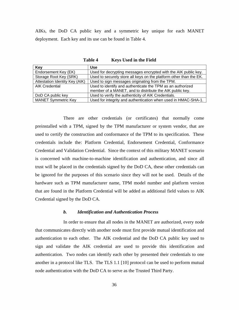
36
AIKs, the DoD CA public key and a symmetric key unique for each MANET
deployment. Each key and its use can be found in Table 4.
Table 4 Keys Used in the Field Key Use Endorsement Key (EK) Used for decrypting messages encrypted with the AIK public key. Storage Root Key (SRK) Used to securely store all keys on the platform other than the EK. Attestation Identity Key (AIK) Used to sign messages originating from the TPM. AIK Credential Used to identify and authenticate the TPM as an authorized
member of a MANET, and to distribute the AIK public key. DoD CA public key Used to verify the authenticity of AIK Credentials. MANET Symmetric Key Used for integrity and authentication when used in HMAC-SHA-1.
There are other credentials (or certificates) that normally come
preinstalled with a TPM, signed by the TPM manufacturer or system vendor, that are
used to certify the construction and conformance of the TPM to its specification. These
credentials include the: Platform Credential, Endorsement Credential, Conformance
Credential and Validation Credential. Since the context of this military MANET scenario
is concerned with machine-to-machine identification and authentication, and since all
trust will be placed in the credentials signed by the DoD CA, these other credentials can
be ignored for the purposes of this scenario since they will not be used. Details of the
hardware such as TPM manufacturer name, TPM model number and platform version
that are found in the Platform Credential will be added as additional field values to AIK
Credential signed by the DoD CA.
b. Identification and Authentication Process
In order to ensure that all nodes in the MANET are authorized, every node
that communicates directly with another node must first provide mutual identification and
authentication to each other. The AIK credential and the DoD CA public key used to
sign and validate the AIK credential are used to provide this identification and
authentication. Two nodes can identify each other by presented their credentials to one
another in a protocol like TLS. The TLS 1.1 [10] protocol can be used to perform mutual
node authentication with the DoD CA to serve as the Trusted Third Party.

37
c. AIK Credential Fields
The use of the AIK Credentials are application-specific, and as mentioned
above, these credentials will contain arbitrary identification fields by making use of the
extension fields available on X509v3 certificates [19]. The identification fields used in
the AIK Credential include: the machine host name, MANET deployment name, serial
number of hardware, version numbers of hardware and software, TPM manufacturer
name, TPM model number, platform version, and possibly other identifying information
that may be useful for determining access control rules.
3. Depot Operation
It is very difficult to ascertain any level of trust among machines in a traditional
MANET deployment once they have already been introduced into a hostile environment.
Therefore, it is essential to create and define a configuration that is known to be good for
the machines while their physical security can be assured. To establish this trust in the
system, a variety of methods should be employed at the depot including: security
clearances and background investigations for all depot operators, standardized
information security management practices such as ISO 17799/27001, configuration
management and auditing processes for both software development and system
configuration, code review and integrity verification, and ultimately secure handling and
protection of cryptographic key material at all times. The identification and
authentication protocol will rely solely on the aforementioned keys for security. The
TPM provides a high level of protection for all of the keys once they are installed,
however, the window of vulnerability from the time when the keys are generated until
they are installed must be thoroughly addressed. Robust and secure operating procedures
within the Depot will ensure that the keys are protected from confidentiality and integrity
threats from the time of their creation until their secure protection by the TPM.
a. Keys Used in the Depot
To provide integrity, confidentiality and authentication of the
communications for all machines participating in the MANET, a Public Key
Infrastructure (PKI) management scheme based on the TPM will be established during

38
the pre-deployment configuration process for each machine. Each machine will leverage
the functionality of its TPM for all security relevant cryptographic operations such as key
generation, storage, message signing, and signature verification. All of the necessary keys
that a machine needs will be generated and stored securely by the TPM of that machine
prior to deployment while it is still within the physically secure confines of the enterprise
depot. Each TPM will store five important keys: its own platform-unique Endorsement
Key (EK) pair, a Storage Root Key (SRK), an Attestation Identity Key (AIK), the AIK
Credential signed by the DoD CA private key, the DoD CA public key for signature
verification, and a symmetric key shared by each node in a single MANET deployment to
be used for integrity and authenticity in HMAC-SHA-1.
The EK, SRK, and AIK are standard keys used within the TPM and their
definitions can be found above in the TPM background. The two additional keys used in
our MANET scenario include the DoD CA public key for signature verification of AIK
Credentials and a symmetric key for protecting the integrity of MANET traffic. Since
this is a military scenario, it is assumed that the MANET nodes will also need to have
their identities signed and credentials issued by a DoD CA. A DoD CA serves as the root
of trust for our scenario, and also for the many other platforms, applications and user
certificates signed by the same CA which exist outside of our scenario. Since all of the
machines in this scenario and many other DoD entities place the root of their trust in this
same DoD CA key pair, it can be assumed that the private key will be heavily guarded
and secured by the DoD. Each machine in the MANET will store just the public key of
the DoD CA key pair in order to verify credentials issued by the DoD CA [11].
The MANET symmetric key shared amongst all machines in each
MANET deployment is used by the HMAC-SHA-1 message digest algorithm to provide
message integrity and authentication [39]. Due to the expensive computational cost of
performing encryption with public keys, a public key exchange is normally used to create
an agreed upon symmetric session key to protect message confidentiality [25]. For every
two nodes that wish to provide message confidentiality, a Diffie-Hellman key exchange
is used to generate a session key. Since session keys are temporal and generated in the
field, there is no requirement for them in the Depot. Table 5 identifies the keys and
certificates that will need to be installed on each TPM while at the Depot. The three

39
columns describe which entity is responsible for generating the key or credential, where it
will be generated at, and when it will be installed in the TPM if it has been generated
externally. All boxes which are highlighted in green identify a process which must take
place within the Depot.
Table 5 Keys Generated and Installed at the Depot Key Name Generated By Generated At Installed Endorsement Key (EK) TPM Manufacturer Offsite Already Installed Storage Root Key (SRK) TPM Owner Depot, Internal to
TPM Internally Generated
Attestation Identity Key (AIK) TPM Owner Depot, Internal to TPM
Internally Generated
AIK Credential DoD Offsite Installed at Depot DoD CA Public Key DoD Offsite Installed at Depot MANET Symmetric Key Depot
Administrator Depot, External to TPM
Installed at Depot
b. Processing Keys at the Depot
Every key to be used in a specific deployment must be generated in a
location that can be trusted, and then trustworthily installed on to the TPM. With a
COTS TPM platform, the only key that does not need to be managed in this scenario is
the EK which is assumed to be trusted as well as the TPM manufacturer. The second
column of Table 5 above lists four different entities responsible for generating the keys to
be installed on the TPM. The TPM Manufacturer and DoD PKI authority generate the
keys outside of the Depot environment. The TPM Owner is a TCG term which identifies
an entity with access to the TPM Owner AuthData. In this scenario, that person will be a
Depot Administrator who will assume the role of TPM Owner in order to generate the
keys internally on the TPM. The Depot Administrator will also generate the MANET
symmetric key, but this will take place outside of the TPM and thus does not require the
TPM Owner AuthData.
The SRK and AIK are created by the TPM Owner, and in order for this to
happen, the TPM platform first needs to have an Owner created by establishing a new
160-bit value for the owner authentication data. Even if a TPM Owner is already
established on the platform, it is recommended that the current Owner be cleared out and

40
a new Owner be established in order to start with a clean configuration for each new
MANET deployment. A new system being prepared for deployment with a TPM Owner
already established is in an indeterminate configuration state and no trust can be placed in
this configuration unless it has been known from the start and through all configuration
changes. When the new TPM Owner is created, the Owner’s AuthData must always be
protected from unauthorized disclosure. There should be only a few highly trusted
personnel (the Depot Administrators) with the appropriate security clearances who will
have access the TPM Owner AuthData, since this password allows full access to the TPM
whereby the configuration can be changed or decryption keys exposed. The TPM Owner
and other entity AuthData will need to be backed up and securely stored for
reconfiguration of the TPM, but by limiting its exposure to a small number of people, the
risk of its compromise can be managed more easily.
After new ownership is asserted on the TPM, the SRK and AIK can be
created by the TPM Owner. These two keys are associated with the current TPM Owner
and when the TPM Owner is invalidated, so too will the SRK and AIKs be invalidated.
The generation of these two keys can be trusted since the key generation takes place on
the TPM and the TPM protects these keys in a shielded location at all times. This key
generation process should only take place within the Depot by the Depot Administrators.
Of all the keys and credentials that need to be processed at the Depot prior
to deployment, the AIK Credential will take the longest amount of time because of the
need to interact with the DoD CA. The DoD CA takes the role of a Trusted Third Party
(TTP) that will bind the TPM public keys to the node’s identity information. After the
AIK key pair is created inside the TPM, the public key needs to be exported from the
TPM. This public key must then be combined with all of the identification information
that the Depot wishes to bind to this platform, such as the MANET deployment name,
serial number, hostname or other details. This combination is used to generate a
Certificate Signing Request (CSR). The CSR is then sent to the DoD CA to sign and
generate the AIK credential or certificate. Once the AIK Credential is created, it needs to
be transported back securely to the Depot. All information in the certificate and the
public key should be verified to match that which was sent in the CSR and then the
signature of the DoD CA should be validated with the DoD CA public key. After

41
confirmation of the certificate information and signature verification, the certificate can
be trusted even though it was generated outside of the Depot. Once that is complete, the
Depot Administrator will use the TPM to securely store the AIK Credential.
MANET TPM Laptop
AIKpub
Depot DoD CA
Gen AIK
Verify AIKpubAppend ID DataGen CSR
AIKcsr Sign CSRIssue CRT
AIKcrtVerify CRTStore in DB
AIKcrtStore CRT in TPM
Figure 8 AIK Credential Process
The DoD CA public key already exists and it can be trusted by
establishing its cryptographic binding to the actual DoD CA private key. Any certificate
signed by the DoD CA should be validated correctly by using the DoD CA public key.
After assurance is made that the DoD CA public key can be trusted and is correct, the
Depot Administrator assumes the role of TPM Owner and will use the TPM to securely
store the DoD CA public key.
The MANET symmetric key to be used in this scenario will be generated
at the Depot as a 160-bit key outside of the TPM and then securely installed onto the
system. Though the TPM provides no external interface for symmetric key generation, it
does provide an interface to its RNG and SHA-1 hashing algorithm. The symmetric key

42
will be generated by an external process using these two TPM-protected functions to 1)
collect a large amount of random data from the RNG and then 2) perform a SHA-1 hash
on it. Since the key generation processes (RNG and SHA-1) utilize the TPM’s protected
functions, and the key will be installed to the TPM by the Depot Administrator within the
physically secure confines of the Depot, the symmetric key itself can be trusted against
disclosure.
B. THREAT ANALYSIS
This threat analysis of the system scenario proposed in the CONOP described
above consists of a consideration for the usage and environmental assumptions in place,
as well as any residual threats which require remediation. The scenario incorporates the
use of a TPM and TBB on the platform of each node in the MANET. The TPM and TBB
each have their own Common Criteria protection profiles [8, 52] which state their design
assumptions and threats addressed in each. For the reader’s convenience, the assumptions
and threats specified in the profiles are provided in Appendices A-D.
1. Assumptions
In order to assess the threats involved in this CONOP scenario, the assumptions
must first be clearly defined. There are key operational environment assumptions to
consider in this scenario including the processes and operations that take place within and
between the TPM manufacturer, TPM, platform, MANET, Depot, and the DoD CA. The
assumptions presented below are named with a prefix such as “A” for a general
assumption of the system, “AD” for a configuration assumption of the Depot, “AF” for
an operational assumption of the Field, “AED” for assumption of the environment in the
Depot and “AEF” for assumption of the environment in the Field.
a. TPM Trusted Manufacture Assumption
One common assumption made by all users of a TPM is that the TPM is
manufactured to conform exactly to the TCG specification. While a conventional home
user cannot feasibly verify this, there have been some differences discovered among the
ways TPMs from different vendors operate [43]. These TPMs may still be in accordance
with the TCG specification even with these differences due to the liberty allowed to

43
vendors, though some TPMs may break from the specification as well [43]. Successful
subversion of the TPM at the hardware level would be impossible to adequately test for
or detect in most cases. The security assumption of “trust your hardware source” is
particularly important in a military use context and can be addressed by requiring the
manufacturer to go through a rigorous certification process, or through the use of a
trusted foundry to ensure that the hardware complies with the TPM 1.2 specification and
provides no additional functionality which adversely affects the security of the TPM and
its functions. Since the TPM is designed for general purpose computing with the main
intended audience being a home user, the assumption to trust the manufactured hardware
is often taken for granted. The threat and risk of hardware subversion is much greater to
a military user than a home user, so this assumption must be explicitly stated: the
hardware functions correctly and in conformance with the TCG specification. These
assumptions have been simplified to trust in the manufacturer and TPM itself in Table 6.
Table 6 TPM Manufacturer Assumptions # Assumption Name Description 1 A.Trusted_Manufacturer The manufacturer of the TPM is assumed to be trusted such that
the security of the TPM is not compromised. 2 A.Trusted_TPM The TPM is trusted to be a correct implementation of the TCG
specification without any compromise to security.
b. TPM Assumptions
As stated in the TCPA Trusted Platform Module (TPM) Protection Profile
(Version 1.9.7) [52], the secure usage and environmental assumptions of a TPM include:
1) proper configuration and 2) a physically secure environment. In Appendix A, the table
of TPM Assumptions has been recreated from the TPM Protection Profile to include both
the usage and environmental assumptions [52].
The assumption that the TPM will be installed and configured properly is
the core issue related to the establishment of remote identification and authentication in
the MANET. Before the system can be assumed to be in a secure state at any time in the
future, it is essential that the system be verified to have started with a secure initialization
and configuration. This is established by performing all TPM installation and
configuration within the secure confines of the Depot. Trust in the secure initialization of

44
the system after a platform reset is accomplished by the TBB, whose assumptions follow.
It is important to note however that the TPM is required to be present for the TBB to
function as specified by its protection profile [8].
The TCPA TPM protection profile assumes a physically protected
operating environment for the TPM. In the context of our military MANET scenario, the
TPM-enabled laptops are used within the confines of a military vehicle. It is assumed
that the military operator and the confines of the vehicle provide adequate physical
security to the TPM platform, and that additional physical security protections are in
place on the laptop itself. The laptop should be secured against operator access to the
physical presence assertion method of the TPM by unauthorized users, for example
through the use of a biometric authenticator and PIN, or through tamper resistance of the
laptop enclosure. In this way, the TPM physical protection assumption can be made.
Since the TPM has been engineered for COTS use, and because
engineering it for tamper resistance would have been prohibitively expensive for the mass
market, it was only engineered for tamper evidence. The military may be willing to pay
more though for a military-specific class of the TPM engineered for tamper resistance.
Additional hardware protections may also be put in place to create a tamper resistant
shield to the TPM system.
c. TBB Assumptions
Though the TCPA TPM Protection Profile makes the assumption of a
secure configuration, the depth of this secure configuration analysis must also extend to
the initialization of the platform as well. (For a more detailed discussion how the TBB is
involved in the platform chain of trust creation, please see the background Section “PC
Platform and the TPM” in Chapter II.) The only assumption in the TBB Protection
Profile, available in Appendix B, is that a certified TPM is connected to the IT
Environment in which the TBB operates. The IT Environment includes the technology
and functionality found on a PC Trusted Platform. These assumptions also include: a
platform reset signal which causes the CPU to reset and transfer execution immediately
to the CRTM, the mechanism for assertion of physical presence, and access limitations
enforced by the TPM in the absence of physical presence [8].

45
The TBB Protection Profile provides an analysis of both a standalone TBB
and a TBB that includes a maintenance package, which would allow for the general
updating or replacement of the CRTM. The assumption for our scenario is that the
trusted platform nodes of the MANET will not include a maintenance package with their
TBB. The assumptions from the TBB protection profile are available in Appendix B.
d. TSS Assumptions
The Trusted Software Stack (TSS), as defined in previous sections,
includes the TPM device driver, TDDL, TCS and TSP. While the highest level of
assurance would be provided if the TSS originated from a trusted development team (and
the TPM from a trusted foundry), this scenario will assume only a COTS Trusted
Platform Module. The TPM device driver and TDDL will be assumed to be provided by
the TPM manufacturer and operating system, though this is not necessarily so. All layers
of the TSS may be available from third parties and in particular as Free and Open Source
Software (FOSS). Along with the threat that the TPM hardware may be subverted,
particularly if destined for military use, subversion of the TSS should also be considered.
It would be much easier for a manufacturer or a third party to subvert a software package
such as the TSS, rather than the TPM hardware itself. It is assumed that the TSS is
certified to be compliant with the TSS specifications by the TCG [59]. The TSS
assumptions are included in Table 7.
Table 7 TSS Assumptions # Assumption Name Description 1 A.Certified_TSS The TSS operation is correct and can be trusted. Its trustworthiness is
certified by the companies it originated from, including the TPM manufacturer or other development teams.
e. Depot Assumptions
The enterprise depot environment is assumed to provide adequate physical
security for the TPM-enabled laptops against subversion from the time that they are
acquired, through the process of configuration and storage until they are finally deployed

46
for use. It is assumed that only trusted personnel will be authorized access to the laptops
for configuration purposes within the physically secure Depot environment. The Depot
will require all of its personnel to be vetted to a level of trust equal to or greater than all
end users and operators of the system. The Depot environment assumptions are provided
in Table 8.
Table 8 Depot Assumptions # Assumption Name Description 1 AD.Trusted_Personnel All personnel operating in the Depot environment are assumed to be
vetted to a level of trust commensurate with the level of protection necessary for the MANET in its field environment. If the MANET operating environment will be classified, all Depot personnel will hold the appropriate level of clearance.
2 AED.Physical_Security The Depot environment is assumed to be physically secure.
f. Field Assumptions
The Field environment is defined to be the operational environment that
the MANET and TPM-enabled laptops will be used in. For simplicity of the security
analysis, any location outside of the Depot is considered to be the Field environment –
where physical security cannot be assured. The greatest threats to the MANET include
Denial of Service (DoS) and interception of confidential information. Since it may be
impossible to prevent a physical level DoS attack on the electromagnetic spectrum (i.e.,
jamming) itself, we simply assume this threat will not be present. Another, more
threatening yet subtle kind of DoS attack, is on the MANET routing protocol, in which
case a node may simply refuse to forward packets. It is assumed that nodes authenticated
and authorized by the DoD CA will not perform these malicious routing DoS attacks.
It is assumed that the nodes in the MANET will only communicate with
other authorized nodes via mutual authentication of sender and receiver by verifying node
credentials. It is assumed that the confidentiality of all sensitive MANET traffic will be
protected by encryption of strength commensurate with the value of the data to be
protected. The MANET of military vehicles is assumed to operate within the context of a
convoy such that when they are mobile, they will be traveling together and remain well
within wireless communication range of each other. At least one node in the mostly
autonomous MANET would be able to receive regular external updates for distribution

47
amongst all other nodes. These updates would include changes to the Certificate
Revocation List (CRL) from the DoD CA and other data that may require timely updates.
The Field environment assumptions are available in Table 9.
Table 9 Field Assumptions # Assumption Name Description 1 AF.Authorized_Nodes Authorized nodes do not maliciously harm the MANET. 2 AF.Mutual_Authorization All nodes perform mutual identification and authentication
procedures to determine that each is authorized to communicate in the MANET in accordance with the DoD CA.
3 AF.Conf_Encryption The confidentiality of the MANET communication is protected by encryption at a level of strength commensurate with the level of protection necessary for the information.
5 AF.Trained_Operator An operator is trusted and will be trained to understand how to operate the system effectively and maintain system security.
4 AEF.Stable_Config The configuration of the platform cannot be changed in the Field environment since configuration changes cannot be assured in an environment whose physical security cannot be assured.
g. DoD CA and PKI Assumptions
The DoD CA will process the creation of all certificates and credentials
necessary for the full operation of the MANET. The DoD CA will interface with the
Depot in a timely manner for the processing of custom Certificate Signing Requests
(CSRs), including any extensions such as the subject alternate field used for MANET
node and deployment identification, and returning the requisite certificates in response.
In the proposed scenario, updates to the Certificate Revocation List (CRL) are assumed to
be created and distributed at least daily from the DoD CA to the MANET via secure
communication. Assumptions for the DoD CA and PKI process are listed in Table 10.
Table 10 DoD CA and PKI Assumptions # Assumption Name Description 1 A.CRL_Distribution The CRL is distributed to the MANET on a daily basis. 2 A.CSR_SubAltFields The CA will sign a CSR with customized subject alternate fields

48
2. Threats
There are a great number of threats to be considered in our TPM-enabled military
MANET scenario. Threats must be address for the overall system context, both in the
Field and within the Depot. Since the TPM is used to provide the foundation for all of
the security functions in this scenario, such as identification and authentication as well as
integrity reporting, threats to the TPM must be specifically addressed. Fortunately, since
the TPM has gone through the Common Criteria Evaluation and was verified at EAL
Level 3, there is a well defined list of the threats in the TPM Protection Profile [52] that
are considered and addressed in the construction of the TPM. The Threats identified for
both the TPM and TBB in their Protection Profiles can be found in Appendices C and D
for reference. Our scenario needs to consider these threats and any possible new ones in
both the Depot and Field environments in order to ensure that they are mitigated by the
system security objectives. The identified threats have been named with the prefixes
“TD” for a threat that applies to the Depot and “TF” for a threat that applies to the Field
environment.
a. Depot Threats
There are additional threats to be considered in our scenario within the
Depot environment. This is where the TPM laptops are configured, their cryptographic
keys are generated and processed, and they are operationally tested before being
deployed. Table 11 outlines threats to be addressed by the Depot environment. The
threats in Table 11 were derived from the Consistency Instruction Manual for Medium
Robustness Environments and in consideration of the CONOP [2].

49
Table 11 Threats to Depot Security # Threat Name Description 1 TD.Admin_Error An administrator may incorrectly install or configure the platform, or
install a corrupted configuration resulting in ineffective security mechanisms.
2 TD.Admin_Rogue An administrator’s intentions may become malicious resulting in sensitive data being compromised.
3 TD.Audit_Compromise A malicious administrator or process may view audit records, cause them to be lost or modified, or prevent future audit records from being recorded.
4 TD.Crypto_Compromise A malicious administrator or process may cause key, data or other sensitive information to be inappropriately accessed (view, modify, or delete) and thus compromising the cryptographic mechanisms and data processed by the TPM.
5 TD.Poor_Test Lack of or insufficient tests to demonstrate the TPM functions operate correctly may result in incorrect behavior and potential security vulnerabilities. Self-tests may check out correctly, but specific implementations may vary from vendor to vendor.
b. Field Threats
Additional threats may be encountered that need to be taken into
consideration for the integrity of the system to remain robust while it is operational
within the Field environment. Table 12 outlines the threats to be addressed in the Field
environment. The threats in Table 12 were derived with guidance from the Consistency
Instruction Manual for Medium Robustness Environments and in consideration of the
CONOP [2].
Table 12 Threats to Field Security # Threat Name Description 1 TF.Eavesdrop A malicious operator or process may observe or modify sensitive
data transmitted between physically separate parts of the system. 2 TF.Resource_Exhaustion A malicious operator or process may block others from the
system resources through a resource exhaustion or denial of service attack. An adversary may cause a denial of service in the wireless spectrum that prevents the platform from communicating.
3 TF.Replay Another wireless node may attempt unauthorized access by replaying authentication information.
4 TF.Unattended_Session A malicious operator may gain unauthorized access to an unattended session.
5 TF.Unidentified_Actions A potential security violation of the system may occur and not be discovered until the system is returned to the Depot.

50
c. Rationale
The rationale for these threats exists in consideration of the capabilities of
the TPM, administrative operators in the Depot, and the potential hazards of operating in
a military MANET scenario. The TPM threats are addressed by the TPM design and
apply mostly to the administrators operating in the Depot. Depot operating requirements
must be rigorously enforced to ensure assurance and accountability to all processes that
take place. Only qualified personnel with the appropriate security clearances would be
allowed to perform the administrative operations on the platforms, and an audit trail
should record all people who accessed each TPM and the final TPM configurations. To
the furthest extent possible, automated routines, which have been certified by
administrators of the Depot and placed under configuration management, would perform
most of the work necessary on creating new keys internally in the TPM, distributing and
installing new migratable keys onto the TPM, and performing the backup and
maintenance procedures that specifically deal with sensitive data since automating
processes will prevent the occasional user error. In the Field environment, the operators
will need to be trained to protect the platform equipment from unattended sessions to the
furthest extent possible. Remaining threats are addressed or mitigated in part by the TPM
and the operating procedures within the Depot and Field.
C. OBJECTIVE DEFINITIONS
The security objective definitions of a system are intended to address specific
threats to security. The security objectives of the TPM and the TBB have been defined in
their Protection Profiles and for the sake of brevity and reader reference, these tables
have been recorded in Appendices E and F [8, 52]. Further security objectives for the
Depot and Field environments of the military MANET are below. The prefix “OD” for
each objective name stands for “Objective of the Depot”, “OED” stands for “Objective of
the Environment of the Depot”, “OF” stands for “Objective of the Field”, and “OEF”
stands for “Objective of the Environment of the Field”.

51
1. Depot Objectives
The objectives of the Depot environment are to provide a secure configuration
environment for the TPM platform and address the assumptions and threats identified in
Section B “Threat Analysis” of this chapter. The security objectives of the Depot are
found in Table 13.
Table 13 Security Objectives of the Depot # Objective Name Description 1 OD.Robust_Admin_Guidance The administrators of the TPM platform in the Depot will be
provided with the necessary information and training for secure configuration and installation of each laptop system.
2 OD.Admin_Role The administrative role for configuration of the TPM-enabled system will be designated to select individuals so as to isolate administrative actions and access to sensitive information.
3 OD.Change_Management The configuration of, and all changes to, the TPM-enabled system and its supporting software will be analyzed, tracked, and controlled throughout the system’s lifecycle.
4 OD.Admin_Vetting The administrators of the TPM platforms will undergo a vetting process by which greater trust can be placed in them to perform their role without compromising security.
5 OD.Audit_Protection All audit records will be protected against compromise. 6 OD.Crypto_Handling All cryptographic material will be handled with the security
procedures commensurate with the highest sensitivity and classification level of the data that the keys are authorized to protect in order to prevent against cryptographic compromise.
7 OD.Thorough_Func_Testing The TPM platforms will undergo appropriate self tests as well as operational and security functional testing while in the Depot to demonstrates the security functions satisfy the requirements.
8 OED.Physical_Security The Depot will provide a physically secure environment for the configuration of the systems.
2. Field Objectives
The objectives of the Field environment address the threats anticipated to be
encountered within the Field. The security objectives of the Field are found in Table 14.

52
Table 14 Security Objectives of the Field # Objective Name Description 1 OF.Protect_In_Transit The system will protect user and security function data against
compromise to integrity, confidentiality and authenticity when it is in transit from one node in the MANET to another. Only authorized nodes will communicate within the MANET and all nodes will perform mutual authentication before establishing further communication.
2 OF.Resource_Exhaustion The system will provide mechanisms that mitigate attempts at resource exhaustion encountered in the MANET protocols and wireless domain.
3 OF.Replay_Detection The system will provide a means to detect and reject the replay of authentication by unauthorized nodes in the MANET.
4 OF.Operator_Vetting The operators of the TPM platforms will undergo a vetting process by which greater trust can be placed in them to perform their role without compromising security.
5 OF.Operator_Training All operators will be provided appropriate training on the operational and security precautions for use.
6 OF.Robust_Access The TPM Platform will provide mechanisms that control an operator’s logical access to the system and explicitly deny access to unauthorized operators.
7 OF.Audit_Review The system will provide the capability to selectively view audit information and alert the operator or administrator of identified potential security violations.
8 OEF.Stable_Config All system configuration and security assumptions from the Depot environment will remain unchanged in the Field because there are no administrative system changes to be made in the Field.
3. Rationale
The Security Objectives have been defined specifically to address the threats
identified above. Rationale for the TPM and TBB objectives can be found in their
Protection Profiles [8, 52]. The Rationale for the Objectives of the Depot and Field
environments can be traced back to the assumptions and threats of these two
environments and processes that take place therein. The key functional differences
between the Depot and Field environments are that one is a trusted environment and the
other is not, such that all system configuration changes are made within the Depot and
there is no administrative access to the systems for configuration changes once in the
Field. Other objectives relate to the assumptions of the TPM hardware and software as
well as the Certificate Authority are considered outside the scope of analysis for this
thesis. The mapping of assumptions and threats to objectives in the Depot and Field
environments is presented in Tables 15 and 16.

53
Table 15 Objectives Mapping for Depot
Assumption/Threat Name Objective Name
AD.Trusted_Personnel OD.Admin_Role
OD.Admin_Vetting
AED.Physical_Security OED.Physical_Security
TD.Admin_Error OD.Robust_Admin_Guidance
OD.Audit_Protection
OD.Change_Management
TD.Admin_Rogue OD.Admin_Vetting
TD.Audit_Compromise OD.Audit_Protection
TD.Crypto_Compromise OD.Crypto_Handling
TD.Poor_Test OD.Thorough_Func_Testing
Table 16 Objectives Mapping for Field
Assumption/Threat Name Objective Name
AF.Authorized_Nodes OF.Protect_In_Transit
AF.Mutual_Authorization OF.Protect_In_Transit
AF.Conf_Encryption OF.Protect_In_Transit
AF.Trained_Operator OF.Operator_Vetting
OF.Operator_Training
AEF.Stable_Config OEF.Stable_Config
TF.Eavesdrop OF.Protect_In_Transit
TF.Resource_Exhaustion OF.Resource_Exhaustion
TF.Replay OF.Protect_In_Transit
OF.Replay_Detection
TF.Unattended_Session OF.Operator_Training
OF.Robust_Access
TF.Unidentified_Actions OF.Audit_Review

54
D. REQUIREMENTS
The requirements of the system implementation are derived from the objectives
defined to address the identified threats in prior sections. The Requirements for the TPM
and TBB, as presented in the Protection Profiles, can be found in Appendices G and H
respectively. The requirements for the Depot and Field environments have been created
specifically below to implement the objectives defined above. The prefix “RD” stands
for “Requirement of the Depot”, “RED” stands for “Requirement of the Environment in
the Depot”, “RF” stands for “Requirement of the Field” and “REF” stands for
“Requirement of the Environment in the Field”.
1. Depot Requirements
The Security Functional Requirements of the Depot have been defined to address
the objectives identified above and are found in Table 17. Where possible, mappings
from objectives to requirements have been followed as defined in Appendix B of the
Consistency Instruction Manual for Medium Robustness Environments [2].
Table 17 Requirements of the Depot # Functional Requirement Description 1 RD.Guidance_Docs Administrator shall ensure delivery of TPM/TBB is not corrupted.
There shall be complete and unambiguous documentation for the Installation, Key Generation, Startup and Administrator guidance on TPM operation such that the TPM Platform cannot be misconfigured due to unclear guidance.
2 RD.Admin_Access The Depot shall have procedures and technical measures in place to ensure that only Administrators shall have access to and perform configuration of TPM platforms.
3 RD.Change_Management The Depot shall have a CM plan and partial automated CM system to provide change control and track changes and problems. Change management shall include the documentation and guidance for administrators and operators. There shall be documented measures employed to ensure that integrity and confidentiality is maintained. Operational procedures shall meet ISO Standards, including ISO security standard ISO17799.
4 RD.Admin_Clearance Administrators at the Depot shall be properly vetted and granted a security clearance commensurate with the level required for configuring the TPM Platforms.
5 RD.Audit_Protection Administrators controls audit events and is the only one who can modify or delete audit records and provide for the integrity of the audit trail from within the Depot.

55
6 RD.Crypto_Handling All cryptographic material shall be handled by vetted and cleared administrators in accordance with procedures and auditing defined for its classification to prevent any unauthorized disclosure. All transportation and storage of cryptographic material shall be recorded in an audit log with a time, date and person responsible.
7 RD.Vuln_Assessment There shall be a vulnerability assessment of the system configuration to ensure that no vulnerabilities are introduced.
8 RD.Self_Test_Success A functional self-test of the TPM as well as operational tests for the hardware and software of the system shall be performed.
9 RED.Physical_Security The Depot shall be physically secure from overt hostile actions.
2. Field Requirements
The Security Functional Requirements of the Field have been defined to address
the Field objectives identified above and are found in Table 18. Where possible,
mappings from objectives to requirements have followed Appendix B of the Consistency
Instruction Manual for Medium Robustness Environments [2].
Table 18 Requirements of the Field # Functional
Requirement Description
1 RF.MANET_Encrypt All established MANET communication shall be encrypted if it is sensitive in nature.
2 RF.Resource_Protection The MANET communication protocol shall not prohibitively consume system resources that deny other operations to perform.
3 RF.Replay_Detect The MANET authentication protocol shall detect and deny replay authentication attempts by use of timestamps and nonces.
4 RF.Operator_Clearance All operators shall have been properly vetted and granted a security clearance commensurate with the level required for using the TPM Platforms.
5 RF.Operator_Guidance The operator shall be provided with complete and unambiguous documentation and guidance for all applicable security procedures such as authentication and normal use such that the system cannot be used insecurely due to operator confusion.
6 RF.Robust_Access Every user shall be identified and authorized before given access to use the system and only a limited set of services that do not require authentication shall be available otherwise.
7 RF.Tamper_Resistance Tamper resistance security shall be placed around the TPM Platform while it is in use in the field such that evidence of tampering shall erase ownership and related information in the TPM.
8 RF.Audit_Alert Any event that indicates a security violation shall generate an alarm. The events shall be configured by the Security Administrator but evident to the Operator as well. The operator shall be informed of audit events and report suspicious activities to the security Administrator for review at the Depot.
9 REF.Stable_Config The configuration of the system shall remain unchanged and there shall not be any method for change while in the Field environment.

56
3. Rationale
The objectives and requirements for the TPM and TBB are specified in their
respective Protection Profiles, which also include a rationale for their completeness [8,
52]. The requirements for the Depot and Field environments have been created in
consideration of the objectives defined and the details specific to the military MANET
scenario as discussed in previous sections. Since there is at least one requirement defined
for every objective, all of the objectives have been met. A mapping of the Depot and
Field objectives to requirements is provided in Tables 19 and 20.
Table 19 Objectives to Requirements Mapping for Depot
Objective Name Requirement Name
OD.Robust_Admin_Guidance RD.Guidance_Docs
OD.Admin_Role RD.Admin_Access
OD.Change_Management RD.Change_Management
OD.Admin_Vetting RD.Admin_Clearance
OD.Audit_Protection RD.Audit_Protection
OD.Crypto_Handling RD.Crypto_Handling
OD.Thorough_Func_Testing RD.Vuln_Assessment
RD.Self_Test_Success
OED.Physical_Security RED.Physical_Security

57
Table 20 Objectives to Requirements Mapping for Field
Objective Name Requirement Name
OF.Protect_In_Transit RF.MANET_Encrypt
OF.Resource_Exhaustion RF.Resource_Protection
OF.Replay_Detection RF.Replay_Detect
OF.Operator_Vetting RF.Operator_Clearance
OF.Operator_Training RF.Operator_Guidance
OF.Robust_Access RF.Robust_Access
RF.Tamper_Resistance
OF.Audit_Review RF.Audit_Alert
OEF.Stable_Config REF.Stable_Config

58
THIS PAGE INTENTIONALLY LEFT BLANK

59
IV. TPM COMMANDS
The TPM design specification identifies all of the commands which the TPM
driver must support. From TPM v1.1b to TPM v1.2, several commands were deprecated
and deleted from the new specification while still many more were added and thus
increased the TPM functionality. In order to better understand the TPM functionalities
that may be leveraged in this CONOP, those TPM commands which are considered the
most significant and necessary are defined in Table 21. The table provides the name of
the TPM command itself, command category, a short description, and whether or not
access to the command is Allowed or Blocked by default in Microsoft Windows Vista™
according to the TPM Command Management application. Within the TPM
Management Console, the TPM Command Management application provides the system
administrator with the ability to examine each of these commands and selectively allow
or block their use. This is the only known application where the administrator can apply
direct access control on TPM commands as well as within the group policy editor on
Windows Vista™.
From the command listing in Table 21, several categories of commands have been
removed from the complete listing of those available since their use in this CONOP have
not been fully defined. Those categories of commands not included for this CONOP
include: Migration, Maintenance Functions (except for the
TPM_KillMaintenanceFeature command), Authorization Sessions, Delegation, Session
Management and Monotonic Counter. The Maintenance Functions were designed so that
updates to the TPM may be made remotely by the TPM manufacturer. For this CONOP,
the TPM_KillMaintenanceFeature command was included specifically because it should
be executed to disable any future Maintenance attempts. All of the other commands
would likely be used in typical TPM operations such as: the generation of keys,
authentication operations, integrity measurement and attestation, secure storage of data,
and secured transport of data.
The Status (Allowed or Blocked) of these commands in Table 21 corresponds
only to the default Status assigned to them in Microsoft Windows Vista, and to whether
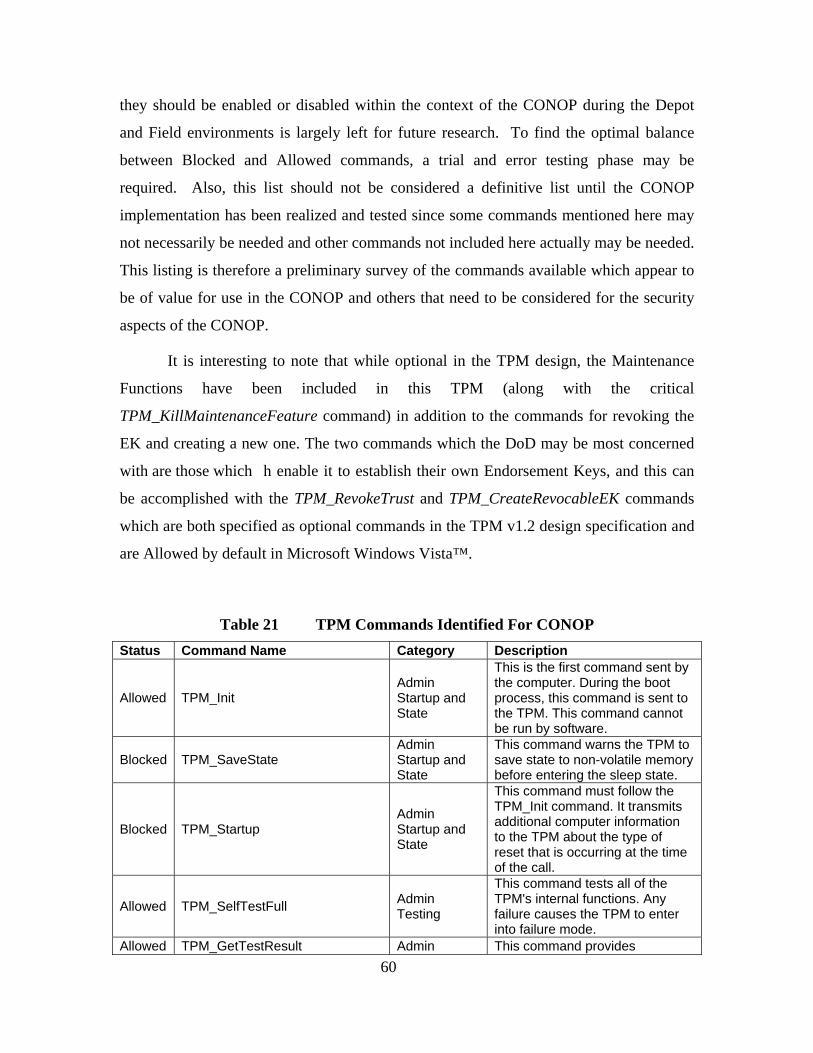
60
they should be enabled or disabled within the context of the CONOP during the Depot
and Field environments is largely left for future research. To find the optimal balance
between Blocked and Allowed commands, a trial and error testing phase may be
required. Also, this list should not be considered a definitive list until the CONOP
implementation has been realized and tested since some commands mentioned here may
not necessarily be needed and other commands not included here actually may be needed.
This listing is therefore a preliminary survey of the commands available which appear to
be of value for use in the CONOP and others that need to be considered for the security
aspects of the CONOP.
It is interesting to note that while optional in the TPM design, the Maintenance
Functions have been included in this TPM (along with the critical
TPM_KillMaintenanceFeature command) in addition to the commands for revoking the
EK and creating a new one. The two commands which the DoD may be most concerned
with are those which h enable it to establish their own Endorsement Keys, and this can
be accomplished with the TPM_RevokeTrust and TPM_CreateRevocableEK commands
which are both specified as optional commands in the TPM v1.2 design specification and
are Allowed by default in Microsoft Windows Vista™.
Table 21 TPM Commands Identified For CONOP Status Command Name Category Description
Allowed TPM_Init Admin Startup and State
This is the first command sent by the computer. During the boot process, this command is sent to the TPM. This command cannot be run by software.
Blocked TPM_SaveState Admin Startup and State
This command warns the TPM to save state to non-volatile memory before entering the sleep state.
Blocked TPM_Startup Admin Startup and State
This command must follow the TPM_Init command. It transmits additional computer information to the TPM about the type of reset that is occurring at the time of the call.
Allowed TPM_SelfTestFull Admin Testing
This command tests all of the TPM's internal functions. Any failure causes the TPM to enter into failure mode.
Allowed TPM_GetTestResult Admin This command provides

61
Testing manufacturer-specific and diagnostic information regarding the results of the self test.
Allowed TPM_OwnerSetDisable Admin Opt-in
This command allows the TPM owner to enable or disable the TPM. See the descriptions for the TPM_PhysicalEnable and TPM_PhysicalDisable commands for more information.
Allowed TPM_PhysicalEnable Admin Opt-in
This command enables the TPM. This command requires physical presence at the computer and is executed by the BIOS. Turning on the TPM involves enabling and activating the TPM (with TPM_PhysicalSetDeactivated).
Allowed TPM_PhysicalDisable Admin Opt-in
This command disables the TPM. This command requires physical presence at the computer and cannot be run by the operating system. Turning off the TPM involves disabling or deactivating the TPM (with TPM_PhysicalSetDeactivated).
Allowed TPM_PhysicalSetDeactivated Admin Opt-in
This command activates or deactivates the TPM. This command requires physical presence at the computer and cannot be run by the operating system. Microsoft does not recommend that this command be blocked so that the TPM may always be deactivated by the operator of a particular environment.
Allowed TPM_SetTempDeactivated Admin Opt-in
This command allows the operator of the computer to deactivate the TPM until the next computer restart. The operator must either have physical presence at the computer or present the operator authorization value defined with the TPM_SetOperatorAuth command.
Allowed TSC_PhysicalPresence Admin Ownership
This command asserts physical presence at the computer. This command cannot be run by the operating system.
Allowed TPM_TakeOwnership Admin Ownership
This command takes ownership of the TPM with a new owner authorization value, derived from the owner password. Among other conditions that must be met before this command can run, the
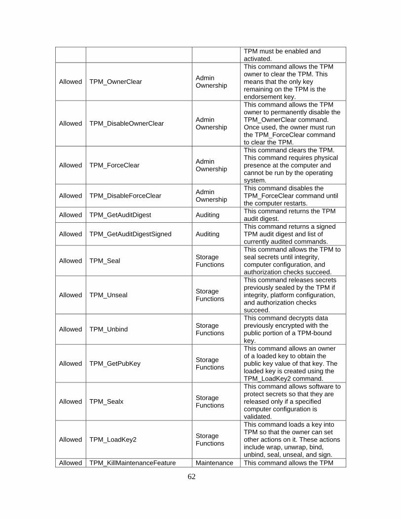
62
TPM must be enabled and activated.
Allowed TPM_OwnerClear Admin Ownership
This command allows the TPM owner to clear the TPM. This means that the only key remaining on the TPM is the endorsement key.
Allowed TPM_DisableOwnerClear Admin Ownership
This command allows the TPM owner to permanently disable the TPM_OwnerClear command. Once used, the owner must run the TPM_ForceClear command to clear the TPM.
Allowed TPM_ForceClear Admin Ownership
This command clears the TPM. This command requires physical presence at the computer and cannot be run by the operating system.
Allowed TPM_DisableForceClear Admin Ownership
This command disables the TPM_ForceClear command until the computer restarts.
Allowed TPM_GetAuditDigest Auditing This command returns the TPM audit digest.
Allowed TPM_GetAuditDigestSigned Auditing This command returns a signed TPM audit digest and list of currently audited commands.
Allowed TPM_Seal Storage Functions
This command allows the TPM to seal secrets until integrity, computer configuration, and authorization checks succeed.
Allowed TPM_Unseal Storage Functions
This command releases secrets previously sealed by the TPM if integrity, platform configuration, and authorization checks succeed.
Allowed TPM_Unbind Storage Functions
This command decrypts data previously encrypted with the public portion of a TPM-bound key.
Allowed TPM_GetPubKey Storage Functions
This command allows an owner of a loaded key to obtain the public key value of that key. The loaded key is created using the TPM_LoadKey2 command.
Allowed TPM_Sealx Storage Functions
This command allows software to protect secrets so that they are released only if a specified computer configuration is validated.
Allowed TPM_LoadKey2 Storage Functions
This command loads a key into TPM so that the owner can set other actions on it. These actions include wrap, unwrap, bind, unbind, seal, unseal, and sign.
Allowed TPM_KillMaintenanceFeature Maintenance This command allows the TPM

63
Functions (Optional)
owner to prevent the creation of a maintenance archive using the TPM_CreateMaintenanceArchive command. This action is valid until a new TPM owner is set using the TPM_TakeOwnership command.
Allowed TPM_CertifyKey Cryptographic Functions
This command certifies a loaded key (created by TPM_LoadKey2) with the public portion of another key. A TPM identity key may only certify non-migratable keys.
Allowed TPM_Sign Cryptographic Functions
This command signs data with a loaded signing key and returns the resulting digital signature.
Allowed TPM_GetRandom Cryptographic Functions
This command returns random data of a specified length from the TPM random number generator.
Allowed TPM_StirRandom Cryptographic Functions
This command adds entropy to the TPM random number generator state.
Blocked TPM_SHA1Start Cryptographic Functions
This command starts the process of calculating a SHA-1 digest. This command must be followed by execution of TPM_SHA1Update or the SHA-1 process is invalidated.
Blocked TPM_SHA1Update Cryptographic Functions
This command inputs complete blocks of data into a pending SHA-1 digest (started by TPM_SHA1Start).
Blocked TPM_SHA1Complete Cryptographic Functions
This command completes a pending SHA-1 digest process and returns the resulting SHA-1 hash output.
Blocked TPM_SHA1CompleteExtend Cryptographic Functions
This command completes a pending SHA-1 digest process, returns the resulting SHA-1 hash output, and incorporates this hash into a specified platform configuration register (PCR).
Allowed TPM_CreateEndorsementKeyPair Endorsement Key Handling
This command creates the TPM endorsement key (EK), if this key does not already exist.
Allowed TPM_CreateRevocableEK Endorsement Key Handling
This command creates the TPM endorsement key (EK). The user can also specify whether the EK can be reset, and can specify the authorization value necessary to reset this key (if this value is not to be generated by the TPM). This is an optional command that may not be supported by the computer manufacturer.

64
Allowed TPM_RevokeTrust Endorsement Key Handling
This command clears a revocable TPM endorsement key (generated by TPM_CreateRevocableEK) and resets the TPM, if it finds the correct authorization value for this reset. This command requires physical presence at the platform and cannot be run by the operating system.
Allowed TPM_MakeIdentity Identity Creation and Activation
This command allows the TPM owner to generate an Attestation Identity Key (AIK) that can be used to sign information generated internally by the TPM.
Allowed TPM_ActivateIdentity Identity Creation and Activation
This command allows the TPM owner to unwrap the session key that allows for the decryption of the Attestation Identity Key (AIK) credential, thereby obtaining assurance that the credential is valid for the TPM.
Blocked TPM_Extend
Integrity Collection and Reporting
This command adds a new digest to a specified platform configuration register (PCR) and returns this extended digest.
Allowed TPM_PCRRead
Integrity Collection and Reporting
This command returns the contents of a specified platform configuration register (PCR).
Blocked TPM_Quote
Integrity Collection and Reporting
This command returns a signed digest that is a combination of the contents of a specified platform configuration register (PCR) and some specified external data. The digest is signed with a loaded key. This command would be used for attestation purposes.
In Table 22, the tasks associated with system initialization have been defined
along with the corresponding TPM commands that would need to be used for each.

65
Table 22 TPM Commands for TPM Initialization Task TPM Commands Description
Clear the TPM
TPM_OwnerClear TPM_ForceClear
To clear the TPM is to remove the owner and all associated keys. TPM_OwnerClear requires owner authentication while TPM_ForceClear requires evidence of physical presence.
Disable the TPM TPM_PhysicalDisable
The TPM is disabled from use with the TPM_PhysicalDisable command and requires evidence of physical presence.
Reinitialize Hard Disk None TPM use not required
Partition and Format None TPM use not required
Enable the TPM TPM_PhysicalEnable
The TPM is enabled with TPM_PhysicalEnable and evidence of physical presence for authorization.
Install OS & Software None TPM use not required
Activate the TPM TPM_PhysicalSetDeactivated
The TPM is activated (once enabled) with the TPM_PhysicalSetDeactivated command and evidence of physical presence for authorization.
Revoke TPM Trust TPM_RevokeTrust
If the EK in the TPM was generated by TPM_CreateRevocableEK, it can be revoked with TPM_RevokeTrust and evidence of physical presence.
Create EK TPM_CreateRevocableEK A revocable EK is created with the command TPM_CreateRevocableEK which is an optional TPM command.
Take Ownership TPM_TakeOwnership
Ownership of a TPM that is both enabled and activated is made with the command TPM_TakeOwnership.
TPM Self-Test
TPM_SelfTestFull TPM_GetTestResult
TPM_SelfTestFull tests the internal functions of the TPM while TPM_GetTestResult provides manufacturer-specific and diagnostic information regarding the results of the last run self test.
In Table 23, the tasks associated with system configuration are presented along
with the TPM commands that would be used for each.
Table 23 TPM Commands for System Configuration Task TPM Commands Description
Create AIK TPM_MakeIdentity TPM_ActiveIdentity
TPM_MakeIdentity generates an Attestation Identity Key (AIK) that can be used to sign information generated internally by the TPM. TPM_ActiveIdentity allows the TPM owner to unwrap the session key that allows for the decryption of the Attestation

66
Identity Key (AIK) credential, thereby obtaining assurance that the credential is valid for the TPM.
Create AIK Credential
TPM_LoadKey2 TPM_GetPubKey TPM_Sign TPM_CertifyKey
TPM_LoadKey2 loads a key into TPM so that the owner can set other actions on it. These actions include wrap, unwrap, bind, unbind, seal, unseal, and sign. TPM_GetPubKey allows an owner of a loaded key to obtain the public key value of that key. The loaded key is created using the TPM_LoadKey2 command. TPM_Sign signs data with a loaded signing key and returns the resulting digital signature. TPM_CertifyKey verifies the signature of a certificate.
Create MANET Key TPM_GetRandom TPM_StirRandom
The SHA1 and Random number generator commands can be used to create the symmetric deployment key by collecting random data from the TPM_GetRandom and TPM_StirRandom functions.
Install Keys TPM_Seal TPM_Sealx
Keys and other data can be protected by the TPM by using the TPM_Seal commands.
Backup Keys None
The TPM is not required to backup the externally created keys and all internally created keys will remain within the TPM to maintain their integrity.
Configure TPM TPM_KillMaintenanceFeature
The TPM should be configured to disable the Maintenance functionality in the field environment,
Configure Disk Encryption TPM_Extend TPM_PCRRead TPM_SHA1CompleteExtend
The TPM commands used by the Disk encryption process remain to be determined though they will rely on integrity measurement and reporting functionalities such as: TPM_Extend, TPM_PCRRead, and TPM_SHA1CompleteExtend.
Configure Trusted Boot TPM_Extend TPM_PCRRead TPM_SHA1CompleteExtend
The TPM commands used to configure the trusted boot process of the TPM-enabled system are to be determined though they will rely on integrity measurement and

67
reporting functionalities such as: TPM_Extend, TPM_PCRRead, and TPM_SHA1CompleteExtend.

68
THIS PAGE INTENTIONALLY LEFT BLANK

69
V. DEPOT MANAGEMENT PROCESS
The Depot management process outlines the necessary procedures to be
accomplished before a TPM-enabled system is deployed into the field environment.
These procedures include system hardware and software acquisition, initialization,
configuration, and operational testing prior to deployment. The operating systems
considered for this process include Microsoft Windows Vista™ and GNU/Linux systems
using the TrouSerS TSS library and Trusted Grub as the secure boot loader.
A. ACQUISITION
In acquiring a laptop for the context of this MANET operation, a few
requirements and suggestions need to be kept in mind. First of all, the system hardware
must include a TPM (version 1.2) and a motherboard with a supporting TCG-compliant
BIOS in order to take advantage of the core functionality required of this CONOP.
Software requirements include a TPM-supporting operating system and TCG-compliant
Trusted Software Stack (TSS). The BitLocker hard drive encryption service in Microsoft
Windows Vista™ Ultimate and Enterprise editions also requires the system BIOS to
support USB devices at system startup [31]. In considering TPM model choices, the
TPM specification [57] mentions there is an “optional” command for revoking trust in the
EK. For an entity such as the DoD in this scenario, it is advisable for heightened security
purposes to have this optional command be available so that ultimately the DoD may
create their own EK to trust and store on the TPM. A listing of the required and
suggested features of the laptop platform is provided in Table 24.
Table 24 Acquisition Requirements and Suggestions
Component Description Necessity
TPM version 1.2 Latest version of TPM Required
Supporting BIOS Should come preinstalled on motherboard Required
USB boot functionality Standard in BIOS, for BitLocker secure boot support Required
USB storage drive Used for BitLocker secure boot support Suggested
Revoke Trust capability TPM feature desired for DoD use Suggested

70
B. SYSTEM INITIALIZATION
Once a system that meets the requirements has been acquired, it must be
initialized to a clean and secure state. This will include clearing and formatting the hard
drive, installing a new operating system from trusted media, and initializing the TPM
with a new Owner for the environment. The full system initialization process should take
place before each system deployment in order to ensure that a common security
foundation has been established on every node prior to its use in the field.
Each task to be done during the system initialization phase is outlined in Table 25
while those emphasized in italics are regarded as optional due to the potential technical
and environmental limitations of revoking the EK. While general guidance is provided
on how to perform each task under different operating environments (e.g., BIOS and
operating system) since an operating system is not required for many of these steps,
detailed instructions on how to perform each task of the system initialization process in a
Microsoft Windows Vista™ environment is provided in Appendix I, “The Depot
Management Guide.”
Table 25 System Initialization Tasks
Task Name Description
Clear TPM Remove TPM Owner and associated information and keys if they exist
Disable TPM Deactivate and Disable the TPM from within the BIOS
Reinitialize Hard Disk Remove all data from hard disk
Partition and Format Preparation of hard disk may take place during OS install
Enable TPM Enable the POST environment to detect the TPM but do not Activate it
Install OS & Software Install TPM-enabled OS, TSS and other software for MANET operation
Activate TPM Activate the TPM for use by the OS and for Ownership to be taken
Revoke TPM Trust Revoke EK if possible and desired (Optional)
Create EK If Trust in the TPM has been revoked, then a new EK must be created and
installed onto the TPM (Optional)
Take Ownership Perform TPM Initialization and create new TPM Owner
TPM Self-test Ensure TPM works functionally

71
The following sections describe the methods and tools that can be used to
accomplish each task in the System Initialization process. The methods illustrated below
for both Microsoft Windows Vista™ and GNU/Linux serve only to familiarize the reader
with the process and should not be used as instructions for performing these tasks as they
have not been tested. The explanations of how the tpm-tools programs function comes
from the descriptions in the corresponding man pages.
1. Clear the TPM
If a TPM Owner is currently installed in the TPM, it should be removed so that a
new TPM Owner may be installed. When a TPM is cleared, the TPM Owner AuthData is
deleted along with the SRK AuthData such that the keys and data associated with the past
Owner and SRK cannot be retrieved. The TPM may be cleared from within the BIOS,
with physical presence serving as the authorization, or from within the operating system
itself, where knowledge of the TPM Owner password is required to Clear the TPM. A
TPM that has been cleared is said to have been set to its “factory defaults” with no
Ownership set. On Microsoft Windows Vista™, the Microsoft Management Console
snap-in for TPM Management provides the option to clear the TPM [36]. On
GNU/Linux environments, the tpm-tools package of TrouSerS provides a command to
assert physical presence and to also clear the TPM [55]. Table 26 provides an outline of
the methods available to clear the TPM in different environments.

72
Table 26 Methods to Clear the TPM Environment Method
BIOS This procedure is BIOS specific. The BIOS Setup should provide the option
to clear the TPM with proof of physical presence.
Windows Vista™ The TPM Management Console must be started by running tpm.msc, and
then click on Clear TPM… under the Actions column. This will require the
TPM owner password and there is no method to assert physical presence via
the TPM Management Console.
GNU/Linux The tpm_clear command requests the TPM to perform a clear by removing
TPM ownership and all associated data as well as disable and deactivate the
TPM (via the TPM_OwnerClear API). The tpm_clear --force command skips
the owner password prompt and relies upon the physical presence flags to be
set (via the TPM_ForceClear API). The tpm_setpresence --assert command
changes the TPM to the physically present state. The tpm_setpresence
command alone only reports the status of the TPM physical presence flags.
2. Disable the TPM
When a new TPM-enabled system is received from the manufacturer, it should be
in state S8 (disabled, deactivated, no owner) by default as stated in Chapter III
Background Information on the TPM Operational Modes. If the TPM is not in this state,
it should first be both disabled and deactivated from use. While the TPM design
documentation specifies that some functions may be available for use from a disabled
TPM (e.g., SHA-1), it is unable to load keys and perform normal TPM operations when
in the disabled state [57]. By disabling the TPM, this ensures that the tasks that follow,
such as operating system installation and configuration, will proceed smoothly without
any attempted restrictions that might be imposed by the TPM. For example, in a fully
operational TPM-enabled platform, if there are changes to the system configuration, a
TPM that is fully enabled, activated, owned and configured may prevent the system from
booting as a security measure against possible attacks. In Table 27, the methods
available for disabling the TPM are provided for several operating environments,
including the BIOS for the method of physical presence, the Microsoft Windows Vista™

73
operating system and the TrouSerS TSS for GNU/Linux. For a brand new system and in
general, the BIOS should always be used to Enable or Disable the TPM.
Table 27 Methods to Disable the TPM
Environment Method
BIOS This procedure is BIOS specific, however, the BIOS Setup should provide
the option to put the TPM in disabled/off and deactivated state.
Windows Vista™ The TPM Management Console in Microsoft Windows Vista™ does not
support the functionality to Disable the TPM but only to Deactivate it by
turning “Off”. Simply reboot the system to Disable the TPM via the BIOS.
GNU/Linux The tpm_setenable command alone reports the state of the TPM’s flags
regarding the enable state. The tpm_setenable ---disable command
prompts for the owner password and changes the TPM to the enabled state
(via the TPM_OwnerSetDisable API). The --force command option to
tpm_setenable overrides the owner password prompt and relies on physical
presence for the operation authorization. The command tpm_setactive --
inactive changes the TPM to the inactive state (via the
TPM_PhysicalSetDeactivated API).
3. Reinitialize the Hard Disk
If the hard drive has ever been used before, it will likely have some residual
information on it from its last use. Since the system is being prepared for a new
deployment, all prior data on the drive is not needed and any prior data of significance
would have been backed up. Therefore, for thorough data sanitization purposes between
deployments, the hard drive must be “zeroed out” before use by writing zeros to every
sector of the disk. This will remove all data ever written to the disk, such that the disk
will appear to be as new as if it had come directly from the manufacturer. Methods to
reinitialize the hard disk are listed in Table 28.

74
Table 28 Methods to Reinitialize the Hard Disk
Environment Method
Windows Vista™ The hard disk can be reinitialized by using the diskpart tool during the
installation of Windows Vista™
GNU/Linux Use the tool dd from a GNU/Linux LiveCD to write zeros to a drive with the
input file equal to /dev/zero and the output file as the hard disk. For example,
with hard drive /dev/hda, issue the command dd if=/dev/zero of=/dev/hda.
Third Party Use a software utility on a bootable CD from the hard disk manufacturer.
4. Partition and Format
A new hard drive must be partitioned and formatted before it can be used by an
operating system. In most cases, the necessary partitioning and formatting will be done
automatically or with prompts to the user during the operating system installation. The
number and size of partitions, as well as the file system format to be used depends upon
the operating system requirements and user preference. On Microsoft Windows Vista™,
the BitLocker hard drive encryption service, which utilizes the TPM, requires at least two
partitions on the hard drive formatted to NTFS: one to boot from (at least 1.5GB in size)
and one for operating system installation [35]. While the boot partition remains
unencrypted so that the BIOS can boot it, the entire operating system partition will be
encrypted by BitLocker to prevent unauthorized data access in the case of physical theft
of the laptop or removal of the hard drive. In addition to partitioning and formatting the
hard disk during operating system installation, other methods are listed in Table 29.
Table 29 Methods to Partition and Format
Environment Method
Windows Vista™ The hard disk can be partitioned and formatted during the installation of
Windows Vista or done manually with the diskpart and format commands.
GNU/Linux The hard disk can be partitioned and formatted during the installation of a
GNU/Linux distribution or the tool gparted can be used.

75
5. Enable the TPM
Since the TPM has previously been cleared and disabled in prior steps, its
configuration has been restored to factory default settings and there is currently no TPM
Owner. For this reason, physical presence is required to enable the TPM. Prior to
installation of the operating system, the TPM should be enabled so that the TPM
hardware is easily detectable by the operating system installation process. If the
operating system is installed while the TPM is not enabled, at a later time, the operating
system may find that it “detects new hardware” and is not configured to handle the TPM.
At this point of the initialization process, since there is no operating system installed,
only the BIOS method is provided even though it may be possible to use a GNU/Linux
LiveCD with tpm-tools and enable the TPM by asserting physical presence via software.
The TPM should therefore be enabled but deactivated in preparation for the operating
system installation. The methods to enable the TPM for different environments are listed
in Table 30.
Table 30 Methods to Enable the TPM
Environment Method
BIOS This procedure is BIOS specific; however, the BIOS Setup should provide the
option to put the TPM in the enabled and deactivated state.
6. Install OS and Application Software
Once the hard drive has been prepared and TPM support enabled, the operating
system and TCG supporting software can be installed. Using trusted media sources
(often referred to as “golden media” in the IT industry), a TPM-supporting operating
system should be installed along with a TCG-compliant Trusted Software Stack (TSS) to
manage the TPM. On Microsoft Windows Vista™, the TSS is included in the operating
system and is referred to as TBM Base Services (TBS) [32]. On GNU/Linux and Unix-
like operating systems, the TPM driver (tpmdd) and TSS (TrouSerS) can be acquired

76
separately and installed. Other required software should be installed at this time, such as
software for operating the MANET and applications used in the field.
7. Activate the TPM
Once the operating system, TSS, and other requisite software have been installed,
the TPM should be activated for use. A TPM is only operational once it is in the enabled
and activated state, and then, after a reboot, the TPM can be initialized and new
ownership taken over. If there currently is no owner for the TPM, then the TPM can only
be activated and deactivated with proof of physical presence since there is no TPM
Owner to authenticate the commands. The tpm-tools suite for TrouSerS provides a
command to activate and deactivate the TPM which requires evidence of physical
presence to execute. Table 31 identifies the methods available to activate the TPM.
Table 31 Methods to Activate the TPM
Environment Method
BIOS This procedure is BIOS specific; however, the BIOS Setup should provide the
option to put the TPM in the enabled and activated state.
Windows Vista™ The TPM Management Console in Windows Vista™ cannot be used to
activate an unowned TPM since proof of physical presence is required.
GNU/Linux The tpm_setpresence ---assert command is used to change the TPM to the
physically present state. The tpm_setactive --active command then
changes the TPM to the active state (via the TPM_PhysicalSetDeactivated
API) but after evidence of physical presence has taken place.
8. Revoke TPM Trust
As an additional measure, the TPM root of trust, the EK, may be revoked on
certain TPMs that support the optional revocation feature for a revocable EK. This may
be used to remove not only the TPM Owner, but the one central key that makes the TPM
unique and genuine as certified by the manufacturer. If the EK is revoked, a new one
must be generated and subsequently also the AIK and AIK credential. Since the

77
command to revoke the EK is only available in the TSS 1.2 specification, a TSS designed
only to meet the 1.1 specification, such as TrouSerS v0.2.0, will not support this
additional measure. There is concern that most generic TPMs may not even support this
feature though, since it is optional for the manufacturer, it may therefore need to be
custom ordered during the acquisition process.
9. Create EK
If the EK has been removed, by revoking trust in the TPM, then a new EK must
be created and installed. The command to create a new EK is an optional feature in the
TPM v1.2 specification just as the command to revoke TPM trust is. Since use of this
command is not normally anticipated by traditional TPM users who have a non-revocable
EK, there may not be common support for the command in most TCG Software Stacks.
10. Take Ownership
Once a TPM is in the operational mode (enabled and activated), a new TPM
Owner should be created. Taking Ownership of the TPM involves creating a new
AuthData value for the TPM Owner password and the SRK. The installation of a new
TPM Owner concludes the TPM Initialization process. The AuthData passwords for the
TPM Owner and the SRK should be backed up in case that they are ever forgotten,
preferably both to hardcopy and softcopy. The methods for taking ownership of a TPM
in Windows Vista™ and in GNU/Linux with TrouSerS are provided in Table 32.
Table 32 Methods to Take Ownership
Environment Method
Windows Vista™ Use the TPM Management Console, run tpm.msc and then run Initialize
TPM… which will launch the TPM Initialization Wizard to take TPM ownership
GNU/Linux The tpm_takeownership command is used to setup an owner on the TPM
(via the TPM_TakeOwnership API) The command will prompt for the owner
and SRK passwords and confirmation, then may take awhile to finish.

78
11. TPM Self Test
Before a system is ready for deployment, a full self test of the TPM should be run
in order to ensure all of its functions are working properly. A full self test is conducted
every time that a TPM-enable system boots. If the TPM self test fails then the TPM will
enter into a failure mode where no commands are accepted and the nonfunctioning TPM
hardware therefore cannot be used for this system CONOP. An arbitrary full self test can
be conducted any time the TPM is on. On GNU/Linux systems, the tpm-tools package
can be used to perform an arbitrary self test as identified in Table 33.
Table 33 Methods for TPM Self Test
Environment Method
Windows Vista™ The TPM Management Console does not support the functionality to run a
TPM Self-Test. Simply reboot the system and a TPM Self-Test is
automatically executed at power-on.
GNU/Linux The tpm_selftest command requests the TPM to perform a Self-Test (via the
TPM_SelfTestFull command) and report the results
C. SYSTEM CONFIGURATION
System initialization involved setting up the TPM and operating system to be used
on the platform. System configuration entails setting up the system to operate within the
context of the MANET scenario as defined in the CONOP. Table 34 provides an
overview of the necessary configuration steps that must be performed in order to prepare
the system for deployment. The specific details of how to implement each of these steps
for TPM key generation, storage and management remain as items for future research.

79
Table 34 System Configuration Tasks
Task Name Description
Create AIK At least one AIK must be created per deployment
Create AIK Credential The AIK Credential is created by submitting a CSR to the
DoD CA which is then signed to be authentic
Create MANET
Symmetric key
A symmetric 160-bit key is generated outside of the TPM
to be used for the HMAC-SHA-1 hash integrity check
Install Keys The AIK Credential, DoD CA Public Key and MANET
Symmetric Key must be installed on to the TPM
Backup Keys Backup all relevant keys and configuration information,
including SRK, AIK, and AIK Credential per system. There
is only one DoD CA Public key to backup and one MANET
Symmetric key to backup per deployment.
Configure TPM Configure which commands are allowed and disallowed
Configure Disk
Encryption
Hard disk encryption that uses the TPM should be
installed to protect the keys and data in the case of theft
Configure Trusted Boot A trusted boot process must be enforced by the TPM to
ensure the system has started from a secure state
1. Create AIK
At least one AIK is needed for the TPM to sign data as an identity associated in a
specific MANET deployment. The AIK key pair can be created using the TSS library
interface to the TPM with the TPM_MakeIdentity command.
2. Create AIK Credential
Once the AIK key pair has been created, the public key is combined with
additional identifying information (i.e., such as the machine host name, MANET
deployment name, serial number of hardware, version numbers of hardware and software,
TPM manufacturer name, TPM model number, platform version) about the platform into
a certificate signing request (CSR) which is then sent securely to the DoD CA. Upon

80
receipt of the CSR, the DoD CA will sign the CSR to create the AIK Credential and
securely transmit the AIK Credential back to the Depot administrator. Once the Depot
administrator receives the AIK Credential, its signature should be validated with the
authenticated DoD CA public key. The signed information if the AIK Credential must
also be verified to match with the information sent in the corresponding CSR. Trust in
the DoD CA implies trust in the authenticity of the AIK Credential.
3. Create MANET Symmetric Key
The MANET symmetric key shared for a single deployment and used in HMAC-
SHA-1 integrity checksums is generated outside of the TPM, but will use the true random
number generator of a TPM to generate the 160-bit key. The integrity and confidentiality
of this symmetric key will be protected prior to its installation into the TPM by sealing it.
Successive calls to the TPM commands TPM_StirRandom and TPM_GetRandom will be
used to generate a 160-bit value for the symmetric key.
4. Install Keys
All of the keys and cryptographic material created outside of the TPM must be
installed and stored into the Storage Key Hierarchy of the TPM. The following keys
must be installed: AIK Credential, DoD CA public Key, and MANET symmetric key.
While there is no native capability to store arbitrary keys through the TPM Management
Console in Windows Vista™ or the tpm-tools commands from TrouSerS on GNU/Linux,
the TSS functions as defined by the TCG can be used to bind keys and arbitrary data
stored externally from the TPM. The Tspi_Data_Bind and Tspi_Data_Unbind methods
can be used to perform TPM binding to the external keys that must be protected by the
TPM [59]. Alternatively, if the keys were only to be accessible when the platform
configuration is the same as when the keys were protected, then the Tspi_Data_Seal and
Tspi_Data_Unseal operations could be used [59].
5. Backup Keys
All of the keys in use by the TPM should be backed up for security. Due to the
sensitivity of the TPM Owner keys, if Active Directory (AD) is to be used to store a
backup of the keys then the AD server must run Windows Server 2003 in order to

81
provide a high enough level of protection in accordance with Microsoft specifications
[29]. Non-Microsoft environments may simply use any preferred method of secure
backup they require. Common secure backup measures may include encrypting the
sensitive information onto a removable medium such as a CD/DVD or possibly using a
safe to store the plaintext information written either to removable media or on paper,
which is possible since the key lengths are only 160-bits (20 characters) long.
6. Configure TPM
The TPM-enabled system can be configured to allow and block specific TPM
commands. If some TPM commands will not be needed in the context of the MANET
field environment, then these commands should be safely disabled by the Depot
Administrator to reduce potential security risks. On Microsoft Windows Vista™, the
TPM Management snap-in to the Microsoft Management Counsel provides the
functionality to selectively allow and block specific TPM commands [36]. This may be
used to block any TPM commands that will not be necessary for use in the field
environment. The Command Management listing also identifies which commands are
blocked by default due to group policy as well as command deprecation and deletion. On
GNU/Linux, TPM Manager currently supports basic TPM administration tasks [50].
While the specifics of which commands can safely be blocked and those that must
be allowed cannot be determined until further testing is performed, some TPM
commands can clearly be identified as not being necessary for use and therefore they
should be disabled. Several TPM commands are used to configure the TPM by settting
internal flags so that other TPM commands can or cannot be used. For instance,
TPM_DisableOwnerClear prevents the TPM Owner from ever clearing the TPM and thus
requiring physical presence and the TPM_ForceClear command before the
TPM_DisableForceClear is issued within the current system power cycle. The
TPM_KillMaintenanceFeature may also safely be issued since there will be no changes
made to the systems once they are deployed into the Field until they return to the Depot.

82
7. Configure Disk Encryption
The most common and well supported application of TPMs is for disk encryption
software, since the decryption key can be stored on the PC inside of the TPM but off of
the hard disk where it may be found and copied. Other than a TPM, one would normally
have to use an external USB drive to store the decryption keys securely away from the
platform hard disk. For TPM-enabled hard disk encryption, Microsoft offers BitLocker
[35] for the Ultimate and Enterprise editions of Windows Vista™. On GNU/Linux
platforms, eCryptFS [12] can be used with the TPM Keyring from TrouSerS [53] to
provide a TPM-protected encrypted file system. Due to the sensitivity of information
stored on the laptops and the risk of laptops being stolen, an encrypted file system
provides a robust protection mechanism for data security.
8. Configure Trusted Boot
One of the main features of the TPM is the capability to perform Integrity
Reporting by recording the state of system execution since system reset. By extending
PCR registers with measurements of the boot sector of the disk, operating system startup
and other system startup processes, the recorded execution state that a system has entered
can be compared against a known trusted secure value, and then a decision can
automatically be enforced to halt execution or disallow access to information in the case
of sealed data. On Microsoft Windows Vista™, a secure boot process may be configured
when the TPM is configured. On GNU/Linux platforms, the current best practice for a
trusted boot is to use TrouSerS and Trusted Grub as the boot loader which allows for the
integrity metrics to be made and recorded for the master boot record, boot loader, kernel
and other processes during system startup. For a laptop, extra precaution must be taken
to prevent the machine from transitioning into a Sleep or Hibernate mode, since this
changes the “trusted boot” status of the TPM. On Windows Vista™, the TPM becomes
inaccessible after a power state transition from sleep or hibernate mode [81].
D. TEST AND AUDIT
After the system has gone through the predefined initialization and configuration
processes, it needs to go through adequate operational and security testing. This testing

83
will ensure that there are no hardware or software errors in the system that would affect
its operational effectiveness. Automated scripts should be used for testing and verifying
the system configuration and audit logs should be stored along with other archive data
about the system.
E. DELIVERY
After the configuration has been tested and proven functional, the system is ready
for deployment. There must be a secure and authenticated delivery mechanism to
transfer control of the systems from the administrator at the depot to the responsible field
operators, and each laptop must be securely protected in the field environment. Once the
handoff is complete, there is not further configuration necessary until the systems return
to the Depot to be reconfigured for another deployment.

84
THIS PAGE INTENTIONALLY LEFT BLANK

85
VI. CONCLUSION
A. SUMMARY
The many features of the TPM create a potential for great benefit to the security
of distributed and remote environments such as P2P, MANET, and Grid computing. The
TPM hardware provides for the secure generation and storage of encryption keys, which
are essential for protecting information from unauthorized disclosure and attack by
software methods in distributed environments. The multiple Attestation Identity Keys
provide a trusted cryptographic identity that can be used to support identification and
authentication services for any TPM-enabled device, potentially for multiple
simultaneous environments. The integrity reporting functionality of the TPM can be used
to test if the system is in a particular configuration or state whereupon certain
cryptographic keys and operations may be performed. If the system has not reached a
predefined secure state as measured from system boot, (e.g., the system has been booted
by external media or on a different hardware environment) then operations such as
decryption of the hard drive would not succeed and prevent exposing sensitive
information into an untrusted environment.
This thesis has outlined the initial security considerations for an example CONOP
in which an enterprise, such as the DoD in this example, may leverage the use of TPMs
in a distributed and hostile environment. First, the background on the functional nature
and capabilities of the TPM were examined, notably that it provides trusted cryptographic
operations and is bound to a single hardware platform. Also, the supporting environment
of the TPM was also discussed; the Trusted Building Blocks (TBB) which is the
hardware assumed to be trusted for system startup prior to the use of the TPM, and the
TSS which provides the interface between the TPM hardware and the software operating
environment. Other background information was also provided on MANETs and the
MYSEA Testbed at NPS. The latter is being used to conduct research in constructing
high assurance multilevel secure architectures that incorporate open standards.
A plausible scenario was then built using a MANET of TPM-enabled systems in a
hostile environment. To construct such a system, a Threat Analysis was conducted to

86
derive Objectives and Requirements for its engineering. The security considerations for
acquisition and design of such a system were analyzed, as well as the process necessary
to initialize a TPM-enabled system for use in the proposed scenario. A process was
provided for the initialization of such a system, and a guideline specifically created for
using the Microsoft Windows Vista™ operating system. While all versions of Windows
Vista™ have native support the TPM, only the Ultimate and Enterprise editions support
the BitLocker hard drive encryption system which utilizes the TPM. As for GNU/Linux
environments, hard disk encryption and protection systems that utilize the TPM are
available though primitive; and the standard TSS for Linux (TrouSerS) currently is not up
to date to support the additional features of the TPM v1.2 specification. With the
analysis for a secure system initialization complete, the design and implementation of the
operational configuration can be pursued for future work.
B. SECURITY CONSIDERATIONS
Since the security of the TPM was designed for COTS use, there are several
considerations that a large enterprise, such as the DoD, should address before using
TPM-enabled systems to secure sensitive or even classified information. These
considerations have been highlighted below.
1. Revoke the EK
The ability to revoke trust in the Endorsement Key (EK) that ships with the TPM
is a new optional feature found in the TPM v1.2 specification. Prior to this, the root key
which established the identity of the TPM was bound to the TPM by the manufacturing
process and could never be removed. This new functionality would be most
advantageous to an enterprise that may wish to take advantage of the security
enhancements of the TPM, but cannot risk the use of an externally owned key for its root.
It is therefore recommended that only TPMs that support the optional
“TPM_RevokeTrust” and “TPM_CreateRevocableEK” commands be used thus the
highest level of trust can be placed in the TPM operations. This will enable the system
owner to revoke the default EK so that an enterprise-generated one can be installed.
Since these two commands, the revocation and creation of the EK, are designed to only

87
be executed once in the lifetime of a TPM for standard use, these functions may not be
available from a typical TPM administration application. A special-purpose application
may be needed to communicate with the TSS and execute these TPM API commands.
Another possibility is to specially order TPMs without the EK, and then to create
and install the EK within the Depot. Alternatively, if the TPM manufacturer is to be
trusted, then nothing needs to be done about the EK since it is already created and stored
in a shielded-location in the TPM [57].
2. Tamper Evidence
The TPM only provides “tamper evidence” and not “tamper resistance” most
likely due to cost constraints in mass producing a technology that will primarily be used
by home users where the risk of TPM tampering is relatively low. Some environments
such as those of the DoD may require “tamper resistance.” In that case, the TPM may not
be adequate to address the risk without some additional level of physical protection to
establish “tamper resistance”.
3. TSS
A TSS needs to be chosen that supports TPM v1.2 commands in order to revoke
trust in the TPM and create a new EK, as well as other additional features and commands.
It should be noted that currently the TrouSerS TSS package for GNU/Linux only
supports v1.1b of the TPM specification [55]. The TSS found in Microsoft Windows
Vista™ supports TPM v1.2 commands. There may also be other third-party TPM drivers
and TSS suites to choose from for the operating system from commercial and open-
source entities [45, 66]. It should also be noted, that if subversion of the TSS is
considered a threat, then a high assurance TSS that is part of a high assurance system
architecture should be considered.
4. Operating System
In order to make full use of the TPM, the operating system should not only
provide interfaces to the TPM, but should also include security features based on TPM
technology. While all versions of Microsoft Windows Vista™ appear to support TPM
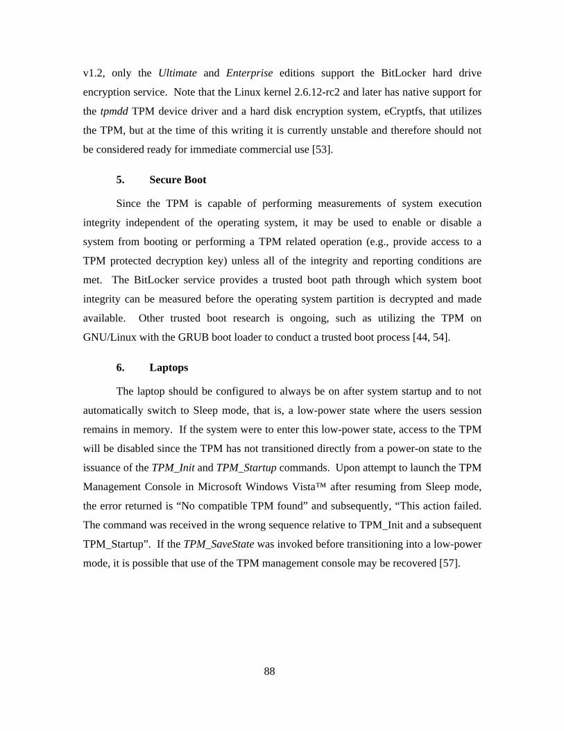
88
v1.2, only the Ultimate and Enterprise editions support the BitLocker hard drive
encryption service. Note that the Linux kernel 2.6.12-rc2 and later has native support for
the tpmdd TPM device driver and a hard disk encryption system, eCryptfs, that utilizes
the TPM, but at the time of this writing it is currently unstable and therefore should not
be considered ready for immediate commercial use [53].
5. Secure Boot
Since the TPM is capable of performing measurements of system execution
integrity independent of the operating system, it may be used to enable or disable a
system from booting or performing a TPM related operation (e.g., provide access to a
TPM protected decryption key) unless all of the integrity and reporting conditions are
met. The BitLocker service provides a trusted boot path through which system boot
integrity can be measured before the operating system partition is decrypted and made
available. Other trusted boot research is ongoing, such as utilizing the TPM on
GNU/Linux with the GRUB boot loader to conduct a trusted boot process [44, 54].
6. Laptops
The laptop should be configured to always be on after system startup and to not
automatically switch to Sleep mode, that is, a low-power state where the users session
remains in memory. If the system were to enter this low-power state, access to the TPM
will be disabled since the TPM has not transitioned directly from a power-on state to the
issuance of the TPM_Init and TPM_Startup commands. Upon attempt to launch the TPM
Management Console in Microsoft Windows Vista™ after resuming from Sleep mode,
the error returned is “No compatible TPM found” and subsequently, “This action failed.
The command was received in the wrong sequence relative to TPM_Init and a subsequent
TPM_Startup”. If the TPM_SaveState was invoked before transitioning into a low-power
mode, it is possible that use of the TPM management console may be recovered [57].

89
Figure 9 Sleep Mode Error for TPM on Microsoft Windows Vista™
7. Disk Encryption
It appears that the most popular use for TPMs currently is to provide a type of
hard drive encryption where the keys are protected by the TPM. In Microsoft Windows
Vista™, this is supported by the BitLocker service which is available in the Ultimate and
Enterprise editions of Vista. For GNU/Linux environments, the eCryptfs filesystem [12],
native in Linux kernel 2.6.19 and above, currently offers preliminary support for TPM
key storage [13]. The Enforcer security module for Linux released by Dartmouth in 2003
was use to provide file system integrity by using the TPM to store the key to an encrypted
loopback file system [17, 49], but at the time of this writing it appears to no longer be
under active development [69].
C. FUTURE WORK
While this thesis provides a preliminary investigation into the steps necessary to
establish a secure initialization of the TPM, much more work remains.
1. MANET Network Protocols Using TPMs
For the nodes to establish mutual authentication before participating in the
MANET, a common protocol must first be established. The design and implementation
of such a protocol will need to be secure against possible attacks. Therefore reuse of a
well established protocol is suggested. For example, the TLS/SSL two party mutual
authentication protocol for clients and servers could be used [10]. It could employ a
Diffie-Hellman method for the establishment of a session key [42]. The session key

90
would then be used by the two parties for all future communication. Performance and
traffic analysis of this implementation should be conducted to establish throughput,
scalability of session key negotiations, optimal session key lifetime, encryption and
decryption time and a cost-benefit analysis of its effect on routing if multiple encrypted
transmissions must be made of the same message to broadcast to all associated neighbors.
The generation of a single session key for use by each deployment is another option.
2. Multiple MANET Authorization
Sometimes a node needs to be associated with more than one MANET. Two
possible ways to achieve this are discussed here. First, the AIK Credential of a node may
state that it is authorized to associate with more than one MANET deployment name. By
using the X509v3 certificate format [11], any number of additional “Subject Alternate
Names” may be specified as an extension to the certificate. Each additional name could
correspond to a different MANET, and as long as the name appeared on the Credential,
the node would be authorized to associate with other nodes of that deployment. The
positive aspect of this option is that only one AIK Credential ever needs to be created and
distributed per node. One potential hazard is that now every other node also knows all of
the MANET deployments that the other nodes are authorized to access. One drawback to
this is the security and privacy concern of using one AIK identity for multiple domains.
A second possible solution is to generate multiple AIKs and have a different AIK
private key and AIK Credential for every MANET deployment the node wishes to
associate with. There is extra work involved in generating multiple AIK Credentials and
managing the additional keys, but the linking of an identity across multiple domains is
addressed. Under the current CONOP assumptions though, every deployment which the
node will be authorized to communicate with must be determined a priori at the Depot.

91
APPENDIX
A. TPM ASSUMPTIONS
As stated in the TCPA Trusted Platform Module (TPM) Protection Profile
(Version 1.9.7) [52], the two assumptions of the TPM include: 1) proper configuration
and 2) a physically secure environment. The TPM Assumptions in Table 35 have been
recreated from the TPM Protection Profile to include both the usage and environmental
assumptions [52]. For the assumption name in the table, the prefix “A” is used for an
assumption of the TPM and “AE” for an assumption of the environment in which it is
used. The Depot environment provides for the physical protection assumption. The
assumption names are used simply for ease of reference.
Table 35 TPM Assumptions # Assumption Name Description 1 A.Configuration The TPM will be properly installed and configured. 2 AE.Physical_Protection The TPM provides tamper evidence only. It provides no protection
against physical threats such as simple power analysis, differential power analysis, external signals, or extreme temperature. Physical protection is assumed to be provided by the environment.

92
B. TBB ASSUMPTIONS
The assumptions of the TBB Protection Profile [8] are defined in Table 36. There
is only one assumption of the environment for the TBB, which is prefixed with “AE” for
convention.
Table 36 TBB Assumptions # Assumption Name Description 1 AE.Certified_TPM The TPM connected to the TBB is a CC certified component, compliant
with the TCG TPM PP, and is present during any operation of the TBB.

93
C. TPM THREATS
In the TCPA TPM Protection Profile version 1.9.7, Section 3.2 “Threats to
Security” outlines all of the threats taken into consideration in the design of the TPM for
commercial use. These threats are presented here in Table 37 for reference [52].
Table 37 Threats to TPM Security # Threat Name Description
1 T.Attack An undetected compromise of the cryptography-related IT assets
may occur as a result of an attacker (whether an insider or outsider) attempting to perform actions that the individual is not authorized to perform.
2 T.Bypass An unauthorized individual or user may tamper with security attributes or other data in order to bypass TOE security functions and gain unauthorized access to TOE assets.
3 T.Export A user or an attacker may export data without security attributes or with unsecure security attributes, causing the data exported to be erroneous and unusable, to allow erroneous data to be added or substituted for the original data, and/or to reveal secrets.
4 T.Hack_Crypto Cryptographic algorithms may be incorrectly implemented, allowing an unauthorized individual or user to decipher keys generated within the TPM and thereby gain unauthorized access to encrypted data.
5 T.Hack_Physical An unauthorized individual or user of the TOE may cause unauthorized disclosure or modification of TOE assets by physically interacting with the TOE to exploit vulnerabilities in the physical environment.
6 T.Imperson An unauthorized individual may impersonate an authorized user of the TOE and thereby gain access to TOE data, keys, and operations.
7 T.Import A user or attacker may import data or keys without security attributes or with erroneous security attributes, causing key ownership and authorization to be uncertain or erroneous and the system to malfunction or operate in an unsecure manner.
8 T.Key_Gen_Destroy Cryptographic keys may be generated or destroyed in an unsecure manner, causing key compromise.
9 T.Malfunction TOE assets may be modified or disclosed to an unauthorized individual or user of the TOE, through malfunction of the TOE.
10 T.Modify An attacker may modify TSF or user data, e.g., stored security attributes or keys, in order to gain access to the TOE and its assets.
11 T.Object_Attr_Default A user may create an object with no security attribute values. 12 T.Object_Attr_Change A user or attacker may make unauthorized changes to security
attribute values for an object. 13 T.Object_SecureValues A user may set unsecure values for object security attributes. 14 T.Residual_Info A user may obtain information that the user is not authorized to
have when the data is no longer actively managed by the TOE (“data scavenging”).

94
15 T.Replay An unauthorized individual may gain access to the system and sensitive data through a “replay” or “man-in-the-middle” attack that allows the individual to capture identification and authentication data.
16 T.Repudiate_Transact An originator of data may deny originating the data to avoid accountability.
17 T.Test The TOE may start-up in an unsecure state or enter an unsecure state, allowing an attacker to obtain sensitive data or compromise the system.

95
D. TBB THREATS
The Security Threats to the TBB and the IT Environment, as identified in the
TBB Protection Profile, are contained in Tables 38 and 39. Those threats which pertain
to the TBB itself start with the naming convention “T.” while those threats in the IT
Environment begin with “TE.” followed by the threat name.
Table 38 TBB Threats # Threat Name Description 1 T.CRTM_Not_First An attacker may cause other code to be executed prior to executing
the CRTM code upon platform reset, thereby compromising the CRTM and causing the CRTM to become untrusted.
2 T.Failure An attacker may gain access to secrets by causing the connection to the TPM to fail.
3 T.Incorrect_CRTM An attacker may substitute a CRTM in the TOE, causing the CRTM to be invalidated and compromising the security of the data within the TPM.
4 T.Malfunction A malfunction of the TOE may cause modification of TOE assets or cause TOE assets to be disclosed.
5 T.Measure_Integrity The CRTM may fail to measure the integrity of the next component to execute and thereby cause a denial of service or a compromise of the security of data.
6 T.Physical An attacker may cause disclosure or modification of TOE assets by physically interacting with the TOE to exploit vulnerabilities in the physical environment.
7 T.Protect An operation external to the TOE may interfere with TOE security functions or resources, causing disclosure of TSF data or other errors to occur.
8 T.TPM_One_To_Many An attacker may disconnect the TPM from the platform and successfully reconnect the TPM with another platform, thereby compromising the security of the data within the TPM and invalidating the CRTM.
Table 39 TBB Environmental Threats # Environment
Threats Description
9 TE.Bypass An attacker may bypass environmental security functions and gain unauthorized access to TBB assets.
10 TE.Presence A remote attacker may cause the IT environment to pass an indication of physical presence to the TOE, thereby allowing the attacker to perform operations on the TPM that may only be performed when physically present at the platform.
4 TE.Reset The CPU may reset without the TPM reset, resulting in a set of invalid PCR values and denial of service or the TPM may reset without a CPU reset, resulting in a TPM with PCRs set to their initial state (i.e., the value 0), resulting in an untrusted root of trust.

96
E. TPM SECURITY OBJECTIVES
The security objectives of the TPM as identified in the TPM Protection Profile
[52] are identified in Tables 40 and 41. Those objectives which are addressed by the
TPM begin with an objective prefix “O” while those objectives addressed by the
environment begin with the prefix “OE” [52].
Table 40 Security Objectives of the TPM # Objective Name Description 1 O.Crypto_Key_Man The TPM shall generate and destroy cryptographic keys in a
secure manner. 2 O.Crypto_Op The TPM shall perform cryptographic operations, including
secure hash, HMAC, RSA digital signature and signature verification, RSA encryption and decryption, and RSA key generation in accordance with specified algorithms and key size; key size must be sufficient size to protect private/public key pairs from deciphering.
3 O.Crypto_Self_ The TPM shall provide the ability to verify that the cryptographic functions operate as designed.
4 O.DAC The TPM shall control and restrict user access to the TPM assets in accordance with a specified access control policy.
5 O.Export When data are exported outside the TPM, the TPM shall ensure that the data security attributes being exported are unambiguously associated with the data.
6 O.Fail_Secure The TPM shall preserve the secure state of the system in the event of a cryptographic or other failure.
7 O.General_Integ_Checks The TPM shall provide periodic checks on system integrity and user data integrity.
8 O.HMAC The TPM shall provide the ability to detect the modification of security attributes and other data.
9 O.I&A The TPM shall uniquely identify all users, and shall authenticate the claimed identify before granting a user access to the TPM facilities.
10 O.Import When data are being imported into the TPM, the TPM shall ensure that the data security attributes are being imported with the data and the data is from authorized source. In addition, the TPM shall verify those security attributes according to the TSF access control rules.
11 O.Invoke The TSF shall be invoked for all actions. 12 O.Limit_Actions_Auth The TPM shall restrict the actions a user may perform before
the TPM verifies the identity of the user. 13 O.MessageNR The TPM shall provide user data integrity, source
authentication, and the basis for source non-repudiation when exchanging data with a remote system.
14 O.No_Residual_Info The TPM shall ensure there is no “object reuse,” i.e., ensure that there is no residual information in information containers or system resources upon their reallocation to different users.
15 O.Object_Attr_Default The TPM shall require default security attributes for the object when the object is created.

97
16 O.Object_Attr_DefaultOver The TPM shall permit authorized users to override defaulted values for security attributes for an object.
17 O.Obj_Attr_SecureValues The TPM shall maintain object security attributes by permitting only secure values.
18 O.Security_Attr_Mgt The TPM shall allow only authorized users to initialize and change object security attributes.
19 O.Security_Roles The TPM shall maintain security-relevant roles and association of users with those roles.
20 O.Self_Protect The TSF will maintain a domain for its own execution that protects it and its resources from external interference, tampering, or unauthorized disclosure.
20 O.Single_Auth The TPM shall provide a single use authentication mechanism and require re-authentication to prevent “replay” and “man-in-the-middle” attacks.
21 O.Tamper_ID The TPM shall provide features that permit a human to detect physical tampering of a system component.
Table 41 Security Objectives of the TPM Environment # Environment
Objective Description
22 OE.Configuration The TPM shall be installed and configured properly for starting up the TPM in a secure state.
23 OE.PhysSecurity The environment shall provide an acceptable level of physical security so that the TPM cannot be tampered with or be subject to side channel attacks such as the various forms of power analysis and timing attacks.

98
F. TBB SECURITY OBJECTIVES
The security objectives of the TBB as identified in the TBB Protection Profile [8]
are identified in Tables 42 and 43.
Table 42 Security Objectives of the TBB # Objective Name Description 1 O.Correct_CRTM The Security Functions shall unambiguously associate the CRTM with
the TBB and the Security Functions shall enforce that the CRTM is the correct CRTM for the TBB.
2 O.CRTM_First The TBB shall ensure that the CRTM code is the first code executed upon platform reset.
3 O.Detect_Physical The TBB shall provide features that permit a human to detect at least one method of physical tampering with the TPM connection.
4 O.Fail_Secure The TBB shall preserve a secure state in the event of failure of the TPM connection.
5 O.Integrity The CRTM shall measure the integrity of the next component to execute and pass integrity data to the TPM.
6 O.One_To_One The TBB shall enforce a one-to-one relationship between the TPM and the Platform.
7 O.Secure_State The TBB shall maintain and recover to a secure state without security compromise after system error or other interruption of system operation.
8 O.Self_Protect The Security Functions shall maintain a domain for its own execution that protects it and its resources from external interference, tampering, or unauthorized disclosure.
Table 43 Security Objectives of the TBB Environment # Environment
Objective Description
9 OE.Certified_TPM The TPM included in the IT environment shall be a CC certified component, compliant with the TCG TPM PP and shall be present during any operation of the TBB.
10 OE.Invoke The IT Environment shall invoke IT Environmental security functions defined to support the TBB Security Policy.
11 OE.Presence The IT Environment shall pass an unambiguous indication of physical presence to the TBB.
12 OE.Reset The IT Environment shall ensure that the CPU and TPM are reset simultaneously and that the reset signal shall be derived from or initiated by the platform reset or power-on signal.

99
G. TPM REQUIREMENTS
The security requirements of the TPM as identified in the TPM Protection Profile
[52] are identified in Table 44. In the table, the requirement names and descriptions have
been adjusted slightly for the sake of readability and condensation of the material. “FIA”
for “Functional Identification and Authentication” “FTP” for “Functional Trusted
Path/Channels” “FPT” for “Functional Protection of Security Functions” “FMT” for
“Security Management” “FIA” for “Functional Identification and Authentication” “FDP”
for “Functional User Data Protection” “FCS” for “Functional Cryptographic Support”
“FCO” for Functional Communication”
Table 44 Security Requirements of the TPM # Functional
Requirement Description
1 FCO.NRO.2 Enforced proof of origin: 1) The TPM shall enforce the generation of evidence of origin for transmitted TPM data signed using identity keys at all times 2) The TPM shall be able to relate the identity of the originator of the information, and the TPM data of the information to which the evidence applies 3) TPM shall provide a capability to verify the evidence of origin of information to recipient given evidence only available when requestor properly authenticates
2 FCS.CKM.1 Cryptographic key generation: 1) The TPM shall generate cryptographic keys in accordance with a specified cryptographic key generation algorithm RSA and specified cryptographic key sizes RSA 512, 1024, 2048 that meet: PKCS#1 V2
3 FCS.CKM.4 Cryptographic key destruction: 1) The TPM shall destroy cryptographic keys in accordance with a specified cryptographic key destruction method erasure of memory areas containing cryptographic keys that meets the following: FIPS 140-1, Section 4.8.5, Key Destruction, or equivalent.
4 FCS.COP.1 Cryptographic operation, RSA encrypt and decrypt: 1) The TPM shall perform encryption and decryption in accordance with a specified cryptographic key generation algorithm RSA and specified cryptographic key sizes RSA 512, 1024, 2048 that meet: PKCS#1 V2 Cryptographic Operation, RSA signature and signature verification: 2) The TPM shall perform signature generation and signature verification in accordance with a specified cryptographic key generation algorithm RSA and specified cryptographic key sizes RSA 512, 1024, 2048 that meet: PKCS#1 V2 Cryptographic Operation, SHA 3) The TPM shall perform secure hash in accordance with a specified cryptographic algorithm SHA-1 and cryptographic key sizes not applicable that meet the following: FIPS 180-1. Cryptographic Operation, Keyed-Hashing for Message Authentication 4) The TPM shall perform keyed-hashing message authentication code (HMAC) in accordance with a specified cryptographic algorithm SHA-1 and cryptographic key sizes 160 bits that meet the following: RFC 2104.

100
5 FDP.ACC.1 Subset access control 1) The TPM shall enforce Protected Operations Access Controls on a) Subjects: commands executing on behalf of users b) Objects: keys and user data c) Operations: signature generation, encryption or decryption
6 FDP.ACF.1 Security attribute based access control 1) The TPM shall enforce Protected Operations Access Controls to objects based on security attributes TCPA_AUTH_DATA_USAGE, TCPA_KEY_FLAGS, and TCPA_KEY_USAGE 2) The TPM shall enforce the following rules to determine allowed use: a) Key and data access in defined as “owner” access or “world” based on the value of TCPA_AUTH_DATA_USAGE b) Cryptographic operations for each key are limited based on the specification of the TCPA_KEY_USAGE value 3) The TPM shall explicitly authorize access of subjects to objects based on the following additional rules: rules based on security attributes that explicitly authorize access of subjects to objects. 4) The TPM shall explicitly deny access of subjects to objects based on: rules based on security attributes that explicitly deny access of subjects to objects
7 FDP.ETC.2 Export of user data with security attributes: 1) The TPM shall enforce Protected Operations Access Controls when exporting user data, controlled under the security functional policy, outside of the scope of control. 2) The TPM shall export the user data with the user data’s associated security attributes. 3) The TPM shall ensure that the security attributes, when exported outside the TSC, are unambiguously associated with the exported user data. 4) The TPM shall enforce the following rules when user data is exported from the TSC: A key may be encrypted for migration only if the migratable flag is set in TCPA_KEY_FLAGS, [assignment: additional exportation control rules].
8 FDP.ITC.2 Import of user data with security attributes: 1) The TPM shall enforce the Protected Operations Access Controls when importing user data, controlled under the SFP, from outside of the TSC. 2) The TPM shall use the security attributes associated with the imported user data. 3) The TPM shall ensure that the protocol used provides for the unambiguous association between the security attributes and the user data received. 4) The TPM shall ensure that interpretation of the security attributes of the imported user data is as intended by the source of the user data. 5) The TPM shall enforce the following rules when importing user data controlled under the SFP from outside the TSC: [assignment: additional importation control rules].
9 FDP.RIP.2 Full residual information protection 1) The TPM shall ensure that any previous information content of a resource is made unavailable upon the de-allocation of the resource from all objects.
10 FIA.ATD.1 User attribute definition 1) The TPM shall maintain the following list of security attributes belonging to individual users: authentication data, role.

101
11 FIA.UAU.1 Timing of identification 1) The TPM shall allow access to data and keys where entity owner has given the “world” access based on the value of TCPA_AUTH_DATA_USAGE; access to the following commands: TPM_SelfTestFull, TPM_ContinueSelfTest, TPM_GetTestResult, TPM_PcrRead, TPM_DirRead, and TPM_EvictKey on behalf of the user to be performed before the user is authenticated.
12 FIA.UAU.4 Single-use authentication mechanism 1) The TPM shall prevent reuse of authentication data related to the use of the “Object-Independent Authorization Protocol” (OI-AP) and the “Object-Specific Authorization Protocol” (OS-AP) protocols.
13 FIA.UAU.6 Re-authenticating 1) The TPM shall re-authenticate the user under the conditions: for every command that requires user authentication.
14 FIA.UID.1 Timing of identification 1) The TPM shall allow access to data and keys where entity owner has given the “world” access based on the value of TCPA_AUTH_DATA_USAGE; access to the following commands: TPM_SelfTestFull, TPM_ContinueSelfTest, TPM_GetTestResult, TPM_PcrRead, TPM_DirRead, and TPM_EvictKey on behalf of the user to be performed before the user is identified. 2) The TPM shall require each user to be successfully identified before allowing any other TPM-mediated actions on behalf of that user.
15 FMT.MOF.1 Management of security functions behavior 1) The TPM shall restrict the ability to disable or enable the functions [assignment: list of functions] to the TPM owner.
16 FMT.MSA.1 Management of security attributes 1) The TPM shall enforce the Protected Operations Access Controls to restrict the ability to create the security attributes associated with a particular entity, including TCPA_KEY_USAGE, TCPA_AUTH_DATA_USAGE, migratable flag, and volatility flag to the entity owner.
17 FMT.MSA.2 Secure security attributes 1) The TPM shall ensure that only secure values are accepted for security attributes.
18 FMT.MSA.3 Static attribute initialization 1) The TPM shall enforce the Protected Operations Access Controls to provide specific default values for security attributes that are used to enforce the SFP. 2) The TPM shall allow the entity owner to specify alternative initial values to override the default values when an object or information is created.
19 FMT.MTD.1 Management of Security Functions data – TPM Owner modify 1) The TPM shall restrict the ability to modify the TPM data: Identification and authentication data associated with the Endorsement Key and SRK; Migration authorization data to the TPM Owner. TPM Owner create 1) The TPM shall restrict the ability to generate the TPM data: Storage Root Key and TPMProof to the TPM Owner. Entity Owner 1) The TPM shall restrict the ability to modify the TPM data: Identification and Authentication data associated with entity; to the entity Owner. Manufacturer 1) The TPM shall restrict the ability to generate the TPM data: Endorsement Key Pair to the TPM manufacturer or designee.

102
20 FMT.SMR.2 Restrictions on security roles 1) The TPM shall maintain the roles: TPM owner, owners of entities, and TPM manufacturer or designee. 2) The TPM shall be able to associate users with roles. 3) The TPM shall ensure that the condition: successful presentation of correct authentication data is satisfied.
21 FPT.AMT.1 Abstract machine testing 1) The TPM shall run a suite of tests during initial start-up and at the request of an authorized user to demonstrate the correct operation of the security assumptions provided by the abstract machine that underlies the TPM.
22 FPT.FLS.1 Failure with preservation of secure state 1) The TPM shall preserve a secure state when the following types of failures occur: failure of any crypto operations including RSA encryption, RSA decryption, SHA, RNG, RSA signature generation, HMAC generation; failure of any commands or internal operations.
23 FPT.PHP.1 Passive detection of physical attack 1) The TPM shall provide unambiguous detection of physical tampering that might compromise the TPM. 2) The TPM shall provide the capability to determine whether physical tampering with the TPM’s devices or TPM’s elements has occurred.
24 FPT.RCV.4 Function recovery 1) The TPM shall ensure that all TPM Commands have the property that the SF either completes successfully, or for the indicated failure scenarios, recovers to a consistent and secure state.
25 FPT.RPL.1 Replay detection 1) The TPM shall detect replay for the following entities: command requests that include the nonce parameter. 2) The TPM shall perform destroy session when replay is detected.
26 FPT.RVM.1 Non-bypassability of the Security Policy 1) The TPM shall ensure that TSP enforcement functions are invoked and succeed before each function within the TSC is allowed to proceed.
27 FPT.SEP.1 Security Function domain separation 1) The TPM shall maintain a security domain for its own execution that protects it from interference and tampering by untrusted subjects. 2) The TPM shall enforce separation between the security domains of subjects in the TSC.
28 FPT.TDC.1 Inter-Security Function basic data consistency 1) The TPM shall provide the capability to consistently interpret TPM commands and responses when shared between the TPM and another trusted IT product. 2) The TPM shall use the TCPA Main Specification when interpreting the TPM data from another trusted IT product.
29 FPT.TST.1 Security Function testing 1) The TPM shall run a suite of self tests during initial start-up and periodically during normal operation, at the request of the authorized user, and at the condition: prior to execution of the first call to a capability that uses those functions to demonstrate the correct operation of the TPM. 2) The TPM shall provide authorized users with the capability to verify the integrity of TPM data. 3) The TPM shall provide authorized users with the capability to verify the integrity of stored TPM executable code.

103
30 FTP.TRP.1 Trusted Path 1) The TPM shall provide a communication path between itself and local or remote users that is logically distinct from other communication paths and provides assured identification of its end points and protection of the communicated data from modification or disclosure. 2) The TPM shall permit the TPM, local or remote users to initiate communication via the trusted path. 3) The TPM shall require the user of the trusted path for initial user authentication, for all TPM commands, all user commands, and TPM responses.

104
H. TBB REQUIREMENTS
The Security Function Requirements of the TBB and its IT Environment have
been taken from the TBB Protection Profile and combined together in Tables 45 and 46.
In the table, the requirement names and descriptions have been adjusted slightly for the
sake of readability and condensation of the material. The prefix “FPT” in the functional
requirement name stands for “Functional Protection” and “FDP” stands for “Functional
Data Protection” [8].
Table 45 Security Requirements of the TBB # Functional
Requirement Description
1 FPT.Correct_CRTM CRTM is the correct CRTM: 1) unambiguously associate a CRTM with the TBB, 2) security functions enforce CRTM is correct one
2 FPT.Fail_Preserve Failure with preservation of a secure state: 1) TBB shall preserve a secure state when failures occur. (CRTM failure cannot be detected, but if initial measurement cannot be made, TPM access is denied)
3 FPT.CRTM_First CRTM first to execute: 1) CRTM shall be the first code executed upon platform reset.
4 FPT.Measure_Int Measures integrity of next component: 1) CRTM shall measure the BIOS code and data to which control will be passed, 2) CRTM shall perform an extend operation to record measurements before passing control to the next component. Control is only passed to the component that was hashed and extended.
5 FPT.One_To_One TPM associated one-to-one with platform: 1) There shall be a one-to-one relationship between the TPM and platform. A TPM removed from a motherboard must not be operational on another platform.
6 FPT.Indicate_Attack Indication of physical attack on the TPM connection: 1) The TBB security functions shall provide an unambiguous attack indication for at least one or more methods of physical tampering and 2) determine if tampering of the TPM connection has occurred (e.g., removal or replacement of TPM).
7 FPT.Func_Recovery Function recovery: 1) The TBB Security Functions such as communication with the TPM, failure of communication, and other capabilities shall return either a status of successful completion or an indication of failure and recover to a consistent and secure state.
8 FPT.Domain_Sep TBB Security Functions domain separation: 1) The TBB Security Functions shall maintain a security domain for its execution that protects it from interference and tampering by untrusted subjects and 2) enforce separation between the security domains of subjects

105
Table 46 Environment Requirements of the TBB # Environment
Objective Description
9 FDP_IPP.1 Indication of physical presence: 1) The IT Environment shall provide unambiguous indication of physical presence to the TBB. 2) The indication of physical presence shall come from the physical presence connection.
10 FPT_ENV_RST.1 Environment reset for CPU and TPM: 1) The IT Environment shall provide a reset signal and ensure that it causes the CPU and TPM to be reset simultaneously and 2) the reset signal shall be derived or initiated by the platform reset or power-on signal
11 FPT_RVM_ENV.1 Non-bypassability of the Security Functions: none

106
I. DEPOT MANAGEMENT PROCESS GUIDE
This appendix provides the implementation details of the depot management
process as outlined in Chapter V. For each of the steps identified below, the technical
details are provided on how to accomplish the task, and if possible, how to do so in
multiple environments such as the BIOS and operating system. This guideline is
intended to serve only as a supplement to more definitive resources [33-37] on TPM
management for the Depot System Administrator. This guide is written for a computing
environment consisting of Microsoft Windows Vista™ Business on the Dell™ Latitude
D820 laptop with a Broadcom TPM (A2) v1.2 and BIOS version A01. Administrator
rights are required on the platform to perform the following procedures and this guide
assumes the reader is well trained and familiar with system administration.
1. Clear the TPM
If there is already a TPM Owner installed on the TPM, then the TPM should be
cleared either from within the system BIOS or via the TPM Management Console if the
TPM Owner AuthData is available. The TPM Owner AuthData may be typed in or
provided as a file location when prompted to establish authorization to clear the TPM.
Proof of physical presence is demonstrated by accessing the BIOS at system startup to
establish authorization to clear the TPM if the Owner AuthData is lost. Table 46 provides
the directions on how to clear the TPM in different environments.
Table 47 Procedure to Clear the TPM
Environment Procedure
BIOS On Dell Latitude D820, during system boot up press F2 to enter the BIOS
Setup. On the left main menu, expand the Security tree and then select TPM Activation. If the TPM is currently owned, the option “Clear” will be displayed
in addition to “Deactivate” and “Activate” options. Select “Clear” and reboot.
Windows Vista™ Type Win+R to open the Run window and then type tpm.msc in the Open
field and click OK to launch the TPM Management Console (Figure 10). Click
on Continue if presented with the User Account Control dialogue box. In the
Actions pane on the right-hand side of the TPM Management Console, click
Clear TPM… to begin the Clear TPM process (Figure 11). A window will pop

107
up and ask if you would like to type in the TPM owner password or select a
file to which the TPM owner password was saved. In this case, click on “I want to type the TPM owner password” (Figure 12) and then you will be
prompted to enter it in the next window (Figure 13) and click Clear TPM…
This process will deactivate the TPM and remove ownership. (Figure 14)
Figure 10 Run the TPM Management Console
Figure 11 Clear TPM Via TPM Management Console

108
Figure 12 Clear the TPM with AuthData
Figure 13 Enter TPM Owner AuthData to Clear TPM

109
Figure 14 TPM Ownership Cleared
2. Disable the TPM
Since the hard disk initialization steps do not require use of the TPM, the TPM
can safely be disabled and deactivated. The directions for ensuring the TPM is disabled
and deactivated are provided in Table 48.
Table 48 Procedure to Disable the TPM
Environment Procedure
BIOS On Dell Latitude D820, during system boot up press F2 to enter the BIOS
Setup. On the left main menu, expand the Security tree and then select TPM Security. The options of “Off” and “On” are displayed. Select “Off”. (Figure
15) Also under the TPM Security menu, select TPM Activation. With no
ownership of the TPM, the options displayed are “Deactivate” and “Activate”.
Ensure “Deactivate” is selected then exit and reboot. (Figure 16)
Windows Vista™ There is no known physical presence assertion to “Disable” an unowned TPM
via the TPM Management Console on Windows Vista™.

110
Figure 15 Disable the TPM in the BIOS
Figure 16 Deactivate the TPM in the BIOS

111
3. Hard Disk Initialization
The hard disk reinitialization or the “zero-fill” process will erase the hard drive at
the lowest logical level, by writing a “0” to every sector of the disk such that all prior
data on the disk is lost, including file system and partition information. The operating
environment and “zero-fill” process will need to execute and run independent from the
drive to be erased, and this is usually done by booting from a utility CD provided by the
hard drive manufacturer. Table 49 describes the procedures to initialize a hard disk under
several operating environments.
Table 49 Procedure to Initialize the Hard Disk
Environment Procedure
Windows Vista™ In the Windows Preinstallation Environment, the diskpart utility used to
partition the disk can be used to write all zeros to it by running: diskpart clean all
Third Party It is very common to use third party software, such as a bootable utility CD
provided by the manufacturer of the hard drive to write zeros to the disk.
4. Partition and Format
The hard drive will need to be partitioned and formatted for use, though this can
often be done automatically during the operating system installation. For greater
flexibility and control, the Administrator may wish to perform these operations manually
for his or her own operating system environment. See Table 50 for instructions.
Table 50 Partition and Format Procedure
Environment Procedure
Windows Vista™ The system administrator may choose to partition and format the hard drive
directly after hard disk initialization or during the operating system installation.
From the Windows Pre-Boot Environment, the diskpart utility can be used
with a script to create the partitions and the format command can be used to

112
format them. If partitioning for use with BitLocker, two NTFS partitions will
need to be created. The first one from which the computer boots will need to
be at least 1.5GB and the operating system drive at least roughly 12GB. For
more details, see [30] for instructions.
5. Enable the TPM
The TPM should be enabled so that the hardware device is seen during the
installation of the new operating system. Since there is no ownership of the TPM at this
time and the operating system is not installed, physical presence will need to be
demonstrated in the BIOS in order to set the TPM to the Enabled and Deactivated state.
The procedure to enable the TPM in the system BIOS is presented in Table 51.
Table 51 Procedure to Enable the TPM
Environment Procedure
BIOS On Dell Latitude D820, during system boot up press F2 to enter the BIOS
Setup. On the left main menu, expand the Security tree and then select TPM Security. The options of “Off” and “On” are displayed. Select “On” as this
will “Enable” the TPM. Just under the TPM Security menu, select TPM Activation. With no ownership of the TPM, the options displayed are
“Deactivate” and “Activate”. Ensure “Deactivate” is still selected and reboot.
Windows Vista™ There is no known physical presence assertion to “Enable” an unowned TPM
via the TPM Management Console on Windows Vista™.
6. Install OS & Software
The operating system and any additional supporting software, such as a TPM
driver and a TCG Software Stack (TSS) from a third party, can be installed at this time
from trusted sources. All software configurations that do not require use of the TPM
should be done at this time since the TPM is not fully operational until ownership has
been taken. If any software requires use of the TPM, it should be configured after TPM
ownership has been taken.

113
7. Activate the TPM
The TPM needs to be both enabled and activated at this point. Since there is
currently no TPM owner, this operation must be performed and authorized by evidence of
physical presence. After a reboot, the TPM initialization process may begin and TPM
ownership taken. Table 52 provides the procedures for activating the TPM.
Table 52 Procedure to Activate the TPM
Environment Procedure
BIOS On Dell Latitude D820, during system boot up press F2 to enter the BIOS
Setup. On the left main menu, expand the Security tree and then select TPM Activation. With no ownership of the TPM, the options displayed are
“Deactivate” and “Activate”. Ensure “Activate” is selected and reboot.
Windows Vista™ There is no known physical presence assertion to “Activate” an unowned TPM
via the TPM Management Console on Windows Vista™.
8. Revoke TPM Trust
The capability to revoke TPM trust was not tested because it is not available in
the operating environment used in this thesis (e.g., Dell Latitude D820 with Microsoft
Windows Vista™ Business), either due to lack of support in the TPM hardware,
operating system or TSS.
9. Create EK
Since the capability to revoke TPM trust is not available in the example operating
environment used in this thesis (e.g., Dell Latitude D820 with Microsoft Windows
Vista™ Business), the capability to create a new EK for the TPM was also not tested.
10. Take Ownership
When the TPM is both Enabled and Activated with no TPM Owner currently set,
the TPM ownership may be taken. The process of taking ownership of the TPM is

114
sometimes referred to as “Initializing the TPM” since in essence, this process should only
need to happen once per system use lifecycle. Table 53 provides the procedures on how
to take ownership of the TPM.
Table 53 Procedure to Take Ownership of the TPM
Environment Procedure
Windows Vista™ Type Win+R to open the Run window and then type tpm.msc in the Open
field and click OK to launch the TPM Management Console (Figure 10). Click
on Continue if presented with the User Account Control dialogue box. In the
Actions pane on the right-hand side, click Initialize TPM… (Figure 17). A
pop up window will ask you to choose to automatically or manually create the
TPM password. Click on “Manually create the password” (Figure 18). In
the next window type in the TPM password twice and then click Initialize
(Figure 19). The initialization process will take a moment and then a window
will announce “Initialization completed”. Click on Close to close the window
(Figure 20) and verify that ownership has taken place (Figure 21).

115
Figure 17 Initialize TPM in TPM Management Console
Figure 18 Choose to Create TPM Owner Password

116
Figure 19 Type a TPM Owner Password
Figure 20 Initialization Completed

117
Figure 21 Ownership Completed in TPM Management Console
11. TPM Self-Test
Every time that a TPM-enabled system starts up, the TPM is designed to go
through a full self-test of its functional operation. If any error is encountered, the system
will fail to boot and issue a TPM Failed Self-Test error message. If the system does not
provide this error message, then it follows that the TPM passed the Self-Test on startup.

118
THIS PAGE INTENTIONALLY LEFT BLANK

119
LIST OF REFERENCES
[1] “Validated product - XTS-400 / STOP 6.1.E”, March 15, 2007; [Online]. Available: http://www.niap-ccevs.org/cc-scheme/st/ST_VID3012.cfm [Accessed May 31, 2007].
[2] “Consistency Instruction Manual for Medium Robustness Environments”, Feb. 1,
2005; [Online]. Available: http://www.niap-ccevs.org/pp/med_rob_manual-3.0.pdf [Accessed May 30, 2007].
[3] “CCEVS: Robustness Frequently Asked Questions (FAQ),” [Online]. Available:
http://www.niap-ccevs.org/cc-scheme/faqs/faqs-robustness.cfm [Accessed May 30, 2007] .
[4] H. Berghel and J. Uecker, "WiFi attack vectors," Comm. ACM, vol. 48, pp. 21-28,
Aug. 2005. 2005. [5] A. Bittau, M. Handley and J. Lackey, "The Final Nail in WEP's Coffin," SP. IEEE
Computer Society, pp. 386-400, May 21 - 24, 2006. 2006. [6] J. Cache, H. Moore and skape, “Exploiting 802.11 Wireless Driver Vulnerabilities on
Windows,” Nov. 2006; [Online]. Available: http://uninformed.org/index.cgi?v=6&a=2 [Accessed June 6, 2007].
[7] C. E. Chow, P. J. Fong and G. Godavari, "An exercise in constructing secure mobile
ad hoc network (SMANET)," in AINA '04: Proceedings of the 18th International Conference on Advanced Information Networking and Applications, 2004, pp. 436.
[8] “Trusted Computing Group (TCG) Personal Computer (PC) Specific Trusted
Building Block (TBB) Protection Profile and TCG PC Specific TBB with Maintenance Protection Profile,” July 20, 2004; [Online]. Available: http://www.niap-ccevs.org/cc-scheme/pp/PP_TCGPCTBB_V2.5.cfm [Accessed May 30, 2007].
[9] S. Corson and J. Macker. Mobile Ad-hoc networking (MANET): Routing Protocol
Performance Issues and Evaluation Consideration, IETF RFC 2501, Jan. 1999; http://tools.ietf.org/html/rfc2501.
[10] T. Dierks and E. Rescorla. The Transport Layer Security (TLS) Protocol version
1.1., IETF RFC 4346, Apr. 2006; http://tools.ietf.org/html/rfc4346. [11] DoD Public Key Infrastructure Program Management Office, "X.509 Certificate
Policy for the United States Department of Defense" 2007, 9 Feb 2005.

120
[12] eCryptfs. [Online]. Available: http://ecryptfs.sourceforge.net/ [Accessed May 30, 2007].
[13] TPM Keyring - eCryptfs Setup Guide. [Online]. Available:
http://trousers.sourceforge.net/tpm_keyring2/ecryptfs.html [Accessed May 30, 2007].
[14] J. Ellch. “Fingerprinting 802.11 Dvices,” Master’s Thesis, Naval Postgraduate
School, Monterey, California, 2007. [15] S. R. Fluhrer, I. Mantin and A. and Shamir, "Weaknesses in the key scheduling
Algorithm of RC4," in Lecture Notes in Computer Science , vol. 2259, S. Vaudenay and A. M. Youssef, Eds. London: Springer-Verlag, pp. 1-24.
[16] J. Franklin, et al. “Passive Data Link Layer 802.11 Wireless Device Driver
Fingerprinting,” in Proceedings of USENIX Security 2006. [Online]. Available: http://www.sandia.gov/news/resources/releases/2006/images/wireless-fingerprinting.pdf [Accessed May 30, 2007].
[17] M. Franklin, K. Mitcham, S. Smith, J. Stabiner and O. Wild, “CA-in-a-box,”
[Online]. Available: http://www.ists.dartmouth.edu/library/131.pdf [Accessed May 30, 2007].
[18] K. Goldman, R. Perez and R. Sailer, "Linking remote attestation to secure tunnel
endpoints," in Proceedings of the First ACM Workshop on Scalable Trusted Computing, 2006, pp. 21-24.
[19] R. Housley, W. Polk, W. Ford and D. Solo. Internet X.509 Public Key
Infrastructure Certificate and Certificate Revocation List (CRL) Profile, IETF RFC 3280, April 2002; http://tools.ietf.org/html/rfc3280.
[20] IETF Secretariat, “Mobile Ad-hoc Networks (MANET) Charter,” Apr. 2, 2007;
[Online]. Available: http://www.ietf.org/html.charters/manet-charter.html [Accessed May 30, 2007].
[21] Intel Corporation, “Intel® Centrino Wireless Driver Malformed Frame Remote Code
Execution,” Jan. 12, 2007; [Online]. Available: http://security-center.intel.com/advisory.aspx?intelid=INTEL-SA-00001&languageid=en-fr [Accessed May 30, 2007].
[22] Irvine C. E., Nguyen T. D. and and Levin, T. E. “High Assurance Testbed for
Multilevel Interoperability,” Oct. 2004; [Online]. Available: http://cisr.nps.navy.mil/downloads/nps_cs_05_002.pdf [Accessed May 30, 2007].

121
[23] P. Judge. WiFi fingerprints Could End MAC Spoofing. Sep. 5, 2006. [Online]. Available: http://www.techworld.com/mobility/news/index.cfm?newsID=6787 [Accessed May 30, 2007].
[24] K.A. Remley, et al. “Electromagnetic Signatures of WLAN Cards and Network
Security,” [Online]. Available: http://csrc.nist.gov/manet/On802ElectromagneticSignatures-NIST.pdf [Accessed May 30, 2007].
[25] C. Kaufman, R. Perlman and M. Speciner, Network Security: Private
Communications in a Public World. New Jersey: Prentice-Hall, 1995, pp. 196-197.
[26] M. Kiaer, "A best practice guide on how to configure BitLocker (Part 1)," Jan. 23,
2007; [Online] Available: http://www.windowsecurity.com/articles/Best-practice-guide-how-configure-BitLocker-Part1.html [Accessed May 30, 2007].
[27] J. Kong, P. Zerfos, H. Luo and S. Lu, "Providing robust and ubiquitous security
support for mobile ad-hoc networks," in Ninth International Conference on Network Protocols, 2001, 2001, pp. 251-260.
[28] B. Krebs, “Hijacking a Macbook in 60 Seconds or Less,” March 31, 2007; [Online].
Available: http://blog.washingtonpost.com/securityfix/2006/08/hijacking_a_macbook_in_60_seco_1.html [Accessed May 30, 2007].
[29] Marco Domenico Aime, G. Calandriello and A. Lioy, "Dependability in Wireless
Networks: Can We Rely on WiFi?" IEEE Security and Privacy, vol. 5, pp. 23-29, 2007.
[30] D. Maynor, Apple info…and that’s all folks, March 2, 2007; [Online]. Available:
http://erratasec.blogspot.com/2007/03/apple-infoand-thats-all-folks.html [Accessed May 30, 2007].
[31] Microsoft Corporation,Hardware Requirements for BitLocker Drive Encryption.
[Online]. Available: http://windowshelp.microsoft.com/Windows/en-US/Help/a93aee6b-c329-4d52-9f13-a8588fc9510e1033.mspx [Accessed April 28, 2007].
[32] Microsoft Corporation, Trusted Platform Module Administrative Technical
Overview. [Online]. Available: http://technet2.microsoft.com/WindowsVista/en/library/39c4ff05-0c21-42c5-bbf6-fd500335b8b91033.mspx[Accessed April 28, 2007].

122
[33] Microsoft Corporation, Best Practices for Trusted Platform Module Management. [Online]. Available: http://www.microsoft.com/whdc/system/platform/hwsecurity/TPMBestPrac.mspx [Accessed April 28, 2007].
[34] Microsoft Corporation, How Do I Use Active Directory for Backup of BitLocker
Drive Encryption Recovery Information? [Online]. Available: http://windowshelp.microsoft.com/Windows/en-US/Help/86136f63-2f2f-40ad-a0d1-8293f4dbfc951033.mspx [Accessed April 28, 2007].
[35] Microsoft Corporation, Windows BitLocker Drive Encryption Step-by-Step Guide.
[Online]. Available: http://go.microsoft.com/fwlink/?linkid=53779 [Accessed April 23, 2007].
[36] Microsoft Corporation., Windows Trusted Platform Module Management Step-by-
Step Guide. [Online]. Available: http://go.microsoft.com/fwlink/?linkid=67232 [Accessed April 23, 2007].
[37] Microsoft Corporation, “Windows BitLocker Drive Encryption Frequently Asked
Questions”. [Online]. Available: http://technet2.microsoft.com/WindowsVista/en/library/58358421-a7f5-4c97-ab41-2bcc61a58a701033.mspx [Accessed April 23, 2007].
[38] M. Narasimha, G. Tsudik and J. H. Yi, "On the Utility of Distributed Cryptography
in P2P and MANETs: The Case of Membership Control,” INCP 2003, pp. 336-345, 2003.
[39] National Institute of Standards and Technology. The keyed-Hash Message
Authentication Code (HMAC), March 6, 2002; [Online]. Available: http://csrc.nist.gov/publications/fips/fips198/fips-198a.pdf [Accessed May 30, 2007].
[40] T. D. Nguyen, T. E. Levin and C. E. Irvine, "MYSEA Testbed," in Man and
Cybernetics Information Assurance Workshop, 2005, pp. 438-439. [41] C. Percival, “Cache Missing for Fun and Profit,” [Online]. Available:
http://www.daemonology.net/papers/htt.pdf [Accessed May 30, 2007]. [42] E. Rescorla, Diffie-Hellman Key Agreement Method, IETF RFC 2631, June 1999;
http://tools.ietf.org/html/rfc2631. [43] A. Sadeghi, M. Selhorst and C. Stuble, “TCG inside? A note on TPM Specification
Compliance”, May 2006; [Online]. Available: http://www.prosec.rub.de/docu/TPMcompliance.pdf [Accessed May 30, 2007].

123
[44] R. Sailer, T. Jaeger, X. Zhang and L. van Doorn, "Attestation-Based Policy Enforcement for Remote Access," in Proceedings of the 11th ACM Conference on Computer and Communications Security, 2004, pp. 308-317.
[45] L. Sarmenta, “TPM/J java-based API for the Trusted Platform Module (TPM)”, Apr. 3, 2007; [Online]. Available: http://projects.csail.mit.edu/tc/tpmj/ [Accessed May 30, 2007].
[46] N. Saxena, G. Tsudik and J. H. Yi, "Identity-based Access Control for Ad-hoc
Groups," in Lecture Notes in Computer Science, May 24, 2005; [Online]. Available: http://www.springerlink.com/content/ry0jqxaveb598fee.
[47] N. Saxena, G. Tsudik and J. H. Yi, "Admission control in Peer-to-Peer: design and
performance evaluation," pp. 104-113, 2003. [48] A. Shamir and N. van Someren, “Playing Hide and Seek with Stored Keys”,
[Online]. Available: http://hawaii.ms11.net/keyhide2.pdf [Accessed May 30, 2007].
[49] S. Smith, Trusted Computing Platforms: Design and Applications. New York, NY:
Springer Science+Business Media, Inc, 2005. [50] TPM Manager, [Online]. Available: http://sourceforge.net/projects/tpmmanager/
[Accessed May 30, 2007]. [51] F. Stumpf, O. Tafreschi, P. Röder and C. Eckert, “A Robust Integrity Reporting
Protocol for Remote Attestation”, Nov. 30, 2006; [Online]. Available: http://www.trl.ibm.com/projects/watc/FredericStumpfPaper.pdf [Accessed May 30, 2007].
[52] TPM Membership. “Computing Platform Alliance (TCPA) Trusted Platform Module
Protection Profile,” [Online]. Available: http://www.commoncriteriaportal.org/public/files/ppfiles/PP_TCPATPMPP_V1.9.7.pdf [Accessed May 30, 2007].
[53] “TPM Keyring – Quickstart Guide,” [Online]. Available:
http://trousers.sourceforge.net/tpm_keyring2/quickstart.html [Accessed Apr. 28, 2007].
[54] “GRUB TCG Patch to Support Trusted Boot,” [Online]. Available:
http://trousers.sourceforge.net/grub.html [Accessed Apr. 28, 2007.] [55] “Trousers: TCG Software Stack for Linux,” [Online]. Available:
http://trousers.sourceforge.net/ [Accessed May 30, 2007].

124
[56] Trusted Computing Group, “TCG Specification Architecture Overview,” [Online]. Available: https://www.trustedcomputinggroup.org/groups/TCG_1_3_Architecture_Overview.pdf [Accessed May 30, 2007].
[57] Trusted Computing Group, “TPM Main Part 1 Design Principles,” March 29, 2007;
[Online]. Available: https://www.trustedcomputinggroup.org/specs/TPM/Main_Part1_Rev94.zip [Accessed May 30, 2007].
[58] Trusted Computing Group, “TCG Trusted Network Connect, TNC Architecture for
Interoperability Specification,” May 1, 2006; [Online]. Available: https://www.trustedcomputinggroup.org/specs/TNC/TNC_Architecture_v1_1_r2.pdf [Accessed May 30, 2007].
[59] Trusted Computing Group. “TCG Software Stack (TSS) Specification, level 1: Part
1: Commands and Structures,” Jan. 6, 2006; [Online]. Available: https://www.trustedcomputinggroup.org/specs/TSS/TSS_Version_1.2_Level_1_FINAL.pdf [Accessed May 30, 2007].
[60] Trusted Computing Group, “TCG PC Client Specific Implementation Specification
for Conventional BIOS,” July 13, 2005; [Online]. Available: https://www.trustedcomputinggroup.org/specs/PCClient/TCG_PCClientImplementationforBIOS_1-20_1-00.pdf [Accessed May 30, 2007] .
[61] Trusted Computing Group, “TCG PC Client Specific TPM Interface Specification
(TIS),” July 11, 2005; [Online]. Available: https://www.trustedcomputinggroup.org/groups/pc_client/TCG_PCClientTPMSpecification_1-20_1-00_FINAL.pdf [Accessed May 30, 2007].
[62] Trusted Computing Group, “TCG Generic Server Specification,” March 23, 2005;
[Online]. Available: https://www.trustedcomputinggroup.org/specs/Server/TCG_Generic_Server_Specification_v1_0_rev0_8.pdf [Accessed May 30, 2007].
[63] Trusted Computing Group, “Open Standards for Integrity-based Network Access
Control,” [Online]. Available: https://www.trustedcomputinggroup.org/groups/network/Open_Standards_for_IntegrityBased_AccessControl.pdf [Accessed May 30, 2007].
[64] Trusted Computing Group, “TCG Glossary of Technical Terms,” [Online].
Available: https://www.trustedcomputinggroup.org/groups/glossary/ [Accessed May 30, 2007].

125
[65] Trusted Computing Group, “About the Trusted Computing Group,” [Online]. Available: https://www.trustedcomputinggroup.org/about/ [Accessed May 30, 2007].
[66] “Trusted Java,” [Online]. Available: http://trustedjava.sourceforge.net/ [Accessed
May 30, 2007]. [67] R. Vernon, "A Design for Sensing the Boot Type of a Trusted Platform Module
Enabled Computer," Master’s thesis, Naval Postgraduate School, Monterey, California, 2005.
[68] Wikipedia Contributors, “List of Ad-hoc Routing Protocols,” [Online]. Available:
http://en.wikipedia.org/w/index.php?title=List_of_ad-hoc_routing_protocols&oldid=119012650 [Accessed May 30, 2007].
[69] O. Wild, “Enforcer Linux Security Module”, Apr. 4, 2007; [Online]. Available:
http://enforcer.sourceforge.net/ [Accessed May 30, 2007]. [70] K. Yongdae, D. Mazzocchi and G. Tsudik, “Admission Control in Peer Groups,” in
Proceedings of the Second IEEE International Symposium on Network Computing and Applications (NCA’03), 2003.

126
THIS PAGE INTENTIONALLY LEFT BLANK

127
INITIAL DISTRIBUTION LIST
1. Defense Technical Information Center Ft. Belvoir, VA 2. Dudley Knox Library Naval Postgraduate School Monterey, CA 3. Hugo A. Badillo NSA Fort Meade, MD 4. George Bieber OSD Washington, DC 5. John Campbell
National Security Agency Fort Meade, MD
6. Deborah Cooper
DC Associates, LLC Roslyn, VA
7. Louise Davidson
National Geospatial Agency Bethesda, MD
8. Steve Davis
NRO Chantilly, VA
9. Vincent J. DiMaria National Security Agency Fort Meade, MD
10. Dr. Diana Gant
National Science Foundation 11. Jennifer Guild
SPAWAR Charleston, SC

128
12. Steve LaFountain NSA Fort Meade, MD 13. Dr. Greg Larson IDA Alexandria, VA 14. Dr. Karl Levitt
NSF Arlington, VA
15. Dr. Vic Maconachy
NSA Fort Meade, MD
16. Dr. John Monastra
Aerospace Corporation Chantilly, VA
17. John Mildner
SPAWAR Charleston, SC
18. Mark T. Powell Federal Aviation Administration Washington, DC 19. Jim Roberts
Central Intelligence Agency Reston, VA 20. Keith Jarren
NSA Fort Meade, MD
21. Ed Schneider IDA Alexandria, VA 22. Keith Schwalm
Good Harbor Consulting, LLC Washington, DC

129
23. Ken Shotting NSA Fort Meade, MD
24. CDR Wayne Slocum
SPAWAR San Diego, CA
25. Dr. Ralph Wachter ONR Arlington, VA 26. Dr. Cynthia E. Irvine Naval Postgraduate School Monterey, CA 27. Thuy D. Nguyen Naval Postgraduate School Monterey, CA 28. Dr. Blaine Burnham University of Nebraska at Omaha Omaha, NE 29. Brian Wiese Civilian, Naval Postgraduate School Monterey, CA