preliminary design review - mechanisms designirtfweb.ifa.hawaii.edu/.../5_mechanisms_bonnet.pdf ·...
TRANSCRIPT

1
Preliminary Design Review - Mechanisms Design -
iSHELL Preliminary Design Review: Mechanisms
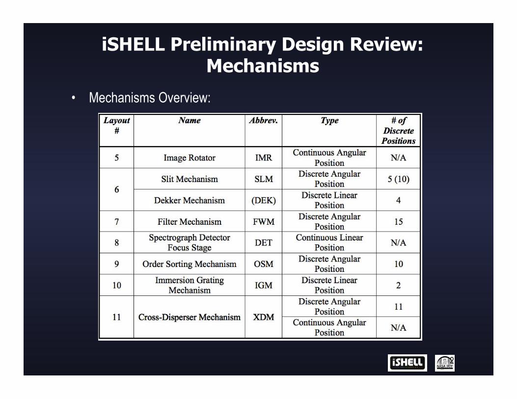
• Mechanisms Overview:
2

iSHELL Preliminary Design Review: Mechanisms
• High-Level Requirements:
3
Mechanism Temp Type Range Repositioning precision Element size CB mirror ~280 K In/out 2 positions ± 0.5 mm Beam Gas cell ~280 K In/out 2 positions ± 0.5 mm Beam Window cover ~280 K In/out 2 positions ± 0.5 mm Beam K-mirror 75 K Continuous > 360 degrees ± 0.1 deg on sky (1 pixel) Beam Slit wheel 75 K Detent 5 positions ± 1 pixel 30 mm diameter
5 mm thick Dekker stage 75 K Detent 4 positions ± 1 pixel n/a SV filter wheel 75 K Detent 15 positions ± 0.1 mm 25 mm diameter
~5 mm thick Order sorter wheel 75 K Detent 10 positions ± 0.1 mm 6 x 10 mm
~3 mm thick IG selection mirror 75 K In/out 2 positions ± 0.1 mm Beam XD wheel 75 K Detent 12 positions ± 1 pixel (15 arcsec) ~32 x 50 mm to
~32 x 40 mm ~ 7 mm thick
XD wheel tilt 75 K Continuous ± 5 degrees ± 1 pixel (15 arcsec) n/a Spectrograph focus 75 K Continuous ± 2 mm ± 50 µm n/a

4
GENERIC BEARING MOUNT

Athermal Bearing Mount
5

Athermal Turret Axle Design
6

Athermal Turret Behavior
7
• Components contract as turret cools from ambient to operating temperature
• Aluminum turret & axle contract/expand as a rigid body

Athermal turret axle design
8
• Eliminates axial & radial displacement of turret relative to axle
due to CTE mismatches between steel bearings and aluminum turret during cool-down/warm-up.
• Turret/axle assembly (CTE) behaves as though it were a single material as temperature changes
• Turret remains aligned when warm or cold
• Don’t need to design in “warm” bearing clearances that makes turret sloppy when warm & tight when cold
9
DISCRETE ANGULAR POSITION MECHANISMS
(DAPM)

DAPM: Choice of a type of wheel
10
Here is a summary of the pros and cons of a Geneva drive versus a compliant worm drive:
• Pro: Geneva mechanisms locate the wheel close to the required position => less detent force required
• Pro: Geneva mechanisms require less time to index than a worm drive because the reduction ration is usually less
• Con: Geneva mechanisms usually require the use of gear reduction. • Con: due to the reduction and the use of a cam, Geneva mechanisms
have more moving parts than a worm drive • Pro: Geneva wheels are less expansive to fabricate than worm drives • Con: Geneva mechanisms are limited in the number of discrete
positions.

11
DAPM: The Modified Geneva
DAPM: The Modified Geneva
12
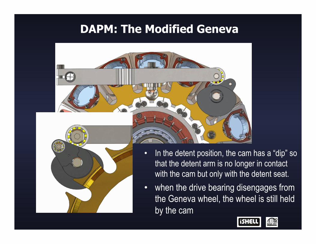
• In the detent position, the cam has a “dip” so that the detent arm is no longer in contact with the cam but only with the detent seat.
• when the drive bearing disengages from the Geneva wheel, the wheel is still held by the cam

13
• Zone 1 - Ramp up • Follower travels from fully seated
position to fully disengaged position • Zone 2 – Constant speed • Crank engages with the Geneva slot
Turret gets moved to the next position
• Crank disengages with the Geneva slot
• Zone 3 – Ramp down • Follower lowers back down and
detent seats in V-groove of the next turret position to locate turret.
DAPM: The Modified Geneva

DAPM: The Modified Geneva
14
Geneva Drive Motor Loads For 1 Cycle:
DAPM: Slit Wheel + Order Sorter
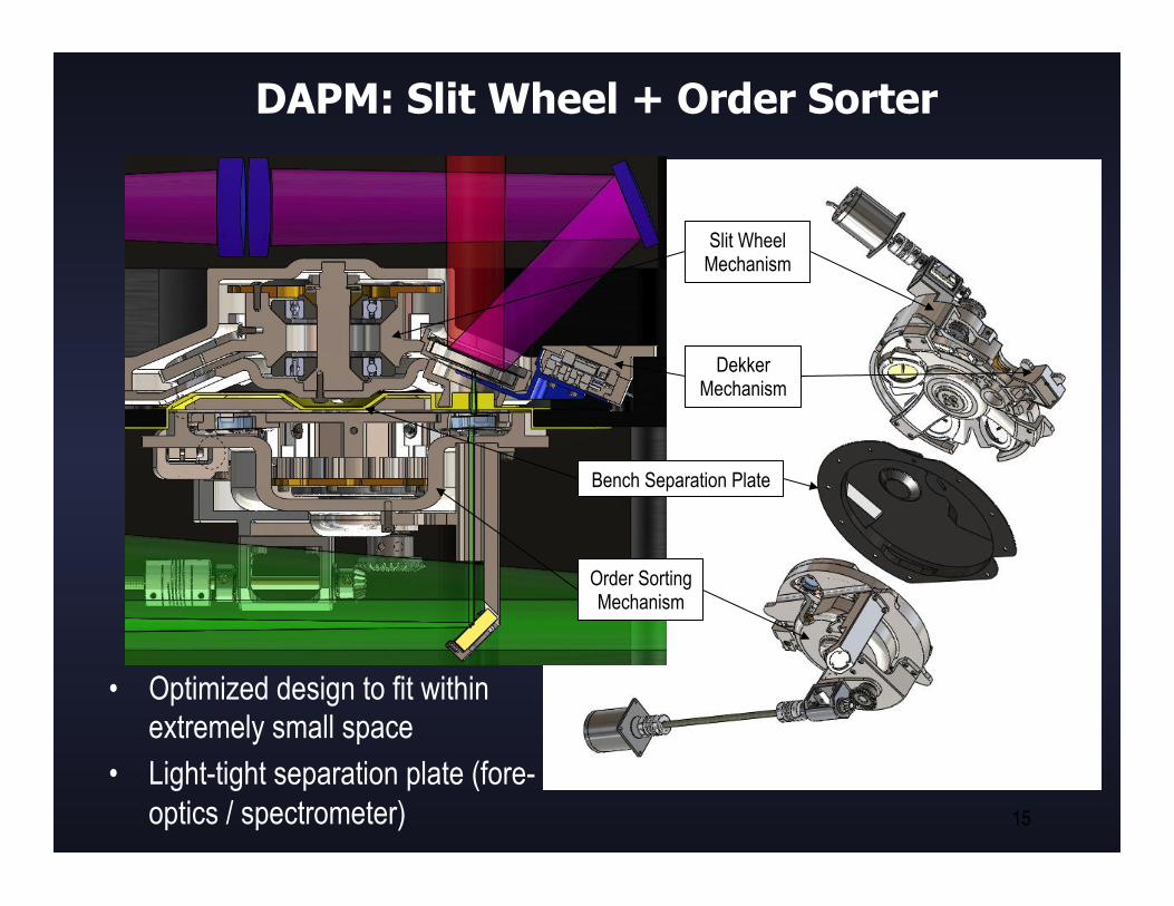
• Optimized design to fit within extremely small space
• Light-tight separation plate (fore-optics / spectrometer)
15
Order Sorting Mechanism
Slit Wheel Mechanism
Bench Separation Plate
Dekker Mechanism
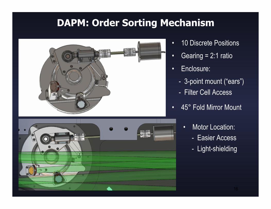
DAPM: Order Sorting Mechanism
• 10 Discrete Positions • Gearing = 2:1 ratio • Enclosure: - 3-point mount (“ears”) - Filter Cell Access
• 45° Fold Mirror Mount
16
• Motor Location: - Easier Access - Light-shielding

DAPM: Slit Wheel Mechanism
• 5 (10) Discrete Positions • Gearing = 2:1 ratio • Enclosure: - 3-point mount (“ears”) - Slit Mirror Cell Access
• “light seal” around the Dekker mask.
• 22.5deg conical turret -> axle // to OSM axle
17

DAPM: Slit Wheel Mechanism
18

DAPM: Filter Wheel Mechanism
• 15 Discrete Positions • Gearing: 1:1 Bevel + 4:1
Phytron Planetary Gear • 45deg Turret for optimized
space usage • Light-tight Motor Mount
19

DAPM: Filter Wheel Mechanism
20
• Filter Cells Facilitate swap/replacement of filters • 3-point support = Statically Determinate • 2 different Cells with 2 different angles (Ghost)

DAPM: Filter Wheel Mechanism
21
Motor Mount Concept:
Cross-Section
Light-Shield Cold-Strap
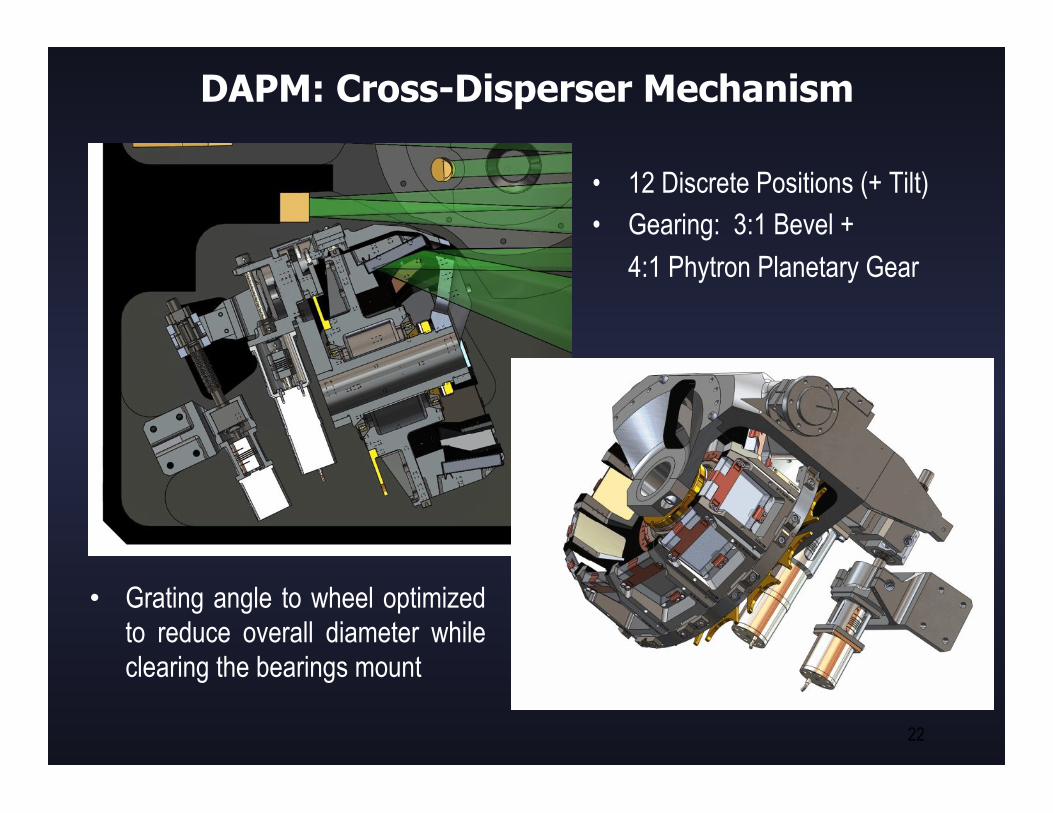
DAPM: Cross-Disperser Mechanism
• 12 Discrete Positions (+ Tilt) • Gearing: 3:1 Bevel +
4:1 Phytron Planetary Gear
22
• Grating angle to wheel optimized to reduce overall diameter while clearing the bearings mount

DAPM: Cross-Disperser Mechanism
23
• Gratings are mounted in removable
modules • Optics modules are unique but are
machined from identical blanks.
• Each grating is mounted in a module with mounting features that fully support the grating without over constraining it.
• The grating modules have no provisions for tip/tilt adjustment. One-time adjustments may be necessary by machining optics mounting surfaces.

24
CONTINUOUS ANGULAR POSITION MECHANISMS
(CAPM)

CAPM: Image Rotator
• Designed by G. Muller • First Concept
25
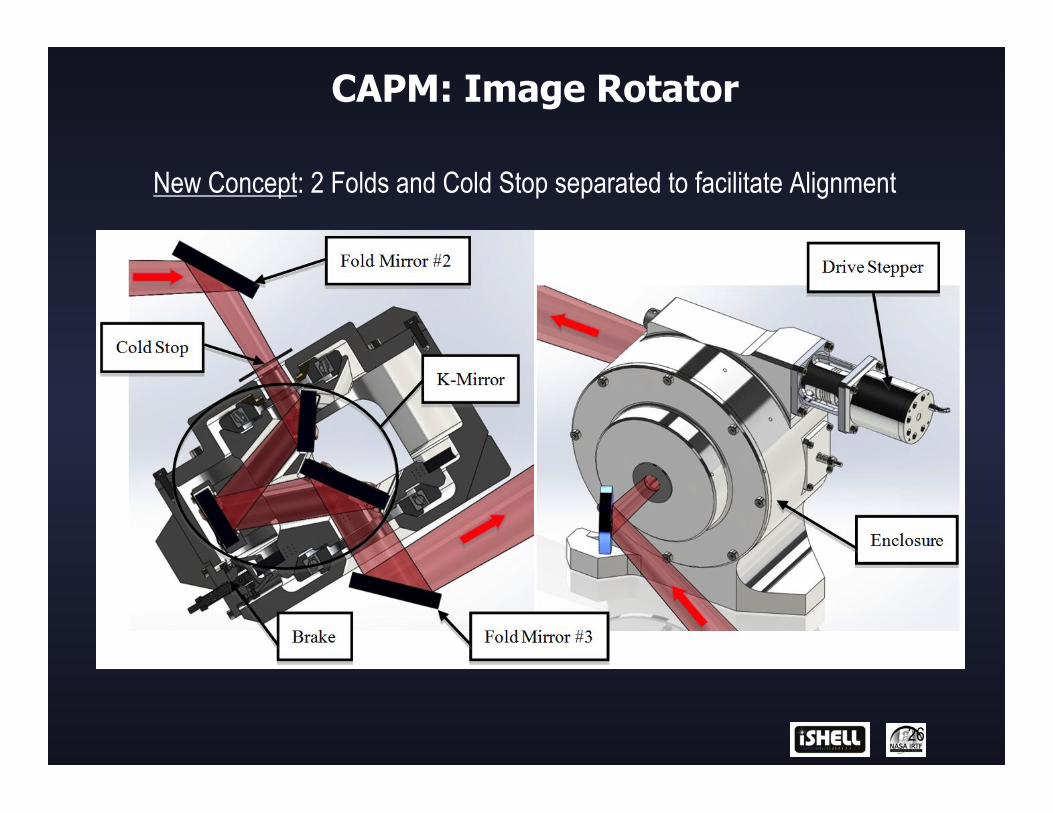
CAPM: Image Rotator
26
New Concept: 2 Folds and Cold Stop separated to facilitate Alignment

CAPM: Image Rotator
27
K-Mirror Assembly and K-Mirror Hub:
Note: The middle mirror of the K-mirror assembly is separated from the main hub because it would be very difficult to fabricate as one part.

CAPM: Image Rotator Drive
28
a) 120 tooth brass worm gear b) Hall effect sensor c) Vespel worm d) Drive shaft bearing e) Flex coupling f) Stepper motor
• Home position determined by state change of Hall-effect sensor (i.e. sense to not sense, but not vice versa)
• Count steps from home to determine position (Requires initialization procedure at startup)
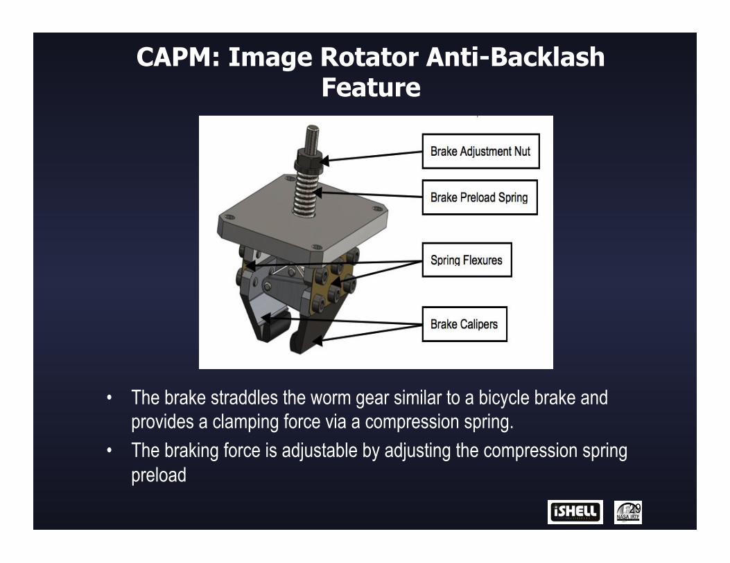
CAPM: Image Rotator Anti-Backlash Feature
29
• The brake straddles the worm gear similar to a bicycle brake and provides a clamping force via a compression spring.
• The braking force is adjustable by adjusting the compression spring preload

CAPM: Cross-Disperser Tilt Mechanism
30

CAPM: Cross-Disperser Tilt Control
• Choice of a type of position sensor: 1. Hall Effect Sensor (F.W. Bell FH-301-040) : � 2. Eddy Current Sensor (Kaman DIT-5200L / 20N): !
31
VS
(*) The “Physical Range Reduction Trick” Can only be used with an active sensor and a passive target (aluminum). See Next Slide.

CAPM: Cross-Disperser Tilt Control
32

33
DISCRETE LINEAR POSITION MECHANISMS
(DLPM)
DLPM: Dekker Mechanism
34
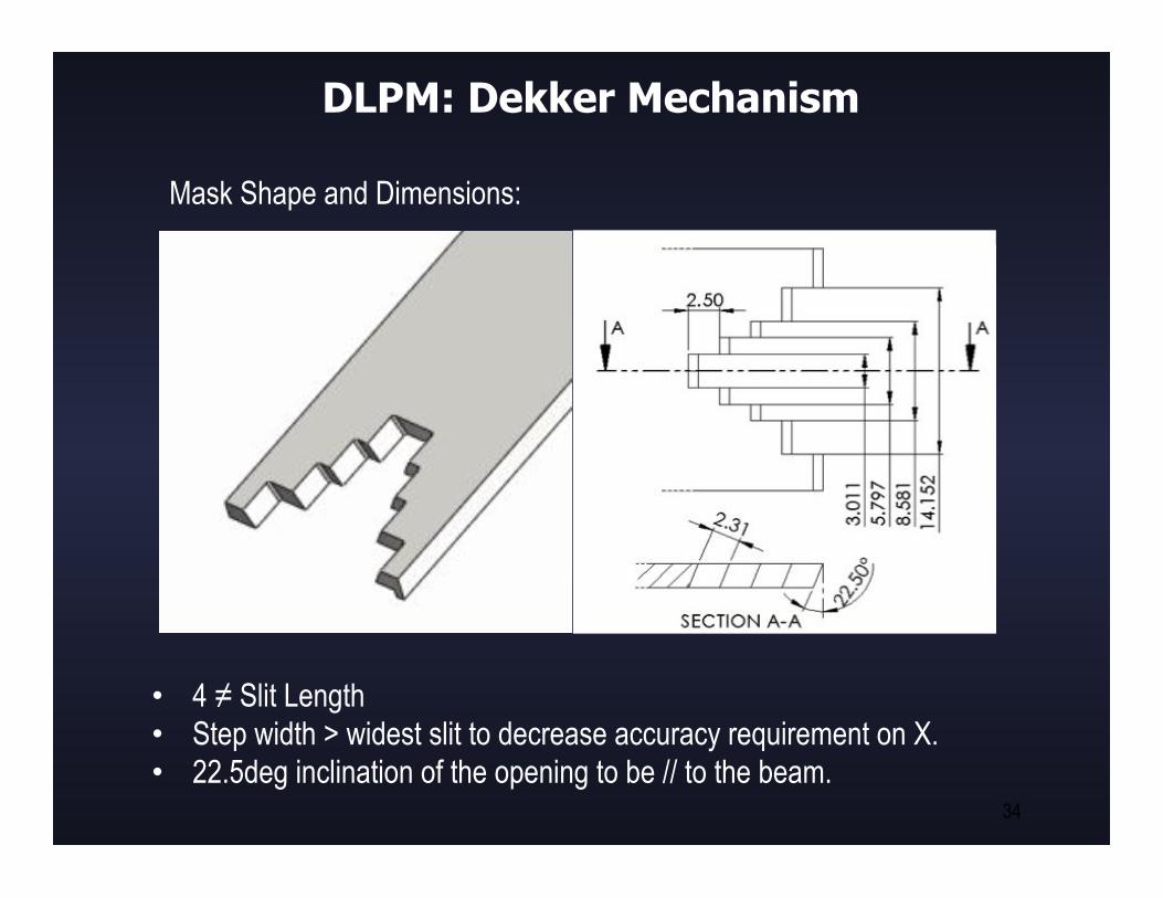
Mask Shape and Dimensions:
• 4 ≠ Slit Length • Step width > widest slit to decrease accuracy requirement on X. • 22.5deg inclination of the opening to be // to the beam.

DLPM: Dekker Mechanism
First Concept:
• Off-the-Shelf Piezo-Stage with Encoder (Cryogenic rated)
• Miniature Design • Light-tight enclosure of the
piezo-stage.
35 (dimensions in mm)

DLPM: Dekker Piezo-Stage Testing
• Refurbished an old instrument into a test dewar. • Test plan includes cryo& vacuum test, position hold test, re-initialization test,
hard-stop test and Lifecycles. • First and second tests unsuccessful. No movement at 77K. Still troubleshooting
with Vendor.
36
TEST SETUP

DLPM: Dekker Piezo-Stage Alternative Concept
• Flexure Stage designed using Flex-Pivots.
• Powered using a Stepper + Worm Gear + Eccentric Cam.
37
Cross-Section
Stepper
Worm Gear
(Flexure) (Eccentric)
Flex-Pivots

DLPM: Immersion Grating Mechanism
38
• Light-tight motor mount • Mounting Sub-plate • Preloaded Mirror Mount • 45deg stage due to
available Space

DLPM: Immersion Grating Mechanism
39

DLPM: Immersion Grating Mechanism
40

41
CONTINUOUS LINEAR POSITION MECHANISMS
(CLPM)

CLPM: Detector Mount and Stage
42

CLPM: Detector Mount and Stage
• Focus Stage Design based on SpeX Flexure-Stage but with simplified gearing (off-the-shelf planetary) and improved anti-backlash system.
• “Configuration Board” for ARC
controller cabling
43

CLPM: Detector Focus Stage
44
Anti-backlash System: • Split-Nut preloaded with wave-spring • Nuts shaped to stop relative rotation • Preload > Flexure Axial Force +
Moving Load

CLPM: Detector Mount and Stage
45
H2RG Mount with New Configuration Board: