preliminary engineering report tioga drain …€¦ · · 2015-12-03preliminary engineering...
TRANSCRIPT

42.¿o
¡\ø,{
PRELIMINARY ENGINEERING REPORT
TIOGA DRAIN
SWC PROJECT NO. I640
NORTH DAKOTA
STATE WATER COMMISSION
NOVEMBER 1978
I
I
Prepared By:
e ulJater Resources Engi neer
Submi.tted By:
TIOGA DRAIN
NORTH DAKOTA STATE I,/ATER COM¡4ISSIONSTATE OFF I CE BU I LD I NG900 EAST BoULEVARDBISMARCK, NORTH DAKOTA 58505
S!úC P roj ect # .l640
Dav dDi rector, Engineering D ¡vtst on
Approved By:
?
Vernon FahyState Engineer ü

rfl I z'E
-
rfl-r< (D
ctv .l oz
Þ> f+!+
J(o>
OO
or=
-r-tn
nÞfa
< A0r<
rtr+9
fll't
o<oo
l,trt
rt
zz,=
oo.(o
0,.i+
l$ ...O
J
lJt € 3 3 v
Þ @ r flt o Tt f) ô 2 { rn, 2 -l U'
-{ F o¡9€¡
3(!c
cU
¡ Êt
(.¡
(llJ{ -r. O
:-
-.uo
1foz
.r+
Àr!
o5 .lÀ o rlt
.frO ;o 'o :
o o.o I 3 ,ro Þ
".l o¡
'0r
.
t; tcr lo
( _{.=
{ rflcr
E=co
lrlrrô
z'rr-
lor
q3-
¡()rr
ô -r¡
ç,ct
:t
'uoo
-;''
3,rO ow (D -rm
.>1^
m = =v o z. =m -{ r an c v m
.o 'o frl z, (f x
.l' ,t rft z (t x TE'
r.¡t
\0C
'rvlr¡
N
PREL ¡MI NARY DES I GN FORTIOGA DRAIN
sl./c PRoJECT N0. 1640
I. INTRODUCTION
PURPOSE AND SCOPE
This report on the Tioga Drain watershed contains the results ofa prel iminary engineering design conducted by the State V/ater Commission
in cooperation v'/¡th the l.J¡ I ¡ ¡ams County Water Management D¡trict. The
objective of the preliminary design was to develop a b/ater management plan fora 15 square mile area west and north of Tioga. As part of the plan, ìt isintended to establ ish a legal drain to al leviate drainage problems. Since
there have been substantial expenditures to provide the city of Tioga withflood protection, this project is desîgned so as to prevent the creationof additional flood problems for the city of Tioga.
Preceding the engineering analysis is a general description of thewatershed and a discussion of the problem areas. The engineering analysisincludes a hydrologic investigation of the area and a presentation and
discussion of the various alternatives. Fol lowing each alternative isa breakdown of the various costs of the alternative. An environmental
survey and a summary complete the report.The engineering analysis uti I ¡zes the best practícal technology to
devise alternatives that sufficiently meet the needs of the drainagearea. The prel iminary design of the drain and control structures comply
with criteria established by the State t'later Commission. Data used in thisrePort was obtained by the State l.later Commission, Ì,/¡l I iams County l¡/ater
Management District, and local individuals.

DESCRIPT¡ON OF PLANNING AREA
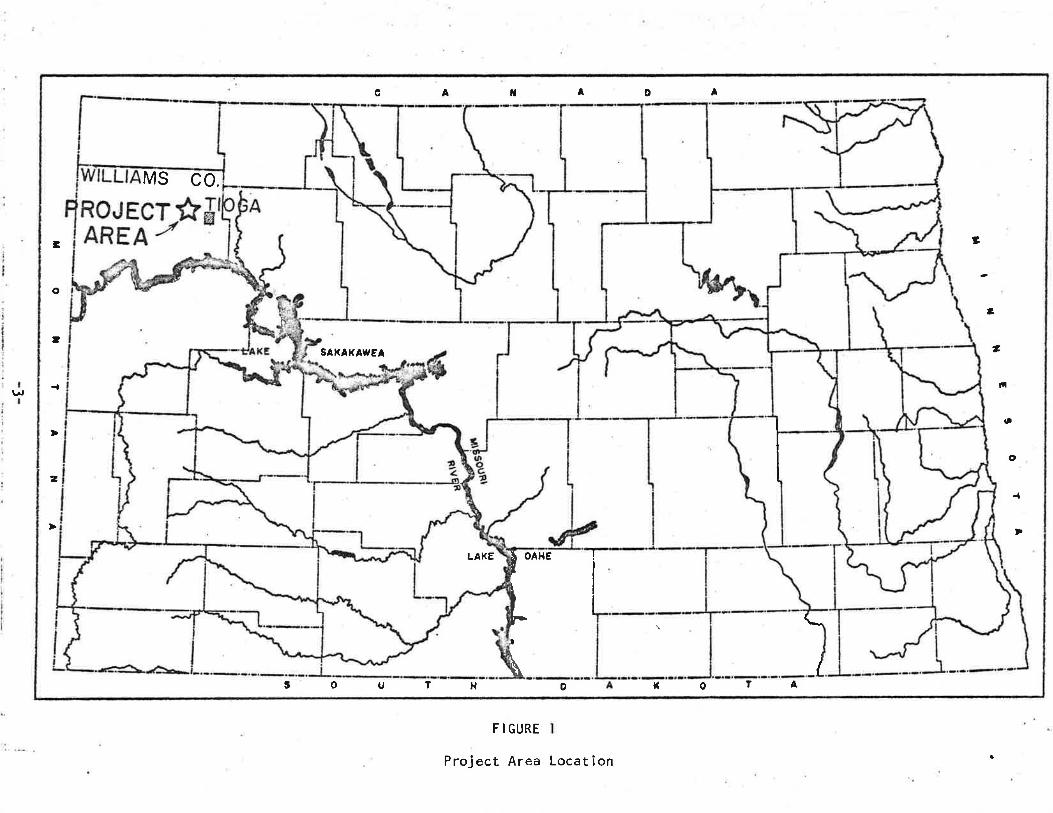
The project study area is located in t,Jilliams County. The drainage
area studied lies northwest and west of the city of Tioga (see Figure l).The drainage area contaÎns several major sloughs with no natural outletfor the sloughs except during periods of high water. During these
periods, the water contributes to flooding problems in Tioga. The area isprivately owned except for an area owned by the U. S. Físh and \,Jiìdl ifeService in the middle of the watershed.
The Tioga Drain watershed is located on the imaginary border
between the Missourî Plateau and the Missouri coteau in the Great
Plains physiographic province. Before the State bras glaciated, al I
draínage was directed generally northeastward toward Hudson Bay.
However, drainage patterns were drast¡cal ly affected by glaciation.The region of Missouri coteau is known for a characteristic of very
poorly developed drainage, which leaves numerous potholes, sloughs,
and lakes. 0n the other hand, the Missouri Plateau generally has
well developed drainage. ln the Tioga Drain watershed, an area ofpotholes and sloughs is found, necessitatíng improved drainage foropt¡m¡zation of agricultural land use.
The soils in the area are of the Coleharbor Formatîon, which includesal I the deposits of glacial origin. These deposits are mainly ti I l,outwash sand and gravel, and lake sediment. These were deposited duringseveral advances and retreats of glacîal ice.
The economy of the area is structured around agriculture. Most
of the land is productive farmland producing small grains and row crops.However, poor surface drainage hinders some farming operations in the area.The community which would be directly influenced by the development is Tioga.
-2-
c
U
A f{^
o A
3C
o
t
z
3
,li
o
o
-t
D
t o 1 1 AH f oD
MS co.
LAKE
SAXAKAf,'EA
a
il
It
OAHE
I
L
F I GURE
Project Area Locat i on
The closest major commercíal center is t¡Jil I iston, located approximately
30 miles west and 20 miles south from Tioga.
Precipitation for crop product¡on is'adequate during normal years,
although occasionally the reg¡oR suffers from períods of drought. The
average annuãl precipitation is l3* inches, most of which occurs during the
growing season. Approxìmately 80 percent of the precipitation occurs
during the months from ApriI through Septernber. The average annual
snowfall is 30 inches with 100 days during which there is one inch or
more of snow on the ground. The annual mean temperature is 39oF.
-4-
I I. STATEMENT OF PROBLEM
BACKGROUND
Flooding and drainage have been problems for the city of Tioga formany years. lt was brought to the State l,Jater Commissionrs attention inApril of 1975. At that time a slough to the west of Tioga (Biwer Slough)
was filled to capacity and was threatening to overtop dikes at the slough.
To remedy the situation a gated control structure and additiional dikes
ìr',ere instal led. This removed Tioga f rom eminent f looding danger f rom thisslough.
Another flooding problem was occurring at the same time Biwer Slough
was causing problems. Runoff from the Tioga Drain watershed was becoming
impounded at the section line between Sections 27 and 28 of Tioga Township
at the railroad-roadgrade crossing. The impounded water would then flowthrough two culverts, a 30" CMP and a 36'' cMP, and flood port¡ons of Tioga.
The flooding occurred as the runoff water drained through the city along a
natural drainage channel that also carried drainage from the city. The
capacity of the channel was exceeded, resul ting in flooding.A remedy suggested in July of 1975 was a floodway channel running south
from the railroad-roadgrade crossing, on the east side of the sectionline road for approximately l* miles. At thís point, the floodway channel
would discharge into a natural coulee. The cost of this floodway
lvas estimated at $30,000. Land acquisition became a major problem, so
the project was discontinued.
-5-

Following the dismîssal of the floodway, Webster, Foster and Weston
Consulting Engineers proposed a floodwater conduit inside the city of
Tioga. Their studies revealed that the flooding occurred when the water
impounded at the railroad-roadgrade crossing between Sections 27 and 28,
passed through a 30" culvert on the north side of the tracks and through
a 36,'culvert on the south side of the tracks. The brater would then flow
along the tracks until it reached Tioga. 0n the north side of the tracks,
Tioga has a 24" CMP culvert to receive the flows, which then pass through
Tioga. However, on the south side of the tracks, there was no culvert or
drain to receive the flows. These flows wouìd then back up, causing
flooding.
This are¿¡ on the south side of the tracks was where \,Jebster, Foster
and t'leston proposed to ¡nstall a 36" RCP floodwater conduit. Also to be
instal led were control gates on the 30t' CHP and 36" CMP at the impoundment
area. The cost of this project was estimated at $50,000 and was
completed by October of 1976.
CURRENT CONCERNS
ln March of 1976, a petition was received by the State llater Commission
from farmers north and west of Tioga to investigate the feas¡b¡l¡ty and
preliminary design of a legal drain (Appendix A). This petition asked forthe drainage of Simon Slough (Section 18, Tioga Township), Schm¡dt Slough
(Section 25, Golden Valley Township; Section 30, Tioga Township) and Mowdy
Slough (Section 19, Tioga Township)(See Figure Z). An agreemènt was signed in
April of 1976 between the State Water Commission and the W¡ll¡ams County
llater Management Boardrin regard to investigation and preliminary design of a drain.(Appendix B). A remittance of $1500 was received as the investigation fee.
-6-

36 36
sUB-BASIN 5r.96 SQ. Ml.
3l 3? 33 34
SUB- BASIN 95.4 SQ. Mt.
TIOGA30
¿29
SUB-BASIN 4l.02 SO. Mt.
26
23 24SUB-BASIN
0,36SQ. MI
l9o.36SO.MI
SUB-BASIN 2
SUB- BASIN1.3 S0. Mt.
20
SUB- BASIN
t.6 so. Mt.
/MOWDY/SLO!GHj5
2l ?2
6
l8 l6l4 l5
S/¡14ON
17
2SUB BASIN 7
so. Mr.
T. t57 N.
l5
9l2N 7
-\Â
SUB - BASIN 83.2 SQ. Mt.
I lo
2 I ã6 4 3
R.95W. TIOGA TWP.
. FIGURE 2Tioga Drain Sub-Basins
.-7-
GOLDEN VALLEY TWP R.96W.

LJork began on the prel iminary design and by May of 1977, the initialhydrology was completed. By June of 1977, a preliminary design and cost
estimate for the total drainage had been obtained. The proposal consisted ofa channel ranging in width from l2 feet to 40 feet with a slope of 0.0009
ft/ft The estímate also included three drop structures, two with a l2 footdrop and one with a five foot drop, and a couple 72t'x 44" CMP arch-culvertroad crossings. The cost for this project was estimated at $666,000, which
did not include any costs for relocation o¡ any facilities such as gas
I ines or land acquisition.In July of 1978, Gerald Rustad, Acting Secretary for the l'/ílliams
County l,Jater Management District, requested that the State I'later Commission
develop a new cost estimate on a modified plan for controlled drainage.
Controlled drainage makes use of maximum natural storage of water in the
area, but allows for drainage of the area with reduced discharges. The
reduction is realized from a lengthened duration of flows resulting from
the control structurers regulation of the flows. This report is the
result of the revision of the previous Tioga Drain project.
-8-

I I. ENGINEERING ANALYSIS
HYDROLOG I C INVESTI GATION
The purpose of the hydrologic investÍgation is to estimate the peak
flows ïn the Tioga Drain watershed for various frequency flows resulting
from snowmelt or rainfall. These peaks are then used to size the
drainage channel and structures. To obtain these peaks, the TR-20
computer program was utilized.The TR-20 computer program was developed by the Soi I Conservation
Service for their hydrologic analyses. This program requires various
parameters to generate runoff patterns from a watershed. A few of
the more important ones are given in the following paragraphs.
Cover complex numbers (CU) are used in estimatîng dÌrect runoff
from rainfall and snowmelt. To determine "CNil the soil type needs to be
determ¡ned using county soïl maps. There are four major soil groups forthe primary classification of soi ls. They are as fol lows:
Group A - Soils having high infiltrat¡on rates even whenthoroughìy wetted, consisting chiefly of deep, wel I to excessivelydrained sands and/or gravel. These soils have a high rate of watertransm¡ssion and would result in a low runoff potential.
Group B - Soils having moderate infîltrat¡on rates when thoroughlywetteãl-ãóEisting chief ly of moderately deep t'o deep, moderately wel Ito well drained soils with moderately coarse textures. These soilshave a moderate rate of water transmission.
Group C - Soils having slow infiltrat¡on rates when thoroughlyv,retted, consisting chief ly of (l) soiìs with a layer that impedesthe downward movement of water, or (2) soils with moderately fineto fine texture and a slow infiltration rate. These soils have aslow rate of water transmission.
Group D - Soils having very slow infiltration ratei whenthoroughly wetted, consisting chiefly of (l) clay soi ls with ahigh swelling potential, (Z) soils with a high permanent watertable, (¡) soils with claypan or clay layer near the surface,and (4) shaìloh, soils over nearly impervious materials. Thesesoils have a very slow rate of water transmission.
-9-

The soils are grouped v,,¡thout considering slope as a variable
and without considering the benefit of vegetative cover. The rrCNrsrr
are further adjusted for each drainage basin in the watershed by
determining the characteristics of the land use. The soil type
encountered in the analyses of Tioga Drain was type B. The land
use is given below:
LAND USE
85'4 Small grain cropPastureFa rmsteadsRoads
l00Z Total
Another parameter, is the time of concentrat¡on (tc), which denotes
the amount of time required for water to travel from the furthest end of a
drainage area to its outlet. The method commonìy used by the State Water
Commission is cal led the I'Upland Methodrr. Thïs method involves separating
the different flow conditions for each drainage area and determining the
length, drop and slope of the drainage area. Charts are used to obtain
the velocity for the various flow conditions using the slope of the area.
lJhen a velocity has been obtained, the time of concentrat¡on is determined
by dividing the length of flow reach by the velocity. The time of concentrat¡on
will determine the time of the peak flow from an area.
The amount of precipitation for a certain frequency rain or snow
storm is determined by using maps which show the precipitation amount in
inches for North Dakota. These maps are located in the North Dakota
Hydrology Manual developed by the Soil Conservation Service and the National
|Jeather Service. After the amount of precipitation is determined for the
storm frequencies to be analyzed, the amount of precipitation is adjusted
- l0-
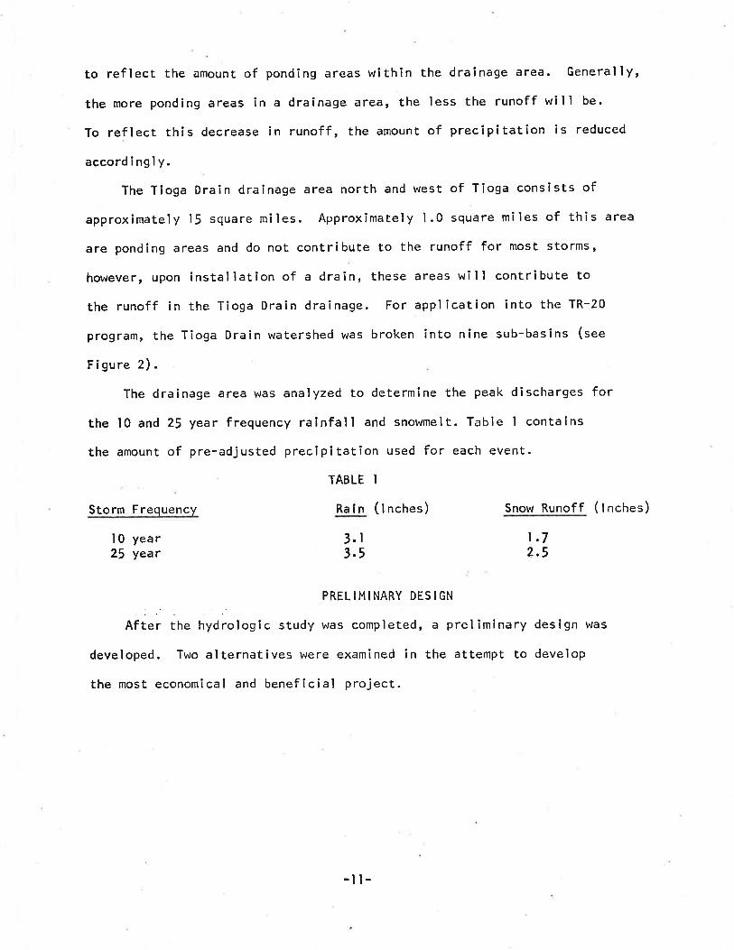
to reflect the amount of ponding areas within the drainage area. Generally,
the more ponding areas in a drainage area, the less the runoff wilì be.
To reflect this decrease in runoff, the amount of precipitation is reduced
accordingly.
The Tioga Drain drainage area north and west of Tioga consists of
approximately l! square miles. Approximately .l.0 square miles of this area
are ponding areas and do not contribute to the runoff for most storms'
however, upon installation of a drain, these areas will contribute to
the runoff in the Tioga Drain drainage. For application into the TR-20
program, the Tioga Drain watershed was broken into nine sub-basins (see
Figure 2).
The drainage area was analyzed to determine the peak discharges for
the l0 and 25 year frequency rainfall and snowmelt. Table I contains
the amount of pre-adjusted precipitatîon used for each event.
TABLE I
Storm Frequency Rain (l nches) Snow Runoff (lnches)
I 0 year25 year
PRELIMINARY DES¡GN
After the hydrologic study was completed, a preliminary design was
developed. Two alternatives were examined in the attempt to develop
the most economical and beneficial project.
t.72.5
3. r
3.5
-l t-
Alternative No. I
A main drainage channel was planned running west along the railroadtracks starting at the east edge of Section 28, Tioga Township until thechannel intersected the Section line between Sections 30 and 2!, also in theTioga Township. At this point, the proposed channel will run north alongthe Section lÎne road between Section 2j and Section 30 until the corner ofsections 19, 20,29 and 30 of Tioga Township. At this point, the channelsplits. One branch cont¡nues north along County Road #21 untíl ¡t reaches
Simon Slough in Section 17 of Tioga Township. The other branch will run
west from the Section corner in the ditch along County Road #10 until ¡treaches Schmidt Slough in Section 30 of Tîoga Township. A small lateralchannel will run south from Mowdy Slough in Section 28 of the Tioga Townshipto t¡e into the main drain.
For apPlication in the TR-20 computer program, the above drain systemwas divided ínto four major reaches. The reaches are Reach l, that portionof the draín running from Simon sìough south along county Road #Zl untiltlre section corner of sections lg, zo, 29 and 30; Reach 2, that port ionof the drain running from the section corner of sections 19, zo, zg and l0south untíl it meets the railroad tracks and then west along the railroadtracks until it runs into an area operated by the U. S. Fish and l,lildl ifeService in Section 28 of the Tioga Township; Reach 3, that portion of thedrain running f rom the U. S. Fish and t^ri ldl ife Game Management area eastunt¡l it meets the Section line road between Section 27 and 28 of theTioga Township; and Reach 4, that portion of the drain running fromschmidt slough east until the section corner of Sections 19, 20,29 and
30 of the Tioga Township (see Figure 3).
-12-

36 36 3l 3? 33 34
TIOGA3026
23 24II
l9
ACH I
20
t4 l3 l6 l5
ï
il a2R¡
9 lo
2
/
e 5 4 t
R.95 W. 'rloGA TWfì
FIGURE 3Channel Localion
_ t3_
GOLDEN VALLEY TWP R.96W.
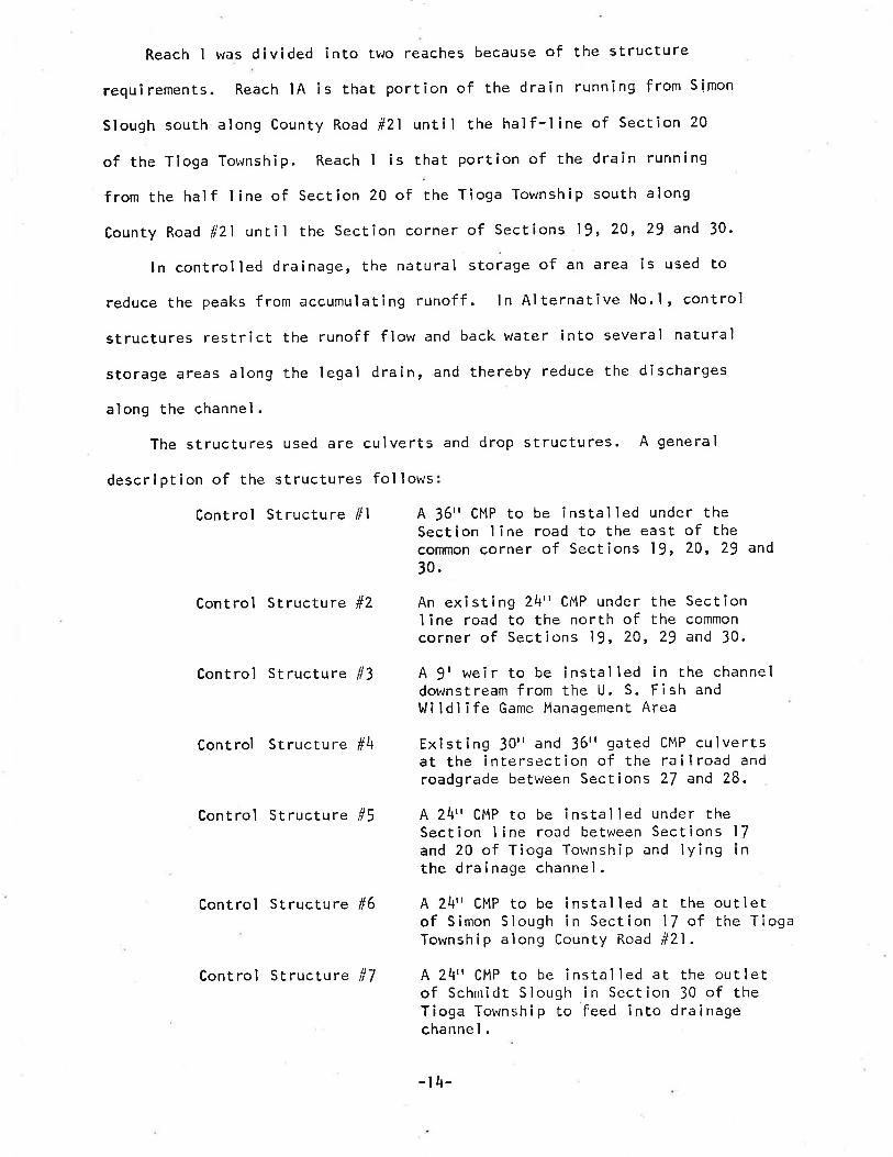
Reach I was divided into two reaches because of the structure
requ¡rements. Reach lA is that portion of the drain running from Simon
Slough south along County Road #21 until the half-l¡ne of Section 20
of the Tioga Township. Reach I is that Portion of the drain running
from the half line of Section 20 of the Tìoga Township south along
County Road #21 untiì the Section corner of Sections 19, 20,29 and 30.
ln controlìed drainage, the natural storage of an area is used to
reduce the peaks from accumulating runoff. ln Alternatíve No.l, control
structures restrict the runoff flow and back water into several natural
storage areas along the legal drain, and thereby reduce the discharges
along the channel.
The structures used are culverts and drop structures. A general
description of the structures fol lows
Control Structure #1 A 36" CMP to be installed under theSection line road to the east of thecommon corner of Sections 19, 20, 2! and30.
Control Structure #2 An existing 24" CMP under the SectionI ine road to the north of the commoncorner of Sections ì9, 20, 29 and 30.
Control Structure #3 A 9' weir to be installed in the channeldownstream from the U. S. Fish andt^r¡ ldl ife Game Management Area
Existing 30'r and 36'r gated CMP culvertsat the intersection of the railroad androadgrade between Sections 27 and 28.
Control Structure #\
Control Structure #5 A 24" CMP to be installed under theSection I ine road between Sections l7and 20 of Tioga Township and lying Înthe dra i nage channel .
Control Structure #6 A 24'r CMP to be installed at the outletof Simon Slough in Section 17 of the TiogaTownship along County Road #21.
A 24" CMP to be instal led at the out'letof Schmidt Slough in Section 30 of theTioga Township to feed into drainagechannel.
Control Structure #7
-t4-
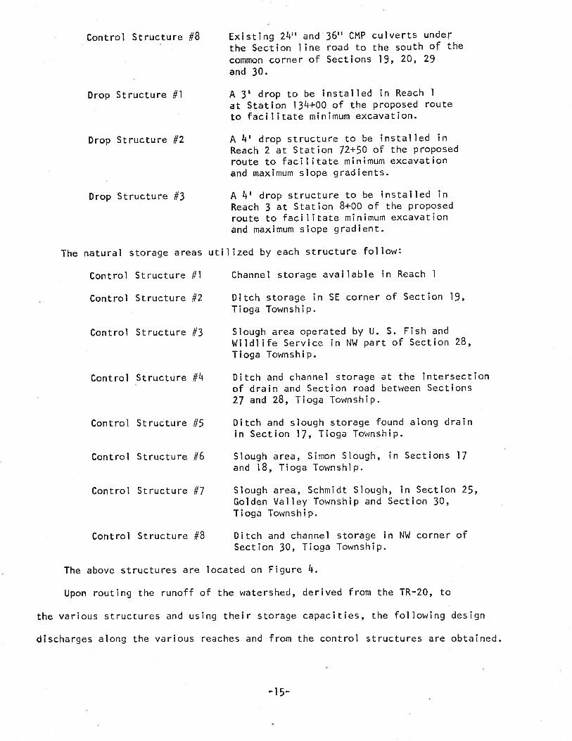
Control Structure #8
Drop Structure #l
Drop Structure #2
Drop Structure #3
The natural storage êreas
Control Structure #l
Control Structure #2
Control Structure #3
Existing 2\" and 36rr CMP culverts underthe Section I ine road to the south of thecommon corner of Sections l9' 20, 29and 30.
A 3t drop to be installed in Reach Iat Station 134+00 of the proposed routeto faci I itate minimum excavation.
A 4t drop structure to be installed inReach 2 at Station 72+50 of the proposedroute to faci I itate minimum excavationand maximum slope gradients.
A 4t drop structure to be ìnstalled inReach 3 at Station 8+00 of the proposedroute to faci I itate minimum excavat¡onand maximum slope gradient.
uti I ¡zed by each structure fol low:
Channel storage avai'lable in Reach I
Ditch storage in SE corner of Section 19,Tioga Township.
Slough area operated by U. S.I.t¡¡dlife Service in NW part ofTioga Township.
Fish andSection 28,
Control Structure #4 Ditch and channel storage at the intersectionof drain and Section road between Sections27 and 28, Fioga Township.
Control Structure #5 Ditch and sìough storage found along drainin Section 17, 1 ioga Township.
Control structure #6 Slough area, Simon Slough, in Sections 17and 18, Tioga Township.
Contr:ol Structure #7 Slough area, Schmidt Slough, in Section 25,Golden Valley Township and Section 30,Tioga Townshi p.
Control Structure #B Ditch and channel storage in NW corner ofSection 30, Tioga Township.
The above structures are located on Figure 4.
Upon routing the runoff of the watershed, derived from the TR-20, to
the various structures and using their storage capacities, the following design
discharges along the various reaches and from the control s.tructures are obtained.
-t5-

l-56 36 3l 32 33 34
7
'f toGA30 2926
SC RE
28RE
23 24
STRUCTURE
l9
STRUCTURE I
20 2t
e
z2
l4 l3 l8
STRUCTURE 6
STRUCTURE 5
17 l6 l5
tl 7l2FJ 9I lo
2 6 5 34
R.95 W. TIOGA TWP
FIGURE 4, St ructu re Locat i on- r6-
GOLDEN VALLEY TWP R.96w.

TABLE 2
ReachChannel DesignPeak Discharqe
53 cfs16 cfs70 cfs5l cfs55 cfs
IAI234
ControI StructureSt ructu re Des i gnl0 Year Discharge
24 cfsll cfs33 cfs50 cfs
Structure Des i gn25 Year Discharqe
I234567I
37 cfs17 cfs50 cfs70 cfs8 cfs5 cfs
l0 cfs50 cfs
6 cfs4 cfs8 cfs
36 cfs
The channel design discharges from Table 2 are the l0 year storm
peaks. These discharges are not """uruiative and are dependent upon controlìedreleases from upstream structures and local runoff (See Figures 3 and 4).These are the discharges required by the criteria set forth by the State
lrlater Commission, which requi re the 2J year storm peak discharge to design
structures and the l0 year storm peak discharge to design channels.
The design channel has a 12 foot bottom width and 4 to I side slopes.
The various reaches have different design discharges and therefore, have
different slopes, velocities, and flow depths. This is shown below:
Reach ìA Station 153+00 to Stat¡on 220+00slope = 0.0011 ftlftdeslgn discharge = 53 cfsvelocity = 1.63 ftlsec @ 1.72'
Station 134+00 to 153+00slope = 0.0011 ft/ftdesign discharge = l6 cfsvelocitY = l.13 ftlsec @ 0.89'
Stat ion I 34+003t drop structure_17-
dept h
dept h
Reach I

Station 128+00 to 134+00slope = 0.0O6 ftlftdes I gn d i s'e ha,r'ge . = I6 cf sveloclty = 2.00 ftlsec @ 0.55r depth
Reach 2
Reach 3
Reach 4
Station 72+59 to 120+00slope = 0.00125 fr.lftdesîgn discharge = 70 cfsvelocity = I.84 ftlsec @ 1,92' depth
Station 72+5A4r drop structur"e
S'tation 5,8+oo ts 78*50slope = 0.0045 ftlftdesign dîscharEe = /0 cfsvelocity = 2.91 fty'sec @ |,37r depth
Station 8+00 to 46+ooslope = 0.00425 ftlftdesign dlscharge = 5l cfsvelocity = 2.58 ftlsec @ l.l7r depth
Stat¡on B+00. 4r dro¡ structure
starion 6+00 o 8+00slope = 0..005 fr/ftdesign discharEe = $l cfsvelocitY = Z-73 ftlsee @ l-l2r depth
Statlon 0+00 ro 50+00slope = 0.0006 ft/ftdesïgn discharge * 55 cfs
- l8-
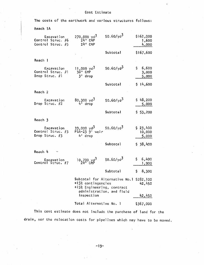
Cost Est imate
The costs of the earthwork and various structures follows:Reach lA
Excava t i onControl Struc. #6Control Struc. #5
Reach I
Excavat i onControl Struc. #lDrop Struc. #l
Reach 2
Excava t i onDrop Struc. #Z
Reach J
Excavat i onControl Struc. #3Drop Struc. #3
Reach 4
yd3 $0.60/yd3 $ 1 62 ,000l,6004,ooo
$ 1 67,600
$ 6,6003, 0005,000
$ 38,400
$ 8,300
$282 , I oot+2,450
\2rl+5o
0270,22
4'4'
00PCM
CMP
Subtota I
$0. 6olyd31,000 yd336" CMP3' drop
Subtota I
8o 30t ' to. 6o/vd3ovd
d rop
$ t4,600
$ 48,2005,000
Subtota I $ 53,200
ydg'
3 $0. 60lYd3 $wetr
Ir
39,PSA
000-23rd4 rop
23l05
00,\000000
- Excqvat¡on to,7oo vd3 $0.60/yd3Controì Struc. #7 24" CúP$ 6,400
I,900
Subtota I
Subtota I
Subtotal for Alternative No.l+15% contingencies+15% Ensineering, contract
admîn¡strât ion, and f ieldi nspect i on
Total Alternative No. I $367,000
This cost estimate does not include the purchase of land for the
drain' nor the relocation costs for pipelines which may have to be moved.
-r9-
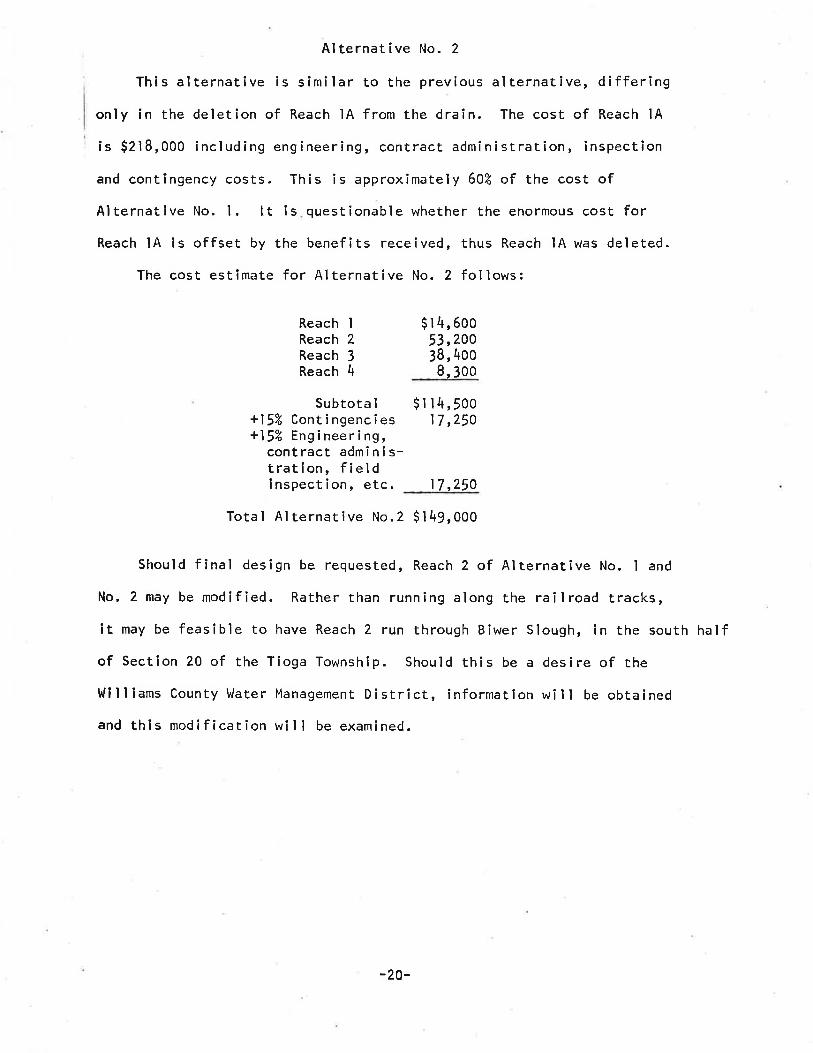
Alternative No. 2
This alternative is similar to the previous alternative, differingonly in the deletion of Reach lA from the draîn. The cost of Reach lA
is $2ì8,000 including engineering, contract administration, inspection
and contingency costs. This is approximately 60't of the cost ofAlternative No. l. tt is questionable whether the enormous cost forReach lA is offset by the benefits received, thus Reach lA was deleted.
The cost estimate for Alternative No. 2 follows:
$ t 4,60o53,20038, 4oo8, 3oo
Subtota I+15% Contingencies+15% Engineering,
contract adminis-trat¡on, fieldinspection, etc.
$ t t 4,5ool7 ,250
ReaReaReaRea
I234
chchchch
17,250
Total Al ternative No.2 Sl49,OOO
Should final design be requested, Reach 2 of Alternative No. I and
No. 2 may be modified. Rather than running along the railroad tracks,it may be feasible to have Reach 2 run through Biwer Slough, in the south halfof Sectíon 20 of the Tioga Township. Should th¡s be a desire of the
lt i I I ¡ams County llater Management District, ïnformation wil I be obtained
and thi s mod i fi cat ion wi I I be exami ned.
-20-

IV. ENVIRONMENTAL SURVEY
The following environmental survey will give an overview of the
positive and negative environmental impacts that would result from the
implementation of this project. This is not ìntended to be a comPrehensive
envi ronmental assessment, however, it wi I I identify subjects that would
be analyzed in detail in an environmental assessment. ln the following
paragraphs several environmental categories are identified and discussed
specifical ly for the Tioga Drain watershed.
LAND USE
The Tioga Drain watershed currently has the following land use
breakdown:
Smal I Grains
Pasture
lJetlands
Roads
Fa rmsteads
802
13"Á
5Z
tz
1%
I 002
The wetland areas not currently functioning as wi ldl ife management
areas would be converted to cropland as a result of this project. Some
land will be removed from agricultural production for the construction
of the drainage channels.
Aesthet i cs
The excavated drainage channels will not conform to the natural
environment. However, the excavated mêterial will be leveled and the
channel will be seeded with native grasses. The draining of the wetland
-21-

areas w¡thin the watershed wiìl eliminate the unsightly shallow bodies of
water that now exist.DOVINSTREAM FLOOD FLOV/S
The Tioga Drain watershed is located within the tJhite Earth River Basin.
As a result of this project there will be additional area contributing to
this basin. However, the peak discharge from the area will not be increased
because the discharge is controlled by the capacity of the Tioga city storm
sewer system. This project would result in an increase in the total volume
of runoff from the Tioga Drain watershed because of the increase in the
contributing area.
DO\,INSTREAM I¡,ATER QUAL I TY
Agricultural runoff, containing sediment and dissolved chemicals, is
presently stored in potholes and sloughs and does not normally contribute to
discharges from the watershed. This runoff would contribute ¡f this project
were constructed. However, the water qual ity of this additional discharge
wouìd be sîmilar to that of the remaÌnder of the \,lhite Earth River Basin.
FISH AND W¡LDLIFE
There is no existing water within the watershed that is suitable formaintaining a fish habitat, and the proposed project will not produce a
body of v,,ater that would support f ish life. No f ield data has been obtained
for wi ldl ife population wîthin the watershed. The implementation of the
proposed project will destroy some freshwater wetìands.
t RREVERS I BLE AND I RRETRI EVABLE COMM ITMENT OF RESOURCES
All materials, labor and energy used in the construction of the project
would be i rretrievable.
-22-

V. SUMMARY
The purpose of this report v,/as to present alternative plans for a
legal drain. This drain was to drain three major sloughs without creating
additional flood problems for the city of Tioga.
Two alternative designs for this drain were developed. Alternative
No. I drains the sloughs requested by the original petition and follows
the suggested route. The cost for this aìternative is estimated at
$367,000. Alternative No. 2 drains the same basin as Alternative No. I ,
with the exception of Simon Slough. The cost for this alternative isestimated at $149,000.
Because of the large expense incurred with the addition of draining
Simon Slough, the State llater Commission suggests that Alternative No. 2
be pursued further. The benefits received from the drainage of Simon
Slough may warrant the expense of incorporating this area into
the legal drain, however, at this time it is questionable.
Should a f inal design be requested by the l,li I I iams County Water
Hanagement District, addìtional information will be obtained to facilitatethe design. Also, input from the local population will be very helpful
in the final design.
-23-

APPEND I X A
Copy of 0riginal Petition
-2\-
:--(
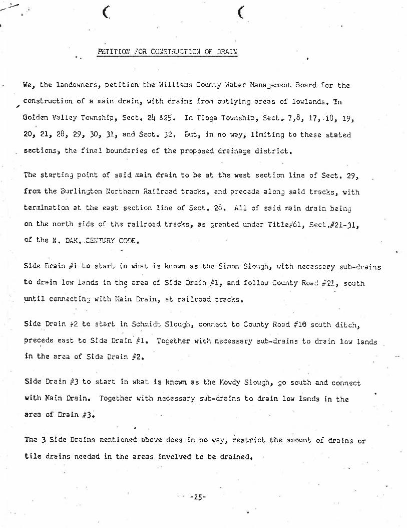
FETITION iOR CCì{STRUCTIOi{ CF D;ìAIN
l{e, t,he landov¡ners, p¿tibion the llillians CounLy I'iaber l4ana3enanL Board for theconstrucÈion of a main drain, r,rith drains fron o:ùlying areas of lowlands. InGolden Valley Tor"rrship, SecL. zlJ, &25. In Tioga To'"rnshir, SecL- 7r8, 17, .18, L9,
20,21,28r 29, 30, ll, and SecL. J2. BuL, in no r^ray, linrit.ing üo these sLated
. s?cLions, the final boundaries of the proposed drainage dìsLríct.
The sLarLin3 poinL of said nain drain to be aL the uesl section line of Sect. 29,
fron the tsurlinglon ìrlorLhern Railrcad tracks, and preczde alonE said tracks, uiLhterninaLion aL Lhe east section line or' Secb. 28. À11 of said nain drain baiag
oa t'h¿ north side of th¿ railroad tracl*s, as :ranted'¿nder TitIe;6L, SecL.ë2L-3L,of the N. DÂK..CEÌ'jT,JRY CODE.
Side Drain #1 to starL in',¡haL is kno'¿n as Lhe Sinon Slough, wiLh nec¿ssary sub-drairst,o drain low lands in the area of Side Drain #1r and follor.r Counfy RoeC rZ]-, soubh
unbil connecting wiùh r''iai.n Drain, aL railroad trackso
Slde Drai^;2 Lo siarL ín Sct'-::ridl Slough, connect to Counly Road #1ô soufh ditch,precede east Lo Sid¿ Drai'n *L. Togeùher r¡ith necessary sub-Crains Lo drain 1o.r land.s
in the ar¿a of Side Drain ¡#2.
Slde Drain #3 t,o starb in what is knor¡n as Èhe llowCy Slough, go sor:Lh and conneclrith llain Drain. TogeLher with necessary sub-drains fo drain low lands in ¿he
area of Drain #3.
The I Sida Drains nenLioned. obove d.oes in no rray, resLrict the ano,:nf or'drains orttle d¡alns needed ln the areas involved to be drained.
(
-25-
-92-
?z;1 .€?(
:è)
2,/iþ
'r l_,./
¿'-)
L
' t'./'(
?6
4
1t,l/
, ?,,
/t
It fslÞr/:.,ì ì'.,1ì') ì/)11f1 -r-
1,t..:1.1,.¡ 1,..,t,J.L
I
-t.'tì fI -¡. ì e\j,. '(. ¡!
a
a
a
a
a
I5
T
6
¿
T
'L- ) \-'- /.'l--'2I
vt¿'-ì:t!¡ v
/<'- t;: 'J,¿rv'z.a+ ¿-
¿ . a_I
I
iiI
i¡aa
rf,IfI
bs-a
gf¡¡
ll:
4å.a
¡
a?eossaJppíau¡eN
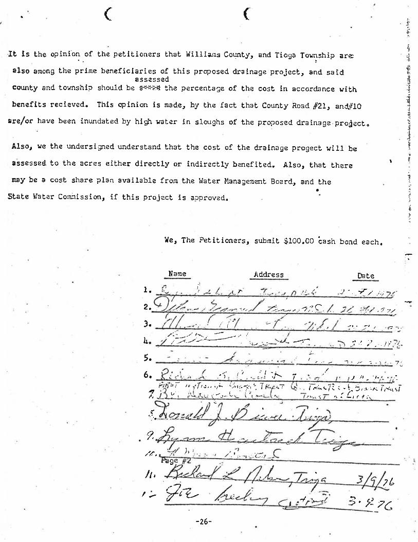
'i{3ea puog qsec OO.OOT$ ?Tlrgns rsJauol?T?ad a¡.¡ 3ap,
-. lpa^ordie sI ?sefoJd sTr{e ¡l ruo¡ss1ryoC Ja?el{ a?e?S
aq? pue (praog ?r:zuaeeuel{ Jalelq ar{? tuoJJ aTqeTle^e ue1d areqs ?soc e ag /tstraJaq? ?eq? fosTl .pa?IJau?q JtT?sarTpur Jo lî11ca:¡p Jar{?Ta sarDe aql o? passasse
aq rTIÄ ?3a6oJd a6eu¡erp aq? Jo ?sof, aq? ?eq? pue?srapun par6lsrapun aq? aÄ fosrv
c?3a6oJd a6eu¡e¡p pasocoJd aq? Jo sq6noTs uT Ja?eÄ q6¡q f,q pa?epunul uaaq a^eq Jo/aJ¿
OT#Þue .T¿# peou Á1rrno3 ?eq? ?oeJ aq? /îq rapeu sI uoluldo sTq¡ .pa^aToar s?IJauaqq?In a3ury-roc3e uI ?so3 aq? Jo eoeluac:ac a,{? F.r;l-*g aq pTnoqs clrlsltro? pue Á1tmoc
passess eples pue 31cafo.:d a6eulelp pasodoJd sTq? Jo saIJeIoIJauaq au¡TJd aq1 Euoure os¡e
-i a:e cilqsu¡{or e6ol¿ pue rÁ1rnro3 slrÊTTTIr4 ?eq? srauof?I?ad aq? Jo uo.¡u¡co aq? sI ?f
) )

APPEND I X B
Copy of 0riginal Agreement
-27-
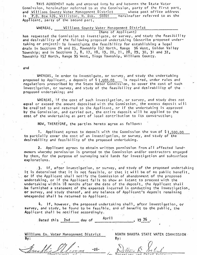
THIS AGREEMEIIT made ðnd entered into by and betvreen the St¿te lJaterCommìssion, hereinafter referred to as the Conrmission, pðrÈy of the first part,
d U¡lliams Count \,/ate r Han a ement D i st ri ctants P.0. Box 7 ,w too rr5 a here
u¡hose post of f i ce addressnafter referred to as Èhe
proposed by Applicant, aregulations prescri bed by
Appl icant, party of the second part,
}JHEREAs, !ri I I ¡ams Coun t Water I'lana ement DistrictNarne of App icant
has requested the Commission to investigate, or survey, and study the feasit,ilityand desirability of the follorving proposed undertakÌng (describe proposed under-taking or project): To investigate the feas¡b¡l¡ty for establishing a legaldrain in Sections 24 and 25, Torvnship 157 North, Range !6 lilest, Golden Val leyTownship; and in Sections /,8, 17,18, .l9,20, 2ì, 28,29, 30, 3l and 32,Township 157 North, Range !l West, Tioga Township, Wi I I ïams County.
and
tJHEREAS, in order to investigate, or survey, and study the underÈakingdepo s it of S I .soo.oo i s requi red, under rules and
to cover the cost of suchthe State Water Commission,investigation, or survey, and study of the feasibility and desirability of theproposed undertaking; and
UJHEREAS, if the cost of such investigation, or survey, and study does notequal or exceed the anount depos ited 'r¡i th the Commiss ion, the excess depos i t v¡i I Ibe credîted to and returned to the Applicant, or if the undertaking is approvedby the Commission, and carried out, the entire depos¡t w¡ll be applied to thecost of the undertaking as part of local contribution to its construction;
NOl,r, THEREFORE, the part¡es hereto agree as fol lows:
l. Applicant agrees to deposit with the Commissionto partial ly cover the cost of an investi gation, or survey,desirabîlity and feasibility of the proposed underLaking.
the sum of $ l.5OO.OOand s tudy of the
2. Applícant agrees to obtain written permissÌon from all affected ìand-owners wher;eby permission is granted to the Commission and/or contractors engagedby them, for the purpose of surveying said lands for investigatîon and subsurfaceexplorations
3. lf, after învestigation, or survey., and study of the proposed undertaking¡t is determined that ¡t is not feasible, or that it will be of no public benefit,or if the Applicant shaìl notify the Commission of abandonment of the proposedundertaking, or îf the Applicant fails to show an íntent to proceed with theundertaking within l8 npnths after the date of the deposít, the Applicant shallbe furnished a staËement of the expenses incurred in conducting the investigation,or survey, and study thereof, and any balance of Applicantrs deposit remaïningunexpended shall be returned to Applicant.
4. lf, however, the proposed undertaking shall, aftersurvey, and study, be found to be feaslble, and of benefit toAppl icant shal I be notified accordingly.
Dated this 2nd day of April t9 76
l,lill ¡ams Co. t¡Iater Management District
i nvest i gat îon, orthe publ i c, the
NORTH DAKOTA STATE WATER COI.IH ISS IONBy:
4
^^ -^l -r., -^¡l
8y:
-28- Í..-l'