preliminary geotechnical investigation report - 140
TRANSCRIPT
CAMBIUM INC.
866.217.7900
cambium-inc.com
Peterborough |Barrie | Oshawa | Kingston
Preliminary
Geotechnical
Investigation Report -
140 Lockhart Road,
Barrie
2021-02-02
Prepared for:
2640085 Ontario Inc.
© Cambium 2020 Reference No.: 10957-002
Preliminary Geotechnical Investigation Report - 140 Lockhart Road, Barrie
2640085 Ontario Inc.
Ref. No.: 10957-002
2021-02-02
Cambium Inc. Page i
Table of Contents
1.0 Introduction .......................................................................................................1
2.0 Investigation Methodology ..............................................................................2
2.1 Field Work ................................................................................................................... 2
2.2 Physical Laboratory Testing ........................................................................................ 3
3.0 Subsurface Conditions ....................................................................................4
3.1 Stratigraphy ................................................................................................................. 4
3.1.1 Topsoil ......................................................................................................................... 4
3.1.2 Earth Fill ...................................................................................................................... 4
3.1.3 Sand/Silty Sand ........................................................................................................... 4
3.1.4 Clayey Silt ................................................................................................................... 5
3.1.5 Glacial Till .................................................................................................................... 5
3.2 Groundwater ................................................................................................................ 6
4.0 Preliminary Geotechnical Recommendations ...............................................8
4.1 Excavations ................................................................................................................. 8
4.2 Groundwater Control ................................................................................................... 9
4.3 Earth Pressure Design Parameters ............................................................................. 9
4.4 Preliminary Foundation Design ................................................................................. 11
4.5 Frost Penetration of Foundations .............................................................................. 12
4.6 Earthquake Design Parameters ................................................................................ 12
4.7 Foundation Wall Backfill ............................................................................................ 14
4.8 Slab on Grade Design Parameters ............................................................................ 14
4.9 Perimeter Drainage ................................................................................................... 15
4.10 Site Servicing ............................................................................................................ 15
4.10.1 Excavation ................................................................................................................. 15
4.10.2 Bedding ..................................................................................................................... 15
4.10.3 Trench Backfill ........................................................................................................... 16
4.11 Pavement Design Consideration ............................................................................... 16
Preliminary Geotechnical Investigation Report - 140 Lockhart Road, Barrie
2640085 Ontario Inc.
Ref. No.: 10957-002
2021-02-02
Cambium Inc. Page ii
4.11.1 Subgrade Preparation ............................................................................................... 16
4.11.2 Typical Flexible Pavement Structure ......................................................................... 17
5.0 Limitations ..................................................................................................... 19
5.1 Design Review and Inspections ................................................................................ 19
5.2 Changes in Site and Project Scope ........................................................................... 19
6.0 Closing ........................................................................................................... 20
List of Appended Figures
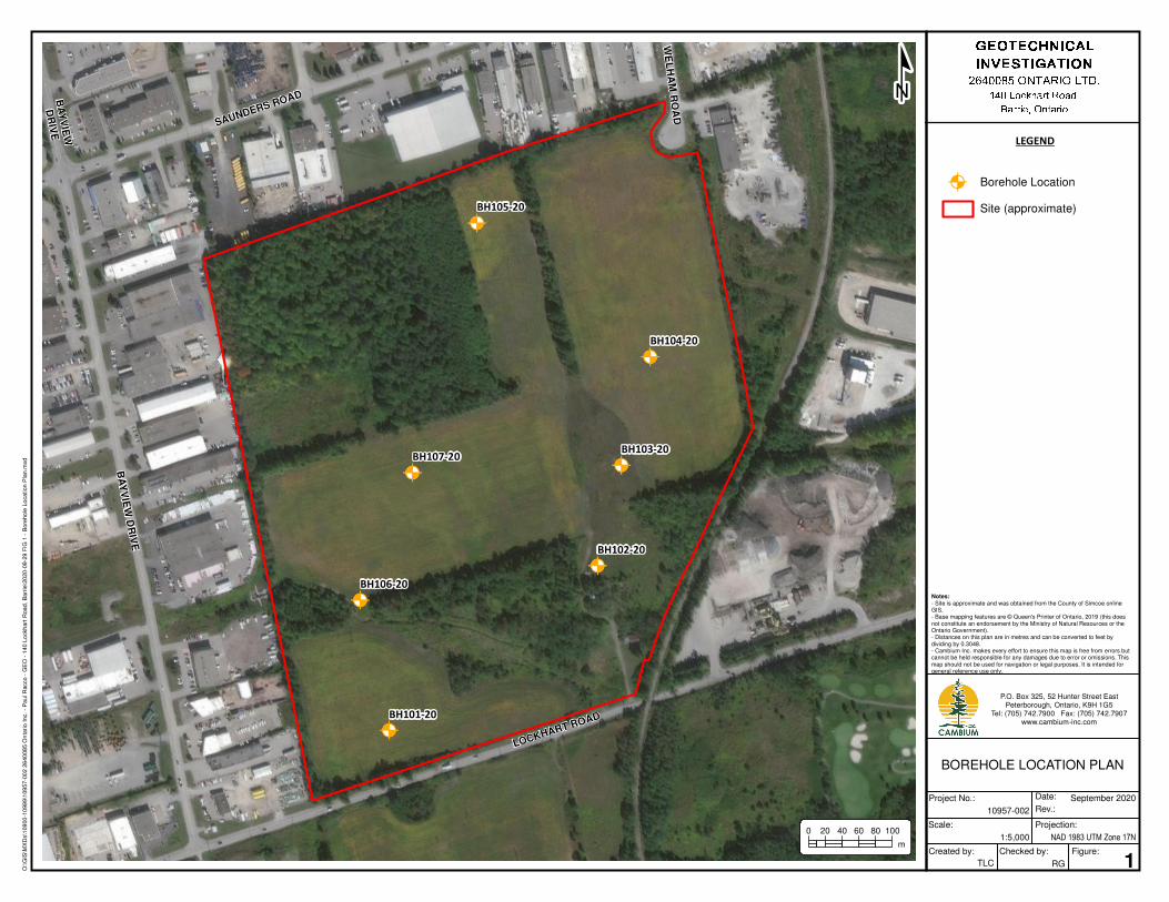
Figure 1 Borehole Location Plan
List of Inserted Tables
Table 1 Particle Size Distribution Results .......................................................................... 6
Table 2 Groundwater Observations ................................................................................... 7
Table 3 Earth Pressure Design Values ............................................................................ 10
Table 4 Acceleration Based Seismic Coefficients ............................................................ 13
Table 5 Velocity Based Seismic Coefficients ................................................................... 13
Table 6 Recommended Minimum Pavement Structure ................................................... 17
List of Appendices
Appendix A Borehole Logs
Appendix B Physical Lab Results
Preliminary Geotechnical Investigation Report - 140 Lockhart Road, Barrie
2640085 Ontario Inc.
Ref. No.: 10957-002
2021-02-02
Cambium Inc. Page 1
1.0 Introduction
Cambium Inc. (Cambium) was retained by Innovative Planning Solutions, representing 2640085
Ontario Inc. (the Client) to complete a preliminary geotechnical investigation in support of the
design and construction of the proposed industrial subdivision development located at 140
Lockhart Road in Barrie, Ontario. The Site is bounded to the east, north, and west by industrial
developments and to the south by Lockhart Road. A Site Plan, including borehole locations, is
included as Figure 1 of this report.
Preliminary site plans indicate that the proposed development is to include approximately 38 lots
zoned for light industrial, industrial use, stormwater management pond, environmental protection
and internal roadways.
This report presents the methodology and findings of a preliminary geotechnical investigation of
the subject site to determine the subsurface soil and groundwater conditions and provide
preliminary design recommendations. Based on the results of this investigation, the report
provides preliminary geotechnical engineering recommendations pertaining to the proposed
development. It is assumed that all the proposed lots will be developed with slab on grade single
storey structures and municipally serviced. A detailed geotechnical investigation, including
additional boreholes across the site is required once the details of the individual structures are
known.

Preliminary Geotechnical Investigation Report - 140 Lockhart Road, Barrie
2640085 Ontario Inc.
Ref. No.: 10957-002
2021-02-02
Cambium Inc. Page 2
2.0 Investigation Methodology
2.1 Field Work
The field investigation involved advancing a total of seven boreholes (numbered BH101-20
through BH107-20) across the site from September 3rd to 4th, 2020. The boreholes were
advanced from grade to depths ranging from 2.6 to 8.0 meters below ground surface (mbgs).
The location of the boreholes relative to existing site conditions are provided on the attached
Figure 1.
Drilling and sampling was completed using a track-mounted drill rig operating under the
supervision of a Cambium geotechnical analyst. The boreholes were advanced to the sampling
depths by means of continuous flight solid stem augers and 50 mm O.D. split spoon samplers.
Standard Penetration Test (SPT) results (N-values) were recorded for the sampled intervals as
the number of blows required to drive a split spoon sampler 305 mm in to the soil, using a 63.5 kg
drop hammer falling 750 mm, as per ASTM D1586 procedures. The SPT N-values are used in
this report to assess consistency of cohesive soils and relative density of non-cohesive soils.
Borehole and monitoring well samples were inspected and logged in the field using visual and
tactile methods. Soil samples were placed in labelled plastic containers for transport, review,
potential laboratory testing, and temporary storage. Open boreholes were checked for
groundwater and stability prior to backfilling and were backfilled in accordance with O.Reg. 903,
as amended. One groundwater monitoring well was installed in Borehole BH106-20 to measure
stabilized groundwater readings.
GPS coordinates of each borehole were obtained using a handheld GPS device. Boreholes
were survey using real-time kinematic (RTK) surveying equipment systems, the boreholes are
referenced based on geodetic elevations UTM zone 17T.
Records of the individual Borehole Logs are provided in Appendix A.
Preliminary Geotechnical Investigation Report - 140 Lockhart Road, Barrie
2640085 Ontario Inc.
Ref. No.: 10957-002
2021-02-02
Cambium Inc. Page 3
2.2 Physical Laboratory Testing
Physical laboratory testing was completed on select soil samples to confirm textural
classification and to assess geotechnical parameters. The results are summarized in the
respective soil stratigraphy sections in Section 3.0 and included in detail in Appendix B.
Preliminary Geotechnical Investigation Report - 140 Lockhart Road, Barrie
2640085 Ontario Inc.
Ref. No.: 10957-002
2021-02-02
Cambium Inc. Page 4
3.0 Subsurface Conditions
The subsurface soil and groundwater conditions encountered in the boreholes are presented on
the attached Borehole Logs in Appendix A. The stratigraphic boundaries indicated on the logs
are inferred from non-continuous samples and observations of drilling resistance and typically
represent a transition from one soil type to another, sometime gradually. The boundaries should
not be interpreted to represent exact planes of geologic change. The subsurface conditions have
been confirmed in a series of widely spaced boreholes, and will vary between and beyond the
borehole locations.
3.1 Stratigraphy
The following stratigraphy is based on the borehole findings, as well as the geotechnical
laboratory testing conducted on representative soil samples.
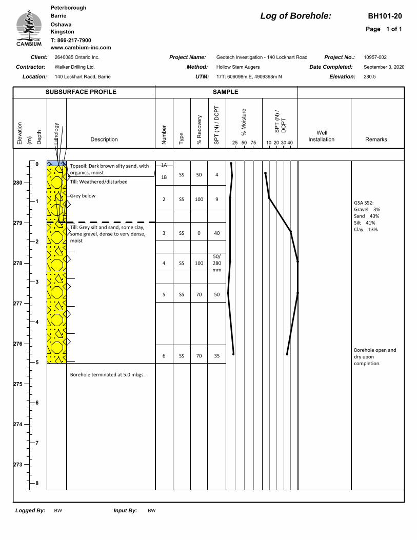
3.1.1 Topsoil
Topsoil was encountered from the surface at all borehole locations. The topsoil ranges in
thickness from 0.1 to 1.1 m. Assessments of organic matter content or other topsoil quality tests
were beyond the scope of this study. Proper delineation of the average topsoil thickness at the
site would require many additional test holes on a grid pattern.
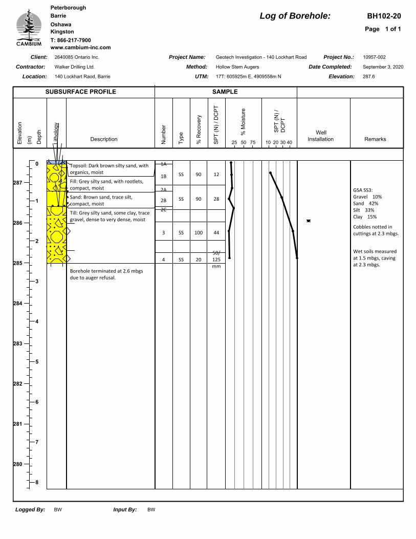
3.1.2 Earth Fill
A layer of fill material was encountered underlying the topsoil in BH102-20. The earth fill was
composed of grey silty sand, with rootlets, and extended to a depth of 0.8 mbgs and was
approximately 0.7 m thick.
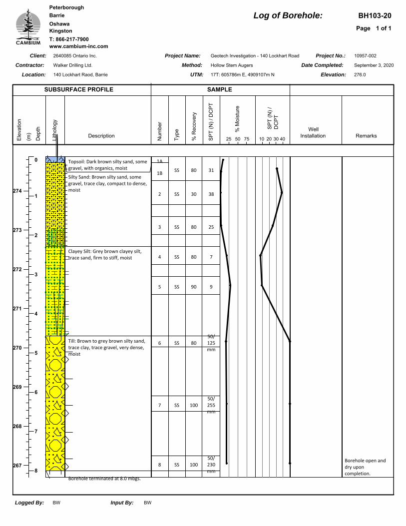
3.1.3 Sand/Silty Sand
Native deposits of sand and silty sand were encountered underlying the fill material in BH102-
20 and underlying the topsoil in BH103-20 and BH106-20. The sand deposit in BH102-20 is
composed of a brown sand, trace silt. The silty sand deposit encountered in BH103-20 and
Preliminary Geotechnical Investigation Report - 140 Lockhart Road, Barrie
2640085 Ontario Inc.
Ref. No.: 10957-002
2021-02-02
Cambium Inc. Page 5
BH106-20 is composed of brown silty sand, with trace clay and trace gravel encountered in
BH103-20.
The sand deposits were encountered at depths ranging from 0.8 to 1.1 mbgs and extend to
depths ranging from 1.1 to 2.3 mbgs. The measured thicknesses of the deposits range from 0.4
to 2.1 m.
SPT N-values measured in the sand deposits range from 25 to 38 blows per 305 mm of
penetration, reflective of a compact to dense relative density.
3.1.4 Clayey Silt
A native deposit of cohesive clayey silt was encountered underlying the silty sand in BH103-20
and BH106-20. The deposits are composed of grey or grey brown clayey silt with trace sand.
The clayey silt deposit was encountered at depths ranging between 1.9 and 2.3 mbgs and
extended to depths between 3.0 and 4.6 mbgs. The thickness of the deposit measured 2.3 and
1.1 m at BH103-20 and BH106-20, respectively.
SPT N-values measured in the clayey silt deposits range from 7 to 15, indicative of a firm to very
stiff consistency.
3.1.5 Glacial Till
Glacial till was encountered at all borehole locations underlying the clayey silty and/or topsoil
and/or sand deposits at all borehole locations. Glacial till is typically a heterogeneous mixture of
all grain sizes. At this site the glacial till is predominantly composed of grey or grey brown silty
sand to silt and sand with trace clay and trace gravel. Based on drilling observations there is
likely the presence cobbles and boulders within the glacial till, typically found in glacial till
deposits.
The glacial till was encountered at depths ranging from 0.1 to 4.5 mbgs. It should be noted that
the upper portions of the glacial till in BH101-20, BH104-20, BH105-20, and BH107-20 have
been disturbed. Where observed, the disturbed material extends to an approximate depth of 1.5
mbgs. All boreholes were terminated within the glacial till deposit at variable depths ranging from
Preliminary Geotechnical Investigation Report - 140 Lockhart Road, Barrie
2640085 Ontario Inc.
Ref. No.: 10957-002
2021-02-02
Cambium Inc. Page 6
2.6 to 8.0 mbgs. It should be noted that BH102-20, BH104-20, and BH105-20 terminated due
to auger refusal at depths ranging from 2.6 to 4.6 mbgs. Auger refusal can sometimes be
encountered on cobbles and boulders within the glacial till.
SPT N-values measured within the glacial till range from 11 to over 50, reflective of a compact
to very dense relative density.
Grain size analysis was completed on five (5) samples of the glacial till and the results are
summarized in Table 1. Detailed results are provided in Appendix B.
Table 1 Particle Size Distribution Results
Borehole Depth (m) Soil % Gravel % Sand % Silt % Clay
BH101-20 SS2 0.6 to 1.2 Sand and Silt 3 43 41 13
BH102-20 SS3 1.5 to 2.0 Silty Sand 10 42 33 15
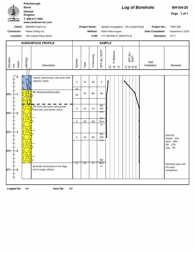
BH104-20 SS5 3.0 to 3.5 Silty Sand 15 49 27 9
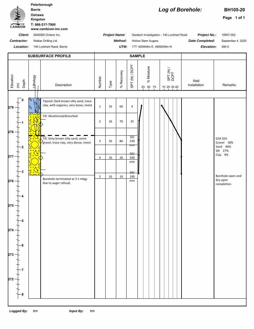
BH105-20 SS3 1.5 to 2.0 Silty Sand 18 46 27 9
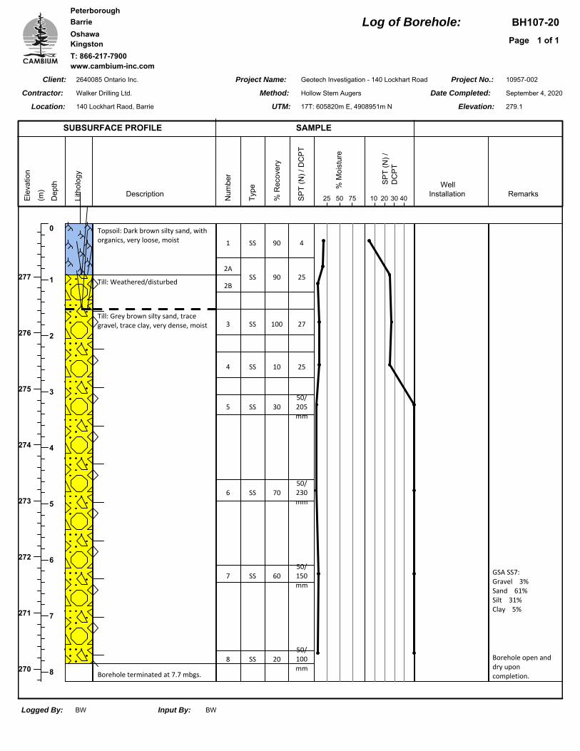
BH107-20 SS7 6.1 to 6.6 Silty Sand 3 61 31 5
3.2 Groundwater
The depth of groundwater was measured in each borehole immediately following drilling field
work. One (1) groundwater monitoring well was installed in BH106-20 in order to measure
stabilized groundwater conditions. The groundwater and caving (sloughing) observations are
shown on the respective Borehole Logs and summarized in Table 2.
Preliminary Geotechnical Investigation Report - 140 Lockhart Road, Barrie
2640085 Ontario Inc.
Ref. No.: 10957-002
2021-02-02
Cambium Inc. Page 7
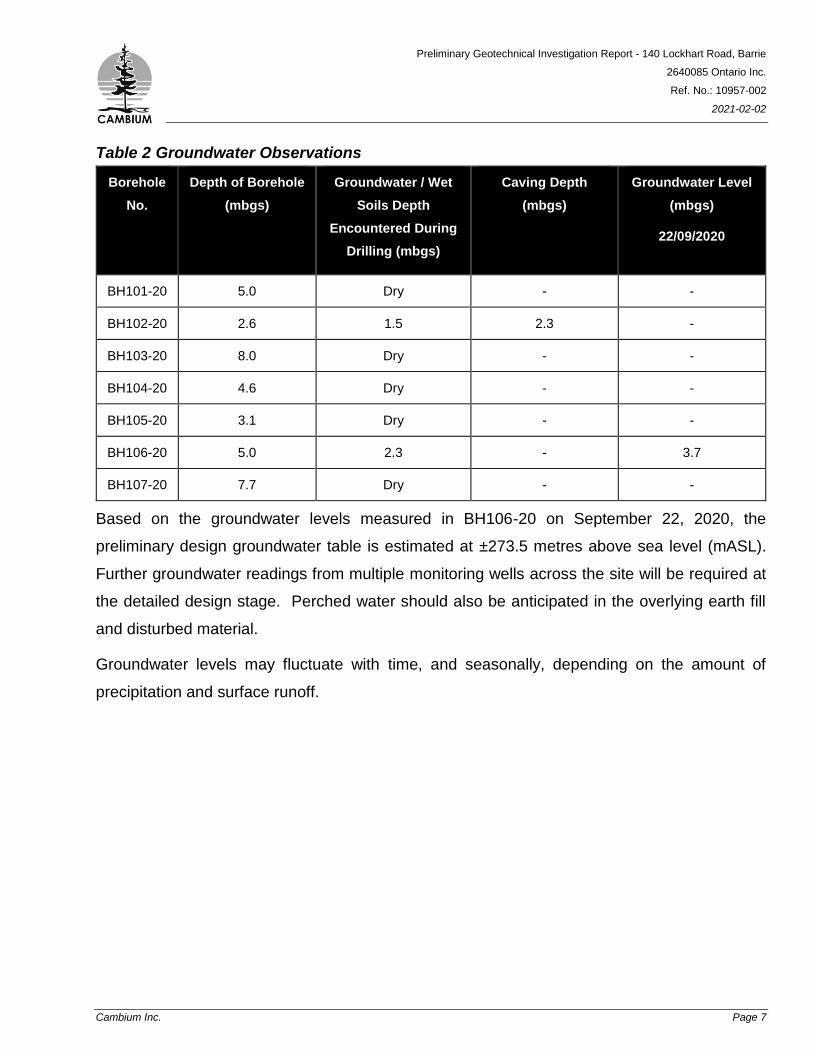
Table 2 Groundwater Observations
Borehole
No.
Depth of Borehole
(mbgs)
Groundwater / Wet
Soils Depth
Encountered During
Drilling (mbgs)
Caving Depth
(mbgs)
Groundwater Level
(mbgs)
22/09/2020
BH101-20 5.0 Dry - -
BH102-20 2.6 1.5 2.3 -
BH103-20 8.0 Dry - -
BH104-20 4.6 Dry - -
BH105-20 3.1 Dry - -
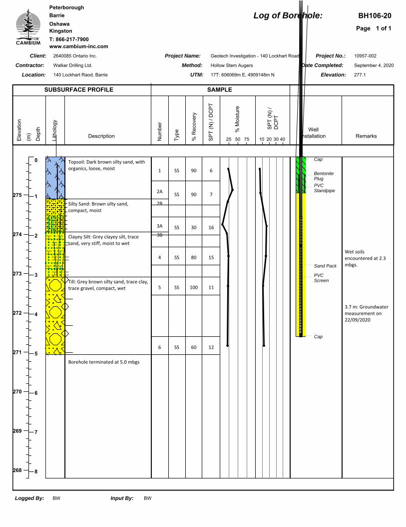
BH106-20 5.0 2.3 - 3.7
BH107-20 7.7 Dry - -
Based on the groundwater levels measured in BH106-20 on September 22, 2020, the
preliminary design groundwater table is estimated at ±273.5 metres above sea level (mASL).
Further groundwater readings from multiple monitoring wells across the site will be required at
the detailed design stage. Perched water should also be anticipated in the overlying earth fill
and disturbed material.
Groundwater levels may fluctuate with time, and seasonally, depending on the amount of
precipitation and surface runoff.
Preliminary Geotechnical Investigation Report - 140 Lockhart Road, Barrie
2640085 Ontario Inc.
Ref. No.: 10957-002
2021-02-02
Cambium Inc. Page 8
4.0 Preliminary Geotechnical Recommendations
The following preliminary discussion and recommendations are based on the factual data
obtained from this investigation and are intended for use by the owner and the design engineer.
Contractors bidding or providing services on this project should review the factual data and
determine their own conclusions regarding the construction methods and scheduling.
This report is based on the assumption that the design features relevant to the geotechnical
analysis will be completed in accordance with applicable codes, standards, and guidelines of
practice. If there are changes to the site development features, or there is any significant
variations in the subsurface conditions that are found before or during construction, Cambium
should be retained to review the implications of these changes with respect to the contents of
this report.
It is assumed that all the proposed lots will be developed with slab on grade single storey
structures and municipally serviced. A detailed geotechnical investigation, including additional
boreholes across the site is required once more design details are provided.
Based on site observations the existing elevations of the surrounding roadways and boreholes,
significant grade raise is not anticipated at this site. Site grading recommendations can be
provided depending on need and upon request.
4.1 Excavations
Temporary excavations must be carried out in accordance with the latest edition of the
Occupational Health and Safety Act (OHSA), Ontario Regulation 213/91 (as amended). For
practical purposes, the overburden soils at the site above the water table can be considered to
be Type 3 soils, as such excavation side slopes should be no steeper than 1H:1V. Below the
water table soils at the site would be considered as Type 4 soils and would require side slopes
of no steeper than 3H:1V. Minimum support system requirements (shoring) for steeper
excavations are stipulated in Sections 235 through 238 of the Occupational Health and Safety
Act (OHSA), Construction Projects, Part III.
Preliminary Geotechnical Investigation Report - 140 Lockhart Road, Barrie
2640085 Ontario Inc.
Ref. No.: 10957-002
2021-02-02
Cambium Inc. Page 9
Excavation side slopes should be protected from exposure to precipitation and associated
ground surface runoff and should be inspected regularly for signs of instability. If localized
instability is noted during excavation or if wet conditions are encountered, the side slopes should
be flattened as required to maintain safe working conditions or the excavation sidewalls must be
fully supported (shored).
Larger size particles, such as cobbles and boulders) will be encountered within the glacial till
deposit. The size and distribution of such obstructions cannot be predicted with boreholes, as
the sampler size in insufficient to secure representative particles of this size. Provisions should
be made in excavation contracts to allocate risks associated with the time spent and the
equipment utilized to remove or penetration such obstructions, when encountered.
4.2 Groundwater Control
No groundwater was observed in the boreholes immediately following drilling field work in
September, 2020. Stabilized groundwater levels measured in the BH106-20 monitoring well in
September, 2020 indicate a groundwater level at a depth of 3.7 mbgs (±273.5 mASL). Perched
water should also be anticipated within the subsurface deposits, such as fill, sand, and disturbed
glacial till.
Further hydrogeological data will be required in order to provide accurate groundwater control
measures and determine Ministry of the Environment, Conservation, and Parks (MECP)
requirements.
Agricultural drainage pipes may be encountered during the excavation of the proposed
structures. Any drainage pipes could be a source of significant volumes of water, which could
impact construction work and subgrades. It is recommended that any drainage pipe encountered
during the excavation be removed a horizontal distance of 2 m from the edge of the excavation
and appropriately sealed.
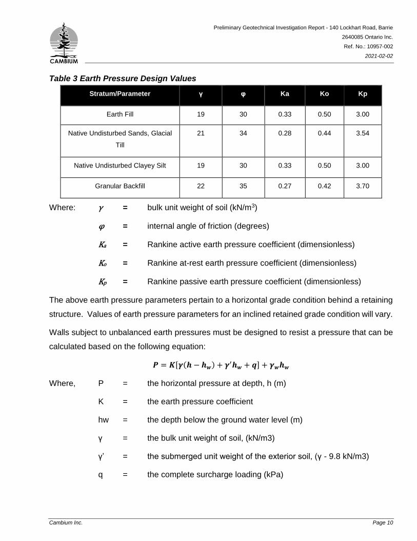
4.3 Earth Pressure Design Parameters
The appropriate values for use in the design of structures subject to unbalanced earth pressures
at this site are tabulated as follows in Table 3:
Preliminary Geotechnical Investigation Report - 140 Lockhart Road, Barrie
2640085 Ontario Inc.
Ref. No.: 10957-002
2021-02-02
Cambium Inc. Page 10
Table 3 Earth Pressure Design Values
Stratum/Parameter γ φ Ka Ko Kp
Earth Fill 19 30 0.33 0.50 3.00
Native Undisturbed Sands, Glacial
Till
21 34 0.28 0.44 3.54
Native Undisturbed Clayey Silt 19 30 0.33 0.50 3.00
Granular Backfill 22 35 0.27 0.42 3.70
Where: γ = bulk unit weight of soil (kN/m3)
φ = internal angle of friction (degrees)
Ka = Rankine active earth pressure coefficient (dimensionless)
Ko = Rankine at-rest earth pressure coefficient (dimensionless)
Kp = Rankine passive earth pressure coefficient (dimensionless)
The above earth pressure parameters pertain to a horizontal grade condition behind a retaining
structure. Values of earth pressure parameters for an inclined retained grade condition will vary.
Walls subject to unbalanced earth pressures must be designed to resist a pressure that can be
calculated based on the following equation:
𝑷 = 𝑲[𝜸(𝒉 − 𝒉𝒘) + 𝜸′𝒉𝒘 + 𝒒] + 𝜸𝒘𝒉𝒘
Where, P = the horizontal pressure at depth, h (m)
K = the earth pressure coefficient
hw = the depth below the ground water level (m)
γ = the bulk unit weight of soil, (kN/m3)
γ’ = the submerged unit weight of the exterior soil, (γ - 9.8 kN/m3)
q = the complete surcharge loading (kPa)
Preliminary Geotechnical Investigation Report - 140 Lockhart Road, Barrie
2640085 Ontario Inc.
Ref. No.: 10957-002
2021-02-02
Cambium Inc. Page 11
The wall backfill must be drained effectively to eliminate hydrostatic pressures on the wall that
would otherwise act in conjunction with the earth pressure. In this case, the above equation is
simplified to:
𝑷 = 𝑲[𝜸𝒉 + 𝒒]
The factored geotechnical resistance to sliding of foundation elements is developed by friction
between the base of the footing and the soil. This friction (R) depends on the normal load at the
soil contact (N) and the frictional resistance of the soil (tan φ) expressed as 𝑹𝒇 = 𝑵 𝒕𝒂𝒏𝝋, which
is the unfactored resistance. The factored geotechnical resistance at ULS is 𝑹𝒇 = 𝟎. 𝟖 𝑵 𝒕𝒂𝒏𝝋.
4.4 Preliminary Foundation Design
As previously indicated, it is assumed that the proposed development will consist predominantly
of single storey structures of slab on grade design (i.e. no basement). Foundations for such
structures at this site may consist of shallow spread footings founded directly on native,
undisturbed deposits of sand, clayey silt, or silty sand glacial till.
Foundations constructed on undisturbed, compact sands, or firm clayey silts, can be designed
using a net geotechnical reaction at Serviceability Limit State (SLS) of 175 kPa for an estimated
total settlement of 25 mm of less. The maximum factored geotechnical resistance at Ultimate
Limit State (ULS) for foundations constructed on the undisturbed soil is 250 kPa. The settlement
at SLS will occur as the load is applied, and is linear and non-recoverable. Differential settlement
is a function of spacing, loading, and foundation size.
Alternatively, in areas where the proposed founding levels are above the level of competent
native soil, or where subexcavation is required, footings can be made to bear directly on a pad
of Engineered Fill such as that conforming to Ontario Provincial Standards Specification (OPSS)
1010.MUNI Granular B Type II. Any engineered fill placed below proposed foundations should
be placed directly on undisturbed native sands or clayey silt. The imported engineered fill should
be placed in maximum 200 mm thick lifts to at least 98 % of the standard proctor maximum dry
density (SPMDD) value. To allow for adequate spread of the loading below and beyond the
footings, the engineered fill should extend a horizontal distance of at least 300 mm beyond the
Preliminary Geotechnical Investigation Report - 140 Lockhart Road, Barrie
2640085 Ontario Inc.
Ref. No.: 10957-002
2021-02-02
Cambium Inc. Page 12
edge of the footings and then down and away from the edges at an angle of 1 horizontal to 1
vertical, or flatter. Excavations should be sized to accommodate fill placement. Foundations
made on top of adequately compacted engineered fill should be sized using a net reaction at
SLS of 150 kPa, and factored geotechnical resistance at ULS of 225 kPa.
Settlement potential at the above-noted SLS loadings is less than 25 mm and differential
settlement should be less than 20 mm.
To reduce cracking in the footings, foundation walls, and concrete slab on grades where footings
change between different subgrade materials, suitable transition zones should be created and
the footings suitably reinforced.
4.5 Frost Penetration of Foundations
All exterior footings of the proposed building should be provided with at least 1.5 m of earth cover
for frost protection purposes. If the required depth of earth cover is not practicable, a combination
of earth cover and polystyrene insulation could be considered. An insulation detail could be
provided upon request.
4.6 Earthquake Design Parameters
The Ontario Building Code (2012) stipulates the methodology for earthquake design analysis,
as set out in Subsection 4.1.8.7. The determination of the type of analysis is predicated on the
importance of the structure, the spectral response acceleration and the site classification.
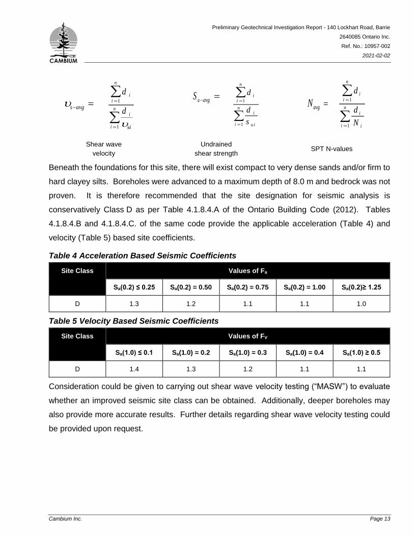
The parameters for determination of Site Classification for Seismic Site Response are set out in
Table 4.1.8.4A of the Ontario Building Code (2012). The classification is based on the
determination of the average shear wave velocity in the top 30 metres of the site stratigraphy,
where shear wave velocity (vs) measurements have been taken. Alternatively, the classification
is estimated on the basis of rational analysis of undrained shear strength (su) or penetration
resistance (N-values).
Preliminary Geotechnical Investigation Report - 140 Lockhart Road, Barrie
2640085 Ontario Inc.
Ref. No.: 10957-002
2021-02-02
Cambium Inc. Page 13
s avg
d
d
ii
n
i
sii
n
1
1
S u avg
d
d
s
ii
n
i
u ii
n
1
1
Navg
d
d
N
ii
n
i
ii
n
1
1
Shear wave
velocity
Undrained
shear strength SPT N-values
Beneath the foundations for this site, there will exist compact to very dense sands and/or firm to
hard clayey silts. Boreholes were advanced to a maximum depth of 8.0 m and bedrock was not
proven. It is therefore recommended that the site designation for seismic analysis is
conservatively Class D as per Table 4.1.8.4.A of the Ontario Building Code (2012). Tables
4.1.8.4.B and 4.1.8.4.C. of the same code provide the applicable acceleration (Table 4) and
velocity (Table 5) based site coefficients.
Table 4 Acceleration Based Seismic Coefficients
Site Class Values of Fa
Sa(0.2) ≤ 0.25 Sa(0.2) = 0.50 Sa(0.2) = 0.75 Sa(0.2) = 1.00 Sa(0.2)≥ 1.25
D 1.3 1.2 1.1 1.1 1.0
Table 5 Velocity Based Seismic Coefficients
Site Class Values of FV
Sa(1.0) ≤ 0.1 Sa(1.0) = 0.2 Sa(1.0) = 0.3 Sa(1.0) = 0.4 Sa(1.0) ≥ 0.5
D 1.4 1.3 1.2 1.1 1.1
Consideration could be given to carrying out shear wave velocity testing (“MASW”) to evaluate
whether an improved seismic site class can be obtained. Additionally, deeper boreholes may
also provide more accurate results. Further details regarding shear wave velocity testing could
be provided upon request.
Preliminary Geotechnical Investigation Report - 140 Lockhart Road, Barrie
2640085 Ontario Inc.
Ref. No.: 10957-002
2021-02-02
Cambium Inc. Page 14
4.7 Foundation Wall Backfill
To avoid frost adhesion and possible heaving, it is recommended that all foundation walls are
backfilled with non-frost susceptible granular material such as imported material meeting OPSS
Granular B Type I or II.
It is possible to reuse some of the existing cohesionless material as backfill such as in areas
underlying landscaped areas and those not sensitive to excess settlement. The reused material
should be tested by Cambium to determine if the level of frost susceptibility is within adequate
tolerance.
Where backfill will support areas of hard surfacing (pavements, walkways, etc.) the backfill
should be placed in maximum 200 mm thick lifts and compacted to at least 95% of the SPMDD
value.
4.8 Slab on Grade Design Parameters
All organic material and deleterious material must be removed prior to constructing the slab on
grade. These materials do not constitute an adequate subgrade for support of a slab on grade.
Compacted earth fill, engineered fill, the native sands, clayey silts, or glacial tills are suitable for
the support of a conventional slab on grade provided they are approved by Cambium.
The moduli of subgrade reaction appropriate for slab on grade design on the soils at the site are
as follows:
Compacted earth fill: 16,000 kPa/m
Engineered Fill: 22,000 kPa/m
Native, undisturbed soils: 30,000 kPa/m
The subgrade for the slab must be cut-neat, proof rolled, and inspected by Cambium, prior to
the placement of an aggregate base. The subgrade should be proof rolled using a static smooth
drum roller. If any soft or weak subgrade areas are identified, or if there are areas containing
excessive amounts of deleterious/organic material or moisture, they must be locally sub-
Preliminary Geotechnical Investigation Report - 140 Lockhart Road, Barrie
2640085 Ontario Inc.
Ref. No.: 10957-002
2021-02-02
Cambium Inc. Page 15
excavated and backfilled with approved clean earth fill or Engineered Fill such as OPSS Granular
B (Type I or II) and compacted to a minimum of 98% Standard Proctor Maximum Dry Density
(SPMDD).
It is necessary that the slab be provided with a capillary moisture barrier and drainage layer.
This is made by placing the slab on a minimum 200 mm layer of clear stone and nominally
compacted by vibration to a dense state. The upper 50 mm of clear stone may be replaced with
50 mm of OPSS Granular A to create a working surface.
4.9 Perimeter Drainage
Perimeter foundation drainage is not considered necessary for slab-on-grade structures
provided that the finished floor slab elevation is set above the exterior surface grades.
4.10 Site Servicing
4.10.1 Excavation
Excavations for proposed site services should adhere to the recommendations provided in
Section 4.1.
4.10.2 Bedding
The existing native soils and glacial till will provide adequate support for buried services on
conventional well graded granular base material. Where disturbance to the trench base has
occurred, such as due to groundwater inflow or construction activities, the disturbed materials
should be sub-excavated and replaced with suitably compacted granular fill.
Granular bedding material should consist of a conventional Class ‘B’ bedding, such as
OPSS.MUNI 1010 Granular A. The use of 19 mm clear stone (OPSS.MUNI 1004) as bedding
is also acceptable provided that the bedding is wrapped in suitable geotextile filter (Terrafix 360R
or equivalent). The bedding materials should be compacted to a minimum 95% of SPMDD.
Clear stone bedding material should be nominally compacted to a dense state.
Preliminary Geotechnical Investigation Report - 140 Lockhart Road, Barrie
2640085 Ontario Inc.
Ref. No.: 10957-002
2021-02-02
Cambium Inc. Page 16
4.10.3 Trench Backfill
In general, excavated soils encountered on site may be re-used as backfill, provided the moisture
content of these materials is within 2% of optimum to ensure adequate compaction, the trenches
are wide enough to accommodate large compaction equipment, and the soil is free of any
organic material. Soils with elevated moisture could be put aside to dry, tilled to reduce the
moisture content so that they can be effectively compacted, or could be mixed with dryer
material. Alternatively, materials of higher moisture content could be wasted and replaced with
imported material which can be readily compacted.
The backfill should consist of clean earth fill and should be placed in lifts of 150 mm thickness
or less and compacted to a minimum 95% of SPMMD (in settlement sensitive areas) and 90%
of SPMDD (in non-settlement sensitive areas) at a water content within 2% of optimum. Existing
earth fill and native soils will be difficult to place and compact successfully in narrow trench
excavations, where large compaction equipment could not operate. For narrow trench
excavations, it is recommended that free draining granular material, such as OPSS 1010
Granular ‘B’ be used in order to allow for adequate compaction using vibratory equipment. The
placement and inspection of any earth fill as backfill must be conducted under the full time
observation of Cambium.
4.11 Pavement Design Consideration
4.11.1 Subgrade Preparation
The performance of the pavement is dependent upon proper subgrade preparation. All topsoil
and organic materials should be removed. The subgrade should be proof rolled and inspected
by Cambium personnel. Any areas where rutting or appreciable deflection is noted should be
sub-excavated and replaced with suitable earth fill. The fill should be compacted to at least 98%
of SPMDD.
Preliminary Geotechnical Investigation Report - 140 Lockhart Road, Barrie
2640085 Ontario Inc.
Ref. No.: 10957-002
2021-02-02
Cambium Inc. Page 17
4.11.2 Typical Flexible Pavement Structure
The performance of the pavement is dependent upon proper subgrade preparation and
drainage. All fill materials should be removed down to native material and backfilled with
approved engineered fill or native material, compacted to 98% of SPMDD. The subgrade should
be proof rolled and inspected by a Geotechnical Engineer prior to placing the granular fill. Any
areas where rutting or appreciable deflection is noted should be subexcavated and replaced with
suitable fill. The fill should be compacted to at least 98% of SPMDD.
The recommended minimum pavement structure design has been developed for two traffic
loading scenarios; light duty and heavy duty. The light duty design is appropriate for areas where
no truck traffic is anticipated. The heavy duty design should meet the City of Barrie
Transportation Design Manual (2020) requirements and as a minimum, consist of the pavement
layers identified in Table 6. The heavy duty pavement structure recommended below assumes
that the annual average daily traffic (AADT) is less than 2,500, and is appropriate for areas where
heavy traffic or heavy loads are anticipated. If the predicted AADT is higher than that assumed,
Cambium should be contacted to reassess this recommendation.
It is noted that the minimum pavement structure may be reassessed following further
geotechnical investigations.
Table 6 Recommended Minimum Pavement Structure
Pavement Layer Light Duty (Light Vehicle Parking)
Heavy Duty (City of Barrie Designated Routes or Fire Truck Routes)
Surface Course Asphalt 40 mm HL3 or HL4 40 mm HL3 or SP 12.5
Binder Course Asphalt 50 mm HL8 70 mm HL8 or SP 19
Granular Base 150 mm OPSS 1010 Granular A 150 mm OPSS 1010 Granular A
Granular Subbase 300 mm OPSS 1010 Granular B 450 mm OPSS 1010 Granular B
Material and thickness substitutions must be approved by the Design Engineer. The thickness
of the subbase layer could be increased at the discretion of the Engineer, to accommodate site
conditions at the time of construction, including soft or weak subgrade soil replacement.
Preliminary Geotechnical Investigation Report - 140 Lockhart Road, Barrie
2640085 Ontario Inc.
Ref. No.: 10957-002
2021-02-02
Cambium Inc. Page 18
Granular layers should be placed in no more than 300 mm thick lifts and compacted to at least
98% of SPMDD (ASTM D698) standard. The granular materials specified should conform to
OPSS standards, as confirmed by appropriate materials testing.
The final asphalt surface should be sloped at a minimum of 2% to shed runoff. Abutting
pavements should be sawcut to provide clean vertical joints with new pavement areas.
Preliminary Geotechnical Investigation Report - 140 Lockhart Road, Barrie
2640085 Ontario Inc.
Ref. No.: 10957-002
2021-02-02
Cambium Inc. Page 19
5.0 Limitations
5.1 Design Review and Inspections
Cambium should be contacted to review and approve design drawings, prior to tendering or
commencing construction, to ensure that all pertinent geotechnical-related factors have been
addressed. It is important that onsite geotechnical supervision be provided at this site for
excavation and backfill procedures, deleterious soil removal, subgrade inspections and
compaction testing.
5.2 Changes in Site and Project Scope
This is a preliminary geotechnical engineering report intended for planning and preliminary
design purposes only. Additional boreholes and a detailed geotechnical engineering report are
required for detailed designs.
Subsurface conditions can be altered by the passage of sufficient time, natural occurrences, and
human intervention. In particular, consideration should be given to contractual responsibilities
as they relate to control of groundwater seepage, disturbance of soils, and frost protection.
The preliminary design parameters provided and the preliminary engineering advice offered in
this report are intended for use by the owner and its retained design consultants. These
interpretations made of the subsurface information, for preliminary geotechnical design
parameters, advice, and comments relating to constructability issues and quality control are not
complete for the project. Cambium should be retained to conduct further investigation at the site
for detailed designs.
Preliminary Geotechnical Investigation Report - 140 Lockhart Road, Barrie
2640085 Ontario Inc.
Ref. No.: 10957-002
2021-02-02
Cambium Inc. Page 20
6.0 Closing
We trust that the information contained in this report meets your current requirements. If you
have questions or comments regarding this document, please do not hesitate to contact the
undersigned reviewer at (705) 719-0700.
Respectfully submitted,
SEB/RG/bv
CAMBIUM INC.
Prepared By:
Reviewed By:
Blasco Vijayabaskaran, P.Eng.
Geotechnical Engineer/Project Manager
Rob Gethin, P.Eng.
Group Manager – Geotechnical Services
February 2, 2021
Preliminary Geotechnical Investigation Report - 140 Lockhart Road, Barrie
2640085 Ontario Inc.
Ref. No.: 10957-002
2021-02-02
Cambium Inc.
Appended Figures
P.O. Box 325, 52 Hunter Street EastPeterborough, Ontario, K9H 1G5
Tel: (705) 742.7900 Fax: (705) 742.7907www.cambium-inc.com
@A
@A
@A
@A
@A
@A
@ALOCKHART ROAD
WE
LH
AM
RO
AD
SAUNDERS ROAD
BA
YV
IEW
DR
IVE
BH103-20
BH104-20
BH105-20
BH106-20
BH107-20
BH102-20
BH101-20
BA
YV
IEW
DR
IVE
September 2020
1:5,000
Figure:Created by: Checked by:
Date:Project No.:
Scale: Projection:
NAD 1983 UTM Zone 17N
º
0 20 40 60 80 100
m
@A Borehole Location
Site (approximate)
LEGEND
Rev.:
O:\
GIS
\MX
Ds\1
09
00
-10
99
9\1
09
57
-00
2 2
640
08
5 O
nta
rio I
nc.
- P
aul R
acco -
GE
O -
140
Lo
ckh
art
Roa
d,
Barr
ie\2
020
-09
-29
FIG
1 -
Bore
ho
le L
ocation
Pla
n.m
xd
TLC
10957-002
RG 1
BOREHOLE LOCATION PLAN
Notes:
- Site is approximate and was obtained from the County of Simcoe onlineGIS.- Base mapping features are © Queen's Printer of Ontario, 2019 (this doesnot constitute an endorsement by the Ministry of Natural Resources or theOntario Government).- Distances on this plan are in metres and can be converted to feet bydividing by 0.3048.- Cambium Inc. makes every effort to ensure this map is free from errors butcannot be held responsible for any damages due to error or omissions. Thismap should not be used for navigation or legal purposes. It is intended forgeneral reference use only.
GEOTECHNICAL
GEOTECHNICALGEOTECHNICAL
GEOTECHNICAL
INVESTIGATION
INVESTIGATIONINVESTIGATION
INVESTIGATION
2640085 ONTARIO LTD.
140 Lockhart Road,
Barrie, Ontario
Preliminary Geotechnical Investigation Report - 140 Lockhart Road, Barrie
2640085 Ontario Inc.
Ref. No.: 10957-002
2021-02-02
Cambium Inc.
Appendix A
Borehole Logs
7550
SUBSURFACE PROFILE SAMPLE
Contractor:
Location: Elevation:
Hollow Stem Augers
140 Lockhart Raod, Barrie 17T: 606098m E, 4909398m N
Date Completed:
1 of 1
UTM:
Project No.:
September 3, 2020
10957-002
280.5
Page
Ele
vatio
n
(m)
Dep
th
Lith
olog
y
Description
Num
ber
Typ
e
% R
ecov
ery
SP
T (
N)
/ DC
PT
SP
T (
N)
/
% M
oist
ure
Walker Drilling Ltd.
Log of Borehole:Barrie
Peterborough
www.cambium-inc.com
Geotech Investigation - 140 Lockhart RoadProject Name:
RemarksInstallationWell
Client:
T: 866-217-7900
OshawaKingston
Method:
25 10 20 30 40
DC
PT
2640085 Ontario Inc.
BH101-20
Logged By: BW BWInput By:
280
279
278
277
276
275
274
273
0
1
2
3
4
5
6
7
8
GSA SS2:Gravel 3%Sand 43%Silt 41%Clay 13%
Borehole open and dry upon completion.
1A
1B
2
3
4
5
6
SS
SS
SS
SS
SS
SS
Topsoil: Dark brown silty sand, with organics, moist
Till: Weathered/disturbed
Till: Grey silt and sand, some clay, some gravel, dense to very dense, moist
Grey below
Borehole terminated at 5.0 mbgs.
50
100
0
100
70
70
4
9
40
50/280mm
50
35
7550
SUBSURFACE PROFILE SAMPLE
Contractor:
Location: Elevation:
Hollow Stem Augers
140 Lockhart Raod, Barrie 17T: 605925m E, 4909558m N
Date Completed:
1 of 1
UTM:
Project No.:
September 3, 2020
10957-002
287.6
Page
Ele
vatio
n
(m)
Dep
th
Lith
olog
y
Description
Num
ber
Typ
e
% R
ecov
ery
SP
T (
N)
/ DC
PT
SP
T (
N)
/
% M
oist
ure
Walker Drilling Ltd.
Log of Borehole:Barrie
Peterborough
www.cambium-inc.com
Geotech Investigation - 140 Lockhart RoadProject Name:
RemarksInstallationWell
Client:
T: 866-217-7900
OshawaKingston
Method:
25 10 20 30 40
DC
PT
2640085 Ontario Inc.
BH102-20
Logged By: BW BWInput By:
287
286
285
284
283
282
281
280
0
1
2
3
4
5
6
7
8
GSA SS3:Gravel 10%Sand 42%Silt 33%Clay 15%
Cobbles notted in cuttings at 2.3 mbgs.
Wet soils measured at 1.5 mbgs, caving at 2.3 mbgs.
1A
1B
2A
2B
2C
3
4
SS
SS
SS
SS
Topsoil: Dark brown silty sand, with organics, moist
Fill: Grey silty sand, with rootlets, compact, moist
Sand: Brown sand, trace silt, compact, moist
Till: Grey silty sand, some clay, trace gravel, dense to very dense, moist
Borehole terminated at 2.6 mbgs due to auger refusal.
90
90
100
20
12
28
44
50/125mm
7550
SUBSURFACE PROFILE SAMPLE
Contractor:
Location: Elevation:
Hollow Stem Augers
140 Lockhart Raod, Barrie 17T: 605786m E, 4909107m N
Date Completed:
1 of 1
UTM:
Project No.:
September 3, 2020
10957-002
276.0
Page
Ele
vatio
n
(m)
Dep
th
Lith
olog
y
Description
Num
ber
Typ
e
% R
ecov
ery
SP
T (
N)
/ DC
PT
SP
T (
N)
/
% M
oist
ure
Walker Drilling Ltd.
Log of Borehole:Barrie
Peterborough
www.cambium-inc.com
Geotech Investigation - 140 Lockhart RoadProject Name:
RemarksInstallationWell
Client:
T: 866-217-7900
OshawaKingston
Method:
25 10 20 30 40
DC
PT
2640085 Ontario Inc.
BH103-20
Logged By: BW BWInput By:
274
273
272
271
270
269
268
267
0
1
2
3
4
5
6
7
8
Borehole open and dry upon completion.
1A
1B
2
3
4
5
6
7
8
SS
SS
SS
SS
SS
SS
SS
SS
Topsoil: Dark brown silty sand, some gravel, with organics, moist
Silty Sand: Brown silty sand, some gravel, trace clay, compact to dense, moist
Clayey Silt: Grey brown clayey silt, trace sand, firm to stiff, moist
Till: Brown to grey brown silty sand, trace clay, trace gravel, very dense, moist
Borehole terminated at 8.0 mbgs.
80
30
80
80
90
80
100
100
31
38
25
7
9
50/125mm
50/255mm
50/230mm
7550
SUBSURFACE PROFILE SAMPLE
Contractor:
Location: Elevation:
Hollow Stem Augers
140 Lockhart Raod, Barrie 17T: 605785m E, 4909107m N
Date Completed:
1 of 1
UTM:
Project No.:
September 3, 2020
10957-002
277.1
Page
Ele
vatio
n
(m)
Dep
th
Lith
olog
y
Description
Num
ber
Typ
e
% R
ecov
ery
SP
T (
N)
/ DC
PT
SP
T (
N)
/
% M
oist
ure
Walker Drilling Ltd.
Log of Borehole:Barrie
Peterborough
www.cambium-inc.com
Geotech Investigation - 140 Lockhart RoadProject Name:
RemarksInstallationWell
Client:
T: 866-217-7900
OshawaKingston
Method:
25 10 20 30 40
DC
PT
2640085 Ontario Inc.
BH104-20
Logged By: BW BWInput By:
275
274
273
272
271
0
1
2
3
4
5
GSA SS5:Gravel 15%Sand 49%Silt 27%Clay 9%
Borehole open and dry upon completion.
1
2A
2B
3
4
5
6
SS
SS
SS
SS
SS
SS
Topsoil: Dark brown, silty sand, with organics, moist
Till: Weathered/disturbed
Till: Grey silty sand, some gravel, trace clay, very dense, moist
Borehole terminated at 4.6 mbgs due to auger refusal.
60
80
70
60
80
0
5
36
50/255mm
50/75mm
50/230mm
50/50mm
7550
SUBSURFACE PROFILE SAMPLE
Contractor:
Location: Elevation:
Hollow Stem Augers
140 Lockhart Raod, Barrie 17T: 605848m E, 4909259m N
Date Completed:
1 of 1
UTM:
Project No.:
September 4, 2020
10957-002
280.5
Page
Ele
vatio
n
(m)
Dep
th
Lith
olog
y
Description
Num
ber
Typ
e
% R
ecov
ery
SP
T (
N)
/ DC
PT
SP
T (
N)
/
% M
oist
ure
Walker Drilling Ltd.
Log of Borehole:Barrie
Peterborough
www.cambium-inc.com
Geotech Investigation - 140 Lockhart RoadProject Name:
RemarksInstallationWell
Client:
T: 866-217-7900
OshawaKingston
Method:
25 10 20 30 40
DC
PT
2640085 Ontario Inc.
BH105-20
Logged By: BW BWInput By:
279
278
277
276
275
274
273
272
0
1
2
3
4
5
6
7
8
GSA SS3:Gravel 18%Sand 46%Silt 27%Clay 9%
Borehole open and dry upon completion.
1
2
3
4
5
SS
SS
SS
SS
SS
Topsoil: Dark brown silty sand, trace clay, with organics, very loose, moist
Till: Weathered/disturbed
Till: Grey brown silty sand, some gravel, trace clay, very dense, moist
Borehole terminated at 3.1 mbgs due to auger refusal.
60
70
80
20
10
4
25
50/230mm
50/500mm
50/100mm
7550
SUBSURFACE PROFILE SAMPLE
Contractor:
Location: Elevation:
Hollow Stem Augers
140 Lockhart Raod, Barrie 17T: 606069m E, 4909148m N
Date Completed:
1 of 1
UTM:
Project No.:
September 4, 2020
10957-002
277.1
Page
Ele
vatio
n
(m)
Dep
th
Lith
olog
y
Description
Num
ber
Typ
e
% R
ecov
ery
SP
T (
N)
/ DC
PT
SP
T (
N)
/
% M
oist
ure
Walker Drilling Ltd.
Log of Borehole:Barrie
Peterborough
www.cambium-inc.com
Geotech Investigation - 140 Lockhart RoadProject Name:
RemarksInstallationWell
Client:
T: 866-217-7900
OshawaKingston
Method:
25 10 20 30 40
DC
PT
2640085 Ontario Inc.
BH106-20
Logged By: BW BWInput By:
275
274
273
272
271
270
269
268
0
1
2
3
4
5
6
7
8
Wet soils encountered at 2.3 mbgs.
3.7 m: Groundwater measurement on 22/09/2020
Cap
Bentonite Plug
PVC Standpipe
Sand Pack
PVC Screen
Cap
1
2A
2B
3A
3B
4
5
6
SS
SS
SS
SS
SS
SS
Topsoil: Dark brown silty sand, with organics, loose, moist
Silty Sand: Brown silty sand, compact, moist
Clayey Silt: Grey clayey silt, trace sand, very stiff, moist to wet
Till: Grey brown silty sand, trace clay,trace gravel, compact, wet
Borehole terminated at 5.0 mbgs
90
90
30
80
100
60
6
7
16
15
11
12
7550
SUBSURFACE PROFILE SAMPLE
Contractor:
Location: Elevation:
Hollow Stem Augers
140 Lockhart Raod, Barrie 17T: 605820m E, 4908951m N
Date Completed:
1 of 1
UTM:
Project No.:
September 4, 2020
10957-002
279.1
Page
Ele
vatio
n
(m)
Dep
th
Lith
olog
y
Description
Num
ber
Typ
e
% R
ecov
ery
SP
T (
N)
/ DC
PT
SP
T (
N)
/
% M
oist
ure
Walker Drilling Ltd.
Log of Borehole:Barrie
Peterborough
www.cambium-inc.com
Geotech Investigation - 140 Lockhart RoadProject Name:
RemarksInstallationWell
Client:
T: 866-217-7900
OshawaKingston
Method:
25 10 20 30 40
DC
PT
2640085 Ontario Inc.
BH107-20
Logged By: BW BWInput By:
277
276
275
274
273
272
271
270
0
1
2
3
4
5
6
7
8
GSA SS7:Gravel 3%Sand 61%Silt 31%Clay 5%
Borehole open and dry upon completion.
1
2A
2B
3
4
5
6
7
8
SS
SS
SS
SS
SS
SS
SS
SS
Topsoil: Dark brown silty sand, with organics, very loose, moist
Till: Weathered/disturbed
Till: Grey brown silty sand, trace gravel, trace clay, very dense, moist
Borehole terminated at 7.7 mbgs.
90
90
100
10
30
70
60
20
4
25
27
25
50/205mm
50/230mm
50/150mm
50/100mm
Preliminary Geotechnical Investigation Report - 140 Lockhart Road, Barrie
2640085 Ontario Inc.
Ref. No.: 10957-002
2021-02-02
Cambium Inc.
Appendix B
Physical Lab Results
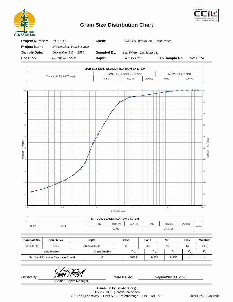
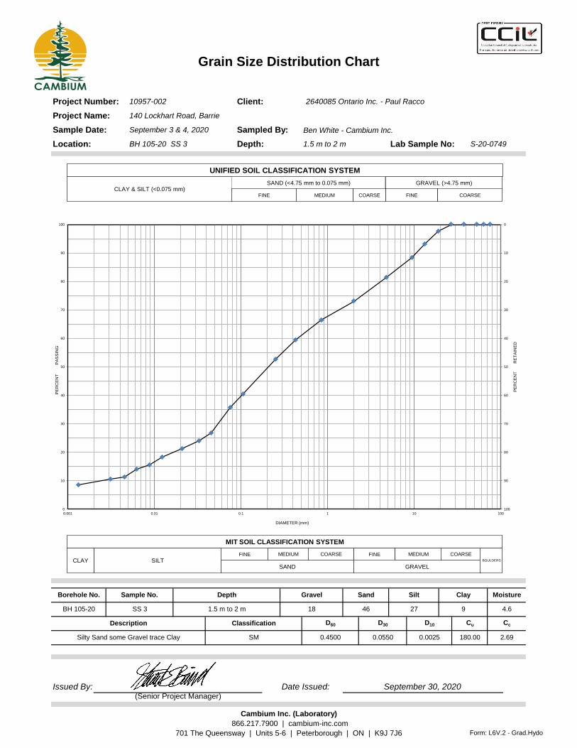
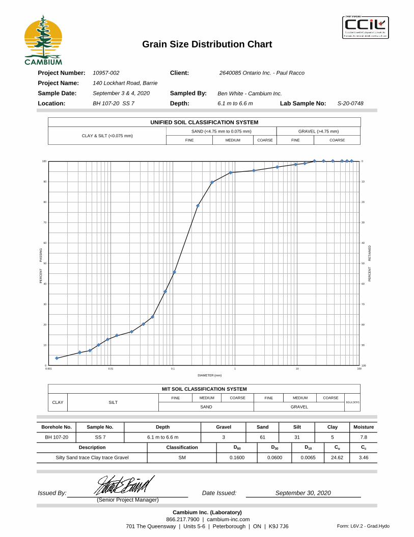
Grain Size Distribution Chart
Ben White - Cambium Inc.
Issued By: Date Issued:
Project Name:
Project Number:
0.6 m to 1.2 m
2640085 Ontario Inc. - Paul Racco
140 Lockhart Road, Barrie
10957-002
BH 101-20 SS 2
September 3 & 4, 2020
Depth:
Sampled By:
Client:
Lab Sample No: S-20-0751
Sample Date:
(Senior Project Manager)
September 30, 2020
Location:
Borehole No. Sample No. Depth Gravel Sand Silt Clay Moisture
11.2
Description Cc
BH 101-20 SS 2 0.6 m to 1.2 m 3 43
-Sand and Silt some Clay trace Gravel ML 0.098 0.028 0.000 -
Classification D60 D30 D10 Cu
41 13
0
10
20
30
40
50
60
70
80
90
1000
10
20
30
40
50
60
70
80
90
100
0.001 0.01 0.1 1 10 100P
ER
CE
NT
R
ET
AIN
ED
PE
RC
EN
T P
AS
SIN
G
DIAMETER (mm)
CLAY & SILT (<0.075 mm)SAND (<4.75 mm to 0.075 mm) GRAVEL (>4.75 mm)
FINE MEDIUM
UNIFIED SOIL CLASSIFICATION SYSTEM
COARSE FINE COARSE
CLAYFINE
SAND GRAVEL
BOULDERSSILTMEDIUM COARSE FINE MEDIUM COARSE
MIT SOIL CLASSIFICATION SYSTEM
Cambium Inc. (Laboratory)
866.217.7900 | cambium-inc.com
701 The Queensway | Units 5-6 | Peterborough | ON | K9J 7J6 Form: L6V.2 - Grad.Hydo
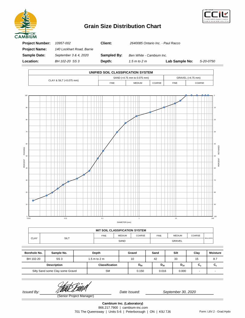
Grain Size Distribution Chart
Ben White - Cambium Inc.
Issued By: Date Issued:
Project Name:
Project Number:
1.5 m to 2 m
2640085 Ontario Inc. - Paul Racco
140 Lockhart Road, Barrie
10957-002
BH 102-20 SS 3
September 3 & 4, 2020
Depth:
Sampled By:
Client:
Lab Sample No: S-20-0750
Sample Date:
(Senior Project Manager)
September 30, 2020
Location:
Borehole No. Sample No. Depth Gravel Sand Silt Clay Moisture
8.7
Description Cc
BH 102-20 SS 3 1.5 m to 2 m 10 42
-Silty Sand some Clay some Gravel SM 0.150 0.016 0.000 -
Classification D60 D30 D10 Cu
33 15
0
10
20
30
40
50
60
70
80
90
1000
10
20
30
40
50
60
70
80
90
100
0.001 0.01 0.1 1 10 100P
ER
CE
NT
R
ET
AIN
ED
PE
RC
EN
T P
AS
SIN
G
DIAMETER (mm)
CLAY & SILT (<0.075 mm)SAND (<4.75 mm to 0.075 mm) GRAVEL (>4.75 mm)
FINE MEDIUM
UNIFIED SOIL CLASSIFICATION SYSTEM
COARSE FINE COARSE
CLAYFINE
SAND GRAVEL
BOULDERSSILTMEDIUM COARSE FINE MEDIUM COARSE
MIT SOIL CLASSIFICATION SYSTEM
Cambium Inc. (Laboratory)
866.217.7900 | cambium-inc.com
701 The Queensway | Units 5-6 | Peterborough | ON | K9J 7J6 Form: L6V.2 - Grad.Hydo
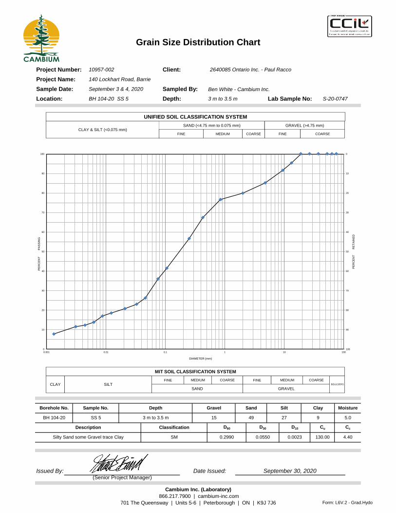
Grain Size Distribution Chart
Ben White - Cambium Inc.
Issued By: Date Issued:
4.40Silty Sand some Gravel trace Clay SM 0.2990 0.0550 0.0023 130.00
Classification D60 D30 D10 Cu
27 9BH 104-20 SS 5 3 m to 3.5 m 15 49
(Senior Project Manager)
September 30, 2020
Location:
Borehole No. Sample No. Depth Gravel Sand Silt Clay Moisture
5.0
Description Cc
Project Name:
Project Number:
3 m to 3.5 m
2640085 Ontario Inc. - Paul Racco
140 Lockhart Road, Barrie
10957-002
BH 104-20 SS 5
September 3 & 4, 2020
Depth:
Sampled By:
Client:
Lab Sample No: S-20-0747
Sample Date:
0
10
20
30
40
50
60
70
80
90
1000
10
20
30
40
50
60
70
80
90
100
0.001 0.01 0.1 1 10 100P
ER
CE
NT
R
ET
AIN
ED
PE
RC
EN
T P
AS
SIN
G
DIAMETER (mm)
CLAY & SILT (<0.075 mm)SAND (<4.75 mm to 0.075 mm) GRAVEL (>4.75 mm)
FINE MEDIUM
UNIFIED SOIL CLASSIFICATION SYSTEM
COARSE FINE COARSE
CLAYFINE
SAND GRAVEL
BOULDERSSILTMEDIUM COARSE FINE MEDIUM COARSE
MIT SOIL CLASSIFICATION SYSTEM
Cambium Inc. (Laboratory)
866.217.7900 | cambium-inc.com
701 The Queensway | Units 5-6 | Peterborough | ON | K9J 7J6 Form: L6V.2 - Grad.Hydo
Grain Size Distribution Chart
Ben White - Cambium Inc.
Issued By: Date Issued:
Project Name:
Project Number:
1.5 m to 2 m
2640085 Ontario Inc. - Paul Racco
140 Lockhart Road, Barrie
10957-002
BH 105-20 SS 3
September 3 & 4, 2020
Depth:
Sampled By:
Client:
Lab Sample No: S-20-0749
Sample Date:
(Senior Project Manager)
September 30, 2020
Location:
Borehole No. Sample No. Depth Gravel Sand Silt Clay Moisture
4.6
Description Cc
BH 105-20 SS 3 1.5 m to 2 m 18 46
2.69Silty Sand some Gravel trace Clay SM 0.4500 0.0550 0.0025 180.00
Classification D60 D30 D10 Cu
27 9
0
10
20
30
40
50
60
70
80
90
1000
10
20
30
40
50
60
70
80
90
100
0.001 0.01 0.1 1 10 100P
ER
CE
NT
R
ET
AIN
ED
PE
RC
EN
T P
AS
SIN
G
DIAMETER (mm)
CLAY & SILT (<0.075 mm)SAND (<4.75 mm to 0.075 mm) GRAVEL (>4.75 mm)
FINE MEDIUM
UNIFIED SOIL CLASSIFICATION SYSTEM
COARSE FINE COARSE
CLAYFINE
SAND GRAVEL
BOULDERSSILTMEDIUM COARSE FINE MEDIUM COARSE
MIT SOIL CLASSIFICATION SYSTEM
Cambium Inc. (Laboratory)
866.217.7900 | cambium-inc.com
701 The Queensway | Units 5-6 | Peterborough | ON | K9J 7J6 Form: L6V.2 - Grad.Hydo
Grain Size Distribution Chart
Ben White - Cambium Inc.
Issued By: Date Issued:
Project Name:
Project Number:
6.1 m to 6.6 m
2640085 Ontario Inc. - Paul Racco
140 Lockhart Road, Barrie
10957-002
BH 107-20 SS 7
September 3 & 4, 2020
Depth:
Sampled By:
Client:
Lab Sample No: S-20-0748
Sample Date:
(Senior Project Manager)
September 30, 2020
Location:
Borehole No. Sample No. Depth Gravel Sand Silt Clay Moisture
7.8
Description Cc
BH 107-20 SS 7 6.1 m to 6.6 m 3 61
3.46Silty Sand trace Clay trace Gravel SM 0.1600 0.0600 0.0065 24.62
Classification D60 D30 D10 Cu
31 5
0
10
20
30
40
50
60
70
80
90
1000
10
20
30
40
50
60
70
80
90
100
0.001 0.01 0.1 1 10 100P
ER
CE
NT
R
ET
AIN
ED
PE
RC
EN
T P
AS
SIN
G
DIAMETER (mm)
CLAY & SILT (<0.075 mm)SAND (<4.75 mm to 0.075 mm) GRAVEL (>4.75 mm)
FINE MEDIUM
UNIFIED SOIL CLASSIFICATION SYSTEM
COARSE FINE COARSE
CLAYFINE
SAND GRAVEL
BOULDERSSILTMEDIUM COARSE FINE MEDIUM COARSE
MIT SOIL CLASSIFICATION SYSTEM
Cambium Inc. (Laboratory)
866.217.7900 | cambium-inc.com
701 The Queensway | Units 5-6 | Peterborough | ON | K9J 7J6 Form: L6V.2 - Grad.Hydo