preliminary investigation jet fuel spill, white street
TRANSCRIPT

Preliminary Investigation Jet Fuel Spill - White Street Marine Corps Air Station Camp Lejeune, North Carolina Atec Job.No. 35-63481
6\ ,oa- u6/mfa~~~78
Prepared For:
Mr. Bob Alexander USMC Asst.; Chief of Staff Facilities Camp Lejeune, N.C. 28542-5001
I ,
. -
. .
a -

TABLE OF CONTENTS
PROJECT INFORMATION
FIELD TESTING Monitoring Well Installation Water Level and Fuel Thickness Determination Locations and Elevations
FINDINGS Subsurface Soil Conditions Fluid Levels Fuel Thickness
i- RECOMMENDED BECOVERY STRATEGY . & __ i.
SITE PRECAUTIONS - _-_ _
'6
CLOSURE
FIGURES 1) 2) 3) 4) 5) 6) 7) 8) 9)
Extent of Contamination Shoyn by Band Auger Borings, 1983 Monitoring Well Location Diagram Composite Potentlometrlc Surface Map Fuel Thickness Map Cross Section Location Map Cross Section A-A' Cross Sectloa B-B' Schematic of One-Pump, One-Well Recovery System Schematic of Two-Pump, Two-Well Recovery System
APPENDIX . Monitoring Well Details
.
.
‘.. . -

v V PBaTEcTINFORMATION
This study was verbally authorized on April 25, 1986 by Master Sergeant R. L. Dlngle of the Contracting Division as Purchase Order M67001-86-M1355. General project information has been provided by Mr. Bob Alexander, Environmental Engineer, and Mr. Fritz Acosta, Facilities Coordinator. We understand that a quantity of JP-5 jet fuel accumulated in a recently-Installed communications manhole on the east side of White Street at the Marine Corps Air Station. The fuel is known to have leaked from a pipeline, located 3 to 6 ft below grade on the west side of White Street, prior to its replacement in 1983 (Soils & Materials Engineers reports 051-83-354-A and 057-83-128). Several hand auger borings, performed in 1983, indicated that part of the study area was contaminated with JP-5 jet fuel. Up to 1.0 ft of fuel entered the hand auger borings (Figure 1).
Monitoring Well Installation I .
A system of 15 monitoring wells was Installed during May 6-11, 1986 (Figure 2). The wells are 15 ft deep, with a LO ft 0.01 inch slotted PVC screen at the base, and 7 ft of standpipe. Wells were installed with 6-l/2 inch 0. D. diameter augers,, and soil samples &are obtained at 5 ft intervals using a split-spoon sampler. Sand was use@ as--backfill to 2 ft above the screen, followed by 1 ft of bentonite- and up?*: 2 ft of cement.
Water Level'and Fuel Thickness Determination .L
Water levels and the thicknesses of-the JP-5 fuel layer were measured in each well using both water-sensitive and oil-sensitive pastes (Kolor Kut Water Finding Paste and Kolor Kut Gasoline Gauging Past) and a weighted fiberglass tape. The pastes were applied to opposite sides of the tape and lowered into the well casing. The use of both pastes allowed an accurate determination of the depth to water and the thickness of any JP-5 fuel present.
Locations and Elevations
Locations and elevations for the wells were determined using a theodolite and an electronic distance measuring device (EDM). A temporary benchmark level of El 20.00 was assigned the top cap of fire hydrant l-72-18 located on the east side of White Street, immediately south of the exit drive of Building 4141. Elevations for the tops of the metal protective well casings were obtained using this temporary benchmark.
-

v V Department of Navy
..lune 2, 1986 Page Two
I
z f
‘f
e 4 . .
FINDINGS
Subsurface Soil Conditions
Three soil units were encountered. The surface layer is a 0.0 ft to 10.5 ft thick layer of very loose to firm, black to brown, dry to moist, silty (O- 40x), fine- to medium-grained SAND (SM or SP). Beneath this granular soil is a 6.0 ft or thicker, very soft to firm, gray to mottled brown and gray, moist to wet, silty CLAY (CD/CL). In boreholes W-2, W-3, W-8, W-9, W-10, and W-11 this cohesive soil unit extended to termination depths of 15.0 ft. At the base of the borings in the remainder of the boreholes is a very loose to firm, gray, wet to saturated, silty (0-15X) fine- to coarse-grained SAND (SM or SP). Details of subsurface soil conditions are included on the Monftqring Well Details Diagrams in the Appendix. Two cross sections showing subsurface conditions are included as Figures 6 and 7.
Fluid Levels
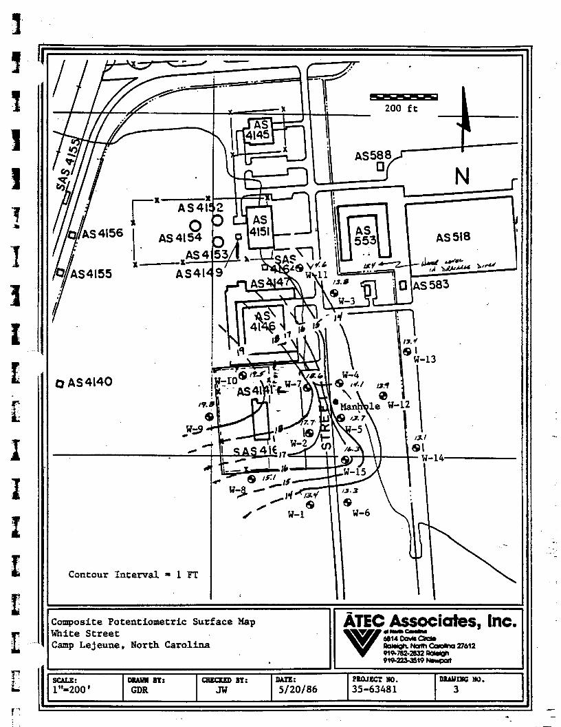
Fluid levels in the wells ranged fro& 7.0-ft to 13.5 ft below grade two to six days after installation. --A‘contoucf map of the composite potentlometric surface is included as Figure 3. s fluid level in W-5 bas been corrected for the effects of the 0.8 specific Gavity of the, JP-5 fuel.
The higher potentiometric surfaces noted in wells W-2, W-7, W-9, and W-10 may have been influenced by perched water in'the' nearsurface silty SAND. Other factors which indicate water may be perched, at least temporarily are the relatively high water level in the drainage ditch located to the east and the high water levels encountered in shallow soil borings performed in late 1983. During drilling operations, however, no free water was encountered In the upper silty SAND, probably due to the relatively dry winter and spring months. The occasional presence of fluid in the upper silty SAND suggests that some combination of percolation, evaporatfon, or drainage will remove perched fluids. Some amount of fluid .transfer across the silty CUY is present since fuel tended to occur la both upper and lower granular soils whenever .: contamination was detected.
Fuel Thickness
Fuel thicknesses ranged from 0.0 ft to 8.9 ft with fuel being detected in two areas: at the northern edge of the study area (W-3 and W-11) and in the .center of the study area near the communications manhole and W-5. Only observation wells W-11, W-Q, and W-5 had measurable amounts of fuel (0.18 ft, 0.16 ft, and 8.9 ft respectively), while W-3 and W-15 bad only a trace of . fuel. Wells W-2 and W-6 had detectable fuel odors in split-spoon samples obtained during drilling operations, but showed no detectable accumulation of fuel in the observation well. A fuel thickness map is included aa Figure 4.

Department of the Navy June 2, 1986 Page Three
T’” 1 :* ._
Thickness of fuel within the aquifer is less than the thickness measured in the observation well. Published studies (De Pastrovich, et al., 1979, and Kramer, 1982) report that fuel thickness measured in a well Is two to four times greater than the thicknesses In the aquifer due to capillary action.
BlixoMMKNDED RECOVERY STRAYEGY
The presence of 8.9 ft of fuel in W-5 and relatively minor amounts or no fuel in nearby wells indicates a severe, but localized, contamination problem. A major goal of most aquifer restoration programs Is to concentrate the pollutant to facilitate fts removal. Apparently natural processes. have already achieved this goal. The recovery procedure will therefore be largely concerned with the removal of the JP-5, rather than containment of a spreading plume.
The fuel can be removed safety and efficiently by the use of recovery wells. The number of recovery yells require#, their location, and the well design can be properly defined only after perf@?ming.permeability tests to determine the aquifer characteristics. -These tests will also enable an evaluation of the relationship between the upper and l&r sands. Only at the conclusion of the aquifer tests can the recovery system be properly designed.
Two possible recovery well systems-are proposed: A single-pump system utilizing single recovery wells, and a two-pump system utilizing single recovery wells.
A single-pump system can utilize a small (i.e. less than 8 inch) diameter well (Figure 8). It is generally less expensive to construct due to the smaller diameter of the well, the use of a single pump, and the use of a simple mechanical float switch. Disadvantages of the system include the necessity of a surface product/water separator and associated emulsification of product due to fluid agitation.
A two-pump system utilizes a large (26+ inch) diameter well (Figure 9). This system is generally the most desirable recovery arrangement due to the continuous isolation of product from water and the automation of the system. The disadvantages include the higher cost of well installation, expensive Pumps, and potential problems with the complex automation system.
SITE pRIxmTIoIvs
c Buried cable housings, particularly those utilizing petroleum-soluble WC cements, will be susceptible to damage in the contaminated area even after the majority of the .fuel has been removed. Kramer (1982) states that buried
y? telephone cables are even susceptible to damage from petroleum vapors. t
.

z
9 1 .
Department of the Navy June 2, 1986 Page Four
A recovery system is designed to remove fuel which has migrated into the - wellbore. It should be noted that a volume of fuel equal to approximately 15 percent of the total porosity of the soil will be retained by saturated soil (API, 1982). This residual fuel will be concentrated and mobilized during water table fluctuations, thereby creating a hazard to any buried cables within the fluctuation (vadose) zone. It is therefore important that any utilities installed in:the area be designed to withstand exposure to fuel.
CLOSURE
These analyses and recommendations are, of necessity, based on the concepts made available to us at the time of the writing of this report and on, the assumption that site and subsurface conditions which existed at the. time of the subsurface exploration are representative of general conditions across the site.
We have appreciated being of servife to you in the subsurface exploration phase of this project and are prep&d to assist you during the coustruction phases as well. If you have any q&stions concerning this report or any of our testing, inspection; d&sign am consulting services, please do not hesitate to contact this office.
. - .- Very truly yours;
-*
H
GDB/GPA/mr
.
Gary D. Rogers Senior Geologist
Engineering Department Manager

3
I 7 A
I z i:
Department of the Navy June 2, 1985 Page Five
BIBLIOGRAPHY
API, 1972, The Migration of Petroleum Products in Soil and Groundwater - Principles and Countermeasures,i API publication 4149, American Petroleum Institute, Washington.
Blake, Steven B., and R. W. Lewis, 1983, Underground Oil Recovery, Groundwater Monitoring Review, Spring Issue, pa 40-46.
Kramer, William H., 1982, Groundwater Pollution from Gasoline, Groundwater Monitoring Review, Spring Issue, pa 18-22.
Soil and Materials Engineers, 1983, JP-5 Fuel Line Investigation, S&M8 Job # 057-83-128.
Soil and Materials Engineers, 1983,&eaked Fuel Inventofy, S&ME Job # 051-83- 354-A. & -x
_-_ - L
-

# ‘%a. 8+00
Pit No. 1 0 A Fuel 0 n ‘AN.F.D.. hN.F.0. 4
sta. W+oD sta. 1160 Sta.U+iS Sta. 12+65 str. 1490
:pTE: whned Clrclrr or Triangles Indlute Presence of Furl.
p!iif 0 Old Hand Auger Probe
0 New Hand Auger Probe
l Proposed Hand Auger Pmbe
N.F.0. - No Fuel Detected
Adapted from S&ME Report 051-83-354-A
Extent of Contamination Shown by Hand Auger
SCALE: DNLUH NT: CaNum BY: DAR: PmJEcr ND. DBAUMC ND.
Graphic GDR GPA 5/20/86 35-63481 1 . ,

0 AS4140
,
-- - I 1 8
rJ-8
8 W-l
Monitoring Well Location Diagram
CAL& DIIylBY: aucxED BY: DATE: 1"-200 '
PnQJEcT No. GDR
mAim?G No. GPA 5120186 35-63481. 2
.
‘I / - . 1
III - 111
Contour Interval = 1 FT
I
bnposite Potentiometric Surface Map ATEC Jhite Street v
v V
dlmmclk Zamp Lejeune, North Carolina 4814DOUlSC3Cb
-$w$ pg-&-&' 27612
. v1w2&0 w I t SCALX: DaAwl BY: CaxcxxD BY: DAIX: PROJECT m. DRAuIm No.
1"=200 GDR Jw S/20/86 35-6348 1 3
-

r X
AS41 It I
0 AS 4154 . * 1 AS4 x-x-
AS414
0 AS4140
EXPLANATION -Contours
l l l l a* Trace Amounts - -- Measurable Amoun - 8 FT Contour
I q
M Manhole T Trace
* 00 Fuel Odor il&ing I)rfllJ: II
Fuel Thickness Map White Street Camp Lejeune, North Carolina
Ccw: 1"=200 Tkmr -%Yt
M?t: 5/20/86
PIUUCCT no. 35-63481 mAuMc Mu.
4

i
-X
I AS x
c I II I i
u
0 AS4140
-
1
Cross Section Location Map White Street Camp Lejeune, North Carolina I
. SCALE: mAulI BY: l"-200'
axam BY: DATX: GDR Jw 5/20/86
PXOJXCT moo. mAfmG m. 35-63481 5
b
.

.
OIL - WATER .
SEPARATOR 1 . . .
BENTONITE SEAL
‘b NAT WE
.
BACKFILL - .
i \ 3 $ . . .
GRAVEL l
PACK >
PRODUCT a- l .
. w :* a.
.
. . ,** 0. 9 .* ;.: . . -* :- $ . .
I
w FLOAT SwiTCn
METAL ROD /
CASING w
. Sut3tdERi;B~E PUMP
CONflNfJOUS SLOT / SCREEN
Adapted from Blake and Lewis, 1983
Ull
BULB: DBAUB BY: CHmcED BY: DATE: PuoJEcr No. DIUUIW: No.
NT’S GDR GPA 5/20/86 35-63481 8
- \ - '; -

/ Seal ( 0s required 1
.
Native Backloll
PROOUCT r WI I I
,Grokl Pack
Product Detection Continuqus Slot
I
Adapted from Blake and Lewis, 1983
Schematic of Two-Pump, One-Well Recovery System
&TEC Associates, Inc. v v
dma- Il4bul8ckb Ro~Numcolomo27612 9l9-7a2-zm2 M
SCALE: NTS
Duun BT; GDR
QECICEP BY: GPA
II 91sza-3sl9~ 1
DhTE: PWJECT No. DIbumG No. S/20/86 3506348 1 9

cc. I
m f

r
i i g
I I I
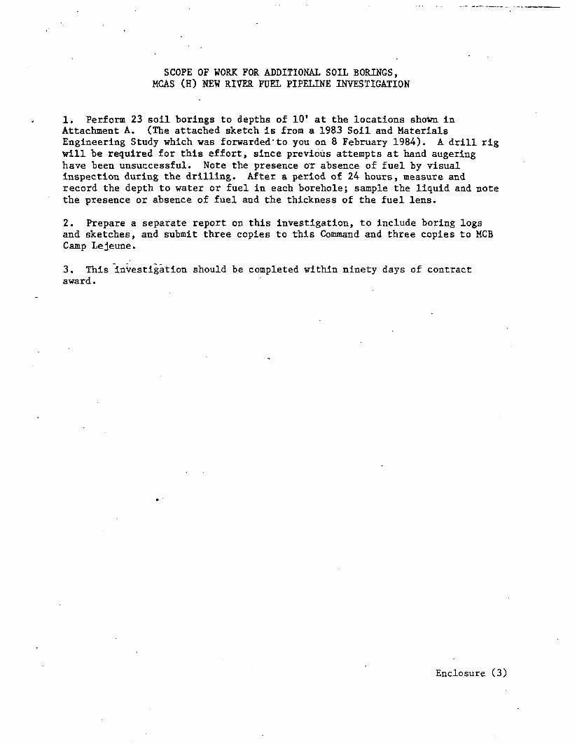
SCOPE OF WORK FOR ADDITIONAL SOIL BOEINGS, MCAS (H) NEW RIVER FUEL PIPELINE INVESTIGATION
. Perform 23 soil borings to depths of 10' at the locations shown in ~&a&meat A. (The attached sketch is from a 1983 Soil and Materials Engineering Study which was forwarded'to you on 8 February 1984). A drill rig will be required for this effort, since previous attempts at hand augering have been unsuccessful. Note the presence OT absence of fuel by visual inspection during the drilling. After a period of 24 hours, measure and record the depth to water or fuel in each borehole ; sample the liquid and note the presence or absence of fuel and the thickness of the fuel lens.
2. Prepare a separate report on this investigation, to include boring logs and sketches, and submit three copies to this Command and three copies to MCB Camp Lejeune.
3. This investigation should be completed within ninety days of contract award.
Enclosure (3)

Fueling Area Fueling Area '
\
i
Fuel Odor
Fuel Odor
N.F.D
N.F.0
Fuel Odor
Fuel Odor
7" Fuel -----
3” Fuel
*
. Stalt Fuel
69 Fuel Odor-e
II-1 Fuel
Cas ing
Prc
N.F.D.0
Fuel Odor '
LEGEND.
Fuel, Odor &
2’-1” 2’-1” I’-9” Fuel 9 Fuel l
B &!I n ~~~b~and Auger
0 New Hand Auger NOTE: Darkened Circles or Triangles Indicate
Presence of Fuel. ' @9 Proposed Hand Auger probe
q Fuel Skid
N.F.D. - No. Fuel Detected
PROJECT SOIL8 MATERIAL ENUNEERS, INC. SCALE: 1 II = 100’ Fuel Pipeline fnvestigatipn Cam LcJeune
RALEIGH , NORTH CAROLINA JOB NO: 051-83-354-A
Jhcisonv.i),le, Eloyth karolin? 6 FIG NO: 8 Ski-8 1 ? 1’ ). , ,,.).‘u~;j,,ql ‘; 4 , s,i.. ; : f 1 , I