preliminary results for multi-service support in link...
TRANSCRIPT

Call: H2020-ICT-2014-2
Project reference: 671660
Project Name:
Flexible Air iNTerfAce for Scalable service deliver y wiThin wIreless Communication networks of the 5th Generation (FANTA STIC-5G)
Deliverable D3.1
Preliminary results for multi-service support in link solution adaptation
Date of delivery: 30/05/2016 Version: 1.0.0
Start date of project: 01/07/2015 Duration: 24 months

Document properties:
Document Number : D3.1
Document Title: Preliminary results for multi-service support in link solution adaptation
Editor(s): Xitao Gong (HWDU)
Authors: Frank Schaich, Thorsten Wild, Rana Ahmed, Yejian Chen (ALU), Nicolas Cassiau, Jean-Baptiste Doré, Dimitri Kténas (CEA), Mònica Navarro, Màrius Caus, Pau Closas (CTTC), Johannes Dommel, Sameh Eldessoki and Lars Thiele (HHI), Xitao Gong, Malte Schellmann, Onurcan Iscan (HWDU), Honglei Miao, Leonardo Gomes Baltar, Yang Yang (Intel), Jaakko Vihriälä, Juha Karjalainen (NOKIA), Hao Lin, Dinh-Thuy Phan Huy (ORG), Catherine Douillard, Charbel Abdel Nour (TB), Guillaume Vivier, Serdar Sezginer (SEQ), Mohammed Al-Imari, Belkacem Mouhouche, Shangbin Wu (SEUK), Kostas Tsagkaris, Panagiotis Demestichas, Andreas Georgakopoulos, Evangelos Kosmatos, Vassilis Foteinos, Ioannis-Prodromos Belikaidis, Aikaterini Demesticha, Evaggelia Tzifa, Vera Stavroulaki, Serafim Kotrotsos, Vassaki Stavroula, Kritikou Panagioula, Pilichos Dimitrios, Ropodi Athina, Evangelos Argoudelis (WINGS).
Contractual Date of Delivery: 30/05/2016
Dissemination level: PU1
Status: Final
Version: 1.0.0
File Name: FANTASTIC-5G_D31
1CO = Confidential, only members of the consortium (including the Commission Services)
PU = Public

Abstract
FANTASTIC-5G advocates a single air interface for 5G, which is flexible, versatile, and scalable in order to address the requirements of the beyond 2020 era. The flexibility of FANTASTIC-5G air interface allows the support of a multitude of foreseen and unforeseen services/applications with diverse requirements, such as Mobile Broadband (MBB), Massive Machine Communications (MMC), Mission Critical Communications (MCC), Broadcast/Multicast Communications (BMS) and Vehicular to anything communications (V2X).
The scope of this Work Package is the link design which focuses on the PHY and MAC layer research. The objective is to provide a holistic link solution that can be flexibly adapted to five core services (MBB, MMC, MCC, BMS and V2X). This flexible adaptation to different services works under the assumption that the air interface has knowledge on the service type of each data flow, paving the way for efficient cross layer optimization. The main focus of this WP is on the technical aspects that are tightly related to future 5G standardization, rather than a general algorithmic investigation.
This document represents the first deliverable on the link design research in the FANTASTIC-5G project, which presents the project’s preliminary technical research results on the link solutions for a service-specific air interface design. In this document, we first describe service-specific baseline solutions for the five core services based on 3GPP latest releases with some not-yet-standardized but straightforward enhancements. After recalling the primary challenges for those services, we provide preliminary results on the service-specific solutions, which will in the succeeding steps be harmonized towards a holistic air interface design embracing the five core services.
Keywords
5G, air interface design, physical layer procedure, massive machine communication, mobile broadband, mission critical communication, multicast broadcast service, multiple service support, vehicular to anything, waveforms.

FANTASTIC-5G Deliverable D3.1
Dissemination level: Confidential Page 4 / 213
Executive Summary
This document represents the first report on the link design research in the FANTASTIC-5G project, which presents the project’s first technical research results on the link solutions for a service-specific air interface design. Five core services have been identified by the project, constituting the broad range of applications foreseen for future 5G systems. These five core services are named as mobile broadband (MBB), massive machine communication (MMC), mission critical communication (MCC), vehicle-to-anything (V2X) and broadcast multicast service (BMS). For each of those core services, the FANTASTIC-5G project intends to design a service-specific air interface, responding to the particular requirements and meeting all the desired KPIs while achieving a high system efficiency. Preliminary results on the link design for these service-specific air interfaces are presented in this report. In a second step planned for future work, the service-specific air interface solutions will be harmonized towards an overall solution for a multi-service air interface, offering a reasonable trade-off between sufficient flexibility to address all the needs of the diverse supported services and the overall system complexity, thus yielding a highly versatile yet cost-efficient system.
In this document, we first recall the primary challenges and requirements for each service and then describe a baseline solution based on 3GPP latest releases with some not-yet-standardized but straightforward evolutions. As the key part of this document, we present a set of novel technologies, which have been tailored to address the specific needs of the five core services. To underpin the high potential of these solutions, appropriate evaluation results based on selected toy scenarios are provided where available. It should be noted that different technology solutions are not always complementary, but may be concurrent, as some solutions address identical problems with similar means. Work towards a harmonization of those concurrent solutions has not yet been carried out, but this will be addressed in future studies. In a succeeding conclusion, we elaborate on how the novel technologies presented earlier can become part of the service-specific air interface design and which benefits and performance gains they can yield compared to the baseline.

FANTASTIC-5G Deliverable D3.1
Dissemination level: Confidential Page 5 / 213
Table of Contents
1 Introduction......................................................................................................................... 20 1.1 Objectives and scope of the document......................................................................... 20 1.2 Structure of the document ............................................................................................ 21
2 Challenges, requirements and baseline design for core services .................................... 21 2.1 Mobile broadband ........................................................................................................ 21 2.1.1 Requirements and challenges ................................................................................. 21 2.1.2 Baseline design ....................................................................................................... 22 2.1.2.1 System bandwidths, transmission resources, frame structure and waveforms
........................................................................................................................... 22 2.1.2.2 Downlink and uplink physical channels and signals ......................................... 22 2.1.2.3 Summary of technology components ................................................................ 23 2.2 Massive machine communication ................................................................................ 23 2.2.1 Requirements and challenges ................................................................................. 23 2.2.2 Baseline design ....................................................................................................... 24 2.3 Mission critical communication ................................................................................... 24 2.3.1 Requirements and challenges ................................................................................. 24 2.3.2 Baseline design ....................................................................................................... 25 2.3.2.1 Protocol enhancements for fast uplink access solutions .................................... 25 2.3.2.2 Physical layer enhancements for TTI shortening .............................................. 26 2.4 Broadcast multicast services ........................................................................................ 27 2.4.1 Requirements and challenges ................................................................................. 27 2.4.2 Baseline design ....................................................................................................... 28 2.4.2.1 Physical layer frame structure ........................................................................... 28 2.4.2.2 Physical channels and signals ............................................................................ 29 2.4.2.3 PHY procedure .................................................................................................. 29 2.5 Vehicular-to-anything .................................................................................................. 30 2.5.1 Requirements and challenges ................................................................................. 30 2.5.1.1 Challenges for V2X ........................................................................................... 31 2.5.2 Baseline design ....................................................................................................... 31 2.5.2.1 IEEE 802.11p (DSRC) activities ....................................................................... 31 2.5.2.2 ETSI ES 202 663 ............................................................................................... 31 2.5.2.3 3GPP LTE and V2X evolution .......................................................................... 32
3 Enhanced technology components .................................................................................... 32 3.1 New waveform ............................................................................................................. 33 3.1.1 Motivation and advantages ..................................................................................... 33 3.1.2 New waveform candidates ...................................................................................... 34 3.1.3 Special application of positioning with waveforms ................................................ 43 3.2 Channel coding and advanced AMC ........................................................................... 44 3.2.1 Motivation .............................................................................................................. 44 3.2.2 Design of enhanced Turbo Codes for 5G ............................................................... 44 3.2.3 Link adaptation using NB-LDPC codes ................................................................. 46 3.2.4 Low-Latency channel coding ................................................................................. 47 3.2.5 Frequency quadrature amplitude modulation ......................................................... 48 3.2.6 Conclusion .............................................................................................................. 49 3.3 Low PAPR design ........................................................................................................ 49 3.3.1 Motivation .............................................................................................................. 49 3.3.2 Proposed solutions .................................................................................................. 50 3.3.3 Conclusion .............................................................................................................. 51 3.4 MIMO techniques for new waveforms ........................................................................ 51 3.4.1 Enhanced spatial modulation .................................................................................. 51 3.4.2 Alamouti scheme for FBMC .................................................................................. 52

FANTASTIC-5G Deliverable D3.1
Dissemination level: Confidential Page 6 / 213
3.4.3 MIMO compatibility for P-OFDM ......................................................................... 54 3.4.4 MIMO for vehicular communications .................................................................... 55 3.5 Service Driven frame design ........................................................................................ 56 3.5.1 Motivation .............................................................................................................. 56 3.5.2 Design principles .................................................................................................... 56 3.5.3 Proposed solutions .................................................................................................. 58 3.6 Physical layer procedure and multiple access .............................................................. 61 3.6.1 Preamble design ...................................................................................................... 62 3.6.1.1 Preambles for UL massive access ..................................................................... 62 3.6.1.2 Preamble design for downlink control channel ................................................. 63 3.6.2 FBMC based PRACH ............................................................................................. 63 3.6.3 Service specific DL synchronization channels for efficient support of narrow-
band devices ........................................................................................................... 64 3.6.4 Physical layer procedures of integrated air interface .............................................. 65 3.6.5 RACH for MMC ..................................................................................................... 66 3.6.6 TA-free asynchronous multiple access ................................................................... 66
4 Conclusions .......................................................................................................................... 67
5 References ............................................................................................................................ 69
6 Appendix .............................................................................................................................. 79 6.1 Waveform .................................................................................................................... 79 6.1.1 Service driven flexible waveform design UF-OFDM related outcomes ................ 79 6.1.1.1 Low complexity implementation of UF-OFDM (Tx and Rx) ........................... 79 6.1.1.2 Concurrent support of different subcarrier spacing ........................................... 83 6.1.1.3 Support of transmissions with relaxed synchronization .................................... 83 6.1.1.4 Performance of UF-OFDM in frequency-selective/delay-spread channels ....... 85 6.1.1.5 On the co-existence of UF-OFDM and CP-OFDM ........................................... 87 6.1.2 QAM-FBMC with Multiple Prototype Filters ........................................................ 89 6.1.2.1 System model .................................................................................................... 89 6.1.2.2 Complexity analysis .......................................................................................... 90 6.1.2.3 Performance evaluation ..................................................................................... 90 6.1.3 FS-FBMC architecture and parameterization ......................................................... 93 6.1.3.1 Architecture of the receiver ............................................................................... 93 6.1.3.2 Parametrization of the waveform ...................................................................... 97 6.1.4 FC-OFDM uplink solution and evaluation ............................................................. 99 6.1.4.1 Pre-IFFT part ..................................................................................................... 99 6.1.4.2 Post-IFFT part ................................................................................................. 100 6.1.4.3 Performance evaluation ................................................................................... 100 6.1.5 Pulse-shaped OFDM: concept and performance .................................................. 103 6.1.5.1 Motivation and concept ................................................................................... 103 6.1.5.2 Low complexity implementation ..................................................................... 105 6.1.5.3 Support of flexible spectral usage ................................................................... 105 6.1.5.4 Support of asynchronous TA-free transmission .............................................. 106 6.1.5.5 Support of high mobility scenarios .................................................................. 107 6.1.6 Positioning capabilities of candidate waveforms .................................................. 108 6.2 Channel coding, advanced AMC and HARQ ............................................................ 115 6.2.1 Precoded Turbo codes........................................................................................... 115 6.2.2 Frequency Quadrature Amplitude Modulation ..................................................... 117 6.2.3 NB-LDPC ............................................................................................................. 118 6.2.4 Mapping schemes for SISO and MIMO communication systems ........................ 121 6.2.4.1 SISO ................................................................................................................ 121 6.2.4.2 MIMO .............................................................................................................. 122 6.2.5 Link adaptation with adaptive code and modulation ............................................ 123 6.2.5.1 Numerical results ............................................................................................. 125

FANTASTIC-5G Deliverable D3.1
Dissemination level: Confidential Page 7 / 213
6.3 Low PAPR design ...................................................................................................... 126 6.3.1 PAPR Reduction for FBMC ................................................................................. 126 6.3.2 PAPR performance for pulse-shaped OFDM ....................................................... 128 6.4 MIMO technique for new waveforms........................................................................ 129 6.4.1 Alamouti scheme for FBMC ................................................................................ 129 6.4.1.1 Proposed solution - Alamouti schemes for FBMC using time reversal
properties ......................................................................................................... 130 6.4.2 P-OFDM performance in supporting MIMO ........................................................ 139 6.4.3 MIMO for connected vehicles .............................................................................. 141 6.4.3.1 Cost in transmit power of fast moving connected vehicles ............................. 142 6.4.3.2 Cost in spectrum of fast moving connected vehicles....................................... 145 6.4.3.3 Conclusion ....................................................................................................... 147 6.5 Service driven frame design ...................................................................................... 148 6.5.1 Frame design for enabling efficient multi-service support ................................... 148 6.5.2 Integrated frame design to support multiple services ........................................... 150 6.5.2.1 Service specific resource partitions ................................................................. 150 6.5.2.2 Extended resource block definitions................................................................ 151 6.5.2.3 Extended DMRS Pattern ................................................................................. 153 6.5.3 Frame design based on service requirements ....................................................... 154 6.6 Physical layer procedure and multiple access ............................................................ 157 6.6.1 Preamble design for 1-stage and 2-stage protocols (UL) and user identification
in DL control channels.......................................................................................... 157 6.6.1.1 Signal model .................................................................................................... 158 6.6.1.2 Detection and Estimation ................................................................................ 159 6.6.1.3 Numerical Results ........................................................................................... 161 6.6.1.4 Summary.......................................................................................................... 163 6.6.2 FBMC based PRACH ........................................................................................... 163 6.6.2.1 LTE PRACH ................................................................................................... 163 6.6.2.2 FBMC transceiver ........................................................................................... 164 6.6.2.3 Time-spectral efficiency .................................................................................. 166 6.6.2.4 Accuracy of the estimation .............................................................................. 167 6.6.2.5 False alarms and non-detections ...................................................................... 168 6.6.3 Service specific DL synchronization channels for efficient support of narrow-
band devices ......................................................................................................... 169 6.6.4 Physical layer procedures of integrated air interface ............................................ 172 6.6.4.1 Synchronization signal and PBCH of coverage enhancement ........................ 172 6.6.4.2 Resource partition specific discovery signal for RRM .................................... 175 6.6.4.3 Extended primary partition SIB for secondary partition signalling ................. 176 6.6.4.4 Multiple service-specific resource partition aggregation ................................ 176 6.6.5 RACH for MMC ................................................................................................... 181 6.6.6 TA-free asynchronous multiple access ................................................................. 182 6.7 Physical layer design for core services ...................................................................... 185 6.7.1 Mobile Broadband ................................................................................................ 185 6.7.1.1 Requirements and Challenges ......................................................................... 185 6.7.1.2 Baseline design ................................................................................................ 189 6.7.1.3 Summary of technology components .............................................................. 190 6.7.2 Massive machine communication ......................................................................... 191 6.7.2.1 Requirements and challenges .......................................................................... 191 6.7.2.2 Baseline design ................................................................................................ 192 6.8 Mission critical communication ................................................................................. 195 6.8.1 Requirements and challenges ............................................................................... 195 6.8.2 Baseline design ..................................................................................................... 197 6.8.2.1 Protocol enhancements for fast uplink access solutions .................................. 198 6.8.2.2 Physical layer enhancements for TTI shortening ............................................ 199

FANTASTIC-5G Deliverable D3.1
Dissemination level: Confidential Page 8 / 213
6.9 Broadcast multicast services ...................................................................................... 201 6.9.1 Requirements and challenges ............................................................................... 201 6.9.2 Baseline design ..................................................................................................... 202 6.9.2.1 Physical layer frame structure ......................................................................... 203 6.9.2.2 Physical channels and signals .......................................................................... 205 6.9.2.3 PHY procedure ................................................................................................ 205 6.10 Vehicular-to-anything ................................................................................................ 206 6.10.1 Requirements and challenges ............................................................................... 206 6.10.1.1 Challenge for V2X SID ................................................................................... 207 6.10.2 Baseline design ..................................................................................................... 208 6.10.2.1 IEEE 802.11p (DSRC) activities ..................................................................... 208 6.10.2.2 ETSI ES 202 663 ............................................................................................. 210 6.10.2.3 ITS in Japan ..................................................................................................... 210 6.10.2.4 Considerations on existing technologies ......................................................... 210 6.10.2.5 V2X in 3GPP ................................................................................................... 212

FANTASTIC-5G Deliverable D3.1
Dissemination level: Confidential Page 9 / 213
List of Figures Figure 1-1 Core services and related KPIs with different requirement levels from D2.1 [FAN-D21]............................................................................................................................................. 20
Figure 2-1 Resource-block structure for MBSFN subframes, assuming normal cyclic prefix for the control region [DPS14]. ........................................................................................................ 30
Figure 3-1 Transceiver diagram of FS-FBMC. ........................................................................... 35
Figure 3-2 QAM-FBMC system with two prototype filters. ....................................................... 36
Figure 3-3 P-OFDM transceiver with efficient implementation of pulse shaping by a polyphase network. ....................................................................................................................................... 37
Figure 3-4 ZT-DFT-s-OFDM signal generation diagram. .......................................................... 38
Figure 3-5 FC-OFDM transmitter diagram. ................................................................................ 39
Figure 3-6 UF-OFDM Transmitter (principle). ........................................................................... 40
Figure 3-7 Frame error rate performance in AWGN channel with BPSK modulation of 1) the original LTE code (LTE), 2) a tail-biting turbo code (TBTC) using Almost Regular Permutation [BSD+04] (ARP), 3) a precoded TBTC using ARP (PTC), 4) a TBTC with optimized puncturing and ARP interleaver (OPI). Block size K = 1504 and coding rate R = 4/5 (RV0 mode, no HARQ). ..................................................................................................................................................... 45
Figure 3-8 Performance of different channel codes of different lengths in terms of required SNR to achieve a target packet error rate 0.001................................................................................... 47
Figure 3-9 FQAM example with MF = 4 subcarriers and MQ = 4 QAM constellation. .............. 48
Figure 3-10 FBMC/OQAM vs. CP-OFDM signal structure. ...................................................... 50
Figure 3-11 Proposed receiver based on FS-FBMC strategy with preamble interference cancellation (2x1 configuration). ................................................................................................ 53
Figure 3-12 Comparison of two receiver strategies as a function of the FFT size. ..................... 54
Figure 3-13 Transceiver block diagram of P-OFDM systems .................................................... 55
Figure 3-14 Studied schemes ...................................................................................................... 56
Figure 3-15 Frame structure. ....................................................................................................... 59
Figure 3-16 Latency optimized subframe. .................................................................................. 60
Figure 3-17 Proposed 5G uplink frame with a preamble zone (PRACH) and pre-configured allocations for small packets (PUSCH). ...................................................................................... 62
Figure 6-1 Principle of N-point FFT reception for UF-OFDM: The symbol tail is added to the beginning. .................................................................................................................................... 80
Figure 6-2 Block diagram of low complexity frequency domain implementation. .................... 81
Figure 6-3 Illustration of LUT-based solution. ........................................................................... 82
Figure 6-4 Multi-user scenario (FDMA) from [SW14]. ............................................................. 83
Figure 6-5 Interference power (MSE in dB) measured for type I allocation, caused by a neighboring type II allocation with temporal delay. .................................................................. 84
Figure 6-6 Grind of detection windows. ..................................................................................... 84
Figure 6-7 Signal distortion depending on the positioning of the detection window(s). ............ 85
Figure 6-8 UF-OFDM symbol in time domain, L = 74 (= filter length – 1) ............................... 85

FANTASTIC-5G Deliverable D3.1
Dissemination level: Confidential Page 10 / 213
Figure 6-9 UF-OFDM symbol in time domain with extra ZP (LZ=37) ....................................... 86
Figure 6-10 Spectral Efficiency curves: time overhead=74 samples, FFT size=1024, synchronous case, 64QAM, Turbo code rate=0.5, Q=36 subcarriers, MMSE channel estimation, user velocity 3km/h........................................................................................................................................... 86
Figure 6-11 PSD of UF-OFDM L=(38,74) vs. CP-OFDM. ........................................................ 87
Figure 6-12 4G and 5G users sharing the same carrier. .............................................................. 87
Figure 6-13 Optimal timing relations for UF-OFDM. ................................................................ 88
Figure 6-14 Coded BLER for 1 PRB per waveform user, 64QAM, eVEHA, 3km/h, code rate=0.5, Q=12 subcarriers, MMSE channel estimation (UoI: User of interest, Int: Interferer). ............... 88
Figure 6-15 Overall spectrum comparison between OFDM and QAM-FBMC. ......................... 91
Figure 6-16 Comparison of SEM satisfaction between OFDM and QAM-FBMC in spectrum fragmentation. ............................................................................................................................. 92
Figure 6-17 BLER comparison between QAM-FBMC and CP-OFDM. .................................... 92
Figure 6-18 FS-FBMC receiver architecture............................................................................... 94
Figure 6-19 Mathematical description of the FFT misalignment at the FS-FBMC receiver. ..... 95
Figure 6-20 (a) Power loss P (dB) versus r=� /N for various overlapping factor K - (b) Signal to Interference Ratio I (dB) versus r=� /N for various overlapping factor K. ................................. 96
Figure 6-21 Power spectral density of OFDM, and FBMC-OQAM with several values of K. . 98
Figure 6-22 Comparison of PAPR for different waveforms using 64-QAM. ............................. 98
Figure 6-23 Performance of FBMC-OQAM and OFDM over ETU channel for 64-QAM. ....... 99
Figure 6-24 FC-OFDM transmitter, pre-IFFT configures different waveform modes; post-IFFT is common for all waveform modes. ............................................................................................... 99
Figure 6-25 Windowing process in post-IFFT part. .................................................................. 100
Figure 6-26 PSD evaluation, FC-OFDM with DFT spreading configuration mode. ................ 101
Figure 6-27 Intra-band interference due to synchronization error, EPA channel (upper) and ETU channel (lower). ......................................................................................................................... 102
Figure 6-28 Inter-band interference due to non-synchronization of interfering subband with different guard-band cases (no GB and GB=2 subcarriers). ..................................................... 102
Figure 6-29 PAPR evaluation. .................................................................................................. 103
Figure 6-30 PSD analysis of P-OFDM. .................................................................................... 105
Figure 6-31 Asynchronous uplink Massive Access without TA. .............................................. 106
Figure 6-32 BLER performance for asynchronous transmission (2UEs, 1BS, ETU channels with uniformly distributed timing offset within [0, 13]��). .............................................................. 107
Figure 6-33 High Mobility scenario for HST/V2V. .................................................................. 107
Figure 6-34 Link level performance for high speed train (SISO in EVA channel, 500km/h, 15kHz subcarrier spacing, LS channel estimation, blue-P-OFDM, red-OFDM). ................................ 108
Figure 6-35 Link level performance for high speed train (SISO in Highway V2V channel, 250km/h, 60kHz subcarrier spacing, LS channel estimation, blue-P-OFDM, red-OFDM). ..... 108
Figure 6-36 Estimation accuracy bounds for different setups on the Resource Block Type 1. 111
Figure 6-37 Estimation accuracy bounds for different setups on the Resource Block Type 3. 112
Figure 6-38 Estimation accuracy bounds for different setups on the Resource Block Type 4. 113

FANTASTIC-5G Deliverable D3.1
Dissemination level: Confidential Page 11 / 213
Figure 6-39 Estimation accuracy bounds for different setups on the Resource Block Type 5. 114
Figure 6-40 Estimation accuracy bounds for different setups on the Resource Block Type 7. 115
Figure 6-41 (a) Basic PTC encoder structure, (b) Hybrid precoding structure. ........................ 115
Figure 6-42 Frame error rate performance comparison among the hybrid PTC for φ = 0.04, a conventional tail-biting TC, and the LTE code over the AWGN channel for R = 4/5, K = 1504, and CRSC constituent codes with generator polynomials (13, 15)8. ........................................ 117
Figure 6-43 BLER comparison between FQAM and QAM modulations. ................................ 118
Figure 6-44 Throughput comparison between FQAM and QAM modulations. ....................... 118
Figure 6-45 Block diagram of the transmitter. .......................................................................... 119
Figure 6-46 Block diagram of the receiver. .............................................................................. 119
Figure 6-47 BLER vs mutual information in AWGN for a) 256-QAM b) 16-QAM. ............... 120
Figure 6-48 Throughput against ��/��over an AWGN channel when BLER=10−2. ............. 120
Figure 6-49 Modulation and mapping procedures with � transmit antennas. ........................ 122
Figure 6-50 Block diagram of a transmitter that employs ACM. .............................................. 125
Figure 6-51 Throughput vs. SNR and BLER vs. SNR a) SISO in EPA channels b) 2x2 MIMO in EVA channels. ........................................................................................................................... 126
Figure 6-52 FBMC/OQAM vs. CP-OFDM signal structure. .................................................... 126
Figure 6-53 Two-stage PAPR reduction scheme block diagram. ............................................. 127
Figure 6-54 Comparison of Two-stage (TR /TRACE / ACE /+ Clipping) and SLM based PAPR reduction for OFDM and FBMC [left]. Comparison of mSLM and SLM for different number of phase sequences U = 2; 4; 6 for FBMC [right]. ........................................................................ 128
Figure 6-55 PAPR comparison for OFDMs vs. DFTs-OFDM, using soft clipping method (QPSK). ................................................................................................................................................... 128
Figure 6-56 BLER performance with clipping methods (2U4R, EPA channels). .................... 129
Figure 6-57 BLER performance with clipping methods (2U4R, EVA channels). .................... 129
Figure 6-58 Block diagram of the receiver for a block-wise Alamouti 2x1 scheme. TR stands for time reversal. ............................................................................................................................. 134
Figure 6-59 Block diagram of the receiver based on FS-FBMC principle for a block-wise 2x 1
Alamouti scheme. TR stands for time reversal. α is equal to . ..................................... 136
Figure 6-60 Proposed Alamouti block-wise format. ................................................................. 137
Figure 6-61 Proposed receiver based on FS-FBMC strategy with preamble interference cancellation (2x1 configuration). .............................................................................................. 137
Figure 6-62 Normalized magnitude of the theoretical channels considered for the performance evaluation. ................................................................................................................................. 138
Figure 6-63 Comparison of two receiver strategies as a function of the FFT size. ................... 138
Figure 6-64 Effect of the overlapping between consecutive coded blocks on RMSE. ............. 139
Figure 6-65 Outage mutual information of SFBC/Alamouti (2x1 MISO, ETU channel). ........ 140
Figure 6-66 Outage mutual information of spatial multiplexing (4x4 MIMO, ETU channel, synchronous transmission). ....................................................................................................... 141
1)( −Lj

FANTASTIC-5G Deliverable D3.1
Dissemination level: Confidential Page 12 / 213
Figure 6-67 Outage mutual information of spatial multiplexing (4x4 MIMO, ETU channel, asynchronous transmission). ..................................................................................................... 141
Figure 6-68 Figure extracted from [MET15-D3.3] illustrating the four schemes studied during METIS project. .......................................................................................................................... 142
Figure 6-69 Attained BLER versus speed for RS, SRTA and PP, considering a large MISO beamforming system using 8, 16, 32, 64, 64 or 128 transmit antennas at the base station side. The ‘Reference’ curve corresponds to RD. ...................................................................................... 143
Figure 6-70 Ratio of power spent by large MISO BF using RS/SRTA/PP over power spent for RD, when BLER is controlled by adapting the number of transmit antennas and falling back to RD when necessary. .................................................................................................................. 144
Figure 6-71 Attained BLER with MRT MISO RS, MRT MISO SRTA, and MRT MISO PP, when adaptation of the number of transmit antennas and fall back to RD is applied to avoid exceeding 10% BLER. ............................................................................................................................... 144
Figure 6-72 Radiated power of one data stream (among 5) of a 256x5ZF MIMO system, without (vehicle on the left) and with (vehicle on the right) channel prediction. .................................. 145
Figure 6-73 Attained BLER when adaptation of the number of the number of data streams and fallback to RD is applied to avoid exceeding 10% BLER. ....................................................... 146
Figure 6-74 BLER vs speed curves for ZF MIMO using RS, SRTA and PP for 8 to 256 transmit antennas 5 receive antennas (i.e. data streams). The ‘Reference’ curve is for RD. .................. 146
Figure 6-75 Ratio of spectrum spent by ZF MIMO using RS/SRTA/PP over spectrum spent by RD, when BLER is controlled by adapting the number of data streams and falling back to RD when necessary. ......................................................................................................................... 147
Figure 6-76 Example illustration of the tiling concept with two different tiles (blue and purple), each carrying different TTI lengths (e.g. 1 ms and 0.25 ms). ................................................... 148
Figure 6-77 Preemption (or “hijacking”) of resource usage for the tiling concept in case of urgent low latency transmission. .......................................................................................................... 149
Figure 6-78 Radio resource map of multiple resource partitions. ............................................. 150
Figure 6-79 Resource block type 2 definition and DMRS patterns. ......................................... 154
Figure 6-80 Flexible TTI - TTI Scaling based on 2N scaling. .................................................. 155
Figure 6-81 Flexible TTI - TTI Scaling based on service classification. .................................. 156
Figure 6-82 A generic sketch for the concept. .......................................................................... 158
Figure 6-83 Misdetection probability MDP to satisfy 10% false-alarm probability
FAP at given SNRs, SISO communications. .................................................................................................. 161
Figure 6-84 Misdetection probability MDP to satisfy 10% false-alarm probability at given SNRs,
under SISO, MISO and MIMO configuration........................................................................... 162
Figure 6-85 Misdetection probability MDP to satisfy 10% false-alarm probability
FAP at given SNRs, MIMO communications. ................................................................................................ 162
Figure 6-86 Misdetection probability MDP to satisfy 10% false-alarm probability
FAP at given
SNRs, 24× and 44× MIMO communications. ....................................................................... 163
Figure 6-87 PRACH-FBMC transmitter. .................................................................................. 165
Figure 6-88 CP in the frequency domain. ................................................................................. 165
Figure 6-89 PRACH-FBMC receiver. ...................................................................................... 166

FANTASTIC-5G Deliverable D3.1
Dissemination level: Confidential Page 13 / 213
Figure 6-90 Error on the estimation of . � = ���, ���, ���, � = �. ��, �. ���, �. ����. 168
Figure 6-91 Threshold setting for minimization of false alarms and non-detections. ............... 169
Figure 6-92 Synch signal configuration. ................................................................................... 169
Figure 6-93 Distortion effect due to misaligned receive window (UF-OFDM based system, back-2-back mode). ............................................................................................................................ 170
Figure 6-94 Probability for missing the targeted accuracy level (x = 30 samples) - AWGN. .. 170
Figure 6-95 Probability for missing the targeted accuracy level (x = 30 samples) – ePA3. ..... 171
Figure 6-96 Means to improve synch accuracy......................................................................... 172
Figure 6-97 SS and PBCH structure for RB type 2. .............................................................. 173
Figure 6-98 SS and PBCH structure for RB types 3-7. ........................................................ 174
Figure 6-99 PBCH CE structure for RB types 3-7. ............................................................... 174
Figure 6-100 CSI-RS patterns for RB type 2. ........................................................................... 175
Figure 6-101 Signalling diagram for extended EPDCCH set aggregation. ............................... 177
Figure 6-102 Signaling diagram for extended CA for partition aggregation. ........................... 179
Figure 6-103 Extended RA process [KMH+14]. ...................................................................... 181
Figure 6-104 Number of random access attempts of NB-IoT nodes before resource granted. . 182
Figure 6-105 Percentage of wasted UL resources when multiple UL grants are used. ............. 182
Figure 6-106 Non-orthogonal multiple access: users access the same sub-band and are separated by SDMA. ................................................................................................................................. 183
Figure 6-107 TA-free access procedure. ................................................................................... 184
Figure 6-108 Outage spectral efficiency for pulse-shaped OFDM, OFDM, and OFDM with extended CP (2 users, BS with 4 RX, ETU channels with random timing offset). ................... 184
Figure 6-109 Access latency performance: LTE CP-OFDM vs. pulse shaped OFDM. ........... 185
Figure 6-110 NB-LTE uplink numerologies for multi-tone and single-tone transmission. ...... 193
Figure 6-111 NB-PBCH resource mapping (from R1-156010). ............................................... 194
Figure 6-112 Mapping of MBSFN reference signals (extended cyclic prefix, ∆� = ����� ). ................................................................................................................................................... 204
Figure 6-113 Mapping of MBSFN reference signals (extended cyclic prefix, ∆� = �. ���� ). ................................................................................................................................................... 204
FANTASTIC-5G Deliverable D3.1
Dissemination level: Confidential Page 14 / 213
List of Tables Table 2-1 KPI summary for MBB service form [FAN-D21]. .................................................... 21
Table 2-2 KPI Summary for MMC from D2.1. .......................................................................... 23
Table 2-3 KPI Summary for MCC from D2.1 ............................................................................ 25
The KPIs for V2X as identified by the project are described in D2.1 and summarized in the table 2-4. Table 2-4 KPI Summary for V2X from D2.1. ..................................................................... 30
Table 3-1 Pros and Cons of different waveforms. ...................................................................... 41
Table 3-2 PAPR reduction techniques for FBMC. ...................................................................... 51
Table 4-1 Mapping of proposed technology to core services...................................................... 68
Table 6-1 Number of normalized real operations for multi-carrier modulation with N=1024, Q=12, NIFFTo= 6 .................................................................................................................................. 82
Table 6-2 Complexity analysis of QAM-FBMC ......................................................................... 90
Table 6-3 Frequency Domain Filter Coefficients of the Two Base Filters ................................. 91
Table 6-4 Simulation parameters (QAM-FBMC). ...................................................................... 92
Table 6-5 Guard Subcarrier requirement (Single Side) and EVM. ........................................... 106
Table 6-6 Parameter sets for CRB evaluation for the selected RB types. ................................. 109
Table 6-7 Rates obtained with puncturing. ............................................................................... 119
Table 6-8 Rates obtained with non-binary multiplicative repetition. ........................................ 119
Table 6-9 Modulation and coding schemes. .............................................................................. 123
Table 6-10 System parameters. ................................................................................................. 125
Table 6-11 Impulse response of the filter bank transceiver. ..................................................... 131
Table 6-12 Numerology sets (with options for large cells) ....................................................... 149
Table 6-13 Supported bandwidths. ............................................................................................ 150
Table 6-14 Resource block type 1, legacy MBB, low freq. band, normal latency (TTI of 1ms) ................................................................................................................................................... 151
Table 6-15 Resource block type 2, MCC/V2X, low freq. band, low latency (TTI of 0.2ms) ... 151
Table 6-16 Resource block type 3, MBB/MCC/V2X, low to mid freq. band, low latency (TTI of 0.2ms) ........................................................................................................................................ 152
Table 6-17 Resource block type 4, MBB, high freq. band, low latency (TTI of 20us) ............. 152
Table 6-18 Resource block type 5, MBB, high freq. band, low latency (TTI of 10us) ............. 152
Table 6-19 Resource block type 6, MMC, low cost (TTI of 2ms) ...................................... 152
Table 6-20 Resource block type 7, MMC, low cost (TTI of 4ms) ...................................... 153
Table 6-21 RB types and mapping to 5G services - service analysis. ....................................... 157
Table 6-22 RB types and mapping to 5G services - 2NTTI scaling. ......................................... 157
Table 6-23 Frame parameters for LTE PRACH, formats 0 and 1............................................. 164
Table 6-24 Number of FFTs for exhaustive and simplifier receivers. ...................................... 166
Table 6-25 Frame parameters for FBMC PRACH, format 0 .................................................... 167
Table 6-26 Frame parameters for FBMC PRACH, format 1 .................................................... 167

FANTASTIC-5G Deliverable D3.1
Dissemination level: Confidential Page 15 / 213
Table 6-27 Simulation parameters ............................................................................................ 167
Table 6-28 Radio fame durations for different RB types ..................................................... 173
Table 6-29 Simulation settings .................................................................................................. 181
Table 6-30 50 Mbps everywhere ............................................................................................... 185
Table 6-31 High speed train. ..................................................................................................... 187
Table 6-32 Dense urban society below 6GHz. .......................................................................... 187
Table 6-33 LTE-A-Pro (Rel-13) supported UE DL and UL categories [36.306]. .................... 190
Table 6-34 Primary KPI targets for MMC according to D2.1. ................................................. 191
Table 6-35 KPI and requirement analysis for MCC. ................................................................. 196
Table 6-36 System-level simulation assumptions. .................................................................... 199
Table 6-37 High level partitioning of V2X services. ................................................................ 207
Table 6-38 Frequency band for DRSC. ..................................................................................... 209
Table 6-39 Main parameters for DSRC. ................................................................................... 209
Table 6-40 Characteristics of the transmission scheme (from ITU report ITU-R M.2228). ..... 210
Table 6-41 Summary of of existing technologies for V2X. ...................................................... 211

FANTASTIC-5G Deliverable D3.1
Dissemination level: Confidential Page 16 / 213
List of Acronyms and Abbreviations
2G 2nd Generation
3D 3 Dimensions
3G 3rd Generation
3GPP 3rd Generation Partnership Project
4G 4th Generation
5G 5th Generation
ACK ACKnowledgement
ADWICS Advanced Wireless Communications Study Committee
AI Air Interface
ARIB Association of Radio Industries and Businesses
ARIB Association of Radio Industries and Businesses, Japan
ARPU Average Revenue Per User
ARQ Automatic Repeat reQuest
BICM Bit-Interleaved Coded Modulation
BMS Broadcast/Multicast Service
BMSC Broadcast/Multicast Service Centre
CAGR Compound Annual Growth Rate
CIoT Cellular IoT
CN Core Network
CO COnfidential
COMP COordinated Multi-Point
CP Control Plane
CRB Crámer-Rao Bound
D Deliverable
D2D Device-to-Device
DCM DoCoMo
DFT-s Discrete Fourier Transform-spread
DL DownLink
DSPC Dedicated short range communications
E2E End-to-End
EC European Commission
EDGE Enhanced Data rates for Global Evolution
EMF Electro-Magnetic Field
EPS Evolved Packet System
ERC European Research Centre
ETSI European Telecommunications Standards Institute
EVM Error vector magnitude

FANTASTIC-5G Deliverable D3.1
Dissemination level: Confidential Page 17 / 213
FANTASTIC-5G
Flexible Air iNTerfAce for Scalable service delivery within wIreless Communication networks of the 5th Generation
FC-OFDM Flexibly Configured OFDM
FDD Frequency Division Duplex
FFS For further study
FQAM Frequency quadrature amplitude modulation
FS Feasibility Study
GERAN GSM/EDGE Radio Access Network
GNSS Global Navigation Satellite System
GP GERAN Plenary
GSM Global System for Mobile communications
GSMA GSM Association
H2020 Horizon 2020
HARQ Hybrid ARQ
HD High Definition
HQ Head Quarters
I2V Infrastructure-to-vehicle
ICT Information and Communication Technologies
IDATE Institut de L'audiovisuel et des Télécommunications en Europe
IMT International Mobile Telecommunications
IoT Internet of Things
IP Internet Protocol
IR Internal Report
ITRI Industrial Technology Research Institute, Taiwan
ITS Intelligent Transportation Systems
ITU International Telecommunication Union
KPI Key Performance Indicator
KTH Kungliga Tekniska Högskolan
LC Low Complexity
LPWAN Low-Power Wide-Area Network
LTE Long Term Evolution
M2M Machine-to-Machine
MAC Medium Access Control
MBB Mobile BroadBand
MBMS Multimedia Broadcast/Multicast Services
MCC Mission Critical Communications
MCL Maximum Coupling Loss
METIS Mobile and wireless communications Enablers for the Twenty-twenty Information Society
MIMO Multiple-Input Multiple-Output

FANTASTIC-5G Deliverable D3.1
Dissemination level: Confidential Page 18 / 213
MMC Massive Machine Communications
MNO Mobile Network Operator
MRT Maximum ratio transmission
MTC Machine Type Communications
MU Multi-User
NACK Negative ACKnowledgement
NB-IoT Narrow Band Internet of Things
NGMN Next Generation Mobile Network
NOMA Non-Orthogonal Multiple-Access
OFDM Orthogonal Frequency Division Multiplexing
OOB Out-of-band
OOBE Out-of-band emission
P2M Point-to-Multi-point
P2P Person-to-Person or Point-to-Point
PHY PHYsical layer
P-OFDM Pulse-shaped OFDM
PP Perfect prediction
PPP Public Private Partnership
PU PUblic
QoE Quality of Experience
QoS Quality of Service
R&D Research and Development
RAN Radio Access Network
RAT Radio Access Technology
RD Receive diversity
Rel Release
RP RAN Plenary
RRM Radio Resource Management
RX Reception
SER Symbol error rate
SFN Single Frequency Network
SI Study Item
SID Service Integration Driver
SINR Signal-to-Interference plus Noise Ratio
SMARTER Study on New Services and Markets Technology Enablers
SNR Signal-to-Noise Ratio
SP SA Plenary
SRTA Separate receive and training antenna
SSA Services and System Aspects

FANTASTIC-5G Deliverable D3.1
Dissemination level: Confidential Page 19 / 213
SU Single User
TA Timing Advance
TC Test Case
TR Technical Report
TS Technical Specification
TSG Technical Specification Group
TX Transmission
UC Use Case
UDN Ultra-Dense Networks
UE User Equipment
UF-OFDM Universal Filtered Orthogonal Frequency Division Multiplexing
UL UpLink
uMTC Ultra-reliable and low-latency MTC
UoM Units of Measurement
UP User Plane
UPV Universitat Politecnica de Valencia
V2D Vehicular-to-Device
V2I Vehicle-to-Infrastructure
V2P Vehicle-to-Person
V2V Vehicle-to-Vehicle
V2X Vehicle-to-anything
VoIP Voice over IP
VRU Vulnerable Road User
WI Work Item
WID Work Item Description
W-OFDM Windowed-OFDM
WP Work Package or Working Party
ZF Zero forcing

FANTASTIC-5G Deliverable D3.1
Dissemination level: Confidential Page 20 / 213
1 Introduction 5G will have to cope with multi-service environment, and the already identified five core services in FANTASTIC-5G are MBB, MCC, MMC, V2X and BMS [FAN-D21]. The challenge is that these services have quite diverse requirements that are sometimes even mutually conflicting. For the ease of understanding, we briefly recall their requirements by borrowing the service-KPI mapping table from D2.1 [FAN-D21].
KPI 0
KPI 1 KPI 2 KPI 3 KPI 4 KPI 5 KPI 6 KPI 7 KPI 8
Core Service
User rate
Throughput Latency Coverage Mobility Devices Reliability-Availability
Complexity
Energy
MBB
MMC
MCC
BMS
V2X
Requirement level
Primary Secondary Tertiary
Figure 1-1 Core services and related KPIs with diff erent requirement levels from D2.1 [FAN-D21].
It is naturally understood that a service-specific solution, e.g. Low-power wide-area network (LPWAN) for MMC, can hardly address the other services, unless the multi-service support requirements have been considered from the beginning of the design work. This indeed gives rise to the so-called flexible unified air interface, instead of aggregating service-dependent solutions. This report gives initial concepts about how a unified air interface would look like. Moreover, this report describes the service-specific baseline design.
1.1 Objectives and scope of the document
This document intends to reach two goals. The first one is to report initial ideas and results in the solutions space, addressing multi-service requirements. The second goal is the selection and the agreement on the baseline design for the above-mentioned five core services within this WP serving as the solution references.
The scope of this document is limited to link design which includes the PHY and MAC layers aspects. More specifically, the work on link design is spread over two research tasks: T3.1 (signal design) and T3.2 (frame design and PHY layer procedure). T3.1 further contains the following research topics: new waveform design; enhanced channel coding and AMC; MIMO design; PAPR reduction techniques. While T3.2 focuses more on the flexible frame design, including the numerology investigation, user-centric control channel design, service-adapted PHY layer procedure and HARQ.

FANTASTIC-5G Deliverable D3.1
Dissemination level: Confidential Page 21 / 213
1.2 Structure of the document
This document contains four main chapters. Chapter 1 gives an introduction of the document, clarifying the motivation and the scope of the research work. Chapter 2 deals with the baseline design for the five core services, respectively. For each core service, it first recalls the primary challenges and requirements for the service based on D2.1 [FAN-D21], followed by the baseline solution description, which is restricted to the 3GPP latest releases with some not-yet-standardized but straightforward enhancements. The reasons we restricted ourselves to 3GPP solutions are that firstly there already exist some multi-service oriented solutions in 3GPP (such as the NB-IoT enhancement [RP-151621]); secondly, referring to 3GPP solutions and its evolutions tapers the project impact towards the 5G pre-standardization. Chapter 3 presents our research topics related to service-specific solutions. The description of each topic contains research motivation, new findings and summarized take-away. To ease a quick capturing of the key ideas of each topic, the descriptions of Chapter 3 are assumed to be high level and concise. Detailed illustrations are either given in Appendix or in the citations. Finally in Chapter 4, some conclusions are drawn with a brief summary of interconnections between technical solutions and core services.
2 Challenges, requirements and baseline design for core services
2.1 Mobile broadband
2.1.1 Requirements and challenges Table 2-1 provides a summary of the MBB service specific KPIs aggregated over three different use cases, namely, “50 Mbps everywhere”, “high speed train” and “dense urban society below 6GHz” [NGM15]. KPIs covering three different use cases are categorized into primary and secondary groups according to their importance [FAN-D21]. KPIs 1-4 and KPI 5 listed in primary and secondary groups, respectively, reflect important design targets for radio interface of FANTASTIC-5G. Due to high data rates and large traffic volume demands associated with aforementioned KPIs, it is highly crucial that from practical implementation related KPIs such as KPI 7 and 8 are also taken into account while designing radio interface.
Table 2-1 KPI summary for MBB service form [FAN-D2 1].
KPI 0 KPI 1 KPI 2
KPI 3 KPI 4 KPI 5 KPI 6 KPI 7 KPI 8
Core Service User experience data rate
Traffic density
Latency Coverage Mobility Connection density (*)
Reliability/ Availability
Complexity reduction
Energy Efficiency
MBB
Requirement level
Primary Secondary
(*) KPI5 was identified in D2.1 as a tertiary for “50 Mbps everywhere” and secondary requirement for both “high mobility” and “dense urban” scenarios.
Table 6-30, Table 6-31 and Table 6-32 in the Appendix 6.7.1.1, summarize MBB service specific requirements for radio interface design of FANTASTIC-5G. Further details of KPI analysis of MBB service are provided in Appendix 6.7.1.1.

FANTASTIC-5G Deliverable D3.1
Dissemination level: Confidential Page 22 / 213
2.1.2 Baseline design Currently, LTE-A is a key wireless technology for delivering MBB based data services in cellular networks. Due to technology component enhancements introduced in the latest 3GPP releases, i.e. Releases 12 (scope of LTE-A) and 13 (LTE-A-PRO), the latest releases can be considered as a natural choice for MBB specific radio interface design baseline of FANTASTIC-5G. Further details of the evolution of LTE can be found in Appendix 6.7.1.
2.1.2.1 System bandwidths, transmission resources, frame structure and waveforms
LTE-A has been designed to provide support for MBB services in different deployments covering e.g. indoor, outdoor, sub-urban, urban and rural with high and low mobility scenarios. Additionally, LTE-A enables support for wide range of system bandwidth configurations with and without carrier aggregation over component carriers. The following carrier bandwidths are supported: 1.4 MHz, 3 MHz, 5 MHz, 10 MHz, 15 MHz, and 20 MHz. Furthermore, both FDD and TDD are supported as a duplexing scheme. According to physical layer specification of LTE-A [36.211], downlink transmission resources can be spread over time, frequency and space. The spatial domain resources are accessed via eNB transmitter antenna port definition that enables UE to estimate a downlink radio channel. The time-frequency resources for each antenna port are divided into 10ms radio frames that are decoupled into ten 1ms subframes including two 0.5ms slots. Each slot is further divided into seven OFDM symbols with symbol time length resulting in 15 KHz sub-carrier spacing with approximately 5µs cyclic prefix length in typical configurations. Downlink transmission is organized in frequency into physical resource blocks (PRBs) including 12 subcarriers for a duration of one slot. Single subframe enables 1ms scheduling interval. Cyclic prefix OFDM is defined as a waveform for downlink transmission.
Same basic transmission resources are used in uplink as (well as) in downlink [36.211]: 10ms radio frames that are decoupled into ten 1ms subframes each of (them) covering two 0.5ms slots. Same 15 KHz sub-carrier spacing is also used in uplink as well as same organization of a transmission in frequency. Discrete Fourier Transform-spread (DFT-s)--OFDM is specified for uplink transmission. Both tail bit convolutional coding and turbo coding are supported as channel coding schemes. Further details on LTE-A specific waveforms and channel coding schemes, for downlink and uplink can be found from [36.211], [36.212].
2.1.2.2 Downlink and uplink physical channels and s ignals
In the 3GPP Rel-12 physical layer specification of LTE-A [36.211], the following downlink physical channels and signals primarily designed for MBB service are defined as:
• Primary synchronization signal (PSS), secondary synchronization signal (SSS): used for timing/frequency acquisition and cell search.
• Physical broadcast channel (PBCH): used for broadcasting essential system information. • Physical downlink shared channel (PDSCH): used for sending downlink UE data and
common control information. • Downlink Physical Control Channel (PDCCH) used for carrying user specific downlink
control information. • Enhanced downlink physical downlink control (EPDCCH): used for carrying user
specific downlink control information. • Cell-specific reference signal (CRS): used for channel estimation. • Channel state information reference signal (CSI-RS): for DL CSI-measurements • Dedicated UE-specific reference signal (DMRS): used for downlink data demodulation.
In the 3GPP Rel-12 physical layer specification of LTE-A [3GPP-TS36-211], the following uplink physical channels and signals primarily designed for MBB service are determined as:

FANTASTIC-5G Deliverable D3.1
Dissemination level: Confidential Page 23 / 213
• Physical random access channel (PRACH): used by UE to send random access preamble. • Physical uplink control channel (PUCCH): used for carrying uplink control information • Physical uplink shared channel (PUSCH): used for UL data and control transmission • Sounding reference signal (SRS): used for uplink channel sounding • DMRS: user-specific reference symbols for uplink data demodulation
2.1.2.3 Summary of technology components
The following summarizes the main physical layer technology components for MBB service covered in Rel-12 LTE-A and Rel-13 (LTE-A-PRO). Further details are documented in Appendix 6.7.1.3.
• waveforms: multi-tone transmission (CP-OFDM for downlink, DFT-s-OFDM for uplink); • channel coding and AMC: convolutional and turbo codes for downlink and uplink; 16
different modulation and coding combinations from QPSK to 256-QAM (downlink)/64-QAM (uplink) with coding rates from 0.07 up to 0.93
• MIMO: support for different Single-User and Multi-User MIMO (SU-/MU-MIMO) and Coordinated MultiPoint (CoMP) schemes, up to 16 antenna ports, both beamformed CSI-RS and non-beamformed CSI-RS, DL MU-MIMO up to 4 co-scheduled UEs with dual-stream transmissions
• Carrier aggregation: support up to 32 carriers in both DL and UL, enables 25 Gbps DL peak rate with 8 layer MIMO and 256QAM (CAT 17 UE), 9.6 Gbps UL with 2 layer MIMO and 64QAM (CAT 14 UE)
• Spectrum: support for both licensed and non-licensed band operation • frame design: FDD and TDD, for both downlink and uplink same numerology: 15kHz
subcarrier spacing • control channel: support for common, and user specific control channels (further details
see previous sub-section) • PHY layer procedures: relatively large amount of different procedures for UE and
eNB, .e.g. random access, channel state information reporting, downlink control channel • HARQ: asynchronous dynamically scheduled DL and synchronous for UL.
2.2 Massive machine communication
2.2.1 Requirements and challenges Table 2-2 KPI Summary for MMC from D2.1.
KPI 0
KPI 1
KPI 2
KPI 3
KPI 4
KPI 5
KPI 6
KPI 7
KPI 8
Core Service User rate Throughput
Latency Coverage Mobility Devices Reliability – Availability
Complex Energy
MMC
Require-
ment level Primary Secondary Tertiary
The decisive KPI for the Massive Machine Communication (MMC) service is surely the huge number of devices to be served (KPI 5). However, other KPIs are also of high importance in the design of technologies for this service. Table 2-2 summarizes and weights KPI 0 to KPI 8 (cf. D2.1) for MMC. Besides KPI 5, also coverage (KPI 3), complexity (KPI 7) and energy efficiency (KPI8) are of high importance in the design of MMC technologies. MMC is characterized by very

FANTASTIC-5G Deliverable D3.1
Dissemination level: Confidential Page 24 / 213
diverse traffic classes ranging from purely event-driven traffic to periodic traffic behavior. Hence, MMC service design needs to be very flexible to adapt to the cell load in terms of number of devices as well as the characteristic of the devices while keeping KPI 3, 7 and 8 in mind. More details of KPI analysis of MMC service are given in Appendix 6.7.2.1.
2.2.2 Baseline design A recent 3GPP work item named narrowband internet of things (NB-IoT) was approved in RAN#69 [RP-151621]. The objective is to specify a radio access technology for Internet of Things to support massive number of low cost and low power devices with IoT applications of low throughput and low latency requirements. The feature is supposed to support three different deployment modes, namely standalone operation, guard band operation and in-band operation. As a result, a technology termed as NB-LTE will be standardized in the 3GPP to support NB-IoT services.
NB-LTE is based on LTE, therefore inherits most of the embodiments of LTE MTC enhancements in Release 12 and currently specified within Release 13 (e.g. physical layer enhancements to MTC (eMTC), Power Save Mode (PSM), extended DRX (eDRX) cycle, etc). In addition a legacy LTE base station can be upgraded to NB-LTE or multi-standard base station through software update.
Due to the great synergy of MMC core service and the above 3GPP WI, the NB-LTE currently being developed in 3GPP can be considered as a baseline design for MMC service. The advantage of having 3GPP technology as the baseline design is the ease of contribution of the enhanced technology components developed in FANTASTIC-5G project to the standard.
The following list summarizes the main physical layer technical components considered for NB-LTE and more details are documented in Appendix 6.7.2.
• waveforms: multi-tone transmission and single tone transmission (CP-OFDM for downlink, DFT-s-OFDM for uplink)
• channel coding and AMC: convolutional codes for downlink; LTE turbo codes for uplink; QPSK, pi/2-BPSK
• MIMO: No • PAPR: low, as DFT-S-OFDM and “CP-OFDM with single tone” are used • frame design: for downlink same numerology as LTE; for uplink: 15kHz/3.75kHz
subcarrier spacing • control channel: M-dedicated control channel, not shared with LTE • PHY layer procedure: conceptually similar to LTE • HARQ: asynchronous dynamically scheduled DL and UL HARQ. • Orthogonality with adjacent LTE PRBs for LTE guard-band and in-band operations.
2.3 Mission critical communication
2.3.1 Requirements and challenges Mission Critical Communications (MCC) is a core service in which the key KPIs are (see Table 2-3): latency (KPI2), coverage (KPI3) and Reliability/Availability (KPI6). A representative example is ultra-reliable Machine Type Communication (MTC), in which sensor/actuator messages need to be transmitted among the respective communication partners while satisfying one or several of the following: very low response times, very high reliability and very high availability. Typical use cases of MCC are private safety and security applications (e.g. video surveillance and intrusion detection), vital sign monitoring, factory automation, etc. Another example of MCC with focus on availability is the person-to-person (P2P) communications in the framework of e.g. natural disasters and public safety. As latency is the central KPI for Tactile Internet, this is also considered to be part of the core service MCC, although it may be argued that

FANTASTIC-5G Deliverable D3.1
Dissemination level: Confidential Page 25 / 213
there will be services that are relying on the Tactile Internet, but are not necessarily mission critical. More details of KPI analysis of MCC service are given in Appendix 6.8.1.
Table 2-3 KPI Summary for MCC from D2.1
KPI 0
KPI 1
KPI 2
KPI 3
KPI 4
KPI 5
KPI 6
KPI 7
KPI 8
Core Service User rate Throughput Latency Coverage Mobility Devices Reliability – Availability
Complex Energy
MCC
Require-
ment level Primary Secondary Tertiary
2.3.2 Baseline design Due to the important impact of packet data latency on the overall system performance and to ensure LTE evolution and competitiveness, a new study item “Study on latency reduction techniques for LTE” (LATRED) has been proposed in [RP-150465] for LTE release 13 with the following objectives:
• Significantly reduce the packet data latency over the LTE air interface for an active UE • Significantly reduce the packet data transport round trip latency for UEs that have been
inactive for a longer period (in connected state).
In addition to improve the responsiveness of the system, packet latency reduction can further increase the average throughput. Specifically, during TCP slow start, the performance is latency limited and improved latency, i.e., shorter packet RTT, can directly improve the average throughput by quickly increasing the TCP congestion window to a certain threshold. Moreover, the reduced latency is also helpful to reduce the L2 buffering requirements in UE and eNB for really high bit rate services.
Due to the objective synergy of MCC core service and the study item LATRED, all the proposed techniques in 3GPP for the SI LATRED can be considered as the baseline designs for MCC core service. This section gives a summary of proposed techniques in both protocol/signaling enhancements and TTI shortening in physical layer. Considering the status of the 3GPP work, the baseline consists chiefly of recommendations for decreasing the latency, while the specification of the mechanisms for ultra-high reliability is subject of a future work.
2.3.2.1 Protocol enhancements for fast uplink acces s solutions
In several past 3GPP RAN2 meetings, a number of solutions for this SI have been proposed by several companies, and these solutions are documented in [TR36.881] and briefly presented in this section.
Enhanced Semi-Persistent Scheduling
In current Semi-Persistent Scheduling (SPS), the SPS periodicity is configured by the eNB via dedicated RRC signalling, and the minimum SPS periodicity is 10ms. The enhanced SPS shall support a SPS periodicity of 1 TTI to allow UL transmission in consecutive subframes. With shorter SPS periodicity, the initial UL transmission may be reduced.
Enhanced UL Grant reception
In current LTE, the UE sends a MAC PDU containing a MAC control element (CE) for padding buffer status report (BSR) and padding bits in response to a dynamic or configured UL grant even if no data is available in the UE MAC buffer and no other MAC CE is needed to be sent. The

FANTASTIC-5G Deliverable D3.1
Dissemination level: Confidential Page 26 / 213
enhanced UL grant reception shall allow UEs to skip UL grant if no data is available for transmission. This is beneficial to decrease UL interference and improve UE battery efficiency. And UE will continue to send data and/or MAC CEs if any. The eNB may enable such skipping UL grants by RRC dedicated signalling. In case of SPS activation configuration, UE can send an acknowledgement by transmitting zero MAC SDU to confirm the successful reception of the configuration if the UE buffer is empty. After the acknowledgement to activation, UE shall skip those SPS grants when the UE buffer is empty. Similar acknowledgment in the response to the deactivation configuration may be beneficial as well.
Handover latency reduction
The current LTE handover procedure needs about 49.5ms, during which a RACH procedure is performed by the UE to establish uplink synchronization to the target cell, and it can take about 13.5ms. Handover latency reduction shall improve the user experience of several applications during handover operation. Two solutions are identified. The first solution named as “RACH-less handover” enables UE to accomplish HO without performing RACH procedure to the target cell when the source cell, the target cell and the UE are synchronized in terms of subframe boundary. Eliminating about 13ms of RACH delay during a HO can significantly reduce the data interruption during HO procedure. The second solution is to maintain source eNB connection until the handover to the target eNB is completed. This will enable the continuous transmission of user data from source cell well after the handover procedure. This requires that the UE monitors both source and target links simultaneously, which is similar to the dual connectivity supported in Rel-12.
Contention based PUSCH transmission
In the current LTE pre-scheduling scheme, the eNB will assign one separate UL grant for each UE. However, the pre-schedule resources will be wasted if the UE has no data to transmit. To improve the resource utilization, the eNB may configure contention based PUSCH transmission, in which the same resources are shared by multiple UEs. In most cases where different UEs transmit data in different time, no collision happens. However, collision will occur if two or more UEs perform the PUSCH transmission at the same time.
2.3.2.2 Physical layer enhancements for TTI shorten ing
As described in [RP-150465], the following PHY aspects w.r.t. TTI shortening and reduced processing times shall be studied from RAN1#83.
• Assess specification impact and study feasibility and performance of TTI lengths between 0.5ms and one OFDM symbol, taking into account impact on reference signals and physical layer control signalling
• backwards compatibility shall be preserved
As of now when this report is created, only one RAN1 meeting, i.e., RAN1#83, has been hold to discuss this SI. Except the evaluation methodology, most PHY aspects remain to be open. Based on the current proposals from various companies, e.g., [R1-157148] [R1-157149] [R1-157292] and [R1-157294], this section summarizes the main common proposals from these contributions to reflect the major view on the current PHY enhancement related to TTI shortening.
According to [R1-157294], a shortened TTI capable UE shall establish the RRC connection with the network through the conventional procedure based on the legacy TTI. Due to the backward compatibility requirement, all the legacy LTE essential signals such as PSS/SSS, CRS, PRS, DRS and CSI-RS, shall be preserved and can be directly reused for the relevant radio functions such as cell search, RRM measurement, positioning and CSI measurement and report. As a consequence, the PHY enhancements for shortened TTI will not include PBCH and PRACH as well as the preceding mentioned reference signals. Instead, the PHY enhancement shall focus on PDSCH, PUSCH, PDCCH/EPDCCH and PUCCH as well as the relevant reference signals design used for the coherent demodulation.

FANTASTIC-5G Deliverable D3.1
Dissemination level: Confidential Page 27 / 213
Downlink channel enhancements
• Similar to current LTE downlink, asynchronous HARQ [CGV+10] can be reused for PDSCH transmission with shortened TTI. This approach can be used to reduce the HARQ feedback and retransmission delay.
• Demodulation of PDSCH with shortened TTI can use either CRS or DMRS. And the existing CRS can be considered as a baseline option.
• The redesign of DMRS is required to take into account both overhead, channel estimation performance and benefits of DMRS based transmission mode.
• To optimize the control overhead, downlink control information (DCI) can be further enhanced for PDCCH/EPDCCH based DCI transmission.
• Short PDCCH/EPDCCH can be redesigned to serve as the baseline for the control channels with shortened TTI.
Uplink channel enhancements
• Due to the unclear benefits of enhanced PHICH with shortened TTI, asynchronous UL HARQ operation based on EPDCCH scheduling retransmission like in LAA can be considered as a baseline for the PUSCH HARQ design.
• The redesign of UL DMRS is required to take into account the overhead and channel estimation performance.
• Short PUCCH is also required to realize fast HARQ feedback to fully harvest the potential gain of shorter TTIs. Similar to the PUSCH DMRS, the relevant PUCCH DMRS requires redesign as well.
To sum up, the main physical layer technical components (relevant to WP3) and protocol enhancements from 3GPP related to MCC are:
• physical layer enhancements for TTI shortening: o downlink channel enhancements, uplink channel enhancements, o waveforms: CP-OFDM for downlink, DFT-s-OFDM for uplink o channel coding and AMC: LTE convolutional code and Turbo code, LTE MCS o MIMO: antenna diversity should be considered o PAPR: DFT-S-OFDM o frame design: short TTI, redesign of DMRS, PUCCH, PDCCH for short TTI o PHY layer procedure: initial transmission open issue o HARQ: asynchronous HARQ
• protocol enhancements for fast uplink access solutions: enhanced semi-persistent scheduling, enhanced uplink grant reception, handover latency reduction, contention –based PUSCH transmission
2.4 Broadcast multicast services
2.4.1 Requirements and challenges The delivery of a common content to a large number of receivers is an important use case of 5G systems. The common content can be accessible by all receivers in the network (broadcast) or by a subset of receivers (multicast). Unlike the one-to-one transmission (unicast), broadcast/multicast represents a very efficient way of delivering content in a spectrally efficient way. Examples of broadcast applications include television content (sport events), software updates, public safety and emergency warning systems.
Different challenges need to be addressed in order to design an efficient broadcast system. First the decision to use a broadcast (or a multicast) session or unicast has to be taken depending on the interest, from users, on the content to be delivered. Unicast is used if the number of interested users is very low whereas broadcast is used for a high number of interested users. 5G will support

FANTASTIC-5G Deliverable D3.1
Dissemination level: Confidential Page 28 / 213
a very high number of users and innovative ways estimating the number of interested users may be needed. The estimation of the number of users leads to the selection of either broadcast or multicast depending on the efficiency of using one method or the other.
Once the decision to start a multicast session is taken, users need to be informed of the position of the resource blocks that carry the desired content. The signalling content is designed to be more robust than the data content in order to ensure the correct detection of the former since the later depends on it. Different designs are possible but the simplest one is to have a fixed position for an initial entry point to the signalling. This entry point gives the modulation and coding of the signalling and its position within the frame. The signalling is detected first and the position and modulation and coding schemes of different multicast contents are extracted. Once the position of a desired content is defined then the UE can start the decoding of the data.
Since the broadcast and multicast content is aimed to be delivered to a large number of receivers the selection of modulation and coding scheme plays a central role. A very high modulation and coding scheme is advantageous in terms of throughput and delivery time. However, some users may not be able to decode the content (and may need retransmissions) because of deep fading or lower channel quality. On the other hand, a very low modulation and coding scheme guarantees that all users are able to decode the content.
Other major requirement for broadcasts are i) to support a high number of connections and ii) to support a very high throughput. New applications like Ultra High Definition Television (UHDTV) and virtual reality require the support of a very high data rate. Other applications like software updates may be performed over a long term with a weaker data rate. The baseline needs to support a high flexibility in the broadcast content.
2.4.2 Baseline design Multimedia Broadcast Multicast Services (MBMS) support multicast/broadcast services in a cellular system, by combining the provision of multicast/broadcast and unicast services within a single network. In LTE release 9 and later releases, MBMS is designed to achieve radically improved transmission efficiency and coverage by benefitting from the OFDM downlink radio interface and means of multicell ‘Single Frequency Network’ operation. This kind of transmission is termed/known as Multimedia Broadcast Single Frequency Network (MBSFN), namely transmitting multicast or broadcast data as a multicell transmission over a synchronized single frequency network.
Due to the wide-acknowledgement of MBSFN transmission developed in 3GPP, it is considered as a baseline design for BMS service in FANTASTIC-5G. In this section, main technical aspects of MBSFN related to FANTASTIC-5G are highlighted. For more technical details, please refer to [36.300] and references therein.
The evolution of MBMS is currently being developed in 3GPP. Recently, there are proposals of new SI/WI in 3GPP concerning the improvement of eMBMS support in LTE [RP-151305, RP-151914]. They highlight the potential enhancements in eMBMS in terms of capacity (e.g. more MBSFN subframes, less control overhead, MIMO) and additional deployments scenarios (e.g. use cases MTC and public safety). FANTASTIC-5G project will closely monitor the MBMS development in 3GPP, aiming at developing enhanced technical components later to be contributed to the standard.
2.4.2.1 Physical layer frame structure
MBSFN data transmission takes place via the Multicast Channel (MCH) transport channel, which is mapped to the Physical Multicast Channel (PMCH). According to [36.211] and [36.300], LTE CP-OFDM systems with 15 kHz and 7.5 kHz subcarrier spacing are adopted for MBSFN transmission. The extended CP is used (~17 µs and ~33 µs, amounting to an overhead of 25% for the corresponding subcarrier spacings 15 kHz and 7.5 kHz, respectively). As the differences in propagation delay from multiple cells will typically be considerably greater than the delay spread

FANTASTIC-5G Deliverable D3.1
Dissemination level: Confidential Page 29 / 213
in a single cell, the longer CP helps to ensure that the signals remain within the CP at the UE receivers, thereby reducing the likelihood of ISI. In choosing whether to use the 15 kHz or 7.5 kHz subcarrier spacing, there is therefore a trade-off between support for wide-area coverage and support for high mobile velocities. From the modulation perspective, PMCH supports QPSK, 16QAM, and 64QAM. For channel coding schemes, both tail bit convolutional coding and turbo coding are supported. Multiple-antenna transmission does not apply to MBSFN transmission.
MBSFN reference signals shall be transmitted in the MBSFN region of MBSFN subframes only when the PMCH is transmitted. MBSFN reference signals are transmitted on antenna port 4, where an antenna port is generally used as a generic term for signal transmission under identical channel conditions. MBSFN reference signals are defined for extended cyclic prefix only. The detailed generation and mapping of MBSFN reference signals are introduced in [36.211].
As the channel in MBSFN operation is in fact a composite channel from multiple cells, it is necessary for the UE to perform a separate channel estimate for MBSFN reception from that performed for reception of data from a single cell [STB09]. Therefore, in order to avoid the need to mix normal reference symbols and reference symbols for MBSFN in the same subframe, frequency-division multiplexing of the PMCH and PDSCH is not permitted within a given subframe; instead, certain subframes may be specifically designated for MBSFN, and it is in these subframes that the PMCH would be transmitted.
2.4.2.2 Physical channels and signals
MBSFN supports PMCH for multicast/broadcast transmission. The physical multicast channel shall be processed and mapped to resource elements as other physical channels in LTE downlink with the following exceptions [36.211]:
No transmit diversity scheme is specified.
Layer mapping and precoding shall be done assuming a single antenna port and the transmission shall use antenna port 4.
The PMCH can only be transmitted in the MBSFN region of an MBSFN subframe, where the starting slot in the MBSFN subframe is equal to the value given by a higher layer parameter.
The PMCH shall use extended cyclic prefix (~17 µs or ~33 µs).
The PMCH is not mapped to resource elements used for transmission of MBSFN reference signals.
2.4.2.3 PHY procedure
MCH is a transport channel type supporting MBSFN transmission. As summarized in [DPS14], two types of logical channels can be multiplexed and mapped to the MCH:
• Multicast Traffic Channel (MTCH): the logical channel type used to carry MBMS data corresponding to a certain MBMS service. If the number of services to be provided in an MBSFN area is large, multiple MTCHs can be configured. As no acknowledgements are transmitted by the terminals, no radio link control (RLC) retransmissions can be used and consequently the RLC unacknowledged mode is used.
• Multicast Control Channel (MCCH): the logical channel type used to carry control information necessary for reception of a certain MBMS service, including the subframe allocation and modulation-and coding scheme for each MCH. There is one MCCH per MBSFN area. Similarly to the MTCH, the RLC uses unacknowledged mode.
The transport-channel processing for MCH is, in most respects, the same as that for DL-SCH with some exceptions:
•In the case of MBSFN transmission, the same data is to be transmitted with the same transport format using the same physical resource from multiple cells typically belonging to different eNodeBs. Thus, the MCH transport format and resource allocation cannot be dynamically

FANTASTIC-5G Deliverable D3.1
Dissemination level: Confidential Page 30 / 213
adjusted by the eNodeB. As described above, the transport format is instead determined by the multicast coordination entity (MCE) and signalled to the terminals as part of the information sent on the MCCH.
• As the MCH transmission is simultaneously targeting multiple terminals and therefore no feedback is used, hybrid ARQ is not applicable in the case of MCH transmission.
• As already mentioned, multi-antenna transmission (transmit diversity and spatial multiplexing) does not apply to MCH transmission. Furthermore, the PMCH scrambling should be identical for all cells involved in the MBSFN transmission.
The MBSFN subframes mapped from the MCH to the PMCH is shown in Figure 2-1. An MBSFN subframe consists of two parts: a control region, used for transmission of regular unicast L1/L2 control signalling; and an MBSFN region, used for transmission of the MCH. Unicast control signalling may be needed in an MBSFN subframe, for example to schedule uplink transmissions in a later subframe, but is also used for MBMS-related signalling.
Figure 2-1 Resource-block structure for MBSFN subfr ames, assuming normal cyclic prefix for the control region [DPS14].
The technical components relevant to WP3 are:
� Waveforms: multi-tone transmission (CP-OFDM for downlink), � Channel coding and AMC (QPSK, 16QAM, 64QAM, coding as PDSCH), � PAPR (CP-OFDM), � Frame design: for downlink same numerology as LTE (extended CP ~=17us), and adding
7.5 kHz subcarrier spacing (extended CP ~=33us), � Control channel (MTCH, MCCH), � PHY layer procedure (MBSFN and unicast services are time multiplexed, the network
ensures that the terminal is able to receive the relevant MBMS or unicast service). � HARQ and MIMO are not supported.
2.5 Vehicular-to-anything
2.5.1 Requirements and challenges The KPIs for V2X as identified by the project are d escribed in D2.1 and summarized in the
table 2-4. Table 2-4 KPI Summary for V2X from D2.1.
KPI 0
KPI 1 KPI 2 KPI 3 KPI 4 KPI 5 KPI 6 KPI 7 KPI 8
Core Service
User rate
Throughput Latency Coverage Mobility Devices Reliability-Availability
Complex Energy
V2X
Req. Primary Secondary Tertiary

FANTASTIC-5G Deliverable D3.1
Dissemination level: Confidential Page 31 / 213
Other sources of requirements for V2X exist, arising from different regions or bodies such as for instance:
• From Korea: TTAK.KO-06.0175/R1, Vehicle Communication System Stage 1: Requirements, 2013.12 [TTAK06]
• From 3GPP: TR22.885 Study on LTE support for Vehicle to Everything (V2X) services, Release 14 [22.885]
• From ETSI: ETSI TR 102 638 V1.1.1, Intelligent Transport Systems (ITS) [ETSI638]
The vision of connected cars has been in our imagination for several years. It is likely to be realized that a car is connected to another car and transmit data with high reliability and low latency in the next few years. This (so-called) V2X communication (vehicle connected to anything) will enable a huge variety of applications from road safety / assisted driving / autonomous driving applications to commercial / convenient / information / entertainment applications. A strong interest is foreseen for the safety applications due to the high number of victims caused by road accidents, where a high rate of those accidents is due to lack of drivers’ attention on the roads.
Those requirements create several challenges illustrated in the next section.
2.5.1.1 Challenges for V2X
Actually, providing communication between vehicles (V2V) and), between vehicles and infrastructure (V2I) or pedestrians between vehicles and pedestrian (V2P) raise numerous challenges such as:
• How can a solution work inside coverage as well as out of coverage of a cellular network? Could the solution work without network assistance?
• Should the solution be complementary or overlapping with ETSI ITS or IEEE 802.11p based solutions?
• How to handle high speed? • How to ensure reliability for all the traffic? • How to discover the neighborhood?
Although V2X is not the core topic of FANTASTIC-5G, several solutions are drafted to respond to these challenges and to go beyond the baseline design that could be found in the literature.
2.5.2 Baseline design Since Intelligent transportation system concepts exist for a long time, there are some solutions already available, which have been designed to support the V2X type of services.
2.5.2.1 IEEE 802.11p (DSRC) activities
IEEE 802.11p considered the DSRC (also known as WAVE – wireless access for vehicular environments) for vehicular communication networks, particularly for applications such as toll collection, vehicle safety services, and commerce transactions via cars. The basic idea is to use IEEE 802.11 standard and perform the appropriate enhancements to support the V2V use cases.
2.5.2.2 ETSI ES 202 663
This specification provides the European profile for the intelligent transportation system (ITS) based on 802.11p in the 5GHz band. It is hereby referred to as ITS-G5, with adaptations per band and per service type:

FANTASTIC-5G Deliverable D3.1
Dissemination level: Confidential Page 32 / 213
• ITS-G5A: 5 875 GHz to 5 905 GHz dedicated to ITS for safety related applications. • ITS-G5B: 5 855 GHz to 5 875 GHz dedicated to ITS non-safety applications. • ITS-G5C: 5 470 GHz to 5 725 GHz.
2.5.2.3 3GPP LTE and V2X evolution
3GPP is pushing two studies in parallel for enhancing LTE to support V2X. The two study items (SI) are running in two different groups within 3GPP: SA1 mostly studying the use cases related to V2X and defining priority and general requirements for each use case (such as latency, maximum speed, packet size etc.), and RAN1 studying the physical enhancements required to support the requirements listed by SA1. In RAN1, the study has started and already completed the V2V part whereas the V2I and V2P are still on-going in Q1 2016.
As a result, in Dec 2015, the RAN plenary has agreed to initiate a work item dedicated to V2V, following the outcome of the study item. Both SI (about the V2I and V2P) and WI (V2V aspect only) will be thus progressing in parallel during 2016.
All the information about the study item assumptions, technical proposals and simulation assumptions is captured in the technical report 36.885 “Study on LTE-based V2X Services” [TR36.885].
The main physical layer technical components (relevant to WP3) and protocol enhancements from 3GPP related to V2X are still ongoing. The main requirements are:
• Waveform and numerology design that can take care for the more demanding channel characteristics connected with e.g. one or both nodes travelling at high speeds.
• Low latency and high reliability connection • Point to point and point to multipoint communications • Discovery of neighboring device
3 Enhanced technology components The development and evaluation of the air interface design in FANTASTIC-5G is carried out on the basis of 7 selected Use Cases (UCs), where each one addresses different services applied in a specific scenario:
• UC1: 50 Mbps everywhere (MBB for rural and sub-urban areas) • UC2: High speed train (MBB and V2X at high vehicular speeds) • UC3: Sensor networks (MMC with low-cost, low-energy devices and sensors) • UC4: Tactile Internet (MCC in combination with high data rates) • UC5: Automatic traffic control / driving (MCC in combination with V2X) • UC6: Broadcast like services: Local, Regional, National (BMS) • UC7: Dense Urban Society below 6GHz (MBB in densely populated urban areas)
Nine key performance indicators (KPIs) have further been defined and each of the UCs puts different emphasis on and provides corresponding target values. [FAN-D21] gives an overview on the UCs and their primary target KPIs (the cells left vacant because they are not primary KPIs).
UC1 UC2 UC3 UC4 UC5 UC6 UC7
User experience data rate
50 / 25 Mbps
50 / 25 Mbps
50 / 25 Mbps
Traffic density
5-20 / 2.5-10
100 / 50 Gps/km²
125 / 62.5

FANTASTIC-5G Deliverable D3.1
Dissemination level: Confidential Page 33 / 213
Gbps/km²
Gbps/km²
Latency 10 ms 10 ms ≤1 ms 1-10 ms 10 ms
Coverage 99.999%
99.5% 20 dB more than the latest
release of LTE
99.999%
99.999%
99.999%
99.999%
Mobility 0-120 km/h
0-500 km/h
up to 500 km/h
0-100 km/h
Connection density
600,000 devices/km
²
Reliability / Availability
99.999%
99.999%
Complexity reduction
90% for devices
compared to legacy devices
Energy efficiency
10 years battery life
Supporting heterogeneous services with those diverse KPIs poses challenges to a holistic air interface design as discussed next for the different technical components.
3.1 New waveform
3.1.1 Motivation and advantages As a key component of 5G air interface, waveform design should mainly address the following requirements:
Support of flexible numerology
It is foreseen for 5G systems that heterogeneous services coexist in the same frequency band, where each service poses its own requirements, ranging from low latency transmissions as in UC4 and UC5 up to high traffic densities as in UC1 and UC7. Those adverse service requirements may suggest the use of different numerologies in the frequency band, calling for an air interface supporting the multiplexing of services within a given spectrum band. Traditional OFDM schemes are not capable of sharing spectrum efficiently, as they require a large amount of guard carriers to ensure sufficient signal isolation. New waveforms, however, should exhibit very low out-of-band leakage, and hence spectral guard bands can be minimized.
Support of asynchronous transmission
Machine-type communications, including mMTC and URLLC services as in UC3, UC4, and UC5, are considered core applications constituting future 5G networks. Their traffic characteristics differ substantially from those of conventional human based communications, as devices transmit rather short data packets sporadically, yielding bursty traffic with packet arrival times of several

FANTASTIC-5G Deliverable D3.1
Dissemination level: Confidential Page 34 / 213
seconds up to minutes. Moreover, there are high requirements on energy efficiency due to power limitations of battery driven devices, and a demand for high reliability for safety-critical services with strict latency constraints. Considering the above aspects of MTC, a time synchronous transmission as required by conventional OFDM systems is not the most suitable choice to facilitate an efficient transmission, as the synchronization signalling would generate a substantial overhead and increase the overall transmission latency. If massive access is further considered for MTC, this overhead could quickly eat up the system capacity and thus strictly limit the number of connected devices. The support for asynchronous transmission would therefore be a feature highly beneficial for MTC, enabling transmissions with minimized signalling overhead and delay. New waveforms that are much more robust against timing and frequency offsets compared to CP-OFDM / to LTE waveform are thus capable of providing this desired feature.
Support of high mobility UC2 aims at providing mobile radio services with high quality of experience to the users in
high mobility environments, in particular as experienced in high speed trains. UC5 covers V2X use cases where communicating devices call for fast exchange of information at high vehicular speeds. Therefore, the waveform needs to support high mobility transmission. CP-OFDM is vulnerable to Doppler shift and spread and carrier frequency offsets (CFO), which leads to severe inter-carrier interference (ICI). By using new waveforms providing good spectral containment of the signal power, the effects of ICI can be strongly reduced. Another mean we can make use of is the application of a filtering process, which can be optimized for a specific doubly-dispersive channel if the channel statistics are known to the system. Moreover, the flexible configuration of sub-bands may be used to support larger subcarrier spacing for the high-mobility service, alleviating both the interference as well as the channel state information aging problem. New waveforms with high robustness against time and frequency jitter can improve the overall reliability of the system for critical communications like in the context of road safety operations (e.g. accident avoidance).
3.1.2 New waveform candidates OFDM-based waveforms with filtering functionalities are considered key enablers for a flexible PHY design of a multi-service air interface, as they allow partitioning the system bandwidth into separate sub-bands, whose PHY parameters can be individually configured according to the requirements of a service. Those PHY parameters encompass the subcarrier spacing, the configuration of a signal overhead like a cyclic prefix (if chosen to be used), specific filter coefficients and the particular frame structure. The waveforms thus enable the in-band coexistence of different services, each of those being assigned to its subband with tailored characteristics. Most of waveform candidates proposed and analysed can be grouped into two categories, namely:
• subcarrier-wise filtered waveform, comprising Filter-Bank Multi-Carrier (FBMC) with Offset Quadrature Amplitude Modulation (OQAM) [DBC+14] and QAM signaling [KKY+15], pulse shaped OFDM (P-OFDM) [ZSQ+15], Flexibly Configured OFDM (FC-OFDM) [Lin15] and Zero-Tail-spreading OFDM (ZT-s-OFDM) [BFS+13].
• subband-wise filtered waveform, comprising Universal Filtered OFDM (UF-OFDM) [SW14] and Filtered OFDM (F-OFDM) [ZJC+15].
This section provides an overview description of these waveform proposals as well as a summary of their pros and cons.
FS-FBMC
With FBMC, a set of parallel data symbols is transmitted through a bank of filters. The choice of the prototype filter controls the localization in frequency of the generated pulse and can provide better adjacent channel leakage performance in comparison to OFDM. OQAM combined with Nyquist constraints on the prototype filter is used to guarantee orthogonality between subsequent

FANTASTIC-5G Deliverable D3.1
Dissemination level: Confidential Page 35 / 213
symbols and adjacent carriers while providing maximum spectral efficiency. The duration L of the prototype filter is a multiple of the size of the Fast Fourier Transform (FFT) M, so that L = KM. K is an integer and usually referred as to the overlapping factor. Frequency sampling technique is often considered to design the prototype filter. The technique has been proven simple and yet very efficient to build an almost optimal filter as a function of K. The FBMC transmitter/receiver structure can be efficiently implemented using IFFTs or FFTs combined with a polyphase network (PPN). Frequency Spreading approach (FS-FBMC) has been recently proposed in [DBC+14] as an alternative to PPN-FBMC and is presented in Figure 3-1. This technique is inspired by the frequency sampling technique used to design the prototype filter. With this approach, the number of non-zero samples in the frequency response is given by P = 2K-1. At the receiver side, the dual operation of the overlap-and-sum operation of the transmitter is a sliding window in the time domain that selects KM-points every M/2 samples. A FFT is then applied on every block of KM selected points. Equalization is applied using a single tap equalizer per subcarrier and is followed by the filtering with the prototype matched filter [DBC+14]. Because the size of the FFT is K-times larger than the multicarrier symbol time period, the signal at the output of the FFT is oversampled by a factor K compared to the carrier spacing. This property gives a significant advantage to FS-FBMC receiver when the channel is exhibiting large delay spread or in case of synchronization mismatch. Of course the classical PPN receiver scheme can also be applied (single or multi-tap equalizer [BLR+10]). Very good performance of FS-FBMC is also demonstrated in non-synchronous uplink access due to the high stop-band attenuation of the prototype filter combined with the asynchronous frequency domain processing of the receiver [DBC+14]. As the structure of the proposed FS-FBMC receiver is robust to channel exhibiting very large delay spread [DBC+14], this implies that carrier spacing could be significantly increased when FBMC is considered, giving the waveform a significant advantage for resilience to Doppler shift, CFO and phase noise. It also gives advantages to the support of small data packet as the duration of the pulse could be reduced. Finally, if the carrier spacing is increased, the number of active carriers is decreased; consequently we could expect a better power efficiency of a transmitter as the PAPR could be reduced. More performance results are given in Appendix 6.1.3.
Figure 3-1 Transceiver diagram of FS-FBMC.
QAM-FBMC
This section, in conjunction with Appendix 6.1.2, presents an FBMC system that supports complex-domain QAM symbol mapping and keeps the symbol transmission rate equal to the maximum time-frequency product TF=1 [KKY+15]. In the proposed QAM-FBMC, at least two filter-bank bases are used and the filter for each subcarrier is generated by exactly one of the two filter-bank bases. As it is impossible to have at the same time perfect orthogonality and well-localized spectrum without redundancy in time or frequency, due to QAM modulation, the orthogonality constraint is relaxed in the proposed QAM-FBMC to keep the symbol transmission rate equal to the maximum spectral efficiency.

FANTASTIC-5G Deliverable D3.1
Dissemination level: Confidential Page 36 / 213
Compared to existing single filter based QAM-FBMC, the new QAM-FBMC has more degrees of freedom for optimizing the design of the prototype filters. This extra degree of freedom offered by having multiple base-filter designs enables having well-localized spectrum with negligible performance loss. With two filter-banks, the data QAM symbols are divided into even and odd numbered subcarriers, and one base-filter is used for filtering the even-numbered subcarriers and the other base-filter for the odd-numbered subcarriers. For a system with B basefilters, the transmitter can be realized by M/B-points IFFT, BK-times repetition, and time domain base filtering, as shown in Figure 3-2. Although using filtering will alleviate ISI as well as ICI, improved receiver algorithms including channel estimation and equalization can further mitigate the multi-path fading channel environments impact without the CP. The complexity of QAM-FBMC receiver increases linearly with M, where the scaling term depends on the time overlapping factor (K) and the number of frequency domain filter taps [KKY+15]. As the proposed QAM-FBMC supports complex-QAM symbols, MIMO algorithms/schemes from CP-OFDM can be easily adapted.
With the well-confined spectrum, only 7 in-band guard subcarriers are enough to meet the spectrum emission mask (SEM), for the considered scenario in [KKY+15]. Hence, the spectrum utilization can be significantly improved compared to OFDM which requires 33 in-band guard subcarriers to meet the considered SEM [KKY+15]. The advantage of the well-confined spectrum is more prominent in the case of fragmented spectrum scenarios supporting narrow-band services.
It has been shown that QAM-FBMC has bit error performance comparable to CP-OFDM transmission even with practical channel estimation and equalization algorithms [KKY+15]. It is worth mentioning that more sophisticated equalization and soft de-mapping algorithms can further improve the performance QAM-FBMC. More details on system model and performance evaluation of QAM-FBMC are presented in Appendix 6.1.2. Considering the above discussed features, the new QAM-FBMC system represents a promising technology for post-OFDM wireless communications.
Figure 3-2 QAM-FBMC system with two prototype filte rs.
P-OFDM
Pulse-shaped OFDM (P-OFDM) [ZSQ+15] follows the idea to fully maintain the QAM signal structure of CP-OFDM, but allowing for the use of pulse shapes other than the rectangular pulse to balance the localization of the signal power in time and frequency domain. Thus, pulse shaping becomes an additional degree of freedom for the OFDM based system design, which can be beneficially used to improve the system’s robustness against time and frequency distortions and to efficiently facilitate fragmented spectrum access. Pulse shaping translates to a subcarrier-wise filtering as in FBMC, but thanks to the overhead size similar to CP used per symbol yielding TF>1, complex-field orthogonality can be maintained for the signal space, so that most schemes

FANTASTIC-5G Deliverable D3.1
Dissemination level: Confidential Page 37 / 213
for subcarrier level processing developed for OFDM can be reused without adaptations, including MIMO algorithms. The complex-field orthogonality together with the reuse of the subcarrier signal structure from CP-OFDM renders P-OFDM fully compatible with conventional OFDM prevalent in today’s systems.
To allow for a good spectral containment of the signal in frequency domain, the pulse shape is allowed to extend over the symbol duration T, yielding successively transmitted symbols to (partially) overlap. An orthogonal design for the pulse shape applied at the receiver ensures that the symbols can be reconstructed with ISI and ICI restricted to such a low level that facilitates a reliable transmission is achieved. The overlap is characterized by the so-called overlapping factor K, which can be any rational number specifying the number of successive symbols the pulse shape spans over. The orthogonal pulse construction method with arbitrary length constraint is introduced in [YZB2016]. For a value close to one, P-OFDM coincides with the well-known windowed-OFDM, whereas CP-OFDM can be considered a special case with K=1 and using the rectangular pulse shape. P-OFDM system can also be combined with subband-filtering (e.g. Filtered OFDM in Appendix 6.1.5) to show better spectral containment.
The P-OFDM transceiver for arbitrary rational overlapping factor K can be efficiently realized by a PPN, which is plugged into the OFDM transmission chain after the IFFT at the transmitter side and before the FFT at receiver side, as shown in [ZSQ+15]. P-OFDM modulation/demodulation can also be implemented by other manners, e.g., fast-convolution based structure. All other algorithms for channel estimation, MIMO, etc. remain the same as for CP-OFDM. For the short pulse shape where � ≈ 1, the PPN structure can be simplified to the CP/zero-padding (ZP) and windowing operations. For a general choice of K, the PPN requires KM complex multiplications and storage for approximately (K-1)M complex numbers in the register memory. For a pulse shape with K = 4, for example, the overall modulator complexity of P-OFDM increases by 10% to 30% compared to CP-OFDM.
M-
IFFTS/P
P/S
...
...
...
...
...
110 ,...,, −Mddd
0
0
...
......
M-
FFT
discard
...
FDE
discard
P/S
...
110 ,...,, −Mddd
poly-
phase
network
......
...
poly-
phase
network
Channel
+
noise
S/P
Overhead size
similar to CP
Figure 3-3 P-OFDM transceiver with efficient implem entation of pulse shaping by a polyphase network.
Besides its favourable time/frequency localization capabilities P-OFDM is a promising enabler for the coexistence of multiple services with individual PHY configurations within the same spectrum band [QZG+2016], P-OFDM can support asynchronous transmissions not only for users accessing adjacent frequency blocks (FDMA), but also for using accessing the same frequency resource by non-orthogonal access techniques like Spatial Division Multiple Access (SDMA). As shown in [ZSQ+15], an appropriate pulse shape design with K=4 can tolerate large timing offsets, so that asynchronously overlaid users’ signals can be properly separated. This feature enables short package transmission with very low signaling overhead and a significantly reduced delay

FANTASTIC-5G Deliverable D3.1
Dissemination level: Confidential Page 38 / 213
compared to LTE [ZSQ+15]. Pulse shaping can also reduce the signal sensitivity to Doppler distortions, rendering P-OFDM promising for V2X scenarios.
ZT-DFT-s-OFDM
In Single Carrier Frequency Division Multiple Access (SC-FDMA) the signal to be modulated in each subband is spread by a discrete Fourier transform. This waveform is used in LTE uplink [BTS+13]. The idea is to maintain the single carrier envelop property in the transmitted signal to keep low PAPR. The drawback is a slightly deteriorated performance especially for high Signal to Noise Ratio (SNR) and high rank transmission.
Zero-tail DFT-spread-OFDM (ZT-DFT-s-OFDM) [BTS+13] is a modified version of the SC-FDMA waveform, depicted in Figure 3-4. There are zeros placed in the beginning and the end of the Discrete Fourier Transform (DFT) block, see [BTS+13]. The number of zero head and zero tail samples are denoted by Nh and Nt, respectively. Frequency domain processing takes place after DFT, i.e. frequency domain filtering and windowing. Note that only one DFT block is shown in the figure, but several DFT blocks can be used in order to add flexibility and improve performance. Furthermore, it is not necessary to use the full size IFFT based on the system bandwidth, but instead lower complexity solution for narrow band transmissions is possible by using a small IFFT and multiplication by a complex sinusoidal. There are a number of zeros (Nz1 and Nz2) placed before the IFFT in the band edges for unused subcarriers, just like in OFDM and DFT-s-OFDM, and they are not related to Nh and Nt. Finally, after IFFT, time domain processing takes place, which may contain windowing and filtering. This waveform has better frequency localization than OFDM or SC-FDMA, while maintaining time localization. The spectral properties depend on the number of zero head and zero tail samples, and the transmission bandwidth (see [BTS+13] for examples and theoretical treatment). ZT-s-OFDM is a single carrier waveform, and the PAPR is similar to SC-FDMA.
Figure 3-4 ZT-DFT-s-OFDM signal generation diagram.
There are several use cases for zero-tail DFT-spread OFDM. Due to better frequency localization, it can be used as an asynchronous waveform in a synchronous network: for example, ZT-DFT-s-OFDM could be used for MTC communication, multiplexed with other traffic (such as eMBB.) Due to good spectral properties, this transmission does not have to be synchronized with the network, thus reducing overhead and complexity in the MMC device. ZT-DFT-s-OFDM can also be used with highly variable delay spreads, since the zero tail acts like a CP, and in fact, no explicit CP is needed. The overhead is similar to that of CP, but it can be made adaptive easier.
Drawbacks of ZT-DFT-s-OFDM are error floor in the high SNR region with high order modulations, but in the case of mMTC, this is not a problem, since typical required data rates are low, and packet sizes are small. Another disadvantage is the difficulty in reference sequence (RS) design, but again, in the low SNR case, non-ideal RS causes negligible loss. It is worth noting that the overhead of the zero tail and head is tuneable according to the system spectral efficiency constraints.
DFTdata
Nh
zeros
Ntzeros
Frequency
domain
processing
Nz1
zeros
Nz2
zeros
IFFTTime
domain
processing

FANTASTIC-5G Deliverable D3.1
Dissemination level: Confidential Page 39 / 213
FC-OFDM
The key idea of FC-OFDM is to introduce waveform flexibility on the top of an OFDM based modulation framework. It makes the waveform flexibly configurable, so that configurations can be tailored to the service requirements [Lin15]. To this end, it applies a filtering before the IFFT transform (a.k.a. subcarrier-wise filtering). The particularity is that the filter coefficients are not uniform over the whole bandwidth. But instead, the coefficients can be reconfigured for each subband; so that the produced time domain signal is indeed a set of multiplexed waveforms. The transmitter processing is composed of 3 parts, i.e., pre-IFFT, IFFT and post-IFFT (c.f. Figure 3-5), where the pre-IFFT is made flexible/adaptable, i.e. possessing multiple configuration modes; while the post-IFFT needs to be common for all the pre-IFFT configurations, which ensures a good coexistence among different waveform configurations.
Figure 3-5 FC-OFDM transmitter diagram.
The pre-IFFT part integrates different waveform modes, which further depend on downlink (DL) or uplink (UL). For the DL transmission, the pre-IFFT can contain OFDM, FBMC/OQAM (full-/half-rate) modes, respectively [Lin15]. These modes can be flexibly configured at the subband level, i.e. multiplexing in frequency domain, for their most suitable target services. For instance, the OFDM mode is preferably configured for eMBB service, which provides a full compatibility with LTE-based techniques. The FBMC/OQAM modes can be configured for new services, e.g. V2X, where distortions due to the high mobility can be tolerated with the enhanced robustness against Doppler distortion. For UL transmission, on the other side, the pre-IFFT component contains DFT spreading mode, Zero-Tail DFT spreading (ZT) mode and OFDM mode, respectively The DFT spreading mode can be configured for eMBB UL transmission, where all the control channel and reference signal designs can be directly reused from LTE. The ZT spreading mode, which also uses the DFT spreading, appends the zeros to the edges of the input of the DFT spreading (as described in the prior section). This can enhance the robustness to timing mismatch. Finally, the last mode leads to a multi-carrier modulation, which is preferably configured for the user who is less constrained by the battery and complexity issues (specific equipment on board of cars/trains) and, at the same time, requires enhanced reliability, e.g. MCC.
The post-IFFT design is also diversified depending on either DL or UL transmissions. In the DL case, the receiver complexity is of paramount importance. Thus, the CP can still be employed, together with a windowing process, which effectively reduces the signal out-of-band (OOB) leakage. However, in the UL case, the CP is omitted to improve the coexistence of closed-loop synchronization (CLS) and open-loop synchronization (OLS) mechanisms (more details are given
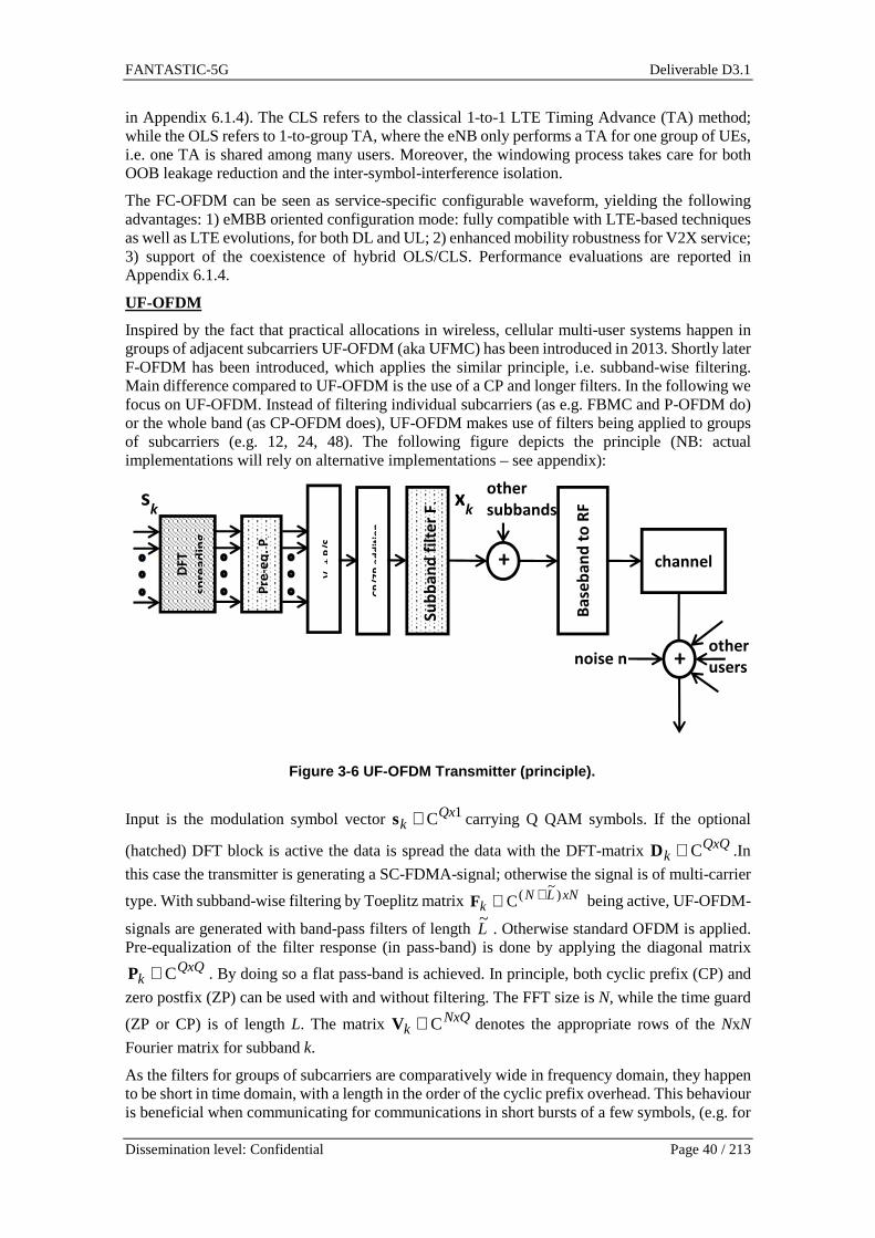
FANTASTIC-5G Deliverable D3.1
Dissemination level: Confidential Page 40 / 213
in Appendix 6.1.4). The CLS refers to the classical 1-to-1 LTE Timing Advance (TA) method; while the OLS refers to 1-to-group TA, where the eNB only performs a TA for one group of UEs, i.e. one TA is shared among many users. Moreover, the windowing process takes care for both OOB leakage reduction and the inter-symbol-interference isolation.
The FC-OFDM can be seen as service-specific configurable waveform, yielding the following advantages: 1) eMBB oriented configuration mode: fully compatible with LTE-based techniques as well as LTE evolutions, for both DL and UL; 2) enhanced mobility robustness for V2X service; 3) support of the coexistence of hybrid OLS/CLS. Performance evaluations are reported in Appendix 6.1.4.
UF-OFDM
Inspired by the fact that practical allocations in wireless, cellular multi-user systems happen in groups of adjacent subcarriers UF-OFDM (aka UFMC) has been introduced in 2013. Shortly later F-OFDM has been introduced, which applies the similar principle, i.e. subband-wise filtering. Main difference compared to UF-OFDM is the use of a CP and longer filters. In the following we focus on UF-OFDM. Instead of filtering individual subcarriers (as e.g. FBMC and P-OFDM do) or the whole band (as CP-OFDM does), UF-OFDM makes use of filters being applied to groups of subcarriers (e.g. 12, 24, 48). The following figure depicts the principle (NB: actual implementations will rely on alternative implementations – see appendix):
Input is the modulation symbol vector 1CQxk ∈s carrying Q QAM symbols. If the optional
(hatched) DFT block is active the data is spread the data with the DFT-matrix QxQk C∈D .In
this case the transmitter is generating a SC-FDMA-signal; otherwise the signal is of multi-carrier
type. With subband-wise filtering by Toeplitz matrix xNLNk
)~
(C +∈F being active, UF-OFDM-
signals are generated with band-pass filters of length L~
. Otherwise standard OFDM is applied. Pre-equalization of the filter response (in pass-band) is done by applying the diagonal matrix
QxQk C∈P . By doing so a flat pass-band is achieved. In principle, both cyclic prefix (CP) and
zero postfix (ZP) can be used with and without filtering. The FFT size is N, while the time guard
(ZP or CP) is of length L. The matrix NxQk C∈V denotes the appropriate rows of the NxN
Fourier matrix for subband k.
As the filters for groups of subcarriers are comparatively wide in frequency domain, they happen to be short in time domain, with a length in the order of the cyclic prefix overhead. This behaviour is beneficial when communicating for communications in short bursts of a few symbols, (e.g. for
VK +
P/S
Su
bb
an
d f
ilte
r Fk
Ba
seb
an
d t
o R
F channel
noise n
other users
sk x
k
DF
T
spre
ad
ing
CP
/ZP
ad
dit
ion
+
Pre
-eq
. Pk
+
other subbands
Figure 3-6 UF-OFDM Transmitter (principle).
FANTASTIC-5G Deliverable D3.1
Dissemination level: Confidential Page 41 / 213
with short TTIs to meet low latency targets). By subband-wise filtering adjacent allocations are isolated - e.g. being transmitted from different mobile devices within a given cell. This isolation reduces the amount of inter-carrier interference being generated in case of:
- adjacent allocations being only loosely synchronized to a common base and thus to each other [SW14], e.g. due to low-end devices skipping the TA procedure as applied in LTE
- adjacent allocations using different numerologies [SWA16], e.g. to allow for the design of shorter TTIs and to improve the performance in high Doppler scenarios.
In addition, the use of the UF-OFDM is favourable for fragmented spectrum scenarios. The close relation of UF-OFDM to CP-OFDM as e.g. applied in LTE allows 5G to:
- make use of the knowledge base available for CP-OFDM - keep valid design decisions of LTE related to the physical layer to be part of 5G (e.g.
related to multi-antenna schemes) - even have CP-OFDM to coexist with UF-OFDM within a single carrier.
Overall, UF-OFDM allows keeping the advantages of CP-OFDM (e.g. the possibility to apply frequency selective scheduling, use of one-tap equalization, simple applicability of complex precoding mechanisms) while improving some of its characteristics, especially the spectral localization, enabling the air interface of 5G to be highly configurable. This enables the introduction of new services (e.g. from the family of the Internet of Things – i.e. MMC, MCC - and use cases benefiting from broad- and multicast signalling) into future cellular communication systems opening up the ecosystem to new players from vertical industries. The cost to pay for this increased flexibility is a slightly higher sensitivity to delay spread. However, for deployments with intercell-distances up to few kms and with reasonable numerology settings, this impact is negligible. Furthermore, relative to the overall complexity of the baseband processing chain, slightly more effort needs to be spent for modulating the signals. This being said, this increase of complexity (see appendix 6.1.1.1) mainly occurs at the base station. With devices typically modulating only a fraction of the whole band, the increase of complexity is far from being obstructive; efficient look-up table-based transmitter implementations exist, enabling machine-type devices with very low complexity. Naturally, as UF-OFDM is a multi-carrier waveform, PAPR is rather high compared to single-carrier waveforms. However, any mechanism being applicable to CP-OFDM (e.g. DFT-precoding for generating an SC-FDMA variant, clipping, etc.) can be used for UF-OFDM in the same way with the same gains.
In appendix 6.1.1 we have provided a set of results complementing the wide range of publications available on the following areas:
1. Tx and Rx implementations with reduced complexity 2. To what extend UF-OFDM is able to allow the use of different spacings within a single
carrier 3. The effect with allowing specific devices to transmit signals with only coarse
synchronization and impacts to the receiver design 4. The impact of delay spread channels to a system applying UF-OFDM 5. Co-existence capabilities of UF-OFDM with CP-OFDM
Waveform comparison:
A transceiver description and a qualitative overview of the waveform properties are provided in Table 3-1 highlighting their pros and cons as well as the targeted services.
Table 3-1 Pros and Cons of different waveforms.
Waveform Features Pros Cons Targeted service

FANTASTIC-5G Deliverable D3.1
Dissemination level: Confidential Page 42 / 213
UF-OFDM / F-OFDM
OFDM compatible,
low out of band emissions (OoBE) between sub-bands
Sub-band wise configurability,
async. FDMA access support
coexistence with CP-OFDM
Slightly more prone to delay-spread channels
Multi-service
ZT-s-OFDM
DFT spread OFDM (DFTs-OFDM) like, good coexistence capabilities thanks to low OoBE
Coexistence with OFDM,
zero-tail adjustable
Overhead of the zero-tail increases for small bandwidth allocation
MMC
FS-FBMC FBMC-OQAM with large FFT for mod. /demod., simple parameterization
Like FBMC-OQAM + support for large delay spreads & enlarged time offsets for async. access
Not fully OFDM compatible,
long filter tails increase delay for short bursts
Multi-service
QAM-FBMC
different filters for even and odd subcarriers enable the use of QAM �OFDM compatible
Sub-band wise configurability,
async. FDMA access support
Not fully orthogonal
Multi-service
P-OFDM Pulse shaping as free design parameter, OFDM compatible, low OoBE, Cyclic prefix (CP)-like overhead
Sub-band wise configurability,
robustness to time/freq. distortions,
async. access support
Filter length may be limited by delay constraints
Multi-service
FC-OFDM
Multiplexing of diff. waveforms in the transmission band
Coexistence of different waveforms in the same band, inheriting the pros of multiplexed waveforms
Not all the native features of the waveform candidates can be maintained once multiplexed
Multi-service

FANTASTIC-5G Deliverable D3.1
Dissemination level: Confidential Page 43 / 213
3.1.3 Special application of positioning with wavef orms Additionally to the previous requirements, supporting positioning is considered of great value for 5G systems since it can spur further developments of location-based services (LBS). Although GNSS-based solutions are the dominant technology in outdoor scenarios, cellular communication systems have also included mechanisms to enable localization [23.271], either as part of a hybrid solution for seamless outdoor/indoor transition or to assist GNSS receivers. Among the different approaches to enhance positioning through communication networks, taking into account positioning-related requirements in the design of the air interface can provide additional advantages. In particular, a judicious waveform selection and pilot design can enable to compute a distance-related measurement from the signal itself with high accuracy.
Motivation: It is recognized that GNSS, this technology is not reliable indoors as the signals emitted from the satellite constellations are greatly attenuated. Besides, in very challenging outdoor environments, GNSS positioning could be denied due to signal blockage, multipath channels, weak signal, or insufficient visibility. In such situations, one typically uses complementary technologies whose primary purpose was not positioning but communications. These signals are known as signals of opportunity (SoO) [DFM11, DCD+15]. However, since these signals were not initially conceived for positioning purposes, their accuracy is typically low when compared to GNSS technology.
Solution: There are various ways in which communication systems could be used to enable positioning. For instance, LTE has a dedicated protocol to provide assistance data to GNSS receivers, which can be used for instance to boost its time to acquire [Dig09]. Another approach is to use the signal itself to compute a distance-related measurement (such as time-of-arrival) and solve the geometrical problem to compute the user’s position. We follow this approach by evaluating the ranging performance of candidate waveforms. These signals are typically designed to maximize communication metrics. Hence, their ranging performances are not optimized. For instance, in multicarrier communication systems the optimization of power allocation for capacity achieving transmissions yields to waterfilling solutions, in which more power is assigned to subcarriers with less noise. However, if the optimization is done to maximize the ranging capabilities of the signal, the resulting power allocation tends to assign more power to those subcarriers allocated at the outer sides of the band [ZM08]. We provide an expression for the lower bound of accuracy of a generic multicarrier signal considering the equivalent baseband signal for one symbol [DLS+12],
"#$% = &2()* + ,-.--∈012 exp 67 28$9)* :(3.5.1) where P is the total signal power, Nc the number of subcarriers, 0?* is the set of Nsc pilot subcarriers used in ranging, dk are the symbols and fsc the subcarrier spacing. Each subcarrier has a relative weight pk that satisfies∑ ,-A = )*-∈012 . Assuming this signal model, the theoretical lower bound for estimating its time-delay B is given by the CRB [Kay93]
CDE(B) ≥ HIJ(B) = K?*LA88AN)I∑ ,-A9A-∈012 ,(3.5.2) with SNR=Es/(N0Nc). Clearly from (3.5.2), if more power is allocated to the more extreme subcarriers, the CRB decreases. Also, it appears intuitively that the smaller the symbol period the better in terms of timing recovery. Compared to OFDM, where the symbol period (Ts) is the inverse of the subcarrier spacing Ts = 1/fsc, in FBMC/OQAM the symbol period (which refers to the period of the PAM symbols) is Ts /2, for the same subcarrier spacing. Additionally, OFDM involves complex symbols while in FBMC/OQAM symbols are either real or purely imaginary. Based on the analytical expression for CRB the project has explored the ranging (consequently positioning) capabilities of various signals involved in some of the scenarios and services considered in the project. Details of the numerical evaluation are provided in the Appendix 6.1.6.

FANTASTIC-5G Deliverable D3.1
Dissemination level: Confidential Page 44 / 213
Conclusion: Increasing the total bandwidth improves the overall ranging capabilities as the number of effective subcarriers increases as well. However, the allocation of subcarriers for ranging purposes plays an important role. Numerical evaluation confirms that when allocating subcarriers for ranging purposes it is desirable to place them at the outer sides of the frequency band. Furthermore, results indicate that when placing ranging subcarriers at the outer bands a much lower percentage of subcarriers are sufficient to achieve good positioning compared to random allocation across the band, improving the spectral efficiency of the system. Additionally, since subcarrier spacing has an impact on symbol period, delay estimation benefits from higher subcarrier spacing. In that respect, FBMC/OQAM offers an advantage with respect to other candidate waveforms for which Ts = 1/fsc. We remark that other waveform candidate can also be used for positioning purposes.
3.2 Channel coding and advanced AMC
3.2.1 Motivation FANTASTIC-5G aims at developing a new multi-service Air Interface (AI) for below 6 GHz through a modular design. Therefore, the proposed technical AI components should provide efficient solutions to address the new challenges envisioned in 5G networks, i.e., stringent reliability and latency constraints (for Mission Critical Communications, MCC), short packet messages with sporadic traffic (for Massive Machine Communications, MMC) and increased user data rate for Mobile BroadBand (MBB) services. Unfortunately, the Forward Error Correction (FEC) coding and modulation components of LTE/LTE-A are not optimum in these respects, as they were not designed to meet such requirements. Indeed, the error rate performance for short frame sizes on one side and for high coding rates on the other side represent two main possible study items for a future radio interface. Therefore, this section presents some technical proposals to address the current weaknesses of LTE/LTE-A coding and modulation mechanism and to meet the requirements of 5G networks for the above-mentioned services.
The first contribution of this section proposes some improvements and evolutions for the LTE/LTE-A Turbo Code (TC) to make it able to cope with the new 5G requirements. The second contribution focuses on FEC coding for the MMC and MCC use cases where mainly short packet messages are transmitted. In the next subsection, these coding contributions are enriched by the proposal of a modified modulation scheme, called FQAM, intended to increase the throughput of cell-edge users. Finally, the last contribution deals with the use of link adaptation algorithms with Adaptive Coding and Modulation (ACM). It mainly studies the effect of the relaxation of the orthogonality properties of multicarrier schemes and the integration of multiple antenna and non-binary schemes in the link adaptation procedures.
3.2.2 Design of enhanced Turbo Codes for 5G The conventional FEC coding component of LTE/LTE-A is not designed to answer favorably to service requirements with stringent reliability and latency constraints. A known issue for the LTE TC resides in its poor performance at low error rates when transmitting data with coding rates higher than 1/3. This is due to the well-known “error floor” effect, which can be observed when the TC is punctured with the rate matching mechanism [CNB+08]. A detrimental effect results in the frequent resort to retransmissions through the HARQ mechanism. Moreover, these codes were not originally designed targeting best short packet performance. Therefore, the LTE TC has to be improved to be able to cope with the new requirements introduced by 5G scenarios.
The LTE FEC code introduces tail bits for trellis termination leading to the following drawbacks: First, this results in a non-negligible bandwidth efficiency reduction for short frames. Second, this type of trellis termination introduces low-weight truncated codewords and does not ensure the same protection for all information bits, since tail bits are not encoded twice (i.e., turbo encoded) as regular information bits. We propose to replace tail bits by tail-biting termination [WBR01].

FANTASTIC-5G Deliverable D3.1
Dissemination level: Confidential Page 45 / 213
With this technique, the trellis diagram associated to each component convolutional code is made circular. In other words, the encoder states at the beginning and at the end of the encoding process are always identical, whatever the contents of the input message. This technique has numerous advantages: since no tail bits have to be introduced, there is no code rate loss. Moreover, as all information symbols are turbo encoded, they are all protected in the same way by the code. Furthermore, since the code trellises are made circular, there are no longer truncated codewords due the termination process. Last but not least, circular trellises make the implementation of parallel turbo decoding easier using several component decoders.
The current LTE rate matching module could lead to bad interactions between puncturing and interleaving in the turbo encoder structure, entailing early error floors in the error rate curve as shown in [CNB+08]. Indeed, the rate matcher was originally designed for the sole purpose of avoiding catastrophic puncturing patterns. These latter correspond to the cases where only a Hamming distance of 1 (or only one bit difference) is observed between at least two possible codewords due to puncturing. Therefore, one bit error can cause a large number of bit errors in the code (since a different codeword can be selected instead of the transmitted one). The resulting performance does not show the full potential of an optimized joint design of puncturing and interleaving. In practice, this target is not stringent enough to achieve low error rates with the punctured LTE TC. This problem can be addressed in a number of ways. Possible techniques involve appending a precoder or a post encoder to the existing TC, in order to improve its performance, especially at low error rates [TZB11][BGO+09]. Another option involves jointly designing and optimizing a new TC interleaver and puncturing/rate matching mechanism in order to avoid bad interactions between them. Figure 3-7 shows the performance comparison of several enhanced turbo codes.
Figure 3-7 Frame error rate performance in AWGN cha nnel with BPSK modulation of
1) the original LTE code (LTE), 2) a tail-biting tu rbo code (TBTC) using Almost Regular Permutation [BSD+04] (ARP), 3) a precoded TBTC usi ng ARP (PTC), 4) a TBTC with
optimized puncturing and ARP interleaver (OPI). Block size K = 1504 and coding rate R = 4/5 (RV0 mode, no HARQ).
In further studies, new turbo coding schemes will be considered, based for example on non-binary TCs defined on high-order Galois Fields that could present advantages when short frames (a few dozen bits) are considered, typically for MMC and MCC use cases. Non-binary LDPC codes have been widely investigated [DM98][PFD08] and are described in section 6.2.3. Similar studies have recently started to emerge on the turbo coding side [LPS+11][LPM+13]. As for their LDPC counterparts, non-binary turbo codes show very good performance for short packet lengths.
2.00 2.25 2.50 2.75 3.00 3.25 3.50 3.75 4.00 4.25 4.5010-8
10-7
10-6
10-5
10-4
10-3
10-2
10-1
100
LTE TBTC PTC OPI
FE
R
Eb/N
0 (dB)
FANTASTIC-5G Deliverable D3.1
Dissemination level: Confidential Page 46 / 213
Belonging to the same code family as 3G and 4G FEC codes, they are good candidates for 5G. From the decoding point of view, non-binary decoding faces to the same complexity issue as non-binary LDPC decoding. Then, the search for simplified decoding algorithms and corresponding hardware architectures has still to be investigated.
3.2.3 Link adaptation using NB-LDPC codes Topic motivation:
To meet the stringent throughput and the reliability requirements of 5G networks, the use of link adaptation algorithms with adaptive coding and modulation (ACM) becomes crucial. Consequently, a question arises on whether current solutions will be valid for envisioned new air interfaces. Therefore, attention must be paid to the features that the future air interface might incorporate, e.g. the relaxation of the orthogonality properties of multicarrier schemes and the integration of multiple antenna schemes with new waveform designs. To make progress towards this direction, this section indicates how the link adaptation algorithm can cope with the non-orthogonal effects. As the constituent forward error correcting (FEC) scheme, the adoption of non-binary low density parity check (NB-LDPC) codes are considered. The basics of NB-LDPC are provided in Section 6.2.3. NB-LDPC codes are known to outperform their binary counterpart for low to moderate code lengths [DM98], [PFD08, [LPD12]. Since non-binary codes have shown an inherent advantage in multi-antenna transmission systems [PD10, [PD11], performance differences between non-binary and binary LDPC codes can be even higher in MIMO configurations. Furthermore, NB-LDPC enables a simple repetition coding scheme suitable for integration of ACM with hybrid automatic repeat request (HARQ) retransmissions, which provides additional gain to binary coding repetition and soft combining [KDS12], [PDN14].
Proposed solution:
In order to maximize the throughput and attain the target block error rate (BLER), it is of paramount importance to adapt the transmission to the channel. This boils down to selecting the most spectrally efficient modulation and coding scheme that is able to fulfil the BLER constraints. To achieve a fine-grained control of the spectrum, the air interface relies on multicarrier modulation schemes, which allows working with non-overlapping resource blocks (RBs). As a result, the channel becomes frequency selective. To perform the link adaptation in this scenario, it is proposed to resort to mutual information-based ACM algorithms to select the code rate and the modulation format to be used over the time-frequency grid. It is worth recalling that in the LTE standard, all the RBs allocated to a given codeword have to use the same modulation and coding scheme. By contrast, the proposed algorithm adapts the modulation on a per RB basis to increase the throughput. The excellent trade-off between complexity and performance shown for OFDM waveforms motivates the selection of the modulation and coding schemes according to the algorithm presented in [SBC07]. The suitability and applicability of the algorithm under non-orthogonal waveforms design have been evaluated. When the multicarrier modulation is orthogonal, such as OFDM, the selection is ultimately dictated by the SNR of each RB. However, other multicarrier schemes relax orthogonality properties to improve the spectral confinement. In this case, the SNR is replaced with the SINR, which depends on the modulation-induced interference, also known as self-interference or intrinsic interference. If all sources of distortion are characterized, the algorithm can be straightforwardly applied to different air interfaces, even if orthogonality is not preserved. Using the closed-form expressions provided in [MMP13], the work presented in [CNM+16] shows how the ACM described in [SBC07] can be tailored to the filter bank multicarrier modulation based on OQAM (FBMC/OQAM) [SSL02]. The proposed link adaptation algorithm is further detailed in Section 6.2.5.
It is important to remark that the noise is highly likely to be colored when orthogonality is not satisfied. Then, the mapping scheme, which determines how the symbols are transmitted in the time-frequency grid, can be optimized to minimize the correlation of the noise and simplify the soft-demapping. In MIMO configurations the challenges are intensified, owing to the fact that multiple streams are simultaneously transmitted on each time-frequency resource element. The

FANTASTIC-5G Deliverable D3.1
Dissemination level: Confidential Page 47 / 213
issues related to the mapping in SISO and MIMO communication systems are addressed in Section 6.2.4.
Concerning the code, it is suggested to leverage on ultra-sparse NB-LPDC codes [PFD98]. The field order has been set to 256 and the message length is 90. Building upon the mother code of rate 1/2, a wide range of code rates can be obtained by puncturing and non-binary repetition. The code rates and its performance curves used for link adaptation are included in Section 6.2.3.
3.2.4 Low-Latency channel coding In general, channel encoders and decoders work block-wise, i.e., for encoding and decoding the complete sequence has to be available at the input, which inherently causes a delay. One way to reduce this delay is to divide the messages into smaller parts and encode them separately; however the choice of the channel code becomes critical as the error correction performance degrades with decreased message lengths. In this section, we evaluate the error correction performance of some important classes of channel codes for message lengths k ≤ 512 bits.
Figure 3-8 Performance of different channel codes o f different lengths in terms of
required SNR to achieve a target packet error rate 0.001.
For short message lengths, Shannon’s capacity bound becomes less accurate for evaluating the error correction performance, as it relies on the infinite length assumption. Moreover, in practical scenarios one often does not need a vanishing error probability (as it is the case for Shannon’s capacity formula), and achieving a target non-zero error probability (according to the requirements of the application) is mostly enough. Therefore, for the performance evaluation finite block length bounds are more suitable. Recently, Polyanskiy et.al provided tight bounds of channel coding rate for finite block lengths and for given error probability [PPV10]. Figure 3-8 depicts the the performance of different channel codes of rate ½ on an AWGN channel with BPSK modulation in terms of Eb/N0 in dB required to achieve a target block error probability 0.001 for different message lengths k(different markers), Gaussian approximation of the Polyanskiy finite length bound for BPSK [PPV10] (dashed line) and BPSK constrained capacity (solid line). The parity streams of LTE Turbo code are punctured uniformly to obtain the target code rate, and the decoding is performed with 10 iterations under LogMap decoding. LTE Tailbiting Convolutional Codes (TBCC) are decoded using Viterbi algorithm. Polar+CRC codes are designed numerically by using density evolution to select the set of frozen bits, and are decoded with a list decoder of list size L=32 and L=1024; CRC of length 8 is used for k≤128 and CRC of length 16 is used for longer codes. NB-LDPC codes are designed to be regular with variable-node degree 2, check-node degree 4, and the coefficients of the parity check matrix are selected randomly from the set of optimized coefficients in [PFD08]. The performance result of eBCH code is taken from [VF04].
0 50 100 150 200 250 300 350 400 450 500
Message Length k [bits]
-1
0
1
2
3
4
5
BPSK Constr. Capacity
Polyanskiy Approx. for BPSK
LTE Turbo Code
LTE TBCC
Polar+CRC L=32
Polar+CRC L=1024
NB-LDPC GF(256)
eBCH OSD

FANTASTIC-5G Deliverable D3.1
Dissemination level: Confidential Page 48 / 213
One observes that the LTE Turbo codes have a gap to the finite length bounds, and by using modern channel coding schemes (like Polar+CRC codes with list decoding or non-binary LDPC codes with non-binary message passing algorithm) the gap to the bounds can be made smaller. This improvement is mainly achieved by allowing a higher computational complexity at the decoder. In fact, one can obtain 1.34 dB gain for k = 64 compared to LTE turbo, if an ordered statistics decoding (OSD) is used with an extended BCH code, which has a much higher complexity and is not feasible for longer codewords.
We observe that for coding in short block length regime, the main performance improvement is obtained by using advanced decoders. OSD and Polar List decoders can be seen as approximations of Maximum-Likelihood (ML) decoders, as they try to find the best codeword from a limited set. The reason why NB-LDPC decoders perform well is also similar: unlike binary codes, the variable nodes represent a block of bits, and as the field size increases, larger blocks of bits are updated jointly, which improves the performance. One can also conclude that, LTE turbo code with iterative decoding is not well suited for short block length communication, since it does not perform as good as in the moderate and long block length regime. By allowing higher decoding complexity, one can obtain more coding gain for short message transmissions with advanced channel codes/decoders.
3.2.5 Frequency quadrature amplitude modulation In the conventional QAM modulation that is adopted in LTE, data symbols are transmitted on all the subcarriers that are assigned for data transmission in the resource block. On the other hand, frequency quadrature amplitude modulation (FQAM) represents a combination of frequency shift keying (FSK) and QAM, where information bits are conveyed by selecting one active subcarrier among a subset of candidates and modulating the selected subcarrier with a QAM symbol [HSL+14]. M-ary FQAM carries Q = log2(M) information bits by selecting one subcarrier among MF subcarriers and modulating the selected subcarrier with an MQ-ary QAM constellation. Hence, the modulation order of the resulting FQAM symbol is given by M = MFMQ. An example is shown in Figure 3-9 for MF= 4 subcarriers and MQ = 4 QAM constellation. The motivation for FQAM is coming from the fact that the worst-case distribution of additive noise in terms of channel capacity is the Gaussian distribution [SA13]. Having some of the subcarriers inactive in FQAM results in inter-cell interference with non-Gaussian distribution, which will improve the achievable spectral efficiency. This advantage is most prominent in interference limited scenarios, such as at cell-edge where the inter-cell interference is the dominant factor. Detailed interference analysis for FQAM with comparison to QAM modulation is presented in [FAN-D41]. The analysis has shown that even with dense small-cells deployment, FQAM keeps the non-Gaussian distribution feature of inter-cell interference. The cell-edge users’ throughput can be significantly improved using FQAM, as shown in [HSL+14] and Section 6.2.2 of the Appendix. From the performance evaluation presented here and in [HSL+14], one can conclude the FQAM represents a promising modulation technique to enhance the system performance in heavy interference environment.
Figure 3-9 FQAM example with MF = 4 subcarriers and MQ = 4 QAM constellation.

FANTASTIC-5G Deliverable D3.1
Dissemination level: Confidential Page 49 / 213
3.2.6 Conclusion For MBB core services, 5G will have to support mobile broadband connections with increased capacity, efficiency and data transmission rates. The error floor issue of the current LTE/LTE-A turbo code when punctured using the rate matching mechanism is not compatible with the requested increased user data rate, since high coding rates are then required. Nor is it for BMS where retransmissions are not allowed. This issue can be addressed by: 1) slightly modifying the current LTE/LTE-A TC in order to make the trellises of its component codes circular using tail-biting technique; 2a) jointly designing the code interleaver and puncturing patterns with incremental redundancy support or 2b) introducing a precoder in front of the original LTE turbo code, leading to a “turbo-like” code structure that can have common encoding/decoding blocks with LTE encoder/decoder.
MMC core services, as well as MCC core services, require channel codes suited for short packet sporadic traffic. Unfortunately, LTE turbo code performs far from the theoretical bounds for block lengths of a few dozen bits to a few hundred bits. Promising alternatives to the LTE code are non-binary FEC codes defined on high-order Galois Fields. Non-binary codes from the LDPC (see Section 6.2.3) and turbo families, have been shown to perform better than their binary counterparts for short frames, especially when used in non-binary transmission channels and/or with MIMO. The association of polar codes with a CRC code with list decoding can also be considered for these services.
Additionally to enhanced FEC coding, modulating the signal with FQAM, a combination of FSK and QAM modulations, proves to enhance the system performance in heavy interference environment and provides an efficient means for increasing the throughput of cell-edge users.
Having defined the channel coding scheme and the modulation family, the coding rate and the modulation order has to be carefully selected taking into account the changing propagation conditions, in order to ensure reliable packet delivery with a pre-defined quality of service. In the advent of transceivers able to implement link adaptation with ACM that benefit from pulse shaping techniques, it is deemed necessary to take into account the characteristics of the waveform, e.g. the time-frequency lattice structure and the non-orthogonal effects. In this sense, the channel quality indicator has to include all the sources of distortion. Bearing this in mind, the algorithm proposed in Section 6.2.5 is sufficiently general to accommodate different multicarrier schemes. The corresponding numerical results were obtained with NB-LDPC channel codes and FBMC/OQAM waveform. This modulation does not inherit the kernel of OFDM. Therefore, the application of ACM to FBMC/OQAM represents the major challenge. In this regard, the performed work experimentally verifies that the integration is feasible in SISO and MIMO communication systems. Simulation-based results corroborate that ACM is the best strategy to provide the highest throughput in the whole SNR range, subject to BLER constraints. However, the numerical results also reveal that competitive results can be achieved in a wide range of SNR values, by fixing the modulation across the RBs when the NB-LDPC codes introduced in Section 6.2.3 are applied. Nevertheless, this conclusion cannot be generalized for any code rate, so that non negligible differences may appear in other modulation and coding schemes.
3.3 Low PAPR design
3.3.1 Motivation PAPR is an important factor in the design of air interface for future communication systems. Generally, a high PAPR requires highly linear power amplifiers (expensive) or a large input back-off (energy inefficient) in order to protect the signal from severe degradation due to the non-linearity. Hence, the idea of PAPR reduction schemes was proposed in the literature in order to combat this problem without the loss in power efficiency.

FANTASTIC-5G Deliverable D3.1
Dissemination level: Confidential Page 50 / 213
In the current LTE uplink transmission, single carrier based DFTs-OFDM is used. The PAPR of DFTs-OFDM is usually lower than multicarrier transmission. However, compared with multi-carrier transmissions in frequency-selective channel, DFTs-OFDM, which is essentially a single-carrier based transmission, is more sensitive to the channel distortion. In addition, the MIMO support like sphere detector is challenging for DFTs-OFDM due to high complexity [GAA+12]. Along the lines of thought, herein the target is not solely the reduction of PAPR, but rather considering and compromising the PAPR and link performance together to design a proper transmission schemes, e.g., whether a single-carrier or a multi-carrier based transmission is suitable.
3.3.2 Proposed solutions Low PAPR Design for OFDM – based Multicarrier Concerning pulse shaped OFDM technique as an example of multi-carrier scheme, the PAPR level of P-OFDM is comparable to the one of CP-OFDM and higher than DFTs-OFDM. There are three standard approaches for Low PAPR design of P-OFDM systems. Firstly, we can design the multi-carrier systems by adapting the subcarrier spacing according to channel frequency selectivity and PAPR target (as this measure scales with number of subcarriers). Secondly, the idea of transforming into a single-carrier transmission can be applied to pulse shaped OFDM, similar to DFT-spread OFDM systems. Thirdly, for constrained modulation order, signal clipping approach is considered as a simple and efficient method to reduce the PAPR level. Although this measure induces a signal error vector magnitude (EVM) loss, it only introduces marginal link performance loss, as long as the EVM is kept in limits to still facilitate a reliable transmission. In Section 6.3.2 a detailed performance comparison of DFTs-OFDM, OFDM, and P-OFDM is provided regarding PAPR and link performance for different propagation channels.
Low PAPR Design for FBMC Regarding FBMC–based systems, two new schemes for PAPR reduction are investigated. The first is a general scheme that is applicable to any multicarrier modulation technique. The second is a modification of one of the schemes that were proposed for OFDM to benefit from the special structure of the FBMC/OQAM time signal as depicted in Figure 3-10 and hence have additional gains in PAPR reduction.
Figure 3-10 FBMC/OQAM vs. CP-OFDM signal structure.

FANTASTIC-5G Deliverable D3.1
Dissemination level: Confidential Page 51 / 213
The first, two-stage PAPR Reduction is a newly proposed set of PAPR reduction schemes, whereas, evident from the naming, the reduction is done in two separate stages. The first stage consists in applying one of the iterative clipping based schemes (i.e., TR, ACE, TRACE); clipping is the second (and final) stage. This means that it is a version of the iterative schemes, where after the predefined maximum number of iterations is reached a further clipping is applied giving the final output.
Modified Selected Mapping: It is quite appealing to take the overlapping of the FBMC/OQAM time symbols into consideration for PAPR reduction and thus have an additional gain. Thus, we have devised a new scheme that we called “modified SLM (mSLM)” similar to the scheme proposed in [HH11] for wavelet OFDM. This scheme considers OP hypotheses instead of justOas for the regular SLM, and hence a great increase in computational complexity is expected, as well as a larger gain in PAPR reduction [ED16]. In Section 6.3.1, a detailed performance comparison of the proposed solutions is provided.
For the FBMC case, it is shown that exploiting symbol structure in the time domain reduces the PAPR compared to SLM and does not deteriorate the signal. However, the PAPR reduction performance of mSLM increases with U increases to the cost of increased computational complexity, since URhypotheses have to be considered instead of just U for regular SLM. Table 3-2 qualitatively summarizes the newly proposed schemes comparing them in terms of symbol error rate (SER) performance, effect on the transmission power, added overhead and transmitter complexity.
Table 3-2 PAPR reduction techniques for FBMC.
Technique/Criteria Degrade SER Increased Power
Overhead Complexity
Two-stage � �/- (depends on first stage)
�/- (depends on first stage)
+++
mSLM - - �/- ++++
3.3.3 Conclusion Low PAPR is not the sole target we are aiming at in the system design. In order to choose between the single-carrier and the multi-carrier based scheme, other aspects need to be taken into consideration, such as link-level energy efficiency including the PAPR, power amplify back-off, as well as link performance for different channels and scenarios.
3.4 MIMO techniques for new waveforms
In this section several MIMO techniques are addressed, more or less specific to the waveform they are design upon. The section 3.4.1 presents a way to leverage MIMO to perform multiple access, and is quite generic; Section 3.4.2 is dedicated to FBMC and proposes an Alamouti-like scheme; Section 3.4.3 proposes a MIMO scheme adapted to P-OFDM. Finally, Section 3.4.4 proposes to anticipate the move of the mobile to benefit from better beamforming, thus exploiting MIMO.
3.4.1 Enhanced spatial modulation Motivation: Multiple-input multiple-output (MIMO) technologies are now commonly used in wireless communications systems to improve throughput, coverage, or both. The main limitation of MIMO systems in practice is related to their implementation complexity, which increases linearly with the number of antennas [TSE2005]. A class of MIMO schemes, which is known as

FANTASTIC-5G Deliverable D3.1
Dissemination level: Confidential Page 52 / 213
Spatial Modulation (SM), was introduced for wireless systems in which the number of RF chains in the transmitter is smaller than the number of antennas [MSL+09] [RENZ2011], [MG11]. Since the number of RF chains is restricted, all antennas cannot be active simultaneously. The basic principle of SM consists of selecting the indexes of the active antennas using information bits. Additional information bits are transmitted through the symbols transmitted from the active antennas. Since all transmit antennas are not active at the same time, SM suffers from limited throughput compared to spatial multiplexing (SMX), which transmits symbols in parallel from all of the antennas. In order to increase the throughput, we recently introduced an enhanced spatial modulation (ESM) scheme that is based on using multiple signal constellations [CSS+15], [CSS+15b]. More specifically, in addition to the primary constellation, these schemes make use of one or more secondary constellations, obtained through geometric interpolation in the signal constellation plane. With the number of antenna/modulation combinations in ESM being higher than the number of active antenna combinations in conventional SM, this technique increases the spectral efficiency. Alternatively, ESM improves system coverage compared to SM when both techniques are used at the same spectral efficiency.
Still, whether in their conventional form or enhanced form, SM techniques provide a limited throughput compared to SMX when The number of RF chains and transmit antennas are the same. In fact, from the perspective of throughput, SMX actually provides the upper limit for all MIMO techniques. The problem of SMX is the limited performance and the high decoder complexity. In our studies, we introduce an enhanced SMX (E-SMX) technique, which provides a signal-to-noise ratio (SNR) gain of several dB compared to conventional SMX.
Proposed solution: This new concept is based on using multiple signal constellations derived through geometric interpolation as in ESM. The detail of the study can be found in [CSS+16]. In this study, we introduce two enhanced SMX schemes that use multiple constellations of reduced size and energy to improve the system performance over conventional SMX. The signal design is made in such a way as to preserve the minimum Euclidean distance in the signal space while reducing the average total transmit energy. Description of the introduced schemes is made for 16, 32, and 64 bits per channel use, but the design principle is general and can be applied to higher spectral efficiencies. The first scheme uses two constellations and provides an SNR gain up to 2.2 dB, while the second scheme uses four constellations and provides an SNR gain up to 5.2 dB. Performance evaluation of the proposed E-SMX schemes was made using Monte-Carlo simulations on Rayleigh fading channels assuming perfect channel state information. The results showed that, as predicted by the theoretical results, the proposed schemes achieve significant performance gains compared to conventional SMX.
3.4.2 Alamouti scheme for FBMC Motivation: The fact that the FBMC-OQAM modulation is not orthogonal in the complex domain makes the combination of FBMC waveforms and MIMO schemes not straightforward. In particular, the direct application of the well-known Alamouti coding scheme [AL98] is not possible; the intrinsic interference indeed breaks the orthogonality expected with Alamouti coding.
In [RIS10], a block-wise Alamouti scheme is proposed. The orthogonality of the Alamouti coded frame is preserved by sending the conjugate time reverse block. In the basic scheme, guard times are inserted between the Alamouti coded frames to manage the interference. The performance of the block-wise Alamouti scheme combined with a PPN (poly phase network) based receiver is quite good in case of stationary channel with small frequency selectivity.
Based on early results of [DBC+14], we propose to investigate how the block-wise Alamouti scheme and the receiver proposed in [DBC+14] (called Frequency-Spreading FBMC receiver) can be adapted to improve performance in case of channel with high frequency selectivity.
Proposed solution: The main idea of the block-wise time reversal Alamouti scheme for FS-FBMC receiver is to combine the two received blocks after the FFT and before the filtering process (see Figure 3-11). This strategy will give better performance when the frequency

FANTASTIC-5G Deliverable D3.1
Dissemination level: Confidential Page 53 / 213
selectivity of the channel increases. The difference between the PPN receiver and the proposed one stems from, first, the structure of the equalizer, and secondly, from the correction factor necessary to guarantee the orthogonality in case of FS-FBMC base receiver (see Appendix 6.4.1 for more details).
In the proposed scheme, guard periods should be inserted to maintain the symmetry required by the Alamouti block-wise scheme. In case of burst transmission with a preamble, it is possible to relax this constraint. Indeed, when a preamble is transmitted, the receiver knows exactly the sequence and therefore the interference generated on payload symbol. If the channel is perfectly known a simple interference cancellation scheme is sufficient to maintain the symmetry required by the Alamouti block-wise scheme.
The block diagram of the corresponding receiver including the interference cancellation (IC) block is depicted in Figure 3-11, where “TR+*” stands for time reversal (combined with conjugate operator) ; this block models a Last Input First Output (LIFO) queue.
Figure 3-11 Proposed receiver based on FS-FBMC stra tegy with preamble interference
cancellation (2x1 configuration).
We propose to compare the two receivers’ architectures for various sizes of FFT from 16 to 256. By increasing the FFT size (decreasing the intercarrier spacing), the selectivity of the channel is decreased. The Mean Square Error (MSE) on received QAM symbols is estimated using Monte-Carlo simulations. No noise is added to the signal and a perfect knowledge of the channel coefficients is assumed. Coded blocks are spaced/separated by a block of null samples to ensure the perfect orthogonality. The performances are depicted in Figure 3-12.

FANTASTIC-5G Deliverable D3.1
Dissemination level: Confidential Page 54 / 213
Figure 3-12 Comparison of two receiver strategies a s a function of the FFT size.
The results clearly demonstrate the advantage of the receiver based on FS-FBMC principle. When the ratio of channel delay spread over the FFT size decreases, the performance of a PPN receiver tends to the one of the proposed receiver. On the contrary if this ratio is small, the performances of the PPN receiver are quite bad. FS-FBMC based receiver keeps good performance even with a "large" ratio of channel delay spread over the FFT size. This result has also been demonstrated for single input single output (SISO) channel in [DBC+14]. More details on the proposed scheme are given in the appendix 6.4.1.
Conclusion: We have derived an Alamouti scheme compatible with FS-FBMC receiver. The proposed scheme works with block of symbols and requires guard time between blocks to guarantee the “Alamouti” orthogonality. We have demonstrated the benefits of the proposed scheme combined with FS receivers, especially when the inter-carrier spacing is large (small size of FFT). Increasing the inter-carrier spacing allows lowering the size of the FFT that also reduces the complexity and the number of simultaneous active carriers. This point has a direct impact on the PAPR that is also decreased. This makes the proposed scheme particularly relevant for MCC scenarios, in which, power consumption, complexity and robustness are key parameters.
3.4.3 MIMO compatibility for P-OFDM Motivation: MIMO compatibility is considered as a desired characteristics for the waveform selection in 5G. Here we show that the complex orthogonality condition is fulfilled for the proposed pulse shaped OFDM systems, enabling a straightforward application to MIMO channels, and intuitively also supporting all MIMO modes from LTE/LTE-A.
Solution: The application of P-OFDM in MIMO scenarios is addressed with the focus on the transceiver structure, reference signal design, and the receiver algorithms. The performance is evaluated and compared with conventional OFDM systems.

FANTASTIC-5G Deliverable D3.1
Dissemination level: Confidential Page 55 / 213
Figure 3-13 Transceiver block diagram of P-OFDM sys tems
Figure 3-13 depicts the transceiver structure of P-OFDM applied to MIMO Bit-Interleaved Coded Modulation (BICM) systems. Some important explanations regarding the transceiver procedure are introduced as follows. Specifically, at the transmitter side, the coded bits are generated by encoding the information bits with certain type of error correction coding and then are passed to the bitwise interleaver. Afterwards, transmit symbols are generated based on the interleaved coded bits, which are then de-multiplexed into )S data streams/layers via the precoding. The precoding matrix is adjusted for different MIMO techniques, (spatial multiplexing, transmit diversity, etc.). In the next step, the precoded complex-valued symbols for each antenna port are mapped to physical resource elements. For the purpose of a fair comparison, LTE-compatible resource mapping design is applied to both P-OFDM and CP-OFDM systems. At the receiver side, the demodulator uses the received vector and the channel matrix to calculate log-likelihood ratios (LLRs) for all coded bits, which are indicated by the complex-valued soft symbols after symbol demapping. Such LLRs are passed through the deinterleaver and then to the channel decoder that delivers the detected bits. In Appendix 6.4.2, our performance has shown that P-OFDM can achieve the same performance as CP-OFDM for all LTE MIMO transmission modes
Conclusion: Pulse shaped OFDM is fully compatible with all MIMO modes in LTE/LTE-A and supports MIMO techniques like conventional CP-OFDM.
3.4.4 MIMO for vehicular communications Motivation: In the future, we expect 5G networks to handle masses of Infrastructure-to-vehicle (I2V) links with a target quality of service (QoS), such as an initial target BLER of 10%, and a target rate. Unfortunately, when the connected vehicle is moving, due to the ‘channel aging effect’, the network cannot save power and spectrum by using maximum ratio transmission (MRT) MISO beamforming and Zero Forcing (ZF) MIMO, respectively. Instead, at high velocity, a QoS mechanism triggers a fall back to a scheme which is robust to speed but not efficient in term of power and spectrum usage, such as receive diversity (RD). In this case, to maintain the target QoS, the system must spend more power and spectrum.
Solution: We study solutions to guarantee a target QoS (a target rate with a target initial BLER of 10%). As a reference, we consider an RD system with 5 receive antennas. A transmit power margin (determined empirically) is used, that ensures the QoS is met for all speeds up to 300km/h. On one hand we study the power consumption of maximum ratio transmission (MRT) MISO with various channel prediction schemes [PSS15]: the ‘Separate Receive and Training Antenna’ (SRTA) prediction scheme (based on the ‘predictor antenna concept’ and illustrated by Figure 3-14-b), no prediction (we call this scheme the “Reference System” (RS) and illustrate it by Figure 3-14-a) and perfect prediction (PP)). For any scheme, based on an empirical knowledge of the performance of the considered scheme versus speed, a QoS mechanism adapts the number of transmit antennas (up to 256) to the speed, to guarantee the QoS. If the QoS cannot be guaranteed with MRT-MISO, the QoS mechanism falls back to RD. For each considered scheme, the resulting power consumption (at the network side) is computed. In a second step, ZF-MIMO with SRTA (illustrated by Figure 3-14-d), RS (illustrated by Figure 3-14-c) and perfect prediction
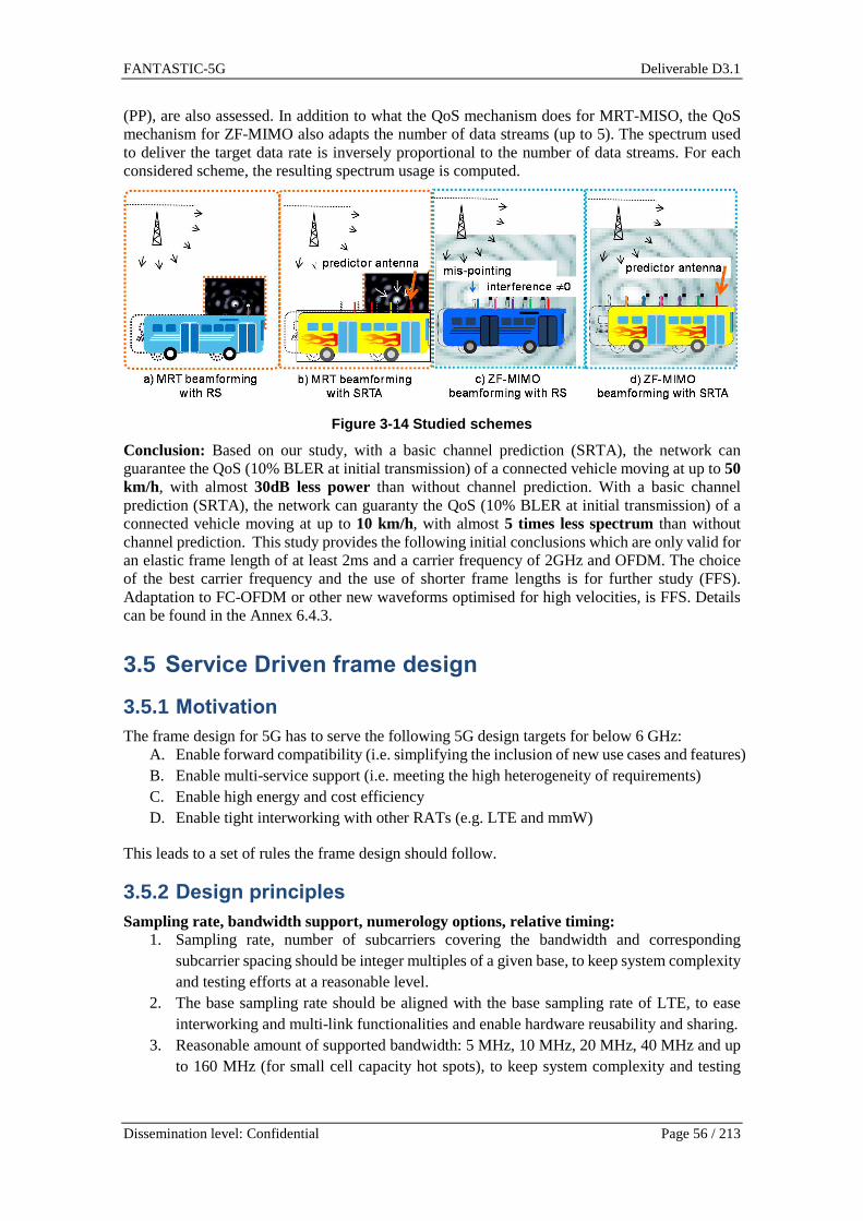
FANTASTIC-5G Deliverable D3.1
Dissemination level: Confidential Page 56 / 213
(PP), are also assessed. In addition to what the QoS mechanism does for MRT-MISO, the QoS mechanism for ZF-MIMO also adapts the number of data streams (up to 5). The spectrum used to deliver the target data rate is inversely proportional to the number of data streams. For each considered scheme, the resulting spectrum usage is computed.
Figure 3-14 Studied schemes
Conclusion: Based on our study, with a basic channel prediction (SRTA), the network can guarantee the QoS (10% BLER at initial transmission) of a connected vehicle moving at up to 50 km/h, with almost 30dB less power than without channel prediction. With a basic channel prediction (SRTA), the network can guaranty the QoS (10% BLER at initial transmission) of a connected vehicle moving at up to 10 km/h, with almost 5 times less spectrum than without channel prediction. This study provides the following initial conclusions which are only valid for an elastic frame length of at least 2ms and a carrier frequency of 2GHz and OFDM. The choice of the best carrier frequency and the use of shorter frame lengths is for further study (FFS). Adaptation to FC-OFDM or other new waveforms optimised for high velocities, is FFS. Details can be found in the Annex 6.4.3.
3.5 Service Driven frame design
3.5.1 Motivation The frame design for 5G has to serve the following 5G design targets for below 6 GHz:
A. Enable forward compatibility (i.e. simplifying the inclusion of new use cases and features) B. Enable multi-service support (i.e. meeting the high heterogeneity of requirements) C. Enable high energy and cost efficiency D. Enable tight interworking with other RATs (e.g. LTE and mmW)
This leads to a set of rules the frame design should follow.
3.5.2 Design principles Sampling rate, bandwidth support, numerology options, relative timing:
1. Sampling rate, number of subcarriers covering the bandwidth and corresponding subcarrier spacing should be integer multiples of a given base, to keep system complexity and testing efforts at a reasonable level.
2. The base sampling rate should be aligned with the base sampling rate of LTE, to ease interworking and multi-link functionalities and enable hardware reusability and sharing.
3. Reasonable amount of supported bandwidth: 5 MHz, 10 MHz, 20 MHz, 40 MHz and up to 160 MHz (for small cell capacity hot spots), to keep system complexity and testing

FANTASTIC-5G Deliverable D3.1
Dissemination level: Confidential Page 57 / 213
efforts at a reasonable level, while supporting all reasonable scenarios. Smaller bandwidth options might be envisaged in later standard releases.
4. Means to support narrow-band devices by dedicated design of in-band structures are required (e.g. introduction of complementary narrow-band synchronization signals), to successfully integrate MMC services while still enabling MMC devices to be low-cost and long-lasting with a single set of energy sources.
5. The basic 5G subframe length should follow LTE (i.e. have a duration of 1 ms), to ease interworking and multi-link functionalities and enable hardware reusability and sharing. To enable low latency transmissions, special subframes with lengths being fractions x of 1 ms should be supported (e.g. x=2N with Integer N, e.g. N = [0, 1, 2, …]).
6. Subframe bundling needs to be supported (for longer transmission opportunities), to increase the signalling efficiency (less control signalling required) and to support coverage extension.
7. The support of different subcarrier spacings (following rule 1) within a single carrier should be envisaged, to improve respective use cases (e.g. low latency transmissions) and transmissions with extreme channel characteristics (e.g. very high Doppler values), while maximizing multiplexing gains and reducing the number of constraints for e.g. scheduling.
8. Transmission points are aligned to a common base, to ease collaborative schemes such as interference coordination.
Lean channel/signal design, time/frequency confined structures, access procedures: 1. Use of multi-carrier signalling, to allow for simple transceiver mechanisms (e.g. one-tap
equalization, frequency selective precoding) and multiple transmissions to share the band. 2. The amount of always-on components should be minimized and the actual repetition rate
(e.g. for synchronization signals in DL) should be configurable. Apply the on-demand principle as far as possible (e.g. MIB – master information block – is always-on while SIB – system information block - is on-demand), to increase energy efficiency especially in low-load scenarios.
3. Highly flexible TDD configurations required for efficiently following the actual traffic/service needs.
4. Subframe options supporting both UL and DL components (control, data, reference signals) should be envisaged (for latency optimized scenarios) in addition to subframe configurations purely containing either DL or UL components.
5. The radio frame (with radio frames consisting of an integer number of subframes) should support different kinds of access mechanisms (scheduled access, contention based access, beam guided access), to support various use cases related to e.g. eMBB and MMC concurrently.
6. Reference signal design should be configurable to meet various design targets (e.g. to be optimized towards the respective transmission mode; to enable frequency resource blanking – i.e. avoid ‘almost blanked subframes’ as e.g. in LTE).
7. Reference signal design should natively support a wide range of number of antenna ports, to enable later extensions without requiring fundamental redesigns.
8. Time frequency confined user-specific control channel design to enable multi-service support and frequency resource blanking and to make 5G forward compatible.
9. Control channel structure, allowing for devices to go immediately to the sleep mode (micro-sleep), to maximize energy efficiency at the device side.

FANTASTIC-5G Deliverable D3.1
Dissemination level: Confidential Page 58 / 213
10. Control channel design enabling energy efficient reception without putting severe restrictions to the search space, to minimize energy consumption without putting heavy restrictions to e.g. the scheduling mechanism.
11. Avoid non-elastic transmission mechanisms (e.g. configurable asynchronous HARQ instead of fixed synchronous HARQ as e.g. used in LTE UL), for the system to be more flexible e.g. related to dynamic TDD and deployments with centralized structures.
12. Allow for specific traffic types with highest priority (e.g. related to MCC) to ‘hijack’ allocations originally being dedicated to other traffic types (e.g. eMBB), to avoid wasting resources, while still supporting MCC services with highest efficiency.
13. Enable robust and scalable contention based access, to integrate MMC services with highest efficiency.
Frame design in general is a very broad topic. So, in the following sections only a fraction of the upper points are covered. Other points no covered here are treated in other tasks and work packages of the project (e.g. control channel structures are treated in WP4).
3.5.3 Proposed solutions Frame design for enabling efficient multi-service support
The frame design is a key defining element of the air interface. With having to support a multitude of different configurations it becomes obvious that we require means to simplify radio resource management. The most demanding and contradicting variants are:
- short in time but wide in frequency for low latency transmissions with reasonable overhead and throughput
- long in time but narrow in frequency for coverage extension (e.g. low-end devices at cell-edge in underground installations)
- long in time with average width in frequency for wide-area transmissions of BMS services applying single-frequency networking principles
- a mixture of these cases for eMBB services - high Doppler spread scenarios call for wider spacings and thus shorter symbols - high delay spread scenarios call for longer symbols and thus smaller spacings
In addition to this high degree of variety related to transmission time lengths and transmission bandwidths another means radio resource management has to cope with is the division of the available resources between scheduled traffic (e.g. for eMBB transmissions) and contention based traffic (e.g. for MMC UL transmissions).
At first glance this high degree of configurability appears to overcomplicate the system (e.g. scheduling). So, we need to introduce means to ease these functionalities. One key element to do so is the so-called tiling concept presented in appendix 6.5.1.
Frame structure for MBB
In this contribution we contemplate subframe structure designed especially for mobile broadband. The most important design parameters are low latency, low complexity, and compatibility with LTE.
The subcarrier spacing (SCS) in LTE is fSCS_LTE = 15 kHz, and in this contribution we consider SCS which is a power of two multiple of the LTE’s SCS, i.e. fSCS = 2LfSCS_LTE, where L is an integer. In wide area, the delay spread of the channel can be large, and it is justified to keep the LTE’s cyclic prefix of 4.7 µs as an option; in this case we want also to keep the 15 kHz SCS to avoid excessive overhead. But in some cases the delay spread is smaller, and we want to enable low latency in the air interface, and it is reasonable to use shorter CP and larger subcarrier spacing, such as 60 kHz. To enable low latency, we select the subframe length to be a multiple of 0.125

FANTASTIC-5G Deliverable D3.1
Dissemination level: Confidential Page 59 / 213
ms. This way we maintain compatibility with LTE’s clocks, even if the subframe structure is different.
There are three basic subframe structures, shown in Figure 3-15. First subframe structure (Figure 3-15 (a)) is the downlink only subframe, and second is uplink only (Figure 3-15 b). The system may configure these to be used based on the traffic conditions. For example, if there is mainly downlink traffic, the DL only subframe is used predominantly. The third subframe (Figure 3-15 (c) and (d)) shows a special subframe, the data part of which can be configured to either UL or DL. This subframe contains control symbol(s) for both UL and DL. This feature is important in minimizing latency. Between DL and UL, there is a guard period (GP) which is needed for direction switching.
Demodulation reference signal (DMRS) is positioned in the beginning of the data part of the subframe. As a result, the channel and interference covariance matrix can be estimated before data symbols are received, and sample level buffering of the entire subframe is not needed.
The numerology is based on a power of two multiple of the LTE system clock. Guard period length is one OFDM symbol. Both unlicensed and shared accesses are supported.
Figure 3-15 Frame structure.
As further examples, it is shown in [PFB+15] and [PFB+16a] how the proposed downlink only and uplink subframes can be used to build the frame structure for FDD cases, supporting also macro-cellular deployments. Similar, the study in [PFB+16b] shows how the combination of the above basic subframe types can be used to also build an attractive TDD radio frame structure for large cell macro cases. As shown in these references, such solutions also offer support for multiplexing of different services.
Figure 3-16 shows a subframe optimized for local area and small latency. This subframe contains control for both UL and DL to minimize latency. The data part is in the middle and it is entirely in DL or UL, depending on the scheduling decision, which is separately made for each subframe. The subframe length is 0.125 ms. The position of DMRS before data enables pipeline processing in the receiver: channel estimates are ready when the first data symbol arrives, reducing sample level buffering.
DL control and data – Downlink only subframe
UL control and data – Uplink only subframe
DL control and data – Special subframeGP UL CTRL
DL CTRL UL control and data – Special subframeGP
SubframeTSF
(a)
(b)
(c)
(d)

FANTASTIC-5G Deliverable D3.1
Dissemination level: Confidential Page 60 / 213
Figure 3-16 Latency optimized subframe.
Integrated frame design to support multiple services
It is commonly agreed that radio resources need to be managed in a service specific manner according to the respective requirements. For example, those latency-critical services may require very short transmission time interval (TTI) to reduce the air interface latency, and narrow-band MTC for sporadic small data packet transmission may benefit from smaller subcarrier spacing and relatively long TTI. To cater for such diverse services, a flexible frame structure is required to accommodate all different services. In this section, an integrated frame structure to support different services is proposed. Specifically, the key design principles of proposed solution are described in this section, and more details are given in appendix 6.5.2.
Due to the needs of supporting various services mentioned above, the radio frame for 5G radio access technology needs to accommodate all these envisioned services and potentially new services. Therefore, the future compatibility and self-contained radio resource management are of crucial importance for the 5G RAT frame design. In our proposed solution, the radio resource map comprised of time-frequency grids can be semi-statically or dynamically divided into different resource partitions, and each resource partition is designed to furnish/provide certain service. Specifically, due to the different KPI requirements of provisioned services, each resource partition can be defined with service-specific resource block formats and potentially employ different physical layer numerology in terms of TTI duration, subcarrier spacing, cyclic prefix length, and waveform as well. To maximize the resource utilization and scheduling flexibility, different resource partitions can be allocated non-overlapped, partially overlapped, and fully overlapped. As a consequence, there is no guard band reserved between different resource partitions. Each UE can be configured with supported resource partitions. To optimize the system energy consumption, there will be minimum number of always-on signals transmitted in each resource partition, and each resource partition can be further dynamically turned on and off. To better support future compatibility, it is beneficial to adopt the self-contained reference signals for channel estimation, as such, the reference signal shall be carefully designed within each service specific resource block.
In addition to the above proposed design principles, the concept of service specific resource partition is more detailed in Appendix 6.5.2.1. Several service-specific resource block formats are presented in Appendix 6.5.2.2, and self-contained reference signals are given in Appendix 6.5.2.3.
Frame design based on service requirements
To support the coexistence or multiplexing of different services, a flexible frame structure is more than necessary in order to accommodate these diverse service requirements. We propose two methods for flexible frame structure design:
DL
CT
RL
DMRS | data (entirely DL or entirely UL)GP
SubframeTSF
GP
UL
CT
RL
Time
Fre
quen
cy

FANTASTIC-5G Deliverable D3.1
Dissemination level: Confidential Page 61 / 213
• Design based on 2N scaling of LTE settings: this method is exemplified by the TTI scaling. We define a set of TTI durations, where each duration is a double of the previous one (except for the smallest one).
• Design based on service classification: the method is addressed with its basic principle, and then exemplified in two cases. The first application is to determine the key parameters for frame design in V2V service (Appendix 6.5.3). The second application is to define a specific parameter (TTI length) for a set of services.
To exemplify the first method (2N scaling), we apply it to define the minimum and maximum TTI length that a set of TTI lengths is generated based on the 2N approach. For the 5G services examined in the project reasonable values of TTI duration can be between 0.125ms and 4ms, therefore the generated TTI values belong to the set (0.125ms, 0.25ms, 0.5ms, 1ms, 2ms, and 4ms).
For the second method based on service classification, we first need to identify the assumptions and requirements for a set of predefined services (e.g. MBB, MMC, MCC, V2X), including: a) the service requirement such as latency and reliability; b) channel characteristics; c) duplex mode such as FDD or TDD; d) traffic model (burst or continuous transmission, packet size, etc.); e) supported link such as UL/DL/D2D/macro/small cells; f) MIMO support type (i.e., whether different transmission modes or Massive MIMO are considered). Based on clarification of the above assumptions, we then design the key parameters for frame structure, which include TTI duration, UL/DL switching periods if applicable, control signaling types (UE or cell specific, scheduled or grant-free), reference signals, HARQ (retransmission intervals, retransmitted data including redundancy and repetition), and system specific signals such as broadcasting channels. Note that frame structure parameters can be further categorized into the channel-related parameters (like subcarrier spacing), or the service-s
pecific ones (like TTI duration). For different use cases in one service, the channel-related parameters can be further adapted to channel statistics. One example concerning the frame design of V2V service for driving safety is detailed in Appendix 6.5.3.
Another example to exemplify the service-classification based method is to consider a flexible TTI design for a set of services. Specifically, diverse services are analyzed based on their requirements in order for each service to estimate the TTI value that suits best the service characteristics, satisfies its requirements in terms of KPI values (e.g. average delay, max delay, and throughput) and minimizes the system resource overhead. Based on the aforementioned analysis, a first set of resource block (RB) types are proposed and mapped to 5G services. The results are presented in detail in Appendix 6.5.3.
3.6 Physical layer procedure and multiple access
In this section, several enhanced physical layer procedures have been proposed to address certain physical layer requirements and KPIs for one or several target core services. Specifically, an UL preamble design is proposed in Section 3.6.1.1 to enable contention based UL transmission for MMC services, and preamble design for downlink control channel is also described in Section 3.6.1.2. In Section 3.6.2, a frequency spreading FBMC based PRACH design has been presented to demonstrate the applicability of FBMC to the small packet transmission oriented service like MMC. An enhanced DL synchronization signal is designed for low cost MMC device in Section 3.6.3 to improve the synchronization accuracy. In Section 3.6.4, several physical layer procedures which include SS and PBCH transmission for MMC service, cross-service partition system information delivery, service specific discovery signal or CSI-RS design, Based on LTE RACH procedure, an enhanced RACH procedure is introduced in Section 3.6.5 to mitigate the high collision probability envisioned in MMC service. Finally, in Section 3.6.6, a TA-free and grant free transmission schemes are proposed to reduce the physical layer latency and signaling overhead to enable better MMC and MCC services.

FANTASTIC-5G Deliverable D3.1
Dissemination level: Confidential Page 62 / 213
3.6.1 Preamble design
3.6.1.1 Preambles for UL massive access
An appropriate design of the Physical Random Access Channel (PRACH) within the 5G uplink frame - in the following referred to as preamble - is of particular interest for MMC. It is an enabler for the proposed contention-based 1-stage and 2-stage radio access protocols (investigated in WP4) which are tailored for the efficient support of sporadic small data packet transmissions in the uplink. The preamble is utilized for activity detection and may point to a unique allocation in the Physical Uplink Shared Channel (PUSCH), where the actual data packet is transmitted as indicated by the green arrow in Figure 3-17. Consequently, if the base station detects a certain preamble, it is aware of the position of the small packet in the PUSCH.
Figure 3-17 Proposed 5G uplink frame with a preambl e zone (PRACH) and pre-configured
allocations for small packets (PUSCH).
Our protocols assume an over-provisioning of preambles with factor N, i.e. there are N-times more preambles than data allocations, and N preambles point to the same allocation. Moreover, due to the known general characteristic of MMC, the number of access attempts in the PRACH will be significantly increased. Thus, the capacity of the PRACH as specified in LTE will not suffice in the future 5G air interface or will demand non-cost effective deployments. An overloaded PRACH leads to a higher preamble collision probability and limits the overall system performance with respect to throughput, link latency and energy consumption.
In FANTASTIC-5G the following means to extend the PRACH capacity will be analyzed and compared. General design paradigm is a multi-service air interface, i.e. the 5G PRACH must be usable for both MMC services and for other services, e.g. MBB, at the same time. Our analysis will also include different deployment scenarios, which may impact the choice of the appropriate methods.
• The preambles in the LTE PRACH are cyclic shifts of a root Zadoff-Chu sequence. One obvious solution is to increase the number of cyclic shifts in at least a part of the PRACH allocations. However, this may lead to higher missed detection and false-alarm probabilities. This “dense” PRACH could be utilized by devices which exhibit only small mutual time offsets and small delay spreads, e.g. if they are located close to an access point.
• Different root sequences may be utilized simultaneously. However, cyclic shifts generated from different root sequences are not orthogonal. The mutual interference may also lead to increased missed detection and false-alarm rates.
• Instead of the PRACH, a contention-based PUCCH-like scheme may be applied. One possibility is the usage of orthogonal CDMA codes mapped to the time-frequency resource elements. The capacity is significantly higher, but missing uplink synchronization may limit the detection performance. This solution may be applied for synchronized and stationary devices.

FANTASTIC-5G Deliverable D3.1
Dissemination level: Confidential Page 63 / 213
• Usage of m-sequences instead of Zadoff-Chu sequences may increase the PRACH capacity significantly [Gue08], but here the drawback is the higher PAPR compared to Zadoff-Chu.
• Reshaping the arrival distribution of access attempts can mitigate the addressed problem. Ideally, the access attempts are equally distributed over time. This can be approximately achieved through the slotted access principle. Its simplest variant divides the PRACH opportunities in e.g. 10 slots, and each UE has to wait for the slot corresponding to the last digit of its ID. This solution is limited to delay tolerant use cases and devices with relaxed energy consumption requirement.
In appendix 6.6.1 the interested reader can find the preamble designs and related signal models, means for detection and estimation and numerical results related to false-alarm and misdetection.
3.6.1.2 Preamble design for downlink control channe l
As outlined in [FAN-D41] we target to design the downlink control channel to be user-/service-specific. One key aspect is the use of user specific identifiers for explicit addressing.
For designing the identifiers we have followed a similar approach as 4G has done for the UL demodulation symbols in case of narrow-band allocations (e.g. 1 single PRB). Though, instead of restricting the number of usable sequences, we apply randomly generated sequences. This provides a pool of 224 individual sequences.
3.6.2 FBMC based PRACH Motivation :
Filterbank Multi-Carrier (FBMC) [Hir81][SSL02] is a candidate waveform for 5G. FBMC is often referred as a non-orthogonal waveform as carriers and symbols overlap by construction. This structure makes it robust against time asynchonisms [MTR+11] and allows correction of high frequency asynchronisms [DCK14], while avoiding the use of a guard interval. FBMC is furthermore known for its very good spectral shape, with almost perfect out of band rejection from only one carrier away from the edge of the spectrum actually used. This advantage is however accompanied by a drawback often raised in literature: poor time localization of the signal, i.e. filters rise and fall times and long filter time response do not allow for short bursts. This study aims at demonstrating that FBMC can also be suited for constrained latency, and more specifically to 3GPP/LTE PRACH procedure.
Proposed solution:
The Frequency Spreading (FS) implementation of FBMC, described in [Bel10] is therefore used to build a Physical Random Access Channel (PRACH), similar to the 3GPP Long Term Evolution (LTE) PRACH [36.211]. The constraint is to design a PRACH with accurate delay detection properties while not lasting longer than the LTE PRACH and that is compatible with LTE parameters (sampling frequency and inter carrier spacing).
Specific Frequency Spreading (FS) FBMC transmitter and receiver are used, as described in the Appendix 6.6.2. Due to very long propagation times, a Cyclic Prefix is added in the frequency domain. This method allows keeping intact the good spectral shape of FBMC waveform.
Zadoff-Chu sequences as the ones used in LTE for RACH procedure are not suited for our application. Indeed, asynchronous transmissions (i.e. misalignment of FFT window at the receiver) with FS-FBMC cause phases rotations, not corrected due to the absence of channel equalization in the PRACH receiver. These rotations, applied to phase modulated ZC samples, drive to high false alarm probabilities when correlating the received shifted sequence with the non-shifted sequence. Gold sequences were therefore investigated in our study.

FANTASTIC-5G Deliverable D3.1
Dissemination level: Confidential Page 64 / 213
The FBMC-based PRACH was designed under the constraints of a space-time-frequency efficiency comparable with LTE PRACH, for modes 0 and 1. Another requirement was to keep the same inter carrier spacing as LTE PUSCH, i.e. 15 kHz.
In order to assess the performance of the proposed algorithm, the error between the effective delay B and the estimated delay B is measured for different combinations of cyclic shifts and propagation delays. As can be seen in the Appendix 6.6.2, the error on the estimation of the propagation delay is very low (smaller than 1.5µs even if the delay is up to 0.12ms), highlighting the accuracy of the proposed method.
False alarm and non-detection of correlation in the receiver have also been assessed. A given value is measured in the receiver based on ‘max(PeakValue) / mean(PeakValue)’, where PeakValue corresponds to the value of the correlation peak between the transmitted sequence and a shifted version of the sequence. A decision must be taken on the presence of the desired sequence or not, by comparing the above ratio to a threshold. We have checked by simulation (see the appendix 6.6.2 for further details) that a fixed threshold can be set that allows at the same time for very low probability of false and non-detection.
Solution summary:
FBMC is often depicted as a waveform not suited for short packets transmissions, due to the long duration of shape filter. However, in this study we designed a LTE-like PRACH transmitter and receiver, using the FS-FBMC implementation of FBMC/OQAM where the design constraint was to keep the same duration than the LTE PRACH and the same or lower bandwidth. The algorithm was shown to be very accurate and a metric was proposed that minimizes the probabilities of non-detection and false alarm.
3.6.3 Service specific DL synchronization channels for efficient support of narrow-band devices
The very first step a device has to take when entering a communications network is to synchronize itself to the downlink. For this/To this end, LTE applies the primary and secondary synchronization signals (PSS and SSS). These signals are embedded into the radio frame. The PSS is transmitted within the last symbol of the first slot of subframes 0 and 5 (FDD, 5 ms periodicity) while the SSS is transmitted within the second last symbol of the same slots (again FDD). In case of TDD the PSS is transmitted within the 3rd symbol of subframes 1 and 6, the SSS is transmitted in the last symbol of subframes 0 and 5. Within these symbols the PSS and SSS occupy the center 72 subcarriers (excluding the DC carrier). Thus the bandwidth being occupied by PSS and SSS is 1.08 MHz. The sequences used for PSS are length-63 Zadoff-Chu sequences extended by 5 zeros at both ends.
For being able to support low-end devices efficiently, the bandwidth they need to process should be chosen to be small (few hundreds of kHz).
To allow low-end devices to apply DL synchronization while keeping energy consumption low it is reasonable to investigate the option of applying a second set of synchronization signals covering a smaller bandwidth than the ones being applied e.g. in LTE. As can be expected this reduces the timing accuracy. In the appendix 6.6.6 we have collected simulation results on this related to:
- Loss in synchronization accuracy with reducing the bandwidth of the synch symbol (both for AWGN and ePA3) to support low-end/low-cost devices - Means to recoup the efficiency.
In general, we propose to introduce another set of synchronization signals being narrow-band by nature devices requesting MMC services. To recoup the loss due to the reduced bandwidth dedicated means are required such as higher periodicity (energy gain) and the use of diversity mechanisms.

FANTASTIC-5G Deliverable D3.1
Dissemination level: Confidential Page 65 / 213
3.6.4 Physical layer procedures of integrated air i nterface An integrated frame structure consisting of service specific resource partitions has been described in Section 3.5.2 and detailed in Appendix 6.5.2; furthermore different service specific resource block types are defined. As mentioned in Section 3.5.2 and related Appendix 6.5.2, different resource partitions can support either standalone or non-standalone operations. Several physical layer procedures are presented in this section to enable different operation modes of respective resource partition. Specifically, this section presents only the key concepts and design principles, and more details of relevant concepts are given in Appendix 6.6.4.
Proposed solutions:
It is envisioned that different resource partitions targeting for different services may operate in either standalone or non-standalone mode. For example, the resource partition for MMC service may need to support standalone operation so that massive MTC devices will only receive and process those MMC radio resources. In this case, it is obvious that the synchronization signals and physical broadcast channel are required to be transmitted to enable the initial downlink synchronization and system information delivery. Due to the variety of deployments, SS and PBCH shall be designed to support different coverage regions. Typically the MTC devices have complexity and power constraints. As a result, the simple coverage enhancements, such as repetition based methods, are in general desired.
It is also foreseen that MTC devices with different computational capabilities can be deployed in the 5G networks. For instance, MTC devices to support 1.4 MHz and 180 KHz bandwidth, which can be implemented based on LTE category M1 and NB-IoT UEs, respectively, can coexist in the network. Moreover, during the time when 5G MMC devices are deployed, some of LTE spectrum can be refarmed for providing 5G services. To support better coexistence between 5G MMC and LTE based MMC devices, it can be beneficial to adopt the basic LTE Rel-13 eMTC and NB-IoT design principles for the 5G MMC air interface design. As such, based on LTE Rel-13 eMTC design, enhanced SS and PBCH with different coverage support, based on repetition method in time and/or frequency domain, is proposed for 5G MMC RAT design. Due to the objective of removing, always on signal/channels, e.g., CRS and PDCCH region, in the 5G system, there is more flexibility of allocating SS and PBCH in the resource block allocated for these signal and channels. More details of the proposed methods can be found in Appendix 6.6.4.1.
Due to the fact that the system design information typically changes relatively slowly, it is not necessary for the system design information to be transmitted in the same way as the unicast MCC data traffic which can have very strict latency requirement. As such, in addition to the above proposed standalone PBCH transmission, it can be beneficial if the system information for a certain service-specific resource partition can be transmitted in other resource partition. For example, if a UE is supporting both MBB and MCC services, and the UE can operate in both MBB and MCC partitions, it can be beneficial that some of system information of the MCC resource partition can be delivered by using the MBB resource partition. More details of such cross-partition system information transmission are given in Appendix 6.6.4.3.
To enable RRM measurement, resource partition for the sake of better mobility and link adaption support can be required to transmit certain resource partition specific CSI-RS or discovery signal. To optimize the energy consumption, it is desired that such reference signal shall not be always on signals like LTE CRS. As such, it is advantageous that the resource specific discovery signal or CSI-RS signal can be turned on and off depending on the traffic needs, and can also be dynamically scheduled when needed. Some design examples of resource partition specific discovery signal design are discussed in Appendix 6.6.4.2.
It is also envisioned that some 5G UEs can support multiple services simultaneously. In such case, it is required to design some physical procedure to enable UEs to operate on multiple resource partitions simultaneously. Based on the existing LTE design principles, two physical layer procedures are developed to support multiple resource partitions operation. One is based on the enhanced multiple control channel sets monitoring, and the other employs the enhance carrier

FANTASTIC-5G Deliverable D3.1
Dissemination level: Confidential Page 66 / 213
aggregation framework. In the former method, UE can be configured with multiple control channel sets, each of which is associated with a particular resource partition. And in each service specific control channel TTI, UE monitors the possible data scheduling in the configured control channel search space. In the latter method, UE can be configured with multiple aggregated resource partitions, each of which can be configured as either primary or secondary resource partition. Similar to carrier aggregation, UE monitors the possible downlink scheduling and uplink assignment in each configured resource partition. The detailed signaling procedure of these two methods is provided in Appendix 6.6.4.4.
3.6.5 RACH for MMC One key challenge for LTE-Advanced machine-to-machine (M2M) communication is in counteracting signaling and traffic load spikes caused by a sudden surge of massive numbers of M2M terminals trying to access the LTE-Advanced eNB all at once. This overloaded PRACH degrades an important KPI of the emerging 5G network, which is the end-to-end (E2E) latency. To address this issue, there is a number of existing methods proposed in 3GPP [LLJ+11], such as the back-off scheme, RACH resources separated in a number of slots, the access class barring (ACB) scheme, the pull-based scheme, and the dynamic PRACH resource allocation scheme. However, these methods are from the medium access control (MAC) or radio resource control (RRC) perspective, which can still introduce large delay because of the signalling. A direct approach at the physical layer can significantly reduce the E2E latency.
An extended RA process was proposed in [KMH+14] that multiple Random Access Responses (RARs) are sent corresponding to the same preamble. In the first step, each UE randomly selects a preamble, which is the same as conventional LTE-Advanced. In the second step, eNB responds to each transmitted preamble with multiple RARs or UL grants. In the third step, each UE randomly selects one of multiple UL grants and then transmits RRC request to the eNB. This additional randomness can reduce the collision probability between different UEs. In final step, eNB responds message 4 (Msg4) to UEs. The complete procedure of RACH for MMC and simulation results is shown in Appendix 6.6.5.
In general, MMC is introducing challenge to PRACH in current LTE-Advanced. Overload PRACH can occur when a massive number of M2M terminal initiate access at almost the same time. To address this problem while minimizing E2E latency, physical layer approaches are required. The extended RA process enables eNB to respond to a preamble with multiple UL resources. Collision probability can be reduced via this additional randomness. Also, this method has a minimum impact to the current LTE-Advanced systems.
3.6.6 TA-free asynchronous multiple access Motivation: In the current LTE system, both CP-OFDM and DFTs-OFDM impose strict synchronization requirements to the system. To guarantee the reliable link performance, the timing inaccuracy of the receiving window needs to be kept within the range of the CP. However, in the cellular uplink, the mobility of the users yields a continuous change in the propagation delay of the users’ transmission signals, and thus introduces time-variant timing offsets. In order to tackle such random and variable timing misalignment, a closed-loop timing advance (TA) procedure is designed in the LTE systems for the BS to keep control of each individual user device during an active RRC connection. In many MBB use cases, where each traffic session may last for a while, proactive tracking and correction of TA for the user device is required. However, for newly emerging machine-type communication with stringent power consumption limitations and sporadic activity, it is desirable to design a simplified access procedure that can enable grant-free and TA-free transmission. Proposed solution:

FANTASTIC-5G Deliverable D3.1
Dissemination level: Confidential Page 67 / 213
The above challenges have driven us to design the new air interface providing robustness against timing offset, as well as flexibility for scheduled and non-scheduled access. To address these requirements, we design the TA-free asynchronous multiple access scheme by combining the waveform enabler P-OFDM with space division multiple access (SDMA). Given the new waveform P-OFDM supporting large timing offsets, it is possible to enable a grant-free access procedure where the users may transmit their signals without a prior connection setup or scheduling phase. Specifically, if the user can be successfully identified and its data packet decoded, the receiving BS responds by sending an ACK message, to complete the transmission. To resolve potential collisions in the case that multiple users select the same resource for transmission, we allow for SDMA, assuming multiple receive antennas at the BS. For the machine type devices equipped with single antenna, this is a typical scenario of a layer-wise coded MIMO system. At the receiver, the users can be decoded by a linear MMSE equalizer, or by advanced receivers such as successive interference cancellation, or sphere decoder for performance enhancements. The effectiveness of this scheme are validated in both link-level and system-level simulations in Appendix 6.6.6. The initial investigations assume only a small number of simultaneously active users separated by SDMA on each resource, which could be ensured by a semi-persistent scheduling of users to sub-bands. A larger number of users can be supported with simple linear equalization by scaling up the number of receive antennas at the BS as in massive MIMO. Alternatively, the proposed pulse shaped OFDM may also be combined with non-orthogonal multiple access schemes that allow for more active users than receive antennas, which requires in general advanced iterative receivers to detect the individual transmit signals. In this case, it is essential that the channel codes are jointly designed with the multiuser detector. The complexity of the detector may be significantly reduced by a sparse resource mapping per user such that only few users interfere on each resource. This has the additional benefit that the channels only have to be estimated on the resources occupied by a user so that the overhead for channel estimation is reduced. Solution summary: Attributing to the support of P-OFDM for large timing offsets, the MTC users can be properly separated in frequency and space even if their timing is severely misaligned. This access procedure facilitates a ’one-shot transmission’, enabling a reduced end-to-end delay and a reduced signaling overhead. Moreover, it could substantially extend the battery life of MTC devices for a quick sleep/wake-up operation. The access procedure may also be beneficially combined with non-orthogonal multiple access schemes.
4 Conclusions For the future 5G system, a broad range of applications is anticipated with diverse requirements. In FANTASTIC-5G project, five core services have been identified, namely, mobile broadband (MBB), massive machine communication (MMC), mission critical communication (MCC), vehicle-to-anything (V2X), and broadcast multicast service (BMS). This document provides the preliminary technical solutions on the link level design, aiming at meeting the service-specific requirements and desired KPIs.
To provide an overview of the five targeted core services, this deliverable firstly introduces challenges and diverse requirements for each of them, accompanied with a baseline solution based on 3GPP latest releases with some not-yet-standardized but straightforward evolutions. Some key technical components are highlighted in each baseline solution, including the waveform design, forward error correction (FEC), the frame structure (e.g. numerology, control channels) and the physical layer procedures (random access procedure in particular). These technologies are provided as reference solutions for those presented later in this document.
As the key contributions of this document, we present a set of novel technologies, which have been tailored to address the specific needs of the five core services. In Section 0, we started with
FANTASTIC-5G Deliverable D3.1
Dissemination level: Confidential Page 68 / 213
the new waveform design aiming at overcoming the demerits of OFDM in terms of poor spectral containment, lacking robustness in highly asynchronous and high mobility scenarios, as well as inflexibility for the support of diverse numerology. This is obtained by applying two categories of filtering: subcarrier-wise filtered solutions and subband-wised filtered solutions. A qualitative overview of the waveform properties is provided, highlighting their pros and cons as well as the targeted services. Common to all is the amelioration/improvement of spectral localization of the signal power, which improves the performance particularly in MMC, MCCMMC, MCC and V2X use cases as well as positioning service. Section 3.2 presented novel FEC coding and modulation components, which have been developed to compensate shortages in LTE/LTE-A systems. In particular, new coding and modulation proposals meet novel requirements of 5G networks, such as the stringent reliability and latency constraints, enabling efficient short packet transmission with sporadic traffic, and increased user data rate. In Section 3.3, we addressed the PAPR issue to achieve high power and energy efficiency in future air interface design. The PAPR reduction techniques are closely related to the new waveform studies. While the waveform selection for 5G systems should take into account link performance, PAPR, etc., MIMO techniques were discussed in Section 3.4, not only addressing the MIMO compatibility with new waveforms, but also exploiting MIMO to enhance multiple access or to realize channel prediction in moving scenarios. Section 3.5 introduced some key components of service-driven frame design, which targets at enabling forward compatibility, multi-service support, high energy and cost efficiency, and tight interworking with other RATs. Several design principles are discussed, including but not limited to sampling rate, multiple bandwidth support, numerology options, and lean channel/signal design. Section 3.6 studied another set of technical components, called physical layer procedures and multiple access, covering synchronization, cross-service partition system information delivery, service specific discovery signal or preamble/reference signal design, random access, and methods to support multiple services multiplexing. These are proposed for multi-service support with a special focus on MMC and MCC services. A brief overview of mapping the proposed technologies to core services is provided in Table 4-1.
Table 4-1 Mapping of proposed technology to core se rvices.
Technology Targeted Service
New waveform Multi-service
Channel coding and advanced AMC MCC, MMC, MBB
Low PAPR Multi-service
MIMO techniques MMC, MBB, V2X, BMS
Frame design Multi-service
Physical layer procedure and multiple access Multi-service
Future work within FANTASTIC-5G will focus on integration and harmonization of these service-specific air interface solutions towards one holistic solution for a multi-service air interface, offering a reasonable trade-off between sufficient flexibility to address all the needs of the diverse supported services and the overall system complexity. Moving on this track, future work will also include further studies and analysis of the schemes currently under investigation; in particular, we will elaborate on how the novel technologies presented here can become part of the holistic air interface design and which benefits and quantitative performance gains they can bring to yield a highly versatile yet cost-efficient system. .

FANTASTIC-5G Deliverable D3.1
Dissemination level: Confidential Page 69 / 213
5 References [22.368] 3GPP TS 22.368, “Service requirements for Machine-Type Communications
(MTC); Stage 1 (Release 13)”, Dec. 2014. [22.885] 3GPP TR 22.885, “Study on LTE support for Vehicle to Everything (V2X)
services (Release 14)”, Dec. 2015. [23.271] 3GPP TS 23.271 v13.0.0, “Functional stage 2 description of Location Services
(LCS)”, Mar. 2016. [23.888] 3GPP TR 23.888, “System improvements for Machine-Type Communications
(MTC) (Release 11)”, Sep. 2012. [302755] ETSI, “Digital video broadcasting (DVB): frame structure channel coding and
modulation for a second generation digital terrestrial television broadcasting system (DVB-T2)”, EN 302 755 (V1.4.1), July 2015.
[36.104] 3GPP TS 36.104, 3rd Generation Partnership Project; Technical Specification Group RAN4; “E-UTRA Base Station (BS) radio transmission and reception (Release 11)”, v11.11.0, 2015.
[36.211] 3GPP TS 36.211 v12.4.0, 3rd Generation Partnership Project; Technical Specification Group Radio Access Network; Evolved Universal Terrestrial Radio Access (E-UTRA); Physical channels and modulation (Release 12), Dec. 2014.
[36.212] 3GPP TS 36.212 v12.3.0, 3rd Generation Partnership Project; Technical Specification Group Radio Access Network; Evolved Universal Terrestrial Radio Access (E-UTRA); Multiplexing and channel coding (Release 12), Dec. 2014.
[36.300] 3GPP Technical Specification 36.300, ‘Evolved Universal Terrestrial Radio Access (E-UTRA) and Evolved Universal Terrestrial Radio Access (E-UTRAN); Overall description; Stage 2’, www.3gpp.org.
[36.803] 3GPP TR 36.803, “3rd Generation Partnership Project; Technical Specification Group Radio Access Network; Evolved Universal Terrestrial Radio Access (E-UTRA); User Equipment (UE) radio transmission and reception”, 2008.
[36.828] 3GPP TR 36.828 V11.0.0, 3rd Generation Partnership Project; Technical Specification Group Radio Access Network; Evolved Universal Terrestrial Radio Access(E-UTRA);Further enhancements to LTE Time Division Duplex (TDD) for downlink-uplink (DL-UL) interference management and traffic adaptation (Release 11), June, 2012.
[36.842] 3GPP TR 36.842, 3rd Generation Partnership Project; Technical Specification Group Radio Access Network; Study on Small Cell enhancements for E-UTRA and E-UTRAN; Higher layer aspects (Release 12), Dec. 2013.
[36.847] 3GPP TR 36.847, 3rd Generation Partnership Project; Technical Specification Group Radio Access Network; “Study on LTE Time Division Duplex (TDD) – Frequency Division Duplex (FDD)”, Dec, 2013.
[36.859] 3GPP TR 36.859, 3rd Generation Partnership Project; Technical Specification Group Radio Access Network; Study on Downlink Multiuser Superposition Transmission (MUST) for LTE; (Release 13), Nov. 2015.
[36.872] 3GPP TR 36.872, 3rd Generation Partnership Project; Technical Specification Group Radio Access Network; Small cell enhancements for E-UTRA and E-UTRAN - Physical layer aspects (Release 12), Dec. 2013.
[36.874] 3GPP TR 36.874, 3rd Generation Partnership Project; Technical Specification Group Radio Access Network; Coordinated multi-point operation for LTE with non-ideal backhaul joint operation including Carrier Aggregation (CA) (Release 12), Dec. 2013.

FANTASTIC-5G Deliverable D3.1
Dissemination level: Confidential Page 70 / 213
[36.888] 3GPP TR 36.888, “Study on provision of low-cost Machine-Type Communications (MTC) User Equipments (UEs) based on LTE (Release 12)”, June 2013.
[36.889] 3GPP TR 36.889, 3rd Generation Partnership Project; Technical Specification Group Radio Access Network; Study on Licensed-Assisted Access to Unlicensed Spectrum; (Release 13), June 2015.
[36.897] 3GPP TR 36.897, 3rd Generation Partnership Project; Technical Specification Group Radio Access Network; Study on elevation beamforming / Full-Dimension(FD) Multiple Input Multiple Output (MIMO) for LTE (Release 13), June. 2015.
[45.820] 3GPP TR 45.820, “Cellular System Support for Ultra Low Complexity and Low Throughput Internet of Things (Release 13)”, June 2015.
[4GA14] 4G Americas, “4G Americas' Recommendations on 5G Requirements and Solutions”, October 2014.
[5GFK15] 5G Forum of Korea, “5G Vision, Requirements, and Enabling Technologies White Paper”, March 2015.
[5GN13-D21] 5GNOW Deliverable D2.1, “5G cellular Communications Scenarios and System Requirements,” May 2013.
[5GP15] 5G-PPP (Infrastructure Association), "5G Vision", February 2015. [AD08] C. Abdel Nour and C. Douillard, “Rotated QAM constellations to improve
BICM performance for DVB-T2”, in Proc. International Symposium on Spread Spectrum Techniques and Applications (ISSSTA), Bologna, Italy, August 2008.
[AI07] G. Acosta-Marum and M. A. Ingram, “Six Time- and Frequency- Selective Empirical Channel Models for Vehicular Wireless LANs,” IEEE Vehicular Technology Magazine, vol. 2, no. 4, pp. 4–11, Dec 2007.
[AJM15] J. Abdoli, M. Jia, and J. Ma, “Filtered OFDM: A New Waveform for Future Wiireless Systems,” in IEEE 16th International Workshop on Signal Processing Advances in Wireless Communications (SPAWC), June 2015.
[AL98] S. Alamouti, “A simple transmit diversity technique for wireless communications,” IEEE Journal on Selected Areas in Communications, vol. 16,no. 8, pp. 1451–1458, Oct 1998.
[ARI14] ARIB 2020 and Beyond Ad Hoc Group (ADWICS), “Mobile Communications Systems for 2020 and beyond” White Paper, version 1.0.0 October 8, 2014.
[BC10] E. Boutillon and L. Conde-Canencia, "Bubble check: a simplified algorithm for elementary check node processing in extended min-sum non-binary LDPC decoders,” Electronics Letters , vol. 46, no. 9, pp. 633-634, 2010.
[BCJ+74] L. Bahl, J. Cocke, F. Jelinek, and J. Raviv, “Optimal decoding of linear codes for minimizing symbol error rate,” IEEE Trans. Inf. Theory, vol. 20, no. 2, pp. 284–287, March 1974.
[BD03] L. Barnault and D. Declercq, "Fast decoding algorithm for LDPC over GF (2q)," Information Theory Workshop, 2003.
[Bel01] M. G. Bellanger, “Specification and design of a prototype filter for filter bank based multicarrier transmission,” in IEEE International Conference on Acoustics, Speech, and Signal Process (ICASSP), vol.4, pp.2417-2420, 2001.
[Bel10] M. Bellanger, “FBMC physical layer: a primer,” Physical Layer for Dynamic Spectrum Access and Cognitive Radio (PHYDYAS), Jun. 2010.
[Bel12] M. Bellanger, ”FS-FBMC: A flexible robust scheme for efficient multicarrier broadband wireless access,” 2012 IEEE Globecom Workshops (GC Wkshps), pp.192-196, 2012.
[BF96] R. W. Bäuml, R. F. Fischer, and J. B. Huber, “Reducing the peak-to average power ratio of multicarrier modulation by selected mapping” Electronics Letters, vol. 32, no. 22, pp. 2056–2057, 1996.

FANTASTIC-5G Deliverable D3.1
Dissemination level: Confidential Page 71 / 213
[BGO+09] C. Berrou, A. Graell I Amat, Y. Ould Cheikh Mouhamedou, and Y. Saouter, “Improving the distance properties of turbo codes using a third component code: 3D turbo codes”, IEEE Trans. on Commun., vol. 57, no. 9, pp. 2505-2509, Sept. 2009.
[BHL14] F. Boccardi, R. W. Heath, A. Lozano, T. L. Marzetta, and P. Popovski, “Five Disruptive Technology Directions for 5G,” IEEE Commun. Mag. vol. 52, No. 2, pp. 74–80, Feb. 2014.
[BHS05] D. S. Baum, J. Hansen, and J. Salo, “An Interim Channel Model for Beyond-3G Systems: Extending the 3GPP Spatial Channel Model (SCM),” in IEEE Vehicular Technology Conference (VTC-Spring), vol. 5, pp. 3132–3136, May 2005.
[BLR+10] M. Bellanger, D. Le Ruyet, D. Roviras, M. Terre, J. Nossek, L. Baltar, Q. Bai, D. Waldhauser, M. Renfors, T. Ihalainen, A. Viholainen, T.H. Stitz, J. Louveaux, A. Ikhlef, V. Ringset, H. Rustad, M. Najar, C. Bader, M. Payaro, D. Katselis, E. Kofidis, L. Merakos, A. Merentitis, N. Passas, A. Rontogiannis, S. Theodoridis, D. Triantafyllopoulou, D. Tsolkas, D. Xenakis, M. Tanda, T. Fusco, M. Huchard, J. Vandermot, A. Kuzminskiy, F. Schaich, P. Leclair, A. Zhao, ”FBMC physical layer: a primer,” http://www.ict-phydyas.org, December 2013.
[BMW01] M. Breiling, S. H. Muller-Weinfurtner, and J. B. Huber, “SLM peak power reduction without explicit side information,” IEEE Communications Letters, vol. 5, no. 6, pp. 239–241, 2001.
[Boe99] H. Bölcskei, “Efficient design of pulse shaping filters for OFDM systems,” Proceedings of SPIE, Wavelet Applications in Signal and Image Processing VII, Oct. 1999.
[BSD+04] C. Berrou, Y. Saouter, C. Douillard, S. Kerouedan, and M. Jezequel, “Designing good permutations for turbo codes: towards a single model,” in Proc. IEEE International Conference on Communications (ICC), vol. 1, Paris, France, pp. 341–345, Jun. 2004.
[BSR+11] Baltar, L.G., Schaich, F. Renfors, M., and Nossek, J.A., "Computational complexity analysis of advanced physical layers based on multicarrier modulation," in Future Network & Mobile Summit (FutureNetw), pp.1-8, June 2011.
[BTS+13] Berardinelli, G.; Tavares, F.M.L.; Sorensen, T.B.; Mogensen, P.; Pajukoski, K., "Zero-tail DFT-spread-OFDM signals," in Globecom Workshops (GC Wkshps), pp.229-234, Dec. 2013
[CGV+10] A. Cipriano, P. Gagneur, G. Vivier and S. Sezginer, "Overview of ARQ and HARQ in Beyond 3G Systems”, in Proc. IEEE 21st International Symposium on Personal, Indoor and Mobile Radio Communications Workshops (PIMRC) 2010.
[CNB+08] J.-F. Cheng, A. Nimbalker, Y. Blankenship, B. Classon, and T. Blankenship, “Analysis of circular buffer rate matching for LTE turbo code,” in Proc. IEEE 68th Vehicular Technology Conference (VTC-Fall), Calgary, Canada, Sept. 2008.
[CNM+16] M. Caus, M. Navarro, X. Mestre and A. Pérez-Neira, “Link adaptation in FBMC/OQAM using NB-LDPC codes,” European Conference on Networks and Communications (EuCNC), 2016.
[CPA14] Chinese IMT-2020 (5G) Promotion Association, “5G Vision and Requirements White Paper", May 2014.
[CSS+15] C.-C. Cheng, H. Sari, S. Sezginer, and Y. T. Su “Enhanced Spatial Modulation with Multiple Signal Constellations,” IEEE Trans. Communications, vol. 64, no. 6, pp. 2237 – 2248, June 2015.

FANTASTIC-5G Deliverable D3.1
Dissemination level: Confidential Page 72 / 213
[CSS+15b] C.-C. Cheng, H. Sari, S. Sezginer, and Y. T. Su “New Signal Design for Enhanced Spatial Modulation with Multiple Signal Constellations,” Proc. PIMRC, September 2015
[CSS+16] Chien-Chun Cheng, Hikmet Sari, Serdar Sezginer, and Yu T.Su “Enhanced Spatial Multiplexing − A Novel, Approach to MIMO Signal Design”, in Proc. IEEE International Conference on Communications (ICC), May 2016.
[DBC+14] J.-B. Doré, V. Berg, N. Cassiau, D. Kténas, “FBMC receiver for multi-user asynchronous transmission on fragmented spectrum”, EURASIP Journal on Advances in Signal Processing, vol. 2014
[DBC15] J.-B. Doré, V. Berg, and D. Kténas, “Channel estimation techniques for5G cellular networks: FBMC and multiuser asynchronous fragmented spectrum scenario,” Transactions on Emerging Telecommunications Technologies, vol. 26, no. 1, pp. 15–30, 2015.
[DCD+15] D. Dardari, P. Closas, P. Djuric, Indoor Tracking: Theory, Methods, and Technologies , IEEE Trans. on Vehicular Technologies, Vol. 64, No. 4, pp. 1263-1278, 2015.
[DCK14] J.-B. Doré, N. Cassiau, D. Kténas, “Low complexity frequency domain carrier frequency offset compensation for uplink multiuser FBMC receiver,” in European Conference on Networks and Communications (EuCNC), pp.1-5, 23-26 June 2014.
[Del12] J. A. Del Peral-Rosado, J. A. Lopez-Salcedo, G. Seco-Granados, F. Zanier, M. Crisci, “Achievable localization accuracy of the positioning reference signal of 3GPP LTE,” in International Conference on Localization and GNSS (ICL-GNSS), pp.1-6, 25-27 June 2012.
[DF07] D. Declercq and M. Fossorier, “Decoding Algorithms for Nonbinary LDPC Codes Over GF(q),” IEEE Transactions on Communications, vol. 55, no. 4, pp. 633-643, 2007.
[DFM11] D. Dardari, E. Falletti and M. Luise, “Satellite and Terrestrial Radio Positioning Techniques: A Signal Processing Perspective,” pp.464, 2011, Elsevier.
[Dig09] F. Diggelen, “A-GPS: Assisted GPS, GNSS, and SBAS,” 2009, Artech House. [DLS+15] J.A. Del Peral-Rosado, J.A. Lopez-Salcedo, G. Seco-Granados, F. Zanier, M.
Crisci, “Achievable localization accuracy of the positioning reference signal of 3GPP LTE,” in International Conference on Localization and GNSS (ICL-GNSS), pp.1-6, 25-27 June 2012.
[DM98] M. C. Davey and D. MacKay, “Low-density parity check codes over GF(q),” IEEE Commun. Lett., vol. 2, no. 6, pp. 165–167, June 1998.
[DPS14] E. Dahlman, S. Parkvall, and J. Sköld, ‘4G - LTE/LTE-Advanced for Mobile Broadband’, Academic Press, 2014.
[DRW09] Doppler, K.; Rinne, M.; Wijting, C.; Ribeiro, C.B.; Hugl, K.; “Device to-Device Communication as an Underlay to LTE-Advanced Networks,” IEEE Commun. Mag., Vol. 47, No. 12, pp. 42–49, Dec. 2009.
[ED16] Sameh Eldessoki, Johannes Dommel, Khaled Hassan, Lars Thiele, Robert F. H. Fischer Peak-to-Average-Power Reduction for FBMC-based Systems, 20th International ITG Workshop on Smart Antennas (WSA), 2016.
[EMP15-D15] Enhanced Multicarrier Techniques for Professional Ad-Hoc and Cell-Based Communications (EMPhAtiC), Deliverable 1.5, “Project final report,” 2015.
[ERI15] Ericsson, “5G - key component of the Networked Society”, RWS-150009, 3GPP RAN Workshop on 5G Phoenix, AZ, USA, Sept., 2015.
[ETSI102638] ETSI TR 102 638 V1.1.1, Intelligent Transport Systems (ITS). [FAN-D21] FANTASTIC-5G D2.1, “Air interface framework and specification of system
level simulations”, May 2016. [FAN-D41] FANTASTIC-5G Deliverable D4.1, “Technical Results for Service Specific
Multi-Node/Multi-Antenna Solutions,” June 2016.

FANTASTIC-5G Deliverable D3.1
Dissemination level: Confidential Page 73 / 213
[FJM12] P. Fertl, J. Jalden, and G. Matz, “Performance Assessment of MIMO-BICM Demodulators Based on Mutual Information,” IEEE Transactions on Signal Processing, vol. 60, no. 3, pp. 1366–1382, March 2012.
[GAA+12] M. Geles, A. Averbuch, O. Amrani, and D. Ezri, “Performance bounds for maximum likelihood detection of single carrier FDMA”, IEEE transactions on Communications, vol. 60, no. 7, pp. 1945-1952, July 2012.
[GAD15] R. Garzón Bohórquez, C. Abdel Nour, and C. Douillard, “Precoding techniques for turbo codes,” in Proc. European Wireless 2015, Budapest, Hungary, May 2015.
[GH07] K. Gracie and M. Hamon, “Turbo and turbo-like codes: Principles and applications in telecommunications,” Proc. IEEE, vol. 95, no. 6, pp. 1228–1254, June 2007.
[Gol05] Andrea Goldsmith, Wireless Communications, Cambridge University Press, 2005.
[GP-150354] 3GPP TSG GERAN: Study Item – GP-150354, "Cellular System Support for Ultra Low Complexity and Low Throughput Internet of Things".
[GSM14] GSMA, “Understanding 5G: perspectives on future technological advancements in mobile”, December 2014.
[Gue08] J. Guey, “The Design and Detection of Signature Sequences in Time-Frequency Selective Channel,” IEEE 19th International Symposium on Personal, Indoor and Mobile Radio Communications (PIMRC), pp. 1-5, Cannes, France, Sept. 2008.
[HH11] M. Hoch, S. Heinrichs, and J. B. Huber, “Peak-to-average power ratio and its reduction in wavelet-ofdm,” in International OFDM Workshop, 2011, pp. 56–60.
[Hir81] B. Hirosaki, “An orthogonally multiplexed QAM system using the discrete Fourier transform,” in IEEE Trans on Comm., vol. 29 No. 7, pp. 982-989, July 1981.
[HSL+14] S. Hong, M. Sagong, C. Lim, S. Cho, K. Cheun and K. Yang, “Frequency and Quadrature-Amplitude Modulation for Downlink Cellular OFDMA Networks,” in IEEE Journal on Selected Areas in Communications, vol. 32, no. 6, pp. 1256-1267, June 2014.
[ITU15] ITU-R WP5D, IMT Vision – “Framework and overall objectives of the future development of IMT for 2020 and beyond”.
[JW07] P. Jung and G. Wunder, “The WSSUS Pulse Design Problem in Multicarrier Transmission,” IEEE Transactions on Communications, vol. 55, no. 10, pp. 1918–1928, Oct. 2007.
[Kay93] S. Kay, “Fundamentals of Statistical Signal Processing: Estimation Theory,” Prentice-Hall PTR, 1993–1998.
[KDS12] K. Kasai, D. Declercq, and K. Sakaniwa, “Fountain coding via multiplicatively repeated non-binary LDPC codes,” IEEE Trans. Commun., vol. 60, no. 8, pp. 2077–2083, Aug. 2012.
[KKY+15] C. Kim, K. Kim, Y. H. Yun, Z. Ho, B. Lee, and J. Seol “QAM-FBMC: A New Multi-Carrier System for Post-OFDM Wireless Communications” in IEEE Global Telecommunications Conference, Dec. 2015, pp. 1-6.
[KMH+14] J. S. Kim, D. Munir, S. F. Hasan, and M. Y. Chung, “Enhancement of LTE RACH through extended random access process,” Elec. Lett., vol. 50, no. 19, pp. 1399-1400, Sep. 2014.
[LAP15] http://www.3gpp.org/news-events/3gpp-news/1745-lte-advanced_pro. [LDG13] E. Li, D. Declercq, and K. Gunnam, “Trellis-based extended min-sum
algorithm for non-binary LDPC codes and its hardware structure,” IEEE Trans. Commun., vol. 61, no. 7, pp. 2600–2611, Jul. 2013.
[Lin15] H. Lin, “Flexible Configured OFDM for 5G Air Interface”, IEEE Access, vol. 3, pp. 1861-1870, 2015.

FANTASTIC-5G Deliverable D3.1
Dissemination level: Confidential Page 74 / 213
[LLJ+11] A. Lo, Y. W. Law, M. Jacobsson, and M. Kucharzak, “Enhanced LTE-Advanced random-access mechanism for massive machine-to-machine (M2M) communications,” in Proc. 27th Meeting of Wireless World Research Forum, Oct. 2011.
[LP00] E. Lindskog and A. Paulraj, “A transmit diversity scheme for channels with intersymbol interference,” in EEE International Conference on Communications, vol. 1, pp. 307–311, 2000.
[LPD12] G. Liva, E. Paolini, T. De Cola, M. Chiani, “Codes on High-Order Fields for the CCSDS Next Generation Uplink”, in Proc. of 6th Advanced Satellite Multimedia Systems Conference (ASMS) and 12th Signal Processing for Space Communications Workshop (SPSC), 2012.
[LPM+13] Liva, G., Paolini, E., Matuz, B., Scalise, S., & Chiani, M., Short Turbo Codes over High Order Fields. IEEE Transactions on Communications, 2013.
[LPS+11] G. Liva, E. Paolini, S. Scalise, and M. Chiani, "Turbo codes based on time-variant memory-1 convolutional codes over Fq," in Proc. IEEE ICC 2011, Kyoto, Japan, June 2011.
[LSL10] C. Lélé, P. Siohan, and R. Legouable, “The alamouti scheme with CDMA OFDM/OQAM,” EURASIP J. Adv. Signal Process, pp. 2:1–2:11, Jan. 2010. [Online]. Available: http://dx.doi.org/10.1155/2010/703513
[LST12] Li, B., Shen, H., and Tse, D., An adaptive successive cancellation list decoder for polar codes with cyclic redundancy check. IEEE Communications Letters, 2012.
[MC05] S. Mayrargue and T. Clessienne, “Improved scheme of open loop transmit diversity (STTD) in the DS-CDMA case,” in International Workshop on Convergent Technologies (IWCT), June 2005.
[MET13-D11] METIS, Deliverable D1.1 “Scenarios, requirements and KPIs for 5G mobile and wireless system”, April 2013.
[MET15-D15] METIS, Deliverable D1.5 “Updated scenarios, requirements and KPIs for 5G mobile and wireless system with recommendations for future investigations”.
[MET15-D3.3] METIS, Deliverable D3.3, P. Baracca et al. “Final performance results and consolidated view on the most promising multi-node/multi-antenna transmission technologies”.
[MET15-D65] METIS Deliverable 6.5. “Report on simulation results and evaluations”. [MET215-R11] METIS II, Report R1.1 “Scenarios, Requirements, Test Cases”. [MG11] A. Mohammadi and F. Ghannouchi, “Single RF Front-End MIMO
Transceivers,” IEEE Communications Magazine, vol. 49, no. 12, pp. 104–109, 2011.
[MG16] X. Mestre and D. Gregoratti, "Parallelized Structures for MIMO FBMC Under Strong Channel Frequency Selectivity," in IEEE Transactions on Signal Processing, vol. 64, no. 5, pp. 1200-1215, Mar. 2016.
[MHS+08] R. Mesleh, H. Haas, S. Sinanovic, C. W. Ahn, and S. Yun, “Spatial Modulation,” IEEE Trans. Vehicular Technology, vol. 57, no. 4, pp. 2228–2241, 2008.
[MMK+11] C. F. Mechlenbraeuker, A. F. Molisch, K. Karedal, F. Tufvesson, A. Paier, L. Bernado, T. Zemen, O. Klemp and N. Czink, „Vehicular channel characterization and its implications for wireless system design and performance“, IEEE proceeding, vol. 99, no. 7, pp.1189-1212, Jul. 2011
[MMP13] X. Mestre, M. Majoral and S. Pfletschinger, "An Asymptotic Approach to Parallel Equalization of Filter Bank Based Multicarrier Signals," in IEEE Transactions on Signal Processing, vol.61, no.14, pp. 3592-3606, July15, 2013.
[MSG+07] G. Matz, D. Schafhuber, K. Gröchenig, M. Hartmann, and F. Hlawatsch, “Analysis, optimization, and implementation of low-interference wireless

FANTASTIC-5G Deliverable D3.1
Dissemination level: Confidential Page 75 / 213
multicarrier systems,” IEEE Transactions on Wireless Communications, vol. 6, no. 5, pp. 1921–1931, May 2007.
[MSL+09] J. Mietzner, R. Schober, L. Lampe, W. Gerstacker, and P. Hoeher, “Multiple-Antenna Techniques for Wireless Communications - A Comprehensive Literature Survey,” IEEE Communications Surveys & Tutorials, vol. 11, no. 2, pp. 87–105, 2009.
[MTR+11] Y. Medjahdi, M. Terre, D. Le Ruyet, D. Roviras, A. Dziri, “Performance analysis in the downlink of asynchronous OFDM/FBMC based multi-cellular networks,” in IEEE Trans. Wireless Commun. 10(8), 2630–2639, 2011.
[MZS+16] M. Matthé, D. Zhang, F. Schaich, T. Wild, R. Ahmed, G. Fettweis, ”A Reduced Complexity Time-Domain Transmitter for UF-OFDM”, VTC-Spring, FANTASTIC-5G International Workshop on 5G New Air Interface, Nanjing, May 2016.
[NGM15] NGMN Alliance, “NGMN 5G White Paper” - v1.0, 17th February, 2015. [NKM+15] J. J. Nielsen, D. M. Kim, G. C. Madueno, N. K. Pratas, and P. Popovski, “A
tractable model of the LTE access reservation procedure for machine-typecommunications”, 2015.
[Nok15] http://info.networks.nokia.com/LTE-Advanced-Pro-Pushing-LTE-capabilities-onwards-5G-new-LP.html.
[PBS13] Phan-Huy, D.-T.; Ben Halima, S.; Helard, M., "Dumb-to-perfect receiver throughput ratio maps of a time reversal wireless indoor system," in 2013 20th International Conference on Telecommunications (ICT), pp.1-5, 6-8 May 2013.
[PD10] S. Pfletschinger, D. Declercq, “Getting Closer to MIMO Capacity with Non-Binary Codes and Spatial Multiplexing”, in Proceedings of IEEE Global Communications Conference, (IEEE GLOBECOM 2010), 6-10 Dec. 2010.
[PD11] S. Pfletschinger, D. Declerq, “Non-binary coding for vector channels”, in Proceedings of the IEEE International Workshop on Signal Processing Advances for Wireless Communications (SPAWC 2011), 26-29 June 2011.
[PDN14] S. Pfletschinger, D. Declercq, M. Navarro, "Adaptive HARQ with non-binary repetition coding", IEEE Transactions on Wireless Communications, Vol. 13, No. 8, pp. 4193-4204, August 2014.
[PFB+15] K. I. Pedersen, F. Frederiksen, G. Berardinelli, et.al., “A Flexible Frame Structure for 5G Wide Area”, in IEEE Proc. VTC., September 2015.
[PFB+16a] K.I. Pedersen, F. Frederiksen, G. Berardinelli, A. Szufarska, ”A Flexible 5G Frame Structure Design for Frequency-Division Duplex Cases”, in IEEE Communications Magazine, March 2016.
[PFB+16b] K.I. Pedersen, F. Frederiksen, G. Berardinelli, P. Mogensen, ”The Coverage-Latency-Capacity Dilemma for TDD Wide Area Operation and Related 5G Solutions”, in IEEE Proc. VTC, May 2016.
[PFD08] C. Pouillat, M. Fossorier and D. Declercq, "Design of regular (2,dc)-LDPC codes over GF(q) using their binary images", IEEE Trans. Commun., vol. 56, n°10, pp. 1626-1635, October 2008
[PFD08] C. Poulliat, M. Fossorier and D. Declercq, “Design of regular (2,dc)-LDPC codes over GF(q) using their binary images,” IEEE Transactions on Communications, vol. 56, no. 10, pp. 1626-1635, 2008.
[PPV10] Polyanskiy, Y., Poor, H. V., and Verdú, S.. Channel coding rate in the finite block length regime. IEEE Transactions on Information Theory, 2010.
[PSG+13] Phan-Huy, D.-T.; Sarrebourse, T.; Gati, A.; Wiart, J.; Helard, M., "Characterization of the confidentiality of a green time reversal communication system: Experimental measurement of the spy BER sink," in 2013 IEEEWireless Communications and Networking Conference (WCNC), pp.4783-4788, 7-10 April 2013.

FANTASTIC-5G Deliverable D3.1
Dissemination level: Confidential Page 76 / 213
[PSH15] Phan-Huy, D.-T.; Siohan, P.; Helard, M., "Make-it-real-and-anti-circulating orthogonal space-time coding for MIMO OFDM/OQAM," in 2015 IEEE 16th International Workshop on Signal Processing Advances in Wireless Communications (SPAWC), pp.61-65, July 2015.
[PSS15] Phan-Huy, D.-T.; Sternad, M.; Svensson, T., "Making 5G Adaptive Antennas Work for Very Fast Moving Vehicles," in IEEE Intelligent Transportation Systems Magazine, vol.7, no.2, pp.71-84, 2015.
[PWS04] Pabst, R.; Walke, B.H.; Schultz, D.C.; Herhold, P.; Yanikomeroglu,H.; Mukherjee, S.; Viswanathan, H.; Lott, M.; Zirwas, W.; Dohler, M.;Aghvami, H.; Falconer, D.D.; Fettweis, G.P.; “Relay-Based DeploymentConcepts for Wireless and Mobile Broadband Radio,” IEEE Commun.Mag., vol. 42, No. 9, pp. 80–89, Sep. 2004.
[QZG+16] Q. Wang, Z. Zhao, Y. Guo, X. Gong, M. Schubert, M. Schellmann, W. Xu, “Enhancing OFDM by Pulse Shaping for Self-Contained TDD Transmission in 5G”, VTC-Spring, May 2016.
[R1-156010] 3GPP TSG RAN1 #82bis, Ericsson et al. "NB-LTE – General L1 Concept Description".
[R1-157148] 3GPP TSG RAN1 #83, Ericsson, "Physical Layer Aspects of TTI Shortening for Downlink Transmissions".
[R1-157149] 3GPP TSG RAN1 #83, Ericsson, "Physical Layer Aspects of TTI Shortening for Uplink Transmissions".
[R1-157292] 3GPP TSG RAN1 #83, Nokia Networks, "On Shorter TTI for Latency Reduction".
[R1-157294] 3GPP TSG RAN1 #83, Nokia Networks, "On required physical layer enhancements for TTI shortening".
[Rap91] C. Rapp, “Effects of HPA-Nonlinearity on a 4- DPSK/OFDM-Signal for a Digital Sound Broadcasting System“, in Proceedings of the Second European Conference on Satellite Communications, Liege, Belgium, pp. 179-184, Oct. 1991.
[RENZ2011] M. Di Renzo, H. Haas, and P. M. Grant, “Spatial Modulation for Multiple-Antenna Wireless Systems: A Survey,” IEEE Communications Magazine, vol. 49, no. 12, pp. 182–191, 2011.
[RIS10] M. Renfors, T. Ihalainen, and T. Stitz, “A block-alamouti scheme for filter bank based multicarrier transmission,” in Wireless Conference(EW), 2010 European, April 2010, pp. 1031–1037.
[RP-141660] 3GPP TSG RAN: Work Item – RP-141660, "Further LTE Physical Layer Enhancements for MTC".
[RP-150465] 3GPP TSG RAN: Study Item – RP-150465, "Study on Latency Reduction Techniques for LTE".
[RP-151109] 3GPP TSG RAN: Study Item – RP-151109, “Feasibility Study on LTE-based V2X Services”.
[RP-151305] Ericsson, Qualcomm, AT&T, ‘Future eMBMS enhancements for LTE’, 3GPP TSG-RAN #69, Phoenix, USA, Sept. 2015.
[RP-151621] 3GPP TSG RAN: Work Item – RP-151621, "Narrowband IoT". [RP-151914] Ericsson, Qualcomm Inc., Nokia Networks, EBU, “New WID: eMBMS
enhancements for LTE”, 3GPP TSG-RAN #70, Sitges, Spain, Dec. 2015. [RS11] Rohde & Schwarz, ‘Evolved MBMS - Broadcast and Multicast in LTE’, 2011. [S1-151623] 3GPP TSG SA1: S1-151623, 3GPP TR 22.891 v0.1.1 –“Feasibility Study on
New Services and Markets Technology Enablers; Stage 1 (Release 14)”. [SA13] I. Shomorony and A. S. Avestimehr, “Worst-case additive noise in wireless
networks,” IEEE Transactions on Information Theory, vol. 59, no. 6, pp. 3833-3847, June 2013.

FANTASTIC-5G Deliverable D3.1
Dissemination level: Confidential Page 77 / 213
[Sao10] Y. Saouter, “Selection procedure of turbocode parameters by combinatorial optimization,” in Proc. 6th Int. Symposium on Turbo Codes and Iterative Information Processing (ISTC), Brest, France, Sept. 2010, pp. 156–160.
[Sav08] V. Savin, “Min-Max decoding for non binary LDPC codes,” in IEEE International Symposium on Information Theory , 2008.
[SB03] T. Strohmer and S. Beaver, “Optimal OFDM Design for Time-Frequency Dispersive Channels,” IEEE Transactions on Communications, vol. 51, no. 7, pp. 1111–1122, Jul. 2003.
[SBC07] S. Stiglmayr, M. Bossert and E. Costa, “Adaptive coding and modulation in OFDM systems using BICM and rate-compatible punctured codes,” in European Wireless, 2007.
[SHARETECH] http://www.sharetechnote.com/html/RACH_LTE.html [SP-150142] 3GPP TSG SA: Study Item – SP-150142, “Study on New Services and
Markets Technology Enablers (SMARTER)”. [SSL02] P. Siohan, C. Siclet and N. Lacaille, “Analysis and design of OFDM/OQAM
systems based on filterbank theory,” IEEE Transactions on Signal Processing, vol. 50, pp. 1170-1183, May 2002.
[STB09] S. Sesia, I. Toufik, and M. Baker, ‘LTE - The UMTS Long Term Evolution: From Theory to Practice’, John Wiley & Sons, 2009.
[Str98] T. Strohmer, “Numerical algorithms for discrete Gabor expansions,” in Gabor Analysis and Algorithms, ser. Applied and Numerical Harmonic Analysis, H. Feichtinger and T. Strohmer, Eds. Birkhäuser Boston, 1998, pp. 267–294.
[SW14] Schaich, F.; Wild, T., "Relaxed synchronization support of universal filtered multi-carrier including autonomous timing advance," in Wireless Communications Systems (ISWCS), 2014 11th International Symposium on , vol., no., pp.203-208, 26-29 Aug. 2014.
[SW15] Schaich, F.; Wild, T., "Subcarrier spacing - a neglected degree of freedom?," in Signal Processing Advances in Wireless Communications (SPAWC), , vol., no., pp.56-60, June 28 2015-July 1. 2015.
[SWC14] F. Schaich, T. Wild, Y. Chen , “Waveform contenders for 5G – suitability for short packet and low latency transmissions”, IEEE VTC-Spring, Seoul, Korea, May 2014.
[TK12] Taleb, T.; Kunz, A.; “Machine Type Communications in 3GPP Networks: Potential, Challenges, and Solutions,” IEEE Commun. Mag., vol. 50, No. 3, pp. 178–184, Mar. 2012.
[TSE2005] D. Tse and P. Viswanath, Fundamentals of Wireless Communications, Cambridge University Press, 2005.
[TTAK06] TTAK.KO-06.0175/R1, Vehicle Communication System Stage 1: Requirements, 2013.
[TZB11] S. Tong, H. Zheng, and B. Bai, “Precoded turbo code within 0.1 dB of Shannon limit”, IET Electron. Lett., vol. 47, no. 8, pp. 521–522, April 2011.
[Vai90] P. Vaidyanathan, “Multirate Digital Filters, Filter Banks, Polyphase Networks, and Applications: a Tutorial,” Proceedings of the IEEE, vol. 78, no. 1, pp. 56–93, Jan 1990.
[VDV+10] A. Voicila, D. Declercq, F. Verdier, M. Fossorier and P. Urard, "Low-complexity decoding for non-binary LDPC codes in high order fields", IEEE Trans. Commun., vol. 58, no. 5, pp 1365-1375, May 2010.
[VF04] Valembois, A., & Fossorier, M., “Box and match techniques applied to soft-decision decoding”, IEEE Transactions on Information Theory, 2004.
[VWS+13] V. Vakilian, T. Wild, F. Schaich, S.t. Brink, J.-F. Frigon, "Universal-Filtered Multi-Carrier Technique for Wireless Systems Beyond LTE", 9th International Workshop on Broadband Wireless Access (BWA), IEEE Globecom, December 2013.

FANTASTIC-5G Deliverable D3.1
Dissemination level: Confidential Page 78 / 213
[WBR01] C. Weiss, C. Bettstetter, and S. Riedel, “Code construction and decoding of parallel concatenated tail-biting codes”, IEEE Trans. Inf. Theory, vol. 47, no. 1, pp. 366–386, Jan 2001.
[WiS15] T. Wild, F. Schaich, “A Reduced Complexity Transmitter for UF-OFDM”, IEEE VTCspring’15, Glasgow, June 2015.
[WJK+14] Wunder, G.; Jung, P.; Kasparick, M.; Wild, T.; Schaich, F.; Yejian Chen; Brink, S.; Gaspar, I.; Michailow, N.; Festag, A.; Mendes, L.; Cassiau, N.; Ktenas, D.; Dryjanski, M.; Pietrzyk, S.; Eged, B.; Vago, P.; Wiedmann, F., "5GNOW: non-orthogonal, asynchronous waveforms for future mobile applications," in Communications Magazine, IEEE , vol.52, no.2, pp.97-105, February 2014.
[WWS+15] Wang, X.; Wild, T.; Schaich, F.; ten Brink, S., "Pilot-aided Channel Estimation for Universal Filtered OFDM," in IEEE Vehicular Technology Conference (VTC Fall), Sept. 2015.
[YKK+15] Y. H. Yun, C. Kim, K. Kim, Z. Ho, B. Lee and J. Y. Seol, “A new waveform enabling enhanced QAM-FBMC systems,” IEEE International Workshop on Signal Processing Advances in Wireless Communications (SPAWC), July, 2015, pp. 116-120.
[YZB16] Y. Guo, Z. Zhao, and R. Böhnke, “A Method for Constructing Localized Pulse Shapes under Length Constraints for Multicarrier Modulation”, VTC-Spring, May 2016.
[Zak12] Rostom Zakaria, "Transmitter and receiver design for inherent interference cancellation in MIMO filter-bank based multicarrier systems", CNAM Paris, 2012.
[Zan08] F. Zanier, M. Luise, “Fundamental issues in time-delay estimation of multicarrier signals with applications to next-generation GNSS,” 10th International Workshop on Signal Processing for Space Communications (SPSC), pp.1-8, Oct. 2008.
[ZJC+15] X. Zhang, M. Jia, L. Chen, J. Ma, and J. Qiu, “Filtered-OFDM — Enabler for Flexible Waveform in the 5th Generation Cellular Networks”, IEEE Globecom, 2015.
[ZL08] F. Zanier and M. Luise, “Fundamental issues in time-delay estimation of multicarrier signals with applications to next-generation GNSS,” 10th International Workshop on Signal Processing for Space Communications (SPSC), pp.1-8, Oct. 2008.
[ZLM12] Rostom Zakaria, Didier Le Ruyet, Yahia Medjahdi, "On ISI cancellation in MIMO-ML detection using FBMC/QAM modulation", IEEE ISWCS, pp. 949 - 953, 2012.
[ZR10] R. Zakaria and D. Le Ruyet, “A novel FBMC scheme for spatial multiplexing with maximum likelihood detection,” in Wireless Communication Systems (ISWCS), 2010 7thInternational Symposium on, Sept 2010, pp.461–465.
[ZR13] R. Zakariaand D. Ruyet, “On interference cancellation in Alamouti coding scheme for filter bank based multicarrier systems,” in Wireless Communication Systems (ISWCS), Proceedings of the Tenth International Symposium on, Aug 2013, pp. 1–5.
[ZSG+16] Z. Zhao, M. Schellmann, X. Gong, Q. Wang, R. Böhnke, and Y. Guo, “Pulse Shaping Design for OFDM Systems,” https://arxiv.org/abs/1605.03731, 2016.
[ZSW+15] Z. Zhao, M. Schellmann, Q. Wang, X. Gong, R. Böhnke, and W. Xu, “Pulse shaped OFDM for asynchronous uplink access,” in Asilomar conference on signal, systems and computers, Nov. 2015.

FANTASTIC-5G Deliverable D3.1
Dissemination level: Confidential Page 79 / 213
6 Appendix
6.1 Waveform
6.1.1 Service driven flexible waveform design UF-OF DM related outcomes
One of the candidate waveforms for 5G is UF-OFDM (aka UFMC). UF-OFDM has been introduced in 2013 and a plethora of investigations has been published since then. In this document we provide further results related to
6. Tx and Rx implementations with reduced complexity 7. To what extend UF-OFDM is able to allow the use of different spacings within a single
carrier 8. The effect with allowing specific devices to transmit signals with only coarse
synchronization and impacts to the receiver design 9. The impact of delay spread channels to a system applying UF-OFDM 10. Co-existence capabilities of UF-OFDM with CP-OFDM
The following sections and related references provide detailed descriptions to these points.
We have provided three different implementation options for the transmitter (based on time domain processing, based on frequency domain processing and based on look-up-tables). The effective complexity has been quantified in relation to the required processing efforts for CP-OFDM: 0.294-3.7 for processing in mobile devices and up to 9.5 within the base station. A receiver has been proposed having nearly the same processing effort as CP-OFDM.
UF-OFDM has been shown to be better suited to allow the system to use different subcarrier spacings with a single carrier. The interference at the boundaries between the different spacings are significantly lower with UF-OFDM than with CP-OFDM.
Due to the filtering functionality UF-OFDM is more suited to allow transmissions to be less strictly synchronized as e.g. done in LTE.
We have shown, that, although UF-OFDM is more susceptible to interference due to delay-spreads (compared to CP-OFDM), the effective distortion is below the EVM requirements defined by e.g. 4G for reasonable channel configurations. With delay spreads being beyond this threshold the use of a different numerology is to be preferred.
We have investigated the opportunity of having a UF-OFDM to coexist with CP-OFDM. This helps both to make the transition from 4G to 5G more efficient and even allows in 5G to keep CP-OFDM for specific traffic types (e.g. highly synchronized eMBB traffic with high volume).
6.1.1.1 Low complexity implementation of UF-OFDM (T x and Rx)
The objective of this section is to provide solutions for low complexity baseband receiver and transmitter implementations for UF-OFDM. We describe the N-FFT based low complex receiver. For the transmitter, 3 alternatives are depicted: (1) An efficient approximate frequency domain implementation, (2) an approximate time domain implementation based on windowing and (3) a look-up table (LUT) based solution which is especially attractive for small allocation sizes (e.g. 12 subcarriers) and thus is of special interest for the uplink of an MMC scenario. However, the solution may also be applied in the downlink.
N-FFT receiver
So far, the basic UF-OFDM receiver (for FFT size N and filter length L) has been described by taking the N+L-1 receive samples and padding them with zeros in order to carry out a 2N-FFT

FANTASTIC-5G Deliverable D3.1
Dissemination level: Confidential Page 80 / 213
where the odd-numbered output values contain the demodulated but not yet equalized subcarrier symbols.
An equivalent solution can also be obtained using an N-FFT, with exactly the same FFT size as
unfiltered CP-OFDM. The receive sample vector [ ]TTtail
Tbody yyy = with
[ ]TNbody yyy 110 ... −=y and [ ]TLNNNtail yyy 21´ ... −++=y is turned into a
length N vector yby adding the tail to the beginning of the symbol [ ]TNxTtailbody ]1[0yyy +=
as depicted in Figure 6-1.
Figure 6-1 Principle of N-point FFT reception for U F-OFDM: The symbol tail is added to
the beginning.
y is fed into the FFT leading to the same low receiver complexity as unfiltered CP-OFDM.
Efficient frequency domain transmitter implementation
In [WiS15] a technique is provided and illustrated here in Figure 6-2. The idea is to cut the signal in frequency and time to provide a low complexity approximate frequency-domain-based signal generation. The aim is to make the approximation error negligible, e.g. much smaller than any distortions caused by the subsequent RF chain processing and digital RF pre-processing.
0 100 200 300 400 500 600 700 800 900 1000 1100
-60
-40
-20
0Time-domain UF-OFDM symbol
sample index
sign
al p
ower
+
N-FFT-window

FANTASTIC-5G Deliverable D3.1
Dissemination level: Confidential Page 81 / 213
Figure 6-2 Block diagram of low complexity frequenc y domain implementation.
Processing for time instant k, user i, starts with the frequency domain subband symbol vector sik, which is zero-padded to a length of NIFFTo in order to consider the bandwidth where the signal has a relevant frequency response. The signal is then upsampled by NOS (with typically NOS = 2), here carried out by IFFT, zero-padding and FFT of size NFFTu. The subband filter Fcut is implemented as multiplication in frequency domain. Then the different subband contributions Xfull are added up in Xtotal. The IFFT of Xtotal gives the time domain sample vector.
Depending on the allocation sizes, the overall complexity in terms of real operations for the multi-carrier modulation is roughly between factor 2 and 10 times the CP-OFDM complexity, see table 1 below.
Efficient time-domain transmitter implementation
In [MZS+16] an efficient approximate time-domain implementation for UF-OFDM is illustrated and evaluated. It can be shown that the time-domain UF-OFDM signal, for K subbands with Q subcarriers each, can be approximated using G subcarrier groups (where the set of subcarriers belonging to the i-th group is denoted Gi) as
which can be seen as a windowed zero-padded OFDM system where different subcarriers are multiplied by a different window. Thus [MZS+16] shows a distinct relation between windowed-OFDM and UF-OFDM. For low complexity, the number of subcarrier groups can be set to a small value, e.g. G = 3 or even G=1. The approximation MSE for Q=12 is about -50dB and -41dB for G=3 or G=1. For better spectral containment, G=3 is suggested. Table 6-1 below depicts the number of real operations for the UF-OFDM transmitter variants normalized over the CP-OFDM complexity.
∑ ∑ ∑=
−
= ∈
++≈G
i
ns
K
k Gqqkq
i
i
in
N
qkQKjsnfnx
1
][
1
0
0, 2exp][][
4444444 34444444 21
π

FANTASTIC-5G Deliverable D3.1
Dissemination level: Confidential Page 82 / 213
LUT-based transmitter implementation
The basic idea, illustrated in Figure 6-3, is to combine pre-computed parts, stored in a look-up table with dedicated additional processing for obtaining the final sample vectors. Stored modulation vectors of a group of P inputs (either subcarrier input symbols or DFT-spreader input symbols in case of SC-FDMA) from a LUT are used. Then for a particular subband output, the result is summed-up for all Q/P groups of input symbols, and a frequency shift vector a is multiplied element-wise on the sample vector x for obtaining the appropriately frequency-shifted subband sample vector output xshift. The resulting overall complexity for generating one UF-OFDM subband with this approach may be only a fraction of a default FFT-based CP-OFDM implementation. The LUT-based solution is mainly targeting small allocation sizes (e.g. Q=12 subcarriers). Smaller modulation alphabet size Mare preferable in terms of memory consumption.
Figure 6-3 Illustration of LUT-based solution.
The number of real valued operations can be deduced straightforwardly from Figure 2-2: For CP-OFDM we have 2N(Q/P-1)+6N real operations, for UF-OFDM 2(N+L-1)(Q/P-1)+6(N+L-1).
The LUT memory has to store for CP-OFDM NMPQ/P samples and for UF-OFDM (N+L-1)MPQ/P samples. With 2 byte for each I/Q part and N= 1024, L=74, M=2 (BPSK), Q=12 this results in 100 kByte for CP-OFDM and 105 kByte for UF-OFDM. Furthermore storing the B frequency shift vectors for CP-OFDM requires NB samples and for UF-OFDM (N+L-1)B samples, leading to 200 and 214 kByte respectively with 2 byte for each I/Q part.
Overview on baseband complexity for different implementation variants
Table 6-1 Number of normalized real operations for multi-carr ier modulation with N=1024, Q=12, NIFFTo= 6
Waveform and Implementation Variant Number of subbands B=1 Number of subbands B=50
CP-OFDM, FFT-based 1 1
CP-OFDM, LUT-based, M=2, P=2 0.294 -
UF-OFDM, LUT-based, M=2, P=2 0.315 -
UF-OFDM, time domain, G=1 1.2 1.2

FANTASTIC-5G Deliverable D3.1
Dissemination level: Confidential Page 83 / 213
UF-OFDM, time domain, G=3 3.7 3.7
UF-OFDM, frequency domain 2.4 9.5
As shown in Table 6-1, the transmitter complexity for the especially critical case of low end devices with typical narrowband transmission can be brought below FFT-based CP-OFDM complexity for both CP- and UF-OFDM using LUT solution, meaning that transmitter complexity is not an issue with UF-OFDM.
At the receiver side, as an N-point FFT is also applicable to UF-OFDM, the complexity is identical to CP-OFDM. (Note that for low end-devices, when appropriate analog filters are used, the sampling rate can be further reduced, allowing for a reduced downlink receiver complexity.)
6.1.1.2 Concurrent support of different subcarrier spacing
With respect to allowing a system to support different spacings concurrently the interested reader is referred to [SW15] containing the pains (both for CP-OFDM and UF-OFDM) a system suffers and [SWA16] containing the gains a system can make use of with having the degree of freedom of assigning different spacings to different users.
6.1.1.3 Support of transmissions with relaxed synch ronization
For sporadic small packet services, such as Machine Type Communications (MTC), energy consumption is a vital issue. Hence, the time, energy and resource consuming closed loop synchronization is no longer feasible [SW14,WJK+13]. Furthermore, such a procedure cannot work if a device is connected to multiple transmission points. In Figure 6-4 3 user burst transmissions are shown, where closed loop synchronization is used on type 1 burst (e.g. an MBB device) and open loop synchronization is used on the other 2 bursts (e.g. MMC devices).
Figure 6-4 Multi-user scenario (FDMA) from [SW14].
At the base station, inter-carrier interference occurs at type 1 burst, even if the type 1 receiver is synchronized to the corresponding transmitter. In [SW14], the problem of asynchronous reception due to relaxed synchronization is studied. Using UF-OFDM, a lower interference power could be observed, which is intutively beneficial due to its lower side lobe level. In Figure 6-5, we can also see the advantage of applying a receiver window to suppress inter-traffic interference. Each user is allocated 3PRBs, each with Q=12 subcarriers. Dolph-Chebyshev filter with SLA=60dB is used. As describedin[SW14], the windowing is carried out as an element-wise multiplication of the time-domain signal prior to the FFT operation for multi-carrier demodulation. For more details the interested reader is referred to [SW14].

FANTASTIC-5G Deliverable D3.1
Dissemination level: Confidential Page 84 / 213
Figure 6-5 Interference power (MSE in dB) measured for type I allocation, caused by a
neighboring type II allocation with temporal delay .
Up to now we have dealt with the interference between different transmissions when being not tightly aligned assuming that the detection window is tightly aligned with the inspected user. Naturally, with allowing devices to relax their degree of synchronization the receiver has to be adapted accordingly. With having the detection window being misaligned relative to the received signal signal distortion arises. In Figure 6-7 the blue line depicts the resulting mean squared error (MSE) in dB depending on the misalignment. Ndelay/N=0 equals perfect alignment Ndelay/N=0.1 means the window is misaligned by 10 % of the symbol length. It becomes obvious, that with allowing low-end devices to transmit with significant relative timing deviations, the receiver has to be adapted accordingly. With only few users being active a possible solution is to use a detection window per user transmission. The actual timing is estimated with the help of a preamble being sent by the low-end device in conjunction with the data. Another option is to use a grid of FFT-windows, each followed by its own detection chain, being placed as depicted in Fig. 6-6.
Figure 6-6 Grind of detection windows.
The classification for each UE can be either based on the closest estimated timing offset (measured in time domain with the help of a user specific preamble) or on a hypothesis tester (in frequency domain). Typically it is sufficient to do hypothesis testing after the set of FFTs measuring either the phase ramp of the reference symbols – the smallest indicates the winner - or the deviation from the QAM symbols from the grid in the constellation diagram – the smallest deviation indicates the winner.
Figure 6-7 depicts the resulting mean squared error (MSE in dB). So, with applying m=4 detection windows we are able to keep the effective distortion below the required EVM level as defined by LTE with relative timing deviations of up to 40%.
delayI[samples]
0 200 400 600 800 1000-40
-35
-30
-25
-20
-15
CP-OFDM
UF-OFDM
UF-OFDM with windowing a=2

FANTASTIC-5G Deliverable D3.1
Dissemination level: Confidential Page 85 / 213
Figure 6-7 Signal distortion depending on the posit ioning of the detection window(s).
6.1.1.4 Performance of UF-OFDM in frequency-selecti ve/delay-spread channels
Sub-band filtering used in UF-OFDM can provide a better frequency localization of the signal, thus protecting the signal against inter-carrier interference (ICI). In addition, the filter ramp-up and ramp down periods, as shown in Figure 6-8, provides a soft immunity against inter-symbol interference (ISI) in frequency selective channels.
Figure 6-8 UF-OFDM symbol in time domain, L = 74 (= filter length – 1)
In extreme frequency selective channels, a better trade-off could be reached by allocating part of the total time overhead to the filter overhead and leave the rest as a zero guard period to accommodate the channel delay spread, as shown in Figure 6-9.
-0.15 -0.1 -0.05 0 0.05 0.1 0.15-30
-20
-10
0FFT based detection, N=1024, sidelobe attenuation 4 0 dB, filter length 80
relative delay (Ndelay
/N)
MS
E [d
B]
m = 1m = 2m = 4
U 2V U 2V Filter ramp-up and ramp down

FANTASTIC-5G Deliverable D3.1
Dissemination level: Confidential Page 86 / 213
Figure 6-9 UF-OFDM symbol in time domain with extra ZP (LZ=37)
In Figure 6-10, we can see that without any special consideration, no spectral efficiency loss is observed in the eVEHA channel. In the very frequency selective eTU channel, the proposed combination of UF-OFDM and ZP, shown in Figure 6-9, can come as close to ~0.1b/s/Hz spectral efficiency loss compared to CP-OFDM. Increasing UW can achieve better ISI protection, at the cost of weaker ICI protection due to the reduced filter length, as shown in Figure 6-11. Therefore,
a trade-off has to be established to optimize XYX depending on the use case.
Figure 6-10 Spectral Efficiency curves: time overhe ad=74 samples, FFT size=1024, synchronous case, 64QAM, Turbo code rate=0.5, Q=36 subcarriers, MMSE channel estimation, user velocity 3km/h.
Filter ramp-up and ramp down

FANTASTIC-5G Deliverable D3.1
Dissemination level: Confidential Page 87 / 213
Figure 6-11 PSD of UF-OFDM L=(38,74) vs. CP-OFDM.
In the next deliverable we will follow up on this providing more generalized results.
6.1.1.5 On the co-existence of UF-OFDM and CP-OFDM
During the early deployment of 5G systems, many frequency bands will still be occupied by the 4G system, using the legacy CP-OFDM waveform. For efficient use of the spectrum, 5G users can be allocated in the same band (share the same carrier) as 4G users, as shown in Figure 3. In addition it is worth to investigate the option of having CP-OFDM and UF-OFDM to share the band for 5G in general. With this being possible, eMMB users may rely on CP-OFDM while MMC users may rely on UF-OFDM with increased protection against interference between sub-bands. ICI can be expected in such a case since both waveforms are not designed to be orthogonal to each other.
Figure 6-12 4G and 5G users sharing the same carrie r.
In [AWS16], two main approaches were adopted to reduce the ICI leakage between UF-OFDM and CP-OFDM:
1. Windowing at the UF-OFDM receiver side

FANTASTIC-5G Deliverable D3.1
Dissemination level: Confidential Page 88 / 213
As reported in [SWC14] and [Lin15], raised cosine windowing is an effective technique to reduce the ICI due a neighboring allocation. In Figure 6-14(a), we see that windowing at the UF-OFDM receiver side can reduce the ICI significantly, giving the same performance as the case with a guard band of 12 subcarriers (UoI: User of interest, Int: Interferer).
2. Delaying the transmitted UF-OFDM signal by U 2V samples to reduce the ICI leakage at the CP-OFDM receiver
As explained in [AWS], delaying the UF-OFDM signal by U 2V samples can reduce the ICI at the edge between the two allocations. The delay maximizes the correlation between the CP-OFDM signal and the UF-OFDM interfering signal, as shown in Figure 6-13. In Figure 6-14(b), we see that a relative delay between the transmitted UF-OFDM signal and the CP-OFDM signal can reduce the ICI with no additional complexity cost giving the same performance as the case with a guard band of 7 subcarriers.
Figure 6-13 Optimal timing relations for UF-OFDM.
Figure 6-14 Coded BLER for 1 PRB per waveform user, 64QAM, eVEHA, 3km/h, code
rate=0.5, Q=12 subcarriers, MMSE channel estimation (UoI: User of interest, Int: Interferer).

FANTASTIC-5G Deliverable D3.1
Dissemination level: Confidential Page 89 / 213
6.1.2 QAM-FBMC with Multiple Prototype Filters
6.1.2.1 System model
This section will briefly present the system model for QAM-FBMC, where more detailed description can be found in [KKY+15]. The discrete-time transmit signal "#$%of a QAM-FBMC system is given by
"#$% = + + Z[#9%,[#$ − 9]%^L_[`a
b-`Lb ,
where Z[#9% is the data symbol on the m-th subcarrier in the k-th symbol, and ,[#$% is the time domain filter coefficient on the m-th subcarrier. In QAM-FBMC with multiple prototype filters, the following are defined.
Sibling filters: With each prototype filtercd#$%, e = 0,… , J − 1, its sibling filters, ,d,?#$%, h =0,… ,]/J − 1, are generated by applying frequency shift to the prototype filter cd#$%: ,d,?#$% ≜ cd#$%jklmn ;o?pd>q
Base filter: Among M/B sibling filters of each prototype filter, the 0-indexed sibling filter is called base filter and represented as follows:
,d,a#$% ≜ cd#$%jklmndq
As there at least two filter-banks in the proposed QAM-FBMC, the transmitted signal can be represented as
"#$% = + +,S,d,a#$ − 9]%rs+ Zd,?#9%jklmtn/u?nuL_?`a vw
oL_d`a
b-`Lb ,
As shown in Figure 3-2, this can be implemented using M/B-point IFFT, BK-times repetition, and time-domain base filtering. The subcarrier index m can be represented by the tuple (b, s) interchangeably as m=Bs+b. The k-th transmitted symbol vector x#9% of length N can be represented as x#9% = yz{|}~#9% where |} is the frequency-domain filter coefficients matrix with size N-by-M in which the (Bs+b+1)-th column is given by N-point DFT of the sibling filter ,d,?#$% in (2), and yz{ is N-point IDFT matrix. ~#9% is the transmitted data symbol vector in the k-th QAM-FBMC symbol. The 0-th received symbol is written in the block processing form �#0% of length N as follows
�#0% = + �#9%�#9%yz{|}~#9% + �#0%XL_-`LX
The channel matrix �#9% is a Toeplitz matrix of size (N+M)-by-N whose n-th column is given by the circular shift of the channel impulse response vector n-1 positions downwards. The matrix �#9% of size N-by-(N+M) represents the shift-and-slice procedure in Figure 3-2, which captures the effect of interference to the 0-th symbol from the preceding and succeeding symbols, and it is defined as

FANTASTIC-5G Deliverable D3.1
Dissemination level: Confidential Page 90 / 213
�#9% ≜������� �zp^p-^� � � , 9 < 0#�z �%,9 = 0� � ��zL-^ �� ,9 > 0
For the desired QAM-FBMC symbol ~#9%, after N-point FFT, the 0-th received QAM-FBMC symbol in frequency domain, ��#0%, is given by
��#0% = + �#9%|S~#9% + �#0%XL_-`LX
where �#9% = yz�#9%�#9%yz{. Due to overlap and sum transmit structure, interference from adjacent (2K-1) transmit FBMC symbols are included in the received signal, which cause ISI. The matrix �#9% is not diagonal, even if it is diagonal dominant. The off-diagonal terms in �#9% come from the no-CP property of QAM-FBMC, and can results in ICI. ALthough part of the interference can be controlled by transmit and receive filters, the residual interference should be taken into account at the receiver. N-point one-tap minimum mean square error (MMSE) equalization in frequency is performed, with the following filter coefficients �^^�� ≜ ���{#0%��#0% + ��pzA ��L_��#0%, where ��#0% is a diagonal matrix given by the N-point estimated channel corresponding, and ��pzA is the variance of interference plus noise. Then, the filtered signal per each subcarrier after equalization is given by Z�[#0% = |S,[{ �^^����#0%= |S,[{ �^^���#9%|S,[Z[#9% + ��[#0% where ��[#0% is interference plus noise after equalization and filtering,
6.1.2.2 Complexity analysis
Table 6-2 provides the complexity comparison between QAM-FBMC and OFDM per each receiving block. In the table,)�, )� and )�� represent the number of pilots, data subcarriers and frequency-domain filter coefficients in positive frequency, respectively. The complexity of the presented QAM-FBMC receiver increases in linear scale according to M. The scaling term depends on overlapping factor (K) and the number of frequency-domain filter taps (2Ntap-1).
Table 6-2 Complexity analysis of QAM-FBMC
Receiving block OFDM QAM-FBMC FFT ¡;] log]> ¡;) log)>
Channel Estimation
Filtering 0 )�;2)�� − 1) LS )� )�
IFFT ¡ 6]Z� log ]Z�: ¡ 6]Z� log ]Z�: De-noising ¡(]/Z�) ¡(]/Z�) FFT ¡(] log]) ¡() log))
Equalization ZF/MMSE ¡(]) ¡()) Filtering 0 )�(2)�� − 1)
6.1.2.3 Performance evaluation
Here, the performance of QAM-FBMC system is evaluated. The adopted two base filters, with K=4, are optimized based on the numerical approach detailed in [YKK+15]. The frequency

FANTASTIC-5G Deliverable D3.1
Dissemination level: Confidential Page 91 / 213
domain filter coefficients of the two base filters are shown in Table 6-3, where the power is normalized relative to the DC value Qb[0]. Figure 6-15 shows power spectral densities of OFDM and QAM-FBMC in 5MHz channel bandwidth usage LTE scenario with 10% guard-band, where M=512 and 300 data subcarriers with 15kHz spacing. As the figure shows, due to the poorly localized sinc-like per-subcarrier spectrum, OFDM has large amount of out-of-band radiation. To meet the SEM requirement, 33 guard subcarriers are required in OFDM. On the other hand, QAM-FBMC requires only 7 guard subcarriers to meet the requirement of the same SEM. Thus, the useful transmission bandwidth can be increased from 4.5MHz (in OFDM) to 4.89MHz in QAM-FBMC, which count to 97.8% of the total bandwidth.
Furthermore, the advantage of well-localized spectrum in QAM-FBMC is more prominent in spectrum fragmentation scenarios supporting narrow-band heterogeneous services. This is shown in Figure 6-16, where QAM-FBMC is capable of supporting two non-contiguous narrow spectrum holes using 14 guard subcarriers. On the contrary, OFDM is incapable of supporting this scenario while meeting the SEM requirements.
Table 6-3 Frequency Domain Filter Coefficients of t he Two Base Filters
Q0[k] Q1[k]
Real Imag Real Imag Qb[0] 1 1
Qb[1] −0.500512 0.428553 0.099488 −0.62807
Qb[2] 0.567699 −0.507699 −0.573823 0.453662
Qb[3] −0.028693 −0.099985 0.607946 −0.777308
Qb[4] 0.305310 −0.532630 −0.296021 0.513093
Qb[5] −0.998166 −0.115839 −0.042513 0.058050
Qb[6] 0.298977 0.100954 0.047810 −0.323069
Qb[7] −0.269726 0.397211 −0.319995 −0.056499
Qb[8] 0.084824 0.146593 0.077479 0.133636
Qb[9] −0.122320 −0.290458 −0.487296 −0.005980
Qb[10] −0.023098 0.328528 0.231599 0.226735
Qb[11] 0.132464 0.014584 0.070594 −0.049268
Qb[12] 0.012064 0.012839 −0.018373 −0.013662
Qb[13] −0.07272 0.001109 −0.064058 −0.136176
Qb[14] 0.113898 −0.140182 0.167164 0.088389
Figure 6-15 Overall spectrum comparison between OFD M and QAM-FBMC.

FANTASTIC-5G Deliverable D3.1
Dissemination level: Confidential Page 92 / 213
Figure 6-16 Comparison of SEM satisfaction between OFDM and QAM-FBMC in spectrum
fragmentation.
Figure 6-17 shows the BLER performance of QAM-FBMC in comparison to CP-OFDM, with perfect channel knowledge (Ideal CE) and pilot based channel estimation (Pilot CE). The main simulation parameters are listed in Table 6-4. As the figure shows, QAM-FBMC performance almost matches the one for CP-OFDM.
Table 6-4 Simulation parameters (QAM-FBMC).
Parameter Value Bandwidth 1.92 MHz Subcarrier spacing 15 KHz FFT size (M) 128 OFDM CP length 9 FBMC overlapping factor (K) 4 Error correction code ½ rate turbo code Transmission mode SISO Resource block size 12 subcarriers × 19 symbols Resource allocation 6 contiguous RBs Multipath channel model Extended Pedestrian A (EPA)
Figure 6-17 BLER comparison between QAM-FBMC and CP -OFDM.

FANTASTIC-5G Deliverable D3.1
Dissemination level: Confidential Page 93 / 213
6.1.3 FS-FBMC architecture and parameterization With FBMC, a set of parallel data symbols are transmitted through a bank of modulated filters. The choice of the prototype filter controls the localization in frequency of the generated pulse and provides better adjacent channel leakage performance in comparison to OFDM. Offset Quadrature Amplitude Modulation (OQAM) combined with Nyquist constraints on the prototype filter is used to guarantee orthogonality between adjacent symbols and adjacent carriers while providing maximum spectral efficiency [BLR+10].
6.1.3.1 Architecture of the receiver
The duration, L, of the prototype filter is a multiple of the size of the FFT, N, so that L=KN. K is an integer and often referred as the overlapping factor. Frequency sampling technique is often considered to design the prototype filter. The technique has been proven simple and yet very efficient to build an almost optimal filter as a function of K. The FBMC transmitter-receiver structure can be efficiently implemented using IFFTs or FFTs combined with a polyphase network [BLR+10].Frequency Spreading (FS)-FBMC has been recently proposed in [Bel12] and [DBC+14] as an alternative to polyphase network (PPN-) FBMC. This technique is inspired by the frequency sampling technique used to design the prototype filter. With this approach, the number of non-zero samples in the frequency response is given by P=2K-1. For K=4, the frequency domain pulse response coefficients are equal to [BLR+10]: ¥a = 1, ¥_ = ¥L_ = 0.971960,¥A = ¥LA = √AA , ¥ª = ¥Lª = «1 − ¥_A (Eq. 6.1.3.1)
FS-FBMC spreads the data over P carriers by filtering the output of the OQAM process by the frequency domain pulse response of (Eq.6.1.3.1). The output is then processed through an inverse Fourier transform (IFFT) of size KN. OQAM precoding imposes that real and pure imaginary symbol values alternate on successive carrier frequencies and on successive transmitted symbols for any given carrier. This precoding guarantees orthogonality between adjacent carriers since the coefficients of the prototype filter are real.
The output of the IFFT is converted through a parallel-to-serial conversion and is accumulated with the following IFFT output data block stream delayed by N/2. This parallel-to-serial conversion is called overlap-and-sum. Once the transient period is over, 2K of the KN-IFFT output samples are added together at any given time.

FANTASTIC-5G Deliverable D3.1
Dissemination level: Confidential Page 94 / 213
Figure 6-18 FS-FBMC receiver architecture.
The dual operation of the overlap-and-sum operation of the transmitter is a sliding window in the time domain at the receiver that selects KN-point every N/2 samples. The process is depicted in Figure 6-18A FFT is then applied every block of KN selected points. Equalization is applied using a single tap equalizer and is followed by the filtering by the prototype matched filter. Data at the output of the matched filter (vector X(k,m) for all the active carriers, k) is then demapped to compute a log-likelihood ratio (LLR) for the input of the inner decoder. A soft-input forward error correction (FEC) decoder recovers finally the original message. Because the size of the FFT is K-times larger than the multicarrier symbol time period, the signal at the output of the FFT is oversampled by a factor of K with respect to the carrier spacing. This property gives a significant advantage to FS-FBMC when the channel is exhibiting large delay spread. This property will be discussed in the next section to determine the best parameters suitable for our scenarios.
When the receiver FFT is aligned to the transmitted FBMC symbol, the one-tap equalizer of the FS-FBMC recovers the distortion introduced by the channel. In this section, the offset introduced by applying the FFT at any given sampling instant rather than specifically aligning the samples to the start of the FBMC symbol is analyzed. We will see that with FS-FBMC receiver, the position of the FFT could be relaxed making the receiver insensitive to timing synchronization error. It also explains why the FS-FBMC receiver strategy can deal with channel with large delay spread.
The signal at the output of the transmitter may be expressed as:
++ +
−−
−
∑ pm
2
pNN
pm
2
pNmm GXFQGXFQGXFy HHK
p
H1
1=
=
where matrix G is the prototype filter matrix and Q is the matrix modeling sample delay between blocks. stands for the DFT (Discrete Fourier transform) matrix defined as:
my
F

FANTASTIC-5G Deliverable D3.1
Dissemination level: Confidential Page 95 / 213
−−−−
−
1)1)((1)2(1
12
1
1
1111
1=
NNN
NN
NN
NNNN
www
www
NK
MMMM
K
K
F
where Nj
N ewπ2
= . This equation represents the sum of the 2K-1 filtered FBMC symbols that
overlap over time. Multiplication by matrix Qx introduces x sample delay between the block of samples.
If a synchronization mismatch of ¬ samples (¬ >0) is introduced between the FFT of the transmitter and the FFT of the receiver, the signal at the output of the FFT of the receiver may be described as follows:
mεNKmεmεm GXFFQPFQGXFFQZ HH−++=ˆ
Figure 6-19 gives a representation of this mathematical model.
Figure 6-19 Mathematical description of the FFT mis alignment at the FS-FBMC receiver.
The first term of the equation corresponds to the received part of the multicarrier symbol of interest, the second term to an interference term introduced by the overlapped symbols, the last term from the next first symbol that leaks at the input of the KN-point FFT.
The expression of is defined as follows:
pm2
pNN
pm2
pNm GXFQGXFQP +−−
−
+∑ HHK
p
1
1=
=
Power loss and amount of interference power generated by a misalignment of the receiver FFT
are two metrics that can be analyzed. The power loss ratio )(εlP between a perfectly
synchronized signal and a non-synchronized signal has been defined by:
)(
)(1=)(
H
HHHH
l trace
traceP
GGFQFGGFFQ
εε−ε
The interference power ratio )(εlI is defined as:
)(
)(=)(
FQFGGFFQ
FQFGGFFQ
εε
εNKεNKHHHH
HHHH
ltrace
traceI −−ε
mP

FANTASTIC-5G Deliverable D3.1
Dissemination level: Confidential Page 96 / 213
These two metrics have been evaluated considering the PHYDYAS prototype filter [BLR+10] for various values of the overlapping factor K. Results are illustrated in Figure 6-20 (a) and (b). Assuming a coarse synchronization to the nearest most appropriate KN-point FFT, misalignment of the KN-FFT has been expressed in offset relative to N using the variable=¬ /N. Since a KN-point is processed every N/2 samples, the interval of interest for r is within the range [0;0.25].
(a) (b)
Figure 6-20 (a) Power loss P (dB) versus r= � /N for various overlapping factor K - (b) Signal to Interference Ratio I (dB) versus r= � /N for various overlapping factor K.
For values of the overlapping ratio K of 3 and above, the power loss due to the FFT position mismatch is below -38dB. Only a negligible fraction of energy is lost. This is due to the shape of the time domain pulse created by the convolution of each carrier by the prototype filter. The amount of energy located at the tail of the pulse is therefore very small. For the interference ratio, the result clearly indicates that the level of interference is negligible when K=4. Because the transmitted pulse does not contain much energy in the tail, the amount of interference is negligible. This effect is a consequence of the shape of the prototype filter. However if K is reduced to a value of 2, the amount of interference generated by the non-synchronized FFT becomes significant and may limit the performance of the receiver. It has been thus demonstrated that for sufficiently large values of the overlapping ratio, signal-to-interference generated by a misalignment of the FFT is negligible when using a FS-FBMC receiver architecture. Furthermore, the performance limits introduced by the misalignment have been quantified.
The misalignment of the FFT should however be compensated before applying the matched filter. If the interference term is considered negligible (i.e. K is large enough), it is possible to express
the signal, , at the output of the receiver FFT as follows:
mεmεm PFQGXFFQZ +H=ˆ
whereΘ;", ¬, )*>is defined by:
−
Θ
−
xN
NxN
e
e
NNx
c
cc
cN
xj
cNcNx
j
cc π
επ
επ
επ
sin
)(sin1
=),,(
)(
The limit of Θ;", ¬, �)>as x tends towards zero is thus equal to:
mZ

FANTASTIC-5G Deliverable D3.1
Dissemination level: Confidential Page 97 / 213
NK
NKKNxlimx
εε −Θ→ =),,(0
Consequently, we can write:
)(ˆ)(),,()(=)(ˆ 21
0,=
2kPeuZKNkuekZ
NK
NKkZ m
KN
uj
m
KN
kuu
KN
kj
mm +−Θ+−∑
−
≠
επεπεε
It clearly appears that the signal at the output of the FFT is simply modified by a phase ramp which can be compensated before the filtering by the matched filter. The amplitude coefficient of the first term corresponds to the power loss evaluated previously and is depicted in Figure 6-20 (a). Interference introduced by the other terms is depicted in Figure 6-20 (b).
These properties therefore relax the constraints on channel estimation when asynchronous multiple users reception is considered. Provided that the start of transmission is detected, the same FFT may be used for users located in different frequency bands without particular constraints on the location of the FFT processing. One important process of this receiver consists in estimating the channel response per user.
6.1.3.2 Parametrization of the waveform
The architecture of a FS-FBMC receiver has been presented and analyzed. The benefits for reception in asynchronous scenarios have been highlighted as synchronization and channel estimation may be performed after the FFT in the frequency domain. This property makes the reception of multiple users in this context particularly efficient. Furthermore, the structure is robust to channel exhibiting very large delay spread. This suggests that carrier spacing could be significantly increased when FBMC is considered giving the waveform a significant advantage for resilience to Doppler shift. It also gives advantages to the support of small data packet as the duration of the pulse could be reduced. Finally, if the carrier spacing is increased, the number of active carriers is decreased; consequently, we could expect a better power efficiency of a transmitter as the PAPR could be reduced.
We depict in Figure 6-21 the PSD for OFDM and FBMC-OQAM for several values of K. The overlapping factor directly controls the location in the frequency domain, and the spectral containment can be heavily relaxed with the decreasing of K. For K = 3, the spectral location is still very good compared to OFDM. For K = 2, the OOB leakage increases, and is only 10dB lower than OFDM. Using a small overlapping factor gives a lower pulse duration making this configuration interesting for short burst transmission or robustness against small coherence time of the channel. It is also noticeable that even for K = 2, the FBMC prototype filter shows good performance if a small frequency spacing is inserted between two adjacent users (here one RB).
The PAPR metric is assessed in Figure 6-22for 64-QAM. SC-FDMA, due to its (quasi) single carrier property, offers the lowest PAPR. Multicarrier waveforms (except SC-FDMA), have a comparable PAPR, 2dB higher than SC-FDMA. It is well known that the higher the FFT size, the higher the PAPR. As a consequence, for FBMC-OQAM, PAPR is reduced when switching from a 1024-FFT size to a 256-FFT size, leading to almost the same performance as we get for SC-FDMA. This result is interesting for the definition of a waveform dedicated to UL, where a low PAPR is a stringent requirement.
Eventually the Bit Error Rate performance of the proposed waveform has been assessed for Extended Typical Urban model (ETU). This delay profile represents a high delay spread environment. Figure 6-23 first shows the BER for a 64-QAM modulation over ETU channel. Here N = 1024 for all waveforms. Two DFT sizes are assessed for SC-FDMA, 12 and 24. Two different implementations of FBMC, with K = 4, are tested: FBMC-OQAM with PPN receiver and FBMC-OQAM with FS receiver. SC-FDMA, despite the use of a CP, presents poor performance: the DFT spreading at the receiver indeed spreads the high fading occurrences over several carriers. This is all the more true when the DFT is realized on a larger number of carriers. Thanks to the

FANTASTIC-5G Deliverable D3.1
Dissemination level: Confidential Page 98 / 213
72 samples long CP, CP-OFDM has good performance. Both implementations of FBMC-OQAM nevertheless outperform CP-OFDM, due to the high length of the filter in the time domain, compared to the channel spreading. FS receiver is the best FBMC-OQAM receiver; it benefits from its high frequency granularity in such a frequency selective channel.
Figure 6-21 Power spectral density of OFDM, and FB MC-OQAM with several values of K.
Figure 6-22 Comparison of PAPR for different wavefo rms using 64-QAM.
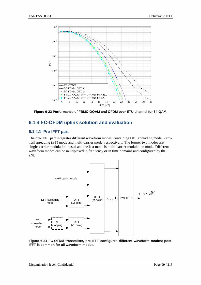
FANTASTIC-5G Deliverable D3.1
Dissemination level: Confidential Page 99 / 213
Figure 6-23 Performance of FBMC-OQAM and OFDM over ETU channel for 64-QAM.
6.1.4 FC-OFDM uplink solution and evaluation
6.1.4.1 Pre-IFFT part
The pre-IFFT part integrates different waveform modes, containing DFT spreading mode, Zero-Tail spreading (ZT) mode and multi-carrier mode, respectively. The former two modes are single-carrier modulation-based and the last mode is multi-carrier modulation mode. Different waveform modes can be multiplexed in frequency or in time domains and configured by the eNB.
IFFT(M-point)
Post-IFFT
DFT(N1-point)
ZPmapping
DFT(N2-point)
ZT spreading
mode
DFT spreading mode
multi-carrier mode
Figure 6-24 FC-OFDM transmitter, pre-IFFT configure s different waveform modes; post-IFFT is common for all waveform modes.

FANTASTIC-5G Deliverable D3.1
Dissemination level: Confidential Page 100 / 213
6.1.4.2 Post-IFFT part
In the post-IFFT process, the conventional usage of CP is avoided. But, a windowing operation is used instead. If we denote as the outputs of the IFFT transform, with (being the IFFT size), the FC-OFDM time domain symbol, , for , is cyclically extended from samples to samples (with being a positive integer) and then a window of length samples is applied, i.e. for , we have
with being the modulo-M operation; being a delay factor (positive integer). An example of
is shown in Figure 6-25, where and can be arbitrarily chosen under the condition of and is the window function, which can be expressed as
The window design is not unique, one example is that and
.
Figure 6-25 Windowing process in post-IFFT part.
The consecutive FC-OFDM symbols are then sequentially arranged in the time domain such that the FC-OFDM symbols are overlapped in time domain with overlapped samples, where (overlapping factor) is a positive integer; but it can also be zero, implying that FC-OFDM symbols are not at all overlapped in time domain. If we want to maintain the same spectral efficiency of the LTE CP-OFDM system (assuming the CP length is ), the relation between , and is
. As an example, when , . If we further increase , then can be also increased, while the same spectral efficiency is still maintained. An optimum value of under a given spectral efficiency is for further study.
6.1.4.3 Performance evaluation
PSD evaluation

FANTASTIC-5G Deliverable D3.1
Dissemination level: Confidential Page 101 / 213
In Figure 6-26, we evaluate the power spectral density of FC-OFDM and compare it with waveforms DFT-s-OFDM. The PSD is evaluated for FC-OFDM with DFT spreading configuration mode. Moreover the impact of non-linearity of PA is also taken into account. The performance shows that FC-OFDM has better OOB leakage and potentially more edge subcarriers can be modulated.
Figure 6-26 PSD evaluation, FC-OFDM with DFT spread ing configuration mode.
Robustness to relaxed time synchronization
Here, we evaluate the capacity of FC-OFDM to tolerant timing (frame) mismatch. Our assumed the test case is the coexistence of hybrid closed-/open-loop synchronization (CLS/OLS). The CLS refers to the case that the uplink transmission is perfect time synchronized with eNB, using LTE-like timing advance (TA) for each user (i.e. 1-to-1 TA). However, the OLS assumes that the TA is not performed for each user, individually; but instead, the same TA value is shared by a group of users, i.e. 1-to-many TA. This synchronization mechanism could be envisioned for MMC service to reduce the downlink signalling overhead thanks to 1-to-many TA. Furthermore, we assume that a dedicated subband is reserved for the OLS-based transmission (denoted as OLS-subband). Moreover, the CLS-subband is assumed to be adjacent to the OSL-subband. Thus, we evaluate the interference level due to the synchronization error within the OLS-subband, i.e. intra-subband interference. In addition, we also evaluate the interference causing from the OLS-subband to the CLS-subband, i.e. inter-subband interference. The results of the intra-subband and inter-subband interference evaluations are given in Figure 6-27 and Figure 6-28. It is shown that the DFT-s-OFDM, due to the usage of CP, is robust to the positive time offset. However, it is difficult in the OLS to keep the time offset to be positive only. FC-OFDM with ZT spreading mode, on the other hand, has more symmetrical robustness against both positive and negative time offset, which is very suitable for OLS-based transmission.
-8 -6 -4 -2 0 2 4 6 8-90
-80
-70
-60
-50
-40
-30
-20
-10
0
10
frequency (MHz)
PS
D (
dB)
DFT-S-OFDM
FC-OFDM no clippingFC-OFDM clip at 6 dB
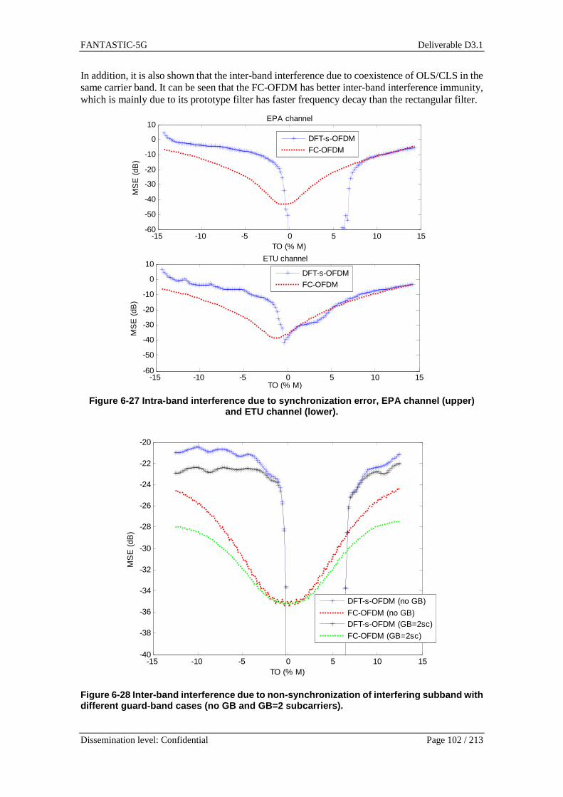
FANTASTIC-5G Deliverable D3.1
Dissemination level: Confidential Page 102 / 213
In addition, it is also shown that the inter-band interference due to coexistence of OLS/CLS in the same carrier band. It can be seen that the FC-OFDM has better inter-band interference immunity, which is mainly due to its prototype filter has faster frequency decay than the rectangular filter.
Figure 6-27 Intra-band interference due to synchron ization error, EPA channel (upper)
and ETU channel (lower).
Figure 6-28 Inter-band interference due to non-sync hronization of interfering subband with different guard-band cases (no GB and GB=2 subcarri ers).
-15 -10 -5 0 5 10 15-60
-50
-40
-30
-20
-10
0
10
TO (% M)
MS
E (
dB)
EPA channel
DFT-s-OFDM
FC-OFDM
-15 -10 -5 0 5 10 15-60
-50
-40
-30
-20
-10
0
10
TO (% M)
MS
E (
dB)
ETU channel
DFT-s-OFDM
FC-OFDM
-15 -10 -5 0 5 10 15-40
-38
-36
-34
-32
-30
-28
-26
-24
-22
-20
TO (% M)
MS
E (
dB)
DFT-s-OFDM (no GB)
FC-OFDM (no GB)DFT-s-OFDM (GB=2sc)
FC-OFDM (GB=2sc)

FANTASTIC-5G Deliverable D3.1
Dissemination level: Confidential Page 103 / 213
PAPR evaluation
The PAPR evaluation is given in Figure 6-29, where FC-OFDM with DFT spreading configuration is used to compare with DFT-s-OFDM. The resulting PAPR of FC-OFDM is slightly higher than DFT-s-OFDM by around 0.2 dB, which is independent of the constellation order. Therefore, the PAPR loss of FC-OFDM, due to the non-rectangular prototype filter, is indeed marginal. For the other configuration modes, i.e. ZT spreading and multi-carrier modes, the PAPR will naturally become higher. For the multi-carrier mode, FC-OFDM has also 0.2 dB higher PAPR than the CP-OFDM. While, for the ZT spreading mode, the PAPR increase depends on the number of zero heads and tails, as well as the allocated number of PRBs.
Figure 6-29 PAPR evaluation.
6.1.5 Pulse-shaped OFDM: concept and performance
6.1.5.1 Motivation and concept
Although OFDM is widely-used in current communication systems, it exhibits certain drawbacks, such as spectral and energy efficiency loss due to the CP usage, the vulnerability to frequency-dispersion, and comparable high out-of-band emission [METIS13-D11, 5GN13-D21, Bel10, EMP15-D15]. To address those challenges OFDM encounters, we discuss new waveform designs aiming at achieving better spectral and energy efficiency, better time-frequency localization, robustness to the timing and frequency dispersion, as well as the flexibility customized to the newly introduced services. Our proposal is pulse-shaped OFDM (P-OFDM) [ZSW+15, ZSG+16, JW07, MSG+07], where subcarrier signals are individually filtered with a uniform filter. On the one hand, the pulse shape design reduces Out of Band (OOB) power leakage; on the other hand, it enables the reduction of ISI and ICI in doubly dispersive channels. Potentially, in order to achieve certain link level
0 1 2 3 4 5 6 7 810
-4
10-3
10-2
10-1
100
γ (in dB)
Pr(
PA
PR
>γ)
FC-OFDM (QPSK)
DFT-S-OFDM (QPSK)FC-OFDM (64QAM)
DFT-S-OFDM (64QAM)
5.5 6 6.5 7
10-3

FANTASTIC-5G Deliverable D3.1
Dissemination level: Confidential Page 104 / 213
performance in time/frequency dispersive channels, P-OFDM requires less overhead than CP-OFDM in terms of guard bands, leading to higher energy efficiency and spectral efficiency. We assume that D[,q is the complex-valued information symbol at the ®th subcarrier and the $th symbol time, where ® = 0,… ,] with ]the number of subcarriers. The baseband transmit signal of P-OFDM is given by [Boe99]
h;¯> = + + D[,q°[,q;¯>,^L_[`a
pbq`Lb
where the transmission function °[,q;¯>is a modulation of a transmit pulse °;¯> that °[,q;¯> =°;¯ − $±>jkA²[³;�LqS> for certain ±, ´ > 0. The symbol period and the subcarrier spacing are denoted by ± and , respectively. At the receiver side, the demodulated symbolDµ[,q is reconstructed by computing the inner product of the received signal E;¯> and ¶[,q;¯> as Dµ[,q = ⟨E, ¶[,q⟩ where ¶[,q;¯> is the TF shifted version of the receive pulse ¶;¯> as ¶[,q;¯> = ¶;¯ −$±>jkA²[³;�LqS>. As seen from the system model, this multicarrier system can be characterized using the quadruple;T, F, g;t>, γ;t>> [SB03, Str98, Boe99, JW07]. Since the design parameters contain not only the symbol period T and subcarrier spacing F, but also pulse shapesg;t>, γ;t>as additional degree of freedoms, this multicarrier system is also termed as P-OFDM. Depending on the detailed pulse design, the pulse shaping module contains several special cases as CP adding/removal, windowing, overlapping and sum. Loosely speaking, P-OFDM transmits complex-valued (e.g., QAM-modulated) OFDM signals, and exploits the pulse shaping as one additional degree of freedom to design the OFDM systems. P-OFDM allows for the overlapped filters in time domain or/and in frequency domain.
Essentially, the P-OFDM signal employs uniform subcarrier level filtering which potentially allows for an efficient implementation. It generalizes several widely used waveforms such as CP-OFDM, ZP-OFDM, windowed OFDM and filtered multi-tone (FMT).
The connections between widely-used CP-OFDM and P-OFDM are as follows: Based on the definition, CP-OFDM is a special case of P-OFDM. Specifically, the transmit pulse g;t>is defined as a rectangular pulse of length T. On the receiver side, removing CP can be interpreted as windowing with a rectangular shaped receive filter γ;t> of lengthT − T½¾. This implies that CP-OFDM design follows the bi-orthogonal principle with different pulse shaping filters employed at the TX and the RX side, i.e. g;t> ≠ γ;t>.The pulses used for CP-OFDM are shown to be the optimal in time-invariant channels with power delay profile (shorter than length of CP TÀÁ) and with infinite target SINR (if SNR mismatching loss is ignored). However, the optimality diminishes if the channel is time variant / frequency dispersive or the length of channel delay is longer than TÀÁ.
It is important to note that windowing OFDM is closely connected to the well-studied topic of pulse shaping theory for OFDM system. The commonly used windowing operation in practice is merely one type of a short non-rectangular pulse shape in OFDM systems.
There is another category of waveforms with sub-band filtering, i.e. filtered OFDM (F-OFDM) [AJM15, ZJC+2015]. F-OFDM builds on an OFDM system where individual sub-bands constituted by the aggregation of M subcarriers is filtered. This allows maintaining full compatibility with the CP-OFDM signals and its frame structure. The choice of the filter in F-OFDM is quite flexible, and it may be chosen with the aim to minimize OOB radiation and in-band distortion. Also, the actual performance of the different filters for F-OFDM highly depends on the considered scenario and the particular filter design. As the filter tails of an F-OFDM symbol overlap with the preceding and succeeding symbols, they will introduce a certain amount of ISI even for frequency flat fading channels; however, this can be kept rather small by a proper choice

FANTASTIC-5G Deliverable D3.1
Dissemination level: Confidential Page 105 / 213
of the filter. The filter design is steered by the well-known trade-off between time and frequency localizations: The shorter the filter time response, the broader the occupied spectrum, yielding higher OOB radiation. With a longer time response of the filter, the OOB leakage can be substantially reduced; however, ISI may become large unless very large guard times are inserted. Hence, the careful design of the filter is important in order to allow for low out of band distortion while limiting in-band distortion owing to filtering and increased ISI. Briefly speaking, sub-band filtering is an efficient way of signal filtering for the purpose to reducing the OOB by system subbands, while keeping the merits of CP-OFDM. However, attention might need to be paid that the lower leakage of OOB power might be constrained by the non-linear effect of RF (e.g., power amplifier) in practice.
The P-OFDM scheme has several favorable properties, such as low receiver complexity, and flexibility to achieve robustness against both time and frequency dispersion. Therefore, we focus on P-OFDM in the following. We evaluate the performance of P-OFDM in several challenging scenarios that will be encountered in 5G.
6.1.5.2 Low complexity implementation
We consider P-OFDM systems with an overlapping factor �, where � is the number of symbols over which the filter spreads. Since P-OFDM signals can be synthesized and analysed by a uniform DFT-based filterbank, its transceiver implementation for arbitrary rational time overlapping factor � can be efficiently realized bya polyphase network (PPN) [VAI90] after the IDFT at the transmitter side, and before the DFT at receiver side. For the short pulse shape where �9 ≈ 1, the PPN structure can be simplified to the ”CP”, ”zero-padding” and ”windowing” operations according to the specific design of °;¯> and ¶;¯>. For a general setting of�, the overall PPN based P-OFDM implementation will only introduce a minor complexity overhead. Taking the whole PHY-layer baseband processing into account, the overhead to modulator and demodulator part due to the usage of PPN is rather minor [BSR+11].
6.1.5.3 Support of flexible spectral usage
To enable flexible spectral usage, low out-of-band power leakage is necessary. To make a fair comparison between P-OFDM and CP-OFDM, we assume both have the same overhead and the overhead is 7% which corresponds to the normal CP overhead in LTE. From its power spectral density (PSD) analysis delineated in Figure 6-30, higher OOB power leakage is observed for OFDM than P-OFDM. One remark is that, in practice, a subband-wise low pass filtering can be adopted to shape and fit in the spectral mask, as long as the shaping does not invoke a huge loss in error vector magnitude (EVM).
Figure 6-30 PSD analysis of P-OFDM.
In the above figure, LTE setting of 15 KHz subcarrier spacing for 20 MHz bandwidth is applied. Assuming the required spectral leakage is -50 dBc/Hz (the linearity of RF unit should be

FANTASTIC-5G Deliverable D3.1
Dissemination level: Confidential Page 106 / 213
considered for meeting the actual spectral mask requirement), the required guard subcarrier numbers (without additional subband filtering) can be summarized in the Table 6-5:
Table 6-5 Guard Subcarrier requirement (Single Side ) and EVM.
For a more aggressive spectrum usage with less guard subcarrier overhead, additional subband-wise filtering (e.g., F-OFDM and UF-OFDM) can also be applied to OFDM-based signal. However, the trade-off between EVM, OOB emission, and particularly the linearity for RF unit (cost and power efficient) at both the BS and the UE sides should be carefully reviewed.
6.1.5.4 Support of asynchronous TA-free transmissio n
In current uplink transmission, due to radio propagation latency, the timing misalignment is present for the uplink signal arrival to the base station, unless a close-loop Timing Advance (TA) adjustment is performed. The scenario is depicted in Figure 6-31.
Figure 6-31 Asynchronous uplink Massive Access with out TA.
Due to different radio propagation delay, the signals from the two UEs are not aligned at the BS, namely, no closed loop timing synchronization is applied. We apply the designed pulse shape with K = 4, TF = 1.07 and evaluate the link performance in such asynchronous transmission scenario. LTE CP-OFDM with normal length CP is adopted as baseline for comparison. Link performance in terms of coded BLER can be found in Figure 6-32. It can be observed that P-OFDM with the designed pulse significantly outperforms CP-OFDM in a loosely synchronized scenario.

FANTASTIC-5G Deliverable D3.1
Dissemination level: Confidential Page 107 / 213
Figure 6-32 BLER performance for asynchronous trans mission (2UEs, 1BS, ETU
channels with uniformly distributed timing offset w ithin [0, 13] ��). 6.1.5.5 Support of high mobility scenarios
High mobility scenario has been recognized as a key component for the next generation radio technology to support a variety of new services, e.g. high speed train (HST) and vehicular to vehicular (V2V), as shown in Figure 6-33. For both cases, we apply the designed pulse shape with � = 4, ±´ = 1.25. For the high speed train scenario, LTE defined CP-OFDM is taken as baseline. Figure 6-34 depicts the BLER performance for P-OFDM and OFDM, while solid lines show the performance with ideal channel state information and dash lines indicate the performance with LS-based channel estimation. As clearly shown, P-OFDM outperforms OFDM due to the robustness to the time and frequency distortions caused by high mobility.
Figure 6-33 High Mobility scenario for HST/V2V.
For V2V scenario, based on the channel statistics found in the literature [MMK11, AI07, BS05], a subcarrier spacing of 60 kHz is chosen in order to cover extremely high velocity scenario with guaranteed link performance. BLER performance is shown in Figure 6-35. P-OFDM system shows better robustness against channel time and frequency dispersion.
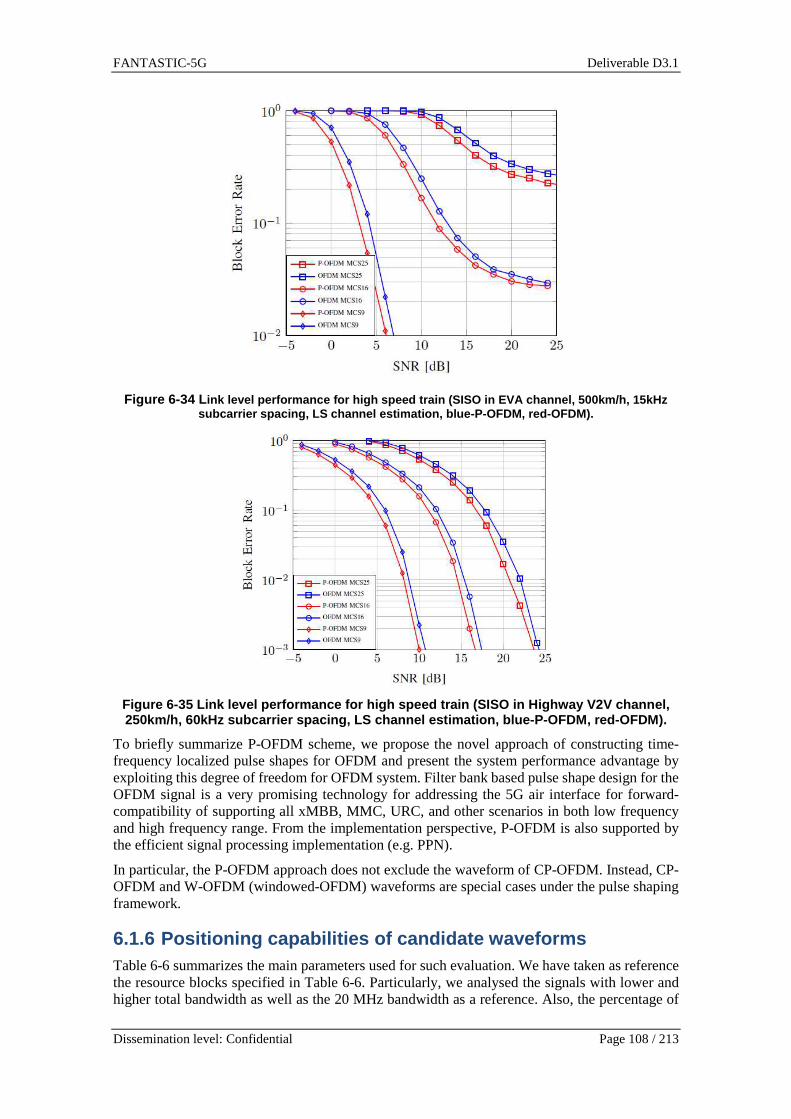
FANTASTIC-5G Deliverable D3.1
Dissemination level: Confidential Page 108 / 213
Figure 6-34 L ink level performance for high speed train (SISO in EVA channel, 500km/h, 15kHz
subcarrier spacing, LS channel estimation, blue-P-OFD M, red-OFDM).
Figure 6-35 Link level performance for high speed t rain (SISO in Highway V2V channel, 250km/h, 60kHz subcarrier spacing, LS channel estim ation, blue-P-OFDM, red-OFDM).
To briefly summarize P-OFDM scheme, we propose the novel approach of constructing time-frequency localized pulse shapes for OFDM and present the system performance advantage by exploiting this degree of freedom for OFDM system. Filter bank based pulse shape design for the OFDM signal is a very promising technology for addressing the 5G air interface for forward-compatibility of supporting all xMBB, MMC, URC, and other scenarios in both low frequency and high frequency range. From the implementation perspective, P-OFDM is also supported by the efficient signal processing implementation (e.g. PPN).
In particular, the P-OFDM approach does not exclude the waveform of CP-OFDM. Instead, CP-OFDM and W-OFDM (windowed-OFDM) waveforms are special cases under the pulse shaping framework.
6.1.6 Positioning capabilities of candidate wavefor ms Table 6-6 summarizes the main parameters used for such evaluation. We have taken as reference the resource blocks specified in Table 6-6. Particularly, we analysed the signals with lower and higher total bandwidth as well as the 20 MHz bandwidth as a reference. Also, the percentage of

FANTASTIC-5G Deliverable D3.1
Dissemination level: Confidential Page 109 / 213
pilots devoted for ranging purposes is trade-off, jointly with their allocation (random and place at the outer sides of the band). The Resource Block Types in the table correspond to the following services: 1) legacy MBB; 3) MBB/MCC/V2X, low latency, low-mid frequency band; 4) MBB, low latency, high frequency band; 5) MBB, low latency, high frequency band; and 7) MCC, low cost.
Table 6-6 Parameter sets for CRB evaluation for the selected RB types.
Resource Block Type 1
Subcarrier spacing 15 kHz
Total System Bandwidth, BW [MHz] 5 20 320
Number of subcarriers, Nsc = Fs/∆f 512 2048 32769
Subcarriers for ranging (5%) 26 102 1638
Subcarriers for ranging (20%) 102 410 6554
Resource Block Type 3
Subcarrier spacing 75 kHz
Total System Bandwidth, BW [MHz] 5 20 320
Number of subcarriers, Nsc = Fs/∆f 102 410 6554
Subcarriers for ranging (5%) 5 20 328
Subcarriers for ranging (20%) 20 82 1311
Resource Block Type 4
Subcarrier spacing 750 kHz
Total System Bandwidth, BW [MHz] 5 20 320
Number of subcarriers, Nsc = Fs/∆f 10 41 655
Subcarriers for ranging (5%) 1 2 33
Subcarriers for ranging (20%) 2 8 131
Resource Block Type 5
Subcarrier spacing 1,50 MHz
Total System Bandwidth, BW [MHz] 5 20 320
Number of subcarriers, Nsc = Fs/∆f 5 20 328
Subcarriers for ranging (5%) 0 1 16
Subcarriers for ranging (20%) 1 4 66
Resource Block Type 7

FANTASTIC-5G Deliverable D3.1
Dissemination level: Confidential Page 110 / 213
Subcarrier spacing 3,75 kHz
Total System Bandwidth, BW [MHz] 5 20 320
Number of subcarriers, Nsc = Fs/∆f 2048 8192 131075
Subcarriers for ranging (5%) 102 410 6554
Subcarriers for ranging (20%) 410 1638 26215
The results for these test cases are shown in the Figure 6-36 - Figure 6-40. Results confirm some intuitions that are worth highlighting in view of signal design accounting for ranging capabilities. First, increasing the total bandwidth improves the overall ranging capabilities as the number of effective subcarriers increase as well. Secondly, since subcarrier spacing has an impact on symbol period, higher subcarrier spacing benefit time-delay estimation. Another important remark is related to the allocation of those subcarriers aimed for ranging. As shown in [Zan08], and commented here earlier, it is desirable to have these subcarriers allocated at the outer sides of the frequency band. To evaluate the differences in placing them there or, alternatively, randomly within the set of possible subcarriers, the figures include a comparison of that curves as well. It is clear that uniform random placement is detrimental compared to outer band allocation, in most of the cases implying losses of several dB. Finally, there are some configurations where the number of available subcarriers is very low (e.g. RB#4 at 5MHz). Additionally, it is worth mentioning that to satisfy the constraint that ∑ ,-A = )*-∈012 , a uniform power allocation such that ,- =«)*/)?* was considered. This implies a trade-off between the percentage of active subcarriers and the allocated power. If the same power is used for all cases (i.e. 5% and 20%) then the results are better when considering the largest number of subcarriers, however, care should be taken when there is a budget on the total power since increasing the percentage of useful subcarriers does not impact strongly (at least going from 5% to 20%).

FANTASTIC-5G Deliverable D3.1
Dissemination level: Confidential Page 111 / 213
Figure 6-36 Estimation accuracy bounds for differen t setups on the Resource Block Type 1.

FANTASTIC-5G Deliverable D3.1
Dissemination level: Confidential Page 112 / 213
Figure 6-37 Estimation accuracy bounds for differen t setups on the Resource Block Type 3.

FANTASTIC-5G Deliverable D3.1
Dissemination level: Confidential Page 113 / 213
Figure 6-38 Estimation accuracy bounds for differen t setups on the Resource Block Type 4.

FANTASTIC-5G Deliverable D3.1
Dissemination level: Confidential Page 114 / 213
Figure 6-39 Estimation accuracy bounds for differen t setups on the Resource Block Type 5.
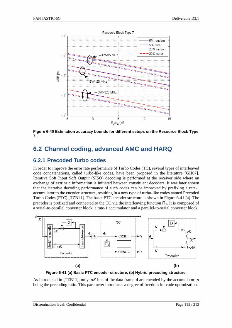
FANTASTIC-5G Deliverable D3.1
Dissemination level: Confidential Page 115 / 213
Figure 6-40 Estimation accuracy bounds for differen t setups on the Resource Block Type 7.
6.2 Channel coding, advanced AMC and HARQ
6.2.1 Precoded Turbo codes In order to improve the error rate performance of Turbo Codes (TC), several types of interleaved code concatenations, called turbo-like codes, have been proposed in the literature [GH07]. Iterative Soft Input Soft Output (SISO) decoding is performed at the receiver side where an exchange of extrinsic information is initiated between constituent decoders. It was later shown that the iterative decoding performance of such codes can be improved by prefixing a rate-1 accumulator to the encoder structure, resulting in a new type of turbo-like codes named Precoded Turbo Codes (PTC) [TZB11]. The basic PTC encoder structure is shown in Figure 6-41 (a). The precoder is prefixed and connected to the TC via the interleaving function Π1. It is composed of a serial-to-parallel converter block, a rate-1 accumulator and a parallel-to-serial converter block.
(a) (b)
Figure 6-41 (a) Basic PTC encoder structure, (b) Hy brid precoding structure.
As introduced in [TZB11], only Ä� bits of the data frame d are encoded by the accumulator, Ä being the precoding ratio. This parameter introduces a degree of freedom for code optimization.

FANTASTIC-5G Deliverable D3.1
Dissemination level: Confidential Page 116 / 213
As an alternative to this PTC scheme, we propose a hybrid precoding structure [GAD15], which precodes the whole data sequence and introduces a new parameter Å, 0 ≤ Å ≤ 1, to define the serial-to-parallel precoding ratio (see Figure 6-41 (b)). Thus, Å� parities and ;1 − Å>� data symbols of the accumulator are encoded by the TC. The advantage of this precoding structure over the previous one is that it allows the SISO decoder of the accumulator to exchange extrinsic information on the whole turbo encoded sequence for all values of Å. Note that for Å = 0, the coding structure corresponds to the classic TC, since all the parities of the accumulator are punctured. By increasing the value of Å, the serial concatenation between the accumulator and the TC concerns a higher number of data bits. Therefore, asymptotic performance improvements are expected at the expense of a loss in convergence performance compared to the one of the classic TC. The tradeoff between convergence and asymptotic performance of the hybrid PTC is then controlled by the serial-to-parallel precoding ratio Å.
The hybrid PTC can be seen as a three-dimensional TC, in which the first dimension corresponds to the precoder and the other two dimensions correspond to the constituent codes of the TC. Therefore, the precoder and TC interleavers, Π1 and Π2 have to be designed considering the three-dimensional nature of the hybrid PTC. Thus, interleaver design criteria, such as span [BSD+04] and correlation girth [Sao10], proposed for a classic TC have to be revisited for the three-dimensional case. We have designed interleavers for the hybrid PTC scheme based on the Almost Regular Permutation (ARP) model [BSD+04].
Since the design of an efficient couple of interleavers Π1 and Π2 is more complex than the search for a single interleaver in the case of a conventional TC, the selection process of Π1 and Π2 was carried out through the following steps.
1) Generate ARP candidates for Π2: A group of ARP interleaver candidates for Π2 is generated. The values of the minimum span N[ÇqA and correlation girth °A are maximized by construction due to the ease of including these criteria in the ARP model.
2) Select Π2 in terms of the TC .[Çq: The best candidate for Π2 is identified as the one conferring the larger minimum Hamming distance .[Çq value to the TC.
3) Identify the best ARP candidates for Π1: A group of interleaver candidates for Π1 is generated as in step 1). Then, a restricted group of candidates for Π1 is composed of the candidates allowing the larger values of N[Çq_,Aand °_,A.
4) Select Π1in terms of the hybrid PTC .[Çq: Finally, the best candidate for Π1 is determined as the one generating the larger .[Çq value in the hybrid PTC.
These guidelines were applied to design interleavers for the hybrid PTC with coding rate I =4/5 and data sequence size � = 1504. Error rate performance was simulated over the AWGN channel with a BPSK modulation and a maximum of sixteen decoding iterations, using the Maximum A Posteriori (MAP) algorithm [BCJ+74].

FANTASTIC-5G Deliverable D3.1
Dissemination level: Confidential Page 117 / 213
Figure 6-42 Frame error rate performance comparison among the hybrid PTC for φ =
0.04, a conventional tail-biting TC, and the LTE co de over the AWGN channel for R = 4/5, K = 1504, and CRSC constituent codes with generator polynomials (13, 15) 8.
Figure 6-42 shows the Frame Error Rate (FER) performance of the hybrid PTC using the selected couple of interleavers for Π1 and Π2, whose minimum Hamming distance .[Çq is equal to 11. We observe that the error floor performance of a classic TC, using tail-biting termination and an ARP interleaver with .[Çq of 9, is improved by almost two decades with the proposed hybrid PTC. In addition, the proposed hybrid PTC achieves a gain of about 0.38 dB in convergence and almost 4 decades in error floor, compared to the puncturing pattern and the interleaver adopted in LTE.
6.2.2 Frequency Quadrature Amplitude Modulation In this section, we present performance evaluation results for FQAM technique. We consider a system consists of three cells, where the users’ desired signal in a cell is corrupted by interference from the other two cells. It is assumed that each interfering signal is 3 dB lower than the desired signal, which represent cell-edge users scenario. We implement turbo code of coding rate 1/3, QPSK modulation and MF = 4 for FQAM.
Figure 6-43 and Figure 6-44 show the BLER and throughput, respectively, for FQAM comparing to QAM modulation for cell-edge users. The SNR represents the ratio between the base-station total power and the noise power. As the figure shows, FQAM significantly outperforms the performance of QAM modulation in terms of BLER. This is clearly reflected on the achieved throughput as shown in the results. It is clear from the results that QAM modulation is not suitable for heavy interference environment. On the other hand, FQAM performs very well in such scenarios, making it much more suitable technique for 5G systems. The statistics of the interference in given in [FAN-D41].
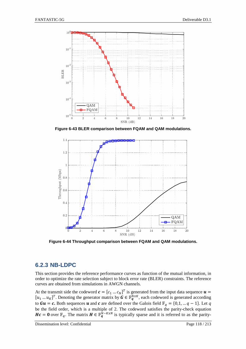
FANTASTIC-5G Deliverable D3.1
Dissemination level: Confidential Page 118 / 213
Figure 6-43 BLER comparison between FQAM and QAM mo dulations.
Figure 6-44 Throughput comparison between FQAM and QAM modulations.
6.2.3 NB-LDPC This section provides the reference performance curves as function of the mutual information, in order to optimize the rate selection subject to block error rate (BLER) constraints. The reference curves are obtained from simulations in AWGN channels.
At the transmit side the codeword È = #É_…Éz%S is generated from the input data sequence Ê =#Ë_…ËP%S. Denoting the generator matrix byÌ ∈ ÍÎzÏP, each codeword is generated according to ÌÊ = È. Both sequences Êand È are defined over the Galois field ÍÐ = Ñ0,1, …c − 1Ò. Let q be the field order, which is a multiple of 2. The codeword satisfies the parity-check equation �È = �over ÍÐ. The matrix � ∈ ÍÎzLPÏz is typically sparse and it is referred to as the parity-

FANTASTIC-5G Deliverable D3.1
Dissemination level: Confidential Page 119 / 213
check matrix. Next, each element of the coded sequence is mapped into several symbols. In other words, the code symbol ÉÓ is mapped into a T complex dimensional vector from the set Ô =ÕÖa⋯ÖÐL_Ø, where ÖÇ ∈ ℂSÏ_ . The multidimensional constellation Ô can be built from the Cartesian product of the standard ]?-QAM constellations with c = ;]?>S. In general, they will depend on the mapping to the number of transmit antennas and channel uses. That is, the symbols can be mapped into ± antennas or transmitted into ± consecutive time slots. In the rest of the section, we stick to the SISO configuration unless otherwise stated. The reason stems from the fact that the analysis is more complicated when the coded symbol are mapped into the transmit antennas than into consecutive time slots. The peculiarities that stand out in MIMO systems are discussed in Section 6.2.4. For the ease of exposition, the labelling is compactly expressed as Ú;ÉÓ> = ÛÓ = Ü"Ó,_…"Ó,SÝS , for 1≤ Þ ≤ ) , where ÉÓ ∈ ÍÐ and ÛÓ ∈ Ô . It is assumed that ß àá"Ó,ÇáAâ = ã�, for 1≤ ä ≤ ±. The transmit processing is illustrated in Figure 6-45.
EncoderSymbol mapping "Þ ,1…"Þ ,±
Ë9 ÉÞ
Figure 6-45 Block diagram of the transmitter.
At the other end of the link, the received vector is given by åÓ = ÛÓ +æÓ, with æÓ being complex Gaussian noise with æÓ~è0;0, Na�S>. Let �S be the T-dimensional identity matrix. To recover the information delivered by the transmitter, the received samples are jointly demapped into the
L-vector êÓ = ÜUÓ,aUÓ,_…UÓ,ÐL_ÝS, which is expressed as
UÓ,Ç = − 1)a;|åÓ − ìÇ|A − |åÓ − ìa|A> ,9 = 0,1,… , c − 1. Finally, as Figure 6-46highlights, the L-vector is fed into the NB-LDPC decoder. Several works have demonstrated that NB-LDPC codes can be decoded with a reasonable complexity by resorting to sum-product, min-sum or min-max algorithms [BD03, DF07, Sav08, BC10, LDG13]. To get the reference curves, we consider the implementation in [BD03] for the NB-LDPC decoder.
Symbol demapper
DecoderåÞ êÞ Ëí9
Figure 6-46 Block diagram of the receiver.
For the design of ACM, it is proposed to leverage on ultra-sparse NB-LPDC codes [PFD98]. Concerning the parameters of the code, the field order has been set to c = 256 and the message length is � = 90. Building upon a mother code of rate 1/2, different rates can be obtained by puncturing and non-binary repetition. The values that are evaluated are gathered in Table 6-7 and Table 6-8.
Table 6-7 Rates obtained with puncturing.
N K
100 108 120 135 150 180
90 910 56
34 23
35 ��
Table 6-8 Rates obtained with non-binary multiplica tive repetition.
N K
180 220 270 360 450 540 630 720 810 900 990 1080 1170 1260
90 �� 922
13 14
15 16
17 18
19 110
111 112
113 114

FANTASTIC-5G Deliverable D3.1
Dissemination level: Confidential Page 120 / 213
Due to the fact that the operations are performed over the Galois field ÍAîï, the code symbols can be straightforwardly mapped into 256-QAM and 16-QAM constellations. Hence, we shall set T=1 and T=2 when 256-QAM and 16-QAM symbols are respectively employed. With symbols drawn from the 2[ -QAM alphabet Ô[ = Ñh_⋯hAðÒ , the mutual information per code symbol is defined with this closed-form expression [PD10]:
ñ 6ã�)a: = Þò°A(256)® rós®− 12[+ßAð
k`_ ôÞò°Aõ+j",õ−&ã�)a �hk − hÇ +��+|�|AöAðÇ`_ ö÷
vøw.
The variable � accounts for the noise samples, which are circularly symmetric and Gaussian distributed with zero mean and variance 1. It has been assumed that symbols hk, hÇ have an average energy symbol equal to 1. The performance of the code is shown in Figure 6-47, which represents the BLER against the mutual information per code symbol.
a) b)
Figure 6-47 BLER vs mutual information in AWGN for a) 256-QAM b) 16-QAM.
Notice that the curve in blue corresponds to the mother code. The ones in red and green delimit the threshold to achieve a BLER equal to 10Lª and 10-2, respectively. The rest of the curves can be readily identified from Table 6-7 and Table 6-8. For selecting the modulation and coding scheme, it is useful to represent the (throughput, ã�/)a ) pairs as in Figure 6-48. The ã�/)athreshold is obtained by inverting the mutual information threshold at the target BLER (e.g. BLER=10−2) from Figure 6-47. The modulation and the code rate are mapped to the throughput
value as follows:ù = Þò°A(256) PSz (1 − JUãI).
Figure 6-48 Throughput against ��/��over an AWGN channel when BLER=10 −2.

FANTASTIC-5G Deliverable D3.1
Dissemination level: Confidential Page 121 / 213
Note that the throughput curves of 256-QAM and 16-QAM overlap for −1.7 dB≤ ã�/)a≤ 15 dB. In this range, we propose to favour 256-QAM to the detriment of 16-QAM. The reason lies in the fact that the mapping scheme is simplified when 256-QAM is employed, because one code symbol is transmitted in one channel access. With 16-QAM two accesses are required. This choice will have an impact on the link adaptation algorithm as detailed in Section 6.2.5.
6.2.4 Mapping schemes for SISO and MIMO communicati on systems
This section addresses the practical implementation aspects that arise when the code symbols generated by the NB-LDPC encoder have to be mapped into single- or multi-antenna systems.
6.2.4.1 SISO
From Section 6.2.3, it can be inferred that in SISO communication systems the code symbols can be transmitted in T consecutive time slots. When the bandwidth is partitioned into narrowband subchannels, the simplest mapping scheme consists in keeping fixed either the subcarrier or the time index. Considering the FBMC/OQAM modulation scheme, which represents one of the most challenging air interfaces, the best option to map the coded symbols is to keep unchanged the subcarrier index [CNM+16]. After performing the equalization and the OQAM post-processing, the input-output relation on the qth subcarrier becomes úÐ#9% = "Ð#9% + äÐ#9% + $Ð#9%. Let "Ð#9% be the symbol transmitted on the frequency-time position ;c, 9>. It is important to recall the "Ð#9% may be drawn from the 256-QAM or the 16-QAM constellation diagrams. The term $Ð#9% accounts for the equalized noise on the qth subcarrier, which is distributed as follows: $Ð#9%~è0 û0, Na/áü��Ð�áAý. Letü��Ð� denote the channel frequency response evaluated at
the radial frequency �Ð. The term äÐ#9% is the residual interference that may appear when the channel is not properly compensated with single-tap equalizers. The power of äÐ#9% has been formulated in [MMP13] with this closed-form expression
ã àáäÐ#9%áAâ = �ÐA = É ã�4;]/2)ª áü′��Ð�áAáü��Ð�áA , where ] is the number of subcarriers, É is a constant that depends on the prototype pulse and ü′��Ð� corresponds to the derivative of the channel frequency response at �Ð . The channel quality metric is given by
¶Ð = ã�z�á{����ál + �ÐA. Imagine that Õ"Ð#9%⋯"Ð#9 + ± − 1%Ø convey information of the code symbol ÉÓ, then it follows that the demapper can compute the 256 symbol-levels as follows:
UÓ,Ç = + áúÐ#9 + 7% − ha,káAz�á{����ál + �ÐASL_k`a −áúÐ#9 + 7% − hÇ,káAz�á{����ál + �ÐA ,ä = 0,1,… ,255.
For ± = 1, hÇ,a ∈256-QAM, while for ± = 2, hÇ,a, hÇ,_ ∈16-QAM. Note that the same expressions can be used with other modulation formats, as long as the variance of the filtered noise and the intrinsic interference are properly modelled. Ifthe modulation is orthogonal, like OFDM, then �ÐA = 0.

FANTASTIC-5G Deliverable D3.1
Dissemination level: Confidential Page 122 / 213
6.2.4.2 MIMO
Let us consider the plain spatial multiplexing scheme, where no precoding is applied. This means that the number of streams that are simultaneously transmitted is equal to the number of transmit antennas, i.e. )S .When the spatial diversity comes into play, the demodulated signal after equalizing the channel on the qth subcarrier is given by åÐ#9% = ÜúÐ_#9%⋯úÐz�#9%ÝS = ÛÐ#9% + �Ð#9% + �Ð#9%. Analogously to the SISO case, ÛÐ#9% = Ü"Ð_#9%⋯"Ðz�#9%ÝS is the vector of symbols, �Ð#9% =ÜäÐ_#9%⋯ äÐz�#9%ÝS is the residual interference and �Ð#9% = Ü$Ð_#9%⋯$Ðz�#9%ÝS is the noise at the output of the equalizer. When the ZF equalizer is applied in the FBMC/OQAM context, the noise covariance matrices and the interference covariance matrix are formulated as:
ãÕ�Ð#9%�Ð�#9%Ø = �Ç� = É ã�4;]/2)ª���Ð�L_�′��Ð��′��Ð�{���Ð�L{
ãÕ�Ð#9%�Ð�#9%Ø = �q� = )a���Ð�L_���Ð�L{ . Let ���Ð�¬ℂz�Ï_ denote the channel matrix evaluated at the radial frequency�Ð and �′��Ð� corresponds to its derivate. The constant É depends on the prototype filter. The general expression for �Ç� and �q�, which is valid for any MIMO decoding matrix, can be found in [MG16]. If the
orthogonality is preserved, like in OFDM, then �� = �.It is worth highlighting that the )S
spatial layers can be used to transmit )S different codewords, each one fed into a different antenna port. In this case, the channel quality metric associated to the sth codeword and the qth subcarrier is
¶?,Ð = ã���Ç��?? + ��q��?? ,1 ≤ h ≤ )S . In notation terms, ��Ç��?? and ��q��?? account for the (s,s)th element of matrix �Ç� and �q� ,
respectively. Relying on ¶?,Ð, soft demapping and link adaptation can be independently performed on each spatial layer in a straightforward manner. In this case, it is possible to draw an analogy between each layer and a SISO communication system.
Alternatively, the transmit vector ÛÐ#9% can be generated from code symbols of the same codeword. This means that instead of simultaneously transmitting )S codewords, a single codeword is mapped into the )S transmit antennas. The strategy is depicted in Figure 6-49.
EncoderSymbol mapping
1Multicarrier modulation
NTMulticarrier modulation
⋮
Figure 6-49 Modulation and mapping procedures with � transmit antennas.
For the ease of exposition, in the rest of the section we focus on )S = 2.When the symbols are 256-QAM modulated, the L-vector associated to frequency-time position (q,k) can be easily computed as
UÓ,Ç? = áúÐ?#9% − haáA��Ç��?? + ��q��?? −áúÐ?#9% − hÇáA��Ç��?? + ��q��?? ,ä = 0,1,… ,255, h = 1,2,

FANTASTIC-5G Deliverable D3.1
Dissemination level: Confidential Page 123 / 213
under the assumption that hǬ256-QAM and that "Ð?#9% is related the code symbol ÉÓ. To facilitate the link adaptation and the soft demapping when "Ð_#9%, "ÐA#9%¬16-QAM, it would be desirable that the sources of distortion of those samples to are jointly processed, i.e. ÕúÐ_#9%, úÐA#9%Ø, were uncorrelated. Unfortunately this is not the case. To overcome this issue, the two 16-QAM symbols that compose a given coded symbol have to be transmitted in different time-frequency elements. By introducing sufficiently large time and frequency offsets, the L-vector can be obtained as
UÓ,Ç = áúÐ_#9% − ha,_áA − áúÐ_#9% − hÇ,_áA��Ç��__ + ��q��__ + úÐp∆A #9+∆�% − ha,A
A − áúÐA#9+∆�% − hÇ,AáA��Ç��∆�AA + ��q��∆
�AA , for ä = 0,1, … ,255 and hÇ,_, hÇ,A¬16-QAM. If the pulses are frequency-localized, the cross-correlation is approximately 0 by setting ∆}= 2 and ∆�= 0. It has been considered that the code symbol ÉÓ is mapped into the symbols "Ð_#9% and "Ðp∆
A #9+∆�%. It is relevant to stress that the
mutual information related to symbols that convey information of ÉÓ can be computed as follows: 0.5 6ñ�¶_,Ð� + ñ û¶A,Ðp∆ý:. If the cross-correlation is not zero, it is not be possible to exploit the
formulas obtained in SISO AWGN channels, making the design of link adaptation algorithms more complex. If the number of antennas is a multiple of 2, the proposed approach could be easily extended by grouping the antennas in pairs.
6.2.5 Link adaptation with adaptive code and modula tion This section tackles the link adaptation problem in frequency selective scenarios. Due to its excellent trade-off between complexity and performance, the modulation and coding schemes will be selected according to the algorithm presented in [SBC07]. Suppose that the scheduler assigns L RBs to a given user, which may not be contiguous. The triplet (®(Þ), ,Ó , ¶Ó) denotes the number of bits per symbol, the transmit power and the channel quality metric associated to the lth RB. Without loss of generality it is assumed that the RB is formed by $} subcarriers and $�time slots. In this case, the SINR measured in all the frequency-time units can be mapped into one metric by performing the average proposed in [SBC07], i.e.,
�Ó = KL_õ 1$�$}++K�¶ÇkÓ �q
k`_q�
Ç`_ ö + (1 − )®ä$Ç,k�¶ÇkÓ �. Let ¶ÇkÓ be the SINR measured in the (ä, 7) th position of the lth RB. The function used for averaging is given by K(") = Þò°A(1 + "). If the SINR variance within RBs is significant, the parameter should be set to 0.85.
The ACM that is proposed relies on the mutual information and is based on averaging the code rates of each RB. The modulation and coding schemes that are selected to evaluate the algorithm are gathered in Table 6-9. Note that 16-QAM can only be used with a reduced number of code rates. As Figure 6-48 suggests, the SNR range of interest can be covered with 27 combinations.
Table 6-9 Modulation and coding schemes.
Index Modulation Rate ñ û��z�ýthreshold
for BLER=10-2
Index Modulation Rate ñ û��z�ýthreshold
for BLER=10-2
0 16-QAM 1/14 0.76 14 256-QAM 1/8 1.23
1 16-QAM 1/13 0.83 15 256-QAM 1/7 1.41
2 16-QAM 1/12 0.88 16 256-QAM 1/6 1.61
3 16-QAM 1/11 0.97 17 256-QAM 1/5 1.95

FANTASTIC-5G Deliverable D3.1
Dissemination level: Confidential Page 124 / 213
Under the assumption that �_ ≤ ⋯ ≤ �X and that the transmit energy per multicarrier symbol is ãS = $}ã�U, the algorithm can be summarized with the following steps when the target BLER is 10-2.
1) Distribute the power uniformly, i.e. ,Ó = 1∀Þ. 2) Select the modulation and the coding scheme from Table 6-9for each RB ;1 ≤ Þ ≤ U>
a. Select the modulation i. If −1.7 ≤ ;,Ó�Ó>�o, 256-QAM is selected and thus ®;Þ> = 8
ii. If −5.2 ≤ (,Ó�Ó)�o < −1.7, 16-QAM is selected and thus ®(Þ) = 4 iii. If (,Ó�Ó)�o < −5.2, the RB is discarded, because the constraint JUãI ≤10LA is violated. Consequently, the energy assigned to the lth RB per
time slot, i.e. $}ã�,Ó, is uniformly redistributed among the rest of RBs. b. Calculate the code rate IÓ = �/)Ófrom the BLER performance curves (Figure
6-47) and the evaluation of ñ(,Ó�Ó). We shall remark that the on-line computation of the mutual information is not affordable. However, the mutual information can be efficiently computed by linear interpolation, provided that some values are computed beforehand.
3) Denoting by )Ó the codeword length assigned to the lth RB and by �� the set of the active resource blocks, the code rate that is applied to all RBs and the number of coded symbols are computed as
a. Calculate the code rate I as the weighted average of IÓ, i.e. I = ∑ [(Ó)P/z�����∑ [(Ó)����.
b. Calculate the number of code symbols as )�� = $�$} ∑ [(Ó)Ó��l(Aîï)Ó��� . 4) Determine the number of codewords as )*� = �z���P � 5) Calculate the length of the codeword as ) = �z��z���. Notice that �/)may not coincide
with the exact rate values in Table 6-7 and Table 6-8. If so, the codeword length selection is based on the average mutual information. More specifically, compute first the average mutual information per coded symbol as ñ = ∑ ®(Þ)ñ(,Ó�Ó)Ó���∑ ®(Þ)Ó���
Then, select the closest rate that fulfils the requirement. To this end we shall find the two contiguous codeword lengths ()Ód , )�d) that satisfy )Ód ≤ ) ≤ )�d . If the mutual information threshold ñÓd associated to code rate �/)Ód (obtained from performance curves inFigure 6-47) is above the average mutual information, i.e. ñÓd>ñ, then )Ód = ). Otherwise, the codeword length is set to )�d = ), which results in a more conservative
4 16-QAM 1/10 1.04 18 256-QAM 1/4 2.38
5 16-QAM 1/9 1.16 19 256-QAM 1/3 3.21
6 16-QAM 1/8 1.28 20 256-QAM 9/22 3.94
7 16-QAM 1/7 1.48 21 256-QAM 1/2 4.73
8 256-QAM 1/14 0.74 22 256-QAM 3/5 5.43
9 256-QAM 1/13 0.78 23 256-QAM 2/3 6.01
10 256-QAM 1/12 0.86 24 256-QAM 3/4 6.63
11 256-QAM 1/11 0.93 25 256-QAM 5/6 7.35
12 256-QAM 1/10 1.01 26 256-QAM 9/10 7.74
13 256-QAM 1/9 1.11

FANTASTIC-5G Deliverable D3.1
Dissemination level: Confidential Page 125 / 213
choice than the exact value computed by the algorithm. Finally, the number of codewords
has to be updated as )*� = �z��z �. 6) The )� codewords are jointly interleaved and loaded onto the RBs. The idea is
illustrated in Figure 6-50.
Figure 6-50 Block diagram of a transmitter that emp loys ACM.
6.2.5.1 Numerical results
This section provides some numerical results to assess the combination of NB-LDPC with ACM. Asapplied waveform, the FBMC/OQAM scheme has been considered in single- and multi-antenna architectures. Concerning the mapping in the MIMO configuration, it has been considered that a single codeword is mapped into the transmit antennas, instead of simultaneously transmitting several codewords. The details of this approach are provided in Section 6.2.4. The prototype pulse is designed according to the frequency sampling approach proposed in [Bel01] with an overlapping factor equal to 4. The system parameters are detailed in Table 6-10.
Table 6-10 System parameters.
Bandwidth ;J> 10 MHz Subcarriers ;]> 1024
Active subcarriers ;]�> 600 Subcarrier spacing 15 KHz $} 12 $� 14
Channel model EPA and EVA [36.803] Sampling frequency ;K?> 15.36 MHz
Target BLER 10-2
In Figure 6-51, the curves are represented over the signal to noise ratio (SNR), namely
N)I = I�ãS)aJ , where the symbol rate is I� = K?/], ãS accounts for the transmit energy per multicarrier symbol and )a is the noise spectral density. The average throughput for a given channel realization is given by
ù�! = Þò°A;256))S± I(1 − JUãI). The )S accounts for the number of streams that are simultaneously transmitted, which coincides with the number of transmit antennas in spatial multiplexing schemes. The throughput reveals that in MIMO configurations, it is possible to transmit )S ()S/±) coded symbols in each time-frequency resource element when the modulation of choice is 256-QAM (16-QAM).

FANTASTIC-5G Deliverable D3.1
Dissemination level: Confidential Page 126 / 213
The results of Figure 6-51 corroborate that the target BLER is guaranteed in SISO and MIMO configurations. As it is expected, the higher theN)I, the higher the average throughput. In Figure 6-51, ACM is compared to an algorithm that fixes the modulation across RBs. For a fair comparison, the benchmark can only select the modulation and coding schemes gathered in Table 6-9. Figure 6-51 confirms that significant throughput gains are observed at low SNR when ACM is implemented. Therefore, it is possible to cover the SNR of interest, by using a single modulation. It is important to remark that this conclusion cannot be generalized and may not hold true for other modulation and coding schemes than those gathered in Table 6-9.
a) b)
Figure 6-51 Throughput vs. SNR and BLER vs. SNR a) SISO in EPA channels b) 2x2 MIMO in EVA channels.
6.3 Low PAPR design
6.3.1 PAPR Reduction for FBMC In the main body of this document the two schemes for PAPR reduction are introduced. Here, more details are presented. The first is a general scheme that is applicable to any multicarrier modulation technique. The second is a modification of one of the schemes that were proposed for OFDM to benefit from the special structure of the FBMC/OQAM time signal as depicted in Figure 6-52and hence have additional gains in PAPR reduction.
Figure 6-52 FBMC/OQAM vs. CP-OFDM signal structure.
Two-stage PAPR Reduction

FANTASTIC-5G Deliverable D3.1
Dissemination level: Confidential Page 127 / 213
This is a newly proposed set of PAPR reduction schemes, whereas evident from the naming the reduction is done on two separate stages. The first stage is one of the iterative clipping based schemes (i.e., TR, ACE, TRACE) and then clipping is the second and final stage. This means that it is only a variant of the iterative schemes, where after the predefined maximum number of iterations is reached a further clipping is applied giving the final output. Figure 6-53 is a simplified block diagram for the “two-stage PAPR reduction”.
Figure 6-53 Two-stage PAPR reduction scheme block d iagram.
These schemes achieve the PAPR reduction performance of clipping, while at the same time achieving a better symbol error rate (SER) performance [ED16]. The attractive aspect of this set of schemes would be its potential in finding a compromise between SER performance degradation and the invested computational complexity, while achieving the desired PAPR reduction performance.
Modified Selected Mapping
It is quite appealing to take the overlapping of the FBMC/OQAM time symbols, Figure 4, into consideration for PAPR reduction and thus have an additional gain. Thus, we have devised a new scheme that we called “modified SLM (mSLM)” similar to the scheme proposed in [HH11] for wavelet OFDM. This scheme considers OP hypotheses instead of justOas for the regular SLM, and hence a great increase in computational complexity is expected, as well as an increase in PAPR reduction gain [ED16].
Results
A reduction of about 7 dB for both FBMC/OQAM and OFDM is achieved at a probability of 10^-4 for the iterative clipping based schemes can be observed in Figure 6-54[left]. Additionally, the SLM achieves a PAPR reduction of approximately2.5 dB at the same probability.
In Figure 6-54[right] it can be observed, that the mSLM scheme achieves a PAPR reduction of 1.8 dB / 3dB/3.5 dB in contrast to 1 dB/1.5 dB/2 dB for regular SLM at a probability of 10^-2.

FANTASTIC-5G Deliverable D3.1
Dissemination level: Confidential Page 128 / 213
Figure 6-54 Comparison of Two-stage (TR /TRACE / AC E /+ Clipping) and SLM based PAPR reduction for OFDM and FBMC [left]. Comparison of m SLM and SLM for different number of phase sequences U = 2; 4; 6 for FBMC [right].
Discussion
In this section two new PAPR reduction schemes were presented. The first is called “two-stage PAPR reduction”, which has the potential of finding a good tradeoff between SER performance degradation and the invested computational complexity, while achieving the desired PAPR reduction performance. The second called “mSLM” is a modification of the regular SLM that was proposed for OFDM to benefit from the overlapping structure of the FBMC/OQAM to have additional gains in PAPR reduction.
6.3.2 PAPR performance for pulse-shaped OFDM
Figure 6-55 PAPR comparison for OFDMs vs. DFTs-OFDM , using soft clipping method (QPSK).
To make a fair comparison on the PAPR among pulse-shaped OFDM, CP-OFDM and DFTs-OFDM, we adopt the RAPP model proposed in [Rap91] and apply the soft clipping scheme to clip the PAPR of all of the three waveforms to the same level. First of all, we evaluate the PAPR performance of clipping method. Figure 6-55 shows the corresponding PAPR curves for different clipping levels (4.1 dB, 5.4 dB, and 6.4 dB) applied to all of the three waveforms, where QPSK modulation is applied. Note that without clipping, the PAPR level for DFTs-OFDM is 6.4 dB, while that for the two other OFDM variants is 9.6 dB.

FANTASTIC-5G Deliverable D3.1
Dissemination level: Confidential Page 129 / 213
Figure 6-56 BLER performance with clipping methods (2U4R, EPA channels).
Figure 6-57 BLER performance with clipping methods (2U4R, EVA channels).
The corresponding link level performance with the application of clipping methods is shown in Figure 6-56 (EPA channels) and Figure 6-57 (EVA channels), respectively. The solid lines indicate the BLER performance without PAPR reduction and the dashed lines show the BLER performance with PAPR clipping. We set the clipping target to 4.1 dB. As observed in the figures, for the quasi-flat-fading channels (EPA channels), the clipped DFTs-OFDM exhibits better link performance than OFDM-based schemes; while for the frequency selective channels (EVA channels), the clipped DFTs-OFDM exhibits worse link performance than OFDM-based schemes at the same PAPR level. To briefly summarize, the selection of single-carrier or multi-carrier based transmission should not be made solely on the PAPR performance, but rather be settled after comprehensive evaluation in different channel characteristics and scenarios, in terms of PAPR, power amplify back-off, and link performance, etc.
6.4 MIMO technique for new waveforms
6.4.1 Alamouti scheme for FBMC The availability of large amounts of contiguous spectrum is getting more and more difficult to guarantee. To fulfill the expected capacity growth the aggregation of non-contiguous frequency bands has to be considered. In case of MTC scenarios, fast dormancy necessary to save battery power has resulted in significant control signaling growth if considered with current technologies. Therefore relaxed synchronization and access to fragmented spectrum are key parameters for future generations of wireless networks [WJK+14]. These requirements of spectrum agility and asynchronous transmission has encouraged the study of alternative multicarrier waveforms such

FANTASTIC-5G Deliverable D3.1
Dissemination level: Confidential Page 130 / 213
as Filter Bank Multicarrier (FBMC) to provide better adjacent channel leakage performance, robustness again timing misalignment without compromising spectral efficiency [DBC+14].
In FBMC/OQAM, each subcarrier is filtered by a prototype filter and is modulated with an Offset Quadrature Amplitude Modulation (OQAM). Real and imaginary symbols are transmitted with a delay corresponding to half the symbol period; consequently the orthogonality condition is only considered in the real field. At the receiver side, data symbols are carried by the real (resp. imaginary) component of the signal, whereas, the imaginary (resp. real) part is an inherent interference term. The fact that the modulation uses intrinsically the complex orthogonality makes the combination of FBMC waveforms and Multiple Input Multiple Output (MIMO) schemes not straightforward. In particular, the direct application of the well-known Alamouti coding scheme [AL98] is not possible; the intrinsic interference breaks the orthogonality expected with Alamouti coding.
In [ZR13] the original Alamouti scheme is proposed for FBMC. The orthogonality of the the coding scheme is restored at the receiver by canceling the interference terms. The authors demonstrate that the receiver suffers from error propagation and the cancellation is not efficient enough to converge to performance offers by an Alamouti coded OFDM scheme.
In [LSL10] the authors prove that Alamouti coding can be performed when it is combined with a precoder (Walsh Hadamard codes). Full rate is achieved when particular subsets of precoders are combined and the complex orthogonality is preserved; complex symbols are sent and demodulated. However, interference appears between consecutive precoded symbols, making necessary the introduction of guard symbol(s), or making necessary to increase the size of the precoder. A similar approach was proposed in [ZR10]; the precoder is based on Fourier matrix coefficient (once again a subset of precoder has to be chosen carefully to guarantee the orthogonality). This scheme allows the transmission of complex symbols but needs the insertion of a cyclic prefix, reducing the overall efficiency.
In [RIS10], a block-wise Alamouti scheme is proposed. Such schemes have been initially applied in single-carrier [LP00] and in spread spectrum [MC05] transmission on channel with inter symbols interference. The orthogonality of the Alamouti coded frame is preserved by sending the conjugate time reverse block. In the basic scheme, guard times are inserted between the Alamouti coded frames to manage the interference. The performance of the block-wise Alamouti scheme combined with a PPN (poly phase network) based receiver is quite good in case of stationary channel with small frequency selectivity.
Based on early results of [DBC+14], we propose to investigate how the block-wise Alamouti scheme and the receiver proposed in [DBC+14] (called Frequency-Spreading FBMC receiver) can be adapted to improve performance in case of channel with high frequency selectivity.
6.4.1.1 Proposed solution - Alamouti schemes for FB MC using time reversal properties
6.4.1.1.1 Review of Alamouti scheme
Alamouti scheme enables full diversity with linear processing at the receiver in case of flat fading channels. This assumption is correct when the principle is applied to carrier of an OFDM waveform with quasi static channel between two OFDM symbols duration. That's why the Alamouti scheme is particularly relevant when combined to OFDM.
The orthogonality of Alamouti scheme is only true for complex modulation symbols. In case of FBMC waveforms, due to the signal structure and the complex orthogonality used to guarantee orthogonality between adjacent symbols and adjacent carriers while providing maximum spectral efficiency, it seems to be very difficult to apply directly the Alamouti STBC for symbol-wise coding in FBMC.
6.4.1.1.2 FBMC signal modelling

FANTASTIC-5G Deliverable D3.1
Dissemination level: Confidential Page 131 / 213
Before introducing the block-wise Alamouti scheme, let's describe the FBMC signal received after the filtering process, assuming a flat fading channel. At the output of the demodulation process, the signal corresponding to the thm block at carrier location k , ),( mky can be divided into two terms: the information term ),( mkx (real number) and the interference term ),( mki (real number). Interference comes from the structure of the FBMC waveform. The two components are orthogonal by design. y;k,m> can be expressed:
),()),( ),()((=),( mknmkijmkxkhmky ++
Where ),( mkn is the noise term and )(kh is the channel coefficient. The interference term can be expressed as a function of the transmitted symbols by:
),(),(),(=),(
0=
0=
bmakxbmakbamkiU
bUb
L
aLa
−−−−∑∑≠−
≠−
θρ
Where ),( baρ is the transmultiplexer impulse response of the prototype filter and ),( baθ is a
function modeling the sign (+1 or -1) (β factor in [BLR+10]). L andU are related to the frequency/time spread of the transmultiplexer impulse response. If we consider the PHYDYAS
4=K prototype filter [BLR+10], the transceiver impulse response is given in Table 6-11.
Table 6-11 Impulse response of the filter bank tran sceiver.
),( mkρ 2−m 1−m m 1+m 2+m
1−k 0.125+ 0.206+ 0.239+ 0.206+ 0.125+
k 0 0.564+ 1 0.564− 0
1+k 0.125− 0.206+ 0.239− 0.206+ 0.125−
The signal can also be expressed in matrix form using the description proposed in [DBC15]. The thm received vector after the PNN and FFT can be expressed:
%�& = +��;;��&⊙(&>⊙(&∗ ++ *+PL_ `_ ;��&L+⊙(&L+>⊙(&∗ + ,+;��&p+⊙(&p+>⊙(&∗>
where ⊙describes the Hadamard product. 0H is a diagonal matrix composed of the channel
coefficients. ][kmM is the column vector defined by:
kmkmjk 1)(=][ −+mM
kU and kV are defined by:
GFFQGU kN/2k HH=
GFFQGV kN/2Nk HH −=
Where F stands for the DFT (Discrete Fourier transform) matrix. G is the prototype filter matrix
(in frequency domain).xQ is a shift of x position of an identity matrix (not circularly).
Multiplication by matrix xQ introduces x samples delay between the block of samples. This
formulation represents the sum of the 12 −K filtered FBMC symbols that overlap over time.
This formulation is interesting to demonstrate how the block-wise Alamouti scheme works.
),( mks
FANTASTIC-5G Deliverable D3.1
Dissemination level: Confidential Page 132 / 213
6.4.1.1.3 Block-Wise Time reversal Alamouti scheme
The block wise alamouti scheme for FBMC was initially proposed by the authors of [RIS10]. It was the adaption of the scheme proposed in [LP00]. Two symbol-block sequences are transmitted from the two antennas. The coding matrix is defined by:
− TXTX
XX
01
10
whereT is an anti-diagonal matrix modeling the time reversal process (LIFO process). At the receiver side, the signals can be expressed (noise term is omitted):
%�& = +�� ô;��&⊙(&>⊙(&∗ ++ *+PL_ `_ ���&L+⊙(&L+�⊙(&∗ + ,+���&p+⊙(&p+�⊙(&∗÷
+�� ô;��&⊙(&>⊙(&∗+ *+PL_ `_ ���&L+⊙(&L+�⊙(&∗ + ,+���&p+⊙(&p+�
⊙(&∗÷%�&= −�� ô���-L�L&⊙(&�⊙(&∗ ++ *+
PL_ `_ ���-L�L&p+⊙(&L+�⊙(&∗
+ ,+���-L�L&L+⊙(&p+�⊙(&∗÷+�� ô���-L�L&⊙(&� + + *+
PL_ `_ ���-L�L&p+⊙(&L+�⊙(&∗
+ ,+���-L�L&L+⊙(&p+�⊙(&∗÷
By taking the conjugate of the time reversal of the block, we can write:
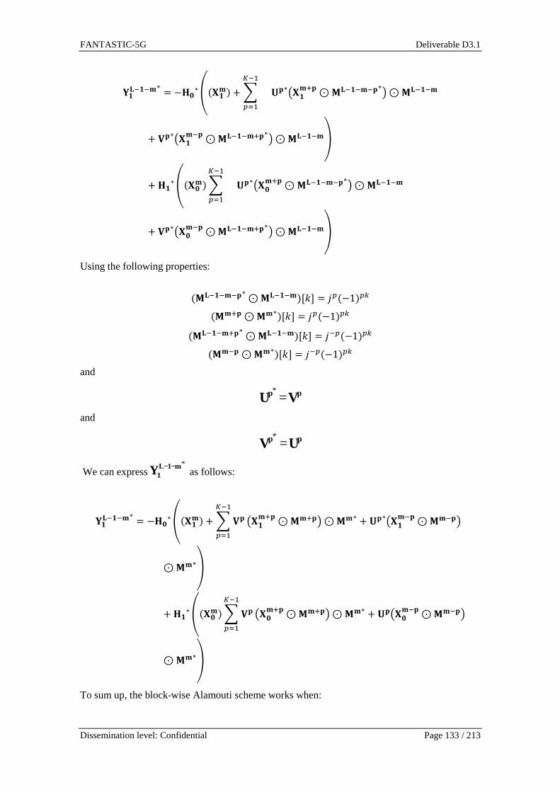
FANTASTIC-5G Deliverable D3.1
Dissemination level: Confidential Page 133 / 213
%�-L�L&∗ = −��∗ô;��&> + +PL_ `_ *+∗���&p+⊙(-L�L&L+∗�⊙(-L�L&+ ,+∗���&L+⊙(-L�L&p+∗�⊙(-L�L&÷+��∗ô;��&>+PL_ `_ *+∗���&p+⊙(-L�L&L+∗�⊙(-L�L&+ ,+∗���&L+⊙(-L�L&p+∗�⊙(-L�L&÷
Using the following properties:
;(-L�L&L+∗⊙(-L�L&>#9% = 7 ;−1> - ;(&p+⊙(&∗>#9% = 7 ;−1> - ;(-L�L&p+∗⊙(-L�L&>#9% = 7L ;−1> - ;(&L+⊙(&∗>#9% = 7L ;−1> -
and
pp VU =*
and
pp UV =*
We can express*m1L
1Y −− as follows:
%�-L�L&∗ = −��∗ô;��&> + + ,+PL_ `_ ���&p+⊙(&p+�⊙(&∗ + *+∗���&L+⊙(&L+�
⊙(&∗÷+��∗ô;��&>+ ,+
PL_ `_ ���&p+⊙(&p+�⊙(&∗ + *+���&L+⊙(&L+�
⊙(&∗÷
To sum up, the block-wise Alamouti scheme works when:

FANTASTIC-5G Deliverable D3.1
Dissemination level: Confidential Page 134 / 213
• Transmission blocks are isolated in time-direction by using guard periods in order to guarantee the orthogonality of the useful and interference terms
• The channel is constant in time-direction over two blocks
• The frequency selectivity of the channel is low; flat fading channel.
The block diagram of the receiver is depicted in Figure 6-58.
Figure 6-58 Block diagram of the receiver for a blo ck-wise Alamouti 2x1 scheme. TR
stands for time reversal.
The aim of the next section is to demonstrate how the block-wise Alamouti scheme can be adapted to FS-FBMC based receiver.
6.4.1.1.4 Block-Wise Time reversal Alamouti scheme for FS-FBMC receiver
Principle
We start with the initial block-wise Alamouti scheme. The main idea is to combine the two received block after the FFT and before the filtering process. This strategy will give better performance when the frequency selectivity of the channel increases. The thm received vector after the FFT (and before the filtering process) can be expressed as:
%�& = +��ô�;��&⊙(&> + + .+PL_ `_ ���&L+⊙(&L+� + /+���&p+⊙(&p+�÷
+ ��ô�;��&⊙(&>+ .+PL_ `_ ���&L+⊙(&L+� + /+���&p+⊙(&p+�÷
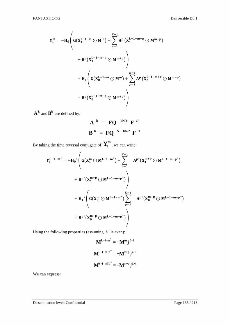
FANTASTIC-5G Deliverable D3.1
Dissemination level: Confidential Page 135 / 213
%�& = −��ô����-L�L&⊙(&� + + .+PL_ `_ ���-L�L&p+⊙(&L+�
+ /+���-L�L&L+⊙(&p+�÷+ ��ô����-L�L&⊙(&� + + .+
PL_ `_ ���-L�L&p+⊙(&L+�
+ /+���-L�L&L+⊙(&p+�÷
kA and kB are defined by:
HFFQA kN/2k =
HFFQB kN/2Nk −=
By taking the time reversal conjugate of m1Y , we can write:
%�-L�L&∗ = −��∗ô����&⊙(-L�L&∗� + +PL_ `_ .+∗���&p+⊙(-L�L&L+∗�+ /+∗���&L+⊙(-L�L&p+∗�÷+ ��∗ô����&⊙(-L�L&∗�+PL_ `_ .+∗���&p+⊙(-L�L&L+∗�+ /+∗���&L+⊙(-L�L&p+∗�÷
Using the following properties (assuming is even):
1*= −−− − Ljmm1L MM
1*= −+−−− − Ljpmpm1L MM
1*= −−+−− − Ljpmpm1L MM
We can express:
L

FANTASTIC-5G Deliverable D3.1
Dissemination level: Confidential Page 136 / 213
%�-L�L&∗ = ��∗7XL_;�;��&⊙(&> + +;.+∗;��&p+⊙(&p+> +PL_ `_ /+∗;��&L+⊙(&L+>>>
− ��∗7XL_;�;��&⊙(&> + +;.+∗;��&p+⊙(&p+> +PL_ `_ /+∗;��&L+
⊙(&L+>>> Eventually, since:
pp BA =*
and
pp AB =*
It is possible to adapt the Alamouti scheme to a FS-FBMC based receiver by applying the follwing linear transform:
*1*0 )(ˆ m1L
1100 YHYHX −−−+∝ Lm j
*1*1 )(ˆ m1L
1001 YHYHX −−−−∝ Lm j
The proposed receiver architecture is depicted in Figure 6-59.
Figure 6-59 Block diagram of the receiver based on FS-FBMC principle for a block-wise
2x 1 Alamouti scheme. TR stands for time reversal. α is equal to .
The difference between the PPN receiver and the proposed one stems from, first the structure of the equalizer, and secondly from the correction factor necessary to guarantee the orthogonality in case of FS-FBMC base receiver.
Frame structure
In the previous subsection, we have derived a particular structure of the receiver for the coding matrix of [RIS10]. Based on the previous results, this coding matrix can be modified as follows:
−−− −− TXTX
XX
01
1011 )()( LL jj
In that case, the correction factor of the FS-FBMC based receiver α is equal to 1.
1)( −Lj

FANTASTIC-5G Deliverable D3.1
Dissemination level: Confidential Page 137 / 213
In the proposed scheme, guard period should be inserted to maintain the symmetry required by the Alamouti block-wise scheme. In case of burst transmission with a preamble, it is possible to relax this constraint. Indeed, when a preamble is transmitted, the receiver knows exactly the sequence and therefore the interference generated on payload symbol. If the channel is perfectly known a simple interference cancellation scheme is sufficient to maintain the symmetry required by the Alamouti block-wise scheme. The proposed frame format is illustrated in Figure 6-60.
Figure 6-60 Proposed Alamouti block-wise format.
The block diagram of the corresponding receiver including the interference cancellation block is depicted in Figure 6-61.
Figure 6-61 Proposed receiver based on FS-FBMC stra tegy with preamble interference
cancellation (2x1 configuration).
6.4.1.1.5 Simulations results
System model
For the numerical evaluation of the proposed scheme, the channels between the transmit antennas and the receiver are modeled by the following two transfer functions (from [Bel08]): üa;0> = 1 \ 0.50L_ � 0.30LA
ü_;0> � 1 � 1.50L_ � 0.90LA As depicted in Figure 6-62 when a channel is low-pass the other one is high pass. The size of the FFT is set to N from 16 to 256. The PHYDYAS K=3 and K=4 prototype filters are considered.

FANTASTIC-5G Deliverable D3.1
Dissemination level: Confidential Page 138 / 213
Figure 6-62 Normalized magnitude of the theoretical channels considered for the
performance evaluation.
Results
First we propose to compare the two receivers’ architectures for various size of FFT from 16 to 256. By increasing the FFT size (decreasing the intercarrier spacing), the selectivity of the channel is decreased. The Mean Square error (MSE) on received complex symbols is estimated using Monte-Carlo simulations. No noise is added to the signal and a perfect knowledge of the channel coefficients are assumed. Each coded blocks are spaced by a block of null samples to ensure the perfect orthogonality. The performances are depicted in Figure 6-63.
Figure 6-63 Comparison of two receiver strategies a s a function of the FFT size.
The results clearly demonstrate the advantage of the receiver based on FS-FBMC principle. When the ratio of channel delay spread over the FFT size decreases, the performance of a PPN receiver tends to the one of the proposed receiver. On the contrary if the ratio is small, the performance of the PPN receiver is quite bad. FS-FBMC based receiver keeps good performance even with a "large" ratio of channel delay spread over the FFT size. This result has also been demonstrated for single input single output (SISO) channel in [DBC+14].

FANTASTIC-5G Deliverable D3.1
Dissemination level: Confidential Page 139 / 213
We have also investigated the impact of reducing the guard time between two coded blocks. Some results are depicted in Figure 6-64. We have analyzed the impact of the interference on the MSE for each FBMC symbols when the two blocks are overlapped with ε samples. When
/27= Nε the MSE is equal to 5dB for the last symbol for the two receivers (PPN and FS FBMC based). In that case the level of interference is too high for a correct decoding, especially for high order modulations. When /25= Nε the RMSE is then equal to 28dB. This level of interference could be negligible compared to thermal noise when QPSK, 16-QAM or even 64-QAM modulations are used. This configuration allows decreasing the loss of efficiency while maintaining acceptable performance. Of course solution based on time interleaving combined with an appropriate forward error correction scheme is also possible to lower the effect of the interference at the edges of the block.
Figure 6-64 Effect of the overlapping between conse cutive coded blocks on RMSE.
6.4.2 P-OFDM performance in supporting MIMO For a MIMO-BICM system with practical modulator/demodulator, the bitwise mutual information (MI) of the equivalent modulation channel is served as the code-independent performance measure [FJM12]. Assuming a practical finite-length interleaver and the specific demodulator are used, herein we use 1%-outage MI as performance metric, which denotes the maximum achievable rate for non-ergodic fading channels.

FANTASTIC-5G Deliverable D3.1
Dissemination level: Confidential Page 140 / 213
Figure 6-65 Outage mutual information of SFBC/Alamo uti (2x1 MISO, ETU channel).
For the performance evaluation of transmit diversity techniques, space-frequency block coding (SFBC) scheme with two transmit antennas and one receive antenna is applied. The resource mapping is the same as used in LTE. The 1%-outage MI performance of SFBC/Alamouti for 3GPP ETU channels is evaluated in Figure 6-65. The solid lines indicate the performance from applying perfect channel estimation, while the dash lines showing the performance with LS based channel estimation. P-OFDM aims at achieving comparable performance compared to CP-OFDM in this scenario with low-mobility and synchronous transmission. As shown in the figure, P-OFDM can directly apply this transmit diversity technique and achieves marginal gain over conventional CP-OFDM. Applying spatial multiplexing techniques means different antenna ports transmit different data streams. At the receiver side, different demodulators can be implemented to achieve a trade-off between performance and complexity. For the illustration purpose, near-ML detection like sphere detection (SD) is exploited here. We remark that the results hold for other categories of receivers, e.g., linear MMSE receiver or enhanced non-linear receiver. One of the favorable features of the proposed P-OFDM system is its good localization in time and frequency domain, which is guaranteed by the pulse shape design. Such feature allows the robustness in asynchronous transmission. For the fairness of comparison, we evaluate the MI performance in both synchronous and asynchronous scenarios. Specifically, we assume a 4x4 MIMO system (without antenna correlation) is transmitting 4-layer streams in ETU channels with 3 km/h. The SD is applied at the receiver. The solid lines indicate the performance from applying perfect channel estimation, while the dash lines showing the performance with LS based channel estimation. Figure 6-66 and Figure 6-67 depict 1% outage MI performance for synchronous transmissions and asynchronous transmission, respectively. The robustness to timing misalignment for FBMC/QAM systems is validated.

FANTASTIC-5G Deliverable D3.1
Dissemination level: Confidential Page 141 / 213
Figure 6-66 Outage mutual information of spatial mu ltiplexing (4x4 MIMO, ETU channel, synchronous transmission).
Figure 6-67 Outage mutual information of spatial mu ltiplexing (4x4 MIMO, ETU channel, asynchronous transmission).
6.4.3 MIMO for connected vehicles As explained in section 3.1.2, there is an opportunity to design new waveforms (such as the FC-OFDM) which are configurable per block of frequency and can support various services simultaneously. Additionally, we believe that the way multiple antennas are used needs also to to be configurable per service. In this sub-section, we investigate the use of the predictor antenna in MISO and MIMO systems to lower the cost in power and spectrum of fast moving connected vehicles; adaptation of this work for FC-OFDM is FFS.
During METIS project, the link between the 5G network and fast moving connected vehicles (equipped with at least one antenna on the roof) has been studied. It was shown that adaptive MIMO techniques are not robust to speed. New ‘Channel prediction’ techniques were introduced to solve this issue and make adaptive antennas work for very fast moving vehicles.
More precisely, Time division duplex (TDD) mode was assumed. Delayed channel state information at the transmission side was used to perform maximum ratio transmission (MRT) beamforming towards the connected vehicle. Large multiple input single output (MISO) was considered (with 64 antennas at the base station). Due to the speed of the vehicle, beamforming mis-pointing occurred. Three channel prediction techniques to reduce the mis-pointing effect were studied [PSS15]:
• Separate Receive and Training Antenna (SRTA); • SRTA with Border Switch Off Schemes (SRTA-BSOS); • The Polynomial Interpolation SRTA (SRTA-PI).
They were compared to a Reference System (RS) without channel prediction.
Figure 6-68illustrates the four schemes studied during METIS project: RS, SRTA, SRTA-BSOS and SRTA-PI. Figure 6-68-a) shows that RS suffers from beamforming mis-pointing due to delayed channel state information at the transmitter side. Figure 6-68-b) shows that SRTA reduces mis-pointing by exploiting a predictor antenna, selecting a receive antenna (among several candidates) and adapting the TDD frame length (by steps of 1ms) depending on the speed. When the selected receive antenna and the selected frame duration does not perfectly match the current speed, there is some residual mis-pointing. Figure 6-68-c) shows that SRTA-BSOS switches off border antennas of the base station to increase the side lobes of the focused signal and to reduce the effect of mis-pointing. Figure 6-68-d) shows that SRTA-PI exploits multiple predictor

FANTASTIC-5G Deliverable D3.1
Dissemination level: Confidential Page 142 / 213
antennas and multiple measurements to interpolate the channel estimate and perfectly predict the channel: mis-pointing is suppressed
Figure 6-68 Figure extracted from [MET15-D3.3] illu strating the four schemes studied during METIS project.
The SRTA-PI scheme was identified as ‘Most Promising Technical Approach’ (MPTA) for 5G during METIS project [MET15-D3.3]. For further information on the MPTA, please refer to [PSS15].
In this deliverable, we pursue the following two new objectives:
1) to evaluate the cost in power (at the network side) of the support of fast moving connected vehicles (with and without channel prediction);
2) to evaluate the cost in spectrum (at the network side) of the support of fast moving connected vehicles (with and without channel prediction).
This evaluation is performed under the following constrain: a target QoS is guaranteed for all speeds.
Indeed, this study aims at quantifying how much less power/spectrum is needed, thanks to channel prediction, to support fast moving connected vehicles with the same QoS, whatever their speed.
6.4.3.1 Cost in transmit power of fast moving conne cted vehicles
The objective of this sub-section is to compare the cost in transmit (i.e. radiated) power (at the network side), when the base station transmits data towards a connected vehicle with one of the four following scenarios:
• ‘RD scenario’: 1x5 Rx Diversity (RD) (with 5 receive antennas); • ‘RS scenario’: MRT MISO transmission with RS (no prediction); • ‘SRTA scenario’: MRT MISO transmission with SRTA (simple prediction); • ‘PP scenario’: MRT MISO transmission with perfect prediction (PP), as attainable in
practice with SRTA-PI.
For MRT MISO transmission schemes, various numbers of transmit antennas are considered: 8, 16, 32, 64, 128 and 256.

FANTASTIC-5G Deliverable D3.1
Dissemination level: Confidential Page 143 / 213
Figure 6-69 below provides simulation results obtained for ‘RD scenario’, ‘RS scenario’, ‘SRTA scenario’ and ‘PP scenario’. Regarding ‘RS scenario’, ‘SRTA scenario’ and ‘PP scenario’, the simulation assumptions and methodology described in [PSS15] and [MET15-D3.3] are used:
• 64QAM and a coding rate of ¾ is assumed; • an open loop power control is applied. It calculates the exact transmit power to meet 0.1%
BLER at the initial transmission for 64QAM, based on the predicted channel. As a consequence, due to channel aging, the attained BLER is degraded with speed. For large numbers of transmit antennas, the MRT MISO beam is narrower, the mis-pointing effect more severe and the attained BLER worse.
Regarding, ‘RD scenario’, an open loop power control is also used. However, the power control loop for RD adds a 6dB power boost to the target SNR (the one required for 0.1% BLER at the initial transmission for 64QAM). According to our simulations this margin limits the mismatch between the predicted SNR and the actual SNR. As illustrated in Figure 6-69, it ensures that the attained BLER with RD (‘reference’ curve) is below 10% for all speeds below 300km/h.
Figure 6-69 Attained BLER versus speed for RS, SRTA and PP, considering a large MISO beamforming system using 8, 16, 32, 64, 64 or 128 t ransmit antennas at the base station side. The ‘Reference’ curve corresponds to RD.
The curves in Figure 6-69 only show the degradation of QoS due to speed, for various schemes. One can observe that whatever the number of transmit antennas, the RS scheme cannot guarantee a BLER for all speeds. In practice, the network has to guarantee a given QoS.
In practice, for RS, the network would switch from RS to RD, at a given speed threshold to guarantee a certain QoS. For SRTA, the base station would use SRTA in some regions of speed and would fall back to RD in others, to maintain the initial BLER below a given target. In some regions, the number of transmit antennas for SRTA would be adapted to reach the target. As we believe that due to this QoS guarantying mechanism, the network would ‘de-activate’ MRT MISO beamforming and would therefore spend more power. To evaluate this cost in power, we propose the following evaluation methodology:
• we keep the target 0.1% BLER at initial transmission as a target for the open loop power control (for the RS, SRTA and PP schemes);
• we defined a target maximum BLER (10% at initial transmission for instance), which must not be exceeded even at high velocities;

FANTASTIC-5G Deliverable D3.1
Dissemination level: Confidential Page 144 / 213
• we add a basic QoS mechanism guarantying that the attained BLER is bounded by the target maximum BLER: the base station adapts the number of transmit antennas. If it is not enough, it falls back to RD;
• we evaluate the corresponding spent (transmission) power: the ratio between the instantaneous power spent at the base station (for a given fast fading sample) and the power that would be spent with RD (for the exact same fading sample).
With this methodology, the attained BLER is bounded by 10%, even with mis-pointing.
Figure 6-70 illustrates the corresponding ratio measured between the power spent at the base station and the power that would be spent with RD. Without channel prediction (‘MRT-RS’ curve) the system falls back to RD at very low speed. RD being the reference in terms of spent power, the ratio attains 0dB. Thanks to channel prediction (‘MRT-SRTA’ curve), the system can spend much less power (almost 30dB less) than RD for all speeds below 50 km/h. For higher speeds, a more sophisticated prediction (‘PP’ curve) is needed.
Figure 6-70 Ratio of power spent by large MISO BF u sing RS/SRTA/PP over power spent for RD, when BLER is controlled by adapting the num ber of transmit antennas and falling back to RD when necessary.
The attained BLER is bounded by 10%, even with mis-pointing, as illustrated in Figure 6-71.
Figure 6-71 Attained BLER with MRT MISO RS, MRT MIS O SRTA, and MRT MISO PP, when adaptation of the number of transmit antennas and f all back to RD is applied to avoid exceeding 10% BLER.

FANTASTIC-5G Deliverable D3.1
Dissemination level: Confidential Page 145 / 213
6.4.3.2 Cost in spectrum of fast moving connected v ehicles
In this current deliverable, we apply the channel prediction technique described in [PSS15] to spatial multiplexing MIMO. Zero forcing (ZF) is considered. Figure 6-72 illustrates the RS and SRTA schemes for a 256x5 ZF MIMO system. On the left hand side of the figure, the data stream intended to the last antenna of the vehicle ‘misses its target’ and the zeros of interference are misplaced in space, resulting in un-expected interference. On the right hand side of the figure, the TDD frame length is adapted (by steps of 1ms) to reduce the mis-pointing
Figure 6-72 Radiated power of one data stream (amon g 5) of a 256x5ZF MIMO system, without (vehicle on the left) and with (vehicle on the right) channel prediction.
The objective of this sub-section is to compare the cost in spectrum at the network side, when the base station transmits data towards a connected vehicle with one of the four following scenarios:
• ‘RD scenario’: 1x5 Rx Diversity (with 5 receive antennas); • ‘RS scenario’: ZF MIMO with RS (no prediction); • ‘SRTA scenario’: ZFMIMO with SRTA (simple prediction); • ‘PP scenario’: ZF MIMO with perfect prediction.
ZF MIMO is implemented with various antenna configurations: 8 to 256 transmit antennas and 2 to 5 receive antennas.
Figure 6-73 and Figure 6-74 provide simulation results obtained for ZF MIMO with two and five receive antennas, respectively. The ‘reference’ curve gives the performance of the RD scheme already presented in the previous section. The simulation methodology described in [PSS15] and [MET15-D3.3] is used and extended for ZF-MIMO. Due to the mis-pointing effect, the attained BLER is degraded with speed. Also the larger is the number of data streams (i.e. the number of receive antennas) the more severe is the degradation. With such schemes the QoS cannot be guaranteed for all speeds.

FANTASTIC-5G Deliverable D3.1
Dissemination level: Confidential Page 146 / 213
Figure 6-73 Attained BLER when adaptation of the nu mber of the number of data streams and fallback to RD is applied to avoid exceeding 10 % BLER.
Figure 6-74 BLER vs speed curves for ZF MIMO using RS, SRTA and PP for 8 to 256
transmit antennas 5 receive antennas (i.e. data str eams). The ‘Reference’ curve is for RD.
In practice, the network has to guarantee a given QoS. It would therefore switch from RS (or SRTA) to RD, at a given speed threshold to guarantee a certain QoS. The number of data streams would be adapted to reach the target. Due to this QoS guarantying mechanism, the network would spend more spectrum to connect fast moving vehicles with the same data rate and the same QoS. To evaluate this cost in spectrum, we propose the following evaluation methodology:
• we keep the target 0.1% BLER at initial transmission as a target for the open loop power control (for the RS, SRTA and PP schemes);
• we defined a target maximum BLER(10% at initial transmission for instance), due to speed;

FANTASTIC-5G Deliverable D3.1
Dissemination level: Confidential Page 147 / 213
• we add a QoS mechanism guarantying that the attained BLER is bounded by the target maximum BLER: the base station adapts the number of transmit antennas. If it is not enough, it falls back to RD;
• we evaluate the corresponding spent spectrum: the ratio between the spectrum spent with MIMO and the power that would be spent with RD. This ratio is the inverse of the number of receive antennas (therefore it takes the following values: 1, ½, 1/3, ¼ or 1/5).
With this methodology, the attained BLER is bounded by 10%, even with mis-pointing.
Figure 6-75 illustrates the corresponding ratio measured between the spectrum spent with MIMO and the power that would be spent with RD. Without channel prediction (‘ZF-RS’ curve), the system falls back to RD at extremely low speed. RD being the reference in terms of spent spectrum, the ratio attains 1. Thanks to channel prediction (SRTA), the system can spend much less spectrum (5 times less) than RD for all speeds up to 10 km/h. For higher speeds, a more sophisticated prediction is needed.
Figure 6-75 Ratio of spectrum spent by ZF MIMO usin g RS/SRTA/PP over spectrum spent by RD, when BLER is controlled by adapting the numb er of data streams and falling back to RD when necessary.
6.4.3.3 Conclusion
This study provides two initial conclusions:
• With a basic channel prediction (SRTA), the network can guaranty the QoS (10% BLER at initial transmission) of a connected vehicle moving at up to 50 km/h, with almost 30dB less power than without channel prediction;
• With a basic channel prediction (SRTA), the network can guaranty the QoS (10% BLER at initial transmission) of a connected vehicle moving at up to 10 km/h, with almost 5 times less spectrum than without channel prediction.
It is FFS whether this 50 km/h and 10 km/h thresholsd are valid for higher power saving or spectrum saving values than the one simulated up to now. This study is performed assuming OFDM. Adaptation to FD-OFDM or other new waveforms optimised for high velocities, is FFS.

FANTASTIC-5G Deliverable D3.1
Dissemination level: Confidential Page 148 / 213
6.5 Service driven frame design
6.5.1 Frame design for enabling efficient multi-service support At first glance the high degree of configurability described in the main body section 2.5.1 appears to overcomplicate the system (e.g. scheduling). So, we need to introduce means to ease these functionalities. One key element to do so is the so-called tiling concept as indicated by Figure 6-76.
Figure 6-76 Example illustration of the tiling conc ept with two different tiles (blue and
purple), each carrying different TTI lengths (e.g. 1 ms and 0.25 ms).
We have two basic sub-tiles:
- A wide-band (e.g. 720 kHz) but short-timed sub-tile (e.g. 1/4 ms) – shown in purple - A narrow-band (e.g. 180 kHz) but long-timed sub-tile (e.g. 1 ms) – shown in light blue.
Both sub-tiles contain the same number of resource elements (168) and multiple sub-tiles can be attached together to form a so-called tile having the dimensions 720 kHz and 1 ms in both cases. The tiling concept handles frequency multiplexing of different TTI lengths (typically in conjunction with different co-existing numerologies). For keeping overhead constant and code block sizes not too small, shorter (in time) sub-tiles are typically broader in frequency. The tile is the resource-organizing unit for coping with different sub-tile shapes. An appropriate scheduler solution should first allocate the tiles according to current service and propagation demands (on a 1 ms or larger timescale) and then carry out the actual resource block scheduling using the sub-tiles. In addition to this the scheduler needs to be allowed to instantly reassign resources originally being assigned for e.g. broadband traffic to urgent low-latency transmissions either by allowing the low-latency transmission to use those resources with respective higher transmission power to drown the broadband transmission (in case of UL transmission) or by puncturing the broadband transmission (in case of DL transmission). This is visualized in Figure 6-77. Naturally, the broadband transmission suffers from either very strong interference (case 1) or missing data (case 2). To cope with this retransmission concepts (e.g. HARQ) are required.

FANTASTIC-5G Deliverable D3.1
Dissemination level: Confidential Page 149 / 213
Figure 6-77 Preemption (or “hijacking”) of resource usage for the tiling concept in case
of urgent low latency transmission.
Longer transmission periods (e.g. for MBS and eMBB services) can be achieved by sub-tile/tile bundling (e.g. for high velocity (but without low latency requirement) cases: Multiple short sub-tiles (0.25 ms) with increased subcarrier spacing are combined for improved channel estimation.
Another relevant aspect frame design has to care for is the set of numerologies to be applied. The following table provides the numerology set with 15 kHz basis, 20 MHz bandwidth, sampling rate 30.72 Msamples/s:
Table 6-12 Numerology sets (with options for large cells)
TTI lengh: 0.25 ms 0.25 ms (large cells)
0.125 ms 0.125 ms (large cells)
1 ms (LTE like)
2 ms (MMC, BMS)
Subcarrier spacing:
30 kHz 15 kHz 60 kHz 30 kHz 15 kHz 3,75 kHz
#symbols/ TTI: 7 3 7 3 14 7 #samples/symbol: 1024+G 2048+G 512+G 1024+G 2048+G 8192+G Guard time (overhead):
2,38µs (G = 73) (6,6%)
16,6µs (G = 512)
(20%)
1,17µs (G = 36) (6,6%)
8,3µs (G = 256)
(20%)
4,76µs (G = 146) (6,6%)
19 µs (G = 584) (6,6%)
Non-large cell parameter sets with SC-FDMA may use user-specific ZT-DFTs [BTS+13] for additional multi-path delay spread protection (preferred case instead of “large cell” parameter set), regarding the problem which is addressed in section 2.1.1.5.
The set of optionally supported bandwidths are given in the following table. In green the main cases are highlighted. Ultimately the number of options has to be condensed:

FANTASTIC-5G Deliverable D3.1
Dissemination level: Confidential Page 150 / 213
Table 6-13 Supported bandwidths.
Bandwidth (MHz):
0.2 0.7 1.4 3 5 10 20 40 80 160 320
Sampling rate (Msamples/s): 0.48 0.96 1.92 3.84 7.68 15.36 30.72 61.44 122.88 245.88 491.52
FFT size (15 kHz):
32 64 128 256 512 1024 2048 4096 8192 16384 32768
FFT size (30 kHz):
n/a 32 64 128 256 512 1024 2048 4096 8192 16384
FFT size (60 kHz):
n/a n/a 32 64 128 256 512 1024 2048 4096 8192
6.5.2 Integrated frame design to support multiple s ervices
6.5.2.1 Service specific resource partitions
Due to the widely deployment of LTE network, OFDM like multi-carrier (MC) waveform continues to be a strong candidate for the 5G system. The radio resources in the MC system are typically organized in terms of time-frequency resource grids. The radio resources in the proposed integrated 5G RAT are divided into different resource partitions, each of which targets at particular service and can be characterized by a set of physical layer parameters such as TTI length, subcarrier spacing, waveform, time-frequency resource allocations and partition specific number of antenna ports etc. For example, the integrated resource map contains several resource partitions as illustrated in Figure 6-78.
Figure 6-78 Radio resource map of multiple resource partitions.
As shown in Figure 6-78, the radio resource map includes several resource partitions, and each partition is designed for certain service. For example, partition (Part.) 1 can be used for the legacy UEs with conventional voice and data services offered by the current LTE. And it is assumed that Part. 1 can be used for normal radio control plane functions such as RRC connection management and security authentication etc. Other partitions are defined to support service specific user plane data traffic. For instance, Parts. 2 and 3 may be designed for extremely broadband service with very low latency requirements. Parts. 4, 5 and 6 are tailored for other services like MMC, MCC and V2X, respectively.
It should be noted that these resource partitions can be non-overlapped (Parts 1, 2 and 3), partially overlapped (Part. 5 and Parts. 2 and 3), or fully overlapped (Part. 4 and Part. 2,

FANTASTIC-5G Deliverable D3.1
Dissemination level: Confidential Page 151 / 213
and Part. 6 and Part. 1) with each other. One practical scenario of fully overlapped resource partitions can be: several narrow band MMC resource partitions are fully embedded in the wideband primary resource partition. Such flexible resource partitions enable all kinds of possible coexistence of different services. The dimension and position of each service partition can be allocated anywhere in the radio resource map according to resource optimization criteria.
Some resource partitions can only operate in a non-standalone manner in the sense that the UEs of these partitions first establish the RRC connection with the network by employing the control plane partition (Part. 1 in Figure 6-78) and only access to non-standalone partitions for the sake of service-specific data transportation. For instance, those MBB partitions in high frequency band and MCC partitions can operate in non-standalone manner. In contrast to those non-standalone resource partitions, some resource partitions can operate in standalone manner. These standalone resource partitions shall support data service as well as control plane functions such as cell search, system information broadcast and RRC connection establishment procedure etc.
To support energy efficient communication, different resource partitions can be turned on and off according to the actual traffic needs. Specifically, the standalone resource partitions may transmit some partition-specific discovery signal which enables the UEs of interest to perform the RRM measurements of the respective resource partition.
6.5.2.2 Extended resource block definitions
To support different throughput, latency and reliability targets, it is required to have all supported radio resource formats defined in the standard. For example, the set of supported TTIs can be {0.2ms, 1ms, 2ms, 4ms}, and set of subcarrier spacing can be {3.75 kHz, 7.5 kHz, 15 kHz, 75 kHz, 750 kHz, 1.5MHz}. The small subcarrier spacing such as 3.75 kHz and 7.5 kHz are mainly used for the MTC with low bandwidth and low power consumption needs. And the large subcarrier spacing such as 750 kHz and 1.5 MHz can be mainly considered for the high frequency band, i.e., above 30GHz.
The radio resource block (RB) is defined as the minimum resource allocation unit. Assuming OFDM-like waveform where one time-frequency symbol is termed as resource element, the following resource block definitions to support different TTIs and subcarrier spacing are defined in Table 6-14 to Table 6-20.
It should be noted that these tables may be extended or amended to include more information such as CP length and other supported waveforms etc.
Table 6-14 Resource block type 1, legacy MBB, low f req. band, normal latency (TTI of 1ms)
Subcarrier spacing 15kHz
TTI 1ms
Number of OFDM symbols per TTI 14
Number of subcarriers per RB 12
Bandwidth per RB 180KHz
Number of resource elements (REs) per RB 168 = 12x14
Table 6-15 Resource block type 2, MCC/V2X, low freq . band, low latency (TTI of 0.2ms)
Subcarrier spacing 15kHz

FANTASTIC-5G Deliverable D3.1
Dissemination level: Confidential Page 152 / 213
TTI 0.2ms
Number of OFDM symbols per TTI 2
Number of subcarriers per resource block 72
Bandwidth per RB 1080KHz
Number of REs per RB 144 = 72x2
Table 6-16 Resource block type 3, MBB/MCC/V2X, low to mid freq. band, low latency (TTI of 0.2ms)
Subcarrier spacing 75kHz
TTI 0.2ms
Number of OFDM symbols per TTI 14
Number of subcarriers per resource block 12
Bandwidth per RB 900KHz
Number of REs per RB 168 = 12x14
Table 6-17 Resource block type 4, MBB, high freq. b and, low latency (TTI of 20us)
Subcarrier spacing 750kHz
TTI 20us
Number of OFDM symbols per TTI 14
Number of subcarriers per resource block 12
Bandwidth per RB 9MHz
Number of REs per RB 168 = 12x14
Table 6-18 Resource block type 5, MBB, high freq. b and, low latency (TTI of 10us)
Subcarrier spacing 1500kHz
TTI 10us
Number of OFDM symbols per TTI 14
Number of subcarriers per resource block 12
Bandwidth per RB 18MHz
Number of REs per RB 168 = 12x14
Table 6-19 Resource block type 6, MMC, low cost (TT I of 2ms)
Subcarrier spacing 7.5kHz

FANTASTIC-5G Deliverable D3.1
Dissemination level: Confidential Page 153 / 213
TTI 2ms
Number of OFDM symbols per TTI 14
Number of subcarriers per resource block 12
Bandwidth per RB 90KHz
Number of REs per RB 168 = 12x14
Table 6-20 Resource block type 7, MMC, low cost (TT I of 4ms)
Subcarrier spacing 3.75kHz
TTI 4ms
Number of OFDM symbols per TTI 14
Number of subcarriers per resource block 12
Bandwidth per RB 36KHz
Number of REs per RB 168 = 12x14
6.5.2.3 Extended DMRS Pattern
Each resource block requires some embedded demodulation reference signal (DMRS) to enable the channel estimation for coherent demodulation of the transmitted control and data signal. For the above RB definition types 1, 3 to 7, the existing DMRS pattern in LTE can be reused. However, the RB type-2 definition has different dimension than the current LTE RB, as such the following DMRS pattern thereof can be applied.

FANTASTIC-5G Deliverable D3.1
Dissemination level: Confidential Page 154 / 213
Figure 6-79 Resource block type 2 definition and DM RS patterns.
The REs in blue in Figure 6-79 show the placement of DMRS in the RB. The DMRS signal sequence generation method in LTE can be extended to this case as well.
6.5.3 Frame design based on service requirements Among the main objectives of a new 5G air interface should be its flexibility to be adapted to the diverse requirements stemming from the heterogeneous service demands that are posed nowadays. This diversity of requirements creates a very challenging environment in terms of service-specific KPIs and channel characteristics as it should be flexible enough to satisfy these needs while in parallel optimize the resource utilization and minimize the overhead introduced by the multi-service support functionalities/mechanisms. The 5G services are foreseen to include mobile broadband (MBB) services, supporting high data rates and high coverage, massive machine communication (MMC) services, supporting small packet sizes and infrequent transmissions, mission critical communication (MCC) services, with strict delay bounds and reliability indicators, and vehicular-to-anything communication (V2X) services, supporting both BS-to-device and device-to-device transmissions.

FANTASTIC-5G Deliverable D3.1
Dissemination level: Confidential Page 155 / 213
The current status of a stiff frame structure with e.g. a fixed transmission time interval (TTI) value, either cannot satisfy the extremely strict requirements of specific services (e.g. delay requirements of MCC services) or is resulting to underutilization and waste of resources due to inefficient resource management. Therefore, a flexible frame structure supporting the coexistence or multiplexing of different services is more than necessary in order to accomplish these diverse service requirements. We propose two methods for flexible frame structure design:
• Design based on 2N scaling of LTE settings: This method is exemplified by the TTI scaling. We define a set of TTI durations, where each duration is a double of the previous one (except for the smallest one).
• Design based on service classification: This method is exemplified in two cases. First, we show how this design principle applies to several parameters for one fixed service (V2V). Second, we apply this method to define a specific parameter (TTI value) for a set of services. We remark that this design does not necessarily indicate that different services require different frame designs, but rather the frame design should follow diverse assumptions, requirements, and scenario characteristics of different services.
To exemplify the first method 2N scaling, we apply it to define the minimum and maximum TTI length that a set of TTI lengths is generated based on the 2N approach. The motivation of introducing a flexible TTI supporting different TTI durations is as follows: it will both accomplish ultra-low latency capabilities (e.g. in case of MCC services) by facilitating short TTI durations and high spectral efficiency gains (e.g. in case of MBB services) by utilizing long TTI durations. The selection of TTI scaling, which is the set of available TTI values, is of high importance, because it directly affects the effectiveness of the proposed flexible frame structure solution.
For the 5G services mentioned above, reasonable values of TTI duration can be between 0.125ms and 4ms, therefore the generated TTI values belong to the set (0.125ms, 0.25ms, 0.5ms, 1ms, 2ms, 4ms). This approach is graphically depicted in Figure 6-80.
Figure 6-80 Flexible TTI - TTI Scaling based on 2N scaling.
For the second method based on service classification, we first need to identify the assumptions and requirements for a set of predefined services (e.g. MBB, MMC, MCC, V2X), including
• the service requirement such as latency and reliability • channel characteristics • duplex mode such as FDD or TDD • traffic model (burst or continuous transmission, packet size, etc.) • supported link such as UL/DL/D2D/macro/small cells • MIMO support type that whether different transmission modes or M-MIMO are
considered
0.125 ms (e.g. MCC services)
0.25 ms (e.g. MCC services)
0.5 ms (e.g. V2V services)
1 ms (e.g. V2I, MBB services)
2 ms (e.g. MBB, MMC services)
4 ms (e.g. BMS services)

FANTASTIC-5G Deliverable D3.1
Dissemination level: Confidential Page 156 / 213
Based on clarification of the above assumptions, we then design the key parameters for frame structure, which include TTI length, UL/DL switching periods if applicable, control signaling types (UE or cell specific, scheduled or grant-free), reference signals, HARQ (retransmission intervals, retransmitted data including redundancy and repetition), and system specific signals such as broadcasting channels. For example, indicate values of TTI length are illustrated in Figure 6-80. Note that frame structure parameters can be further categorized into the channel-related parameters (like subcarrier spacing), or the service-specific ones (like TTI duration). For different use cases in one service, the channel-related parameters can be further adapted to channel statistics.
One example to exemplify this method is the frame design of V2V service for driving safety. To the best of our current knowledge, V2V service needs to fulfill end-to-end latency around 1ms, and guarantee the reliability up to 99.99%. The most likely duplex mode to be used is TDD. Considering the transmission of decentralized environmental notification message (DENM), the irregular signals are transmitted in a one-to-many manner with individual acknowledgement. V2V communication mainly focuses on D2D links with individual feedback. In addition, macro cell may assist the D2D transmission as a complementary. The usage of MIMO is open for further discussion. Based on the above assumptions, we propose the following key factors for the frame structure in V2V services
• TTI length is set to 0.2-0.5ms for the consideration of low latency • UL/DL switching periods are also around 0.2-0.5ms. • Due to the high reliability requirement, we suggest to use ca. 20% overhead for control
signaling and ca. 10% overhead for reference signals. The detailed deployment of control signals and reference signals need to be carefully designed according to specific channel characteristics and use case requirements. For the tradeoff of latency and reliability
• HARQ with up to two retransmissions is desirable. The system specific signals need to be designed upon the system duty cycles.
Furthermore, we have very different use cases/applications (CAM, DENM, video, etc.) in V2V service. Therefore, some channel-dependent parameters, e.g. waveform numerology, can be also adapted to the channel statistics.
In order to support newly-emerging services with diverse requirements, scalable numerology and scalable TTI in 5G frame structure are envisioned. For example, in order to guarantee low-latency transmission, the TTI duration can be shortened to sub-ms levels and apply a single-symbol TTI for self-contained transmission. For the service with relaxed latency requirement, scalable longer TTI length can be applied to reduce the reference signals and signaling overhead.
Another example to exemplify the service-classification based method is to consider a flexible TTI design for a set of services. Specifically, diverse services are analyzed based on their requirements in order for each service to estimate the TTI value that reflects best its characteristics, satisfy its requirements in terms of KPI values (e.g. average delay, max delay, and throughput) and minimize the system resource overhead. Then a set of TTI lengths are generated which are mapped to the aforementioned services or group of services. In Figure 6-81 an indicative set of TTI lengths is depicted based on an initial analysis and service classification. Each TTI length is mapped to one or several services.
Figure 6-81 Flexible TTI - TTI Scaling based on ser vice classification.
Regarding the comparison between the two scaling methods, the second method fits better to the service requirements as it is not restricted to only quantized 2N values of TTI length. However, in case of absent of resource partitions in the spectrum, because of the different multiplicity factors
0.2 ms (e.g. MCC services)
0.4 ms (e.g. MCC services)
0.6 ms (e.g. V2V services)
1 ms (e.g. V2I, MBB services)
4 ms (e.g. BMS services)
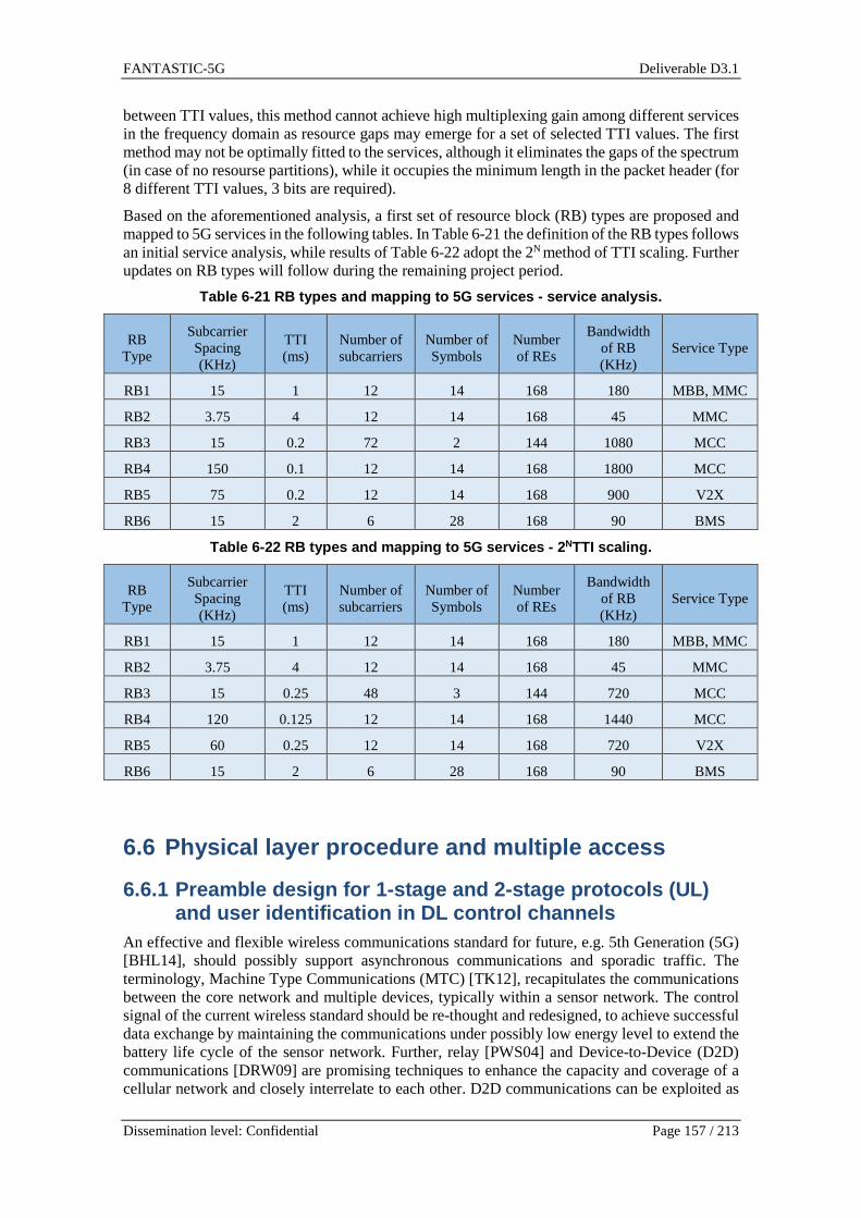
FANTASTIC-5G Deliverable D3.1
Dissemination level: Confidential Page 157 / 213
between TTI values, this method cannot achieve high multiplexing gain among different services in the frequency domain as resource gaps may emerge for a set of selected TTI values. The first method may not be optimally fitted to the services, although it eliminates the gaps of the spectrum (in case of no resourse partitions), while it occupies the minimum length in the packet header (for 8 different TTI values, 3 bits are required).
Based on the aforementioned analysis, a first set of resource block (RB) types are proposed and mapped to 5G services in the following tables. In Table 6-21 the definition of the RB types follows an initial service analysis, while results of Table 6-22 adopt the 2N method of TTI scaling. Further updates on RB types will follow during the remaining project period.
Table 6-21 RB types and mapping to 5G services - se rvice analysis.
RB Type
Subcarrier Spacing (KHz)
TTI (ms)
Number of subcarriers
Number of Symbols
Number of REs
Bandwidth of RB (KHz)
Service Type
RB1 15 1 12 14 168 180 MBB, MMC
RB2 3.75 4 12 14 168 45 MMC
RB3 15 0.2 72 2 144 1080 MCC
RB4 150 0.1 12 14 168 1800 MCC
RB5 75 0.2 12 14 168 900 V2X
RB6 15 2 6 28 168 90 BMS
Table 6-22 RB types and mapping to 5G services - 2 NTTI scaling.
RB Type
Subcarrier Spacing (KHz)
TTI (ms)
Number of subcarriers
Number of Symbols
Number of REs
Bandwidth of RB (KHz)
Service Type
RB1 15 1 12 14 168 180 MBB, MMC
RB2 3.75 4 12 14 168 45 MMC
RB3 15 0.25 48 3 144 720 MCC
RB4 120 0.125 12 14 168 1440 MCC
RB5 60 0.25 12 14 168 720 V2X
RB6 15 2 6 28 168 90 BMS
6.6 Physical layer procedure and multiple access
6.6.1 Preamble design for 1-stage and 2-stage proto cols (UL) and user identification in DL control channels
An effective and flexible wireless communications standard for future, e.g. 5th Generation (5G) [BHL14], should possibly support asynchronous communications and sporadic traffic. The terminology, Machine Type Communications (MTC) [TK12], recapitulates the communications between the core network and multiple devices, typically within a sensor network. The control signal of the current wireless standard should be re-thought and redesigned, to achieve successful data exchange by maintaining the communications under possibly low energy level to extend the battery life cycle of the sensor network. Further, relay [PWS04] and Device-to-Device (D2D) communications [DRW09] are promising techniques to enhance the capacity and coverage of a cellular network and closely interrelate to each other. D2D communications can be exploited as

FANTASTIC-5G Deliverable D3.1
Dissemination level: Confidential Page 158 / 213
an underlay for Long Term Evolution (LTE) and LTE-Advanced network. The corresponding signal processing, such as channel estimation, data detection and decoding, might suffer from relatively high interference of the conventional cellular system.
Thereby, we acknowledge that the low-power communications might be an important part of future 5G wireless communications. For the key 5G elements, such as MTC, relay and D2D, the devices need to identify, estimate, detect and decode the signal, with possibly low power and possibly not introduce unexpected interference to the marco cellular network. Hence, this motivates us to consider an achievable solution to enhance the control signal and data detection with low-power communications for 5G multicarrier system. Throughout this section, we consider the possible enhancement for random access procedure in current LTE standard [DPS11]. In Figure 6-82, a generic sketch for the concept is presented. We adopt the user-specific control signal, which is a pseudo preamble pattern. Especially, in order to support massive MTC, a large number of preamble patterns are required. For a given User Equipment (UE), the user-specific preamble is repeated through Physical Resource Blocks (PRBs), the user data is thus transmitted over data segments.
Figure 6-82 A generic sketch for the concept.
In this section, we investigate how to enable the UE to detect the activity and achieve a target false-alarm and misdetection probability even under relatively low Signal-to-Noise Ratio (SNR), identify the user-specific control signal and decode the user data signal.
6.6.1.1 Signal model
The random access procedure is described in [DPS11] for current LTE/LTE-Advanced wireless standard. In each cell, 64 preamble sequences are available, which serve as Physical Random Access Channel (PRACH). As 5G wireless communications could involve in more contention-based service and equipment. An enhanced random access procedure might be an issue, to support massive MTC and low-power communications. According to Fig. 1 as a candidate solution for 5G wireless, we assume that the PRACH-like control signal can be a preamble pattern, namely 12 QPSK modulated symbols within a PRB in5G multicarrier system. Although the preamble patterns are non-orthogonal any more, the number of the candidate preamble patterns becomes “massive”. We can sufficiently guarantee that the preamble pattern of a user is different from another user in the same cell. This allows us to denote the preamble pattern equivalently as a user ID signal. Obviously, we encounter a big challenge to identify the non-orthogonal user ID signal.
N

FANTASTIC-5G Deliverable D3.1
Dissemination level: Confidential Page 159 / 213
To increase the chance of successful detection, the user ID signal is repeated for N times, and the user data must be split into N segments consequently. The probability, in which a potential neighbor-cell interferer adopts the same user ID signal or a data sequence, might be low and negligible. It holds
02
124
≈
=N
P . (1)
For the n -th PRB, the system equation of the RT MM × MIMO communications can be
represented as
321
M
321
M
44444 344444 21L
MOMM
L
L
321
M
n
R
n
T
n
TRRR
T
T
n
R
TMn
Tn
Tn
TMn
Tn
Tn
MMnMnMn
Mnnn
Mnnn
TMn
Tn
Tn
hhh
hhh
hhh
ZXHY
z
z
z
x
x
x
y
y
y
+
⋅
=
,
2,
1,
,
2,
1,
,,2,,1,,
,2,2,2,1,2,
,1,2,1,1,1,
,
2,
1,
(2)
where the channel coefficient tr mmnh ,, of
TR MM × channel matrix obeys an independent and
identically distributed (i.i.d.) complex Gaussian distribution, i.e. )1,0(~,, CNtr mmnh , and it is
constant within an arbitrary considered PRB. An arbitrary vector in (2), e.g. rmn,y ,
tmn,x or rmn,z ,
is a 112 × vector, with respect to 12 QPSK symbols in a PRB. Furthermore, vector tmn,x can be
np as QPSK modulated preamble vector of n -th PRB, or tmn,d as QPSK modulated data vector
from unknown source. Vector rmn,z stands for the corresponding 112 × Additive White
Gaussian Noise (AWGN) vector. The definition of Signal-to-Noise Ratio (SNR) is given by
2100
10 2log10log10
σγ ss E
N
E == (3)
where 0N denotes the noise power density of AWGN and 2σ denotes the variance. Here the
energy per symbol is assumed 1=sE . Notice that the equation (3) is different from the
conventional definition of SNR in an MIMO system with transmit power constraint, in which the
definition of SNR terms out to be .
6.6.1.2 Detection and Estimation
At the rm -th RX antenna, the receive signal is
r
T
t
ttrr mn
M
mmimmnmi h ,
1,,,, zxy += ∑
=
. (4)
We define a threshold thE and let it compare to a metric A , which based on coherent detection.
Without any a priori knowledge, whether the preamble vector is transmitted or not, the false-
010log10
N
ME Ts=γ
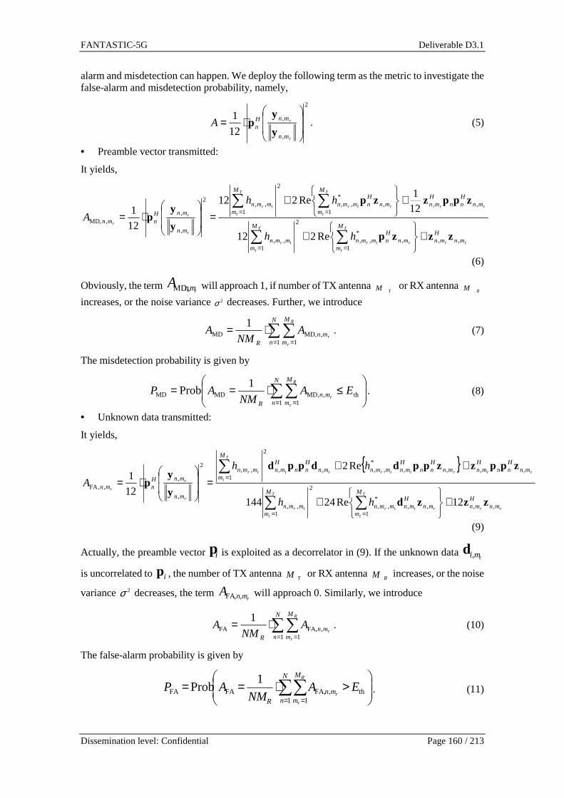
FANTASTIC-5G Deliverable D3.1
Dissemination level: Confidential Page 160 / 213
alarm and misdetection can happen. We deploy the following term as the metric to investigate the false-alarm and misdetection probability, namely,
2
,
,
12
1
⋅=
r
r
mn
mnHnA
y
yp . (5)
• Preamble vector transmitted:
It yields,
rr
T
t
rtr
T
t
tr
rr
T
t
rtr
T
t
tr
r
r
r
mnH
mn
M
mmn
Hnmmn
M
mmmn
mnHnn
Hmn
M
mmn
Hnmmn
M
mmmn
mn
mnHnmn
hh
hh
A
,,1
,*
,,
2
1,,
,,1
,*
,,
2
1,,
2
,
,,MD,
Re212
121
Re212
12
1
zzzp
zppzzp
y
yp
+
+
+
+=
⋅=
∑∑
∑∑
==
==
(6)
Obviously, the term rmnA ,MD, will approach 1, if number of TX antenna
TM or RX antenna RM
increases, or the noise variance 2σ decreases. Further, we introduce
∑∑= =
⋅=N
n
M
mmn
R
R
r
rA
NMA
1 1,MD,MD
1. (7)
The misdetection probability is given by
≤⋅== ∑∑
= =th
1 1,MD,MDMD
1Prob EA
NMAP
N
n
M
mmn
R
R
r
r. (8)
• Unknown data transmitted:
It yields,
{ }
rr
T
t
rttr
T
t
tr
rrrttrtt
T
t
tr
r
r
r
mnH
mn
M
mmn
Hmnmmn
M
mmmn
mnHnn
Hmnmn
Hnn
Hmnmmnmn
Hnn
Hmn
M
mmmn
mn
mnHnmn
hh
hh
A
,,1
,,*
,,
2
1,,
,,,,*
,,,,
2
1,,
2
,
,,,FA
12Re24144
Re2
12
1
zzzd
zppzzppddppd
y
yp
+
+
++=
⋅=
∑∑
∑
==
=
(9)
Actually, the preamble vector ip is exploited as a decorrelator in (9). If the unknown data tmi,d
is uncorrelated to ip , the number of TX antenna TM or RX antenna
RM increases, or the noise
variance 2σ decreases, the term rmnA ,,FA will approach 0. Similarly, we introduce
∑∑= =
⋅=N
n
M
mmn
R
R
r
rA
NMA
1 1,FA,FA
1. (10)
The false-alarm probability is given by
>⋅== ∑∑
= =th
1 1,FA,FAFA
1Prob EA
NMAP
N
n
M
mmn
R
R
r
r. (11)

FANTASTIC-5G Deliverable D3.1
Dissemination level: Confidential Page 161 / 213
6.6.1.3 Numerical Results
In Figure 6-83, the simulation results are obtained for a 11× SISO system. Throughout our investigation, the target false-alarm probability
FAP is defined as 10%, since a Cyclic Redundancy Code (CRC) check will further limit the actual occurrence of false-alarm later on. The resulted misdetection probability
MDP is presented with multiple PRBs at the given SNRs, by adjusting the threshold γdiscussed in previous section.
Figure 6-83 Misdetection probability
MDP to satisfy 10% false-alarm probability FAP at
given SNRs, SISO communications.
For the 1% target misdetection probability MDP , we notice that performance gain by doubling the
number of PRBs can be different. The curves are not group-wise parallel. For instance, observing the gap between 1 PRB and 2 PRBs, the 9.53dB performance gain consists of a combining gain and a diversity gain. With the increased number of available PRBs, the relative diversity gain will not increase any more. For instance, by checking the gap between 5 PRBs, 10 PRBs and 20 PRBs, the performance gain becomes smaller and smaller, and the curves terms out to be more or less group-wise parallel.
In Figure 6-84, it is demonstrated that only the 3dB combining gain can be achieved, if we double the number of transmit antennas
TM . The diversity gain cannot be obtained. This can be explained by (7) and (10), since the detection noise can be averaged out, depending on
RM and
N , but not TM . Namely, increasing the number of receive antennas
RM and/or the number of
PRB N , the additional diversity gain can be achieved. As evidence, we compare the performance with 1 PRB under 22× MIMO system to the performance with 2 PRBs under 12× MISO system. Both configurations yield almost identical performance.
In Figure 6-85 and Figure 6-86, additional MIMO related numerical results are summarized.

FANTASTIC-5G Deliverable D3.1
Dissemination level: Confidential Page 162 / 213
Figure 6-84 Misdetection probability
MDP to satisfy 10% false-alarm probability at given SNRs, under SISO, MISO and MIMO configuration.
Figure 6-85 Misdetection probability
MDP to satisfy 10% false-alarm probability FAP at
given SNRs, MIMO communications.

FANTASTIC-5G Deliverable D3.1
Dissemination level: Confidential Page 163 / 213
Figure 6-86 Misdetection probability
MDP to satisfy 10% false-alarm probability FAP at
given SNRs, 24× and 44× MIMO communications.
6.6.1.4 Summary
In this section, we present an effective user-specific control mechanism with respect to preamble design. We target to the applicability of the solution for low-power communications, which can be a requirement for future 5G wireless communications. For instance, if the coverage or capacity of a normal cellular network does not meet the instantaneous requirement, MTC, D2D communications and relay technique start to play a role. For the sake of long battery life cycle and limiting access-to-backhaul interference, low-power communications is an essential issue. According to our numerical results, exploiting4 PRBs for user-specific control to identify the user
ID signal, at the SNR value dB 73.10 −=NEs , we can achieve 1% misdetection probability and
10% false-alarm probability in a single antenna system, respectively. The method turns out to be valid for MIMO system as well. As being a part of our future investigation, we will continue looking for the tradeoff between the introduced overhead and the effectiveness of control mechanism.
6.6.2 FBMC based PRACH
6.6.2.1 LTE PRACH
The PRACH is used for initial network access, time synchronization between UE and eNB and identification and obtainment of resources need for Layer 2/Layer 3 messages. No data are sent via the PRACH. Such a channel requires good detection probability at low SNR, low latency and good coverage. The PRACH is composed of three parts: a cyclic prefix (CP), a sequence (SEQ) and a guard time (GT). The CP is a copy, at the beginning of the SEQ, of the end of the SEQ. The length of CP, SEQ and GT are shown onTable 6-23, for formats 0 and 1 of the LTE standard [36.211]. The sampling frequency ? is 30.72MHz. The PRACH must fit into an entire number of subframes (1ms in LTE), as shown onTable 6-23. The RACH occupies a bandwidth of 1.08MHz. It is to be noted that the inter-carrier spacing (ICS) for the LTE PRACH is 1.25 kHz.

FANTASTIC-5G Deliverable D3.1
Dissemination level: Confidential Page 164 / 213
Table 6-23 Frame parameters for LTE PRACH, formats 0 and 1.
ms MHz km
Format TCP TCP +TSEQ TGT Sub-frames Band Rmax
0 0.10 0.90 0.10 1 1.08 15
1 0.68 1.48 0.52 2 1.08 102
The GT and the CP are defined to cope with the maximum round trip delay between UEs and eNB and with channel spread. The maximal cell radius Rmax is roughly the distance that the electromagnetic wave can travel during the GT, divided by 2. For format 0 (resp. 1), the CP duration is 0.1ms (resp. 0.68ms); it allows for cell radius up to 15km (resp. 102km).
The )1� sample long sequence SEQ is realized with Zadoff-Chu (ZC) sequences. These sequences have two main advantages: ideal cyclic auto-correlation (the correlation of a sequence with a shifted version of itself gives 0 unless at the shift position, where it gives )1�), and ideal cyclic cross-correlation (the correlation of a sequence (shifted or not) with a sequence (shifted or not) of different root gives «)1�). Each UE in a cell is basically assigned a sequence root Ë and a cyclic shift H2. By correlating the received preamble with the sequence of root Ë, the eNB is able to determine the cyclic shift H2plus the propagation delay B. 6.6.2.2 FBMC transceiver
The PRACH transmitter and receiver described below are based on the FS-FBMC implementation [Bel10] of FBMC/Offset Quadrature Amplitude Modulation (OQAM). In the description of the transmitter and the receiver, the distinction between modules that are specific to the proposed scheme and modules that can be found in conventional FS-FBMC transceiver will be made.
Figure 6-87 shows the proposed PRACH FBMC transmitter. Unlike LTE, the sequence Seq(u) is a Gold sequence of root u. Gold sequences are made of {+1,-1} and have good auto-correlation and delay detection properties. The )��� sample long transmitted sequence is first cyclically shifted by H2 samples. Let ) be the number of carriers occupied by the PRACH; the number of FBMC symbols occupied by the PRACH is therefore )? = 3)���/) 4. The reshaping operation consists in distributing the )��� samples of the sequence over the ) carriers and the )? symbols (if )���/) is not an integer, the last FBMC symbol is padded with zeros).The PRACH is then positioned in the spectrum at a location specified by a network parameter (similarly to LTE). The total number of carriers is denoted )*. In order to cope with potentially very long propagation delays, it is mandatory to insert a cyclic prefix (CP) into the frame. In OFDM, the CP is a copy in the time domain of the end of the OFDM symbol at the beginning of the symbol. Such a CP is not possible with FBMC, due to the overlapping structure of the symbols. We therefore propose to build a CP in the frequency domain, as shown on Figure 6-88: the )�� last FBMC symbols are appended at the beginning of the frame. Here the resources occupied by the RACH are colored in blue. Finally, the following modules, from OQAM to Radio Frequency (RF), are the same than in a conventional FS-FBMC transmitter:
• OQAM: this operation ensures that real and pure imaginary symbols alternate on consecutive carriers and symbols, by multiplying each carrier by the appropriate phase.
• Frequency Spreading: the )* carriers at the output of the OQAM operation are mapped on �)* subcarriers according to the filter shape in the frequency domain. Adjacent carriers are overlapping after frequency spreading.
• IFFT: )? +)* IFFTs of size �)* are done.
• Overlap and sum: �)* sample long FBMC symbols are transmitted with a period of )*/2samples.

FANTASTIC-5G Deliverable D3.1
Dissemination level: Confidential Page 165 / 213
Figure 6-87 PRACH-FBMC transmitter.
Figure 6-88 CP in the frequency domain.
The signal is received with a propagation delay B due to the distance between the transmitter and the receiver. As for LTE, the receiver aims at recovering the propagation delay plus the cyclic shift. The receiver for the PRACH described above is shown on Figure 6-89. In this receiver, modules inside the dashed line box implement a classical FS-FBMC receiver, i.e:
• Ns FFTs: this is the dual operation of transmitter Overlap and sum operation. The Ns FBMC symbols are recovered thanks to )?�)* sample long FFTs, realized every )*/2 samples.
• Frequency Spreading-1: the )* carriers are recovered by recombining the KNc subcarriers according to the filter shape in the frequency domain.
• OQAM-1: this is the dual operation of transmitter OQAM.
The algorithm is as follows. The FS-FBMC receiver is performed )*/2 times on the signal starting from the sample number ä received (ä is increased as shown on Fig. 3). At each iteration the output of the Demapping and reshaping module is the transmitted sequence Seq(u) but with a shift that depends on H2, on the delay tau and on the position in the received frame of the first sample ä. This sequence is then correlated with the non-shifted sequence Seq(u): the value of the correlation peak is stored (in a table called PeakValue) so as its index (in a table called PeakIndex). After the )*/2 iterations a decision must be taken based on the )*/2 peak values and on the )*/2 peak index values. The choice of )*/2 for the number of iterations comes from the time overlapping pattern of FBMC symbols (symbols are transmitted every )*/2 samples). This value therefore guarantees that one of the )*/2 correlations will allow to find H2 and H2 + B.
Two definitions are necessary for a proper understanding of the Decision step:
• B³1 = B ? = ûB5q�³1 + B}6�*³1 ý)*/2 is the propagation delay expressed in samples, with B5q�³1 = 7B³1/;)*/2>8. • B?5Ð is the sequence shift due to B (i.e. the shift expressed between 0 and )��Ó� ); the
following relationship applies, remembering that ) samples of the sequence are mapped on each FBMC symbol and that the FBMC symbols are transmitted every )*/2 samples: B?5Ð = B³1�2) /)*� = ûB5q�³1 + B}6�*³1 ý)

FANTASTIC-5G Deliverable D3.1
Dissemination level: Confidential Page 166 / 213
The Decision consists in three steps: 1) Finding =argmax(PeakValue). = B}6�*³1 )*/2. It is indeed the shift, in samples, between
i=0 and the beginning of an FBMC symbol in the search interval. 2) Finding �=PeakIndex( ). � = H2 +) B5q�³1 . It is indeed the position of the correlation peak,
shifted of H2 plus an integer multiple of )*/2 samples. 3) Finally H2 + B?5Ð can be computed as 2) /)* + �.
The receiver sends back H2 + B?5Ð to the transmitter so that this latter, having the knowledge of H2, can apply a timing advance of B = B?5Ð)*/�2) ?�.
Figure 6-89 PRACH-FBMC receiver.
The number of FFTs required in the receiver described above is prohibitive; )?)*/2 FFTs are indeed necessary to get to the Decision. This number can nevertheless be dramatically reduced by using a two stage receiver structure: instead of assessing the sequence for )*/2 positions (i.e. the step of index ä is 1), a coarse detection is first realized by sampling the )*/2 sample long interval with a step $. A fine detection is then realized by assessing the sequence on $ samples around the coarse detected sample h . The number of FFTs for the receiver on Figure 6-89 (exhaustive) and the minimal number of FFTs for the simplified receiver (simplified) are shown on Table 6-24. The number of FFTs can be reduced by a factor of 16 for )* = 2048 and of 11 for )* = 1024. The minimum number of FFTs is reached for $ = 3«)*/24. It is shown in the simulation section below that the simplified receiver allows for high performance.
Table 6-24 Number of FFTs for exhaustive and simpli fier receivers.
�È exhaustive simplified
2048 1024 64
1024 512 45
6.6.2.3 Time-spectral efficiency
Table 6-23serves as a basis for time and spectral efficiency comparison between the proposed PRACH and the LTE PRACH. In Table 6-25 and Table 6-26 the sequence length is )��� =1023 , ICS=15kHz and ? = 30.72 MHz. Note that for LTE (Table 6-23) )1� = 839 and ICS=1.25kHz (that is 15kHz/12). Table 6-25 (resp. Table 6-26) shows the time and spectral efficiency of the proposed PRACH for format 0 (resp. format 1). The constraints for building the FBMC PRACH were to keep the same duration than LTE PRACH and the same or a lower bandwidth. Two values of the FBMC overlapping factor � were assessed: 3 and 4. The factor � is directly proportional to the FBMC filter length in the time domain. A lower value of � therefore allows for shorter FBMC bursts. It is important to note that with low values of � the frequency localization of the signal degrades. � = 3 still however guaranties a much better out-of-band radiation than OFDM [Bel10].
For format 0 the proposed FBMC PRACH occupies the same band (1.08MHz) than the LTE PRACH. However, thanks to the FBMC implementation, longer GT are possible, leading to larger

FANTASTIC-5G Deliverable D3.1
Dissemination level: Confidential Page 167 / 213
cells: � = 4 allows cell radius up to 19.5km and � = 3 up to 25.5km. These values are to be compared to 15km radius for LTE.
Format 1 for LTE allows cell radius up to 102km, thanks to the very long CP (0.68ms). Building a long CP with the proposed transmitter requires having enough FBMC symbols to copy, as can be inferred from Figure 6-88. In our scheme, the number of FBMC symbols can be increased by decreasing the number of carriers ) used by the PRACH. However, two constraints in the design of the FBMC PRACH forced us to choose ) = 48 (i.e. a band of 720 kHz):
1. In order to guaranty the compatibility with LTE parameters, ) must be a multiple of 12 (the number of carriers in a Resource Block).
2. The PRACH duration for format 1 must not exceed 2ms. Choosing ) = 36 does not allow fulfilling this constraint.
Table 6-26 therefore shows the longest CP that can be built for format 1. The maximum cell radius is smaller than for LTE (79.5km for K=4 and 90km for K=3 vs 102km for LTE) but the occupied bandwidth is 33% smaller (0.72MHz vs 1.08MHz).
Table 6-25 Frame parameters for FBMC PRACH, format 0
ms MHz km
K TCP TCP +TSEQ TGT Subframes Band Rmax
4 0.13 0.87 0.13 1 1.08 19.5
3 0.17 0.83 0.17 1 1.08 25.5
Table 6-26 Frame parameters for FBMC PRACH, format 1
ms MHz km
K TCP TCP +TSEQ TGT Subframes Band Rmax
4 0.53 1.53 0.47 2 0.72 79.5
3 0.6 1.53 0.47 2 0.72 90
6.6.2.4 Accuracy of the estimation
In order to assess the performance of the proposed algorithm in the simplified version, the error between the effective delay B and the estimated delay B is measured for different combinations of cyclic shifts and propagation delays. An exponential decay channel model with U taps is used. Simulation parameters are summarized on Table 6-27. Format 0 is assessed. Note that the SNR was chosen very low (-20dB). All configurations with H2 = Ñ100,200,400Ò and τ =Ñ0.02,0.087,0.12Ò®h were assessed. Figure 6-90 shows the cumulative density function (cdf) of the error on the estimation of the propagation delay for 1000 draws. It is shown that all ÑH2, BÒconfigurations except one lead to very good estimation of the delay. The error is indeed smaller than 1.5µs. The configuration ÑH2, BÒ = Ñ400,0.12®hÒ leads to high errors in 0.2% of cases. In this case the propagation delay B is very close to the maximal delay allowed by the CP (0.13ms) and the delay introduced by the shift H2 is high; the correlation therefore sometimes fails to recover the total shift.
Table 6-27 Simulation parameters
Parameter Value
Modulation )* 2048 � 4
? 30.72MHz

FANTASTIC-5G Deliverable D3.1
Dissemination level: Confidential Page 168 / 213
Channel U 40 SNR -20dB
RACH )��Ó� 1023 ±* 0.13ms ) (Bandwidth) 70 (1.08MHz)
Simulations N draws 1000 $ «)*/2 = 32
Figure 6-90 Error on the estimation of .� = Ñ���,���,���Ò, � = Ñ�.��,�.���,�.��Ò��. 6.6.2.5 False alarms and non-detections
It has been seen above that the accuracy of the algorithm is good when detecting a peak in the Decision module (Figure 6-89). Nevertheless, in practice, the height of the peak is compared to a threshold: if the peak is higher than the threshold then the received sequence is the one expected (i.e. Seq(Ë>), and inversely if the peak is lower than the threshold then the received sequence is not the one expected (i.e. noise or Seq(Ë:>, Ë′ ¿ Ë). Non detections and false alarms probabilities must therefore be assessed. A non detection occurs when Seq(Ë> is received but the peak is lower than the threshold. A false alarm occurs when Seq(Ë:>, Ë′ ¿ Ë, is received, but the peak is higher than the threshold.
In the proposed receiver, the decision on the presence of the desired sequence is done by comparing the value ‘max(PeakValue) / mean(PeakValue)’ to a threshold. Figure 6-91 shows the distribution of this value for the same ÑH2 , BÒ values and the same simulation parameters than above. Colored curves are when Seq(Ë> is received and black curves (labelled ‘cross correlation’) are when Seq(Ë:>, Ë′ ¿ Ë, is received. It can be noted that with such a metric, a threshold can be set that perfectly discriminates expected sequence and non-expected sequences.

FANTASTIC-5G Deliverable D3.1
Dissemination level: Confidential Page 169 / 213
Figure 6-91 Threshold setting for minimization of f alse alarms and non-detections.
6.6.3 Service specific DL synchronization channels for efficient support of narrow-band devices
The study investigates the impact of the length of the synchronization signal (and thus its bandwidth, as the length impacts the number of resource elements required) to the synchronization accuracy. For acquiring synchronization the device collects the received time samples and performs time correlation with the known sequence (i.e. the time domain representation of the PSS/SSS preamble). The timing estimate is displayed by the correlation peak. The following figure depicts the simulation scenario.
Figure 6-92 Synch signal configuration.
We assume a 10 MHz carrier (UF-OFDM based, settings aligned to LTE in terms of e.g. symbol duration, subcarrier spacing and temporal overhead) containing 50 PRBs, each spanning 12 subcarriers. The inner n PRBs are carrying the synchronization preamble. So, the length of the synch sequence is M*12. Here, we concentrate on the dimensions of the synch channel and the respective consequences. Sequence design is not treated here, so we simply make use of CAZAC sequences as LTE does as well. To design different CAZAC sequences of length M*12 we follow the same principles as used for designing the UL DM-RS symbols as they follow exactly these lines.

FANTASTIC-5G Deliverable D3.1
Dissemination level: Confidential Page 170 / 213
As evaluation metric we use the probability that the measured timing (absolute, i.e. both too early and too late) deviates from the actual timing by at least x samples:
)( xnP >∆
The next question we have to answer is: what are reasonable values for x? For getting insights on reasonable numbers we have measured the distortion arising, when the detection window collecting the samples to be fed into the multi-carrier demodulator is off by x samples:
Figure 6-93 Distortion effect due to misaligned rec eive window (UF-OFDM based system,
back-2-back mode).
The metric we have used to assess the distortion, is the mean squared error between the transmitted QAM symbols and the received ones after the multicarrier demodulator (in dB). Assuming a distortion of below -30 dB to be negligible (in relation to the EVM requirements given in [36.104]: 8% for 64QAM equaling -22 dB MSE leaving us margin for other effects like delay spread) we can assume x=30 to be a reasonable upper limit.
Starting with AWGN we get:
Figure 6-94 Probability for missing the targeted ac curacy level (x = 30 samples) - AWGN.
-0.1 -0.08 -0.06 -0.04 -0.02 0 0.02 0.04 0.06 0.08 0.1-30
-25
-20
-15
-10FFT based detection, N=1024, sidelobe attenuation 40 dB, filter length 80
relative timing deviation (∆/N)
MS
E [d
B]
|∆n|≈33
-10 -9 -8 -7 -6 -5 -4 -3 -2 -1 010
-2
10-1
100
AWGN
SNR [dB]
P(a
bs( ∆
n)>
30
sam
ples
)
12 PRBs10 PRBs8 PRBs6 PRBs4 PRBs3 PRBs2 PRBs1 PRBs

FANTASTIC-5G Deliverable D3.1
Dissemination level: Confidential Page 171 / 213
Obviously, with reducing the length (and thus the bandwidth) of the synch preamble the accuracy is reduced (higher SNR required to achieve a given accuracy level). To achieve an accuracy of 1% we would require 7 dB higher SNR with reducing the synch bandwidth by a factor of 4 (12 PRBs � 3 PRBs). With applying delay spread channels naturally, the overall effect is even stronger:
Figure 6-95 Probability for missing the targeted ac curacy level (x = 30 samples) – ePA3.
So, to recoup the accuracy loss due to reducing the synch bandwidth for low-end devices, dedicated means have to be applied. Options we can rely on:
- Taking multiple consecutive PSS/SSS transmissions at the device for synchronizing at the cost of increased latency and processing effort and longer awake time of the low end device.
- Repeat the narrow-band PSS/SSS several times (e.g. within consecutive multi-carrier symbols) at the cost of higher overhead. Though, by doing so we only benefit from power gain. Diversity gain is marginal as these transmissions typically happen within the coherence time of the channel (with few exceptions of low-end devices being mounted on high-speed vehicles).
- Adding other means of diversity such as transmit diversity and frequency diversity. Though, the latter somewhat negates the original target of enabling the low-end device to not require to sample a high bandwidth.
- Finally receive diversity is most likely not available, because low-end devices might not be equipped with more than one antenna.
The following figure indicates the potential of the first options (repetition in time). We compare 4 different cases (both for M=1 and M=3):
A. A single preamble is used B. The preamble is transmitted six times in consecutive multi-carrier symbols C. The preamble is transmitted six times in consecutive TTIs (i.e. 1 ms distance between the
preambles increasing the potential for exploiting time diversity) D. The preamble is transmitted twelve times in consecutive TTIs (i.e. 1 ms distance between
the preambles increasing the potential for exploiting time diversity)
-10 -9 -8 -7 -6 -5 -4 -3 -2 -1 010
-1
100
ePA3
SNR [dB]
P(a
bs(∆
n)>
30
sa
mpl
es)
12 PRBs10 PRBs8 PRBs6 PRBs4 PRBs3 PRBs2 PRBs1 PRBs

FANTASTIC-5G Deliverable D3.1
Dissemination level: Confidential Page 172 / 213
Figure 6-96 Means to improve synch accuracy.
Obviously, the receiver benefits from power gain. Diversity gain is limited due to the limited velocity. Overall, it is to be stated that the downlink synchronization accuracy naturally suffers for low-end devices. This strengthens the added value of applying a waveform including a filtering functionality (e.g. UF-OFDM) in 5G, which is able to tolerate transmissions with relaxed synchronicity by mitigation of inter-carrier interference from adjacent misaligned users in the uplink through good spectral localization of the signal.
6.6.4 Physical layer procedures of integrated air i nterface
6.6.4.1 Synchronization signal and PBCH of coverage enhancement
Some synchronization signals are typically transmitted in those resource partitions operating in standalone mode to enable intended UEs to achieve downlink synchronization with the respective resource partition, in which different PHY numerologies, namely TTI length and subcarrier spacing, than the primary resource partition may be adopted. For example, it is advantageous that resource partitions targeting for MTC services can operate in a standalone manner so that those single service low cost UEs, i.e., smart meter or sensor supporting MMC, can directly connect to the network through the associated MTC resource partition without accessing the primary partition. As such, the resource partition specific PBCH is also required.
To remain similar SS overhead and achieve similar synchronization tracking capability as LTE, we propose to transmit 1 SS every 5 TTIs over 6 central PRBs bandwidth for RB types 3-7 or 25 TTIs over 1 PRB bandwidth for RB type 2, which are resource element wise equivalent to 5 TTIs of RB types 3-7.
To have similar MIB/PBCH coverage from the coding gain standpoint as LTE, we propose to have same coding rate for PBCH transmission. For RB types 3-7, one PBCH subblock is transmitted in 6 central RBs of the resource partition. And for RB type 2, one PBCH subblock is transmitted in the central RB of the resource partition. As a result, one code block of PBCH can be comprised of 4 PBCH subblocks of RB types 3-7 or 8 PBCH subblocks of RB type 2. To remain similar PBCH overhead as in LTE, we propose to transmit one PBCH subblock every 10 TTIs for RB types 3-7, or every 25 TTIs for RB type 2.
-10 -9 -8 -7 -6 -5 -4 -3 -2 -1 010
-1
100
EPA, 3km/h
SNR [dB]
P( ∆
n>
30
sa
mp
les)
ABCD
blue: M=1red: M=3
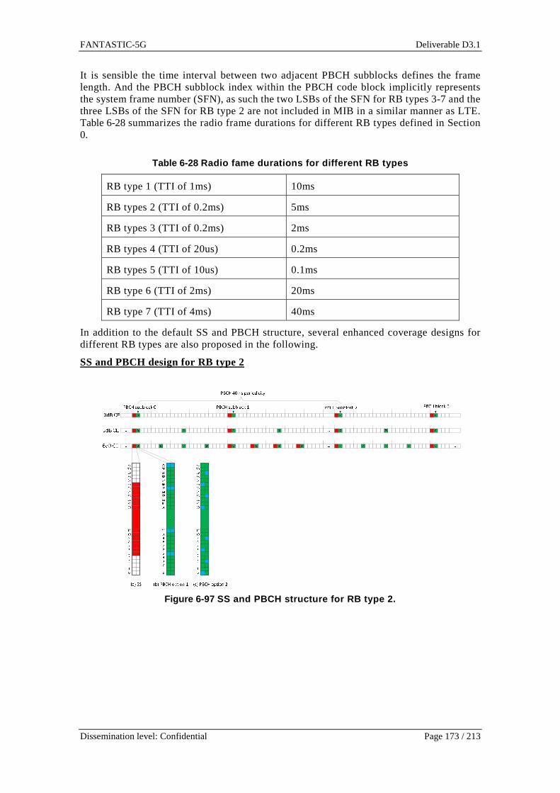
FANTASTIC-5G Deliverable D3.1
Dissemination level: Confidential Page 173 / 213
It is sensible the time interval between two adjacent PBCH subblocks defines the frame length. And the PBCH subblock index within the PBCH code block implicitly represents the system frame number (SFN), as such the two LSBs of the SFN for RB types 3-7 and the three LSBs of the SFN for RB type 2 are not included in MIB in a similar manner as LTE. Table 6-28 summarizes the radio frame durations for different RB types defined in Section 0.
Table 6-28 Radio fame durations for different RB ty pes
RB type 1 (TTI of 1ms) 10ms
RB types 2 (TTI of 0.2ms) 5ms
RB types 3 (TTI of 0.2ms) 2ms
RB types 4 (TTI of 20us) 0.2ms
RB types 5 (TTI of 10us) 0.1ms
RB type 6 (TTI of 2ms) 20ms
RB type 7 (TTI of 4ms) 40ms
In addition to the default SS and PBCH structure, several enhanced coverage designs for different RB types are also proposed in the following.
SS and PBCH design for RB type 2
Figure 6-97 SS and PBCH structure for RB type 2.

FANTASTIC-5G Deliverable D3.1
Dissemination level: Confidential Page 174 / 213
The SS and PBCH structures for RB type 2 are illustrated in Figure 6-97. In addition, the repetition based coverage extension design for SS and PBCH is also shown in the figure. It should be noted that the SS RB does not include DMRS. In each PBCH RB, there are 120 available REs used for the PBCH transmission. As mentioned above, to achieve similar PBCH coding gain, 8 PBCH subblocks of 240bits are evenly distributed in 40ms time window. Moreover, as shown in Figure 6-97, two DMRS pattern examples can be used for the PBCH coherent demodulation. Similar to LTE, transmit diversity scheme can be used to enhance the coverage of PBCH. In case of multiple antenna transmission, the DMRS in Figure 6-97shall be allocated to different antenna ports so that the DMRS of particular antenna port is evenly distributed over time and frequency domain.
SS and PBCH design for RB types 3-7
Figure 6-98 SS and PBCH structure for RB types 3-7.
Figure 6-99 PBCH CE structure for RB types 3-7.

FANTASTIC-5G Deliverable D3.1
Dissemination level: Confidential Page 175 / 213
Figure 6-98 shows the SS and PBCH structures of RB types 3-7. Due to the RB dimension of type 3, 4 and 5 being same as LTE, the placement of SS and PBCH in the RB is similar as LTE. Figure 6-99illustrates two PBCH coverage extension design for RB types 3-7. It is envisioned that the PBCH coverage extension may be required for both mid-high frequency MBB and low cost MMC. Similar to RB type 2, it is shown from Figure 6-98 and Figure 6-99 that two DMRS pattern examples can be used for the PBCH coherent demodulation.
6.6.4.2 Resource partition specific discovery signa l for RRM
To save the system overhead and power consumption, it is envisioned that the “always-on” cell-specific reference signal (CRS) is not required for resource partitions with new RB types.
To enable radio resource measurement for specific resource partition, the partition specific discovery signal or CSI-RS needs to be designed. For RB types 3-7, the LTE like CSI-RS can be adopted. Fig. 8 shows two CSI-RS examples for RB type 2.
Figure 6-100 CSI-RS patterns for RB type 2.
It is shown from Figure 6-100 that 10 CSI-RS antenna ports numbered as x15-x24 and 8 CSI-RS antenna ports numbered as x15-x22 can be supported for the RB type 2 partition with DMRS patter 1 and 2, respectively. The timing configuration of CSI-RS can be designed in a similar manner of LTE. Specifically, different periodicities in terms of TTIs, such as 5, 10, 20, 40 and 80 TTIs can be configured to a UE depending on the UE mobility estimates. The LTE Gold sequence based pseudo-random sequence can be reused, and the sequence shall be initialized with the CSI-RS sequence ID of the configured CSI-RS process at the start of each CSI-RS OFDM symbol. The maximum antenna ports of each CSI-RS process shall be 10 and 8 for CSI-RS option 1 and 2 in Figure 6-100, respectively.

FANTASTIC-5G Deliverable D3.1
Dissemination level: Confidential Page 176 / 213
6.6.4.3 Extended primary partition SIB for secondar y partition signalling
As described in Section 0, when a system supports multiple resource partitions which are based on different RB types, one special resource partition can be defined as the primary partition of the system which serves the majority of the camped UEs in the system, and other resource partitions can be denoted as secondary resource partitions. Typically, the low frequency resource partition which provides normal voice and data service coverage, can serve as the primary partition of the system.
It is plausible that the primary partition SIB can be enhanced to transmit the common information about the non-standalone resource partitions such as the RB type, resource allocation, resource partition specific CSI-RS configuration etc.
For example, as shown in Figure 6-78, some resource partitions can be overlapped in both time and frequency domain. And these overlapped resource partitions can be active at the same time. To ensure the UEs in the primary partition to have unambiguous RE mapping when the allocated primary PRB overlapping with some secondary resource partitions, it is more efficient to broadcast the resource allocation information about the embedded secondary partitions in the SIB of the primary partition. Otherwise, such information may need to be signalled by UE dedicated signalling, which can cause huge signalling overhead.
6.6.4.4 Multiple service-specific resource partitio n aggregation
When a UE is capable of supporting multiple services operating at different RB types, the UE may require these services simultaneously. For example, an application of the UE is receiving MBB service like high definition live video streaming while another background application of the UE is performing a MTC service which may belong to one of MMC/MCC/V2X services. In such situation, the UE needs to communicate with different resource partitions simultaneously. In this section, we propose two methods to enable the UE to concurrently receive multiple services.
Method 1: Extended EPDCCH set aggregation
This method can be applied to aggregate multiple resource partitions with scheduled access. And secondary partitions can be viewed as special data resource regions with different RB types inside the primary partition. This method extends the current feature of EPDCCH in LTE. The basic procedure is illustrated in Figure 6-101.

FANTASTIC-5G Deliverable D3.1
Dissemination level: Confidential Page 177 / 213
Figure 6-101 Signalling diagram for extended EPDCCH set aggregation.
The signalling procedure of extended EPDCCH set aggregations is described as follows. • Phase 1: RRC connection establishment and UE capability indication to the
network o Step 1: UE establishes the RRC connection with the selected 5G eNB via
the primary partition responsible for control plane functions. • The primary partition provides the common search space of control
channels for 5G RAT for SI, RACH response and paging transmission. Moreover, the initial UE specific control channel search space is also allocated in primary partition only.
o Step 2: UE signals its capability of supporting service specific partition to
the network.
• Phase 2: EPDCCH Reconfiguration with multiple service specific EPDCCH sets
o Step 3: Based on the UE capability of supporting multiple service-specific
resource partitions, the eNB reconfigures the UE specific search space with multiple EPDCCH sets by UE dedicated RRC signalling. Each EPDCCH set shall be allocated within the respective resource partition. For each configured EPDCCH set, the reconfiguration may include the following information:
FANTASTIC-5G Deliverable D3.1
Dissemination level: Confidential Page 178 / 213
• RB type of the EPDCCH set and its scheduled partition. • Resource allocation of the partition: time-frequency resource
positions and reoccurrence periodicity. It may be non-overlapped, partially overlapped, fully overlapped with primary partition.
• Resource allocation of EPDCCH set inside the partition. • Partition specific CSI-RS configuration of the partition
o CSI-RS sequence ID o Number of antenna ports o Time-frequency resource allocation for CSI-RS: bandwidth and
TTI in a frame and transmission periodicity in terms of number of RBs and TTIs defined in the secondary partition shall be signalled.
• Phase 3: UE monitors multiple configured EPDCCH sets
o Step 4: UE monitors multiple reconfigured EPDCCH sets allocated in different resource partitions. The EPDCCH schedules downlink or uplink data packet transmitted in the respective resource partition.
Method 2: Extended carrier aggregation
Compared to the above “Method 1”, this method is more generic approach applicable to all kinds of resource partition aggregation. With the presence of self-contained physicals channel and reference signals, some resource partition can support standalone operation. This method reuses the principle of the carrier aggregation in the LTE. The basic procedure is described as follows and illustrated in Figure 6-102.

FANTASTIC-5G Deliverable D3.1
Dissemination level: Confidential Page 179 / 213
Figure 6-102 Signaling diagram for extended CA for partition aggregation.
• Phase 1: RRC connection establishment and UE capability indication to the network
o Step 1: UE establishes the RRC connection with the selected 5G eNB via the primary partition serving as the primary cell of the UE.

FANTASTIC-5G Deliverable D3.1
Dissemination level: Confidential Page 180 / 213
o Step 2: UE signals the supported service specific RB types to the network.
• Phase 2: Secondary resource partitions aggregation.
o Step 3: The primary resource partition requests UE to perform RRM of supported secondary partitions and report the measurement results thereof. The measurement request information about the secondary partition can be as follows
• RB type of the partition • SS and PBCH configuration of the partition:
o SS sequence ID defining the partition ID. o Supported PBCH coverage extension o Resource allocation for SS and PBCH: frequency location and
radio frame boundary shall be signalled, and the SS and PBCH allocation of secondary partition can be derived from its RB Type and radio frame boundary.
• Partition specific CSI-RS configuration o CSI-RS sequence ID o Number of antenna ports o Time-frequency resource allocation for CSI-RS: bandwidth and
TTI in a frame and transmission periodicity in terms of number of RBs and TTIs defined in the secondary partition shall be signalled.
o Step 4: Based on the UE measurement results, the eNB selects and
configures one or several service-specific resource partitions as secondary cells (SCell), identified by the partition ID, to the UE, each SCell configuration may include the following configurations:
• Partition ID. • The following information is optional since they can be received
from the MIB/SIB of the secondary partition. o Resource allocation of the partition: time-frequency resource
positions and reoccurrence periodicity. It may be non-overlapped, partially overlapped, fully overlapped with primary partition.
o Supported link direction: downlink/uplink only, or both downlink and uplink transmission.
o Physical downlink/uplink control channel configuration. � Partition specific common search space configuration
• Resource block allocation • Partition-specific SI-RNTI, RA-RNTI, P-RNTI.
These RNTIs can be hardcoded in the specification. � UE specific search space configuration
• Resource block allocation • C-RNTI.
o Random access resource configuration. � Resource pool allocations � Configurations for 5G physical random access channel.
o Step 5 (optional): If the uplink transmission is supported in the secondary
partition, UE may perform the contention based or contention-free random access procedure to the configured SCell.
• Phase 3: UE monitors multiple configured secondary cells.

FANTASTIC-5G Deliverable D3.1
Dissemination level: Confidential Page 181 / 213
o Step 6: UE starts to monitor the downlink data allocation or uplink data assignment for the configured SCell using secondary resource partitions. Such downlink data allocation or uplink assignment may be signalled by the physical downlink control channel in the primary cell or secondary cell.
6.6.5 RACH for MMC The complete procedure of the extended RA process for MMC is illustrated in Figure 6-103.
Figure 6-103 Extended RA process [KMH+14].
Simulations are performed in this section to test the performance of the extended RA method for MMC. The general settings are listed in Table 6-29.
Table 6-29 Simulation settings
Number of preambles 64 Number of initial users 200 Number of new users in each transmission period 10 Detection probability 0.9 Signal to noise ratio 5dB
An important metric for RACH, as shown in Figure 6-104, is the number of random access attempts in order to obtain uplink resources from the eNB. The proposed method is compared with other two constant multiple UL grants methods, i.e., 1 UL grant for each preamble, 3 UL grants for each preamble, and 4 UL grants for each preamble. It can be observed that one UL grant per preamble results in larger numbers of random access attempts, which is not good for reducing access latencies. On the other hand, 3 or 4 UL grants per preamble reduce the number of random access attempts as there are more UL resources assigned to UEs.
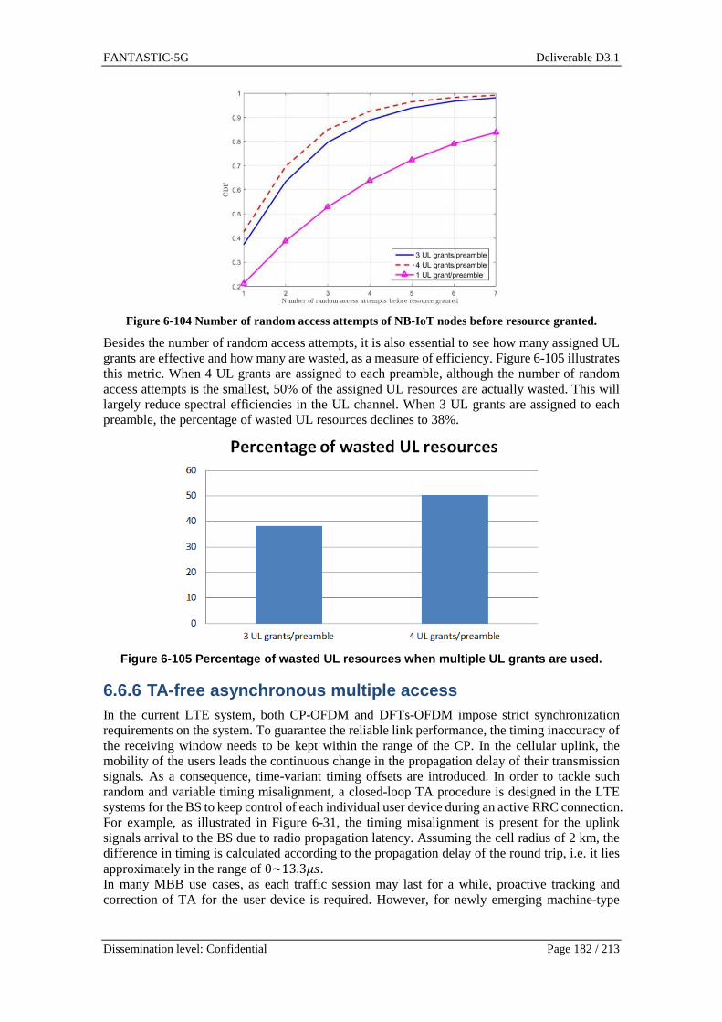
FANTASTIC-5G Deliverable D3.1
Dissemination level: Confidential Page 182 / 213
Figure 6-104 Number of random access attempts of NB-IoT nodes before resource granted.
Besides the number of random access attempts, it is also essential to see how many assigned UL grants are effective and how many are wasted, as a measure of efficiency. Figure 6-105 illustrates this metric. When 4 UL grants are assigned to each preamble, although the number of random access attempts is the smallest, 50% of the assigned UL resources are actually wasted. This will largely reduce spectral efficiencies in the UL channel. When 3 UL grants are assigned to each preamble, the percentage of wasted UL resources declines to 38%.
Figure 6-105 Percentage of wasted UL resources when multiple UL grants are used.
6.6.6 TA-free asynchronous multiple access In the current LTE system, both CP-OFDM and DFTs-OFDM impose strict synchronization requirements on the system. To guarantee the reliable link performance, the timing inaccuracy of the receiving window needs to be kept within the range of the CP. In the cellular uplink, the mobility of the users leads the continuous change in the propagation delay of their transmission signals. As a consequence, time-variant timing offsets are introduced. In order to tackle such random and variable timing misalignment, a closed-loop TA procedure is designed in the LTE systems for the BS to keep control of each individual user device during an active RRC connection. For example, as illustrated in Figure 6-31, the timing misalignment is present for the uplink signals arrival to the BS due to radio propagation latency. Assuming the cell radius of 2 km, the difference in timing is calculated according to the propagation delay of the round trip, i.e. it lies approximately in the range of 0~13.3;h. In many MBB use cases, as each traffic session may last for a while, proactive tracking and correction of TA for the user device is required. However, for newly emerging machine-type
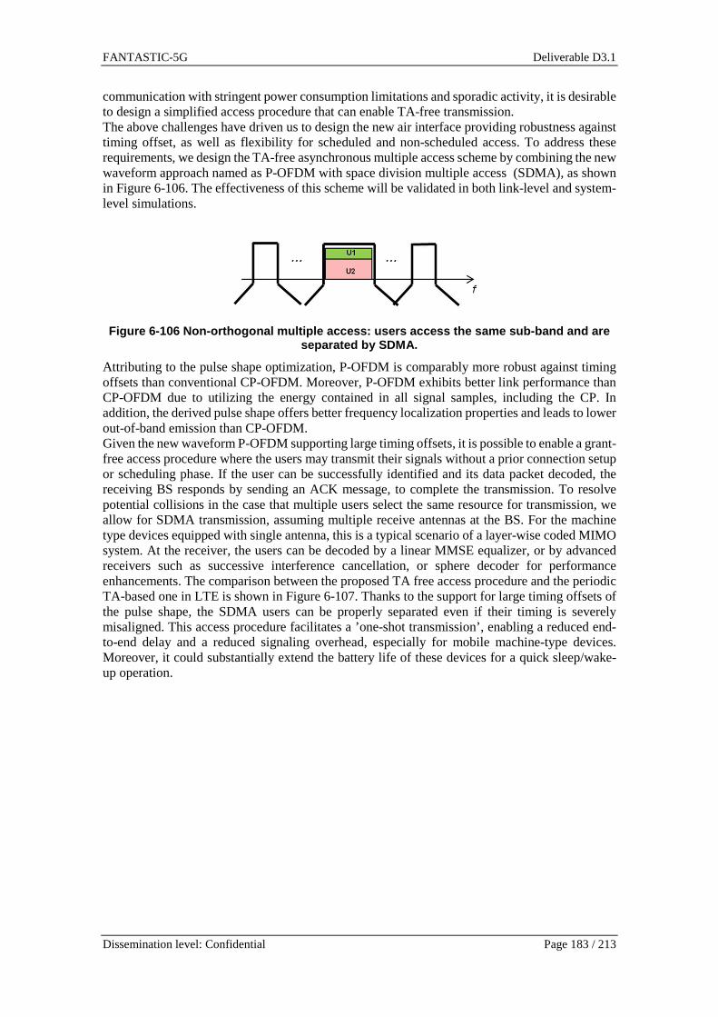
FANTASTIC-5G Deliverable D3.1
Dissemination level: Confidential Page 183 / 213
communication with stringent power consumption limitations and sporadic activity, it is desirable to design a simplified access procedure that can enable TA-free transmission. The above challenges have driven us to design the new air interface providing robustness against timing offset, as well as flexibility for scheduled and non-scheduled access. To address these requirements, we design the TA-free asynchronous multiple access scheme by combining the new waveform approach named as P-OFDM with space division multiple access (SDMA), as shown in Figure 6-106. The effectiveness of this scheme will be validated in both link-level and system-level simulations.
Figure 6-106 Non-orthogonal multiple access: users access the same sub-band and are
separated by SDMA.
Attributing to the pulse shape optimization, P-OFDM is comparably more robust against timing offsets than conventional CP-OFDM. Moreover, P-OFDM exhibits better link performance than CP-OFDM due to utilizing the energy contained in all signal samples, including the CP. In addition, the derived pulse shape offers better frequency localization properties and leads to lower out-of-band emission than CP-OFDM. Given the new waveform P-OFDM supporting large timing offsets, it is possible to enable a grant-free access procedure where the users may transmit their signals without a prior connection setup or scheduling phase. If the user can be successfully identified and its data packet decoded, the receiving BS responds by sending an ACK message, to complete the transmission. To resolve potential collisions in the case that multiple users select the same resource for transmission, we allow for SDMA transmission, assuming multiple receive antennas at the BS. For the machine type devices equipped with single antenna, this is a typical scenario of a layer-wise coded MIMO system. At the receiver, the users can be decoded by a linear MMSE equalizer, or by advanced receivers such as successive interference cancellation, or sphere decoder for performance enhancements. The comparison between the proposed TA free access procedure and the periodic TA-based one in LTE is shown in Figure 6-107. Thanks to the support for large timing offsets of the pulse shape, the SDMA users can be properly separated even if their timing is severely misaligned. This access procedure facilitates a ’one-shot transmission’, enabling a reduced end-to-end delay and a reduced signaling overhead, especially for mobile machine-type devices. Moreover, it could substantially extend the battery life of these devices for a quick sleep/wake-up operation.

FANTASTIC-5G Deliverable D3.1
Dissemination level: Confidential Page 184 / 213
Figure 6-107 TA-free access procedure.
The link performance in Figure 6-108 is evaluated in terms of 1% outage spectral efficiency which is the maximum achievable rate for non-ergodic fading channels. More particularly, we consider the spectral efficiency performance for P-OFDM, CP-OFDM with normal CP length and CP-OFDM with the changing of its CP numerology. The motivation of the last scheme is that, by changing the CP length, CP-OFDM is able to enhance its robustness against timing offsets. However, it is at cost of spectral efficiency as the product of TF will be increased, and the SNR loss is also enlarged due to removing ”CP” in the mismatching window. Note that herein the extended CP-length does not correspond to the extended CP case in LTE, but means the CP is extended to be the sum of normal CP length given by LTE (i.e., largest channel time dispersion assumed) and the maximum timing misalignment introduced by the propagation delay in case of asynchronous transmission.
Figure 6-108 Outage spectral efficiency for pulse-s haped OFDM, OFDM, and OFDM with
extended CP (2 users, BS with 4 RX, ETU channels wi th random timing offset).
On system level, we compare the number of successful connections based on CP-OFDM and P-OFDM with non-orthogonal access under user mobility without TA tracking. Using the assumptions from METIS Test Case 11 description [METI13-D11] and the random walk model, we evaluate the number of connections and transmission success rate for users at different

FANTASTIC-5G Deliverable D3.1
Dissemination level: Confidential Page 185 / 213
velocities. Due to the user mobility, timing misalignment is present when multiple users transmit in a non-orthogonal manner. The numerical results show that for an average user velocity of 12 km/h, P-OFDM achieves ca. 1.4 times the number of successful connections of CP-OFDM. If the user velocity increases to 30 km/h, the gain is more dominant, yielding an improvement of the number of successful connections for P-OFDM over CP-OFDM by a factor of two. Next, from the access latency perspective, we evaluate the latency for transmission of a single packet using ”one-shot transmission” scheme and compared it to the LTE access procedure relying on the connection setup phase. “One-shot transmission” assumes no connection setup process as used in LTE. However, it also includes the retransmissions after collisions. We measure the delay between the first transmission and the successful reception of the ACK signal. Figure 6-109 shows the results for the median and the 90-percentile, the latter covering required retransmissions if the first transmission was not successful. Results show that the new access scheme based on the designed pulse shape can effectively reduce the overall delay compared LTE by 18 ms in both cases.
Figure 6-109 Access latency performance: LTE CP-OFD M vs. pulse shaped OFDM.
The above initial investigations assume only a small number of simultaneously active users separated by SDMA on each resource, which could be ensured by a semi-persistent scheduling of users to sub-bands. A larger number of users can be supported with simple linear equalization by scaling up the number of receive antennas at the BS as in massive MIMO. Alternatively, the proposed P-OFDM may also be combined with non-orthogonal multiple access schemes that allow for more active users than receive antennas, which requires in general advanced iterative receivers to detect the individual transmit signals. In this case, it is essential that the channel codes are jointed designed with the multiuser detector. The complexity of the detector may be significantly reduced by a sparse resource mapping per user such that only few users interfere on each resource. This has the additional benefit that the channels only have to be estimated on the resources occupied by a user so that the overhead for channel estimation is reduced. The design of optimized channel codes for non-orthogonal multiple access will be investigated in WP4, where sparse resource mappings are explicitly taken into account as a degree of freedom.
6.7 Physical layer design for core services
6.7.1 Mobile Broadband
6.7.1.1 Requirements and Challenges
Table 6-30, Table 6-31, and Table 6-32 provide a summary on service specific KPIs aggregated over three different use cases, namely, 50 Mbps everywhere, high speed train and dense urban society below 6GHz.
Table 6-30 50 Mbps everywhere
50 Mbps everywhere

FANTASTIC-5G Deliverable D3.1
Dissemination level: Confidential Page 186 / 213
KPI no.
KPI definition
Req. Lev.
Requirement definition
UoM Notes
User Exp.
KPI 0
User experienced
data rate
50 Mbps (DL), 25 Mbps (UL)
Mbps See D2.1
Syst. Perf.
KPI 1
Traffic Density
Suburban : DL : 20
Gbps/km2
Suburban : UL : 10
Gbps/km2
Rural : DL :
5 Gbps/km2
Rural : UL : 2.5 Gbps/km2
Gbps/km2
See D2.1
User Exp.
KPI 2
Latency
10 ms ms See D2.1
Syst. Perf.
KPI 3
Coverage
99.999% of the area where the service is
provided
% See D2.1
User Exp.
KPI 4
Mobility 0 - 120 km/h km/h See D2.1
Syst. Perf.
KPI 5
Connection density
Suburban: 400 users/km2
Rural: 100 users/km2
Users/km2 See D2.1
User Exp.
KPI 6
Reliability/availability
Reliability: 95%
Availability: 99%
% See D2.1
Syst. Perf.
KPI 7
Complexity reduction
50% % See D2.1
Syst. Perf.
KPI 8
Energy efficiency
50% % See D2.1
Req. Lev.
Primary Secondary
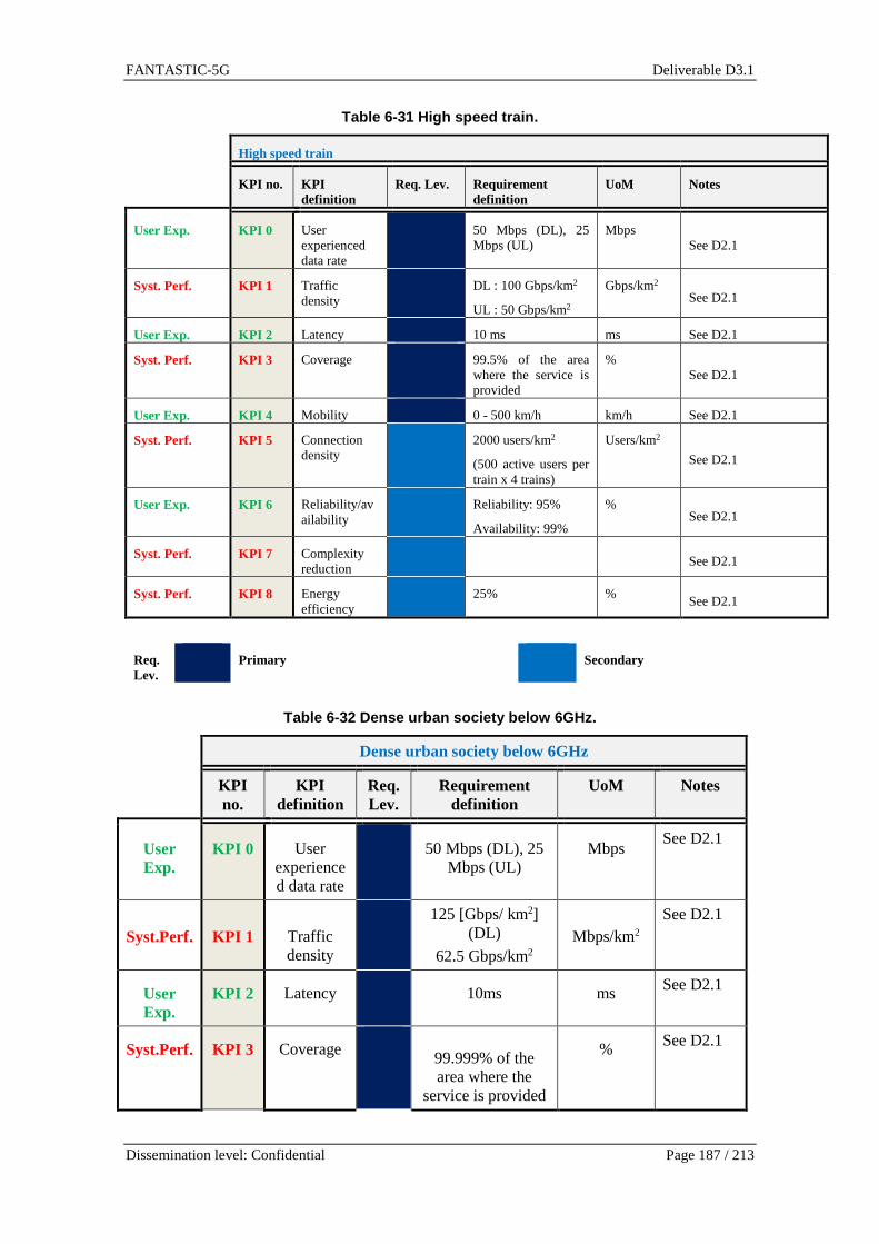
FANTASTIC-5G Deliverable D3.1
Dissemination level: Confidential Page 187 / 213
Table 6-31 High speed train.
High speed train
KPI no. KPI definition
Req. Lev. Requirement definition
UoM Notes
User Exp. KPI 0 User experienced data rate
50 Mbps (DL), 25 Mbps (UL)
Mbps See D2.1
Syst. Perf. KPI 1 Traffic density
DL : 100 Gbps/km2
UL : 50 Gbps/km2
Gbps/km2 See D2.1
User Exp. KPI 2 Latency 10 ms ms See D2.1
Syst. Perf. KPI 3 Coverage 99.5% of the area where the service is provided
% See D2.1
User Exp. KPI 4 Mobility 0 - 500 km/h km/h See D2.1
Syst. Perf. KPI 5 Connection density
2000 users/km2
(500 active users per train x 4 trains)
Users/km2
See D2.1
User Exp. KPI 6 Reliability/availability
Reliability: 95%
Availability: 99%
% See D2.1
Syst. Perf. KPI 7 Complexity reduction
See D2.1
Syst. Perf. KPI 8 Energy efficiency
25% % See D2.1
Req. Lev.
Primary Secondary
Table 6-32 Dense urban society below 6GHz.
Dense urban society below 6GHz
KPI no.
KPI definition
Req. Lev.
Requirement definition
UoM Notes
User Exp.
KPI 0 User experienced data rate
50 Mbps (DL), 25
Mbps (UL) Mbps
See D2.1
Syst.Perf. KPI 1 Traffic density
125 [Gbps/ km2] (DL)
62.5 Gbps/km2 Mbps/km2
See D2.1
User Exp.
KPI 2 Latency 10ms ms See D2.1
Syst.Perf. KPI 3 Coverage 99.999% of the area where the
service is provided
% See D2.1

FANTASTIC-5G Deliverable D3.1
Dissemination level: Confidential Page 188 / 213
User Exp.
KPI 4 Mobility On demand, 0-100
km/h
km/h See D2.1
Syst.Perf. KPI 5 Connection density
200-2500/km2 users/km2
See D2.1
User Exp.
KPI 6 Reliability/availability
95% % See D2.1
Syst.Perf. KPI 7 Complexity reduction
Comparable to
today - See D2.1
Syst.Perf. KPI 8 Energy efficiency
The network energy
consumption should be
comparable to the energy
consumption of today’s
metropolitan deployments, despite the drastically
increased amount of traffic.
% See D2.1
Req. Lev.
Primary Secondary
Based on these requirements, key technology components for MBB service specific radio interface can be identified and generic guideline for radio interface design can be provided. It is worth noting that the list of identified components is not targeting to be comprehensive to cover all L1 and L2 related aspects. Instead of this, the design guideline aims at highlighting key technical components that address KPIs provided in xx
• To support low user plane latencies (KPI2), efficient frame structure needs to enable: o Short TTI cascaded with user specific DL and UL control signals o Support for low complexity and high energy efficiency transceiver side
processing • To enable enhanced spectral efficiencies, data rates (KPI0) and coverage (KPI3) for both
DL and UL, radio interface needs to provide flexible support for different duplexing and spectrum configurations:
o Both FDD and TDD applicable for macro and small cell scenarios o Dynamic TDD enables support for traffic adaptability o each TTI can be dynamically selected to carry UL or DL data upon needed o Robustness against cross-link interference, e.g. dynamic TDD o Efficient spectrum aggregation including also aggregation between FDD and
TDD bands

FANTASTIC-5G Deliverable D3.1
Dissemination level: Confidential Page 189 / 213
• To facilitate high traffic volume increase (KPI1), connection density (KPI6) and enhanced coverage (KPI3) at user and control plane, radio interface shall provide native support for massive MIMO operations:
o Support for efficient multiuser (MU)-MIMO operation o Advanced multi-user precoding and detection techniques o Support for scalability in terms of different number of antenna ports
• To provide support for lean common control plane design with enhanced energy efficiency (KPI8) and minimized signaling overheads (KPI7), radio interface needs to enable control channels with reduced signaling overheads:
o Support for common control; minimum information needed to access to a cell: e.g. time/ frequency synchronization, cell discovery, access to system information
o Support for dedicated control: user specific control w/ user-specific reference symbols avoiding common reference symbols
o Commonalities between user and control plane processing aspects • To support high data rates (KPI0) and low latencies (KPI2) at user plane, radio interface
needs to enable channel coding and re-transmission schemes: o Support for low complexity and latency at both encoding and decoding parts o Coupled with inbuilt capability of efficient frame structure to enable minimized
round-trip-time (RTT) for HARQ re-transmissions • To enable high spectral efficiencies (KPI0) and support for mobility (KPI4), radio
interface shall provide support for waveform(s) that have the following properties: o Low complexity, latency and high energy efficiency for transceiver side
processing o Demonstrate feasible trade-offs between performance and processing complexity
• To facilitate enhanced spectral efficiencies (KPI0), traffic densities (KPI1),latencies (KPI2), coverage (KPI3), and mobility (KPI4) operation, radio interface needs to provide support for advanced RRM and multi-connectivity mechanisms
o Flexible resource allocation o Efficient traffic and mobility management o Multi-connectivity methodologies operating
� on same carrier targeting for interference management , e.g. different COMP and ICIC schemes
� on different carrier targeting load balancing, mobility support , e.g.dual connectivity and (DC) and carrier aggregation (CA)
6.7.1.2 Baseline design
Since the advent of LTE in 3GPP workshop in 2004, LTE has significantly evolved and will continue to further develop in upcoming releases. 3GPP Release 8 defined the first LTE specification enabling 150 Mbps downlink peak rate with 20 MHz bandwidth. With respect to Release 8, Release 9 included a few additional new features. Both 3GPP releases 8 and 9 enabled LTE to become a successful technology for delivering mobile broadband data and Voice over LTE (VoLTE)[Nok15]. In 3GPP Release 10, the second phase of LTE was introduced, referred as LTE-Advanced. Release 10 was finalized 2011 and the first networks with LTE-Advanced features became available 2013.In comparison to the first phase of LTE, the peak data rates were significantly enhanced in Release 10 by carrier aggregation technology, e.g. with 2x20MHz up to 300 Mbps in downlink. The maximum peak rate of Release 10 with 5x20 MHz configuration can provide up to 1 Gbps with 2x2 MIMO and 64-QAM, and even 3.9 Gbps with 8x8 MIMO [NOK-white-paper-2015]. Both 3GPP Release 11 and Release 12 have further enhanced LTE-Advanced specification. Release 11 and Release 12, were finalized in 3GPP in December 2012 and in March 2015, respectively. The third phase of LTE technology is defined in Releases 13 and 14 under the name of LTE-Advanced Pro that was agreed in 3GPP in October 2015 [LAP15]. It is assumed that Release 13 will be finalized in June 2016 and the work will continue with Release 14 [Nok15]. Table 6-33provides a list of supported different UE categories and corresponding data rates

FANTASTIC-5G Deliverable D3.1
Dissemination level: Confidential Page 190 / 213
defined in Rel-13 LTE-A-PRO specification [36.306]. It is worth noting that all the combinations of DL and UL mentioned the table are not necessarily supported in Rel-13 specification. Therefore, further details of supported DL and UL combinations in Rel-13 can be found in [36.306].Recently, two new DL and UL UE category classes have been introduced in 3GPP WG1#83 meeting [R1-157751] that enable to provide support up to 32 component carriers resulting in 25 Gbps data rate with 8 layer MIMO (CAT 17) and 256-QAM in DL and 9.6 Gbps with 2 layer MIMO and 64-QAM (CAT 14).
Table 6-33 LTE-A-Pro (Rel-13) supported UE DL and U L categories [36.306].
DL/UL UE Category
Maximum DL [Mbps] Maximum UL [Mbps]
Category 0 1 1
Category 1 10 5
Category 2 50 25
Category 3 100 50
Category 4 150 50
Category 5 300 75
Category 6 300 50
Category 7 300 100
Category 8 3000 1500
Category 9 450 50
Category 10 450 100
Category 11 600 50
Category 12 600 100
Category 13 390 150
Category 14 3900 9600
Category 15 800 -
Category 16 1051 -
Category 17 25000 -
6.7.1.3 Summary of technology components
In the following, relevant 3GPP LTE-A Rel-12 and Rel-13 based technology components from the perspective of MBB service for WP3 are summarized:
3GPP Release 12 based technology components
• Dual connectivity [36.842] o Multi-connectivity enables support for different user- and control plane
operations within same radio access technology with different carrier frequencies without need for low latency backhaul
o Enables efficient load balancing and load offloading mechanisms • Enhanced Cooperative Multi-Point (eCOMP) [36.874]:
o COMP with non-ideal backhaul • Aggregation of FDD and TDD [36.847]

FANTASTIC-5G Deliverable D3.1
Dissemination level: Confidential Page 191 / 213
o Enables efficient use of both FDD and TDD bands • Enhanced Interference Mitigation and Traffic Adaptation (eIMTA) [36.828]:
o Introduced in Release 11 and actual work item conducted under Release 12
o Facilitates the use of dynamic TDD where the ratio of both DL and UL subframes can be flexibly adapted cell specifically according to traffic fluctuations
• Small cell enhancements: Physical layer aspects [36.872] o Support for 256-QAM in DL o Discovery signal support for secondary cells and cell DTX
3GPP Release 13 based technology components
• Carrier aggregation over 32 component carriers (CC) for both DL and UL [R1-157751] o Enables 25 Gbps DL peak rate with 8 layer MIMO and 256QAM (CAT 17 UE) o 9.6 Gbps UL with 2 layer MIMO and 64QAM (CAT 14 UE)
• Licensed Assisted Access (LAA) [36.889] o Combines the use of licensed and unlicensed spectrum with carrier aggregation
technology. • Full-dimensional (FD)-MIMO [36.897]
o Provides a support for uniform linear antenna arrays (ULA) and rectangular antenna arrays (URA)
o Enhances spectral efficiency by increasing the number of antenna ports from 8 up to 16. It is worth noting that a mapping between antenna port and physical antenna element is not necessarily one-to-one.
o Enables the leverage of large antenna arrays at eNB o Provides support for new 2D, i.e. Azimuth and elevation, codebooks with non-
beamformed CSI-RS based transmission schemes o Enables support for beamformed transmission by using cell or user specific
beamformed CSI-RSs. • Multi-User Superposition Transmission (MUST) [36.859]
o Evolution of network assisted interference cancellation introduced in Release 12 that provided support for advanced receivers with network assistance, e.g. non-linear ML based receivers
o Enhances spectral efficiency of a serving cell by advanced multi-user interference mitigation and multiplexing scheme.
6.7.2 Massive machine communication
6.7.2.1 Requirements and challenges
Table 6-34 Primary KPI targets for MMC according to D2.1.
Use case 3: Sensor networks
KPI no.
KPI definition
Req. Lev.
Requirement definition
UoM Notes
Syst.Perf. KPI 3
Coverage
20 dB more than legacy systems
coverage (both UL and DL) with 100%
coverage as a baseline
dB See D2.1
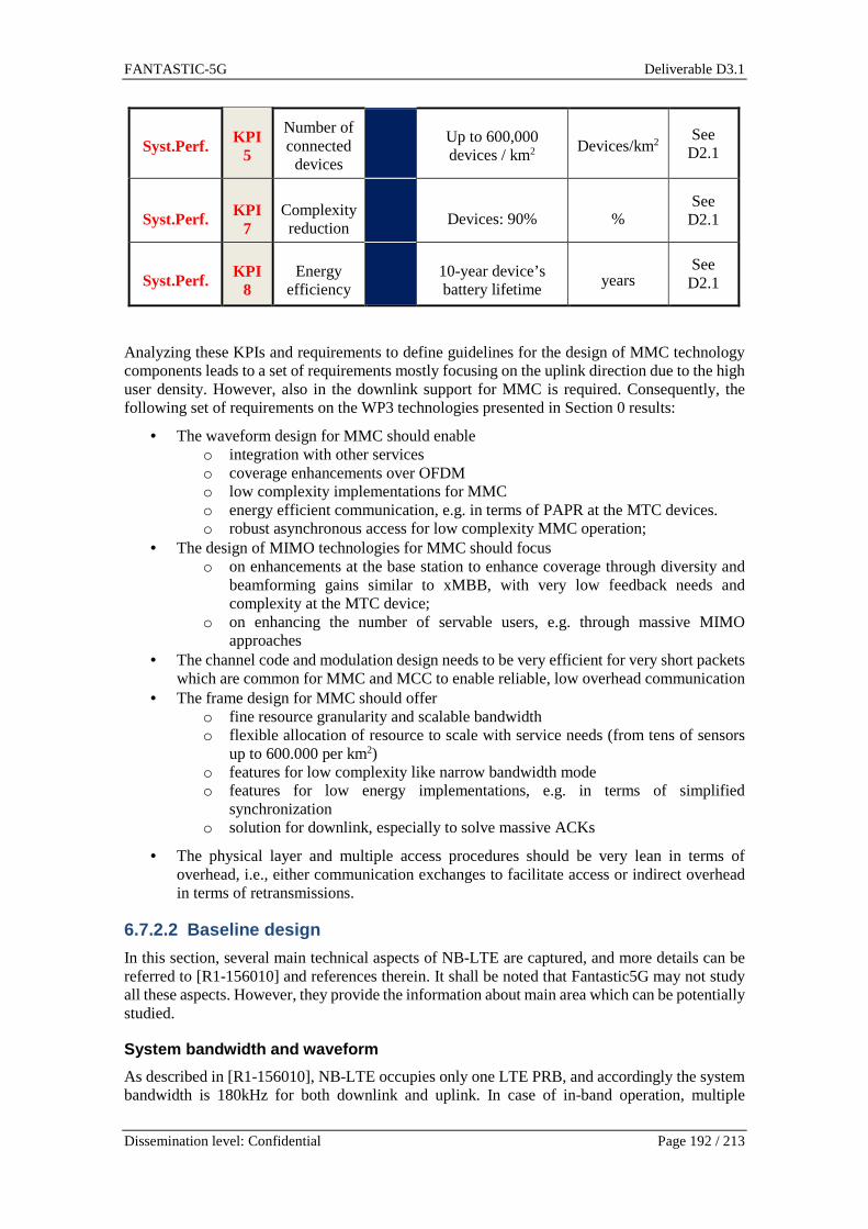
FANTASTIC-5G Deliverable D3.1
Dissemination level: Confidential Page 192 / 213
Syst.Perf. KPI 5
Number of connected devices
Up to 600,000 devices / km2
Devices/km2 See D2.1
Syst.Perf. KPI 7
Complexity reduction
Devices: 90% % See D2.1
Syst.Perf. KPI 8
Energy efficiency
10-year device’s battery lifetime
years See D2.1
Analyzing these KPIs and requirements to define guidelines for the design of MMC technology components leads to a set of requirements mostly focusing on the uplink direction due to the high user density. However, also in the downlink support for MMC is required. Consequently, the following set of requirements on the WP3 technologies presented in Section 0 results:
• The waveform design for MMC should enable o integration with other services o coverage enhancements over OFDM o low complexity implementations for MMC o energy efficient communication, e.g. in terms of PAPR at the MTC devices. o robust asynchronous access for low complexity MMC operation;
• The design of MIMO technologies for MMC should focus o on enhancements at the base station to enhance coverage through diversity and
beamforming gains similar to xMBB, with very low feedback needs and complexity at the MTC device;
o on enhancing the number of servable users, e.g. through massive MIMO approaches
• The channel code and modulation design needs to be very efficient for very short packets which are common for MMC and MCC to enable reliable, low overhead communication
• The frame design for MMC should offer o fine resource granularity and scalable bandwidth o flexible allocation of resource to scale with service needs (from tens of sensors
up to 600.000 per km2) o features for low complexity like narrow bandwidth mode o features for low energy implementations, e.g. in terms of simplified
synchronization o solution for downlink, especially to solve massive ACKs
• The physical layer and multiple access procedures should be very lean in terms of overhead, i.e., either communication exchanges to facilitate access or indirect overhead in terms of retransmissions.
6.7.2.2 Baseline design
In this section, several main technical aspects of NB-LTE are captured, and more details can be referred to [R1-156010] and references therein. It shall be noted that Fantastic5G may not study all these aspects. However, they provide the information about main area which can be potentially studied.
System bandwidth and waveform
As described in [R1-156010], NB-LTE occupies only one LTE PRB, and accordingly the system bandwidth is 180kHz for both downlink and uplink. In case of in-band operation, multiple
FANTASTIC-5G Deliverable D3.1
Dissemination level: Confidential Page 193 / 213
narrowband of 180kHz can be allocated by the network according to the traffic needs of the NB-IOT devices in the coverage.
According to the 3GPP agreements in RAN1#83, the LTE CP-OFDM with 15kHz subcarrier spacing is adopted for downlink transmission for all three scenarios. Both single-tone transmission and multi-tone transmission are supported for uplink. The SC-FDMA with 15kHz subcarrier spacing is agreed for the multi-tone transmission. In case of single tone transmission, two possible numerologies with 3.75kHz and 15kHz subcarrier spacing should be configurable, and a cyclic prefix is used as part of the waveform. Specifically, the overhead of CP can be the same as the current LTE.
Frame structure
In the downlink, the current LTE 1ms subframe is reused as the minimum scheduling unit in time. To support very small packet transmission, UE may be scheduled with less than 12 subcarriers in a TTI.
For the uplink with 15kHz subcarrier spacing and multi-tone transmission, the current LTE uplink frame structure can be reused. With 3.75kHz subcarrier spacing and single tone transmission, all the uplink time units in NB-LTE span 4 times those of the corresponding LTE time units. Specifically, a radio subframe and frame in uplink NB-LTE are 4ms and 40ms, respectively. Figure 6-110 illustrates the uplink NB-LTE numerology. The NB-LTE carrier of 180kHz bandwidth comprises 12 subcarriers of 15kHz subcarrier spacing or 48 subcarriers of 3.75kHz subcarrier spacing for multi-tone transmission and single tone transmission, respectively.
Figure 6-110 NB-LTE uplink numerologies for multi-t one and single-tone transmission.
Downlink physical channels and signals
NB-LTE will support the following downlink physical channels and signals.
• NB-PBCH: used for broadcasting essential system information. • NB-PDSCH: used for sending downlink UE data and control information. • NB-EPDCCH: used for carrying downlink control information. • NB-PSS and NB-SSS: used for downlink synchronization and cell search. • NB-CRS: cell-specific reference signal used for channel estimation. • NB-DMRS: optional UE-specific reference signal used for channel estimation.
NB-PSS and NB-SSS
NB-LTE supports two types of synchronization channel density. The periodicity of NB-PSS and NB-SSS can be 20ms and 10ms in lower density and high density option, respectively. In both options, NB-PSS and NB-SSS are transmitted in subframe 4 and 9, respectively. NB-PSS uses the last 11 OFDM symbols in the NB-PSS subframe, and those NB-PSS REs colliding with LTE CRS in case of in-band deployment are punctured to preserve LTE CRS transmission. NB-SSS are transmitted in OFDM symbols 5, 6, 9, 10, 12 and 13 in NB-SSS subframe, and these symbols

FANTASTIC-5G Deliverable D3.1
Dissemination level: Confidential Page 194 / 213
are not colliding with CRS transmission. Unlike in LTE, only one NB-PSS sequence will be used, and 504 NB-SSS sequences will be defined to support the same number of cell IDs as in LTE. NB-PSS is used to determine the subframe timing as well as the frequency offset correction. In addition to cell ID detection, NB-SSS is also used to determine the timing within an 80ms NB-SSS repetition interval.
NB-PBCH
The master system information, i.e., system frame number, for initial cell access is carried on NB-PBCH. In NB-LTE, the NB-PBCH transmission time interval is 640ms, and each NB-PBCH occurrence is transmitted in OFDM symbols 3, 5, 6, 9 and 10 of subframe 0 in each LTE frame. It is clear that the RE mapping of NB-PBCH should avoid collision with the essential LTE signals including PDCCH, CRS and possible MBSFN. Each NB-PBCH time interval is divided into 8 NB-PBCH blocks, each of which contains 8 NB-PBCH occurrences and is masked with a unique scrambling code. As such, the 6 least significant bits of the SFN need not be included in the master information block. To enable channel estimation and coherent demodulation of NB-PBCH, as shown in Figure 6-111, additional NB-LTE CRSs can be defined within the NB-PBCH PRBs.
Figure 6-111 NB-PBCH resource mapping (from R1-1560 10).
NB-PDCCH
NB-PDCCH is used to signal downlink control information. The same design principle of EPDCCH as in Release-13 eMTC is reused. Each NB-PDCCH consists of one or several enhanced control channel elements (ECCEs) according to the aggregation level. Each ECCE consists of four or eight enhanced resource element groups (EREGs). In standalone deployment, all OFDM symbols of each subframe can be utilized for NB-PDCCH resource mapping.
NB-PDSCH
NB-PDSCH is used for UE DL data traffic transmission. The resource elements that are not used for LTE and NB-LTE control channels can be allocated to NB-PDSCH. To reduce the UE decoding complexity and memory consumption, NB-LTE uses the LTE tail-biting convolutional code with LTE rate-matching scheme and QPSK for NB-PDSCH.
Uplink physical channels and signals
NB-LTE supports the following uplink channels.
M-PBCH subframe M-PSS subframe M-SSS subframe
Block 0 Block 1 Block 7
640 ms
80 ms
1 ms
Normal CP
LTE PDCCH
NB LTE PBCH
LTE CRS
NB-LTE CRS Port 0 (if defined)
NB-LTE CRS Port 1 (if defined)

FANTASTIC-5G Deliverable D3.1
Dissemination level: Confidential Page 195 / 213
• NB-PRACH: used by UE to send random access preamble. • NB-PUCCH: used for carrying uplink control information, may not be necessary since
its function can be realized by NB-PRACH and NB-PUSCH. • NB-PUSCH: used for UL data transmission.
NB-PRACH
Three different NB-PRACH formats are defined for different coverage targets, namely normal coverage, robust coverage and extreme coverage. NB-PRACH preamble formats 0 and 1 are based on length-251 Zadoff-Chu sequences with 312.5Hz subcarrier spacing, resulting in 80kHz NB-PRACH bandwidth. The basic random access preamble segment of NB-PRACH preamble formats 0 and 1 is 4ms, consisting of basic symbol duration of 3.2ms and 0.4ms CP and 0.4ms guard time. The NB-PRACH preamble format 0 supports UE with maximum coupling loss (MCL) lower than 144 dB. The NB-PRACH preamble format 1 repeats the basic random access preamble segment by 12 times to support the MCL up to 154dB. The NB-PRACH preamble format 2 is 160ms, and contains two alternating subcarriers. The preambles of format 2 has constant envelope, and thus achieves the maximum PA efficiency. NB-PRACH format 2 supports UE with MCL higher than 154 dB and up to 164dB, therefore can be used in extremely coverage limited locations. The preamble consists of 100 symbols in time and occupies one 2.5 kHz subcarrier in frequency. One preamble (160 ms) achieves NB-PRACH detection probability of 99.26%.
NB-PUSCH
NB-PDCCH can be used for scheduling UL data packet. The DCI formats for scheduling the LTE NB-PUSCH can be reused to assign NB-PUSCH on a NB-LTE carrier. To allocate single tone NB-PUSCH transmission, the NB-PDCCH needs to support additional scheduling granularity. In detail, in cases of UEs in extremely poor coverage and in order to improve multiplexing gains, the smallest scheduling unit of the NB-PUSCH (6 ms in time and 1 subcarrier in frequency) should be supported. It is envisioned that NB-PUSCH bundling and NB-PDCCH repetition will be needed to support reasonable UL transport block size and robust control channel transmission, respectively. NB-PUSCH uses LTE turbo code with LTE rate matching scheme and QPSK. To maintain low PAPR, pi/2-BPSK is also considered for NB-PUSCH modulation.
6.8 Mission critical communication
6.8.1 Requirements and challenges The optimization of latency and reliability/availability sets conflicting requirements for the design of control information. On one hand, the optimization of latency requires removal of the protocol overhead and minimizing the exchange of the signaling messages so that it can fit within the latency budget of a given service. On the other hand, ultra-high levels of reliability and availability (>99.999% in time and space of a given region), implies that the control information should be robustly encoded, with sufficient amount of redundancy in order to be available even during the impairment conditions that are statistically rare. Clearly, besides the control information, ultra-high reliability implies also reliable reception of the data. This can be ensured by increasing the levels of diversity using different means, such as frequency diversity or space diversity. Connections with very low latency cannot rely on time diversity, either simple repetition or another more sophisticated coding in time domain. Another important source of diversity will be the ultra-densification foreseen in 5G deployments, such that one device can simultaneously use more than one radio access point.
As shown in the next section, the current work in 3GPP is chiefly focused on latency reduction, without making specific provisions or recommendations for ultra-reliability, as required for some of the envisioned MCC services. On the other hand, latency can be considered in different context, depending on the specific MCC service in question. For example, uplink reporting of critical sensor information (alarm) considers one-way latency, i.e. until the infrastructure has successfully

FANTASTIC-5G Deliverable D3.1
Dissemination level: Confidential Page 196 / 213
decoded the packet. Interactive services based on Tactile Internet will put constraint on round-trip (two-way) latency. Further on, if an UE starts from a state that is not authenticated, the relevant latency measure may include two-way exchange of multiple messages.
With regards to the PHY-layer techniques, MCC puts forward the following requirements:
• Waveform design o Short TTI that enables low-latency one-way transmission and in combination
with a suitable duplexing strategy, it allows low-latency two-way transmission. o Integration with other services. One specific issue in this sense is the use of
successive interference cancellation, applied at the Base Stations or high-end devices. Note that, when the high-reliability transmission uses many level of diversity, then the equivalent data rate used across all the communication resources is low. This means that an ultra-reliable transmission is sent with a low spectral efficiency in order to have a margin that will provide the necessary reliability. However, if conditions allow, this signal can be decoded and cancelled, thus enabling the receiver to decode other signals that are using higher data rates.
• Use of multiple antennas and MIMO o Use the antennas as sources of space diversity in order to offer high levels of
reliability o Minimize the latency of the training/CSI acquisition process for systems with
massive number of antennas at the side of the infrastructure. • Coding and ARQ protocols
o Use of efficient codes for short amount of data o Explicitly account for the encoding of the control information, rather than using
a simple repetition heuristics for control information and then sophisticated codes for the data part.
o Design of latency-constrained ARQ protocols with adaptive retransmission and suitable power allocation strategies. Note that when there is a deadline on the transmission, water-filling strategies are not optimal, but rather the sender has to increase the transmit power as the transmission deadline approaches.
• Frame design o Robust encoding of the control information o Flexible duplexing and in some cases full duplex transmission in order to enable
low-latency two-way transmissions o Capability to allocate high levels of frequency diversity within a given short time
interval (e.g. a single TTI) in order to enable ultra-high reliability levels.
Table 6-35 KPI and requirement analysis for MCC.
Tactile Internet
KPI no.
KPI definition
Req. Lev.
Requirement definition
UoM Notes
User Exp.
KPI 0 User experienced data rate
50 Mbps (DL), 25
Mbps (UL) Mbps
See D2.1
Syst.Perf. KPI 1 Traffic density
Potentially high Mbps/km2
See D2.1
User Exp.
KPI 2 Latency ≤ 1 ms ms See D2.1

FANTASTIC-5G Deliverable D3.1
Dissemination level: Confidential Page 197 / 213
Syst.Perf. KPI 3 Coverage 99.999% of the area where the
service is provided
% See D2.1
User Exp.
KPI 4 Mobility 0 - 120 km/h
km/h See D2.1
Syst.Perf. KPI 5 Connection density
Not critical users/km2
See D2.1
User Exp.
KPI 6 Reliability/availability
99.999% % See D2.1
Syst.Perf. KPI 7 Complexity reduction
Not critical - See D2.1
Syst.Perf. KPI 8 Energy efficiency
Not critical
% See D2.1
Req. Lev.
Primary Secondary
6.8.2 Baseline design Due to the important impact of packet data latency on the overall system performance and to ensure LTE evolution and competitiveness, a new study item “Study on latency reduction techniques for LTE” (LATRED) has been proposed in [RP-150465] for LTE release 13 with the following objectives:
• Significantly reduce the packet data latency over the LTE air interface for an active UE • Significantly reduce the packet data transport round trip latency for UEs that have been
inactive for a longer period (in connected state).
In addition to improve the responsiveness of the system, packet latency reduction can further increase the average throughput. Specifically, during TCP slow start, the performance is latency limited and improved latency, i.e., shorter packet RTT, can directly improve the average throughput by quickly increasing the TCP congestion window to a certain threshold. Moreover, the reduced latency is also helpful to reduce the L2 buffering requirements in UE and eNB for really high bit rate services.
A number of existing applications including gaming and real time applications like video telephony/conference etc, are envisioned to be positively impacted by improved latency. In addition, a number of new applications such as remote control/driving of vehicles and augmented reality applications including machine type critical communications are supposed to be delay critical and shall be beneficial from the reduced latency techniques.
Due to the objective synergy of MCC core service and the study item LATRED, all the proposed techniques in 3GPP for the SI LATRED can be considered as the baseline designs for MCC core service. This section gives a summary of proposed techniques in both protocol/signaling enhancements and TTI shortening in physical layer. Considering the status of the 3GPP work, the baseline consists chiefly of recommendations for decrease of the latency, while the specification of the mechanisms for ultra-high reliability is subject of a future work.

FANTASTIC-5G Deliverable D3.1
Dissemination level: Confidential Page 198 / 213
6.8.2.1 Protocol enhancements for fast uplink acces s solutions
As described in [RP-150465], fast uplink access solutions will be studied by 3GPP RAN2: • for active UEs and UEs that have been inactive a longer time, but are kept in RRC
Connected, focus should be on reducing user plane latency for the scheduled UL transmission and getting a more resource efficient solution with protocol and signalling enhancements, compared to the pre-scheduling solutions allowed by the standard today, both with and without preserving the current TTI length and processing times;
In several past 3GPP RAN2 meetings, a number of solutions for this SI have been proposed by several companies, and these solutions are documents in [TR36.881]. This section briefly presents several key techniques in [TR36.881]. More details are referred to [TR36.881] and references therein.
Enhanced Semi-Persistent Scheduling
In current Semi-Persistent Scheduling (SPS), the SPS periodicity is configured by the eNB via dedicated RRC signalling, and the minimum SPS periodicity is 10ms. The enhanced SPS shall support a SPS periodicity of 1TTI to allow UL transmission in consecutive subframes. With shorter SPS periodicity, the initial UL transmission may be reduced.
Enhanced UL Grant reception
In current LTE, the UE sends a MAC PDU containing a MAC control element (CE) for padding buffer status report (BSR) and padding bits in response to a dynamic or configured UL grant even if no data is available in the UE MAC buffer and no other MAC CE is needed to be sent. The enhanced UL grant reception shall allow UEs to skip UL grant if no data is available for transmission. This is beneficial to decrease UL interference and improve UE battery efficiency. And UE will continue to send data and/or MAC CEs if any. The eNB may enable such skipping UL grants by RRC dedicated signalling. In case of SPS activation configuration, UE can send an acknowledgement by transmitting zero MAC SDU to confirm the successful reception of the configuration if the UE buffer is empty. After the acknowledgement to activation, UE shall skip those SPS grants when the UE buffer is empty. Similar acknowledgment in the response to the deactivation configuration may be beneficial as well.
Handover latency reduction
The current LTE handover procedure need about 49.5ms, during which a RACH procedure is performed by the UE to establish uplink synchronization to the target cell, and it can take about 13.5ms. Handover latency reduction shall improve the user experience of several applications during handover operation. Two solutions are identified. The solution 1 named as “RACH-less handover” enables UE to accomplish HO without performing RACH procedure to the target cell when the source cell, the target cell and the UE are synchronized in terms of subframe boundary. Eliminating about 13ms of RACH delay during a HO can significantly reduce the data interruption during HO procedure. The second solution is to maintain source eNB connection until the handover to the target eNB is completed. This will enable the continuous transmission of user data from source cell well after the handover procedure. This requires that the UE monitors both source and target links simultaneously, which is similar to the dual connectivity supported in Rel-12.
Contention based PUSCH transmission
In the current LTE pre-scheduling scheme, the eNB will assign one separate UL grant for each UE. However, the preschedule resources shall be wasted if the UE has no data to transmit. To improve the resource utilization, the eNB may configure contention based PUSCH transmission, in which the same resources are shared by multiple UEs. In most cases where different UEs

FANTASTIC-5G Deliverable D3.1
Dissemination level: Confidential Page 199 / 213
transmit data in different time, no collision happens. However, collision will occur if two or more UEs perform the PUSCH transmission at the same time. Different eNB schemes to resolve the collision are required for this method.
6.8.2.2 Physical layer enhancements for TTI shorten ing
As described in [RP-150465], the following PHY aspects w.r.t. TTI shortening and reduced processing times shall be studied from RAN1#83.
• Assess specification impact and study feasibility and performance of TTI lengths between 0.5ms and one OFDM symbol, taking into account impact on reference signals and physical layer control signaling
• backwards compatibility shall be preserved (thus allowing normal operation of pre-Rel 13 UEs on the same carrier);
Many companies have presented their initial view on PHY aspects of shortening TTIs. As the outcome of RAN1#83, a common evaluation methodology has been agreed in the following table.
Table 6-36 System-level simulation assumptions.
Parameter Assumptions
Layout Both 7 and 19 Macro eNBs can be used, 3 sectors per site;
Small cell scenario 2a as optional
System bandwidth per carrier 10MHz/20MHz
Carrier frequency 2GHz
Inter-site distance 500m
Total BS TX power (Ptotal per carrier)
46dBm
TTI length
1/2/3/4/7 symbols; other TTI lengths provided by companies
Note that variable symbols and other numbers are not precluded
Baseline: Fixed TTI length(s) across the legacy TTIs is assumed for 1 UE
Fast UL Access schemes Optional: provided by companies
RS and control signaling overhead
Details of RS and control signaling overhead provided by companies
TBS determination Scalable with TTI length as baseline
HARQ RTT Scalable with TTI length as baseline; HARQ RTT not scaled with TTI provided by individual company
Scheduler Proportional fairness
Distance-dependent path loss ITU UMa[referring to Table B.1.2.1-1 in TR36.814], with 3D distance between an eNB and a UE
Penetration
For outdoor UEs:0dB
For indoor UEs: 20dB+0.5din (din: independent uniform random value between [ 0, min(25,d) ] for each link)
Shadowing ITU UMa according to Table A.1-1 of 36.819 with 3D distance for shadowing correlation distance
Antenna pattern 3D, referring to TR36.819

FANTASTIC-5G Deliverable D3.1
Dissemination level: Confidential Page 200 / 213
Antenna Height: 25m
UE antenna Height 1.5m
Antenna gain + connector loss 17 dBi
Antenna gain of UE 0 dBi
Fast fading channel between eNB
and UE ITU UMa according to Table A.1-1 of 36.819
Antenna configuration (mandatory) 2Tx(eNB), (optional) 8Tx(eNB), Cross-polarized
2Rx(UE), Cross-polarized
Number of UEs
10 UEs per macro cell for FTP model 3
Mixture of latency reduction capable UEs and legacy UEs is not
precluded (Companies should provide details on how these UEs
are handled in the simulations)
UE dropping Randomly and uniformly dropped throughout the macro geographical area. 20% UEs are outdoor and 80% UEs are indoor.
Traffic model
FTP model 2 or 3
File size [100kbits, 100kB, 500kB, 1 MB]
RU [20%, 40% 60%]
CSI report period 5, 10 TTIs and milliseconds between two consecutive reports
Note: Companies should provide details of CSI measurement
CSI report delay 6 TTIs and milliseconds
As of now when this report is created, only one RAN1 meeting, i.e., RAN1#83, has been hold to discuss this SI. Except the above evaluation methodology, most PHY aspects remain to be open. Based on the current proposals from various companies, e.g., [R1-157148] [R1-157149] [R1-157292] and [R1-157294], this section summarizes the main common proposals from these contributions to reflect the major view on the current PHY enhancement related to shortened TTI.
According to [R1-157294], a shortened TTI capable UE shall establish the RRC connection with the network through the conventional procedure based on the legacy TTI. Due to the backward compatibility requirement, all the legacy LTE essential signals such as PSS/SSS, CRS, PRS, DRS and CSI-RS, shall be preserved and can be directly reused for the relevant radio functions such as cell search, RRM measurement, positioning and CSI measurement and report. As a consequence, the PHY enhancements for shortened TTI will not include PBCH and PRACH as well as the preceding mentioned reference signals. Instead, the PHY enhancement shall focus on PDSCH, PUSCH, PDCCH/EPDCCH and PUCCH as well as the relevant reference signals design used for the coherent demodulation.
Downlink channel enhancements
• Similar to current LTE downlink, asynchronous HARQ can be reused for PDSCH transmission with shortened TTI. This approach can be used to reduce the HARQ feedback and retransmission delay.

FANTASTIC-5G Deliverable D3.1
Dissemination level: Confidential Page 201 / 213
• Demodulation of PDSCH with shortened TTI can use either CRS or DMRS. And the existing CRS can be considered as a baseline option.
• The redesign of DMRS is required to take into account both overhead, channel estimation performance and benefits of DMRS based transmission mode.
• To optimize the control overhead, downlink control information (DCI) can be further enhanced for PDCCH/EPDCCH based DCI transmission.
• Short PDCCH/EPDCCH can be redesigned to serve as the baseline for the control channels with shortened TTI.
Uplink channel enhancements
• Due to the unclear benefits of enhanced PHICH with shortened TTI, asynchronous UL HARQ operation based on EPDCCH scheduling retransmission like in LAA can be considered as a baseline for the PUSCH HARQ design.
• The redesign of UL DMRS is required to take into account the overhead and channel estimation performance.
• Short PUCCH is also required to realize fast HARQ feedback to fully harvest the potential gain of shorter TTIs. Similar to the PUSCH DMRS, the relevant PUCCH DMRS requires redesign as well.
It is clear that the PHY layer baseline design in 3GPP is still an ongoing work and it is not yet specified. However, the directions, as above pointed out, are to rely on the shortened TTI, together with the redesign of reference signals and control channels, eventually addressing low latency requirement. In the context of MCC service, another important KPI is the reliability, which is not taken into account in the LATRED study item. Thus, this is what this project Fantastic5G will compensate for. Naturally, to simultaneously address low latency and high reliability requirements, we shall consider the following ways: 1) maximally using diversity, which includes the diversity in frequency, time and spatial domains. While given the latency constraints, more focus shall be given for frequency and spatial diversities. 2) Relying on more advanced scheduling methods, which can maximally benefit from shortened TTIs. 3) Rethinking the transmission paradigm where short packets (low degrees of freedom) are to be transmitted. In this document, we cannot specify concrete baseline PHY layer solution but instead the pointed directions can help us to come up with specified design solutions, which can even serve as possible baseline solution.
6.9 Broadcast multicast services
6.9.1 Requirements and challenges The delivery of a common content to a large number of receivers is a very important use case of 5G systems. The common content can be accessible by all receivers in the network (broadcast) or by a subset of receivers (multicast). Unlike the one-to-one transmission (unicast), broadcast/multicast represents a very efficient way of delivering content in a spectrally efficient way. Examples of broadcast applications include television content (sport events), software updates, public safety and emergency warning systems.
Different challenges need to be addressed in order to design an efficient broadcast system. Before establishing a broadcast or a multicast session, the base stations need to know if the upcoming

FANTASTIC-5G Deliverable D3.1
Dissemination level: Confidential Page 202 / 213
program is of interest to sufficient users in the cell. This information leads to an important decision on the resource usage: the required content can be delivered using broadcast or using unicast. If the number of users is small then the base station can use resources more efficiently transmitting the content to each user separately using a tailored (usually high) modulation and coding scheme. As the number of interested users increases it becomes difficult to efficiently serve all of them in a unicast mode and the multicast becomes more convenient. The base station needs to send all the required information to users and to know which users are interested in the broadcast session. The mechanism used to estimate the number of interested users is called counting. Counting can be carried out by announcing an upcoming service and receiving notification from users that are interested. 5G will support a very high number of users and innovative ways of counting using estimation instead of the complete survey among a large number of users may be needed.
Once the decision to start a multicast session is taken, users need to be informed of the position of the resource blocks that carry the desired content. The signalling content is designed to be more robust than the data content in order to ensure the correct detection of the former since the later depends on it. Different designs are possible but the simplest one is to have a fixed position for an initial entry point to the signalling. This entry point gives the modulation and coding of the signalling and its position. The signalling is detected first and the position and modulation and coding schemes of different multicast content is extracted. Once the position of a desired content is defined then the UE can start the decoding of the data.
Since the broadcast and multicast content is aimed to be delivered to a large number of receivers the selection of modulation and coding scheme plays a central role. A very high modulation and coding scheme is advantageous in terms of throughput and delivery time. However, some users may not be able to decode the content because of deep fading or lower channel quality. On the other hand, a very low modulation and coding scheme guarantees that all users are able to decode the content. However, the delivery time will be very high since the throughput is very low. In order to take a decision on the optimal modulation and coding scheme, the base station needs to have access to channel qualities of each user via channel quality indicators (CQIs) for example. Depending on the CQIs distribution, it may be useful to use a higher modulation and coding scheme that is not decoded by all users. These marginal users will then be served using redundancy on demand or ACK/NACK retransmission.
Another major requirement for broadcast is to support a high number of connection and a very high throughput. New applications like Ultra High Definition Television (UHDTV) and virtual reality require the support of a very high data rate. Other applications like software updates may be performed over a long term with a weaker data rate. The base line needs to support a high flexibility in the broadcast content.
6.9.2 Baseline design Multimedia Broadcast Multicast Services (MBMS) support multicast/broadcast services in a cellular system, by combining the provision of multicast/broadcast and unicast services within a single network. It has already been available in UMTS Terrestrial Radio Access Network (UTRAN) and GSM Edge Radio Access Network (GERAN). In LTE release 9 and later releases, MBMS is designed to achieve radically improved transmission efficiency and coverage by benefitting from the OFDM downlink radio interface and means of multicell ‘Single Frequency Network’ operation. This kind of transmission is termed as Multimedia Broadcast Single Frequency Network (MBSFN), namely transmitting multicast or broadcast data as a multicell transmission over a synchronized single frequency network.
Due to the wide-acknowledgement of MBSFN transmission developed in 3GPP, it is considered as a baseline design for BMS service in Fantastic5G project. In this section, main technical aspects of MBSFN related to Fantastic5G are highlighted. For more technical details, please refer to [36.300] and references therein.

FANTASTIC-5G Deliverable D3.1
Dissemination level: Confidential Page 203 / 213
The evolution of MBMS is currently being developed in 3GPP. Recently, there are proposals of new SI/WI in 3GPP concerning the improvement of eMBMS support in LTE [RP-151305, RP-151914]. They highlighted the potential enhancements in eMBMS in terms of capacity enhancements (e.g. more MBSFN subframes, less control overhead, MIMO) and additional deployments scenarios (e.g. use cases MTC and public safety). Fantastic5G project will closely monitor the MBMS development in 3GPP, aiming at developing enhanced technical component later to be contributed to the standard.
6.9.2.1 Physical layer frame structure
MBSFN data transmission takes place via the Multicast Channel (MCH) transport channel, which is mapped to the Physical Multicast Channel (PMCH). According to [36.211] and [36.300], LTE CP-OFDM systems with 15kHz and 7.5kHz subcarrier spacing are adopted for MBSFN transmission. The extended CP is used (~17 µs and ~33 µs, amounting to an overhead of 25% for the corresponding subcarrier spacings 15 kHz and 7.5 kHz, respectively). As the differences in propagation delay from multiple cells will typically be considerably greater than the delay spread in a single cell, the longer CP helps to ensure that the signals remain within the CP at the UE receivers, thereby reducing the likelihood of ISI. In choosing whether to use the 15 kHz or 7.5 kHz subcarrier spacing, there is therefore a trade-off between support for wide-area coverage and support for high mobile velocities. From the modulation perspective, PMCH supports QPSK, 16QAM, and 64QAM. For channel coding schemes, both tail bit convolutional coding and turbo coding are supported. Multiple-antenna transmission does not apply to MBSFN transmission.
MBSFN reference signals shall be transmitted in the MBSFN region of MBSFN subframes only when the PMCH is transmitted. MBSFN reference signals are transmitted on antenna port 4, where an antenna port is generally used as a generic term for signal transmission under identical channel conditions. MBSFN reference signals are defined for extended cyclic prefix only. The detailed generation and mapping of MBSFN reference signals are introduced in [36.211].
Figure 6-112 illustrates the resource elements used for MBSFN reference signal transmission in case of kHz 15=∆ f . In case of kHz 5.7=∆f for a MBSFN-dedicated cell, the MBSFN reference signal shall be mapped to resource elements according to Figure 6-113. The notation I is used to denote a resource element used for reference signal transmission on antenna port .
As the channel in MBSFN operation is in effect a composite channel from multiple cells, it is necessary for the UE to perform a separate channel estimate for MBSFN reception from that performed for reception of data from a single cell [STB09]. Therefore, in order to avoid the need to mix normal reference symbols and reference symbols for MBSFN in the same subframe, frequency-division multiplexing of the PMCH and PDSCH is not permitted within a given subframe; instead, certain subframes may be specifically designated for MBSFN, and it is in these subframes that the PMCH would be transmitted.
p

FANTASTIC-5G Deliverable D3.1
Dissemination level: Confidential Page 204 / 213
0=l 5=l 0=l 5=l4R
4R
4R
4R
4R
4R
4R
4R
4R
4R
4R
4R
4R
4R
4R
4R
4R
4R
Figure 6-112 Mapping of MBSFN reference signals (ex tended cyclic prefix, ∆� = ����� ).
0=l 2=l 0=l 2=l4R
4R
4R
4R
4R
4R
4R
4R
4R
4R
4R
4R
4R
4R
4R
4R
4R
4R
Figure 6-113 Mapping of MBSFN reference signals (ex tended cyclic prefix, ∆� = �. ���� ).

FANTASTIC-5G Deliverable D3.1
Dissemination level: Confidential Page 205 / 213
6.9.2.2 Physical channels and signals
MBSFN supports PMCH for multicast/broadcast transmission. The physical multicast channel shall be processed and mapped to resource elements as other physical channels in LTE downlink with the following exceptions [36.211]:
- No transmit diversity scheme is specified.
- Layer mapping and precoding shall be done assuming a single antenna port and the transmission shall use antenna port 4.
- The PMCH can only be transmitted in the MBSFN region of an MBSFN subframe, where the starting slot in the MBSFN subframe is equal to the value given by a higher layer parameter.
- The PMCH shall use extended cyclic prefix (~17 µs or ~33 µs).
- The PMCH is not mapped to resource elements used for transmission of MBSFN reference signals.
6.9.2.3 PHY procedure
MCH is a transport channel type supporting MBSFN transmission. As summarized in [DPS14], two types of logical channels can be multiplexed and mapped to the MCH:
• Multicast Traffic Channel (MTCH): the logical channel type used to carry MBMS data corresponding to a certain MBMS service. If the number of services to be provided in an MBSFN area is large, multiple MTCHs can be configured. As no acknowledgements are transmitted by the terminals, no radio link control (RLC) retransmissions can be used and consequently the RLC unacknowledged mode is used.
• Multicast Control Channel (MCCH): the logical channel type used to carry control information necessary for reception of a certain MBMS service, including the subframe allocation and modulation-and coding scheme for each MCH. There is one MCCH per MBSFN area. Similarly to the MTCH, the RLC uses unacknowledged mode.
The transport-channel processing for MCH is, in most respects, the same as that for DL-SCH with some exceptions:
• In the case of MBSFN transmission, the same data is to be transmitted with the same transport format using the same physical resource from multiple cells typically belonging to different eNodeBs. Thus, the MCH transport format and resource allocation cannot be dynamically adjusted by the eNodeB. As described above, the transport format is instead determined by the multicast coordination entity (MCE) and signalled to the terminals as part of the information sent on the MCCH.
• As the MCH transmission is simultaneously targeting multiple terminals and therefore no feedback is used, hybrid ARQ is not applicable in the case of MCH transmission.
• As already mentioned, multi-antenna transmission (transmit diversity and spatial multiplexing) does not apply to MCH transmission.
Furthermore, the PMCH scrambling should be identical for all cells involved in the MBSFN transmission.
An MBSFN subframe consists of two parts: a control region, used for transmission of regular unicast L1/L2 control signalling; and an MBSFN region, used for transmission of the MCH. Unicast control signalling may be needed in an MBSFN subframe, for example to schedule uplink transmissions in a later subframe, but is also used for MBMS-related signalling.
LTE is designed to support MBMS either on a dedicated carrier in which all subframes are used for MBSFN transmission or on a mixed MBSFN/unicast carrier which is shared between MBMS and unicast services. In the latter case, the MBSFN and unicast services are time multiplexed using different subframes. Certain subframes are not allowed to be used for MBSFN transmission:

FANTASTIC-5G Deliverable D3.1
Dissemination level: Confidential Page 206 / 213
subframes 0/4/5/9 (FDD) or 0/1/2/5/6 (TDD) are reserved for unicast transmission in order to avoid disrupting the synchronization signals, and to ensure that sufficient common reference signals are available for decoding the broadcast system information. A dedicated MBMS carrier is for downlink transmissions only, and cannot support uplink connections.
At the terminal side, the receive procedure of MBMS service contains the following steps [RS11]: First, the terminal receives system information block (SIB) Type 2 to identify MBSFN subframe configuration for all MBSFN areas. Second, the terminal receives SIB Type 13 for MCCH configuration for this MBSFN area. Third, the terminal receives and decodes MCCH to gain knowledge about Common Subframe Allocation (CSA) period, CSA pattern, and MCH Scheduling Period (MSP) for the service of interest. Finally, it receives MCH Scheduling Information (MSI) at beginning of each MSP to obtain information which subframes contain the service of interest.
A terminal receiving MBMS transmission may also receive unicast transmission on the same carrier as MBMS, and unicast transmissions are time-multiplexed onto different subframes. This assumes the same carrier being used for both MBMS and unicast transmission, which may limit the deployment flexibility in case an operator uses multiple carriers (multiple frequency bands) in an MBSFN area. In release 11, enhancements were introduced to improve operation in such deployments. Briefly, the terminal informs the network about its MBMS interest and capabilities. The network can take this information into account and ensure that the terminal is able to receive the relevant MBMS service, for example by handing over the terminal to the carrier providing the MBMS transmission. A carrier aggregation capable terminal may receive unicast transmissions on one component carrier and MBMS on another component carrier.
6.10 Vehicular-to-anything
6.10.1 Requirements and challenges The requirements for V2X as identified by the project are described in D2.1 and summarized in Figure 1-1.
Other source of requirements for V2X exists (see D2.1), arising from different regions or bodies such as for instance:
• From Korea: TTAK.KO-06.0175/R1, Vehicle Communication System Stage 1: Requirements, 2013.12 [TTAK06]
• From 3GPP: TR22.885 Study on LTE support for Vehicle to Everything (V2X) services, Release 14 [22.885]
• From ETSI: ETSI TR 102 638 V1.1.1, Intelligent Transport Systems (ITS) [ETSI638] • Etc.
The vision of connected cars is concealed in our imagination for several years. A car being connected to another car and data transaction can be done with high reliability and low latency is new service that is going to take place in the next years. This (so-called) V2X communication (vehicle connected to anything) will enable a huge variety of applications from safety / assisted driving / autonomous driving applications and up to commercial / convenient / information / entertainment applications. A wide interest is forecasted on the safety applications due to the fact that many people are losing their lives on the roads; high rate of those accidents is due to lake of attention on the roads. According to the U.S Transportation Statistics Annual Report 2012 [USD2012], in term of number and rate of traffic fatalities, 89 people per day died and over 6,000 per day were injured on the highways (only highways w/o side roads). A V2X system well deployed and V2V (vehicle to vehicle communication) systems installed in the vehicles could reduce these numbers dramatically. In addition, on the non-safety application, an attractive service that wirelessly connects the vehicle to anything around it can make the driving much more comfortable and enjoyable.

FANTASTIC-5G Deliverable D3.1
Dissemination level: Confidential Page 207 / 213
A high level partitioning of application types applicable to V2X are described in table X below [ETSI638]:
Table 6-37 High level partitioning of V2X services.
Class Application type Safety Autonomous driving
Driving assistance - Co-operative awareness Driving assistance – Road Hazard Warning
Non safety Co-operative traffic efficiency Co-operative local services
6.10.1.1 Challenge for V2X SID
The challenges for V2X were also captured in general in D2.1 but were also gathered in a living document between partners interested in V2X. The following challenges were identified:
• In and out of network coverage? Should V2X solution work without network assistance? (I think it should, 5G coverage may not be nationwide)
o It definitely should, as otherwise crucial safety functions to be provided by 5G may not be operable in out-of-coverage scenarios. Note that several approaches for ad-hoc communication between vehicles in case of no network coverage are already being investigated, e.g. “distributed network synchronization” introduced in METIS I [MET15-D15] (by Chalmers Univ.)
• Complementarity or overlap with ETSI ITS or 802.11p solutions?
o We understand this question in the sense whether we want to have
1. a solution that is complementary to available solutions in ETSI and 802.11p, meaning we only address gaps and deficiencies in those systems,
2. a complete system solution for V2X which has some overlap with the two existing systems, where the overlap occurs in those cases where either of the two systems already provides a very convenient solution.
o To our understanding (and following the notion of a “holistic air interface” as promoted in our description of work), we should go for option 2, i.e. providing a complete air interface solution for V2X. This implies we will certainly have some overlap (only in those cases where we don’t have anything better, though)
• If LTE is a starting point :
o Enhance Doppler capability (up to 500 km/h)
� in NGMN use case requirements, the target is 500 km/h for terrestrial movements, and 1000 km/h for planes. At least for terrestrial, we should go for the same target, i.e. 500 km/h
� Enhanced Doppler capability better to be quantified in Hz. For LTE the max supported Doppler shift is 200 Hz. For V2X which target (400 Hz?)
o Is channel estimation a major bottleneck for V2X? UL and DL have different constraints, i.e. for UL preamble based channel estimation may not be suitable for preamble densification solution.Enhance latency
� Which target? In NGMN gap analysis, they state 1ms E2E latency as target, which can also be seen a ‘common agreement’ in current

FANTASTIC-5G Deliverable D3.1
Dissemination level: Confidential Page 208 / 213
discussions on 5G requirements. ‘Tactile internet’ is one of the driving use cases, however, it may be transferred also to V2X.
� We could check if the MCC solution could be adapted in this service, e.g. short TTI. But note that latency is a secondary KPI for V2X.
o Enhance reliability
� connect this also to availability, as done in METIS (and in F5G framework as well). In METIS, we use clear descriptions and metrics for those measures.
o Limit coverage range?
� We should make sure that crucial safety functions are always operable. To ensure that, we need to have a minimum coverage. Do we think of BS coverage here, or even coverage of V2V links (without network coverage, for the ad-hoc mode)? To extend coverage in the latter mode, one may also use multi-hop transmission between several cars, which, however, may increase latency and signalling.
o More flexibility in resource allocation
� In which sense? Smaller PRBs? Shorter TTI? Faster switching between forward and reverse link (e.g. in TDD mode, enabling quick ACK/NACK)? Allowing for overlay transmission (in existing macro-cell network)? What is the target and benefit?
o More possibility for synchronisation
� Schemes for enabling synchronisation in V2V ad-hoc mode without network coverage are already being studied, e.g. distributed network synchronisation in METIS (see above). We should clearly say where we still see a deficiency and how we can overcome it.
� Note that there are also studied schemes that allow for relaxed synchronization or even fully asynchronous transmission (e.g. the new waveforms UF-OFDM and FBMC). Thus, we do not necessarily need ‘more possibilities’ in any case…
o High user throughput under mobility
� we should support several Mbit/s at high mobility and a reliable and stable backhaul (this was a key requirement brought in from BMW in the METIS project)
6.10.2 Baseline design Since Intelligent transportation system concepts exist since long, there are some solutions already designed to support the V2X type of services.
6.10.2.1 IEEE 802.11p (DSRC) activities
IEEE 802.11p considered the DSRC (also known as WAVE – wireless access for vehicular environments) for vehicles communication networks particularly for applications such as toll collection, vehicle safety services, and commerce transactions via cars. The basic idea is to use IEEE 802.11 standard and perform the appropriate enhancements to support the V2V use cases such as:
• Support longer ranges of operation (up to ~1000 meters)

FANTASTIC-5G Deliverable D3.1
Dissemination level: Confidential Page 209 / 213
• Support of high doppler values (500 km/h relative velocities)
• Extreme multipath environment
• Multiple overlapping ad-hoc networks
In the U.S., 75MHz of spectrum was allocated (by FCC) for the DSRC operation in the 5.9GHz licensed spectrum band. Other frequency bands were also allocated in several regions in world as seen in table X below [DSRC]:
Table 6-38 Frequency band for DRSC.
The DSRC Phy and MAC layers are based on IEEE 802.11 standard (Wi-Fi standards) [DSRC] [IEEE802.11p]. The DSRC Phy layer is based on OFDM with 10MHz BW. A set of agreed Phy parameters are specified in table below
Table 6-39 Main parameters for DSRC.
Parameter Value
BW [MHz] 10
Data rate [Mbps] Up to 27
Modulation BPSK, QPSK, 16QAM, 64QAM
Channel coding CC with rate 1/2,2/3, 3/4
FFT size 64
OFDM symbol duration [uSec] 8
CP length 1.6us
There are 4 Tx power classes on which the maximum TX power ranges from 0 to 28.8dBm. The coverage distance by the radio link, which ranges from 10 to 1000m, is mostly dependent on the transmission parameters like output power, code rate and modulation order. However, V2V use cases and environments are significantly different from a typical Wi-Fi use case where deployment is sparse and the devices are with low mobility. In addition, there has been ever-growing necessity for further enhancements of DSRC protocol to cope with emerging services, reliability and latency requirements for the V2X in general and V2V, V2I and V2P especially.

FANTASTIC-5G Deliverable D3.1
Dissemination level: Confidential Page 210 / 213
6.10.2.2 ETSI ES 202 663
This specification provides the European profile for the intelligent transportation system based on 802.11p, in the 5GHz band. It is hereby referred as ITS-G5, with adaptation per band and per service type:
– ITS-G5A: 5 875 GHz to 5 905 GHz dedicated to ITS for safety related applications.
– ITS-G5B: 5 855 GHz to 5 875 GHz dedicated to ITS non- safety applications.
– ITS-G5C: 5 470 GHz to 5 725 GHz.
The technical characteristics for ITS-G5A and ITS-G5B are summarized in Table 6-40.
Table 6-40 Characteristics of the transmission sche me (from ITU report ITU-R M.2228).
Channels
Centre frequency
Name Tx power limit (EIRP)
Default data rate
ITS-G5A
5 900 MHz
G5CC – control channel
33 dBm 6 Mbit/s
5 890 MHz
G5SC2 – service channel 2
23 dBm 12 Mbit/s
5 880 MHz
G5SC1 – service channel 1
33 dBm 6 Mbit/s
ITS-G5B
5 870 MHz
G5SC3 – service channel 3
23 dBm 6 Mbit/s
5 860 MHz
G5SC4 – service channel 4
0 dBm 6 Mbit/s
Channel bandwidth
10 MHz
Modulation scheme
OFDM with channel access CSMA/CA (see IEEE 802.11p)
Available data rates
3/4.5/6/9/12/18/24/27 Mbit/s
This ETSI specification is enriched by some additional specification covering the complete layers (and also the various types of ITS, from vehicular to maritime transportation). See for additional reference: http://www.etsi.org/technologies-clusters/technologies/intelligent-transport
6.10.2.3 ITS in Japan
Japanese version of ITS could be found in the following [AR109]:
Similarly, the Korean actors have also their ITS standard.
6.10.2.4 Considerations on existing technologies
The solutions listed in the previous sections are different, without a single global solution, leading to possible fragmented market. Moreover, these solutions are not necessarily answering to the recent requirements in the V2X domain.
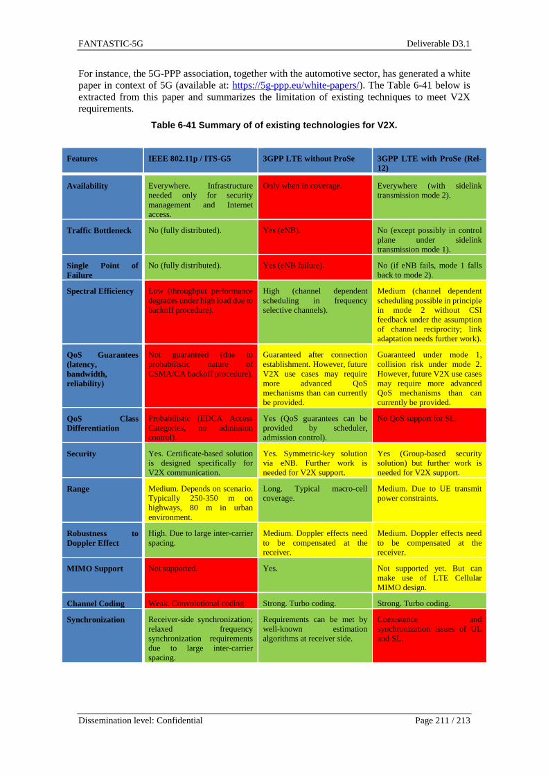
FANTASTIC-5G Deliverable D3.1
Dissemination level: Confidential Page 211 / 213
For instance, the 5G-PPP association, together with the automotive sector, has generated a white paper in context of 5G (available at: https://5g-ppp.eu/white-papers/). The Table 6-41 below is extracted from this paper and summarizes the limitation of existing techniques to meet V2X requirements.
Table 6-41 Summary of of existing technologies for V2X.
Features IEEE 802.11p / ITS-G5 3GPP LTE without ProSe 3GPP LTE with ProSe (Rel-12)
Availability Everywhere. Infrastructure needed only for security management and Internet access.
Only when in coverage. Everywhere (with sidelink transmission mode 2).
Traffic Bottleneck No (fully distributed). Yes (eNB). No (except possibly in control plane under sidelink transmission mode 1).
Single Point of Failure
No (fully distributed). Yes (eNB failure). No (if eNB fails, mode 1 falls back to mode 2).
Spectral Efficiency Low (throughput performance degrades under high load due to backoff procedure).
High (channel dependent scheduling in frequency selective channels).
Medium (channel dependent scheduling possible in principle in mode 2 without CSI feedback under the assumption of channel reciprocity; link adaptation needs further work).
QoS Guarantees (latency, bandwidth, reliability)
Not guaranteed (due to probabilistic nature of CSMA/CA backoff procedure).
Guaranteed after connection establishment. However, future V2X use cases may require more advanced QoS mechanisms than can currently be provided.
Guaranteed under mode 1, collision risk under mode 2. However, future V2X use cases may require more advanced QoS mechanisms than can currently be provided.
QoS Class Differentiation
Probabilistic (EDCA Access Categories, no admission control).
Yes (QoS guarantees can be provided by scheduler, admission control).
No QoS support for SL.
Security Yes. Certificate-based solution is designed specifically for V2X communication.
Yes. Symmetric-key solution via eNB. Further work is needed for V2X support.
Yes (Group-based security solution) but further work is needed for V2X support.
Range Medium. Depends on scenario. Typically 250-350 m on highways, 80 m in urban environment.
Long. Typical macro-cell coverage.
Medium. Due to UE transmit power constraints.
Robustness to Doppler Effect
High. Due to large inter-carrier spacing.
Medium. Doppler effects need to be compensated at the receiver.
Medium. Doppler effects need to be compensated at the receiver.
MIMO Support Not supported. Yes. Not supported yet. But can make use of LTE Cellular MIMO design.
Channel Coding Weak. Convolutional coding. Strong. Turbo coding. Strong. Turbo coding.
Synchronization Receiver-side synchronization; relaxed frequency synchronization requirements due to large inter-carrier spacing.
Requirements can be met by well-known estimation algorithms at receiver side.
Coexistence and synchronization issues of UL and SL.

FANTASTIC-5G Deliverable D3.1
Dissemination level: Confidential Page 212 / 213
Pilot Design Combination of preamble and comb pilots. Channel estimation is challenged by high mobility, especially for long data packets. Improved by blind channel estimation capabilities.
Well-suited pilot design for LTE mobility scenarios in DL (scattered pilots), suboptimal in UL (midamble).
Suboptimal midamble pilot scheme in SC-FDMA for highly time-variant channels. Higher mobility on SL, compared to UL, makes the pilot scheme even more unsuitable for time interpolation to cope with channel time variance.
As a result, and also to try to capture the connected car market, the 3GPP has started to define a V2X solution, in context of Rel13/Rel. 14, leveraging the previous work on Proximity Services (Prose, a.k.a D2D for the physical layer).
6.10.2.5 V2X in 3GPP
3GPP is pushing full steam two studies in parallel for enhancing the LTE to support V2X. The two study items (SI) are running in two different groups within 3GPP: SA1 which mostly studies the use cases related to V2X and defines priority and general requirements for each use case (such as latency, maximum speed, packet size etc.) and RAN1 that study the physical enhancement required to supports the requirements listed by SA. In RAN1, the study has started and already completed the V2V part (V2I and V2P is still on-going in Q1 2016).
As a result, in Dec 2015, the RAN plenary has agreed to initiate a work item dedicated to V2V, following the outcome of the study item. Both SI and WI will be thus progressing in parallel during 2016.
All the information about the study item assumptions; technical proposals and simulation assumptions is captured in the technical report 36.885 “Study on LTE-based V2X Services” [TR36.885].

FANTASTIC-5G Deliverable D3.1
Dissemination level: Confidential Page 213 / 213