preliminary results of the structural analysis · number 6 through 10 would be in one cryostat...
TRANSCRIPT

Feasibility Study of a Neutrino SourceBased on a Muon Storage Ring
Target Magnet System Mechanical Design
Preliminary Results of the Structural Analysis
A suggested design concept groups theCo-Fe poles, Mercury jet hardware,tungsten carbide ball shielding, andcopper coils in a cassette that would beinserted in the bore of thesuperconducting coil cryostat. Coilsnumber 6 through 10 would be in onecryostat assembly, and the rest would begrouped in two or three per cryostat. Coil#6, Super #1 could have CS Model coiltype conductors and layer winding. Thepraying hand joints could be alignedradially between Super #1 and 2 andmore conventionally at the other end ofcoil #6
The electromagnetic model providesfields and forces for the structural model. With the use of orthotropic materials, the details of conductorcross sections can be simulated. We have local models of square CICC's (ITER/CS Model coil) and hollowcopper conductors (C-Mod and IGNITOR) that can be used for the stress multipliers. FNML has publishedsome papers on their Bitter magnet designs that I would use for evaluation of that copper option..
The design Tresca stress value (Sm) at 4K is:
500 MPa for steel600 MPa for Incoloy 908
which gives the following static stress limits at 4Kfor normal operation:
Primary membrane stress < 500 MPa(steel),< 600 MPa (Incoloy 908)
Primary membrane plus bending stress <650 MPa(steel), < 780 (Incoloy 908)
Flux Lines
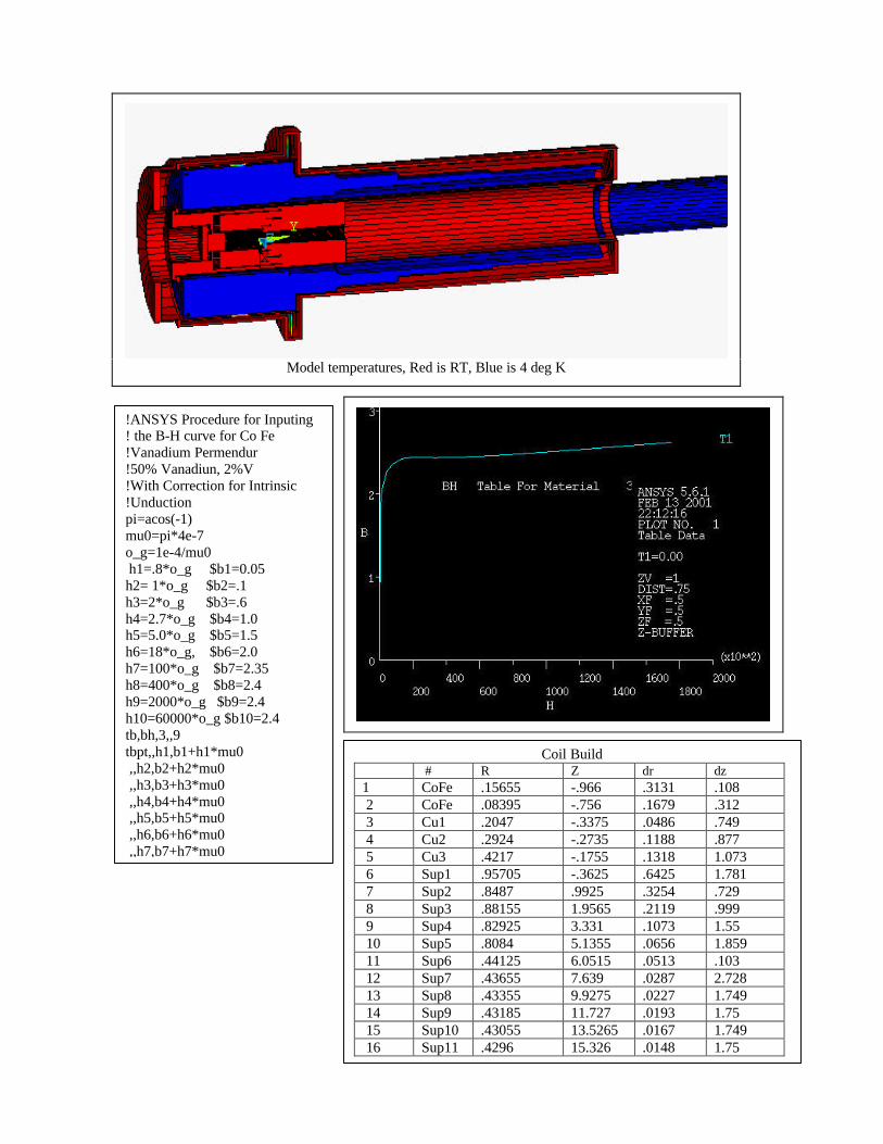
Model temperatures, Red is RT, Blue is 4 deg K
!ANSYS Procedure for Inputing! the B-H curve for Co Fe!Vanadium Permendur!50% Vanadiun, 2%V!With Correction for Intrinsic!Unductionpi=acos(-1)mu0=pi*4e-7o_g=1e-4/mu0 h1=.8*o_g $b1=0.05h2= 1*o_g $b2=.1h3=2*o_g $b3=.6h4=2.7*o_g $b4=1.0h5=5.0*o_g $b5=1.5h6=18*o_g, $b6=2.0h7=100*o_g $b7=2.35h8=400*o_g $b8=2.4h9=2000*o_g $b9=2.4h10=60000*o_g $b10=2.4tb,bh,3,,9tbpt,,h1,b1+h1*mu0 ,,h2,b2+h2*mu0 ,,h3,b3+h3*mu0 ,,h4,b4+h4*mu0 ,,h5,b5+h5*mu0 ,,h6,b6+h6*mu0 ,,h7,b7+h7*mu0
Coil Build # R Z dr dz
1 CoFe .15655 -.966 .3131 .108 2 CoFe .08395 -.756 .1679 .312 3 Cu1 .2047 -.3375 .0486 .749 4 Cu2 .2924 -.2735 .1188 .877 5 Cu3 .4217 -.1755 .1318 1.073 6 Sup1 .95705 -.3625 .6425 1.781 7 Sup2 .8487 .9925 .3254 .729 8 Sup3 .88155 1.9565 .2119 .999 9 Sup4 .82925 3.331 .1073 1.55 10 Sup5 .8084 5.1355 .0656 1.859 11 Sup6 .44125 6.0515 .0513 .103 12 Sup7 .43655 7.639 .0287 2.728 13 Sup8 .43355 9.9275 .0227 1.749 14 Sup9 .43185 11.727 .0193 1.75 15 Sup10 .43055 13.5265 .0167 1.749 16 Sup11 .4296 15.326 .0148 1.75
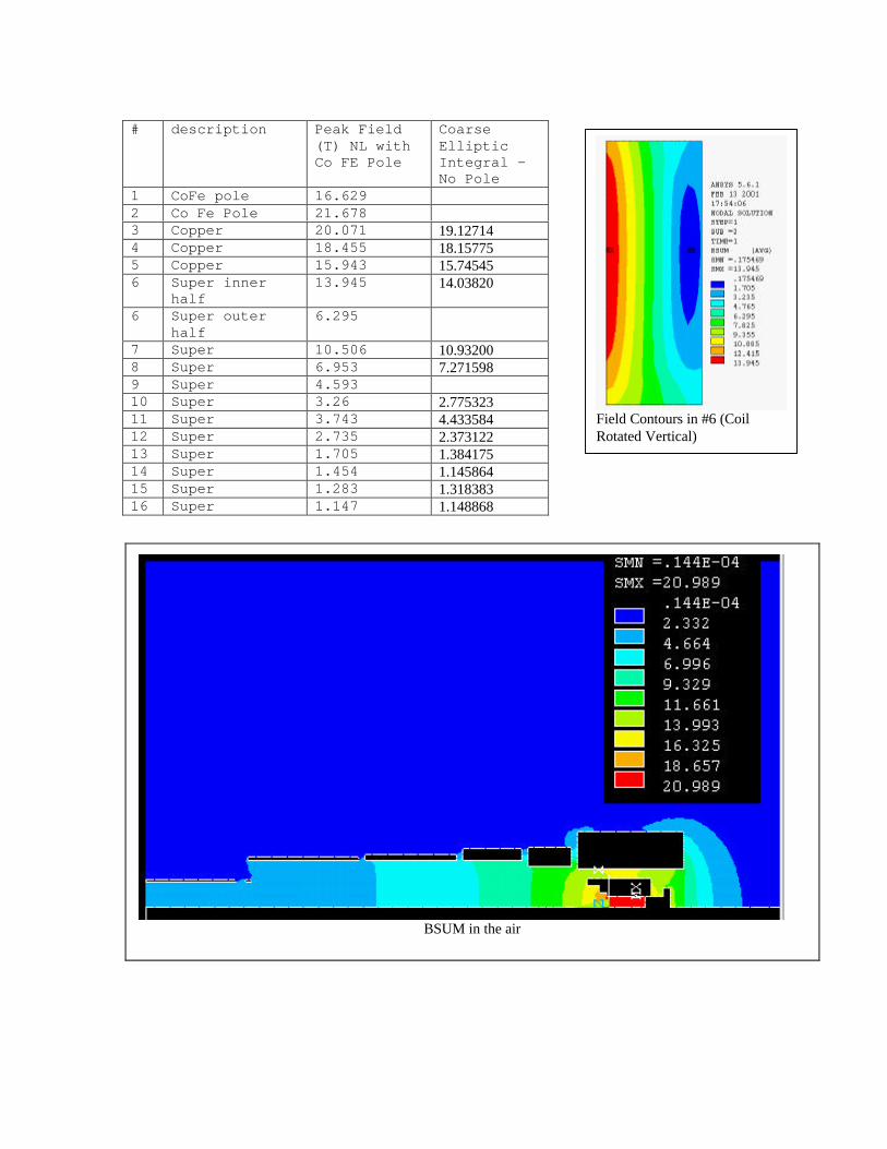
# description Peak Field(T) NL withCo FE Pole
CoarseEllipticIntegral -No Pole
1 CoFe pole 16.6292 Co Fe Pole 21.6783 Copper 20.071 19.127144 Copper 18.455 18.157755 Copper 15.943 15.745456 Super inner
half13.945 14.03820
6 Super outerhalf
6.295
7 Super 10.506 10.932008 Super 6.953 7.2715989 Super 4.59310 Super 3.26 2.77532311 Super 3.743 4.43358412 Super 2.735 2.37312213 Super 1.705 1.38417514 Super 1.454 1.14586415 Super 1.283 1.31838316 Super 1.147 1.148868
BSUM in the air
Field Contours in #6 (CoilRotated Vertical)
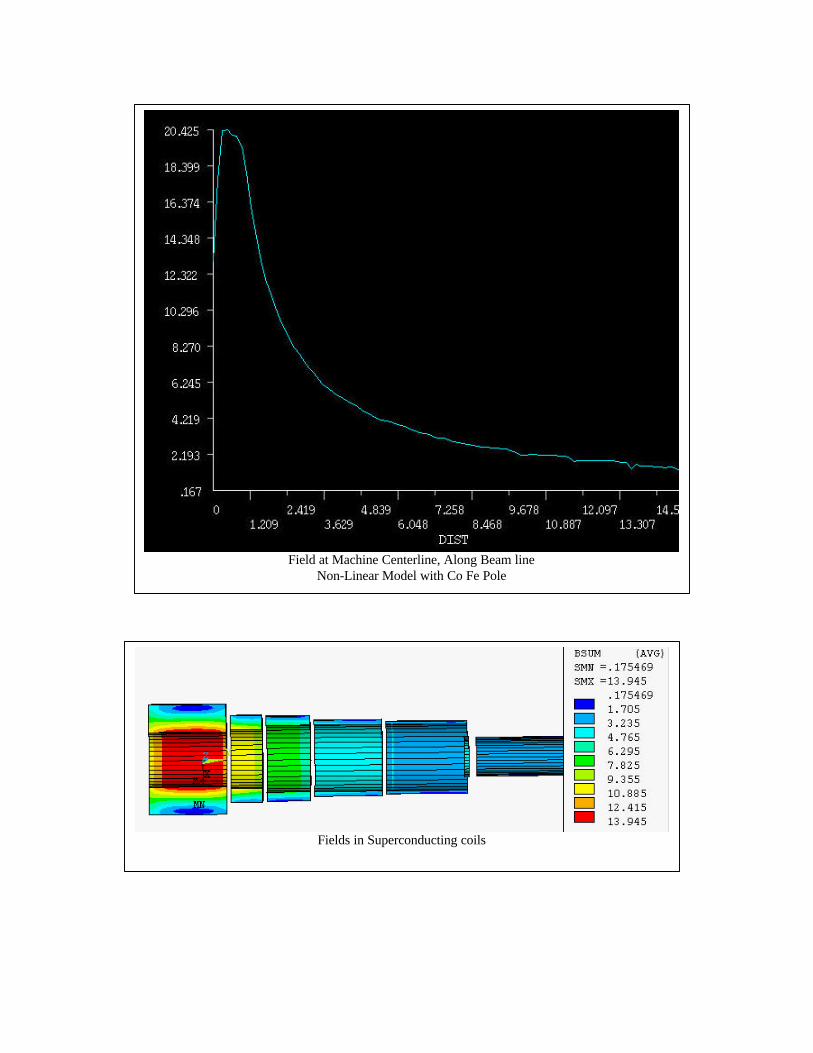
Field at Machine Centerline, Along Beam lineNon-Linear Model with Co Fe Pole
Fields in Superconducting coils
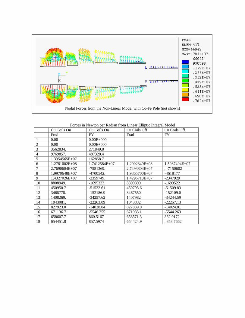
Forces in Newton per Radian from Linear Elliptic Integral ModelCu Coils On Cu Coils On Cu Coils Off Cu Coils OffFrad FY Frad FY
1 0.00 0.00E+0002 0.00 0.00E+0003 3562834. 271849.84 9769857. 487328.45 1.3354565E+07 162858.76 1.2781002E+08 1.7412584E+07 1.2902349E+08 1.5937494E+077 2.7690604E+07 -7581369. 2.7493804E+07 , -71506028 1.9970648E+07 -4700542. 1.9865700E+07 -46181779 1.4327026E+07 -2359749. 1.4296713E+07 -234792910 8808949. -1695323. 8800899 -169352211 450950.7 -51522.61 450793.6 -51509.8312 3468778. -152186.9 3467550 -152109.013 1408269. -34257.62 1407982 -34244.5914 1043981. -22263.09 1043832 -22257.1315 827923.0 -14028.04 827839.0 -14024.8116 671136.7 -5546.255 671085.1 -5544.26317 658607.7 860.5167 658571.3 862.017218 654451.8 857.5974 654424.9 , 858.7662
Nodal Forces from the Non-Linear Model with Co-Fe Pole (not shown)
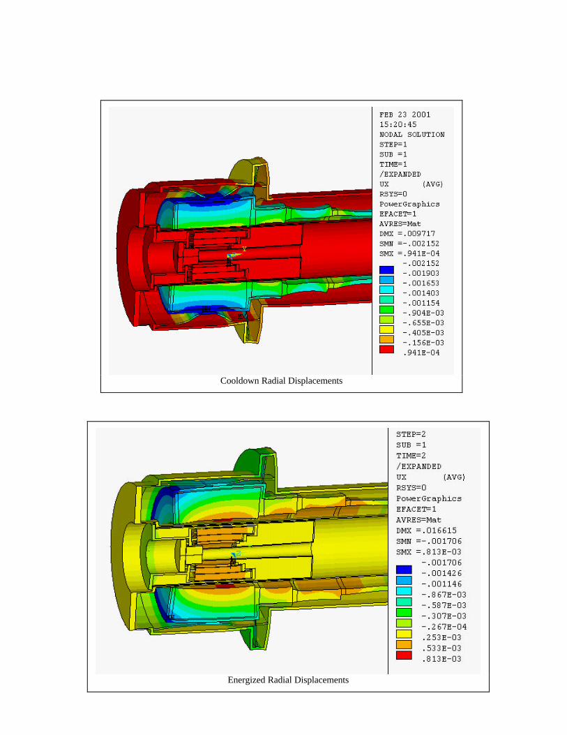
Cooldown Radial Displacements
Energized Radial Displacements
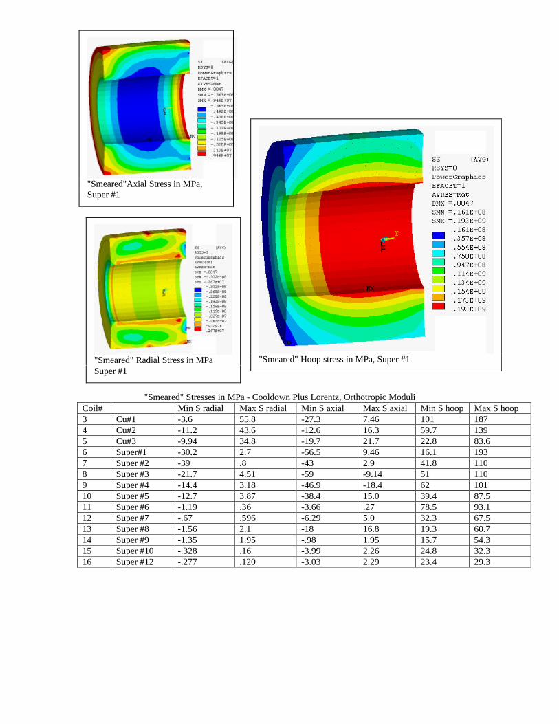
"Smeared" Stresses in MPa - Cooldown Plus Lorentz, Orthotropic ModuliCoil# Min S radial Max S radial Min S axial Max S axial Min S hoop Max S hoop3 Cu#1 -3.6 55.8 -27.3 7.46 101 1874 Cu#2 -11.2 43.6 -12.6 16.3 59.7 1395 Cu#3 -9.94 34.8 -19.7 21.7 22.8 83.66 Super#1 -30.2 2.7 -56.5 9.46 16.1 1937 Super #2 -39 .8 -43 2.9 41.8 1108 Super #3 -21.7 4.51 -59 -9.14 51 1109 Super #4 -14.4 3.18 -46.9 -18.4 62 10110 Super #5 -12.7 3.87 -38.4 15.0 39.4 87.511 Super #6 -1.19 .36 -3.66 .27 78.5 93.112 Super #7 -.67 .596 -6.29 5.0 32.3 67.513 Super #8 -1.56 2.1 -18 16.8 19.3 60.714 Super #9 -1.35 1.95 -.98 1.95 15.7 54.315 Super #10 -.328 .16 -3.99 2.26 24.8 32.316 Super #12 -.277 .120 -3.03 2.29 23.4 29.3
"Smeared"Axial Stress in MPa,Super #1
"Smeared" Radial Stress in MPaSuper #1
"Smeared" Hoop stress in MPa, Super #1

"Smeared" Stresses - No Thermal, Uniform Modulus.Max S hoop Min S hoop Min S axial Max S axial
6 183 42.3 -66.4 3.87 149 76 -74.2 -18 120 72.5 -58.5 -12.69 99.2 67.1 -51.8 -9.2510 86.5 42.4 -44.6 21.811 92.6 79.3 -3.58 .312 67.3 32.6 -6.6 5.513 58.3 21.7 -23 2214 52.1 17.8 -20.7 20.315 31.7 25.1 -4.1 .2416 28.7 23.8 -3.1 2.4
Radial Stresses in Copper Coils - Provision for parting planes, will relieve radial tension.
Axial Stresses in Super #14-16 - These are bending Stresses and will be relieved with externalBobbins.
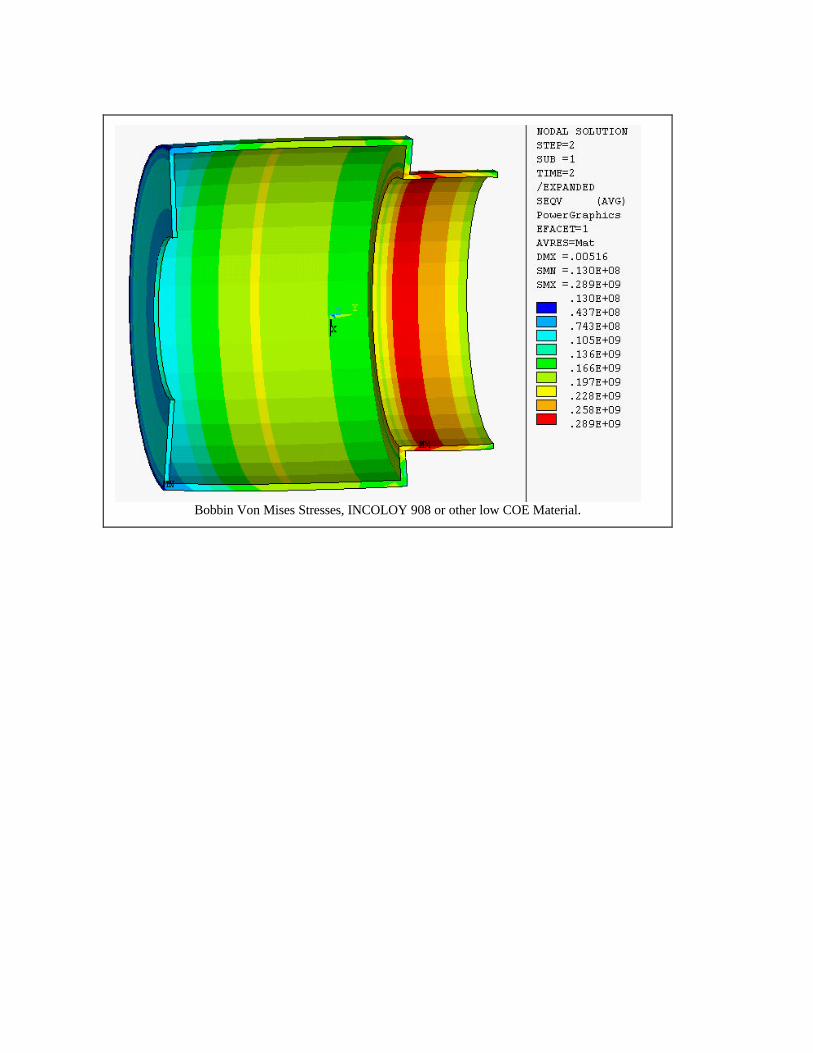
Bobbin Von Mises Stresses, INCOLOY 908 or other low COE Material.
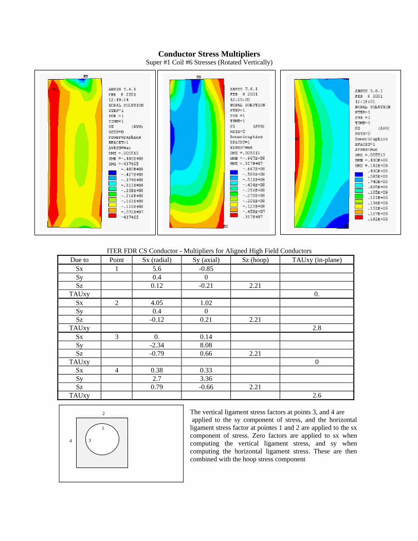
Conductor Stress MultipliersSuper #1 Coil #6 Stresses (Rotated Vertically)
ITER FDR CS Conductor - Multipliers for Aligned High Field ConductorsDue to Point Sx (radial) Sy (axial) Sz (hoop) TAUxy (in-plane)
Sx 1 5.6 -0.85Sy 0.4 0Sz 0.12 -0.21 2.21
TAUxy 0.Sx 2 4.05 1.02Sy 0.4 0Sz -0.12 0.21 2.21
TAUxy 2.8Sx 3 0. 0.14Sy -2.34 8.08Sz -0.79 0.66 2.21
TAUxy 0Sx 4 0.38 0.33Sy 2.7 3.36Sz 0.79 -0.66 2.21
TAUxy 2.6
The vertical ligament stress factors at points 3, and 4 are applied to the sy component of stress, and the horizontalligament stress factor at pointes 1 and 2 are applied to the sxcomponent of stress. Zero factors are applied to sx whencomputing the vertical ligament stress, and sy whencomputing the horizontal ligament stress. These are thencombined with the hoop stress component
34
1
2

Arrangement of Praying Hand Joints
I am suggesting that the praying hand joints be aligned radially in the space between super #1 and #2,That these joints only be used for a high field inner set of windings in Super #1. The inner lead for the coilwould break out at the other end, and thus the mechanism for talking its tension and partially equilibratingit with the outer turn lead could be made up where there is ample space. Praying hand tension links areaccessible and could be something like a turnbuckle connecting the two lugs shown in the diagram below. Ishow an outer cylinder for Super#1 to provide a mounting point for the axial and radial support rods. Thespace provided for the joints could also be used for the radial support rods that are shown. These mayrequire a Belleville stack if they are not long enough. A tangent array of rods like we used on GEM mayalso be possible depending upon the positions and number of praying hand joints. The praying hand modelused in the plot below is actually the same model segment used in the CS model coil analyses - but rotated90 degrees.
The outer cylinder for Super#1 also provides restraint point for the joints. The four joints shown wouldallow 8 one - in - hand layers of "high heat flux" conductor. There appears to be space for more joints if
needed. The field in this space is about 3 Tesla. I extend the outer cylinder, with a step down to the OD ofSuper#2 to provide hoop support for this coil as well.
Because of the way the joints butt, we should simply allow the winding errors to accumulate from the IDand expect a variation in OD to be adjusted with a small change in current.