preliminary sizing of vertical take-off rocket-based
TRANSCRIPT
NASA/TM-2001-210668
Preliminary Sizing of Vertical Take-Off Rocket-Based Combined-Cycle Powered Launch Vehicles
Joseph M. Roche Glenn Research Center, Cleveland, Ohio
David R. McCurdy Dynacs Engineering Company, Inc., Brook Park, Ohio
January 2001
The NASA STI Program Office ... in Profile
Since its founding, NASA has been dedicated to the advancement of aeronautics and space science. The NASA Scientific and Technical Information (STI) Program Office plays a key part in helping NASA maintain this important role.
The NASA STI Program Office is operated by Langley Research Center, the Lead Center for NASA's scientific and technical information. The NASA STI Program Office provides access to the NASA STI Database, the largest collection of aeronautical and space science STI in the world. The Program Office is also NASA's institutional mechanism for disseminating the results of its research and development activities. These results are published by NASA in the NASA STI Report Series, which includes the following report types:
• TECHNICAL PUBLICATION. Reports of completed research or a major Significant phase of research that present the results of NASA programs and include extensive data or theoretical analysis. Includes compilations of significant scientific and technical data and information deemed to be of continuing reference value. NASA's counterpart of peerreviewed formal professional papers but has less stringent limitations on manuscript length and extent of graphic presentations.
• TECHNICAL MEMORANDUM. Scientific and technical findings that are preliminary or of specialized interest, e.g., quick release reports, working papers, and bibliographies that contain minimal annotation. Does not contain extensive analysis.
• CONTRACTOR REPORT. Scientific and technical findings by NASA-sponsored contractors and grantees.
• CONFERENCE PUBLICATION. Collected papers from scientific and technical conferences, symposia, seminars, or other meetings sponsored or cosponsored by NASA.
• SPECIAL PUBLICATION. Scientific, technical, or historical information from NASA programs, projects, and missions, often concerned with subjects having substantial public interest.
• TECHNICAL TRANSLATION. Englishlanguage translations of foreign scientific and technical material pertinent to NASA's mission.
Specialized services that complement the STI Program Office's diverse offerings include creating custom thesauri, building customized data bases, organizing and publishing research results . .. even providing videos.
For more information about the NASA STI Program Office, see the following:
• Access the NASA STI Program Home Page at http://www.sti.nasa.gov
• E-mail your question via the Internet to hel [email protected]
• Fax your question to the NASA Access Help Desk at 301-621-0134
• Telephone the NASA Access Help Desk at 301-621-0390
• Write to: NASA Access Help Desk NASA Center for AeroSpace Information 7121 Standard Drive Hanover, MD 21076
NASA/TM-2001-210668
Preliminary Sizing of Vertical Take-Off Rocket-Based Combined-Cycle Powered Launch Vehicles
Joseph M. Roche Glenn Research Center, Cleveland, Ohio
David R. McCurdy Dynacs Engineering Company, Inc., Brook Park, Ohio
Prepared for the 37th Combustion Subcommittee, 25th Airbreathing Propulsion Subcommittee, and 19th Propulsion Systems Hazards Subcommittee Joint Meeting sponsored by the Joint Army-Navy-Air Force Interagency Propulsion Committee Monterey, California, November 13-17,2000
National Aeronautics and Space Administration
Glenn Research Center
January 2001
This report contains preliminary findings, subject to revision as
analysis proceeds.
Trade names or manufactUrers' names are used in this report for identification only. This usage does not constitute an official endorsement, either expressed or implied, by the National
Aeronautics and Space Administration.
Available from
NASA Center for Aerospace Information 7121 Standard Drive
National Technical Information Service 5285 Port Royal Road Springfield, VA 22100
Price Code: A03 Hanover, MD 21076 Price Code: A03
Available electronically at http: //gltrs.grc.nasa.gov IGLTRS
PRELIMINARY SIZING OF VERTICAL TAKE-OFF ROCKET-BASED COMBINED-CYCLE POWERED LAUNCH VEHICLES
Joseph M. Roche and David R. McCurdy National Aeronautics and Space Administration
Glenn Research Center Cleveland, Ohio 44135
SUMMARY
The task of single-stage-to-orbit has been an elusive goal due to propulsion performance, materials limitations, and complex system integration. Glenn Research Center has begun to assemble a suite of relationships that tie Rocket-Based Combined-Cycle (RBCC) performance and advanced material data into a database for the purpose of preliminary sizing of RBCC-powered launch vehicles. To accomplish this, a near optimum aerodynamic and structural shape was established as a baseline. The program synthesizes a vehicle to meet the mission requirements, tabulates the results, and plots the derived shape. A discussion of the program architecture and an example application is discussed herein .
INTRODUCTION
NASA has developed a three-phased approach to advance access to space. The third phase of this program is known as Generation 3. The Generation 3 type activities include the development of revolutionary propulsion technology. NASA Glenn Research Center (GRC) has been developing Rocket-Based CombinedCycle (RBCC) propulsion as part of this effort. The RBCC propulsion system is a mechanically simple device that has the potential for both reducing vehicle weight and enhancing engine performance. An RBCC propulsion system fueled with hydrogen is ideally suited for single-stage-to-orbit (SSTO) operation. GRC believes that reusable SSTO operation has the potential to significantly reduce launch operation costs.
The RBCC-powered launch vehicle must fly from sea level static conditions to hypersonic speed while in the atmosphere. This resulting operational environment is extremely challenging. Both aeroheating and aeropressure loads will be more severe than those experienced with traditional rocket-powered vehicles. In essence, a trade is done between improved propulsion performance and vehicle structural weight.
NASA GRC developed the GTX vehicle in response to the desire to reduce launch costs. The Bantam program funded by the NASA Marshall Space Flight Center (MSFC) established the launch goals. The key objective was to place a 300 Ib payload into the International Space Station (ISS) orbit. The Bantam mission provided the focus for the GTX development while keeping the vehicle to a minimum size and cost. In tailoring the vehicle/propulsion for the mission, a high thrust-to-weight vertical take-off mission profile was selected. The high thrust-to-weight put the vehicle in the accelerator class, which shortened the duration of the air-breathing operation, minimized aeroheating on the vehicle, and ultimately helped keep the vehicle weight to a minimum.
VEHICLE ARCHITECTURE
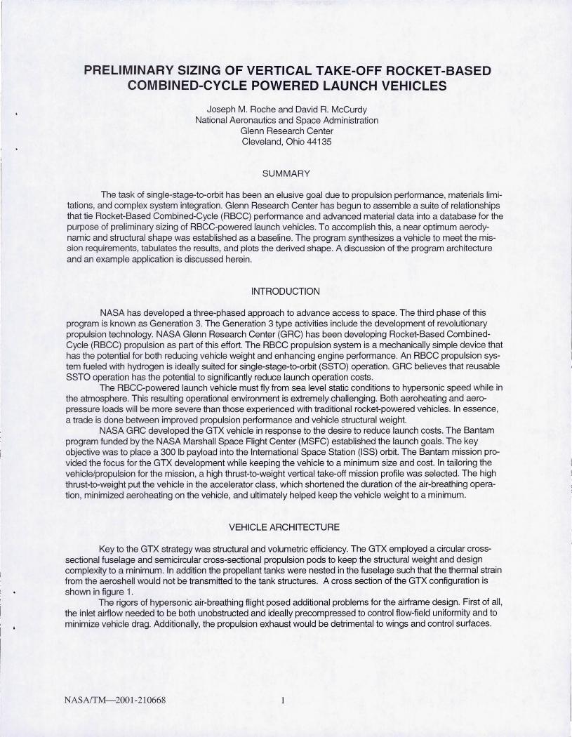
Key to the GTX strategy was structural and volumetric efficiency. The GTX employed a circular crosssectional fuselage and semicircular cross-sectional propulsion pods to keep the structural weight and design complexity to a minimum. In addition the propellant tanks were nested in the fuselage such that the thermal strain from the aeroshell would not be transmitted to the tank structures. A cross section of the GTX configuration is shown in figure 1.
The rigors of hypersonic air-breathing flight posed additional problems for the airframe design. First of all , the inlet airflow needed to be both unobstructed and ideally precompressed to control flow-field uniformity and to minimize vehicle drag. Additionally, the propulsion exhaust would be detrimental to wings and control surfaces.
N ASAffM-200 1-210668 1
Detail B
Forward thrust ring Detail C
Aft thrust ring
Centerbody Cowl
See detail B
Section A-A
Figure 1.-GTX vehicle.
/ Station 3
1.4 ,------------------------------------------------, -- Cylinder (d/(21c+4)
1.2 __ Cone (d/(6+sqrt(1/4c2 + 1 + 1/c)) _________________ ---:;"....,L-__ -j
'" 1.0 ~ Ogive -+- Sphere (d/6) e
~0.8 +-------------------------~~~--~~~~~~--~ C1>
§0.6 +-------------------~~~~~~~~------------~ o >0.4 +-----------~~~~~~~----------------------~
0.2 +-----=~~~~-------------~ 0.0 ~c-----~------~------~------~------~------~
0.0 0.5 1.0 1.5 Radius
2.0 2.5
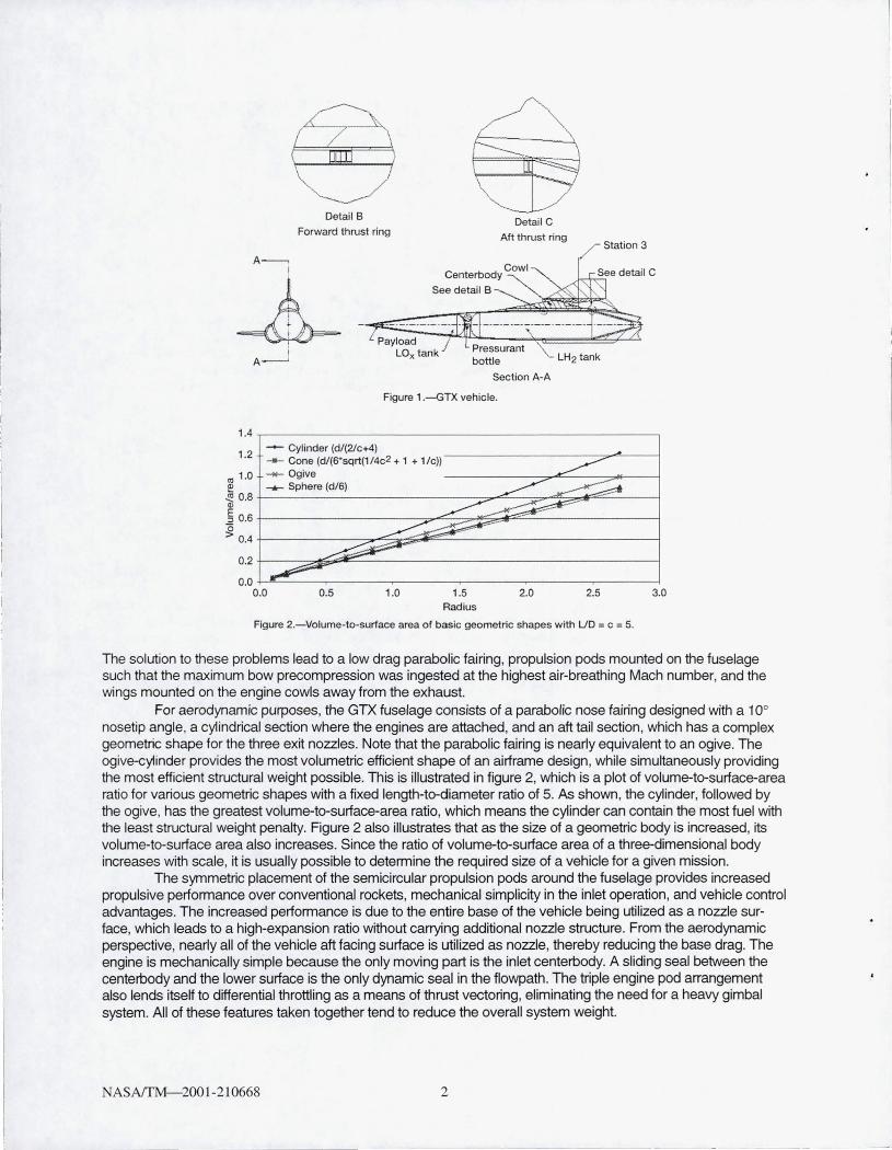
Figure 2.-Volume-to-surface area of basic geometric shapes with UD = c = 5.
3.0
The solution to these problems lead to a low drag parabolic fairing , propulsion pods mounted on the fuselage such that the maximum bow precompression was ingested at the highest air-breathing Mach number, and the wings mounted on the engine cowls away from the exhaust.
For aerodynamic purposes, the GTX fuselage consists of a parabolic nose fairing designed with a 10° nosetip angle, a cylindrical section where the engines are attached, and an aft tail section, which has a complex geometric shape for the three exit nozzles. Note that the parabolic fairing is nearly equivalent to an ogive. The ogive-cylinder provides the most volumetric efficient shape of an airframe design, while simultaneously providing the most efficient structural weight possible. This is illustrated in figure 2, which is a plot of volume-to-surface-area ratio for various geometric shapes with a fixed length-to-diameter ratio of 5. As shown, the cylinder, followed by the ogive, has the greatest volume-to-surface-area ratio, which means the cylinder can contain the most fuel with the least structural weight penalty. Figure 2 also illustrates that as the size of a geometric body is increased, its volume-to-surface area also increases. Since the ratio of volume-to-surface area of a three-dimensional body increases with scale, it is usually possible to determine the required size of a vehicle for a given mission.
The symmetric placement of the semicircular propulsion pods around the fuselage provides increased propulsive performance over conventional rockets, mechanical simplicity in the inlet operation, and vehicle control advantages. The increased performance is due to the entire base of the vehicle being utilized as a nozzle surface, which leads to a high-expansion ratio without carrying additional nozzle structure. From the aerodynamic perspective, nearly all of the vehicle aft facing surface is utilized as nozzle, thereby reducing the base drag. The engine is mechanically simple because the only moving part is the inlet centerbody. A sliding seal between the centerbody and the lower surface is the only dynamic seal in the flowpath. The triple engine pod arrangement also lends itself to differential throttling as a means of thrust vectoring, eliminating the need for a heavy gimbal system. All of these features taken together tend to reduce the overall system weight.
NASAlTM--200 1-210668 2
Utilizing sound engineering principles, all tanks are designed from bodies of revolution, which means there are no discontinuities in the tank shell to allow room for other systems such as landing gear. Landing gear, avionics, and payload are placed either between the tanks or in front of the tank stack. Where abrupt changes in slope occur on the tank profile, such as a conic to a cylinder, or where hardpoint attachments are located, stiff rings are provided to reinforce the tank structure.
The tanks are nested in the fuselage in a near conformal shape that provides the highest volumetric efficiency without violating the outer mold line (OML) and the required aeroshell thickness. For the baseline configuration, the LOx tank is positioned in the forward section of the fairing. It comprises two elliptical bulkheads and a frustum of an ogive. Clearance is reserved between the tank and fuselage for the TPS. Also, dynamic clearance is provided along the length of the tank. The propellant tank also conforms to the fuselage OML. Starting from the aft position, the tank comprises a small elliptical bulkhead attached to a conical section that fits within the tail section . Attached to the conical section is a cylindrical section that conforms to the fuselage cylinder section. Beyond the point where the cylinder section will not fit, a parabolic section is attached that follows the contour of the fairing parabola. Finally, a forward elliptical bulkhead closes out the propellant tank. The tanks are stacked one on top of each other by an intertank adapter.
The tank stack is attached to the fuselage by a series of strut rods at two hardpoint locations on the airframe, which are termed the fore and aft thrust rings. The thrust rings have a dual purpose in that they both provide main attachment for the engines as well as attachment for the tank stack and as such are the primary load path of the entire vehicle. The tank attachment scheme is made in order to minimize thermal stresses between the fuselage and tank stack. The aft attachment is a series of 12 tangential strut rods that provide radial and torsional support while allowing differential radial expansion between the tank and fuselage, as well as provide differential longitudinal expansion without inducing thermal stresses. The forward attachment is a series of 24 offaxis longitudinal struts that provide support in the axial and radial directions. A forward bumper ring is provided at the aft LOx tank bulkhead location in order to prevent tank interference with the fuselage caused from the thermal and aeropressure loads during flight.
PRELIMINARY SIZING
The fraction of propellant by mass needed to complete the mission is known as the propellant fraction required (PFR) and the propellant fraction tanked on the vehicle is known as the propellant fraction available (PFA) . The propellant tanked on the vehicle includes the ascent propellant, the on-orbit circularization burn, deorbit burn, boiloff, off-nominal performance allowance, and residuals. The process of determining if adequate propellant is tanked on the vehicle for a given mission is known as closure. When the PFA in a given size of vehicle is greater than or equal to the PFR, the vehicle is considered closed.
The SSTO mission is extremely challenging from both the propulsion performance and the structural efficiency perspectives. Small perturbations in the dry weight of a vehicle result in large changes in the gross liftoff weight (GLOW). Ratios as high as 10:1 have been observed although the relationship between dry weight and GLOW is highly nonlinear due to the additional fuselage required to contain the requisite propellants.
The initial reference size of the GTX was based on a preliminary weight study, which used historical data from NASA programs and methods from Aircraft Design by Dr. Jan Roskam (ref. 1). Subsequent detailed analyses were performed in order to verify the preliminary weights and provide a basis for any future sizing that might be necessary. The analytical activities included engine performance predictions with RAMSCRAM and RJPA, solid modeling with PRO-E, aerodynamic analysis with APAS, thermal analysis with SINDA and MINIVER, trajectory analysis with OTIS, and structural analysis with NASTRAN.
The vehicle structural weights of the acreage areas were determined by calculating an average areal weight of all the subassemblies and their surface areas. The average areal weights encompass the vehicle components such as tanks, fuselage, and wing boxes as well as the thermal protection system (TPS) for each component. Areal density is dependent upon the ability of the structure to withstand the mechanical and thermal loads throughout the flight. The areal densities for the GTX configuration were determined by finite element analysis (FEA) of the reference vehicle. For the majority of components, the worst load case combination occurred at Mach 10 just after the rocket re-ignition (mode IV) event to accelerate the vehicle out of the atmosphere. For the tanks, the worst load case event was lift-off when the tanks were completely filled. Once all the peak stresses of the various assemblies were determined, a minimum structural weight was established that could withstand the applied loads, using a safety factor on an ultimate stress of 1.5 and 1.1 on yield. These areal weights provided the basis of scaling the vehicle.
NASAfTM-2001-210668 3
SCALING LAWS
The size of a closed vehicle depends on propulsion performance, structural efficiency, packaging efficiency, payload weight, and desired orbit; consequently, it is necessary to alter the size of the vehicle design as these parameters change. However, increasing the scale of a structure also increases the magnitude of induced stresses, which means additional structural weight must be carried in the design. For instance, stress in a pressure vessel is directly proportional to the ratio of its radius over its wall thickness. An increase in radius must be accompanied by an equivalent increase in thickness to maintain constant stress at a constant pressure. This translates into increased areal weight. Therefore, how the relationship between stress and geometric scale effect the overall weight of the GTX vehicle must be carefully considered when determining its required size. In addition, vehicle design adjustments are necessary when large changes in scale are needed, because weight changes by the cube of the scale factor where lift and thrust change by the square of the scale factor.
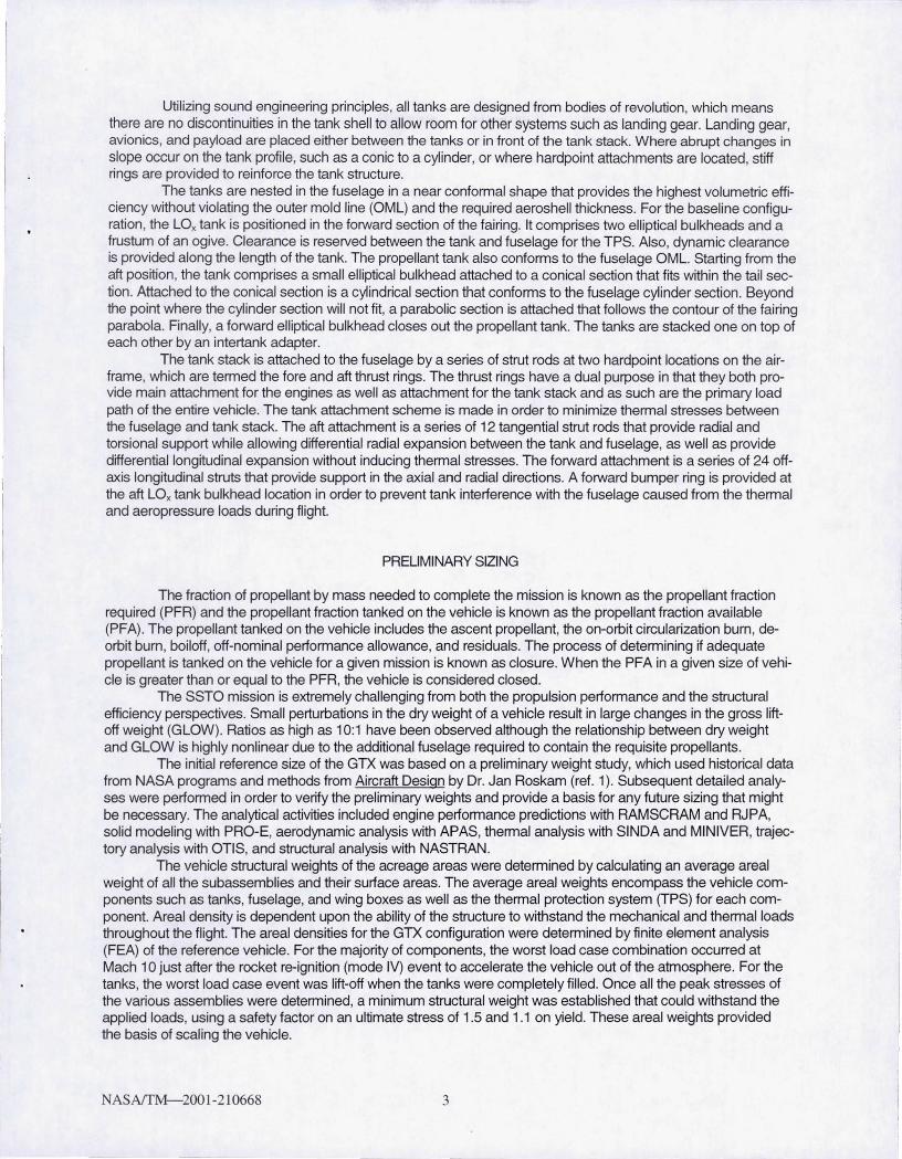
Once scaling effects on weight were understood from the detailed structural analysis of the GTX reference vehicle, then weight factors and parametric relationships were developed in order to perform photographic scaling. Table I summarizes the parametric relationships of the main vehicle components. In addition, a set of equations was established for the GTX configuration that relates vehicle scale and tank volume with fuselage skin, stringer, TPS, and tank skin thickness. In order to automate the closure calculations, the weight and thickness relationships were input to a spreadsheet, known as the GTXSizer. The various areal densities determined from the analysis effort along with additional areal densities of TPS materials were put into the spreadsheet. The GTXSizer was then used to predict the revised size of the 300-lb-payload vehicle.
TABLE I.-GTX WEIGHT FACTOR PARAMETERS
Item Weight Multiplier Surface Area
current U D Fairing Sf*
reference U D
current UD Cylinder Plug Sf *
reference UD
Nozzle Sf
Thrust Rings Sf * Bf
TPS Thickness (current Mach no.)
Th ickness (Mach no.= 10)
Tanks Sf
Wings and Tail 1
Engine 1
Equipment current vehicle volume reference veh icle volume
Notes: Sf = Scale Factor Bf = Beam Shape Factor
The GTXSizer is arranged such that the nosetip-to-cowl lip length (L) can be adjusted while maintaining a fixed body diameter (0). This is accomplished by adjusting the cylinder plug length , as illustrated in figure 3. When this feature is used, the areal weights of the nose vary with scale and the change in L. As the plug length is increased, the nose fairing overall bending moment increases; however, since the body diameter has remained constant, the structural mass must be increased. The areal weights of the skin and stringer increase as a ratio of the current UO to the reference vehicle UO. Along with the areal weights, the shell thickness also increases as a linear function of the vehicle scale multiplied by the UO ratio. This thickness change is accounted for in the GTXSizer because it reduces the available internal volume for propellant and oxidant.
Since volumetric efficiency of the GTX configuration is dependent on the depth of the thrust rings, a structural analysis was performed to determine the necessary cross sections based on a simple I-beam
N AS AffM-200 1-21 0668 4
-~~ --.-. -- -
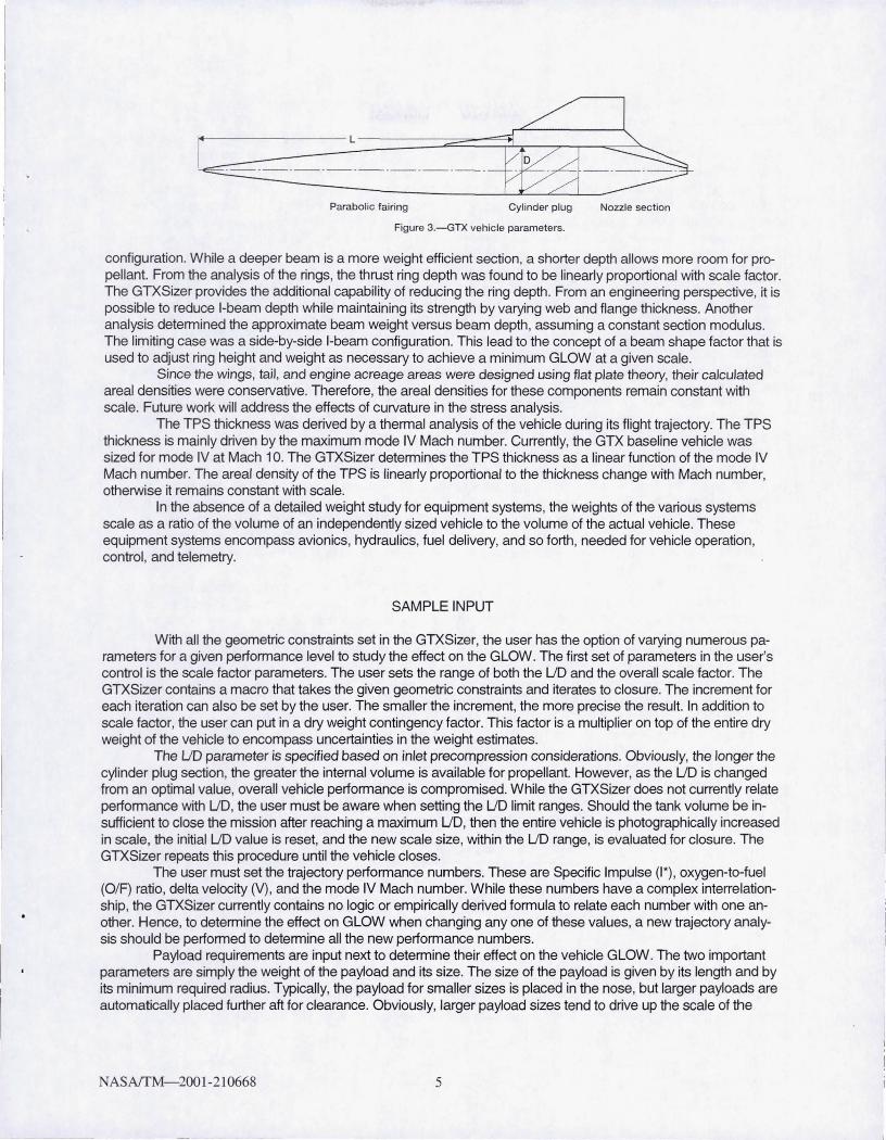
Parabolic fairing Cylinder plug Nozzle sect ion
Figure 3.-GTX vehic le parameters.
configuration. While a deeper beam is a more weight efficient section, a shorter depth allows more room for propellant. From the analysis of the rings, the thrust ring depth was found to be linearly proportional with scale factor. The GTXSizer provides the additional capability of reducing the ring depth. From an engineering perspective, it is possible to reduce I-beam depth while maintaining its strength by varying web and flange thickness. Another analysis determined the approximate beam weight versus beam depth, assuming a constant section modulus. The limiting case was a side-by-side I-beam configuration. This lead to the concept of a beam shape factor that is used to adjust ring height and weight as necessary to achieve a minimum GLOW at a given scale.
Since the wings, tail, and engine acreage areas were designed using flat plate theory, their calculated areal densities were conservative. Therefore, the areal densities for these components remain constant with scale. Future work will address the effects of curvature in the stress analysis.
The TPS thickness was derived by a thermal analysis of the vehicle during its flight trajectory. The TPS thickness is mainly driven by the maximum mode IV Mach number. Currently, the GTX baseline vehicle was sized for mode IV at Mach 10. The GTXSizer determines the TPS thickness as a linear function of the mode IV Mach number. The areal density of the TPS is linearly proportional to the thickness change with Mach number, otherwise it remains constant with scale.
In the absence of a detailed weight study for equipment systems, the weights of the various systems scale as a ratio of the volume of an independently sized vehicle to the volume of the actual vehicle. These equipment systems encompass avionics, hydraulics, fuel delivery, and so forth, needed for vehicle operation, control, and telemetry.
SAMPLE INPUT
With all the geometric constraints set in the GTXSizer, the user has the option of varying numerous parameters for a given performance level to study the effect on the GLOW. The first set of parameters in the user's control is the scale factor parameters. The user sets the range of both the UD and the overall scale factor. The GTXSizer contains a macro that takes the given geometric constraints and iterates to closure. The increment for each iteration can also be set by the user. The smaller the increment, the more precise the result. In addition to scale factor, the user can put in a dry weight contingency factor. This factor is a multiplier on top of the entire dry weight of the vehicle to encompass uncertainties in the weight estimates.
The UD parameter is specified based on inlet precompression considerations. Obviously, the longer the cyl inder plug section, the greater the internal volume is available for propellant. However, as the UD is changed from an optimal value, overall vehicle performance is compromised. While the GTXSizer does not currently relate performance with UD, the user must be aware when setting the UD limit ranges. Should the tank volume be insufficient to close the mission after reaching a maximum UD, then the entire vehicle is photographically increased in scale, the initial UD value is reset, and the new scale size, within the UD range, is evaluated for closure. The GTXSizer repeats this procedure until the vehicle closes.
The user must set the trajectory performance numbers. These are Specific Impulse (1 *), oxygen-to-fuel (OfF) ratio, delta velocity (V), and the mode IV Mach number. While these numbers have a complex interrelationship, the GTXSizer currently contains no logic or empirically derived formula to relate each number with one another. Hence, to determine the effect on GLOW when changing anyone of these values, a new trajectory analysis should be performed to determine all the new performance numbers.
Payload requirements are input next to determine their effect on the vehicle GLOW. The two important parameters are simply the weight of the payload and its size. The size of the payload is given by its length and by its minimum required radius. Typically, the payload for smaller sizes is placed in the nose, but larger payloads are automatically placed further aft for clearance. Obviously, larger payload sizes tend to drive up the scale of the
N ASAffM- 200 1-210668 5
vehicle which drives up the GLOW. Although not a user input, it warrants mention that the landing gear envelope is also provided automatically.
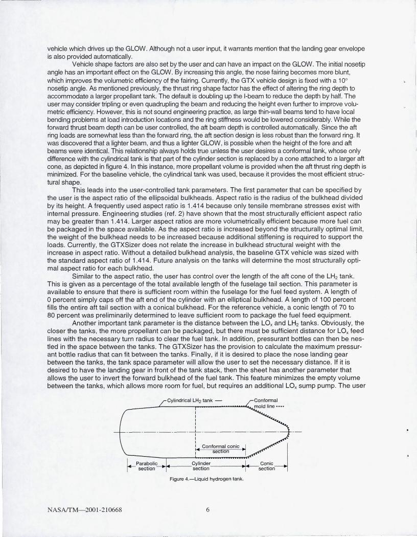
Vehicle shape factors are also set by the user and can have an impact on the GLOW. The initial nosetip angle has an important effect on the GLOW. By increasing this angle, the nose fairing becomes more blunt, which improves the volumetric efficiency of the fairing. Currently, the GTX vehicle design is fixed with a 10° nosetip angle. As mentioned previously, the thrust ring shape factor has the effect of altering the ring depth to accommodate a larger propellant tank. The default is doubling up the I-beam to reduce the depth by half. The user may consider tripling or even quadrupling the beam and reducing the height even further to improve volumetric efficiency. However, this is not sound engineering practice, as large thin-wall beams tend to have local bending problems at load introduction locations and the ring stiffness would be lowered considerably. While the forward thrust beam depth can be user controlled, the aft beam depth is controlled automatically. Since the aft ring loads are somewhat less than the forward ring, the aft section design is less robust than the forward ring. It was discovered that a lighter beam, and thus a lighter GLOW, is possible when the height of the fore and aft beams were identical. This relationship always holds true unless the user desires a conformal tank, whose only difference with the cylindrical tank is that part of the cylinder section is replaced by a cone attached to a larger aft cone, as depicted in figure 4. In this instance, more propellant volume is provided when the aft thrust ring depth is minimized. For the baseline vehicle, the cylindrical tank was used, because it provides the most efficient structural shape.
This leads into the user-controlled tank parameters. The first parameter that can be specified by the user is the aspect ratio of the ellipsoidal bulkheads. Aspect ratio is the radius of the bulkhead divided by its height. A frequently used aspect ratio is 1.414 because only tensile membrane stresses exist with internal pressure. Engineering studies (ref. 2) have shown that the most structurally efficient aspect ratio may be greater than 1 .414. Larger aspect ratios are more volumetrically efficient because more fuel can be packaged in the space available . As the aspect ratio is increased beyond the structurally optimal limit, the weight of the bulkhead needs to be increased because additional stiffening is required to support the loads. Currently, the GTXSizer does not relate the increase in bulkhead structural weight with the increase in aspect ratio. Without a detailed bulkhead analysis, the baseline GTX vehicle was sized with the standard aspect ratio of 1.414. Future analysis on the tanks will determine the most structurally optimal aspect ratio for each bulkhead.
Similar to the aspect ratio , the user has control over the length of the aft cone of the LH2 tank. This is given as a percentage of the total available length of the fuselage tail section . This parameter is available to ensure that there is sufficient room within the fuselage for the fuel feed system . A length of o percent simply caps off the aft end of the cylinder with an elliptical bulkhead. A length of 100 percent fills the entire aft tail section with a conical bulkhead. For the reference vehicle, a conic length of 70 to 80 percent was preliminarily determined to leave sufficient room to package the fuel feed equipment.
Another important tank parameter is the distance between the LOx and LH2 tanks. Obviously, the closer the tanks, the more propellant can be packaged, but there must be sufficient distance for LOx feed lines with the necessary turn radius to clear the fuel tank. In addition , pressurant bottles can then be nestled in the space between the tanks. The GTXSizer has the provision to calculate the maximum pressurant bottle radius that can fit between the tanks. Finally, if it is desired to place the nose landing gear between the tanks, the tank space parameter will allow the user to set the necessary distance. If it is desired to have the landing gear in front of the tank stack, then the sheet has another parameter that allows the user to invert the forward bulkhead of the fuel tank. This feature minimizes the empty volume between the tanks , which allows more room for fuel , but requires an additional LOx sump pump. The user
N AS AffM-200 1-210668
I I I I I
-------- ---- -----~---------------------I I I I Conformal conic I sec Ion
1 _ Parabolic'--J.w-___ Cylinder _____ --;~--. r- section section
Figure 4.-Liquid hydrogen tank.
6
- - - --- - ---- -- ---- ----- -- -------
must exercise engineering judgement in order to ensure there is sufficient room elsewhere for pressurant bottles and pumps.
The final parameter for the tanks is the auxiliary fuel tank provision. When used, this feature places an additional fuel tank in the forward compartment of the fuselage. The user has the option of specifying the total amount of volume in this tank as a percentage of the overall fuel volume. The GTXSizer will then scale the vehicle to its minimum GLOW until the percentage of fuel in the auxiliary tank at least equals the specified value. This feature is best used in larger class vehicles with larger size payloads because it utilizes the empty volume in the vehicle nose. For smaller payload sizes, this feature may actually increase the GLOW because the vehicle may need to be increased in scale to achieve the desired fuel percentage in each tank. Regardless of the effects on the GLOW, this feature also provides some control over the location of the vehicle's wet and dry center of gravity (c.g.). At lift-off, the vehicle is in vertical flight where stability is best maintained when the c.g. is in front of the center of pressure. After the vehicle pitches over for horizontal flight, trim penalties are reduced when the c.g. is closer to the center of pressure. By using a split fuel tank arrangement with the proper allocation of fuel in each, it is possible to control the c.g. of the vehicle for both vertical and horizontal flight. As fuel is depleted in the forward tank, the c.g. shifts aft, enabling easier control of the vehicle when it switches to horizontal flight.
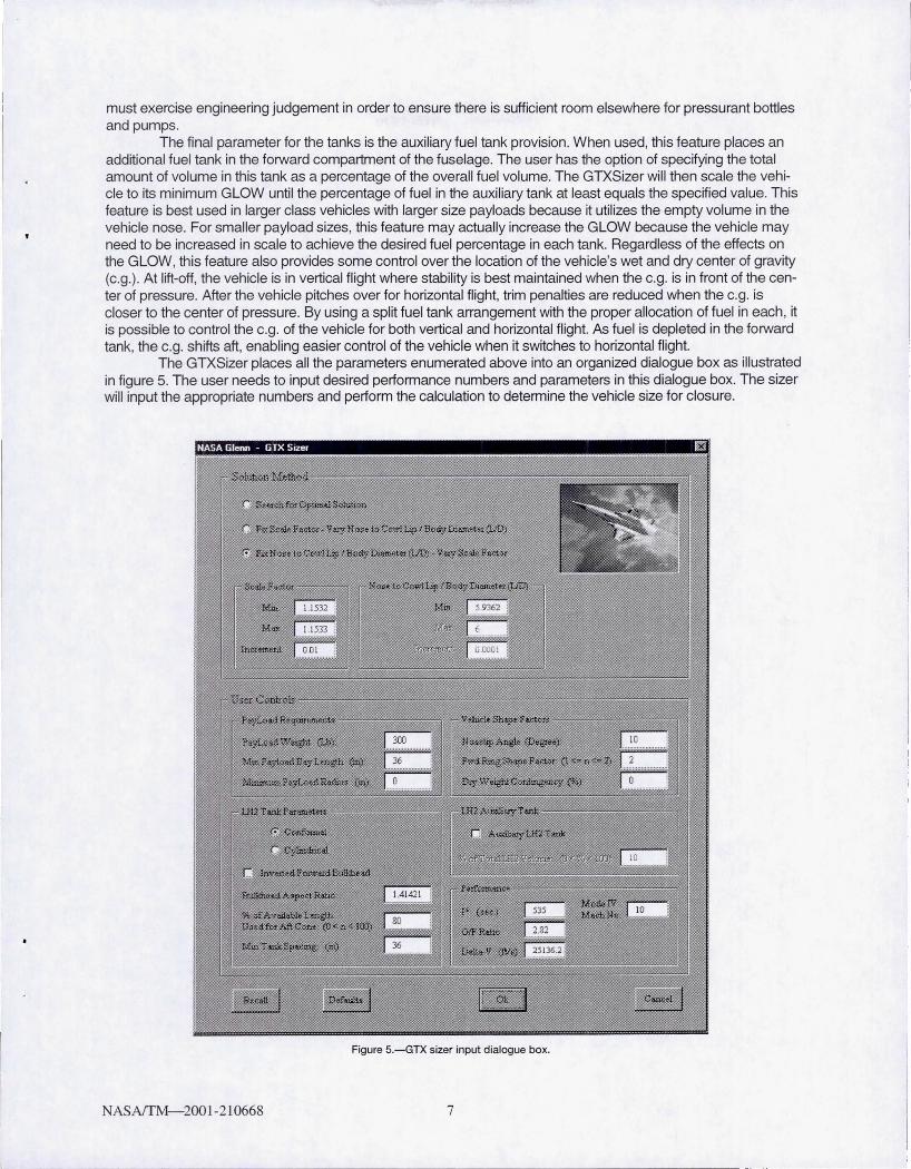
The GTXSizer places all the parameters enumerated above into an organized dialogue box as illustrated in figure 5. The user needs to input desired performance numbers and parameters in this dialogue box. The sizer will input the appropriate numbers and perform the calculation to determine the vehicle size for closure.
Figure 5.-GTX sizer input dialogue box.
NASAffM-2001-210668 7
SAMPLE OUTPUT
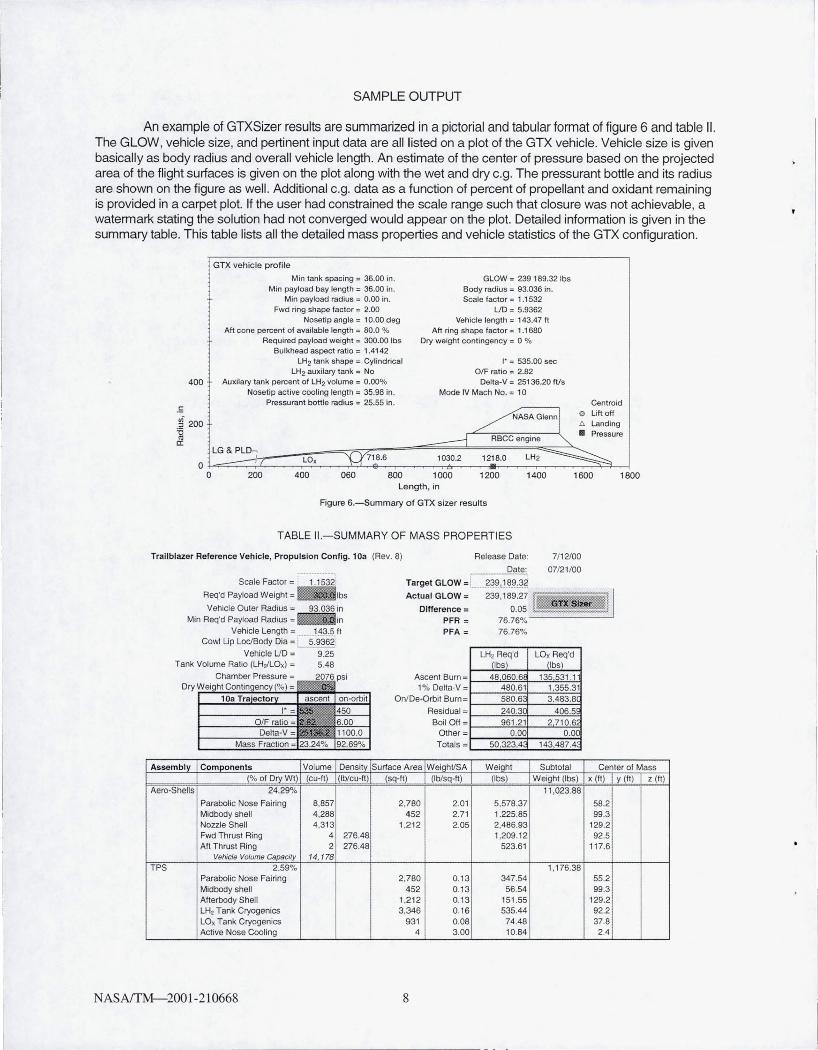
An example of GTXSizer results are summarized in a pictorial and tabular format of figure 6 and table II. The GLOW, vehicle size, and pertinent input data are all listed on a plot of the GTX vehicle. Vehicle size is given basically as body radius and overall vehicle length. An estimate of the center of pressure based on the projected area of the flight surfaces is given on the plot along with the wet and dry c.g. The pressurant bottle and its radius are shown on the figure as well. Additional c.g. data as a function of percent of propellant and oxidant remaining is provided in a carpet plot. If the user had constrained the scale range such that closure was not achievable, a watermark stating the solution had not converged would appear on the plot. Detailed information is given in the summary table. This table lists all the detailed mass properties and vehicle statistics of the GTX configuration.
400
. S
GTX vehicle prof ile
Min tank spacing; 36.00 in . Min payload bay length; 36.00 in .
Min payload radius; 0.00 in. Fwd ring shape factor; 2.00
Nosetip angle; 10.00 deg Aft cone percent of available length; 80.0 %
Required payload weight; 300.00 Ibs Bulkhead aspect ratio = 1.4142
LH2 tank shape; Cylindrical LH2 auxilary tank = No
Auxilary tank percent of LH2 volume; 0.00% Nosetip active COOling length = 35.98 in.
Pressurant bottle radius = 25.55 in .
GLOW = 239 189.32 Ibs Body radius = 93.036 in. Scale factor = 1.1532
UD= 5.9362 Vehicle length; 143.47 ft
Aft ring shape factor = 1.1680 Dry weigh1 contingency = a %
I' = 535.00 sec OIF ratio; 2.82
Delta-V; 25136.20 ftls Mode IV Mach No. = 10
Centroid
gf 200 '0
/NASA Glenn l e Lift off / I l!. Landing
• Pressure '" a: -----l RBCC engine """
LG& PLn~~ ____ --~-===~~~~====~~~~==~~==~~~~~~ ~:7 l Ox "Q'718.6 1 030.2 1218.0 lH2 ~ O ~~~~~~~~~~~~~~~~~~~~~~~~~~~~~~
o 200 400 060 800 1000 1200 1400 1600 Length, in
Figure 6.-Summary o f GTX sizer results
TABLE II.-SUMMARY OF MASS PROPERTIES
Trailblazer Reference Vehicle, Propu ls ion Config. 10a (Rev. 8)
Scale Factor =: 1.1532
Req'd Payload Weight = IIIIIlbS
Vehicle Outer Radius; 93.036 in
Release Date:
Date:
Target GLOW = ....?~~,1f.l.~.}?
Actual GLOW = 239,189.27
Difference = 0.05
7112100
07/21 /00
Min Req'd Payload Radius = ~in Vehicle Length = ....... ...1.:'P,!). It
Cowl Lip LociBody Dia =: 5.9362'
PFR = 76.76%--------'
Vehicle LID = 9.25 Tank Volume Ratio (LH,ILOx) = 5.48
PFA = 76.76%
Ascent Burn = 1% Delta-V =
OnlDe-Orbit Bum=
ResidualBoIIOf!
Other = Totals =
LH, Req'd ~lbsL 48060.6!!
480.61 580.6
240.3 961.21
0.00 50,323.4
LOx Req'd Jibs}
t 35531.11 1,355.31 3.483.El(
406.~
2710.6 o.oe
143,487.""
1800
Assembly Components Volume Density Surface Area WeighVSA Weight Subtotal Center 01 Mass (% of DryWt) (cu-It) (Ib/cu-ft) (sq-It) (Ib/sq-tt) (Ibs) Weighl (Ibs) x (tt) Y (It) z (t1)
Aero-Shells 24.29% 11 ,023.88
Parabolic Nose Fairing 8,857 2,780 2.01 5,578.37 58.2 Midbody shell 4.288 452 2.71 1,225.85 99.3 Nozzle Shell 4,313 1.212 2.05 2,486.93 129.2 Fwd Thrust Ring 4 276.48 1,209.12 92.5 Aft Thrust Ring 2 276.48 523.61 117.6
Vehicle Volume Gapacity 14, 178 TPS 2.59% 1.176.38
Parabolic Nose Fairing 2,780 0.13 347.54 55.2 Midbody shell 452 0.13 56.54 99.3 Afterbody Shell 1.212 0.13 151 .55 129.2 LH2 Tank Cryogenics 3,346 0.16 535.44 92.2 LOx Tank Cryogenics 931 0.08 74.48 37.8 Active Nose Cooling 4 3.00 10.84 2.4
NASAfTM- 2001-210668 8
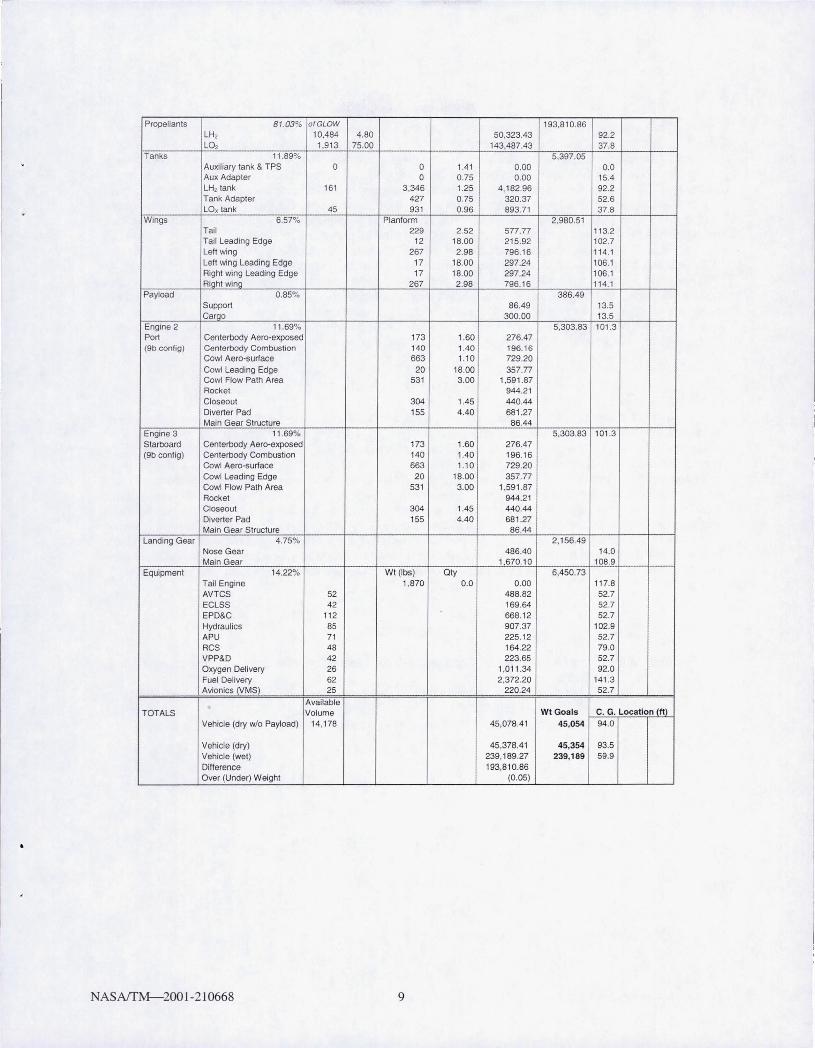
Propellants 81.03% a/GLOW 193,810.86 LH, 10.484 4.80 50.323.43 92.2 LO, 1,913 75.00 143,487.43 37.8
Tanks 11.89% 5,397.05 Auxi liary tank & TPS 0 0 1.41 0.00 0.0 Aux Adapter 0 0.75 0.00 15.4 LH, tank 161 3,346 1.25 4,182.96 92.2 Tank Adapter 427 0.75 320.37 52.6 LOx tank 45 931 0.96 893.71 37.8
Wings 6 .57~~ Planform 2,980.51 Tail 229 2.52 577.77 113.2 Tail Leading Edge 12 18.00 215.92 102.7 Left wing 267 2.98 796.16 114.1 Left wing Leading Edge 17 18.00 297.24 106.1 Right wing Leading Edge 17 18.00 297.24 106. 1 Right wing 267 2.98 796.16 114.1
Payload 0.85% 386.49 Support 86.49 13.5 Cargo 300.00 13.5
Engine 2 11.69% 5,303.83 101 .3 Port Centerbody Aero-exposed 173 1.60 276.47 (9b conti g) Centerbody Combustion 140 1.40 196.16
Cowl Aero-surface 663 1.10 729.20 Cowl Leading Edge 20 18.00 357.77 Cowl Flow Path Area 531 3.00 1,591.87 Rocket 944.21 Closeout 304 1.45 440.44 Diverter Pad 155 4.40 681.27 Main Gear Structure 86.44
Engine 3 11 .69% 5.303.83 101.3 Starboard Centerbody Aero-exposed 173 1.60 276.47 (9b conti g) Centerbody Combustion 140 1.40 196.1 6
Cowl Aero-surface 663 1.10 729.20 Cowl Leading Edge 20 18.00 357.77 Cowl Flow Path Area 531 3.00 1.591 .87 Rockel 944.21 Closeout 304 1.45 440.44 Diverter Pad 155 4.40 681 .27 Main Gear Structure 86.44
Landing Gear 4.75% 2,156.49 Nose Gear 486.40 14.0 Main Gear 1.670.10 108.9
Equipment 14.22% Wt(lbs) Qty 6,450.73 Tail Engine 1,870 0.0 0.00 117.8 AVTCS 52 488.82 52.7 ECLSS 42 169.64 52.7 EPD&C 112 668.12 52.7 Hydraulics 85 907.37 102.9 APU 71 225.12 52.7 RCS 48 164.22 79.0 VPP&D 42 223.65 52.7 Oxygen Delivery 26 1.011 .34 92.0 Fuel Delivery 62 2.372.20 141.3 Avionics (VMS) 25 220.24 52.7
Available TOTALS Volume WtGoals C. G. Location (It)
Vehicle (dry wlo Payload) 14,178 45,078.41 45,054 94.0
Vehicle (dry) 45,378.41 45,354 93.5 Vehicle (wet) 239,189.27 239,189 59.9 Difference 193,810.86 Over (Under) Weight (0.05)
N ASAffM-200 1-210668 9
VERIFICATION
The verification process for the preliminary sizing tool is an expensive interdisciplinary set of analyses. Initially a trajectory simulation is performed using OTIS. Required input for OTIS includes a matrix of the aerodynamic data, propulsion performance data, and vehicle mass properties. The basis of this data is the preliminary sizing established with GTXSizer. OTIS will establish a trimmed trajectory and accurately calculate propellant usage and 1*. These numbers are compared to the GTXSizer results and adjustments to the GTXSizer are made if necessary. Upon acceptable convergence a preliminary design exercise is initiated. Key sizing dimensions are built into a PRO-E solid model and the primary structure and subsystems are packaged. The solid model is transferred into PATRAN where it is used to generate both the thermal and structural models.
The environmental loading is established with APAS, MINIVER, and NASTRAN utilizing the trajectory data. Subsequently, a structural analysis is performed in NASTRAN. The results are post processed in both PATRAN and a specialized code called Hypersizer (ref. 3). Optimal areal weights are determined by Hypersizer, because it has the ability to compare all the loading events and determine the lowest margin of safety based on a broad spectrum of failure mode checks. In addition, multiple material systems including isotropic, laminates, and composites can be compared with one another to determine the minimum areal density of a given component. These new areal weights are then input to the GTXSizer and a new vehicle size is determined.
CONCLUDING REMARKS
The GTXSizer spreadsheet tool provides a means to quickly evaluate the size of a closed vehicle for a given set of performance parameters. Variations can be made in several geometric constraints, such as tank shape and cylinder plug length, in order to assess their impact on the GLOW. While the tool expedites the closure determination, several additions to the software can be made to account for more variables and improve the solution accuracy. For instance, further structural analysis can determine an optimum bulkhead aspect ratio for each of the fore and aft tank bulkheads based on the work in reference 2. Structural weight of the bulkheads can then be adjusted in the software when a nonoptimal aspect ratio is used. In addition, the GTXSizer can be modified to allow for different aspect ratios for each of the bulkheads. Finally, the GTXSizer can be modified to allow for multiple dry weight contingency factors for each component and assembly, instead of just one factor for the entire vehicle. That way if a certain component such as a wing box is designed and analyzed with greater precision than other parts of the structure, that can be reflected in a lower dry weight contingency factor for that component.
REFERENCES
1. Roskam, Jan: Airplane Design. Part 5-Component Weight Estimation. Roskam Aviation and Engineering Corp. , Ottawa, KS, 1989.
2. Chauncey, K.; and Lepsch, Roger A. , Jr. : Nontangent, Developed Contour Bulkheads for a Single-Stage Launch Vehicle. AIAA Paper 99-0835, 2000.
3. HyperSizer® Structural Sizing Software. Third ed. , Collier Research and Development Corporation, Hampton, VA, 1998.
N ASAITM-200 1-210668 10
REPORT DOCUMENTATION PAGE Form Approved
OMB No. 0704-0188
Public reporting burden for this collection of information is estimated to average 1 hour per response, including the time for reviewing instructions, searching existing data sources, gathering and maintaining the data needed. and completing and reviewing the coliection of information. Send comments regarding this burden estimate or any other aspect of this collection of information, including suggestions for reducing this burden, to Washington Headquarters Services. Directorate for Information Operations and Reports, 1215 Jefferson Davis Highway, Suite 1204, Arlington, VA 22202·4302, and to the Office of Management and Budget, Paperwork Reduction Project (0704·0188), Washington, DC 20503.
1. AGENCY USE ONLY (Leave blank) 12. REPORT DATE 1
3.
REPORT TYPE AND DATES COVERED
January 2001 TechrUcal ~en1orandum 4 . TITLE AND SUBTITLE 5 . FUNDING NUMBERS
Preliminary Sizing of Vertical Take-Off Rocket-Based Combined-Cycle Powered Launch Vehicles
6. AUTHOR(S) ~-708-73-20-00
Joseph M. Roche and David R. ~cCurdy
7. PERFORMING ORGANIZATION NAME(S) AND ADDRESS(ES) 8 . PERFORMING ORGANIZATION REPORT NUMBER
National Aeronautics and Space Administration John H. Glenn Research Center at Lewis Field E-12503-1 Cleveland, Ohio 44135-3191
9 . SPONSORINGIMONITORING AGENCY NAME(S) AND ADDRESS(ES) 10. SPONSORING/MONITORING AGENCY REPORT NUMBER
National Aeronautics and Space Administration Washington, DC 20546-0001 NASA T~-2001 -210668
11. SUPPLEMENTARY NOTES
Prepared for the 37th Combustion Subcommittee, 25th Airbreathing Propulsion Subcommittee, and 19th Propulsion Systems Hazards Subcommittee Joint ~eeting sponsored by the Joint Arrny-Navy-Air Force Interagency Propulsion Commirtee, Monterey, California, November 13-17, 2000. Joseph~. Roche, NASA Glenn Research Center; David R. McCurdy, Dynacs Engineering Company, Inc. , 2001 Aerospace Parkway, Brook Park, Ohio 44142. Responsible person, Joseph M. Roche, organization code 7740, 216-433-2575.
12a. DISTRIBUTION/AVAILABILITY STATEMENT 12b. DISTRIBUTION CODE
Unclassified -Unlimited Subject Category: 16 Distribution: Nonstandard
Available electronically at http://gltrs.grc.nasa. gov/GLTRS
This publication is available from the NASA Center for AeroSpace Infonnation, 301-621-0390. 13. ABSTRACT (Maximum 200 words)
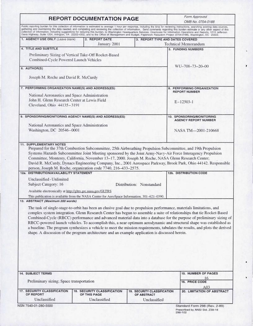
The task of single-stage-to-orbit has been an elusive goal due to propulsion performance, materials limitations, and complex system integration. Glenn Research Center has begun to assemble a suite of relationships that tie Rocket-Based Combined-Cycle (RBCC) performance and advanced material data into a database for the purpose of preliminary sizing of RBCC-powered launch vehicles. To accomplish this, a near optimum aerodynanuc and structural shape was established as a baseline. The program synthesizes a vehicle to meet the mission requirements, tabulates the results, and plots the derived shape. A discussion of the program architecture and an example application is discussed herein.
14. SUBJECT TERMS 15. NUMBER OF PAGES
16 Preliminary sizing; Space transportation 16. PRICE CODE
A03 17. SECURITY CLASSIFICATION 18. SECURITY CLASSIFICATION 19. SECURITY CLASSIFICATION 20. LIMITATION OF ABSTRACT
OF REPORT OFTHIS PAGE OF ABSTRACT
Unclassified Unclassified Unclassified
NSN 7540-01 -280-5500 Standard Form 298 (Rev. 2 -89) Prescribed by ANSI Std. Z39-1B 298-102