preliminary study on radio frequency neutralizer for ion engine
TRANSCRIPT
The 30th
International Electric Propulsion Conference, Florence, Italy
September 17-20, 2007
1
Preliminary Study on Radio Frequency Neutralizer for Ion
Engine
IEPC-2007-226
Presented at the 30th
International Electric Propulsion Conference, Florence, Italy
September 17-20, 2007
Tomoyuki Hatakeyama*, Masatoshi Irie
*, Hiroki Watanabe
*,
Aasami Okutsu*, Junichiro Aoyagi
†, and Haruki Takegahara
‡
Tokyo Metropolitan University, Hino, Tokyo, 191-0065, Japan
Abstract: The Radio Frequency (RF) cathode enables instantaneous ignition and
simple handling by the oxide-insert-free design. Moreover, it may even allow a longer life
compared with hollow cathode. In this investigation, the cathode with RF was fabricated and
tested for application especially for the neutralizer of the RF ion engine system. The RF
cathode achieved high performance, over 1700 mA at 80 W of RF input power and 3 sccm of
xenon gas. The performance was evaluated by gas utilization factor and electron extraction
cost. The successful results imply feasibility of the new RF ion thruster system; single
oscillator that generates both plasmas for the thruster and the neutralizer can simplify the
power supply system besides fully utilizing the characteristics of the RF discharge as
mentioned above.
Nomenclature
C = electron extraction cost
It = electron current extracted by the target
m = mass flow rate
PIn = radio frequency input power
U = gas utilization factor
Vt = target voltage
* Graduate Student, Dept. Aerospace Engineering, [email protected].
† Assistant Professor, Dept. Aerospace Engineering, [email protected].
‡ Professor, Dept. Aerospace Engineering, [email protected].

The 30th
International Electric Propulsion Conference, Florence, Italy
September 17-20, 2007
2
I. Introduction
ON thrusters require electron emission devices, generally using hollow cathodes for a discharge chamber and
a neutralizer. The hollow cathode provides high electron current density on relatively low electric power and gas
flow rate consumption. However, it is also well known that its lifetime is limited by depletion and degradation of an
oxide insert. Additionally, the insert must be avoid contact with active gas and also requires to be preheated for
several minutes before operation. As a result, propulsion systems with the hollow cathode are unable to be switched
on quickly and require careful handling.
RF ion thrusters have been developed and put to practical use as RIT series by Giessen University and ESA 1.
The RF ion thruster enables the hollow-cathode-free discharge for the plasma production. For the neutralization of
ion beam, however, the conventional RF ion thruster uses the hollow cathode which has an oxide insert.
We have been investigating and developing the radio frequency cathode for application especially for the
neutralizer of the RF ion engine system. The neutralizer with RF enables instantaneous ignition and simple handling
by the insert-free design, it may even allow a longer life. By realizing a practical RF neutralizer, single oscillator
that generates both plasmas for the thruster and the neutralizer can simplify the power supply system besides
sufficient utilization the characteristics of the RF discharge as mentioned above.
II. Experimental Apparatus and Procedure
The RF cathode designed for this investigation is shown
in Figs. 1 and 2. The plasma chamber for discharge is made
of Pyrex, and the mica plate covered the downstream exit of
the chamber. The plate provides an axial boundary for the
plasma containment and increasing inner gas pressure. There
was 2 mm diameter orifice in the center of the mica plate. In
the chamber, the ion collector was set to trap ions from the
plasma.
The anode target was located about 50 mm downstream of
the orifice plate. (See Fig. 3) The target was biased positively
by the DC power supply. The potential difference between
the grounded ion collector and the target simulates that
between the beam plasma and the neutralizer common in the
practical operation.
For the cathode operation, the neutral xenon gas was fed
into the discharge chamber via the mass flow controller. The
RF coil was connected to the RF source (13.56 MHz) through
the matching network, which reduces reflected power to
maximize input power to a load. The RF power creates RF
electric field in the circumferential direction inside of the coil. The xenon gas is coupled by this electric field, and then the plasma is produced. The experimental parameters were set as follows; xenon
gas flow rate of 0.3, 0.5, 1.0, 2.0, 3.0 sccm and RF input
power of 10, 20, 40, 80 W. The target voltage was varied from
0 to 80 V, and the electron current extracted by the target was
measured. All experiments were conducted in the vacuum
chamber which has 1.6 m diameter and 3.2 m long. The
pumping system which is mounted the chamber maintained
pressure under 10-4
Pa.
I
Figure 1. Schematic illustration of RF cathode.
Figure 2. Side view of RF cathode and target.
RF Coil
Mica Plate
Ion Collector
Xenon Gas
Discharge Chamber
Orifice

The 30th
International Electric Propulsion Conference, Florence, Italy
September 17-20, 2007
3
III. Results and Discussions
A. I-V characteristics
Figure 4 shows current-voltage characteristics of the RF cathode at 80 W of RF input power. The small and
approximately constant current was measured at the low target voltage. As the target voltage was raised, the sharp
rise of extracted current and the plume near the orifice was observed as shown in Figs. 4 and 5. In higher flow rate
operation, this transition of extraction mode was more obvious, and the mode transition occurred at lower voltage.
The mode transition occurred by the reason that the difference between the plasma potential in the chamber and
the ion collector potential creates the ion sheath at surface on the ion collector. The created sheath increased ion
current extracted from the plasma in the chamber dramatically. In consequence, electron current extracted from
the orifice was also increased. At 2 and 3 sccm operation, the current peaked at the low target voltage.
Figure 3. Schematic illustration of RF cathode and experimental system.
Figure 5. Mode transition of RF cathode.
Figure 4. Current-voltage characteristics of RF cathode
at 80 W of RF input power.
RF Cathode
Matching Network
Target
Xenon Gas
Vacuum Chamber
RF Generator
Mass Flow Controller
Camera
50mm DC Power Supply
Observation Window
Target Voltage, Vt, V Extr
acte
d E
lectr
on
Cu
rre
nt,
It , m
A
Pin = 80 W, m = 2 sccm
Pin = 80 W, m = 2 sccm
Vt = 20 V, It = 90 mA
Vt = 40V, It =1520 mA
Ta
rge
t T
arg
et
The 30th
International Electric Propulsion Conference, Florence, Italy
September 17-20, 2007
4
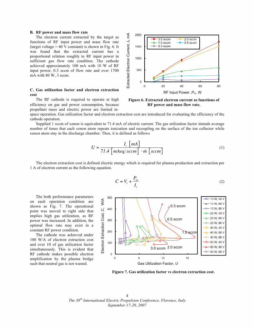
B. RF power and mass flow rate
The electron current extracted by the target as
functions of RF input power and mass flow rate
(target voltage = 40 V constant) is shown in Fig. 6. It
was found that the extracted current has a
proportional relation roughly to RF input power in
sufficient gas flow rate condition. The cathode
achieved approximately 100 mA with 10 W of RF
input power, 0.3 sccm of flow rate and over 1700
mA with 80 W, 3 sccm.
C. Gas utilization factor and electron extraction
cost
The RF cathode is required to operate at high
efficiency on gas and power consumption, because
propellant mass and electric power are limited in-
space operation. Gas utilization factor and electron extraction cost are introduced for evaluating the efficiency of the
cathode operation.
Supplied 1 sccm of xenon is equivalent to 71.4 mA of electric current. The gas utilization factor intends average
number of times that each xenon atom repeats ionization and recoupling on the surface of the ion collector while
xenon atom stay in the discharge chamber. Thus, it is defined as follows
U =It mA[ ]
71.4 mAeq sccm[ ] �m sccm[ ] (1)
The electron extraction cost is defined electric energy which is required for plasma production and extraction per
1 A of electron current as the following equation.
C = Vt +PinIt
(2)
The both performance parameters
on each operation condition are
shown as Fig. 7. The operational
point was moved to right side that
implies high gas utilization, as RF
power was increased. In addition, the
optimal flow rate may exist in a
constant RF power condition.
The cathode was achieved under
100 W/A of electron extraction cost
and over 10 of gas utilization factor
simultaneously. This is evident that
RF cathode makes possible electron
amplification by the plasma bridge
such that neutral gas is not wasted.
Figure 6. Extracted electron current as functions of
RF power and mass flow rate.
Figure 7. Gas utilization factor vs electron extraction cost.
Extr
acte
d E
lectr
on
Cu
rre
nt,
It, m
A
RF Input Power, Pin, W
Gas Utilization Factor, U
Ele
ctr
on
Extr
actio
n C
ost,
C, W
/A
0.3 sccm
0.5 sccm
1.0 sccm
2.0 sccm 3.0 sccm
The 30th
International Electric Propulsion Conference, Florence, Italy
September 17-20, 2007
5
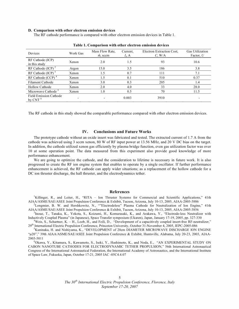
D. Comparison with other electron emission devices
The RF cathode performance is compared with other electron emission devices in Table 1.
The RF cathode in this study showed the comparable performance compared with other electron emission devices.
IV. Conclusions and Future Works
The prototype cathode without an oxide insert was fabricated and tested. The extracted current of 1.7 A from the
cathode was achieved using 3 sccm xenon, 80 W of RF input power at 13.56 MHz, and 20 V DC bias on the target.
In addition, the cathode utilized xenon gas efficiently by plasma bridge function, even gas utilization factor was over
10 at some operation point. The data measured from this experiment also provide good knowledge of more
performance enhancement.
We are going to optimize the cathode, and the consideration to lifetime is necessary in future work. It is also
progressed to create the RF ion engine system that enables to operate by a single oscillator. If further performance
enhancement is achieved, the RF cathode can apply wider situations; as a replacement of the hollow cathode for a
DC ion thruster discharge, the hall thruster, and the electrodynamics tether.
References 1Killinger, R., and Leiter, H., “RITA – Ion Thruster Systems for Commercial and Scientific Applications,” 41th
AIAA/ASME/SAE/ASEE Joint Propulsion Conference & Exhibit, Tucson, Arizona, July 10-13, 2005, AIAA-2005-3886
2Longmier, B. W. and Hershkowitz, N., “”Electrodeless” Plasma Cathode for Neutralization of Ion Engine,” 41th
AIAA/ASME/SAE/ASEE Joint Propulsion Conference & Exhibit, Tucson, Arizona, July 10-13, 2005, AIAA-2005-3856
3Inoue, T., Tanaka, K., Yokota, S., Koizumi, H., Komurasaki, K., and Arakawa, Y., “Electrode-less Neutralizer with
Inductively Coupled Plasma” (in Japanese), Space Transfer symposium (Ukaren), Japan, January 17-19, 2005, pp. 327-330 4Weis, S., Schartner, K. – H., Loeb, H., and Feili, D., “Development of a capacitively coupled insert-free RF-neutralizer,”
29th
International Electric Propulsion Conference, Princeton University, October 31-November 4, 2005, IEPC-2005-086 5Kuninaka, H. and Nishiyama, K., “DEVELOPMENT of 20cm DIAMETER MICROWAVE DISCHARGE ION ENGINE
“μ20”,” 39th AIAA/ASME/SAE/ASEE Joint Propulsion Conference & Exhibit, Huntsville, Alabama, July 20-23, 2003, AIAA-
2003-5011 6Okawa, Y., Kitamura, S., Kawamoto, S., Iseki, Y., Hashimoto, K., and Noda, E., “AN EXPERIMENTAL STUDY ON
CABON NANOTUBE CATHODES FOR ELECTRODYNAMIC TETHER PROPULSION,” 56th International Astronautical
Congress of the International Astronautical Federation, the International Academy of Astronautics, and the International Institute
of Space Law, Fukuoka, Japan, October 17-21, 2005 IAC -05C4.4.07
Table 1. Comparison with other electron emission devices
Devices Work Gas Mass Flow Rate,
m, sccm
Current,
It, A
Electron Extraction Cost,
C, W/A
Gas Utilization
Factor, U
RF Cathode (ICP)
in this study Xenon 2.0 1.5 93 10.6
RF Cathode (ICP) 2 Argon 15.0 3.5 186 3.8
RF Cathode (ICP) 3 Xenon 1.5 0.7 111 7.1
RF Cathode (CCP) 4 Xenon 1.5 0.1 510 0.37
Filament Cathode Xenon 3.0 0.3 205 1.4
Hollow Cathode Xenon 2.0 4.0 33 28.0
Microwave Cathode 5 Xenon 1.0 0.5 70 11.5
Field Emission Cathode
by CNT 6
- - 0.003 3910 -