premium sound upgrade for audi tt2 (2007 - alpine · premium sound upgrade for audi tt2 (2007...
TRANSCRIPT

PREMIUM SOUND UPGRADE FOR AUDI TT2 (2007 - >)
SPC-400TT
Installation Manual

Contents
1 Notes and safety instructions . . . . . . . . . . . . . . . . . . . . . . . . . . . . . . . . . . . . . . . . . . . . . . . . . . . . . . . . . . . . . . . . . . . . . . . . . . . 11.1 General notes . . . . . . . . . . . . . . . . . . . . . . . . . . . . . . . . . . . . . . . . . . . . . . . . . . . . . . . . . . . . . . . . . . . . . . . . . . . . . . . . . . . . . . . . . . . . . . . 11.2 General safety instructions for pyrotechnical, electrical and mechanical components of the re-
straint system . . . . . . . . . . . . . . . . . . . . . . . . . . . . . . . . . . . . . . . . . . . . . . . . . . . . . . . . . . . . . . . . . . . . . . . . . . . . . . . . . . . . . . . . . . . . . . . . 12 Parts overview . . . . . . . . . . . . . . . . . . . . . . . . . . . . . . . . . . . . . . . . . . . . . . . . . . . . . . . . . . . . . . . . . . . . . . . . . . . . . . . . . . . . . . . . . . . . . 33 Assembly overview . . . . . . . . . . . . . . . . . . . . . . . . . . . . . . . . . . . . . . . . . . . . . . . . . . . . . . . . . . . . . . . . . . . . . . . . . . . . . . . . . . . . . . . . 43.1 Coupé (for all radio variants, as well as right-hand and left-hand drives) . . . . . . . . . . . . . . . . . . . . . . . . . . . . . . . 43.2 Roadster (for all radio variants, as well as right-hand and left-hand drives) . . . . . . . . . . . . . . . . . . . . . . . . . . . . 64 Preparations . . . . . . . . . . . . . . . . . . . . . . . . . . . . . . . . . . . . . . . . . . . . . . . . . . . . . . . . . . . . . . . . . . . . . . . . . . . . . . . . . . . . . . . . . . . . . . . . 85 Installing the “Alpine SPC-400TT” installation kit . . . . . . . . . . . . . . . . . . . . . . . . . . . . . . . . . . . . . . . . . . . . . . . . . . . . . . 95.1 Installing the radio wiring harness . . . . . . . . . . . . . . . . . . . . . . . . . . . . . . . . . . . . . . . . . . . . . . . . . . . . . . . . . . . . . . . . . . . . . . . . . 95.2 Installing the “Alpine SPC-400TT” amplifier . . . . . . . . . . . . . . . . . . . . . . . . . . . . . . . . . . . . . . . . . . . . . . . . . . . . . . . . . . . . . . . . . 155.3 Replacing the front left and right tweeters (all vehicles) . . . . . . . . . . . . . . . . . . . . . . . . . . . . . . . . . . . . . . . . . . . . . . . . . 205.4 Installing the front left and right bass loudspeakers (all vehicles) . . . . . . . . . . . . . . . . . . . . . . . . . . . . . . . . . . . . . . . 205.5 Connecting the front left and right mid-range loudspeakers (all vehicles) . . . . . . . . . . . . . . . . . . . . . . . . . . . . . . 215.6 Attaching the debounce kit to the door, right and left (all vehicles) . . . . . . . . . . . . . . . . . . . . . . . . . . . . . . . . . . . . . . 225.7 Assembling the vehicle . . . . . . . . . . . . . . . . . . . . . . . . . . . . . . . . . . . . . . . . . . . . . . . . . . . . . . . . . . . . . . . . . . . . . . . . . . . . . . . . . . . . . 225.8 Returning the vehicle . . . . . . . . . . . . . . . . . . . . . . . . . . . . . . . . . . . . . . . . . . . . . . . . . . . . . . . . . . . . . . . . . . . . . . . . . . . . . . . . . . . . . . . 22
.

1 Notes and safety instructions
1.1 General notesPlease read and take note of these WARNING, Caution andNote descriptions before carrying out maintenance or repairwork.
Caution
Text with this symbol indicates the risk of damage to yourvehicle.
Note
Text with this symbol contains additional information.
The pages that follow contain all of the information (subjectto technical changes) required to retrofit the “Alpine SPC-400TT"system. This description corresponds to the status ofthe Workshop Manual at the time of going to press.
The “Alpine SPC-400TT” system must be installed by aqualified workshop. Special tools, testing devices and vehi-cle-specific literature will be needed to perform the installa-tion. Improper installation can cause damage to the vehicleor the “Alpine SPC-400TT” system.
Alpine will not accept responsibility in the event of failure to comply with these installation instructions.
1.2 General safety instructions for pyro-technical, electrical and mechanicalcomponents of the restraint system
Pyrotechnical components comprise:
Airbag units
Belt tensioners
Seatbelt load limiter (depending on fixtures)
Battery disconnecting elements (depending on fixtures)
In general:
Testing, installation and maintenance tasks must only becarried out by trained personnel.
Do not check using circuit tester, voltmeter, or ohmmeter un-der any circumstances.
1

Before handling pyrotechnical components of the restraintsystem (e.g. before disconnecting the electrical connector),the person carrying out the task must “discharge any staticelectricity”. This can be done by briefly touching the doorlatch, for example.
The power supply to the system must always be disconnec-ted when working on the pyrotechnical components of therestraint system.
Disconnect the battery when the ignition is switched offThe battery negative terminal must subsequently be covered.
No waiting time is necessary after the battery has been dis-connected.
Observe the measures that apply after disconnecting thebattery
Pyrotechnical components must neither be opened nor re-paired. Strictly use new parts only.
Pyrotechnic components that have fallen onto a hard surfaceor that show any sign of damage must not be installed.
Pyrotechnical components of the restraint system must beinstalled immediately after they have been taken out of thetransport container.
If work is put on hold, place the pyrotechnic componentsback into the transport container.
It is not permissible to leave pyrotechnical components ofthe restraint system sitting unsupervised.
“Wash hands” after touching ignited pyrotechnical compo-nents of the restraint system.
When connecting pyrotechnical components of the restraintsystem, only the person performing the work may be presentinside the vehicle.
Storage and transportation are subject to the applicable na-tional laws.
Pyrotechnical components must not be treated with grease,cleaners, or similar agents.
In addition, pyrotechnical components must not be exposedto temperatures above 100 °C, even on a temporary basis.
2

2 Parts overviewInstallation package SPC-400TT for the "chorus", “concert, symphony” radio systemsor with navigation system:
Parts list
SPC-400TT — Amplifier
Wiring harness TT2
Subwoofer — loudspeaker incl. seal, small partsand assembly partsSPC-400TT basic package
Debounce kit TT complete with installation instructionsTweeter -— loudspeaker with TT adapter ring
Mid-range — loudspeaker with TTadapter ring
Small parts and assembly parts
Installation instructions in English language
Additional component included:
Parts list
Wire adapter, applicable only for Audi TT2 modelsbuild year 2007–2009, which have a connector installed
Bracket for amplifier
3

3 Assembly overview
3.1 Coupé (for all radio variants, as well as right-hand and left-hand drives)
2 Treble loudspeaker,front rightq replace
3front rightq In the doors, bottomq is connected to the
standard wiring har-ness
q replace
4range and bass loud-speakerq connect
5q in right door, topq is also connected to
the bass loudspeak-er
q re-install
6control unit for thenavigation systemoperating electronicsq “concert, symphony” radio unit or with navigation systemq “chorus” radio unitq connect to the wiring harness in the installation kit
7 , rear right/left“concert, symphony” radio system or with navigation system:q No assembly work required for the loudspeaker
8 Tweeter, rear right/leftq No assembly work required for the loudspeaker
9q Positive wire from wiring harness in the installation kit to the standard fuse holder in the luggage com-
partmentq From the installation kit
4
Bass loudspeaker
1 N/A
Connection wire, mid-
Mid-range loudspeaker
Head unit: radio or
Mid-range loudspeaker
Positive wire (for "chorus" radio)

q Routeq Connection to standard fuse holderq secure with cable ties
10 Power supply connection wire (for “chorus” radio)q connect to battery
11 Vehicle electrics standard fuse holder (for “chorus” radio)q Positive wire from the Audi Sound Plus package is looped through hereq Route
12 Battery (for “chorus” radio)q connect via connection from fuse holder
13 Earth point (for “chorus” radio)q connect earth wire from the installation kit wiring harness to the earth point
14 “SPC-400TT” amplifierq Installationq connect to the wiring harness in the installation kit
15 Wiring harness from the installation kit “concert, symphony” or with navigation systemq is connected to the amplifierq is connected to the standard wiring harness
16 N/A
17 Wiring harness (for “chorus” radio)is routed only for “chorus” radio systemq Routeq secure with cable ties
18 Mid-range loudspeaker, front leftq in left door, topq is connected to the bass loudspeakerq re-install
19 Bass loudspeaker, front leftq in door, bottomq is connected to the standard and supplied wiring harnessq replaceq attach logo plate to the loudspeaker trim
20 Treble loudspeaker, front leftq replace
21 Centre mid-range and treble loudspeaker centre (for “concert, symphony” radio or with naviga-tion system)q No assembly work required for the loudspeaker
5

3.2 Roadster (for all radio variants, as well as right-hand and left-handdrives)
1 N/A
2 Treble loudspeaker,front rightq replace
3 Bass loudspeaker,front rightq In the doors, bottomq is connected to the
standard wiring har-ness
q replaceq attach logo plate to
the loudspeaker trim4 Connection wire, mid-
range and bass loud-speakerq connect
5 Mid-range loudspeak-erq in right door, topq is also connected to
the bass loudspeak-er
q re-install
6 Head unit: radio orcontrol unit for thenavigation systemoperating electronicsq “concert, symphony” radio unit or with navigation systemq “chorus” radio unitq connect to the wiring harness in the installation kit
7 Mid-range loud speaker, rear right/left“concert, symphony” radio system or with navigation system:q No assembly work required for the loudspeaker
8 Positive wire (for “chorus” radio)q Positive wire from wiring harness from the installation kit to the fuse holderq From the installation kitq Routeq connect to fuse holderq secure with cable ties
9 Power supply connection wire (for “chorus” radio)q route to battery
6

10 Vehicle electrics standard fuse holder (for “chorus” radio)q Positive wire from the Audi Sound Plus package is looped through hereq Route
11 Battery (for “chorus” radio)q connect via connection from fuse holder
12 Earth point (for “chorus” radio)q connect earth wire from the installation kit wiring harness to the earth point
13 “SPC-400TT” amplifierq Installationq connect to the wiring harness in the installation kit
14 Wiring harness from the installation kit “concert, symphony” or with navigation systemq is connected to the amplifierq is connected to the standard wiring harness
15 N/A
16 Wiring harness for Audi Sound plus (for “chorus” radio)q Routeq secure with cable ties
17 Mid-range loudspeaker, front leftq in left door, topq is also connected to the bass loudspeakerq re-install
18 Bass loudspeaker, front leftq in door, bottomq replaceq is connected to the standard and supplied wiring harnessq attach logo plate to loudspeaker trim
19 Treble loudspeaker, front leftq replace
20 Centre mid-range and treble loudspeaker centre (for “concert, symphony” radio or with naviga-tion system)q No assembly work required for the loudspeaker
7
4 PreparationsRemove for all vehicles:– Remove ignition key.
– Disconnect the battery
– Remove and install the door trim
– Remove and install the luggage compartment floor mat
– Remove and install the rear cross panel trim
Remove for the “concert, symphony” radio, or with naviga-tion system:– Remove and install the left-hand side luggage compartment
side trim
Remove for the “chorus” radio:– Remove and install Radio -R-
– Remove and install the instrument cluster
– Remove and install the driver-side dash panel cover
– Remove and install the bottom A-pillar trim
– Remove and install the sill panel trim
– Remove and install the bench seat (Coupé)
– Remove and install the side rear panel trim (Roadster)
– Remove and install the left-hand and right-hand luggagecompartment side trims
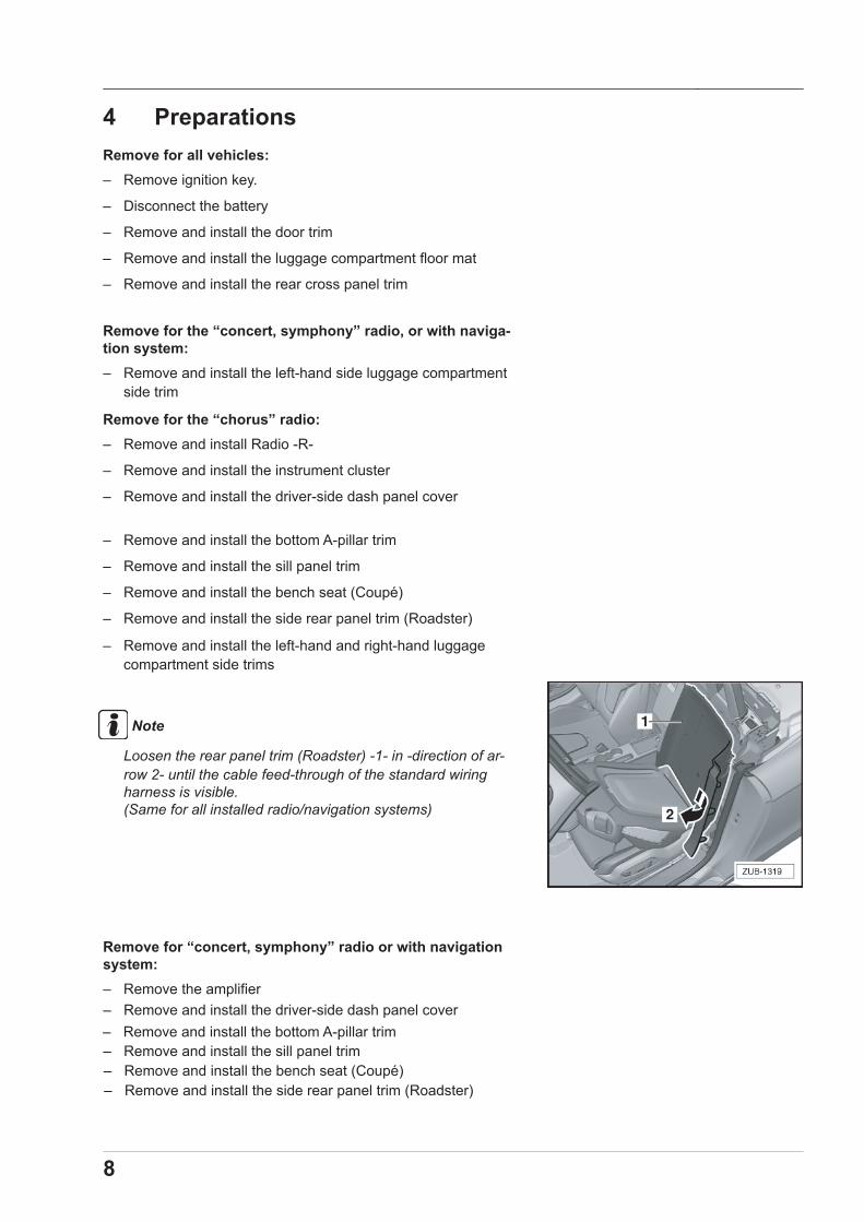
Note
Loosen the rear panel trim (Roadster) -1- in -direction of ar-row 2- until the cable feed-through of the standard wiringharness is visible.(Same for all installed radio/navigation systems)
Remove for “concert, symphony” radio or with navigationsystem:– Remove the amplifier
8
– Remove and install the driver-side dash panel cover – Remove and install the bottom A-pillar trim – Remove and install the sill panel trim – Remove and install the bench seat (Coupé) – Remove and install the side rear panel trim (Roadster)
5 Installing the “Alpine SPC-400TT”installation kit
5.1 Installing the radio wiring harnessInstalling the “chorus” radio wiring harness (Coupé) -> 5.1.1
Installing the “chorus” radio wiring harness (Roadster) -> 5.1.2
Installing the “concert, symphony” radio wiring harnessor with navigation system (all vehicles) -> 5.1.5
5.1.1 Installing the “chorus” radio wiring har-ness (Coupé)
Caution
Risk of damage to the wiring harness:Do not secure the wiring harness with cable ties until allconnections have been made.
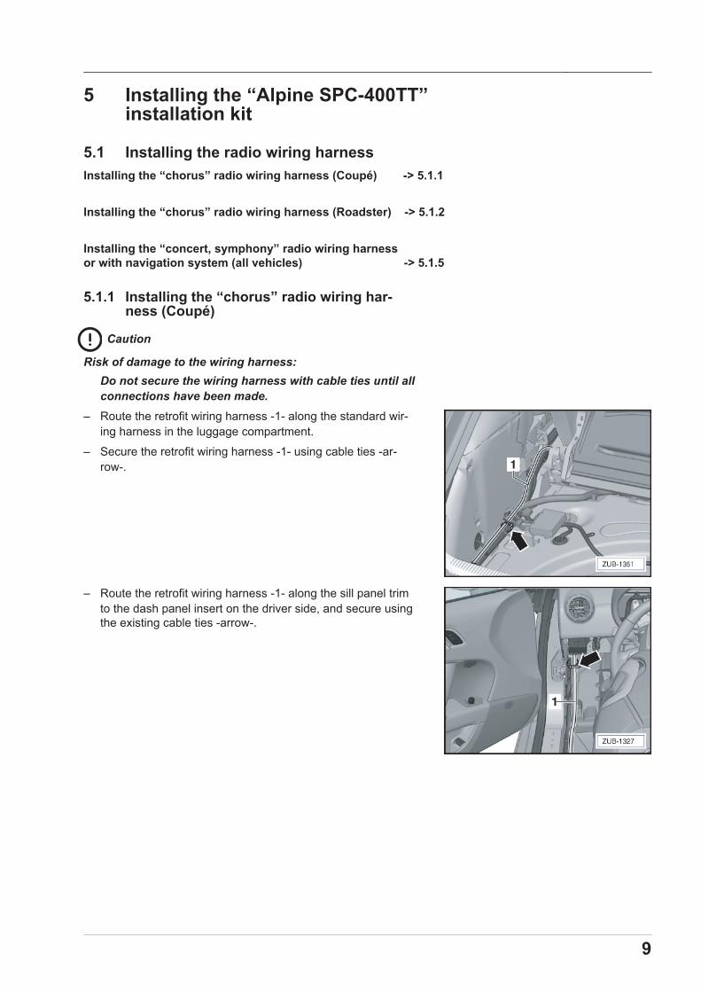
– Route the retrofit wiring harness -1- along the standard wir-ing harness in the luggage compartment.
– Secure the retrofit wiring harness -1- using cable ties -ar-row-.
– Route the retrofit wiring harness -1- along the sill panel trimto the dash panel insert on the driver side, and secure usingthe existing cable ties -arrow-.
9
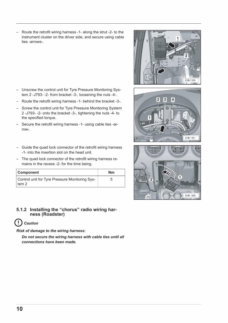
– Route the retrofit wiring harness -1- along the strut -2- to theinstrument cluster on the driver side, and secure using cableties -arrows-.
– Unscrew the control unit for Tyre Pressure Monitoring Sys-tem 2 -J793- -2- from bracket -3-, loosening the nuts -4-.
– Route the retrofit wiring harness -1- behind the bracket -3-.
– Screw the control unit for Tyre Pressure Monitoring System2 -J793- -2- onto the bracket -3-, tightening the nuts -4- tothe specified torque.
– Secure the retrofit wiring harness -1- using cable ties -ar-row-.
– Guide the quad lock connector of the retrofit wiring harness-1- into the insertion slot on the head unit.
– The quad lock connector of the retrofit wiring harness re-mains in the recess -2- for the time being.
Component Nm
Control unit for Tyre Pressure Monitoring Sys-tem 2
5
5.1.2 Installing the “chorus” radio wiring har-ness (Roadster)
Caution
Risk of damage to the wiring harness:Do not secure the wiring harness with cable ties until allconnections have been made.
10

– Pull the plug -2- for the retrofit wiring harness -1- through thecable feed-through of the rear panel -arrow- using a suitablegripping tool.
– Route the retrofit wiring harness -1- along the standard wir-ing harness in the luggage compartment.
– Secure the retrofit wiring harness -1- using the existing cableties -arrows-.
– Route the retrofit wiring harness -1- along the sill panel trimto the dash panel insert on the driver side and secure usingcable ties -arrow-.
– Route the retrofit wiring harness -1- along the strut -2- to theinstrument cluster on the driver side, and secure using cableties -arrows-.
11
– Unscrew the control unit for Tyre Pressure Monitoring Sys-tem 2 -J793- -2- from bracket -3-, loosening the nuts -4-.
– Route the retrofit wiring harness -1- behind the bracket -3-.
– Screw the control unit for Tyre Pressure Monitoring System2 -J793- -2- onto the bracket -3-, tightening the nuts -4- tothe specified torque.
– Secure the retrofit wiring harness -1- using cable ties -ar-row-.
– Guide the quad lock connector of the retrofit wiring harness-1- into the insertion slot on the head unit.
– The quad lock connector of the retrofit wiring harness re-mains in the recess -2- for the time being.
Component Nm
Control unit for Tyre Pressure Monitoring Sys-tem 2
5
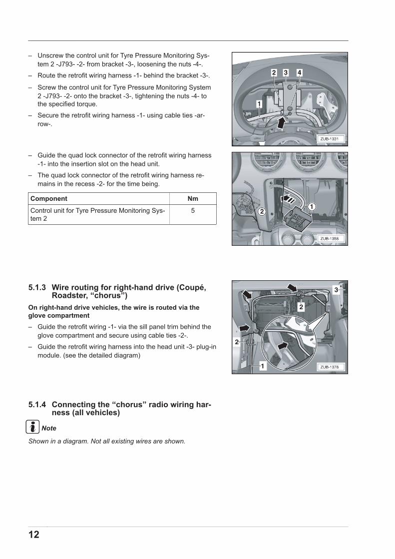
5.1.3 Wire routing for right-hand drive (Coupé,Roadster, “chorus”)
On right-hand drive vehicles, the wire is routed via theglove compartment– Guide the retrofit wiring -1- via the sill panel trim behind the
glove compartment and secure using cable ties -2-.
– Guide the retrofit wiring harness into the head unit -3- plug-inmodule. (see the detailed diagram)
5.1.4 Connecting the “chorus” radio wiring har-ness (all vehicles)
Note
Shown in a diagram. Not all existing wires are shown.
12
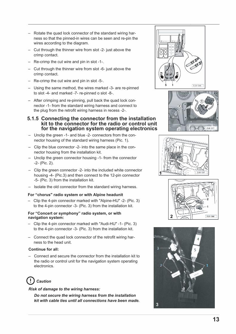
– Rotate the quad lock connector of the standard wiring har-ness so that the pinned-in wires can be seen and re-pin thewires according to the diagram.
– Cut through the thinner wire from slot -2- just above thecrimp contact.
– Re-crimp the cut wire and pin in slot -1-.
– Cut through the thinner wire from slot -6- just above thecrimp contact.
– Re-crimp the cut wire and pin in slot -5-.
– Using the same method, the wires marked -3- are re-pinnedto slot -4- and marked -7- re-pinned o slot -8-.
– After crimping and re-pinning, pull back the quad lock con-nector -1- from the standard wiring harness and connect tothe plug from the retrofit wiring harness in recess -2-.
– Connect the quad lock connector of the retrofit wiring har-ness to the head unit.
13
– Unclip the green -1- and blue -2- connectors from the con-nector housing of the standard wiring harness (Pic. 1).
– Clip the blue connector -2- into the same place in the con-nector housing from the installation kit.
– Unclip the green connector housing -1- from the connector-2- (Pic. 2).
– Clip the green connector -2- into the included white connectorhousing -4- (Pic.3) and then connect to the 12-pin connector -5- (Pic. 3) from the installation kit.
– Isolate the old connector from the standard wiring harness.
– Clip the 4-pin connector marked with "Alpine-HU" -2- (Pic. 3)to the 4-pin connector -3- (Pic. 3) from the installation kit.
navigation system:
For “chorus" radio system or with Alpine headunit
– Clip the 4-pin connector marked with "Audi-HU" -1- (Pic. 3)to the 4-pin connector -3- (Pic. 3) from the installation kit.
For “Concert or symphony” radio system, or with 2
1
Continue for all:– Connect and secure the connector from the installation kit to
the radio or control unit for the navigation system operatingelectronics.
Caution
Risk of damage to the wiring harness:Do not secure the wiring harness from the installationkit with cable ties until all connections have been made.
3
5.1.5 Connecting the connector from the installationkit to the connector for the radio or control unitfor the navigation system operating electronics

– The connector from the retrofit wiring harness must be re-pinned according to the following diagram.
– Cut through the thinner wire from slot -16- just above thecrimp contact.
– Re-crimp the cut wire and pin in slot -21-.
– Cut through the thinner wire from slot -17- just above thecrimp contact.
– Re-crimp the cut wire and pin in slot -18-.
– Cut through the thinner wire from slot -4- just above thecrimp contact.
– Re-crimp the cut wire and pin in slot -9-.
– Cut through the thinner wire from slot -5- just above thecrimp contact.
– Re-crimp the cut wire and pin in slot -6-.
Pinning the 32-pin connector
Note
32-pin wire adapter, applicable only for Audi TT2 models buildyear 2007–2009, which have a loudspeaker with 32-pin connec-tor installed.
– With the 32-pin connector from the retrofit wiring harness,the wires must be re-pinned according to the following dia-gram.
– Cut through the thinner wire from slot -3- just above thecrimp contact.
– Re-crimp the cut wire and pin in slot -8-.
– Cut through the thinner wire from slot -4- just above thecrimp contact.
– Re-crimp the cut wire and pin in slot -9-.
– Cut through the thinner wire from slot -15- just above thecrimp contact.
– Re-crimp the cut wire and pin in slot -10-.
– Cut through the thinner wire from slot -16- just above thecrimp contact.
– Re-crimp the cut wire and pin in slot -22-.
14
5.1.6 Connecting “concert, symphony” radiowiring harness or with navigation system(all vehicles)
The wiring harness adapter– is connected directly to the amplifier and to the “concert,
symphony” standard wiring harness or to the navigation sys-tem
Pinning the 38-pin connector
Note
Shown in a diagram. Not all existing wires are shown.
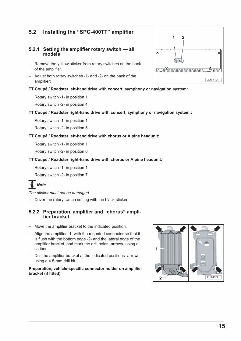
5.2 Installing the “SPC-400TT” amplifier
5.2.1 Setting the amplifier rotary switch — allmodels
– Remove the yellow sticker from rotary switches on the backof the amplifier.
– Adjust both rotary switches -1- and -2- on the back of theamplifier:
TT Coupé / Roadster left-hand drive with concert, symphony or navigation system:
Rotary switch -1- in position 1
Rotary switch -2- in position 4
TT Coupé / Roadster right-hand drive with concert, symphony or navigation system::
Rotary switch -1- in position 1
Rotary switch -2- in position 5
TT Coupé / Roadster left-hand drive with chorus or Alpine headunit:
Rotary switch -1- in position 1
Rotary switch -2- in position 6
TT Coupé / Roadster right-hand drive with chorus or Alpine headunit:
Rotary switch -1- in position 1
Rotary switch -2- in position 7
Note
The sticker must not be damaged.
– Cover the rotary switch setting with the black sticker.
5.2.2 Preparation, amplifier and “chorus” ampli-fier bracket
– Move the amplifier bracket to the indicated position.
– Align the amplifier -1- with the mounted connector so that itis flush with the bottom edge -2- and the lateral edge of theamplifier bracket, and mark the drill holes -arrows- using ascriber.
– Drill the amplifier bracket at the indicated positions -arrows-using a 4.5-mm drill bit.
Preparation, vehicle-specific connector holder on amplifierbracket (if fitted)
15

– Loosen the nuts on the vehicle-specific connector holder -3--arrows-.
– Move the amplifier bracket to the indicated position.
– Align the vehicle-specific connector holder -3- with the inneredge of the inner seam, and mark the drill holes -arrows- us-ing a scriber.
– Drill the vehicle-specific connector holder -3- at the pointsshown -arrows- using a 4.5-mm drill bit.
5.2.3 Preparation, amplifier on amplifier bracket“concert, symphony or with navigationsystem”
– Move the amplifier bracket to the indicated position.
– Align the amplifier -1- with the mounted connector so that itis flush with the bottom edge -2- and the lateral edge of theamplifier bracket, and mark the drill holes -arrows- using ascriber.
– Drill the amplifier bracket at the indicated positions -arrows-using a 4.5-mm drill bit.
Preparation, vehicle-specific connector holder on amplifierbracket (if fitted)
– Loosen the nuts on the vehicle-specific connector holder -3--arrows-.
16

– Move the amplifier bracket to the indicated position.
– Align the vehicle-specific connector holder -3- with the inneredge of the inner seam, and mark the drill holes -arrows- us-ing a scriber.
– Drill the vehicle-specific connector holder -3- at the pointsshown -arrows- using a 4.5-mm drill bit.
5.2.4 Installation, amplifier and vehicle-specificconnector holder (equipment variant)
“chorus” radio– Position the amplifier -5- with mounted connector-2-.
– Position the vehicle-specific connector holder -3- (if fitted) onthe rear of the amplifier bracket -4- and screw using nuts tothe specified torque.
– Position the amplifier -5- with amplifier bracket -4- and screwusing nuts to the specified torque.
Tightening torque:
Component Nm
Amplifier bracket on body 10
Amplifier on amplifier bracket 8
Vehicle-specific connector holder on amplifierbracket
4
“concert, symphony” radio or with navigation system– Position the amplifier -5- with mounted connector-2-.
– Position the vehicle-specific connector holder -3- (if fitted) onthe rear of the amplifier bracket -4- and screw using nuts tothe specified torque.
– Position the amplifier -5- with amplifier bracket -4- and screwusing nuts to the specified torque.
Tightening torque:
Component Nm
Amplifier bracket on body 10
Amplifier on amplifier bracket 8
Vehicle-specific connector holder on amplifierbracket
4
17
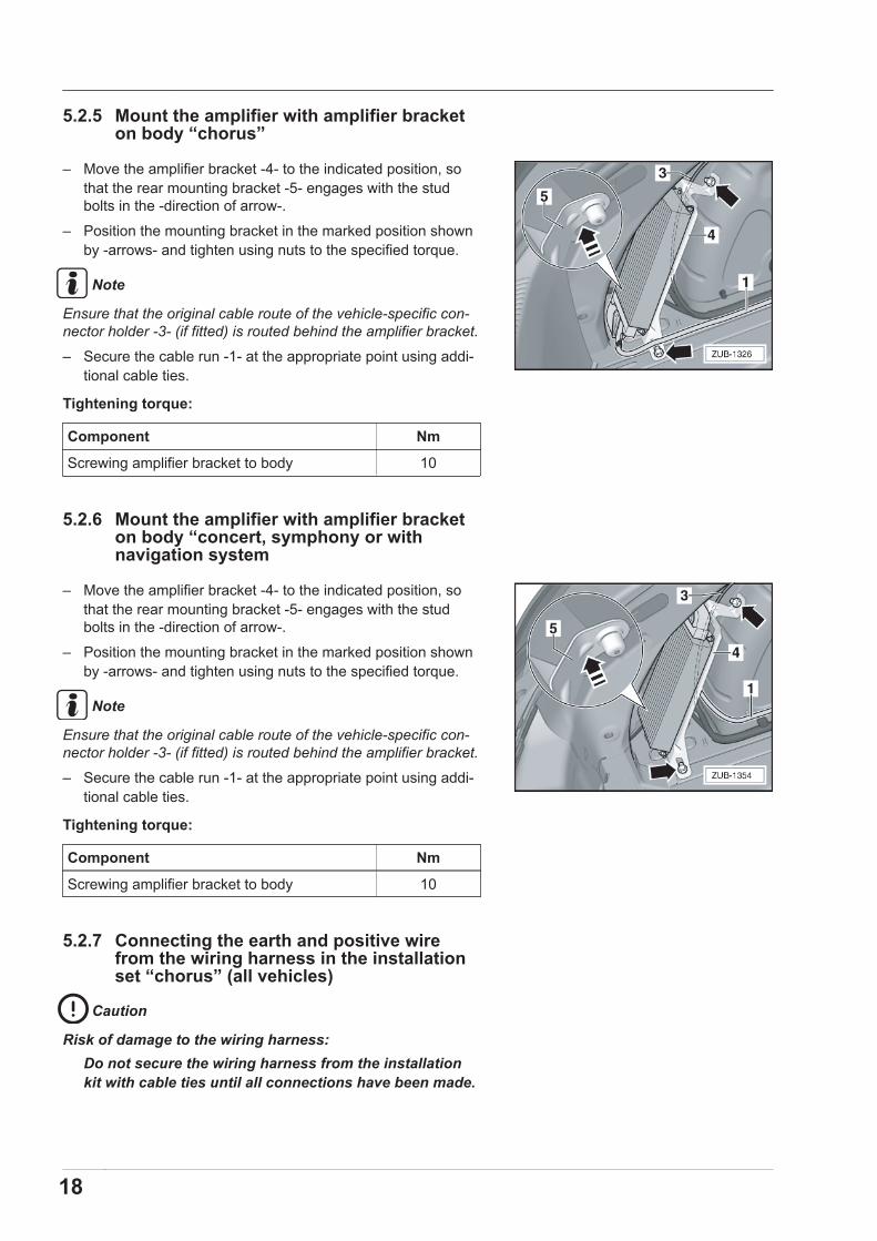
5.2.5 Mount the amplifier with amplifier bracketon body “chorus”
– Move the amplifier bracket -4- to the indicated position, sothat the rear mounting bracket -5- engages with the studbolts in the -direction of arrow-.
– Position the mounting bracket in the marked position shownby -arrows- and tighten using nuts to the specified torque.
Note
Ensure that the original cable route of the vehicle-specific con-nector holder -3- (if fitted) is routed behind the amplifier bracket.
– Secure the cable run -1- at the appropriate point using addi-tional cable ties.
Tightening torque:
Component Nm
Screwing amplifier bracket to body 10
5.2.6 Mount the amplifier with amplifier bracketon body “concert, symphony or withnavigation system
– Move the amplifier bracket -4- to the indicated position, sothat the rear mounting bracket -5- engages with the studbolts in the -direction of arrow-.
– Position the mounting bracket in the marked position shownby -arrows- and tighten using nuts to the specified torque.
Note
Ensure that the original cable route of the vehicle-specific con-nector holder -3- (if fitted) is routed behind the amplifier bracket.
– Secure the cable run -1- at the appropriate point using addi-tional cable ties.
Tightening torque:
Component Nm
Screwing amplifier bracket to body 10
5.2.7 Connecting the earth and positive wirefrom the wiring harness in the installationset “chorus” (all vehicles)
Caution
Risk of damage to the wiring harness:Do not secure the wiring harness from the installationkit with cable ties until all connections have been made.
18

Connecting the earth wire– Route the earth wire -1- from the wiring harness to the earth
point -2- and tighten using nuts to the specified torque -ar-row-.
5.2.8 Looping the positive wire into the standardfuse holder
Connecting the positive wire– The wire from the positive wire is pinned into standard fuse
harness, starting from the retrofit wiring harness.
– Pin the end of the wire into the open fuse slot -3-.
Connecting voltage supply to standard fuse holder– Connect the power supply connection wire from the standard
fuse holder to the positive pin of the vehicle battery.
19

5.3 Replacing the front left and right twee-ters (all vehicles)
Note
The tweeters are located on the right and left in the dashpanel.
The front left tweeter is removed and installed in thesame way as front right tweeter
Removal:– Install and remove the front left tweeter
Installation:– Install the tweeter using the TT2 adapter ring.
– The remaining installation is carried out in reverse order.
5.4 Installing the front left and right bassloudspeakers (all vehicles)
Note
The subwoofers are located in the right and left doors.
The front left subwoofer is removed and installed inthe same way as front right subwoofer .
Removal:– Remove and install the front left bass loudspeaker
Installation:– With the plug connector -1- upwards, position the bass loud-
speaker from the retrofit kit, incl. seal, at the inner door paneland tighten to torque using the existing screws.
Tightening torque Nm
Bass loudspeaker screw 3.5
Cable connection between mid-range loudspeaker andbass loudspeaker -> 5.5– The remaining installation is carried out in reverse order.
20

5.5 Connecting the front left and right mid-range loudspeakers (all vehicles)
Note
The front left and right mid-range loudspeakers are located inthe doors at the top.
Removal:– Prise the cover -1- for the inner door panel using a plastic
wedge -2-at the locations marked with -arrows- in the -direc-tion of the arrow-.
Installation:– Press in the well-nuts -1- at the locations marked with -ar-
rows- in a centred position -2-.
– Tighten the mid-range loudspeaker -1- using the screws pro-vided to the specified torque.
– Connect the front left and right mid-range loudspeaker to thebass loudspeaker.
– Connect the wire -1- with the flag -arrow- from the mid-rangeloudspeaker to the bass loudspeaker on the left-hand slot.
– Connect the wire -2- from the standard wiring harness to thebass loudspeaker.
Tightening torque Nm
Screw, mid-range loudspeaker 2
21

5.6 Attaching the debounce kit to the door,right and left (all vehicles)
Debounce kit on inner door panel, right and left:1 200 mm x 100 mm (2x)
2 200 mm x 50 mm (3x)
– Sections -2- must be cut from the pieces, 200 x 100, of thedebounce kit.
– Attach the debounce kit on the inner door panel at the indi-cated positions -1- and -2-.
Caution
Edges are very sharp during cutting.
Risk of injury
Debounce kit on door trim, right and left:– Cut the films from the debounce kit to the relevant sizes with
a box cutter or scissors.1 380 mm x 200 mm
2 100 mm x 75 mm
3 200 mm x 100 mm
4 100 mm x 75 mm
5 100 mm x 75 mm
– Attach the debounce kit to the door trim at the indicated po-sition.
22
5.7 Assembling the vehicleSequence of operations:– Connecting the battery
– Check the acoustic function of the “Audi Sound plus” systembefore assembling the vehicle.
The vehicle is assembled in the reverse order.
– Before delivering the vehicle, all regulators for the sound set-tings on the radio panel must be set to medium to guaranteeoptimum sound.
Note
Delete the fault memory if necessary
To prevent a fault memory entry in the area of the “soundamplifier” (Sound Verstärker), this entry must be uncoded inthe area of the “19th control device for gateway”.
When reading out the event memory, there may be static en-tries in the "Radio control unit loudspeaker" field. This willnot affect the system.
5.8 Returning the vehicleThe system functions must be explained to the customer whenreturning the vehicle.