preparation and characterization of the micro-arc ... · preparation and characterization of the...
TRANSCRIPT

HOSTED BY Available online at www.sciencedirect.com
ScienceDirect
Journal of Magnesium and Alloys 2 (2014) 309e316www.elsevier.com/journals/journal-of-magnesium-and-alloys/2213-9567
Full length article
Preparation and characterization of the micro-arc oxidation compositecoatings on magnesium alloys
Yanfeng Ge a,b,*, Bailing Jiang a,b, Ming Liu c, Congjie Wang d, Wenning Shen d
a Nanjing Tech University, No.30 South Puzhu Road, Nanjing 211816, Chinab Nanjing Haorang Environment Science &Technology CO., Ltd, No.30 South Puzhu Road, Nanjing 211816, China
c General Motors China Science Lab, No.56 Jinwan Road, Shanghai 201206, Chinad Xi'an University of Technology, No.5 South Jinhua Road, Xi'an 710048, China
Received 23 September 2014; revised 14 November 2014; accepted 18 November 2014
Available online 9 December 2014
Abstract
The magnesium alloys attract the light-weight manufacture due to its high strength to weight ratio, however the poor corrosion resistancelimits the application in automobile industry. The Micro-arc Composite Ceramic (MCC) coatings on AZ91D magnesium alloys were preparedby Micro-arc Oxidation (MAO) and electrophoresis technologies. The microstructure, corrosion resistance, abrasion resistance, stone impactresistance and adhesion of MCC coatings were studied respectively. The cross section morphologies showed that the outer organic coating wasfilled into the hole on surface of MAO coating, and it acted as a shelter against corrosive products. The copper-accelerated acetic acid salt sprayTest, abrasion resistance test, stone impact resistance test, thermal shock resistance test and adhesion test were used to evaluate the protectivecharacterization by the third testing organization which approved by GM. The test results showed the composite coatings meet all the re-quirements. The MCC coating on Mg presents excellent properties, and it is a promising surface treatment technology on magnesium alloys forproduction vehicles.Copyright 2014, National Engineering Research Center for Magnesium Alloys of China, Chongqing University. Production and hosting byElsevier B.V.
Keywords: AZ91D; Micro-arc oxidation; Electrophoresis; Composite coatings; Properties
Open access under CC BY-NC-ND license.
1. Introduction
Recently, limited fossil fuel and environmental problemshave promoted the use of lightweight material, such as mag-nesium, for automotive use in order to improve fuel economyconsumption and decreasing exhaust emissions [1,2].Magnesium-based alloys are of increasing attraction for manyindustrial applications on account of their low density, highspecific strength, good cast-ability, good weld-ability and
* Corresponding author. Nanjing Tech University, No.30 South Puzhu Road,
Nanjing 211816, China.
E-mail addresses: [email protected], [email protected] (Y. Ge).
Peer review under responsibility of National Engineering Research Center
for Magnesium Alloys of China, Chongqing University.
http://dx.doi.org/10.1016/j.jma.2014.11.006.
2213-9567/Copyright 2014, National Engineering Research Center for Magnesium Alloys of China, Cho
mechanical properties, especially in automotive production[3,4]. Porsche engineers striving to progressively reduce en-gine weight and refine part production selected magnesium forthe V6 and V8 engine front covers, using precisely the samelightweight cover part for both engine types. The front coverweighs just 2.14 kg, compared to 3.89 kg using an aluminumcover a 45 percent weight savings [5].
Unfortunately, magnesium has a number of undesirableproperties including poor corrosion and wear resistance, poorcreep resistance and high chemical reactivity. Magnesium andits alloys were extremely susceptible to galvanic corrosion,which can cause severe pitting in the metal resulting indecreased mechanical stability and an unattractive appearance[6]. Surface coating technology is one of the most effectivemethods to prevent magnesium from degradation [7,8].
ngqing University. Production and hosting by Elsevier B.V. Open access under CC BY-NC-ND license.
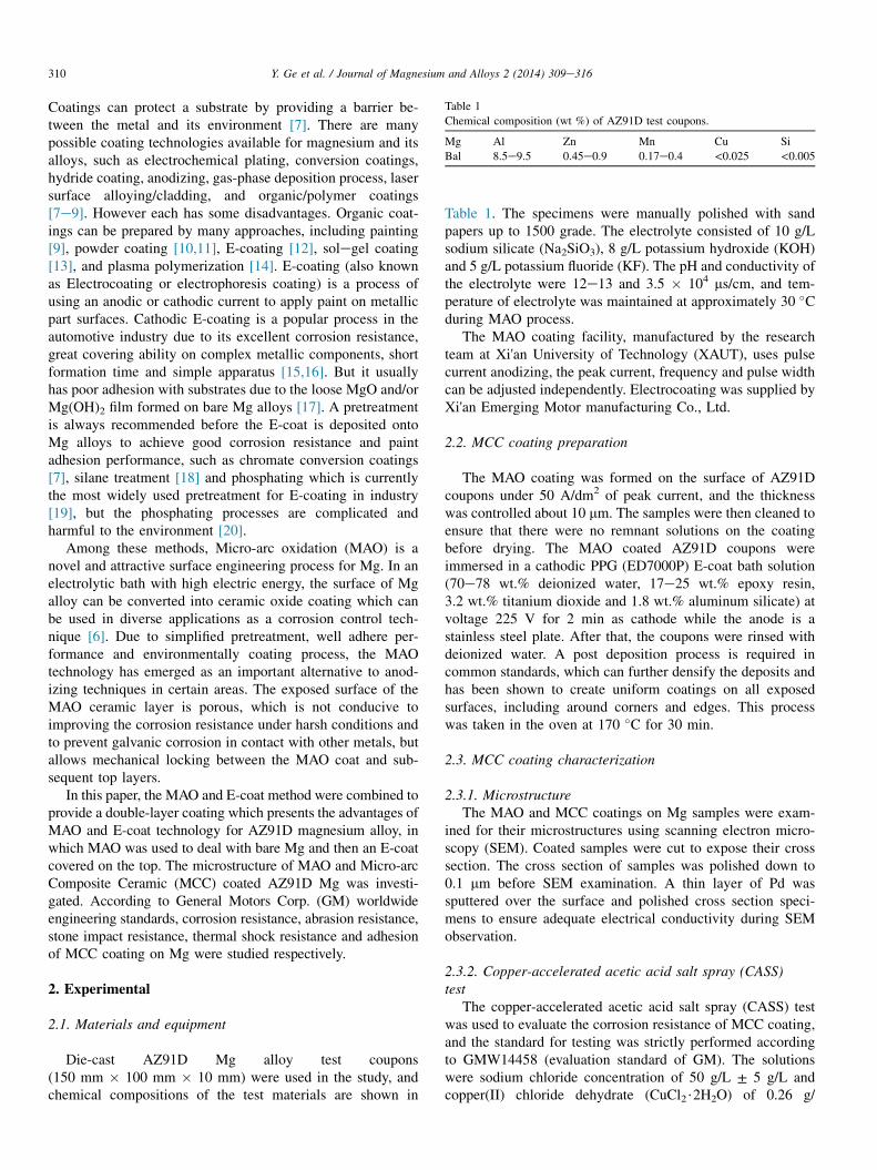
Table 1
Chemical composition (wt %) of AZ91D test coupons.
Mg Al Zn Mn Cu Si
Bal 8.5e9.5 0.45e0.9 0.17e0.4 <0.025 <0.005
310 Y. Ge et al. / Journal of Magnesium and Alloys 2 (2014) 309e316
Coatings can protect a substrate by providing a barrier be-tween the metal and its environment [7]. There are manypossible coating technologies available for magnesium and itsalloys, such as electrochemical plating, conversion coatings,hydride coating, anodizing, gas-phase deposition process, lasersurface alloying/cladding, and organic/polymer coatings[7e9]. However each has some disadvantages. Organic coat-ings can be prepared by many approaches, including painting[9], powder coating [10,11], E-coating [12], solegel coating[13], and plasma polymerization [14]. E-coating (also knownas Electrocoating or electrophoresis coating) is a process ofusing an anodic or cathodic current to apply paint on metallicpart surfaces. Cathodic E-coating is a popular process in theautomotive industry due to its excellent corrosion resistance,great covering ability on complex metallic components, shortformation time and simple apparatus [15,16]. But it usuallyhas poor adhesion with substrates due to the loose MgO and/orMg(OH)2 film formed on bare Mg alloys [17]. A pretreatmentis always recommended before the E-coat is deposited ontoMg alloys to achieve good corrosion resistance and paintadhesion performance, such as chromate conversion coatings[7], silane treatment [18] and phosphating which is currentlythe most widely used pretreatment for E-coating in industry[19], but the phosphating processes are complicated andharmful to the environment [20].
Among these methods, Micro-arc oxidation (MAO) is anovel and attractive surface engineering process for Mg. In anelectrolytic bath with high electric energy, the surface of Mgalloy can be converted into ceramic oxide coating which canbe used in diverse applications as a corrosion control tech-nique [6]. Due to simplified pretreatment, well adhere per-formance and environmentally coating process, the MAOtechnology has emerged as an important alternative to anod-izing techniques in certain areas. The exposed surface of theMAO ceramic layer is porous, which is not conducive toimproving the corrosion resistance under harsh conditions andto prevent galvanic corrosion in contact with other metals, butallows mechanical locking between the MAO coat and sub-sequent top layers.
In this paper, the MAO and E-coat method were combined toprovide a double-layer coating which presents the advantages ofMAO and E-coat technology for AZ91D magnesium alloy, inwhich MAO was used to deal with bare Mg and then an E-coatcovered on the top. The microstructure of MAO and Micro-arcComposite Ceramic (MCC) coated AZ91D Mg was investi-gated. According to General Motors Corp. (GM) worldwideengineering standards, corrosion resistance, abrasion resistance,stone impact resistance, thermal shock resistance and adhesionof MCC coating on Mg were studied respectively.
2. Experimental
2.1. Materials and equipment
Die-cast AZ91D Mg alloy test coupons(150 mm � 100 mm � 10 mm) were used in the study, andchemical compositions of the test materials are shown in
Table 1. The specimens were manually polished with sandpapers up to 1500 grade. The electrolyte consisted of 10 g/Lsodium silicate (Na2SiO3), 8 g/L potassium hydroxide (KOH)and 5 g/L potassium fluoride (KF). The pH and conductivity ofthe electrolyte were 12e13 and 3.5 � 104 ms/cm, and tem-perature of electrolyte was maintained at approximately 30 �Cduring MAO process.
The MAO coating facility, manufactured by the researchteam at Xi'an University of Technology (XAUT), uses pulsecurrent anodizing, the peak current, frequency and pulse widthcan be adjusted independently. Electrocoating was supplied byXi'an Emerging Motor manufacturing Co., Ltd.
2.2. MCC coating preparation
The MAO coating was formed on the surface of AZ91Dcoupons under 50 A/dm2 of peak current, and the thicknesswas controlled about 10 mm. The samples were then cleaned toensure that there were no remnant solutions on the coatingbefore drying. The MAO coated AZ91D coupons wereimmersed in a cathodic PPG (ED7000P) E-coat bath solution(70e78 wt.% deionized water, 17e25 wt.% epoxy resin,3.2 wt.% titanium dioxide and 1.8 wt.% aluminum silicate) atvoltage 225 V for 2 min as cathode while the anode is astainless steel plate. After that, the coupons were rinsed withdeionized water. A post deposition process is required incommon standards, which can further densify the deposits andhas been shown to create uniform coatings on all exposedsurfaces, including around corners and edges. This processwas taken in the oven at 170 �C for 30 min.
2.3. MCC coating characterization
2.3.1. MicrostructureThe MAO and MCC coatings on Mg samples were exam-
ined for their microstructures using scanning electron micro-scopy (SEM). Coated samples were cut to expose their crosssection. The cross section of samples was polished down to0.1 mm before SEM examination. A thin layer of Pd wassputtered over the surface and polished cross section speci-mens to ensure adequate electrical conductivity during SEMobservation.
2.3.2. Copper-accelerated acetic acid salt spray (CASS)test
The copper-accelerated acetic acid salt spray (CASS) testwas used to evaluate the corrosion resistance of MCC coating,and the standard for testing was strictly performed accordingto GMW14458 (evaluation standard of GM). The solutionswere sodium chloride concentration of 50 g/L ± 5 g/L andcopper(II) chloride dehydrate (CuCl2$2H2O) of 0.26 g/
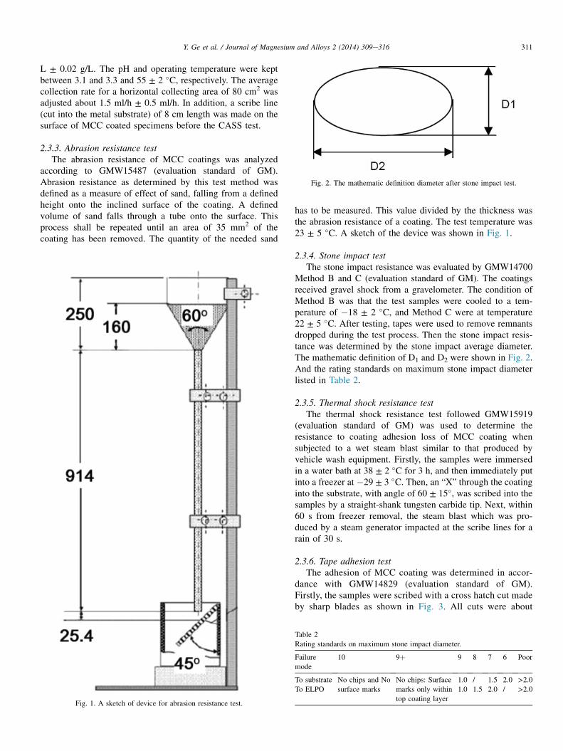
Fig. 2. The mathematic definition diameter after stone impact test.
311Y. Ge et al. / Journal of Magnesium and Alloys 2 (2014) 309e316
L ± 0.02 g/L. The pH and operating temperature were keptbetween 3.1 and 3.3 and 55 ± 2 �C, respectively. The averagecollection rate for a horizontal collecting area of 80 cm2 wasadjusted about 1.5 ml/h ± 0.5 ml/h. In addition, a scribe line(cut into the metal substrate) of 8 cm length was made on thesurface of MCC coated specimens before the CASS test.
2.3.3. Abrasion resistance testThe abrasion resistance of MCC coatings was analyzed
according to GMW15487 (evaluation standard of GM).Abrasion resistance as determined by this test method wasdefined as a measure of effect of sand, falling from a definedheight onto the inclined surface of the coating. A definedvolume of sand falls through a tube onto the surface. Thisprocess shall be repeated until an area of 35 mm2 of thecoating has been removed. The quantity of the needed sand
Fig. 1. A sketch of device for abrasion resistance test.
has to be measured. This value divided by the thickness wasthe abrasion resistance of a coating. The test temperature was23 ± 5 �C. A sketch of the device was shown in Fig. 1.
2.3.4. Stone impact testThe stone impact resistance was evaluated by GMW14700
Method B and C (evaluation standard of GM). The coatingsreceived gravel shock from a gravelometer. The condition ofMethod B was that the test samples were cooled to a tem-perature of �18 ± 2 �C, and Method C were at temperature22 ± 5 �C. After testing, tapes were used to remove remnantsdropped during the test process. Then the stone impact resis-tance was determined by the stone impact average diameter.The mathematic definition of D1 and D2 were shown in Fig. 2.And the rating standards on maximum stone impact diameterlisted in Table 2.
2.3.5. Thermal shock resistance testThe thermal shock resistance test followed GMW15919
(evaluation standard of GM) was used to determine theresistance to coating adhesion loss of MCC coating whensubjected to a wet steam blast similar to that produced byvehicle wash equipment. Firstly, the samples were immersedin a water bath at 38 ± 2 �C for 3 h, and then immediately putinto a freezer at �29 ± 3 �C. Then, an “X” through the coatinginto the substrate, with angle of 60 ± 15�, was scribed into thesamples by a straight-shank tungsten carbide tip. Next, within60 s from freezer removal, the steam blast which was pro-duced by a steam generator impacted at the scribe lines for arain of 30 s.
2.3.6. Tape adhesion testThe adhesion of MCC coating was determined in accor-
dance with GMW14829 (evaluation standard of GM).Firstly, the samples were scribed with a cross hatch cut madeby sharp blades as shown in Fig. 3. All cuts were about
Table 2
Rating standards on maximum stone impact diameter.
Failure
mode
10 9þ 9 8 7 6 Poor
To substrate No chips and No
surface marks
No chips: Surface
marks only within
top coating layer
1.0 / 1.5 2.0 >2.0To ELPO 1.0 1.5 2.0 / >2.0
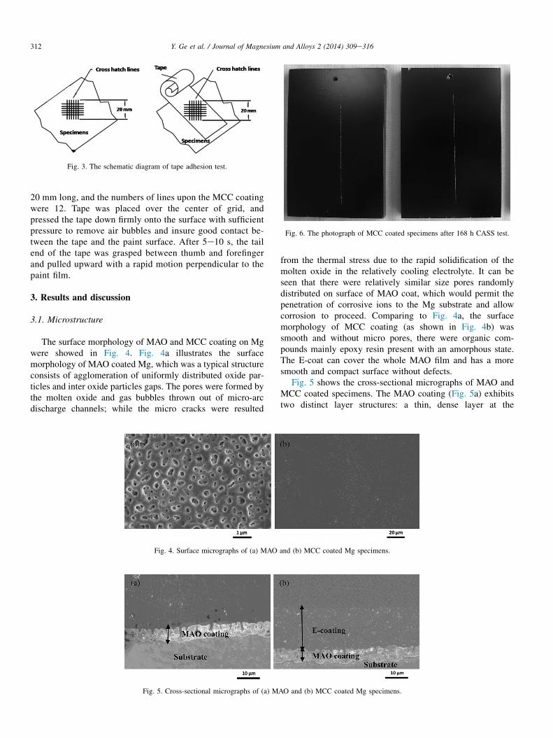
Fig. 3. The schematic diagram of tape adhesion test.
Fig. 6. The photograph of MCC coated specimens after 168 h CASS test.
312 Y. Ge et al. / Journal of Magnesium and Alloys 2 (2014) 309e316
20 mm long, and the numbers of lines upon the MCC coatingwere 12. Tape was placed over the center of grid, andpressed the tape down firmly onto the surface with sufficientpressure to remove air bubbles and insure good contact be-tween the tape and the paint surface. After 5e10 s, the tailend of the tape was grasped between thumb and forefingerand pulled upward with a rapid motion perpendicular to thepaint film.
3. Results and discussion
3.1. Microstructure
The surface morphology of MAO and MCC coating on Mgwere showed in Fig. 4. Fig. 4a illustrates the surfacemorphology of MAO coated Mg, which was a typical structureconsists of agglomeration of uniformly distributed oxide par-ticles and inter oxide particles gaps. The pores were formed bythe molten oxide and gas bubbles thrown out of micro-arcdischarge channels; while the micro cracks were resulted
Fig. 5. Cross-sectional micrographs of (a) M
Fig. 4. Surface micrographs of (a) MAO
from the thermal stress due to the rapid solidification of themolten oxide in the relatively cooling electrolyte. It can beseen that there were relatively similar size pores randomlydistributed on surface of MAO coat, which would permit thepenetration of corrosive ions to the Mg substrate and allowcorrosion to proceed. Comparing to Fig. 4a, the surfacemorphology of MCC coating (as shown in Fig. 4b) wassmooth and without micro pores, there were organic com-pounds mainly epoxy resin present with an amorphous state.The E-coat can cover the whole MAO film and has a moresmooth and compact surface without defects.
Fig. 5 shows the cross-sectional micrographs of MAO andMCC coated specimens. The MAO coating (Fig. 5a) exhibitstwo distinct layer structures: a thin, dense layer at the
AO and (b) MCC coated Mg specimens.
and (b) MCC coated Mg specimens.
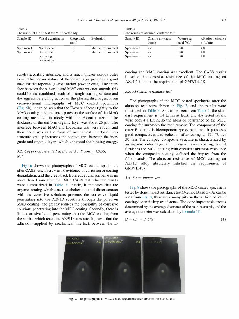
Table 4
The results of abrasion resistance test.
Sample ID Coating thickness
d(mm)
Volume test
sand V(L)
Abrasion resistance
s (L/mm)
Specimen 1 25 120 4.8
Specimen 2 25 120 4.8
Specimen 3 25 120 4.8
Table 3
The results of CASS test for MCC coated Mg.
Sample ID Visual examination Creep back
(mm)
Evaluation
Specimen 1 No evidence
of corrosion
or coating
degradation
1.0 Met the requirement
Specimen 2 1.0 Met the requirement
313Y. Ge et al. / Journal of Magnesium and Alloys 2 (2014) 309e316
substrate/coating interface, and a much thicker porous outerlayer. The porous nature of the outer layer provides a goodbase for the topcoats (E-coat and/or powder coat). The inter-face between the substrate and MAO coat was not smooth, thiscould be the combined result of a rough starting surface andthe aggressive etching action of the plasma discharges. Fromcross-sectional micrographs of MCC coated specimens(Fig. 5b), it can be seen that the E-coats adheres tightly to theMAO coating, and the open pores on the surface of the MAOcoating are filled in nicely with the E-coat material. Thethickness of the uniform organic layer was about 20 mm. Theinterface between MAO and E-coating was very rough, andtheir bond was in the form of mechanical interlock. Thisstructure greatly increases the contact area between the inor-ganic and organic layers which enhanced the binding energy.
3.2. Copper-accelerated acetic acid salt spray (CASS)test
Fig. 6 shows the photographs of MCC coated specimensafter CASS test. There was no evidence of corrosion or coatingdegradation, and the creep back from edges and scribes was nomore than 1 mm after the 168 h CASS test. The test resultswere summarized in Table 3. Firstly, it indicates that theorganic coating which acts as a shelter to avoid direct contactwith the corrosive solutions prevents the corrosive liquidpenetrating into the AZ91D substrate through the pores onMAO coating, and greatly reduces the possibility of corrosivesolutions penetrating into the MCC coating. Secondly, there islittle corrosive liquid penetrating into the MCC coating fromthe scribes which reach the AZ91D substrate. It proves that theadhesion supplied by mechanical interlock between the E-
Fig. 7. The photographs of MCC coated sp
coating and MAO coating was excellent. The CASS resultsillustrate the corrosion resistance of the MCC coating onAZ91D has met the requirement of GMW14458.
3.3. Abrasion resistance test
The photographs of the MCC coated specimens after theabrasion test were shown in Fig. 7, and the results wereillustrated in Table 3. As can be seen from Table 4, the stan-dard requirement is 1.4 L/mm at least, and the tested resultswere both 4.8 L/um, so the abrasion resistance of the MCCcoating far surpasses the requirement. The component of theouter E-coating is bicomponent epoxy resin, and it possessesgood compactness and cohesion after curing at 170 �C for30 min. The compact composite structure is characterized byan organic outer layer and inorganic inner coating, and itfurnishes the MCC coating with excellent abrasion resistancewhen the composite coating suffered the impact from thefallen sands. The abrasion resistance of MCC coating onAZ91D alloy absolutely satisfied the requirement ofGMW15487.
3.4. Stone impact test
Fig. 8 shows the photographs of the MCC coated specimenstestedby stone impact resistance test (MethodBandC).As canbeseen from Fig. 8, there were many pits on the surface of MCCcoating due to the impact of stones. The stone impact resistance isdetermined by the average diameter of the maximum pit, and theaverage diameter was calculated by formula (1):
D¼ D1 þD2ð Þ=2 ð1Þ
ecimens after abrasion resistance test.
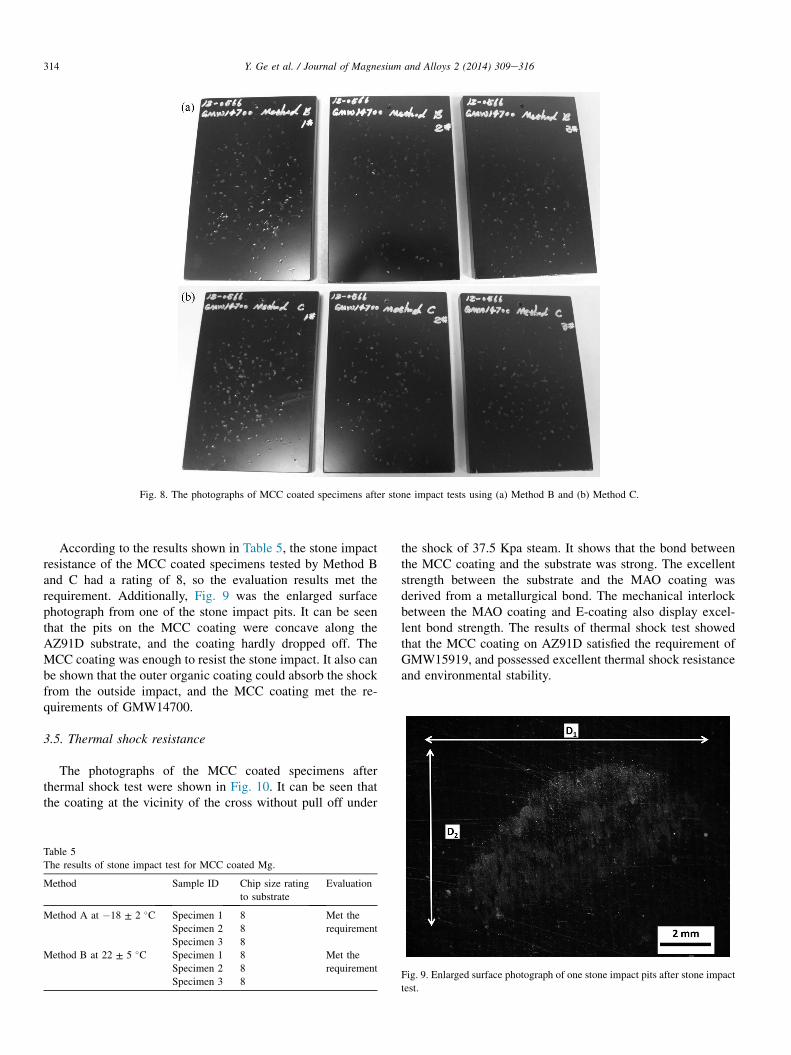
Fig. 8. The photographs of MCC coated specimens after stone impact tests using (a) Method B and (b) Method C.
314 Y. Ge et al. / Journal of Magnesium and Alloys 2 (2014) 309e316
According to the results shown in Table 5, the stone impactresistance of the MCC coated specimens tested by Method Band C had a rating of 8, so the evaluation results met therequirement. Additionally, Fig. 9 was the enlarged surfacephotograph from one of the stone impact pits. It can be seenthat the pits on the MCC coating were concave along theAZ91D substrate, and the coating hardly dropped off. TheMCC coating was enough to resist the stone impact. It also canbe shown that the outer organic coating could absorb the shockfrom the outside impact, and the MCC coating met the re-quirements of GMW14700.
3.5. Thermal shock resistance
The photographs of the MCC coated specimens afterthermal shock test were shown in Fig. 10. It can be seen thatthe coating at the vicinity of the cross without pull off under
Table 5
The results of stone impact test for MCC coated Mg.
Method Sample ID Chip size rating
to substrate
Evaluation
Method A at �18 ± 2 �C Specimen 1 8 Met the
requirementSpecimen 2 8
Specimen 3 8
Method B at 22 ± 5 �C Specimen 1 8 Met the
requirementSpecimen 2 8
Specimen 3 8
the shock of 37.5 Kpa steam. It shows that the bond betweenthe MCC coating and the substrate was strong. The excellentstrength between the substrate and the MAO coating wasderived from a metallurgical bond. The mechanical interlockbetween the MAO coating and E-coating also display excel-lent bond strength. The results of thermal shock test showedthat the MCC coating on AZ91D satisfied the requirement ofGMW15919, and possessed excellent thermal shock resistanceand environmental stability.
Fig. 9. Enlarged surface photograph of one stone impact pits after stone impact
test.
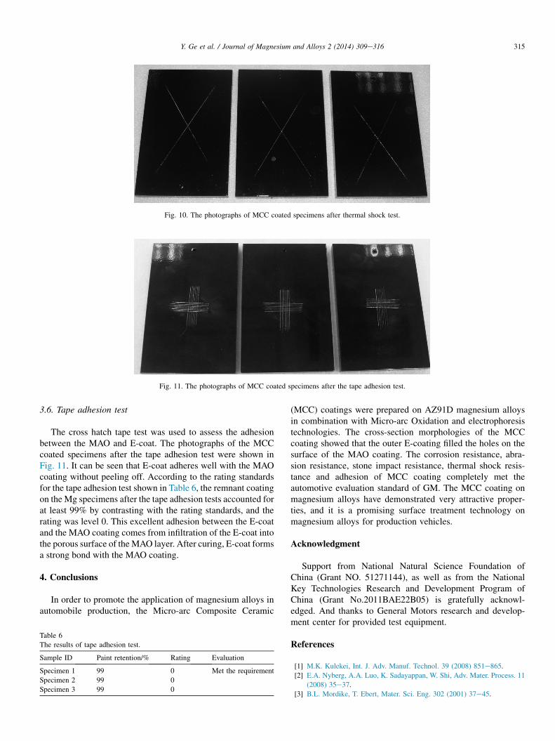
Fig. 10. The photographs of MCC coated specimens after thermal shock test.
Fig. 11. The photographs of MCC coated specimens after the tape adhesion test.
315Y. Ge et al. / Journal of Magnesium and Alloys 2 (2014) 309e316
3.6. Tape adhesion test
The cross hatch tape test was used to assess the adhesionbetween the MAO and E-coat. The photographs of the MCCcoated specimens after the tape adhesion test were shown inFig. 11. It can be seen that E-coat adheres well with the MAOcoating without peeling off. According to the rating standardsfor the tape adhesion test shown in Table 6, the remnant coatingon the Mg specimens after the tape adhesion tests accounted forat least 99% by contrasting with the rating standards, and therating was level 0. This excellent adhesion between the E-coatand the MAO coating comes from infiltration of the E-coat intothe porous surface of theMAO layer. After curing, E-coat formsa strong bond with the MAO coating.
4. Conclusions
In order to promote the application of magnesium alloys inautomobile production, the Micro-arc Composite Ceramic
Table 6
The results of tape adhesion test.
Sample ID Paint retention/% Rating Evaluation
Specimen 1 99 0 Met the requirement
Specimen 2 99 0
Specimen 3 99 0
(MCC) coatings were prepared on AZ91D magnesium alloysin combination with Micro-arc Oxidation and electrophoresistechnologies. The cross-section morphologies of the MCCcoating showed that the outer E-coating filled the holes on thesurface of the MAO coating. The corrosion resistance, abra-sion resistance, stone impact resistance, thermal shock resis-tance and adhesion of MCC coating completely met theautomotive evaluation standard of GM. The MCC coating onmagnesium alloys have demonstrated very attractive proper-ties, and it is a promising surface treatment technology onmagnesium alloys for production vehicles.
Acknowledgment
Support from National Natural Science Foundation ofChina (Grant NO. 51271144), as well as from the NationalKey Technologies Research and Development Program ofChina (Grant No.2011BAE22B05) is gratefully acknowl-edged. And thanks to General Motors research and develop-ment center for provided test equipment.
References
[1] M.K. Kulekei, Int. J. Adv. Manuf. Technol. 39 (2008) 851e865.
[2] E.A. Nyberg, A.A. Luo, K. Sadayappan, W. Shi, Adv. Mater. Process. 11
(2008) 35e37.
[3] B.L. Mordike, T. Ebert, Mater. Sci. Eng. 302 (2001) 37e45.

316 Y. Ge et al. / Journal of Magnesium and Alloys 2 (2014) 309e316
[4] H.A. Patel, D.L. Chen, S.D. Bhole, K. Sadayappan, J. Alloys Compd.
496 (2010) 140e148.
[5] Wang Congjie, Jiang Bailing, Liu Ming, Ge Yanfeng, J. Alloys Compd.
21 (2015) 53e61.
[6] J.E. Gray, B. Luan, J. Alloys Compd. 336 (2002) 88e113.
[7] C. Zhong, F. Liu, Y.T. Wu, J.J. Le, L. Liu, M.F. He, J.C. Zhu, W.B. Hu, J.
Alloys Compd. 520 (2012) 11e21.
[8] R.G. Hu, S. Zhang, J.F. Bu, C.J. Lin, G.L. Song, Pro. Org. Coat. 73
(2012) 129e141.
[9] H. Umehara, M. Takaya, T. Itoh, J. Jpn. Inst. Light Met. 48 (2005)
248e255.
[10] A. Drian, G. Bailey, J. Electrost. 45 (2002) 85e120.[11] M. Bestetti, P.L. Cavallotti, A. Da Fomo, S. Pozzi, Trans. Inst. Met.
Finish. 85 (2007) 316e319.
[12] A. Bakkar, V. Neubert, Electrochem. Commun. 9 (2007) 2428e2435.
[13] A.J. L�opez, J. Rams, A. Ure~na, Surf. Coat. Technol. 205 (2011)
4183e4191.
[14] S.V. Gnedenkov, S.L. Sinebryukhov, D.V. Mashtalyar, V.S. Egorkin,
M.V. Idorova, A.S. Gendenkov, Corros. Sci. 85 (2014) 52e59.[15] G.L. Song, Electrochim. Acta 55 (2010) 2258e2268.
[16] L. Besra, M. Liu, Prog. Mater. Sci. 52 (2007) 1e61.
[17] A. Bakkar, V. Neubert, Corros. Sci. 49 (2007) 1110e1130.[18] J. Zhang, C.Y. Wu, Pro. Org. Coat. 66 (2009) 387e392.
[19] G.Y. Li, J.S. Lian, L.Y. Niu, Z.H. Jiang, H. Dong, Surf. Eng. 23 (2007)
56e61.
[20] X.J. Cui, C.H. Liu, R.S. Yang, Q.S. Fu, X.Z. Lin, M. Gong, Corros. Sci.
76 (2013) 474e485.