preparation and properties of nanostructured magnetic ... · preparation and properties of...
TRANSCRIPT
Phase Transitions
Vol. 00, No. 00, January 2005, 1–9
Preparation and properties of nanostructured magnetic hollow
microspheres: Experiment and simulation
A. SCHLACHTER, M. E. GRUNER∗, M. SPASOVA, M. FARLE, and P. ENTEL
Fachbereich Physik, Universitat Duisburg-Essen, Lotharstraße 1, 47048 Duisburg,
Germany
(15 July 2005)
This paper presents the experimental realization of magnetic hollow microspheres. Starting fromcore-shell microspheres with an organic core and a shell composed of nanoparticles, we could removethe core using a plasma etching technique. An estimate of the magnetoelastic effects arising fromthe interplay of magnetic dipolar interactions and cohesive energy which can be expected in suchstructures is given with the help of computer simulations using the Hybrid Monte Carlo method.
Keywords: hollow microspheres; magnetic nanoparticles; plasma etching; Monte Carlo simulations;magnetic dipole coupling
1 Introduction
Magnetic hollow microspheres with tunable shell thickness and compositionare interesting building blocks for new advanced materials with a lot of po-tential applications. Their properties are determined by the nanosized compo-nents which constitute the shell material. The structures can be synthesisedusing self assembly easing the mass production process (see e.g. [1, 2]).
One possible application for hollow microspheres are photonic crystals [3].Controlling the difference of the refractive index of the shell and the core andalso the arrangement of the balls on a regular three-dimensional lattice, onecan obtain colloidal crystals with full photonic band gap in the visible [4, 5].
Magnetic nanoparticles also find a lot of applications in the medical area[6–8], for example in diagnostics or drug targeting by magnetically guided
∗Corresponding author. E-mail: [email protected]
Phase Transitions
ISSN 0141-1594 print/ ISSN 1029-0338 online c©2005 Taylor & Francis Ltd
http://www.tandf.co.uk/journals
DOI: 10.1080/014115940xxxxxxxxxxxx
2 A. Schlachter, M. E. Gruner, M. Spasova, M. Farle, and P. Entel
transport [9–11]. Magnetic hollow capsules could be very useful for such a drugdelivery system: By filling the particles with drugs and directing them by aninhomogeneous magnetic field into the immediate vicinity of a tumor, the dosiscould be reduced and the drugs would not affect other regions of the body.Iron oxide hollow spheres in aqueous solution are appropriate biocompatiblecarriers for this purpose. Another possible application is the use as actuatorsin small magnetomechanical devices, which could be operated by externalmagnetic fields in places where electrical or mechanical connections to theoutside world are not desirable (e. g. inside the human body).
The fabrication of hollow spheres was previously realized by other groupsvia calcination, a time consuming process of many hours [12–15]. On theother hand, organic components surrounding core-shell nanoparticles can beremoved in a matter of minutes by exposure to suitable plasmas [16]. Therehave also been reports on the synthesis of metallodielectric composite particleswith multishell structure, especially for photonic crystal applications [17,18].
The first part of our paper explains how hollow magnetic nanospheres canbe fabricated experimentally in an efficient way, and the structural propertiesof the compounds are presented. The second part adresses the magnetic andmagnetoelastic properties of such structures by means of computer simula-tions.
2 Experimental preparation
2.1 Preparation of core-shell microspheres
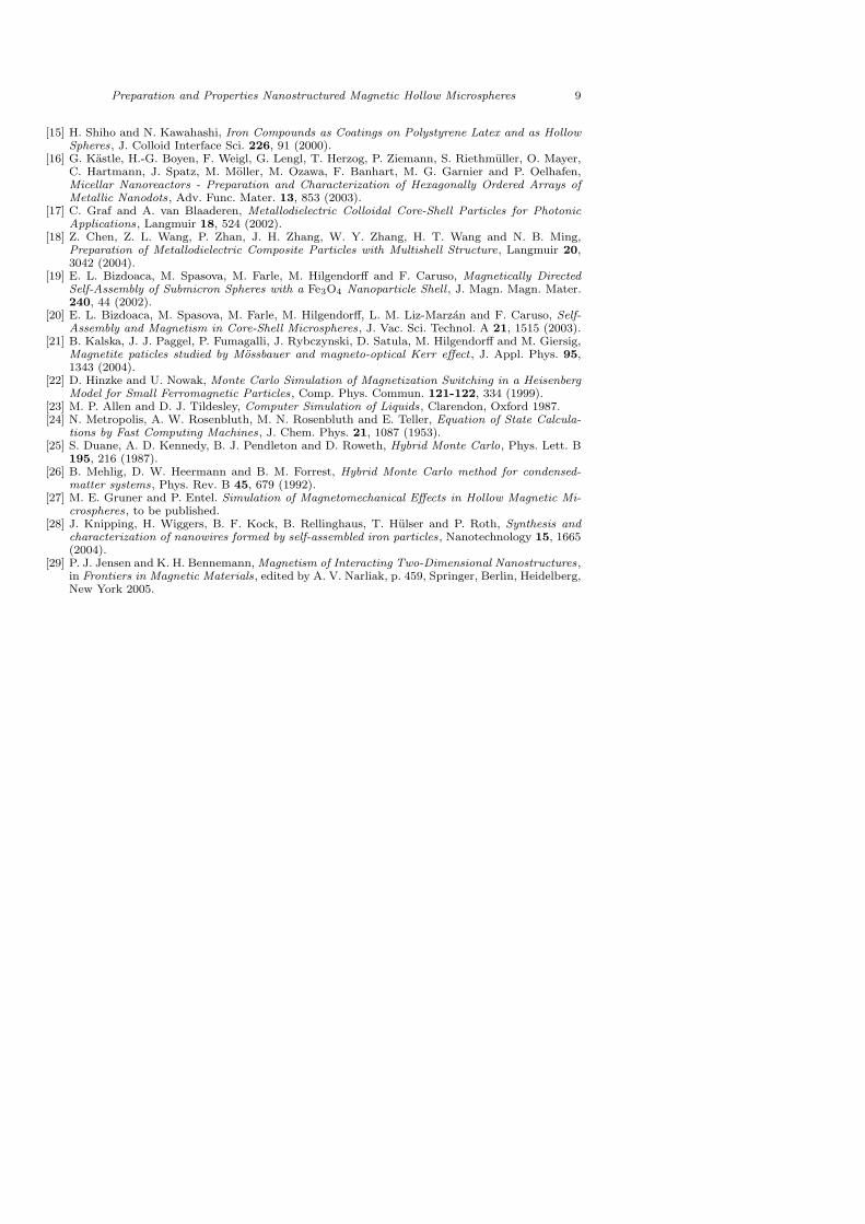
The core-shell microspheres were fabricated by the layer-by-layer method.Driven by electrostatic forces, the nanometre sized particles assemble in anaqueous suspension on the spherical surface of micrometer sized beads. Thepreparation of these particles and magnetic characterisation has been de-scribed elsewhere [12, 19, 20]. We used polystyrene (PS) beads with diame-ters of 590 nm and 640 nm and nanoparticles of Fe3O4 (Ø = 12 ± 3 nm) andMn0.5Fe2.5O4 (Ø = 10 ± 3 nm). The properties of the nanoparticles buildingthe shell of the core-shell particles were reported elsewhere [21]. Drops of thesuspension containing the core-shell microspheres were deposited on Si wafersubstrates. The left panel of Fig. 1 shows such a microsphere on a Si substrate.
2.1.1 Plasma etching of core-shell particles. To remove the organic com-ponents of the sample and thus the core of the microspheres, we used a planartype inductively coupled plasma (ICP). A cylindrical Pyrex chamber (mountedon a steel vacuum chamber) and a grounded and perforated aluminium plateconfine the plasma. On the top and outside of the Pyrex chamber the induction
Preparation and Properties Nanostructured Magnetic Hollow Microspheres 3
coil was situated. A Faraday shield, consisting of a copper ring with copperstrips stretching inward, was mounted between this coil and the Pyrex plateto prevent capacitive coupling between the induction coil and the plasma. Themagnetic field lines penetrate the Faraday shield inducing inside the chamberan alternating electric field. The oxygen gas pressure was 0.13 mbar, whichresulted in chemical plasma etching and prevented the ion assisted damageof the material and physical sputtering. The RF-generator had an operatingfrequency of 13.56 MHz amplified to an output power of 250 W. The etchingtimes were 10 to 120 minutes in 10 minutes steps. The samples were placedin the middle of the discharge onto an aluminium holder, which was isolatedagainst the aluminium plate.
2.1.2 Characterisation. The diameters of the microspheres were deter-mined from scanning electron micrographs (SEM), using a LEO 1530 SEMapplying an accelerating voltage of 10 kV . Energy dispersive X-ray (EDX)spectroscopy linescan measurements were performed on a Philips Tecnai G230 transmission electron microscope (TEM) with 300 kV accelerating voltage.
2.2 Results and discussion
2.2.1 Structural analysis. Structural analysis was performed by SEM (cf.Fig. 1). The left panel of Fig. 1 shows a microsphere before etching. The plasmatreatment leaves the shell intact without substantial changes to the structure.The microsphere in the right panel of Fig. 1 was deliberately opened to demon-strate the absence of the core. One can see that the nanoparticles of the shellare partly sintered. However, the shell is still porous, which explains the diffu-sion of oxidised, gaseous organic material from the core. SEM-images taken at45◦ inside the microscope confirmed, that the spheres are stable and sphericalafter plasma treatment. Analysis of the same particle before and after etchingshowed a reduction of the diameter by less than 5 %. The expected changeof diameter due to the removal of the polyelectrolytes spacers (approximately5 nm) between the nanoparticle-layers for a total shell thickness of 165 nm is8 %. On the other hand, one also has to consider the complete oxidation ofthe shell-forming nanoparticles (maghemite and magnetite) to haematite lead-ing to a change in volume. Oxidation from magnetite to haematite results inan increase in volume by 2 %, from maghemite to haematite in a decrease of7 % respectively. At present, our measurements are not accurate enough tomake definitive conclusions about the composition of the shell and the spacingbetween the nanoparticles.
TEM-measurements showed the cristallinity of the shell-forming nanopar-ticles before and after plasma treatment. This was confirmed by X-ray
4 A. Schlachter, M. E. Gruner, M. Spasova, M. Farle, and P. Entel
diffraction (XRD) measurements, showing that the shell material consists ofhaematite after plasma treatment. However, to improve the magnetic prop-erties a magnetite core-shell structure would be desirable, which could beobtained by reduction in a H plasma [15,16].
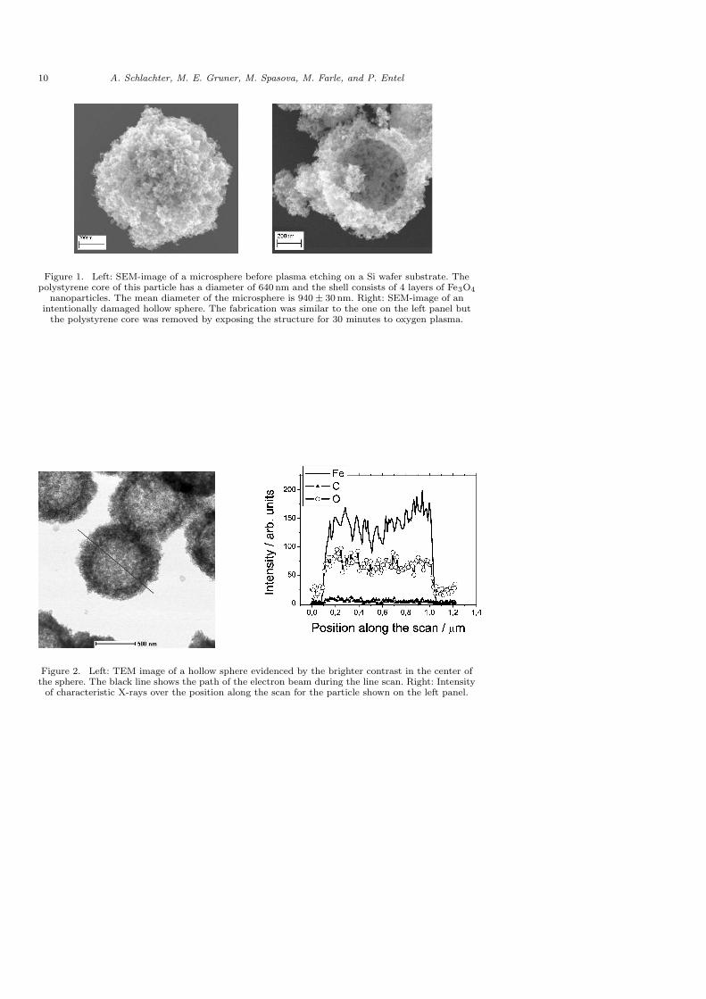
2.2.2 Composition analysis. The composition of the particles was analysedby EDX linescans in the TEM. The intensities of the characteristic Kα-linesof iron, oxygen and carbon were plotted against the position of the incidentelectron beam along the scan across the microsphere (see fig. 2). The figureshows the results for particles with a core-diameter of 640 nm and 4 layers ofnano-haematite, after an etching time of 30 minutes. The iron signal shows twomaxima at the side corresponding to the position of maximal excitation volumefor the X-rays. These two maxima are characteristic for a core-shell structure.This effect is also seen somewhat weaker in the oxygen signal. The oxygenbackground signal is due to the amorphous SiO substrate. The carbon signalis zero, which proves the complete removal of the PS ([−CH2CH(C6H5)−]n)core.
3 Simulation of magnetoelastic properties
The experimental determination of magnetomechanic properties of nanopar-ticle ensembles on curved surfaces like hollow spheres is a problem, which hasnot been solved so far. With the aid of computer simulations of nanocompos-ite structures, however, one may hope to close this gap. In the following, wepresent a computer model for the description of such properties.
3.1 The model
We consider magnetic core-shell nanoparticles in a closed packed arrangementon the surface of a sphere. The investigated structure has a diameter of about240 nm and contains N = 1496 individual nanoparticles. The thickness of thesurface shell is about 34 nm (3 monolayers) which renders the structure stablefor at least several µs of simulation time. Each nanoparticle consists of a Fe3O4
(magnetite) core of 12 nm and a nonmagnetic shell (thickness 1 nm).We describe the system by a Hamiltonian with spatial and vector spin de-
grees of freedom in a homogeneous magnetic field ~B:
H = Hdipole + HLJ − ~B∑
i
~µi . (1)
Preparation and Properties Nanostructured Magnetic Hollow Microspheres 5
The first term describes the magnetic dipole interactions between two Fe3O4
nanoparticles:
Hdipole =∑
i>j
µ0
4π
(
~µi ~µj
r3ij
− 3(~µi ~rij) (~rij ~µj)
r5ij
)
. (2)
Due to their long range spatial extension the interactions between all particleshave to be considered leading to an unfavourable N 2 scaling of the computa-tion time with the system size limiting the range of treatable system sizes to afew thousand particles. The magnetic moments µi are set to 4×10⁴ µB, whichis a reasonable value for Fe3O4 nanoparticles of this size.
The second term describes the attractive van-der-Waals-like interactions andthe repulsive term with the help of Lennard-Jones-type pair potentials
HLJ =∑
i>j
3
43 3√
4ε
[
(
σ
rij
)24
−(
σ
rij
)6]
. (3)
To better suite the hard sphere nature of the nanoparticles a power of 24is used for the repulsive part of the potential. The parameter ε describes thebinding energy, while σ is fixed by the equilibrium distance of two particles. Inour simulations, we investigated particles with binding energies of ε=0.125 eV,ε=0.25 eV and ε=0.50 eV.
3.2 Computational method
A convenient way to handle coupled magnetic and spatial degrees of freedomis by means of Monte Carlo (MC) Simulations. This is usually done usinga single step algorithm, changing the direction of the moment [22] and theposition [23] of each individual particle alternatingly, by choosing a new trialvalue and accepting or rejecting it according to the Metropolis criterion [24].
For the magnetic system, equilibrium is achieved after a few hundred latticesweeps. The convergence of the spatial degrees of freedom, however, takesmuch longer. In order to speed up this process, we employ the Hybrid-Monte-Carlo Method [25,26] for the updates of the particle positions, which includesan additional global update step for the translational degrees of freedom byintegrating Newton’s equation over 10 time steps by means of constant energymolecular dynamics, which also provides us with a natural time scale. Furtherdetails of the simulation method will be given elsewhere [27].
6 A. Schlachter, M. E. Gruner, M. Spasova, M. Farle, and P. Entel
3.3 Results
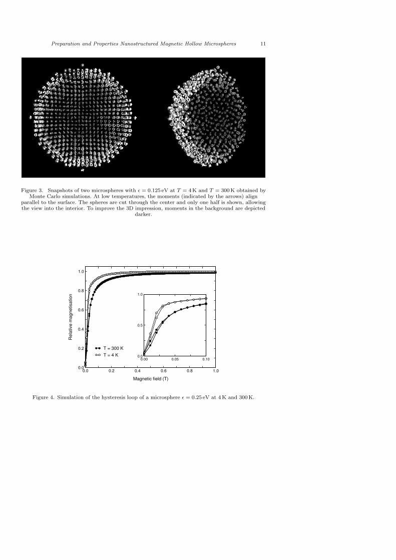
Fig. 3 shows a half opened microsphere after cooling it down over 50 000 MCsweeps with an exponential cooling rate from room temperature to T = 4 Kand subsequent stepwise heating up to room temperature over 120 000 MCsweeps (which equals approximatively 0.5 µs on a real time scale). Due to thenon-isotropic nature of the magnetic dipole interaction (2) the energy is low-ered, when moments located along the directions of their magnetisations arealigned in parallel with each other. On the other hand, antiparallel alignmentis preferred when the distance vector points perpendicular to the orientationof the moments. Therefore, free particles tend to agglomerate in chain struc-tures, as can be observed in experiments [19,20,28]. Since such a configurationis not possible on a surface of a sphere, at low temperatures the typical vortex-like moment structure evolves with moments aligned parallel to the surface ofthe sphere further stabilising the shell structure and leading to a vanishingoverall magnetic moment of the system (for a detailed review on the magneticproperties of mainly dipolar coupled magnetic nanosystems see [29]).
Increasing the field leads to a soft magnetic behaviour by successively align-ing more and more moments (Fig. 4). Saturation is reached after a few hundredmT. Upon reducing the field, a hysteresis is not clearly observable. The finiteslope of the magnetisation curve is due to the fact, that depending on theirlocation on the surface of the sphere, different amounts of energy are neededfor aligning the moments. Especially at the poles, the moments are forcedto a direction perpendicular to their equilibrium orientation, while the parti-cles around the equator may rotate into the field direction and still retain anorientation parallel to the surface.
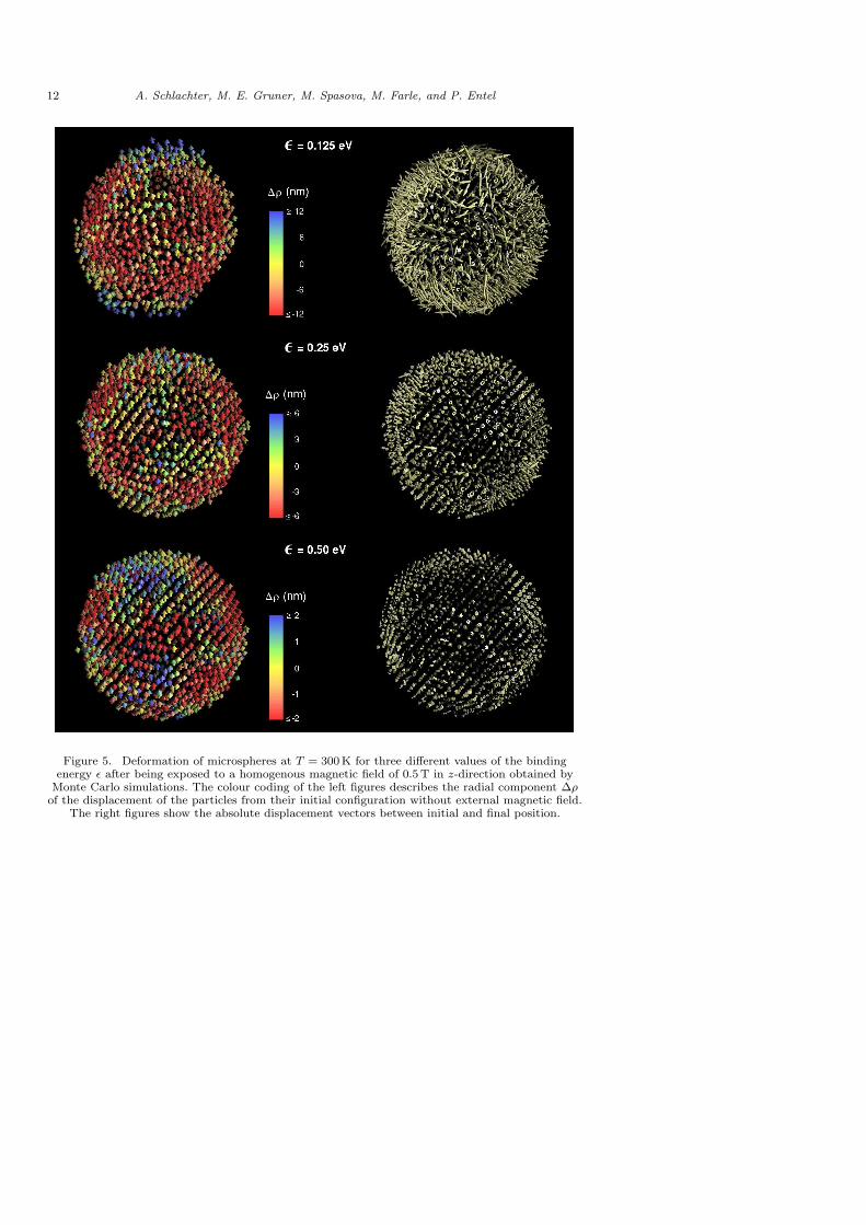
Since the dipole interaction (2) depends on the distance and the magneticorientation of the involved particles, applying a magnetic field will cause ad-ditional forces between the particles, which vary for different regions of thesphere. Thus, if the dipolar interaction is strong enough compared to the sta-bilising elastic potentials (3), the nanocomposite may considerably deform.Fig. 5 gives an impression of this effect. Here, three particles with differentvalues for the binding energy ε are shown which have been exposed to a ho-mogeneous magnetic field of 0.5 T at room temperature. The colour codingdescribes the radial displacement
∆ρ = ρ(B) − ρ(0) = |~r − 〈~r〉|B − |~r − 〈~r〉|0 , (4)
i. e. the difference in their distance to the centre of mass of the compositestructure. In addition, also the absolute displacement vectors to the initialequilibrium configurations without external magnetic field are plotted, show-ing the magnitudes of the individual particle movement. Particles at the poles
Preparation and Properties Nanostructured Magnetic Hollow Microspheres 7
are mainly displaced outwards, while particles around the equator move pri-marily towards the centre of the microsphere. This behaviour can be relatedto the tendency towards chain formation, which is typical for dipolar systems,as stated above. The observed effect is larger the smaller the binding energy ε.For ε = 0.125 eV displacements are obtained, which may be sufficient for tech-nical applications. However, at low binding energies, we also find an increasedparticle migration, which finally may cause the destruction of the nanocom-posite, e. g. through hole formation in the shell, as can be seen in the upperpanel of Fig. 5.
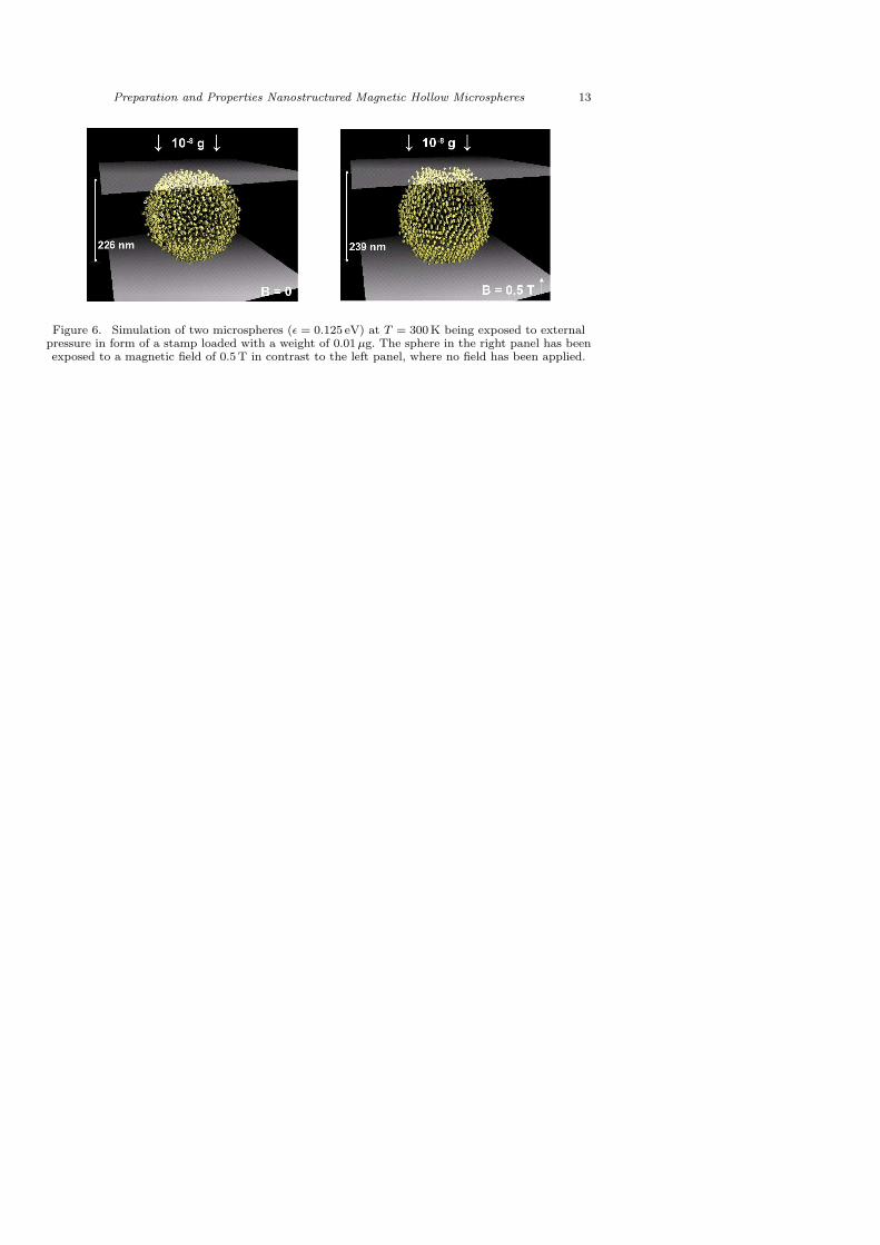
To further explore the influence of magnetism on the elastic properties,we exposed the nanocomposites to an external pressure in form of a stamppressing on the microsphere. Fig. 6 shows the comparison of two identicalparticles loaded with a weight of 0.01 µg after 150 000 MC sweeps, where oneof them has been exposed to a magnetic field of 0.5 T before the applicationof pressure. The dipolar forces deforming the particle due to their tendencytowards chain like arrangements of the moments also increase its ability towithstand external pressure, if the field is applied parallel to the direction ofthe force, maintaining a 6 % larger stamp height for the particle on the rightpanel of Fig. 6.
4 Conclusion
Hollow magnetic microspheres were fabricated from precursor core-shell par-ticles by plasma treatment. The submicron polystyrene cores were completelyremoved from the composite core-shell spheres by 30 min oxygen plasma etch-ing that results in fabrication of intact spherical magnetic capsules on differentsubstrates.
The computer simulations of magnetic hollow microspheres show that dipo-lar forces between the individual magnetic particles play an important role forthe materials properties. They lead to considerable magnetoelastic effects inexternal magnetic fields, especially for composites with small adhesive forcesbetween the nanoparticles. However, further simulations suggest that the de-formations caused by large magnetic fields may be non-reversible, even forlarger binding energies of ε = 0.25 eV and above, thus limiting their tech-nical usefulness. Technical applications not intending the destruction of theparticle (which could nevertheless be desirable, e. g. for biomedical applica-tions) should therefore not take place in the regime of strong magnetic fieldsclose to the saturation field. Larger sphere diameters and larger shell thick-nesses may improve the stability. Systematic investigations of the influence ofsphere geometry on the magnetoelastic properties are, however, impaired bythe quadratic scaling of the computation time with the system size and thus
8 A. Schlachter, M. E. Gruner, M. Spasova, M. Farle, and P. Entel
subject to future work.
Acknowledgements
This work has been supported by the Deutsche Forschungsgemeinschaftthrough the Research Training Group GRK 277 ‘Structure and Dynamicsof Heterogeneous Systems’ and the Collaborative Research Centre SFB 445‘Nano-Particles from the Gasphase: Formation, Structure, Properties’. Wethank Prof. Dr. U. Kortshagen (University of Minnesota) for the use of hisplasma setup, M. Hebert for help with the ICP system, H. Zahres and C. Per-rey for performing EDX measurements, and M. Hilgendorff and M. Giersig forproviding the magnetite particles.
References
[1] V. Salguerino-Maceira, M. Spasova and L. M. Liz-Marzan, Water-Stable, Magnetic Silica-Cobalt/Cobalt Oxide-Silica Multishell Submicrometer Spheres, Adv. Func. Mater. 15, 1036(2005).
[2] M. Spasova, V. Salguerino-Maceira, M. Schlachter, A. Hilgendorff, M. Giersig, L. M. Liz-Marzanand M. Farle, Magnetic and optical tunable microspheres with a magnetite/gold nanoparticleshell , J. Mater. Chem 15, 2095 (2005).
[3] J. D. Joannopoulos, P. R. Villeneuve and S. Fan, Photonic crystals: putting a new twist on light ,Nature 386, 143 (1997).
[4] A. Moroz, Three-Dimensional Complete Photonic-Band-gap Structures in the Visible, Phys.Rev. Lett. 83, 5247 (1999).
[5] K. P. Velikov, A. Moroz and A. van Blaaderen, Photonic crystals of core-shell colloidal particles,Appl. Phys. Lett. 80, 49 (2002).
[6] Q. A. Pankhurst, J. Conolly, S. K. Jones and J. Dobson, Application of magnetic nanoparticlesin biomedicine, J. Phys. D: Appl. Phys. 36, R167 (2003).
[7] P. Tartaj, M. del Puerto Morales, S. Veintemillas-Verdaguer, T. Gonzales-Carreno and C. J.Serna, The preparation of magnetic nanoparticles for application in biomedicine, J. Phys. D:Appl. Phys 36, R182 (2003).
[8] I. Safarık and M. Safarıkova, Magnetic Nanoparticles and Biosciences, Monatshefte fur Chemie737, 133 (2002).
[9] S. Goodwin, C. Peterson, C. Hoh and C. Bittner, Targeting and retention of magnetic tar-geted carriers (MTCs) enhancing intra-arterial chemotherapy, J. Magn. Magn. Mater. 194,132 (1999).
[10] C. Alexiou, W. Arnold, R. J. Klein, F. G. Parak, P. Hulin, C. Bergemann, W. Erhardt, S. Wa-genpfeil and A. S. Lubbe, Locoregional Cancer Treatment with Magnetic Drug Targeting, CancerResearch 60, 6641 (2000).
[11] A. Voigt, N. Buske, G. B. Sukhorov, A. A. Antipov, S. Leopratti, H. Lichtenfeld, H. Baumler,E. Donath and H. Mohwald, Novel polyelectrolyte multilayer micro and nanocapsules as mag-netic carriers, J. Magn. Magn. Mater. 225, 59 (2001).
[12] F. Caruso, M. Spasova, A. Susha, M. Giersig and R. A. Caruso, Magnetic Nanocomposite Par-ticles and Hollow Spheres Constructed by a Sequential Layering Approach, Chem. Mater. 13,109 (2001).
[13] F. Caruso, M. Spasova, V. Salguerino Maceira and L. M. Liz-Marzan, Multilayer Assemblies ofSilica-Encapsulated Gold Nanoparticles on Decomposable Colloid Templates, Adv. Mater. 13,1090 (2001).
[14] M. L. Breen, A. D. Dinsmore, R. H. Pink, S. B. Qadri and B. R. Ratna, Sonochemically ProducedZnS-Coated Polystyrene Core-Shell Particles for Use in Photonic Crystals, Langmuir 17, 903(2001).
Preparation and Properties Nanostructured Magnetic Hollow Microspheres 9
[15] H. Shiho and N. Kawahashi, Iron Compounds as Coatings on Polystyrene Latex and as HollowSpheres, J. Colloid Interface Sci. 226, 91 (2000).
[16] G. Kastle, H.-G. Boyen, F. Weigl, G. Lengl, T. Herzog, P. Ziemann, S. Riethmuller, O. Mayer,C. Hartmann, J. Spatz, M. Moller, M. Ozawa, F. Banhart, M. G. Garnier and P. Oelhafen,Micellar Nanoreactors - Preparation and Characterization of Hexagonally Ordered Arrays ofMetallic Nanodots, Adv. Func. Mater. 13, 853 (2003).
[17] C. Graf and A. van Blaaderen, Metallodielectric Colloidal Core-Shell Particles for PhotonicApplications, Langmuir 18, 524 (2002).
[18] Z. Chen, Z. L. Wang, P. Zhan, J. H. Zhang, W. Y. Zhang, H. T. Wang and N. B. Ming,Preparation of Metallodielectric Composite Particles with Multishell Structure, Langmuir 20,3042 (2004).
[19] E. L. Bizdoaca, M. Spasova, M. Farle, M. Hilgendorff and F. Caruso, Magnetically DirectedSelf-Assembly of Submicron Spheres with a Fe3O4 Nanoparticle Shell , J. Magn. Magn. Mater.240, 44 (2002).
[20] E. L. Bizdoaca, M. Spasova, M. Farle, M. Hilgendorff, L. M. Liz-Marzan and F. Caruso, Self-Assembly and Magnetism in Core-Shell Microspheres, J. Vac. Sci. Technol. A 21, 1515 (2003).
[21] B. Kalska, J. J. Paggel, P. Fumagalli, J. Rybczynski, D. Satula, M. Hilgendorff and M. Giersig,Magnetite paticles studied by Mossbauer and magneto-optical Kerr effect , J. Appl. Phys. 95,1343 (2004).
[22] D. Hinzke and U. Nowak, Monte Carlo Simulation of Magnetization Switching in a HeisenbergModel for Small Ferromagnetic Particles, Comp. Phys. Commun. 121-122, 334 (1999).
[23] M. P. Allen and D. J. Tildesley, Computer Simulation of Liquids, Clarendon, Oxford 1987.[24] N. Metropolis, A. W. Rosenbluth, M. N. Rosenbluth and E. Teller, Equation of State Calcula-
tions by Fast Computing Machines, J. Chem. Phys. 21, 1087 (1953).[25] S. Duane, A. D. Kennedy, B. J. Pendleton and D. Roweth, Hybrid Monte Carlo, Phys. Lett. B
195, 216 (1987).[26] B. Mehlig, D. W. Heermann and B. M. Forrest, Hybrid Monte Carlo method for condensed-
matter systems, Phys. Rev. B 45, 679 (1992).[27] M. E. Gruner and P. Entel. Simulation of Magnetomechanical Effects in Hollow Magnetic Mi-
crospheres, to be published.[28] J. Knipping, H. Wiggers, B. F. Kock, B. Rellinghaus, T. Hulser and P. Roth, Synthesis and
characterization of nanowires formed by self-assembled iron particles, Nanotechnology 15, 1665(2004).
[29] P. J. Jensen and K. H. Bennemann, Magnetism of Interacting Two-Dimensional Nanostructures,in Frontiers in Magnetic Materials, edited by A. V. Narliak, p. 459, Springer, Berlin, Heidelberg,New York 2005.
10 A. Schlachter, M. E. Gruner, M. Spasova, M. Farle, and P. Entel
Figure 1. Left: SEM-image of a microsphere before plasma etching on a Si wafer substrate. Thepolystyrene core of this particle has a diameter of 640 nm and the shell consists of 4 layers of Fe3O4
nanoparticles. The mean diameter of the microsphere is 940 ± 30 nm. Right: SEM-image of anintentionally damaged hollow sphere. The fabrication was similar to the one on the left panel but
the polystyrene core was removed by exposing the structure for 30 minutes to oxygen plasma.
Figure 2. Left: TEM image of a hollow sphere evidenced by the brighter contrast in the center ofthe sphere. The black line shows the path of the electron beam during the line scan. Right: Intensity
of characteristic X-rays over the position along the scan for the particle shown on the left panel.
Preparation and Properties Nanostructured Magnetic Hollow Microspheres 11
Figure 3. Snapshots of two microspheres with ε = 0.125 eV at T = 4 K and T = 300 K obtained byMonte Carlo simulations. At low temperatures, the moments (indicated by the arrows) align
parallel to the surface. The spheres are cut through the center and only one half is shown, allowingthe view into the interior. To improve the 3D impression, moments in the background are depicted
darker.
0.0 0.2 0.4 0.6 0.8 1.0
Magnetic field (T)
0.0
0.2
0.4
0.6
0.8
1.0
Rel
ativ
e m
agne
tisat
ion
T = 300 KT = 4 K
0.00 0.05 0.100.0
0.5
1.0
Figure 4. Simulation of the hysteresis loop of a microsphere ε = 0.25 eV at 4 K and 300 K.
12 A. Schlachter, M. E. Gruner, M. Spasova, M. Farle, and P. Entel
Figure 5. Deformation of microspheres at T = 300 K for three different values of the bindingenergy ε after being exposed to a homogenous magnetic field of 0.5 T in z-direction obtained by
Monte Carlo simulations. The colour coding of the left figures describes the radial component ∆ρ
of the displacement of the particles from their initial configuration without external magnetic field.The right figures show the absolute displacement vectors between initial and final position.
Preparation and Properties Nanostructured Magnetic Hollow Microspheres 13
Figure 6. Simulation of two microspheres (ε = 0.125 eV) at T = 300 K being exposed to externalpressure in form of a stamp loaded with a weight of 0.01 µg. The sphere in the right panel has beenexposed to a magnetic field of 0.5 T in contrast to the left panel, where no field has been applied.