preparation of high-silica zeolite beads from silica gel · preparation of high-silica zeolite...
TRANSCRIPT

i
Project Number CHE-RWT-0606
Preparation of High-Silica Zeolite
Beads From Silica Gel
A Major Qualifying Project Report
Submitted to the Faculty
of the
WORCESTER POLYTECHNIC INSTITUTE
in partial fulfillment of the requirements for the
Degree of Bachelor of Science
in Chemical Engineering
by
_________________
Spence Konde
Date: April 26, 2007
Approved:
__________________________
Prof. R. W. Thompson, Advisor

i
Abstract: The objective of this project was to prepare high-silica zeolite beads from
amorphous silica gel through hydrothermal treatment. A process for doing this was
developed and improved, and zeolite beads were prepared. Scanning Electron
Microscopy was used to analyze and compare the samples prepared. Potential
improvements that could be implemented in future work were discussed.

ii
Acknowledgements: I would like to thank my advisor, Professor Robert W. Thompson, for his
guidance and support throughout the project. I would also like to thank graduate students
Federico Guazzone and Rajkumar Bhandari for their invaluable help in taking SEM
images.

iii
Table of Contents:
Abstract……………………………………………………………………… i
Acknowledgements………………………………………………………….. ii
Table of Contents…………………………………………………………… iii
Introduction………………………………………………………………….. 1
Background………………………………………………………………….. 4
Zeolite synthesis via Hydrothermal Treatment………………………….. 5
Iron incorporation into ZSM-5…………………………..……………… 9
Exxon zeolite-bound-zeolite…………………………………………… 10
Experimental……………………………………………………………….. 13
Synthesis run 1…………………………………………………………. 14
Synthesis run 2…………………………………………………………. 15
Synthesis run 3…………………………………………………………. 16
Results and Discussion…………………………………………....….……. 18
Results………………………………………………………………….. 18
Zeolite bead structure…………………………………………………... 38
Potential improvements………………...……....………………...….… 42
Conclusions ………………………………………………………………... 47
Future Work...………………………………………………………....…… 48
References………………………………………………………………….. 51
Appendix I: Experimental notes………………………………………....… 52

1
Introduction Zeolites, crystalline minerals composed primarily of silica and alumina with a
microporous (having pore sizes below 2nm) structure, have been used in many
applications in research and industry. The great variety of different zeolite structures
possible allows for precise selection of a zeolite with properties suited for a particular
purpose. There are many types of zeolites, both natural zeolites, and synthetic zeolites.
Zeolites are widely used in many industries.
Because of their complex, micro-porous structure, zeolites have a very high
specific surface area. This makes them effective at adsorbing a wide variety of
substances. Furthermore, because of the large variety in pore structures and composition
possible, different zeolites can have completely different adsorption properties. These are
based not only on the structure of the pore, but the affinity of the zeolite to different
molecules. Some small pore zeolites might selectively adsorb water from an organic
solvent, while others could adsorb organic contaminates from water. Some zeolites
contain soluble charge compensating ions, such as Na+ or H
+ and these are often used as
ion exchange media.
Synthetic aluminosilicate zeolites are one of the most widely produced synthetic
zeolites. They can act as highly efficient catalysts in petrochemical applications, and are
often used as supports for exotic catalysts (such as palladium or platinum) in this regard.
Indeed much of the published research done on synthetic zeolites is done by
petrochemical firms for use in catalysis.
There has been some research on the use of zeolites in water treatment, and
research has revealed a very promising candidate for use in water treatment. Their work
Comment: And Si/Al ratios.

2
revealed that high-silica zeolites were an order of magnitude more effective than the
currently used activated charcoal at removing MTBE from water [6]. MTBE, formerly
used as a gasoline additive, has contaminated ground water in many areas, and the current
methods of water treatment to remove it use activated carbon.
Zeolites in powdered form, as they are traditionally produced, are not very useful
in water treatment applications however – the zeolites have to be removed from the water
somehow before it is used, and removal of a fine powder (especially one which is worth
saving for reuse) would be cumbersome. Also, because the concentrations of pollutants
are generally low in water being treated, a relatively small amount of a strongly adsorbent
zeolite would be sufficient to treat a large stream of water. Currently adsorbents used to
remove contaminants from water are usually used in a packed tower, and this technology
is very simple and well suited to the task of water treatment
Unfortunately, a fine powder is unsuitable for use in a packed tower; the pressure
drop required to get any useful flow rate would be so high as to be absurd. In order to use
these promising zeolites in a packed tower application, they would have to be formed into
some sort of pellet. In making these zeolite pellets, it is of obvious benefit to maximize
the content of zeolite, relative to any binders or other components used. Using non-
zeolitic binders could also potentially decrease the efficiency of the zeolites present, by
blocking access to the pores, or entering and filling the pores. Exxon Chemical patented a
process in 2001 for producing what they termed a “zeolite bound zeolite”, by using
amorphous silica as a binder for producing zeolite pellets, and subsequently converting
this silica into zeolite by subjecting it to hydrothermal treatment [REF 1]. The product so
produced was, unfortunately, prohibitively expensive for water purification applications.

3
The purpose of this project was to try to fabricate zeolite pellets, in a manner
which would be less expensive and complicated than the Exxon process. The Exxon
process demonstrates that it is possible to convert amorphous silica to silicalite zeolite
while maintaining the macrostructure of the silica. If amorphous silica could be converted
to zeolite by subjecting it to hydrothermal treatment, it should be possible to start with
pellets of porous, amorphous, silica, and convert them directly to pellets of zeolite. This
would, hopefully, be a simpler process to implement, and would also use a cheaper more
readily available raw material.

4
Background
The focus of this project was on the synthesis of beads or pellets of high-silica
zeolite ZSM-5, a zeolite with an MFI-type structure. In pursuit of this goal, background
research into the synthesis and structure of synthetic zeolites was conducted, in the
context of high-silica zeolites. The ZSM-5 structure is one of the most commonly
produced synthetic zeolite structures, and has been produced from just silica, as well as
mixtures of silica and alumina, over a very wide range of SiO2:AlO3 ratios. [2]
ZSM-5 has two different pore structures within it, consisting of a narrow
sinusoidal pore in the a-direction, and a wider straight channel pore in the b-direction. In
the c-direction, there is only a very indirect path, and zeolites with the ZSM-5 structure
have different permeabilities to different molecules in their different directions.
Controlling the orientation of zeolite crystals has attracted some research attention with
the intent of producing thin zeolite films which could be used as highly selective filters,
to separate similar molecules. A film of this type, and it’s effectiveness at separating
isomers of xylene was described in 2003. [4]
This will probably have little to no effect on the effectiveness of the zeolite beads
synthesized, since they would consist of an aggregate of crystals of (presumably) random
orientations. However, if unexpected behavior is noted in the eventual testing of the
adsorption performance of a zeolite crystal which exhibits different pore structures along
different directions, there is always the possibility that crystal orientation could play a
role in this.
Comment: Everywhere you have this phrase, change it to high-silica zeolites.

5
Zeolite Synthesis via Hydrothermal Treatment
The most common method of zeolite synthesis is hydrothermal treatment. In this
process, a synthesis mixture consisting of a basic, aqueous solution, a source of silica
(and alumina, if desired in the final product), and usually an organic structure directing
agent is prepared. This synthesis mixture is then placed in an autoclave and held at an
elevated temperature for hours, days, or weeks, during which time zeolites crystallize
from the solution.
This procedure is very flexible. Depending on the conditions of synthesis mixture
and the nature of the structure directing agent, a great variety of zeolites can be
synthesized, and almost every possible variable which can be changed about the synthesis
mixture has been reported as having significant effects on the zeolite structure under
some set of conditions, and in many cases a large change in properties has been reported
as resulting from relatively small changes. These variables include the synthesis duration
and temperature, the Si/Al ratio, the sources used for silica and alumina, the type and
concentration of the structure directing agent, the presence of seed crystals, the pH, the
solvent used, and the presence of any other ions or chemicals in the synthesis mixture. An
examination of these variables in the hydrothermal treatment for production of zeolites is
useful in informing the design of the procedure for the eventual zeolite synthesis.
The temperature of the hydrothermal treatment has several effects on the zeolite
synthesis. The reaction temperature affects the rate at which the zeolite crystals form, as
with any other reaction. The temperature also affects the solubility of silica in the
synthesis mixture, which can change how the reaction progresses, particularly when
using a solid silica source, as opposed to a colloidal suspension or liquid solution. In
Comment: You should list those here.

6
some zeolite systems, the temperature at which the hydrothermal treatment is carried out
can actually change the type of zeolite formed [2].
The silica sources are the most obviously necessary component for the synthesis
of zeolites. The types of silica sources used in this process often include pure silica, either
as a powder or a suspension, silica gels, silica sol-gels, alkoxy-silicates, silicic acid or
soluble silicate salts. Silica is nearly insoluble in neutral or acidic water, which is one of
the reasons that a base is necessary in the synthesis mixtures. Tetraethylorthosilicate
(TEOS) is probably the most frequently used silica source in experimental studies, and its
use is described in many published papers. Alkoxy-silicates are hydrolyzed by water in
conditions of non-neutral pH to form silica, which will rapidly polymerize, forming a gel
solution. A base is generally used as the catalyst for hydrolysis of the alkoxy-silicates,
because it is necessary for the synthesis process which will follow the preparation of the
solution.
In the synthesis of aluminosilicate zeolites, similar sources of alumina have been
used, including alumina, aluminum hydroxide, aluminate salts, alkoxy aluminates,
aluminum metal, and natural alumina containing minerals. In some cases, other zeolites
with similar compositions have been used as sources of silica and alumina. Use of
aluminosilicate clays, as well as a wide variety of natural minerals as starting materials
for zeolite crystallization is well documented. [2] Some research has reported that the
presence of seed crystals can have a very significant effect on the size, morphology and
type of zeolites formed [3]. The use of zeolites as a silica source for the synthesis of a
different zeolite could thus be potentially be more complicated than it initially appears.
Comment: What does that mean?

7
The next component of the synthesis mixture is a base of some sort. This is
important for a number of reasons. As noted earlier, silica is almost entirely insoluble in
water except in basic conditions. Bases also act to catalyze the hydrolysis of alkoxy-
silicates in situations where those are used as the silica source. [2,5] Also, it has been
shown that the cations from the base can affect the final structure of the zeolite, and are
often incorporated into it. The most commonly used and well studied base is NaOH.
KOH has been used in the past as well, and has been found to promote different zeolite
structures [2]. Ammonia and various amines have also been used, and in many cases, the
structure directing agent also served as the base [5].
The final and most complicated component of the synthesis mixture is the organic
structure directing agent. There are reports of some zeolites being made without the use
of a structure directing agent [2]; however, structure directing agents are usually
necessary to produce the desired zeolite. The structure directing agents are almost always
organic amine cations. Some of the most commonly used organic structure directing
agents are tetramethylammonium (TMA), tetraethylammonium (TEA), and
tetrapropylammonium (TPA), though compounds as diverse as Choline, 1,6-
diaminohexane, and hexanediol have been used [2].
The amines can be used either as a salt, usually the bromide, or as the hydroxide –
in the latter case these can also act as the base in the solution. Salts of organic amine
structure directing agents are sometimes used in conjunction with other bases when the
experimenter wishes to control the concentration of the structure directing agent
independently from the pH of the synthesis mixture.

8
Some zeolite structures, including ZSM-5, are directed for by a large number of
different structure directing agents, with each of them having slightly different properties
in the synthesis process. ZSM-5 was first made in 1972, using TPA as the structure
directing agent, and TPA is still the most commonly used structure directing agent for
ZSM-5, and appears to be the strongest director for the ZSM-5 structure. Other structure
directing agents, such as triethanolamine, are strong promoters of the structure only for
certain SiO2:Al2O3 ratios, or only under other limited conditions [2].
During the zeolite crystallization process, the zeolites form around molecules of
the structure directing agent. The shape and properties of the structure directing agent
causes the zeolites forming around it to take a certain shape. Stiochiometric analysis of
samples of ZSM-5 has indicated that one TPA+ molecule occupies each intersection
between pores in the zeolite [2]. Presumably the propyl groups each extend into the pores
in one direction out of the intersection.
Work with controlling the orientation of zeolite crystals has shown that dimers
and trimers of TPA (in which the ends of the propyl groups are linked) can be used to
control the orientation in which the zeolite grows [4]. As the details of zeolite formation
become better understood, use of more exotic and specific structure directing agents for
purposes like this will likely become increasingly common.
After the hydrothermal treatment has been completed, the zeolite product is
separated from the synthesis mixture and dried. This zeolite contains the organic structure
directing agent used, trapped in the pores of the zeolite. In order for the pores to be made
available for use in adsorption, that structure directing agent must be removed. This is
accomplished by calcining the samples at 400-600° C for several hours. The calcination

9
process triggers thermal decomposition of the organic material in the pores, and volatizes
the products of the decomposition, leaving only the inorganic zeolite behind.
Iron-based catalysts for regeneration
Although the vast majority of zeolites synthesized are composed of alumina and
silica, other metal oxides have been incorporated. Of particular note is the work done by
R. Szostak on the synthesis of ferrisilicate zeolites. Zeolites with iron incorporated into
their structure are potentially useful from the standpoint of wastewater treatment because
iron has been used as a catalyst to break down organic contaminants including MTBE.
The preparation of ferrisilicate zeolites having the ZSM-5 structure, with
SiO2/Fe2O3 ratios ranging between 51 and 178 was described [8]. The process used to
produce them was carried out under acidic conditions, rather than the basic conditions
that are more commonly used. It was reported that high pH conditions caused the
precipitation of iron hydroxide, and prevented incorporation of the iron into the zeolite
structure. TPABr was used as the structure directing agent, and it was noted that structure
directing agents containing neutral amine groups formed complexes with iron, and were
unsuitable for use in production of ferrisilicate zeolites. The growth was also very
sensitive to the type of silica used, with good results obtained only with low molecular
weight silica sources [7].
The ferrisilicate zeolites prepared were analyzed for thermal and hydrothermal
stability. Significant loss of iron from the framework structure after thermal treatment at
500° C, as measured by ion exchange capability, was reported for all ferrisilicate zeolites
with SiO2/Fe2O3 ratios below 126. This implies that there are only a limited number of

10
sites within the framework that are thermally stable for iron. The zeolites were tested for
hydrothermal stability by exposure to steam for 4 hours, and much greater losses of iron
from framework sites were reported compared to thermal treatment. Identical steam
treatment was also reported as removing aluminum from aluminosilicate zeolites, and this
occurs to an even greater extent than with ferrisilicate zeolites [7].
Zeolite-bound-zeolite patent
Prior to Exxon’s 2001 patent, there was no process for making zeolite pellets or
beads consisting only of zeolite crystals. The existing processes had used amorphous
silica or some other binder material to form pellets consisting of zeolite and the binder.
The binder material was not only completely inactive for adsorption purposes, but also
further inhibited absorbance of the zeolite by clogging pores in the material and
potentially directly blocking access to some grains in the pellet.
In 2001, Exxon applied for a patent on a process to produce “Zeolite-bound-
zeolite”. In the process, zeolite crystals are first synthesized as a powder in the traditional
manner, using Al2O3 and SiO2 as alumina and silica sources, TPABr as the structure
directing agent, and NaOH as the base. It was noted in the patent that the process could
be used to produce silicalite zeolites [1]. A ratio of NaOH to TPABr of 1:1 was used in
the synthesis of the initial zeolite. Hydrothermal treatment is carried out at 150° C for 32
hours.
After drying and calcining the zeolite powder produced, it is mixed with fumed
(amorphous) silica and a suspension of amorphous silica and an extrusion aid, and mixed
thoroughly. The resulting paste is forced through an extrusion die, and dried at an

11
elevated temperature, and calcined. The pellets produced through this process are
composed of zeolites bound by amorphous silica, and are similar to the traditional pellets
made from zeolite powder and binder, composed of about 70% zeolite powder [1].
These calcined pellets are then subjected to a second round of hydrothermal
treatment. A solution of NaOH and TPABr is prepared and added to an autoclave, and the
pellets are added to the solution. The ratio of NaOH to TPABr used in the conversion of
the binder to zeolite is 1:1.05. This is sufficiently different from the ratio used in the
initial zeolite synthesis that it appears likely that a different ratio of reactants was chosen
for a reason. Hydrothermal treatment is carried out at 150 degrees for 71 hours, followed
by drying and calcining in air [1].
The product of this process was dubbed zeolite-bound-zeolite by the patent
authors. They reported a 32% increase in crystalinity of the sample as measured by x-ray
diffraction, and confirmed using SEM that the larger zeolite crystals from the initial
zeolite preparation process were “glued together” with smaller crystals [1]. The price of
the zeolite-bound-zeolite prepared in this method was exorbitant The high price of these
zeolite pellets precludes their use in many applications.
The Exxon patents in question went into great detail regarding the application of
zeolite-bound-zeolite as catalyst in various petrochemical reactions. In the examples of
zeolite-bound-zeolite catalysts given, significant benefits were noted compared to
traditional zeolite catalysts. The zeolite-bound-zeolite catalyst was used in
disproportionation of toluene to produce benzene and xylene, and could be made more
highly selective to the desired product, para-xylene than traditional silica bound zeolite.
More importantly, the zeolite-bound-zeolite demonstrated extreme resistance to coking:

12
after 17 days of use, there was a slight increase in activity, while a normal catalyst would
have decreased significantly due to coking. Zeolite-bound-zeolite catalysts were also
demonstrated to have high selectivity for desirable products in the cracking of light
naphtha [1]. This indicates that any new process to produce similar pellets or beads
composed only of zeolite could find potential use in petrochemical refining.

13
Experimental process:
The Exxon patent described the conversion of amorphous silica used as a binder
to zeolites. If amorphous silica can be converted into zeolite without compromising its
macrostructure, as this patent claims, it should be possible to start with pure silica gel in
the desired shape, and subject it to hydrothermal treatment under the conditions used to
convert the amorphous binder to zeolite. If conversion proceeded in the same manner
with a porous silica bead instead of a pellet of silica and zeolite, the product of the
reaction would take the same shape as the silica bead. It was thus undertaken to
reproduce the conversion of amorphous silica that was described in the Exxon patent
using silica gel beads instead of pellets composed of a mixture of silica and zeolite. This
required minor modifications to the process, to account for the use of pure amorphous
silica, as well as scaling down the procedure. Their procedure had been done on a larger
scale, with 60 grams of the silica-zeolite pellets, and 79 ml of their synthesis mixture,
which is larger than would be appropriate for initial research.
The Exxon procedure used an aqueous synthesis mixture of TPABr and NaOH in
a molar ratio of 1.05:1. This indicates that they were controlling the ratio of TPA+ and
OH- ions. They had used 60 grams of silica-zeolite pellets, with an approximate
composition of 70% zeolite; from this it could be determined that they were using a
molar ratio of 0.05 mol NaOH to 1 mol SiO2. In their process they used a smaller amount
of a more concentrated solution of NaOH and TPABr than is commonly used in zeolite
synthesis. It is believed that this was done to promote diffusion of the reactants into the
amorphous silica where the reaction will take place. This could also serve to reduce the

14
amount of silica that could be dissolved in the solution at any given time, which would be
expected to increase the degree to which the silica-zeolite pellets could retain their shape.
Synthesis run 1
For the first synthesis run, the molar ratios of the Exxon process were maintained,
adjusted only for the use of pure amorphous silica. A solution of 3.500g TPABr (Fluke,
98+ %) and 0.508g NaOH (Aldrich, ACS 97+ %) in 50 ml of DI water was prepared. The
volume of the solution after the solutes had dissolved was observed to be ~55ml. Into
each of 5 Teflon-lined stainless steel autoclaves, 1.5 grams of Silica Gel beads (t.h.e.
desiccant, EM Science) was added, followed by 5.5 ml of the prepared solution. After the
solution had been added, a soft popping noise was noted coming from the solution. These
autoclaves were sealed, and placed in a temperature controlled oven at 150 °C and
allowed to react.
An autoclave was removed at 25h, 50h, 70h, 75h and 90h. These samples were
quenched by placing in a cold water bath, and allowed to cool fully. The autoclaves were
then opened, and the contents filtered through a Buchner funnel. Most of the solid
material in the autoclaves was stuck to the bottom of the liner, but was easily removed
with a small metal spatula. The liquid was discarded, and the solids were washed with 5
times with DI water and then dried and examined. Sample 4, removed at 75 hours, had
apparently leaked during the hydrothermal treatment, and very little liquid was present.
In this synthesis run it was found that many of the beads were broken, which is
clearly undesirable. It was immediately suspected that the popping noise noted when the
beads contacted the liquid was the sound of the silica spheres breaking. A small number
of the silica gel beads were added to a beaker of DI water to investigate this, and

15
immediately began breaking, with an audible popping noise. Almost all of the silica gel
beads broke in this test, which is consistent with the observations of the product of the
first synthesis run.
That the silica gel would react in this way to contact with water is not wholly
surprising because the silica gel was intended as a desiccant, having an affinity for water,
and was not intended to be submerged in water. To address this, it was hypothesized that
saturating the beads with water slowly, prior to the hydrothermal treatment, would
prevent the rapid and destructive absorption of water upon contact with the synthesis
mixture.
A small beaker filled with silica gel beads was placed inside a large beaker
containing water, and the large beaker was sealed with Parafilm and allowed to stand for
2 weeks. After this, a sample of the beads was dropped into water, and no breakage was
noted, confirming that the beads no longer reacted destructively to contact with water.
The water content of these beads was estimated at 40 wt%, based on the manufacturer
specifications of the silica gel beads for use as a desiccant. These “cured” beads were
used for subsequent synthesis runs.
Synthesis run 2
The results of the first run suggested that 3-5 days of hydrothermal treatment was
necessary for sufficient conversion of silica to zeolite. It was also apparent that something
must be done differently to achieve conversion of a larger portion of the silica. In this
run, the effects of aging the silica gel in the synthesis mixture at room temperature, and of
using higher concentrations of TPA+ were investigated.
16
A solution of 3.515 g TPABr and 0.514 g NaOH in 50 ml of DI water was
prepared. A second solution of 5.043 g TPABr and 0.493 g NaOH in 50 ml of DI water
was also prepared. The volume of both of these solutions after mixing was again ~55 ml.
Into four Teflon-lined stainless steel autoclaves, 5.5 ml of the first solution was added,
and into four other autoclaves, 5.5 ml of the second solution was added. Into two
autoclaves from each group, 2.1 g of cured silica gel beads were added. The increased
mass of the silica beads used accounts for the 40% water content of the beads. All of the
autoclaves were sealed and allowed to age at room temperature for 24 hours.
After the room temperature aging, 2.1 g of cured silica gel beads were added to
the other autoclaves, and all of the autoclaves were sealed, and placed in a temperature
controlled oven at 150 °C. Half of the autoclaves were removed after three days, and the
remaining ones after five days. The samples were quenched and the contents isolated as
described for the first synthesis run, above.
Synthesis run 3:
It was hypothesized that the TPA+ could be getting incorporated into the growing
crystals as soon as it diffused into the silica bead, and as a result, none of it was reaching
the center of the beads. Thus, increasing the rate of diffusion relative to the rate at which
the zeolite formed would hopefully allow for the formation of crystals deeper into the
bead. Reducing the temperature has a much stronger effect on reaction rates than
diffusion rate, and in this synthesis run the effect of lowering the temperature was
investigated. It was suspected that a portion of the powder found in the solids from earlier
synthesis runs could have been formed by precipitation of zeolite from the liquid. By

17
reducing the temperature at which the hydrothermal treatment was carried out at, the
solubility of SiO2 in the synthesis mixture would be reduced, leading to less powder
formation.
A solution of 3.500 g TPABr and 0.508 g NaOH in 50 ml of DI water was
prepared. The volume of the solution after the solutes had dissolved was observed to be
~55 ml. Into each of eight Teflon-lined stainless steel autoclaves, 5.5 ml of the prepared
solution was added. To four of these autoclaves, 2.1 g of cured silica gel beads was
added, and all of the autoclaves were sealed and set aside for 24 hours. After the aging,
2.1 g of cured silica gel was added to the other autoclaves, and the autoclaves were
sealed, and placed in a temperature controlled oven at 130 °C and allowed to react.
Samples were removed at 7 days, 10 days, 14 days and 18 days, and quenched and the
solids isolated as described above.
Comment: Results.

18
Results and discussion:
Synthesis run 1:
Upon visual inspection, it was observed that a large portion of the solids isolated
from the first synthesis run consisted of a fine powder instead of silica beads, and the
larger pieces appeared to be broken. All of the solids were white and opaque. The later
samples contained a larger amount of powder relative to larger pieces, and the larger
pieces from samples 3-5 appeared to have some sort of coating covering part of their
surface. It is likely that such coating had originally covered the entirety of the surface, but
had been dislodged during removal of the sample from the autoclave. The problem of the
broken beads was successfully remedied through the procedure described in the
experimental section.
Examination under an optical microscope was difficult, and was largely
ineffective as a means of studying these samples. Silica spheres from samples 3, 4, and 5,
which were believed to be the most promising samples, were examined in a scanning
electron microscope. The coating that had been visible to the naked eye was clearly
composed of crystals (presumably zeolite crystals) under SEM, with crystal sizes around
40 µm, as shown in figures 1-4. SEM examination also confirmed that large portions of
the spheres were not covered with this crystalline material, and in figure 5 it can be seen
that only a thin layer (less than 100 µm) of the silica had been converted into zeolite.
Solving this problem was the objective of the further experiments.

19
Figure 1: Sample 4, Synthesis run 1
Figure 2: Sample 4, Synthesis run 1 macro view

20
Figure 3: Sample 5, Synthesis run 1, crystalline layer on surface of silica bead
Figure 4: Sample 5, Synthesis run 1, close up of crystalline layer

21
Figure 5: Sample 5, Synthesis run 1, showing thickness of zeolite layer, and zeolite layer separation
from unconverted bead
Synthesis Run 2:
Visual inspection of the solid products from the second synthesis run revealed that
there were no longer broken beads present. The samples which had been aged in the
synthesis mixture prior to hydrothermal treatment contained almost none of the fine
powder which had been observed in the first run, and the other samples showed far less
of it. This suggests that most of the powder formation was produced by breakage of the
beads. Furthermore, a significant portion of the powder in those samples had formed
aggregates, which had not been observed in the products of the first run. There was no
difference between the samples made with higher concentrations of TPA+ and those made
with the original concentration apparent to the naked eye.
Comment: Do you have photos from other runs?

22
Unfortunately, the zeolite crystals still formed a layer on the surface of the beads,
visible in figure 9. On many of the beads, the layers of zeolite crystals had been partially
broken off during the process of removing the beads from the autoclave; as with the
initial synthesis run, the solids stuck to the inside of the autoclave, and had to be scraped
loose with a metal spatula. Several beads in which 80-90% of the original volume had
been converted to zeolite crystals were found in the 5 day, pre-aged samples.
In the 5 day, pre-aged samples, the thickness of the zeolite coating was thicker
than had been observed in the first synthesis run, and varied widely between different
beads within the sample. While this coating of zeolite crystals had much less physical
strength than the original silica spheres, fragments of the coating stayed intact after
falling off or being removed. The solids from the 5-day pre-aged samples contained many
hollow hemispherical pieces of the zeolite coating layers. Examination of such fragments
of the coatings through optical microscopy was more effective than examining entire
beads, as had been done in the first synthesis run. Under an optical microscope, it could
be clearly seen that they were composed of many crystals. The coating fragments
examined from the high TPA+ sample showed average crystal sizes of about half that of
those from the sample made with the normal TPA+ concentrations. No difference in the
thickness of the coating was observed.
The samples from this synthesis run were examined using scanning electron
microscopy as well. SEM photos were taken of all of the samples which had been aged
for 5 days in the second synthesis run. The SEM images, figures 6-8, revealed that in the
sample that had not been pre-aged and was made with the normal concentration of TPA+,
the crystals were larger than those that had been pre-aged, up to 100 µm. The crystals

23
which were observed on these samples appeared similar in shape and size to those that
were observed on the inside of the coating in other samples. On sample 6 (High TPA, no
pre-aging), where both the outside layer of the coating and inside layer are visible, it can
be seen in figures 9-11 that the inner part of the coating is composed of much larger
crystals (~100 µm), while the outside of the coating is composed of smaller crystals (~20
µm).
Figure 6: Run 2, Sample 5 (5 day, normal TPA, no pre-aging), 100x

24
Figure 7: Run 2, Sample 5, 250x.
Figure 8: Run 2, Sample 5. 500x. Structure of individual grains can be seen.

25
Figure 9: Run 2, sample 6 (High TPA, no pre-aging). Area shown was where bead
was stuck to another bead.
Figure 10: Run 2, Sample 6, 250x. Area shown is from where beads were stuck together.

26
Note the similarity to the crystals in sample 5.
Figure 11: Run 2, Sample 6, 250x. Area shown is typical of the outside of the coating layer.
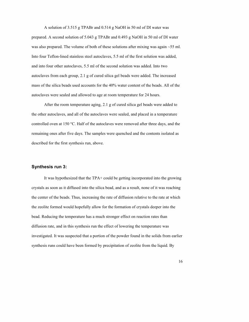
The pre-aged beads also showed a coating of crystals similar to that noted on
sample 6. The pre-aged sample made with the normal TPA+ concentration had a clean
coating with grain sizes of ~40 µm, as shown in figures 12 and 13. Sample 8, shown in
figures 14-16, had been made with the higher concentration of TPA+, showed a layer of
much smaller crystals, ~15 µm in size, with what appears to be small amounts of either
amorphous silica or very small zeolite crystals on top of the crystal layer in some places.
On sample 7, a region where the bead had been stuck to another is visible, and the same
kind of larger crystals are visible there. In figure 14, note that the thickness of the coating
layer on the beads varied significantly – the coating on the specific bead shown is thinner
than some others.
27
Figure 12: Sample 7 (Normal TPA, pre-aged), 100x. Larger crystal from interface with
other bead visible on right.
Figure 13: Sample 7, 250x. Close up of crystalline coating.

28
Figure 14: Sample 8 (High TPA, pre-aged), 100x. Note how much smoother the surface of the coating
is.
Figure 15: Sample 8, 250x. Even at 250x, most of the surface appears smooth.

29
Figure 16: Sample 8, 500x. Small crystal grains finally visible. Note the presence of something
covering them in some areas.
Synthesis run 3:
The solids from the 7 and 10 day samples were intact, opaque, and did not have
the same sort of crystalline coating as the original synthesis runs. The beads had a
physical strength consistent with the unconverted silica gel, and there was only a very
thin coating. When cleaved, the outermost layer of the beads was an opaque white, while
the inside was transparent. This suggests that the interior of the bead was largely
unaltered. There was no powder observed in these samples; the beads stuck together only
slightly. As can be seen in figures 17 and 18, the beads from sample 5 (7 days, pre-aged)
have a thin coating of small crystals (~20 µm) as well as a material that did not appear to
be crystalline, somewhat similar to what was observed in sample 8 of run 2, though the
coating layer was thinner.

30
Figure 17: Run 3, Sample 5, 100x.
Figure 18: Run 3, Sample 5, 250x. Note how the crystalline layer appears to be covered by an
amorphous layer in many areas.

31
The solid samples taken at 14 days showed the same patterns as had been
observed in the earlier trials. Although the problem of the zeolite coating breaking off of
the beads was still observed, the extent of the breakage appeared to be less than observed
in the previous experiments, with significantly less powder formed. Most of the
unconverted portions of the beads, after removal of the zeolite coating, appeared to
constitute 40-75% of the volume of the bead, with higher conversion observed in the pre-
aged sample. In figures 19-21, it can be seen that the outside of the coating layer in
sample 7 is composed of small crystals, comparable in size to those seen in the 7 day
sample. Also like the earlier sample, in many areas the crystalline coating appeared to
have a thin layer of something non-crystalline on top of it. Areas where the bead had
been stuck to other beads exposed the inside layer of the coating, where larger crystals
were present. These are visible in figures 22-23.

32
Figure 19: Run 3, sample 7 (14 day, pre-aged), 100x
Figure 20: Run 3, sample 7, 250x, showing the layer of crystals.

33
Figure 21: Run 3, sample 7, 500x.
Figure 22: Run 3, sample 7, 100x. Showing inside of coating layer, from a location where another
bead had been stuck to.

34
Figure 23: Run 3, sample 7, 250x. Close up of the inside of coating layer.
The solid samples taken at 18 days showed much greater conversion. As in the 14
day sample, and all the samples from the previous two synthesis runs, the beads were
stuck to each other and the liner of the autoclave, and the process of removing them
caused the pieces of crystalline zeolite to break. In the non-pre-aged sample, most of the
beads had been almost entirely converted to the zeolite, with significant variation in the
degree of conversion between different beads within the sample. In the pre-aged sample,
there were several intact beads which, when cleaved, contained no traces of unconverted
silica visible to the naked eye. There were several intact beads of small size which had
not been completely converted, while some larger beads had been completely converted.
These completely converted beads were partially hollow, consisting of a solid crystalline
shell containing loosely bound crystalline material, with significant open space.

35
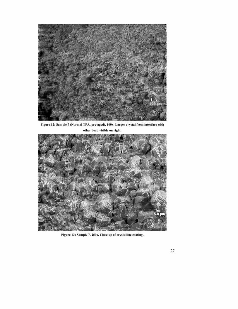
Under SEM, comparison of samples 7 and 8 (14 and 18 day, respectively),
showed remarkable differences. In figures 24-26, it can be seen that the outside of the
coating showed almost no traces of anything on top of the crystals, as had been noted
with many of the other samples. The crystals observed were also larger, indicating that
during the added synthesis time, some of the smaller crystals must have merged with the
larger ones. Comparison of figures 24-26 with figures 27-28 (pre-aged and non-pre-aged,
respectively) shows far fewer visible crystals on the non-pre-aged sample. This further
confirms that the pre-aging helps to improve crystal growth.
Figure 24: Run 3, Sample 8, 100x. Exposed layer composed entirely of crystals.
36
Figure 25: Sample 8, 250x. Close up image of crystalline surface.
Figure 26: Sample 8, 500x.

37
Figure 27: Sample 4 (18 day, non-pre-aged), 100x. Note the absence of obvious crystals on surface.
Figure 28: Run 3, sample 4, 250x. Traces of crystalinity apparent under this higher magnification.

38
Silica gel beads were completely converted into zeolite crystals in the 130 °C
process, after allowing 18 days of reaction time following a 24 hour pre-aging. These
beads produced are consistent with the goal of these experiments, in that an intact bead of
ZSM-5 zeolite has been produced from a silica gel sphere. The results of the other trials
have shed light on what factors effect the conversion of amorphous silica into zeolite
crystals, and can help guide us in improving the process
Zeolite bead structure
The fact that the zeolite beads produced through this process are hollow is not
surprising. The density of the porous amorphous silica gel is ~1.3 g/cm3 owing to the
large internal pore volume, while the density of the solid zeolite crystals is ~2.1 g/cm3,
even after accounting for the volume of the micro-pores. Because of this increase in
density, the total volume of the fully converted silica bead must be smaller than that of
that of the original bead. Indeed, a cursory inspection of the vials in which the products
were stored in showed that those allowed to react longer appeared to occupy a much
smaller volume (Though the effect of better packing of broken spheres and powder vs.
intact spheres also contributes to this).
Since the zeolite growth starts at the outer surface of the silica gel beads, the
outermost layer of the converted beads would be expected to have the same outside
diameter, and this was confirmed through observation. Thus the only way for the density
to increase is for there to be open space inside of the spheres. There are potential benefits
and downsides to this fact. The most immediate downside is that a hollow sphere will be
weaker, and less resistant to crushing and cracking than a solid one, and this could inhibit
Comment: You need to precede this with the other results that led to this
experiment. Include XRDs, photos, etc.
Comment: Photos will help here too.
39
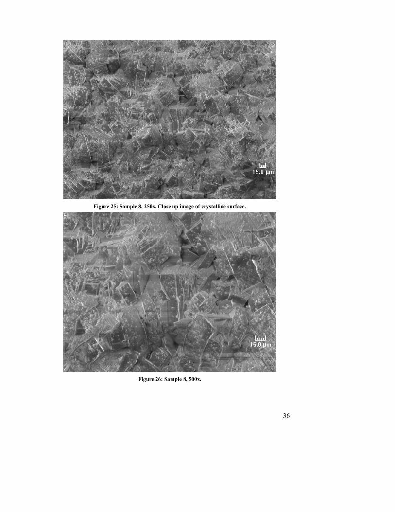
the eventual application of these beads. Ideas for strengthening the product will be
considered later. The bead structure can be seen in figures 29-31, which show the macro-
view of the beads under SEM. Figure 29 shows pieces of the outer layer for adjacent
beads, which were stuck to the main bead photographed. Also visible in the macro SEM
of some samples were holes into the sample several hundred µm in diameter which
formed during hydrothermal treatment. It is expected that in water treatment applications,
these would be beneficial by allowing improved access of the water to the inside of the
bead.
Figure 29: Run 3, Sample 7, 20x.

40
Figure 30: Run 2, sample 8, 20x. A partially removed coating layer is clearly shown here, as are
several holes that formed in the bead.

41
Figure 31: Run 3, Sample 5, 20x. As this SEM clearly shows, the beads aged for shorter lengths of
time have a far thinner coating.
In these zeolite beads, the interior was made up of loosely bound crystals of the
zeolite, with no particular structure (such as concentric spheres). These crystals were
much larger than the individual grains which made up the outer layers of the converted
beads. In water treatment applications, this would aid in mass transfer of the impurities
being absorbed from the outer layers of the zeolite bead to the center. The large amount
of open space in the beads produced through this process though is certainly in excess of
that which is necessary for efficient mass transfer in water treatment applications.
It is possible that this open space inside the beads could cause undesirable
retention of fluid, but this is unlikely to be a serious problem, because when these spheres
were cleaved after only 30 minutes of drying in air, the crystals inside appeared damp to
visual examination, but no liquid water was observed. This indicates that water diffused

42
rapidly through the outer layer, either through the micro-pores in the zeolite crystals, or
more likely through the gaps between crystals. This also suggests that if these were used
for water treatment, the outer layer would not act to block access to the internal crystals.
This aspect of the structure of these zeolite beads is not itself likely to be problematic in
water treatment applications, and is indeed very well suited for them.
Potential improvements
There are a number of issues which would need to be addressed before zeolite
beads like this would be ready for serious application however. These include the
strength of the final zeolite beads, the issue of the beads sticking to each other and the
reaction vessel, the non-uniform degree of conversion within given batches, and indeed
whether these zeolites beads actually function as well as expected in an actual treatment
system.
The problem of the beads sticking to each other appears to happen very slowly
over the course of the synthesis. In the 130 degree synthesis run, the samples allowed to
react for only 7 days exhibited very little sticking, and the final products were not at all
sticky. It thus appears that as the crystalline zeolite layer is forming on the outside of the
silica bead, it simply grows together with the crystalline layer forming on adjacent beads.
The obvious solution to this would be to use some form of gentle agitation, so that two
beads are never sitting stationary against each other for long enough for them to attach to
each other. The agitation would most likely consist of simply rotating the autoclave
during the hydrothermal treatment, as on a rotisserie, for example. This would also serve
to prevent any of the beads from sticking to the sides of the reaction vessel.

43
Care would need to be taken that such agitation was not so rough that it resulted
in damage to the beads during the synthesis process. Crushing or fracturing resulting
from the agitation is not the particular mechanism of damage that is of prime concern
here – if the beads were exhibiting that sort of damage during the synthesis process they
would be too fragile for large-scale use anyway. Damage by abrasion is more worrisome,
due to the duration of the synthesis process. It would thus be appropriate to use only the
minimum level of agitation necessary to prevent aggregates from forming.
The problem of the non-uniform conversion among different beads within the
same batch is another problem that ought to be addressed before it could be applied on a
scale larger than proof of concept. Because it was observed that the size of the initial
silica bead was not a completely accurate predictor of the conversion of that bead (that is,
if the size of the converted bead is the same as or proportional to the initial size of the
bead, which there is no reason to question), there must be some difference in either the
environment of the different beads during the hydrothermal treatment, or the composition
or microstructure of the silica gel beads used.
The most likely cause of the non-uniform conversion of the beads is differences in
the environment during the hydrothermal treatment. It is unlikely that there were any
temperature differences within the individual autoclaves which would persist long
enough to affect the zeolite formation, since they were in an environment of nearly
constant temperature, and the reaction is so slow that its contributions to temperature
would be infinitesimal.
Differences in concentrations of reagents and the availability of reagents from the
solution however were definitely present. The beads were resting at the bottom of the

44
autoclave, with about 1 inch of liquid above them. It is possible that the synthesis mixture
near the bottom of the autoclave was partially depleted of the reagents, and this would
have inhibited conversion of the beads there. Beads which were situated next to the edges
or in the corners at the bottom of the autoclave had less surface area available for mass
transport of the reagents into the bead, and this also could have slowed their conversion.
All of these problems would be solved by gentle agitation, which would have the
additional benefits described above for preventing the beads from sticking to each other.
It is entirely possible that maintaining mixing of the solution during the synthesis process
could reduce the time required for the synthesis, which is currently long enough to be
cumbersome.
If there are still problems with non-uniform conversion even with agitation, the
problem might be partially caused by non-uniform composition or properties of the silica
gel beads. It has been reported that small differences in the silica source can have
significant effects on the crystallization rate [2]. It was immediately noted that the silica
gel beads supplied were not all of uniform composition. There were a number of
discolored beads (less than 1%) present in the silica gel beads as supplied. These were
manually removed from the beads before use in these experiments, but their presence
suggests that the silica gel beads used were not produced to a high standard of purity and
consistency – they were intended for use as a desiccant, where this is not as important.
Whether there are other variations in the composition and/or properties of the silica gel
which are not obvious on visual inspection would require additional analysis, and
possibly investigation of alternate suppliers.

45
Finally, if the problems of non-uniform conversion could not be remedied by
these means, the process could simply be run for a longer time, or the inclusion of small
pieces of amorphous silica in the final product could be accepted. A small amount of
amorphous silica still present would not have any detrimental effect on the performance
except that it would not function as zeolite. It might even provide some measure of
increased structural strength.
The strength of the final zeolite beads will probably be an issue using this process
without modification. Cleaving or crushing zeolite beads required little force, and if they
were used in an industrial scale packed column, there would be a significant likelihood
that the zeolite beads would be damaged. In a laboratory scale, however, the strength
would definitely be sufficient for a proof of concept. A related question about strength is
how the process of calcination would change the physical properties of these zeolite
beads. Calcination was not performed in any of these experiments, and calcining the
samples could have a positive or negative effect on the strength of the beads.
Assuming that laboratory tests demonstrated the effectiveness of these zeolite
beads for water treatment, improvements in the physical strength of the beads would be
justified. One possible area of solutions to this would be custom manufacture of the silica
gel used as a starting material, to incorporate some sort of structural reinforcement that
would remain intact after the hydrothermal treatment. Some sort of durable fiber could be
incorporated into the silica gel before it is formed into beads, and would remain in the
structure of the beads after they were converted into zeolite, so the final beads would be a
composite of zeolite reinforced by some fiber. Such a fiber would have to be chosen such
that it would not interfere with the growth of the zeolites or their final application.

46
Alternately some material with a rigid structure could be incorporated into the gel, which
would serve to give added structural reinforcement.
Adding materials to the silica gel is undesirable, as it would not be economical
except on a large scale, and it takes up space in the bead that could be composed of active
zeolitic material. It might be possible to add some sort of chemical treatment, perhaps
some sort of polymer, which could serve to strengthen the bead, but this would pose all of
the same problems as forming pellets from zeolite particles and a binder.
Optimization of the basic process might offer some degree of enhanced strength.
As noted previously, in the experiments in the second synthesis run it was discovered that
changing the concentration of TPA+ in the synthesis mixture resulted in changes in the
size of the grains of zeolite crystals. This could affect the strength of the resulting zeolite
beads. Also the pH of the synthesis mixture could be investigated as a means of adjusting
the physical properties of the zeolite beads.
Finally, even if these measures are found to be either impractical or produce
insufficient gains in strength, the entire issue might be worked around by packaging the
zeolite beads in a “cartridge”, a container which would be of an appropriate shape, and
which the water to be treated could be pumped through. A column consisting of a stack
of such cartridges could be filled with less physical shock applied to the beads, and would
not place the weight of all the packing upon the beads at the bottom of the column. Such
technology is already used in many applications, including home water treatment.
Comment: Results. Show us.

47
Conclusions:
Within this project, porous, amorphous silica gel beads have been converted into
beads composed entirely of crystalline silicalite zeolite, specifically ZSM-5, which has
shown promise for water treatment applications. During the course of this project, a
synthesis procedure has been developed, and the initial, largely ineffective process
refined to one capable of producing completely converted, intact, zeolite beads.
The best conversion of silica gel beads to zeolites was obtained after 18 day
hydrothermal treatment at 130° C. In order to achieve maximum conversion, it was
necessary to pre-age the zeolite beads in the synthesis mixture, at room temperature,
before beginning hydrothermal treatments. The synthesis mixture used contained TPABr
and NaOH in a ratio of 1.05:1. The ratio of NaOH to Silica used was 1:20. No agitation
was used, and it is believed that this resulted in several issues, and that gentle agitation
would produce better results

48
Future Work:
As has been discussed above, there are many potential areas for future work to
expand on this work. These could include implementing some of the possible remedies
for problems discussed, or to improve the economy of the process. Future research work
could center on the application of these zeolite beads in water treatment, or in other areas,
such as catalysis (as was described in the Exxon patent).
It has been reported that a great many different structure directing agents have
been reported to direct formation of ZSM-5, and some researchers have been able to
synthesize ZSM-5 without any organic structure directing agent [2]. The reports of fully-
inorganic synthesis of ZSM-5 have not been examined in the course of this project, and
the applicability of those methods is unknown. If they were found effective in this
application, they would provide a significant cost savings. This is an important area of
research, especially after the water treatment applications of zeolite beads of this type
have been demonstrated. If the cost of the process could be brought low enough that it
was affordable for widespread use, it could take the place of activated charcoal filters in
not only industrial-scale applications, but in home use, where the zeolite would be
packaged in some sort of disposable cartridge.
Although the physical properties of the zeolite beads right after fabrication are
important, in order to be useful, they must maintain these properties for a useful lifetime
in their final application. After becoming saturated with contaminates adsorbed from the
water being purified, the zeolites must be regenerated in some way. One scheme of doing
this is to incorporate some sort of catalyst into the zeolite structure, and expose the zeolite
beads to an appropriate environment so that the adsorbed contaminates would be broken

49
down on the spot. The preparation of iron-containing zeolites was mentioned in the
background section, however the procedure used for that is very different from the one
used to produce these zeolite beads. Including such catalysts in the zeolite beads could
affect the durability, growth, or adsorption efficiency of the beads and it is likely that
such developments would require significant changes to the process.
The issue of long-term stability is also always present and would be of key
interest to research into the application of these zeolite beads. Questions that would have
to be addressed include: Will the beads degrade excessively during regeneration? Are
there other contaminates present in the water streams to be treated that could be adsorbed
and resist regeneration? Are there contaminates in the water streams that would directly
attack the zeolites, or render them ineffective by forming solid deposits (ex: hard water)?
The process developed here is still in need of significant further refinement, but
the principle of the process has been demonstrated. Future work could investigate how
this process could be improved, through use of various means of agitation, and fine-
tuning the reaction conditions (concentrations of reagents, temperature, and reaction
time). Research and experimentation to investigate the differences between various types
of silica gel for the purpose of conversion to zeolite beads could also provide information
useful for optimizing the production of zeolite beads from such silica gel.
There are ripe opportunities for research also on the application of these zeolite
spheres in water treatment, now that a ready means to produce them has been developed.
Confirmation of the effectiveness of ZSM-5 zeolite beads at removing impurities from
water would justify and encourage future work with zeolite beads fabricated in this

50
manner or through some other means. If water treatment applications can be confirmed,
that also opens up the door to combining the zeolite beads with a regeneration catalyst.
Even if, for some unexpected reason, zeolite beads of this sort are not useful in
water treatment, continued research with these is not necessarily in vain. Beads made
from other zeolites might find application for highly efficient and/or selective removal of
impurities from process streams within the chemical industry, or in catalysis applications,
in which zeolites and other forms of zeolite pellet (such as the ones described in the
Exxon patent) have been frequently used. The principle and methods that could be
developed to integrate regeneration catalysts into zeolite beads could also be applied to
making a zeolite-supported catalyst for any other type of catalysis application
All of these possibilities for further research are well within current capabilities,
and might make appropriate topics for future MQP work at WPI. I believe that there is a
strong potential for beads of zeolites like these, in a variety of applications. The one-shot
nature of this synthesis method makes it easier to implement than the multi-step methods
that have been used to produce zeolite pellets. This project has proved that this simpler
process is entirely viable, and I hope that it acts as a foundation and inspiration for future
work in this area.

51
References: 1. US Patent Application 20010002426 (2002) Mohr, Gary David and Janssen, Marcel Johannes
Gerardus, Assinged to Exxon Research and Engineering Co. Hydrocarbon conversion process
using a zeolite bound zeolite catalyst.
2. Szostak, Rosemarie. Molecular Sieves Principles of Synthesis and Identification. New York: Van Nostrand Reinhold, 1989.
3. Gonthier, Sylvie, Robert W. Thompson. "Effects of Seeding on Zeolite Crystalization and the Growth Behavior of Seeds."Advanced Zeolite Science and Applications. 1994.
4. Lai, Zhiping, et al. "Microstructural Optimization ofa Zeolite Membrane for Organic Vapor Separation." Science 300(2003): 456-460.
5. Hsu, Cheng-Ye, Anthony S. T. Chiang, Rosilda Selvin, and Robert W. Thompson. "Rapid Synthesis of Zeolite Nanocrystals." Journal of Physical Chemistry. (2005):
6. Ayse, Erdem-Senatalar, et al. "Adsorption of Methyl Tertiary Butyl Ether on Hydrophobic." Environmental Engineering Science 24(2004): 722-729.
7. Szostak, Rosemarie, Vinayan Nair, Tudor L. Thomas. "Incorporation and Stability of Iron in." Journal of
Chemical Society 83(1987): 487-494.

52
Appendix I: Experimental Notes
Synthesis Run 1:
Synthesis started at 2:35pm on 12/8
Sample Silica used (g) Solution used (ml) Removal time
1 1.506 5.4 12/9, 3:47 pm
2 1.538 5.6 12/10, 4:48 pm
3 1.499 5.5 12/11, 12:35 pm
4 1.492 5.4 12/11, 5:27 pm
5 1.513 5.5 12/12, 1:25 pm
Synthesis Run 2:
Synthesis started at 4:12 pm on 2/23
Sample Silica used (g) Solution used (ml) Pre-age High TPA Duration
1 2.119 5.8 No No
2 2.084 5.8 No Yes
3 2.102 5.6 Yes No
4 2.105 5.7 Yes Yes
3 days
5 2.095 5.6 No No
6 2.095 5.9 No Yes
7 2.092 5.6 Yes No
8 2.088 5.9 Yes Yes
5 days
Synthesis Run 3:
Synthesis started at 4:55 pm on 3/23
Sample Silica used (g) Solution used (ml) Pre-age Duration
1 2.016 5.6 No 7 Days
2 2.027 5.6 No 10 Days
3 2.008 5.5 No 14 Days
4 1.993 5.9 No 18 Days
5 2.007 5.6 Yes 7 Days
6 2.001 5.7 Yes 10 Days
7 2.015 5.5 Yes 14 Days
8 2.013 5.6 Yes 18 Days