preparatory survey report on the project ...open_jicareport.jica.go.jp/pdf/12067229_01.pdfii plant...
TRANSCRIPT
ILD
JR
12-040
PREPARATORY SURVEY REPORT ON
THE PROJECT FOR
EMERGENCY REPAIR AND
OVERHAUL WORKS FOR
THE JEBBA HYDRO POWER STATION
IN
THE FEDERAL REPUBLIC OF NIGERIA
MARCH 2012
JAPAN INTERNATIONAL COOPERATION AGENCY (JICA)
YACHIYO ENGINEERING CO., LTD.
Federal Ministry of Power (FMP) Jebba Hydro Electric Plc. (JHEP) The Federal Republic of Nigeria

PREFACE
Japan International Cooperation Agency (JICA) decided to conduct the
preparatory survey to Yachiyo Engineering Co., Ltd.
The survey team held a series of discussions with the officials concerned of the
Government of the Federal Republic of Nigeria, and conducted field investigations. As
a result of further studies in Japan, the present report was finalized.
I hope that this report will contribute to the promotion of the project and to the
enhancement of friendly relations between our two countries.
Finally, I wish to express my sincere appreciation to the officials concerned of the
Government of Nigeria for their close cooperation extended to the survey team.
March, 2012
Kyoko KUWAJIMA
Director General,
Industrial Development and Public Policy Department
Japan International Cooperation Agency

i
Summary ① Outline of the Country
The Federal Republic of Nigeria (hereafter referred to as Nigeria), facing onto the Gulf of Guinea in
the central part of Western Africa, covers an area of 924,000 square kilometers, has a population of
approximately 140 million (2007, according to the National Bureau of Statistics, Nigeria) and is one
of the world’s biggest producers of petroleum. Its national land area is approximately 2.5 times the
size of Japan and is divided into the semi-arid north, which has a Sub-Saharan climate, and the
marshy south that is partitioned by the Benue River and Niger River. In terms of cultural background
too, the country is divided into the northern and southern halves with distinct living styles in each.
Nigeria holds the largest reserves of petroleum and natural gas in Africa; in 2010 it produced 2.15
million barrels per day, and crude oil and natural gas accounted for approximately 75 percent of total
export value that year. The per capita GNI of Nigeria is US$1,180 (2011, World Bank), and the
Human Development Index is 0.295 (United Nations Development Plan, 2011), making Nigeria 186th
out of 187 countries.
② Background of the Project
The main power stations of Nigeria were constructed during the period from the middle of the 1960s
to the latter part of the 1980s, however, facilities are badly deteriorated, they cannot undergo overhaul
due to insufficient spare supply capacity and there is a lack of spare parts and engineers. As a result,
power shortages occur all over the country. Currently, approximately 65 percent of the generating
facilities owned by the Power Holding Company of Nigeria (PHCN) have been in use beyond the
statutory service life (15 years) and are in need of urgent upgrading. Due to the lack of maintenance
of generating facilities and suspension of new investments due to the economic stagnation of Nigeria,
deterioration of PHCN-owned generating facilities is advancing and major power outages are
frequently occurring in even urban centers. Accordingly, many enterprises and large-scale users
operate their own private generators. In order to address the deterioration of generating facilities, the
Government of Nigeria had plans to rapidly promote the introduction of IPPs and boost generating
equipment capacity to 10,000 MW by December 2010, however, it has been slow putting these plans
into effect and the issue of power shortages has still not been resolved. The peak demand for power in
Nigeria is growing every year and the demand for power has recently reached approximately 6,800
MW. Meanwhile, although the total plant capacity of existing thermal and hydropower generating
facilities is given as 6,600 MW, actual output in July 2010 is 3,825 MW due to deterioration of
equipment at hydropower dams, thus creating an absolute shortage in supply capacity.
Jebba Hydro Power Station, which is operated by Jebba Hydro Electric Plc. (JHEP) under the
jurisdiction of PHCN, utilizes the hydroelectric energy of the Niger River and is equipped with six
water turbine and generator units possessing rated plant capacity of 578.4 MW. The plant was
completed in 1985. Together with Kainji Hydro Power Station and Siroro Hydropower Station, this

ii
plant has helped shoulder the burden of power supply in Nigeria. However, plant output is greatly
restricted at present because the Unit 4 and 6 generators suffered major damage as a result of a
lightning-induced failure in April 2009. The Nigeria side has tendered repairs for Unit 6 through its
own funding and the necessary work is currently being implemented. Against such a background, the
Government of Nigeria issued a request to the Government of Japan seeking the urgent rehabilitation
of the Unit 4 generator (96.4 MW, vertical axis propeller turbine) at Jebba Hydro Power Station.
Based on the request, the Government of Japan consigned JICA to implement the preliminary survey
from January 17 to February 2, 2011, in which it ascertained the contents of the request and verified
its appropriateness. Based on the survey findings, the governments of the two countries signed the
Exchange of Notes (E/N) on April 11, 2011, while JICA and the Government of Nigeria signed the
Grant Agreement (G/A) on May 17 the same year.
③ Outline of the Study findings and contents of the Project
Based on the above preliminary survey, the Government of Japan decided to implement the
preparatory survey (the survey) and JICA dispatched the survey team to Nigeria from July 27 to
August 19, 2011 in order to confirm the contents of the request and discuss the implementation
contents with the Nigeria officials, conduct field investigation of the Project site and collect related
materials. After returning to Japan, based on the materials collected in the field, the team examined
the necessity, appropriateness and social and economic effects and so on of the Project and compiled
the findings into the draft report on the preparatory survey. JICA dispatched the study team to explain
the draft report on the preparatory survey from January 18 to January 27, 2012, and the team
explained and discussed the draft report with the Nigeria side and reached a basic agreement with the
Government of Nigeria.
In the survey, based on the findings of the preliminary survey, rough design and cost estimation were
carried out on the necessary and optimum contents and scale to realize the achievements described
within the framework of the concluded E/N and G/A. In addition, examination was conduced on the
contents of the Nigerian scope of works, implementation plan and important points in operation and
maintenance for achieving the Project goals such as restoring generation capacity of Unit 4 and so on.
In particular, concerning the scope of the assistance, the contents of the request were prioritized via
field survey, etc. upon conducting evaluation of the technical appropriateness based on the thinking
described in the table below.
Table Contents of Rehabilitation Equipment, Instruments and Parts for Unit 4 Generator
Item Contents
Restoration of parts broken by the accident of 2009
Renew the insulation of the stators and rotor coils. Specifically, through replacing the coil that carries current in the generator rotor and stator, renew the coil insulation that experiences temperature increase following use and degradation over an extended period. Since current flow through conducting wire generally tends to slow down when temperature increases, replacing insulated parts makes it possible to reduce temperature
iii
and improve safety and efficiency. Such repair work is referred to as insulation renewal. Moreover, through replacing the parts that connects coils to coils and securing balance, it is possible to minimize vibration and achieve smooth and stable rotation.
Overhaul in line with deterioration over time
Replace the parts (thrust bearings and air cooler, etc.) that can only be replaced when the generator undergoes disassembly.
Equipment improvement
Also conduct parts replacements (sensors, etc.) related to equipment improvement over the extend that is possible.
As a result, basic agreement was reached with the Nigerian side concerning the following general
contents of assistance
1) Stator core and associated parts
2) Stator coil and associated parts
3) Rotor pole
4) Rotor rim support modification parts
5) Repair parts and instruments
6) Current transformer for measuring instruments
7) Site work
④ Project implementation schedule and project cost estimation
The supervising government agency on the Nigerian side is the Federal Ministry of Power (FMOP),
and the implementing agency is JHEP. It is estimated that approximately 21.5 months will be
required as the equipment procurement lead-time from signing of the procurement agent agreement to
installation. Moreover, the expenses to be borne by the Nigerian side are is estimated to be 106
million yen if the project implemented.
⑤ Project evaluation
It is anticipated that Project implementation will bring about the following effects.
- Appropriateness
The Project will contribute to the realization of Nigeria’s development plans that emphasize
increased production of power, i.e. the 7 Point Agenda that was indicated in 2007 and the
National Energy Policy. Also, since it will impart benefits to the general public including
impoverished people, it is deemed to have high relevance as the Japanese Grant Aid Scheme
undertaking. In terms of benefiting population, as a result of Project implementation, it will be
possible to supply stable power to approximately 140 million residents of Nigeria. As the Project
will lead to improvement of electric power equipment and enhancement of the peak generating
output, it will help alleviate the problems at times of peak power, make it possible to extend
utilization times and thereby contribute to improvement of citizen lifestyles and economic
iv
development. Because power interruptions and voltage drop will be mitigated when operating
x-ray and other medical instruments in hospitals and using power tools in industrial plants, it will
become possible to use such instruments and tools for longer times, thereby making a
contribution to economic development. The Unit 4 generator, which is targeted for improvement
in the Project, is a large-scale unit made by a Japanese maker and possessing rated output of 96.4
MW. Since Nigeria has no makers capable of making a generator of similar scale, and the unit
targeted for rehabilitation in the Project was made in Japan, there is deemed to be necessity and
technical advantage in having a Japanese enterprise implement the Project work. Because the
repair of Unit 4, which is having to operate in a damaged state, is an urgent requirement and
expected to benefit the citizens of Nigeria including people living in poverty, it is deemed to be
appropriate for implementation under the grant aid scheme of the Government of Japan.
- Effectiveness
The following effects are anticipated as a result of Project implementation.
(1) Quantitative effects
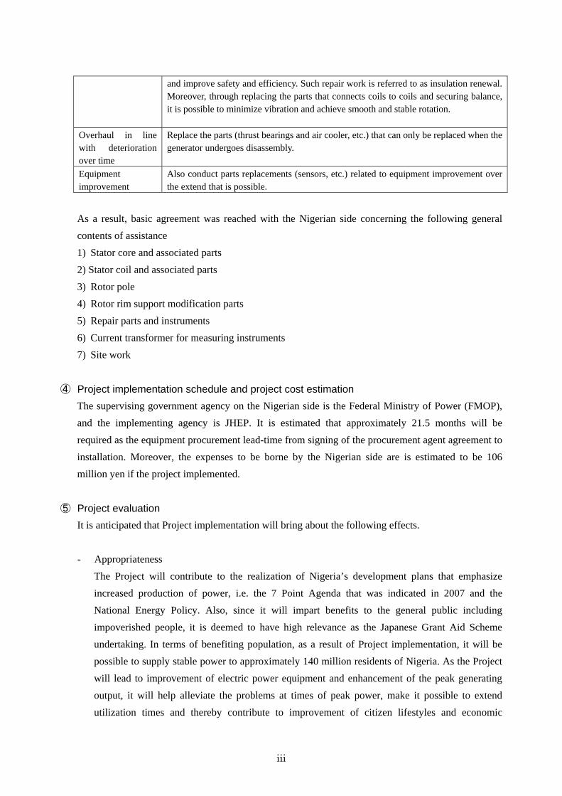
1) Maximum output
Due to vibrations and such problems, Unit 4 is currently unable to generate sufficient even if water
intake is increased from the dam. Because the Project will result in the renewal of meters needed in
order to monitor temperature, etc. in coils, thrust bearings, coolers and other devices, it will become
possible to safely secure output and the maintenance load will be mitigated. Concerning the reference
value, output in 2010 has been adopted as the value for during and after 2009 when the accident
occurred.
Indicator Reference Value (2010) Target Value (2016)
Maximum output (MW) 45.9 MW (47.6%) 96.4 MW (100%)
2) Available electric energy
Through replacing main parts such as rotor coils, stator coils and thrust bearings and so on in
Unit 4, vibrations during operation will be reduced and it will be possible to provide stable
power supply. In other words, setting the annual generated amount of power of Unit 4 as the
quantitative indicator, the goal is to restore stable power supply based on rehabilitation aiming
to attain an average value of this generated amount equivalent to the value prior to the accident
in 2009. Specifically, the goal shall be to achieve an average amount of power generation in
three years after Project completion equivalent to the mean value of power generation in the 10
years prior to the accident. (The appendices indicate movements in the generated amount of
power at Jebba Hydropower Station).

v
Indicator Reference Value (mean
value from 1999 to 2008)
Target Value (mean amount of generated
power over 3 years from 2014)
Available electric energy (GWh/year)
226 GWh/year 226 GWh/year
3) Frequency of major accidents
Operation of Unit 4 was suspended for three months as a result of the accident in 2009. It is
currently barely operating but could be stopped by a vibration-caused accident again. In the case
where repairs are conducted, it is anticipated that emergency stoppages lasting one month or more
will be reduced to zero.
Indicator Reference Value (2010) Target Value (2013)
Frequency of major accidents (entailing stoppage of 1 month or longer)
1 0
4) Greenhouse gas emission reductions
When calculated based on the available electric energy in paragraph 2) above, the reduced amount of
emissions of greenhouse gases will be as follows.
Electric energy contributing to
emissions reduction
(GWh/year)
Baseline emissions
(tCO2/year)
Project emissions
(tCO2/year)
Leakage (tCO2/year)
Total emissions reduction
(tCO2/year)
No.4 Generator 226 191,000 0 0 191,000
(2) Qualitative effects (Project overall)
Current Conditions and Problems Project Measures
(target works) Project Effects and Improvements
In Nigeria, power interruptions frequently occur due to deterioration and overload of power generation facilities, and these are impeding the development of local industries.
Repair of the generator meters and display lamps, etc.
Repair of the dial thermometer and so on will make it possible to manage temperature, conduct stable operation and prevent accidents. As a result, stable power supply will be realized, thereby enabling local manufacturing and industries to be vitalized.
In Nigeria, power interruptions frequently occur due to deterioration and overload of power transmission and distribution facilities, and these are impeding the stable operation of medical care agencies.
Repair of the generator coils and metal, etc.
Repair of the coils and metal will reduce vibrations and stabilize the power waveform of the generator. As a result, stable power supply will be provided to hospitals and universities, and contribution will be made to the stable operation and vitalization of such medical and educational facilities and enhancement of services for residents.

vi
Current Conditions and Problems Project Measures
(target works) Project Effects and Improvements
In Nigeria, power interruptions frequently occur due to deterioration and overload of power generation facilities, and these are adversely affecting the living environment of local residents.
Repair of the generator
Through the provision of stable power supply, the living environment of citizens in Nigeria will be improved.
Jebba Hydropower Station is incurring increasing maintenance costs due to frequently occurring failures and part replacements, and this is placing a burden on JHEP finances.
Repair of the generator
Upgrading of instruments in the hydropower station will lead to less frequent parts replacements and thus allow maintenance costs to be reduced.

Contents
Preface
Summary
Contents
Location Map / Perspective
List of Figures & Tables
Abbreviations
Chapter 1 Background of the Project ............................................................................................ 1-1
1-1 Background of the Assistance .............................................................................................. 1-1
1-2 Outline of the Project ........................................................................................................... 1-1
1-3 Handling of Motoring Failure .............................................................................................. 1-6
1-4 Environmental and Social Consideration ............................................................................. 1-7
1-4-1 Environmental Impact Assessment ............................................................................... 1-7
1-4-2 Anticipated Impacts of Project Implementation ........................................................... 1-7
1-4-3 Areas using Asbestos .................................................................................................... 1-7
1-4-4 Environmental Regulations in Nigeria concerning Asbestos ....................................... 1-8
1-4-5 Treatment of Wastes ..................................................................................................... 1-8
1-4-6 Safety Measures during Works ..................................................................................... 1-9
1-4-7 Other Points .................................................................................................................. 1-9
Chapter 2 Contents of the Project ................................................................................................. 2-1
2-1 Basic Concept of the Project ................................................................................................ 2-1
2-2 Outline Design of Japanese Assistance ................................................................................ 2-1
2-2-1 Design Policy ............................................................................................................... 2-1
2-2-1-1 Basic Policy .............................................................................................................. 2-1
2-2-1-2 Policies regarding Natural Conditions ...................................................................... 2-1
2-2-1-3 Policies regarding Social and Economic Considerations ......................................... 2-2
2-2-1-4 Policy regarding Utilization of Local Enterprises .................................................... 2-2
2-2-1-5 Policies regarding Operation and Maintenance ........................................................ 2-2
2-2-1-6 Policies regarding Procurement Scope and Technical Level of Equipment ............. 2-3
2-2-1-7 Policies regarding Construction/Procurement Methods and Construction Period ... 2-3
2-2-2 Basic Plan (Construction Plan / Equipment Plan) ........................................................ 2-4
2-2-2-1 Overall Plan .............................................................................................................. 2-4
2-2-2-2 Design Policy ........................................................................................................... 2-5
2-2-2-3 Configuration of Equipment ..................................................................................... 2-5
2-2-2-4 Equipment Plan ........................................................................................................ 2-7
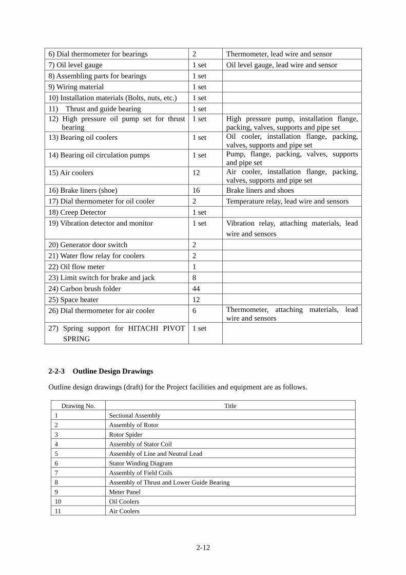
2-2-3 Outline Design Drawings ........................................................................................... 2-12
2-2-4 Implementation Plan ................................................................................................... 2-24
2-2-4-1 Implementation Policy............................................................................................ 2-24
2-2-4-2 Implementation Condition ...................................................................................... 2-25
2-2-4-3 Scope of Works ....................................................................................................... 2-26
2-2-4-4 Consultant Supervision ........................................................................................... 2-27

2-2-4-5 Quality Control Plan ............................................................................................... 2-30
2-2-4-6 Procurement Plan ................................................................................................... 2-30
2-2-4-7 Operation Guidance Plan ........................................................................................ 2-30
2-2-4-8 Implementation Schedule ....................................................................................... 2-30
2-3 Obligations of Recipient Country ....................................................................................... 2-31
2-4 Project Operation Plan ........................................................................................................ 2-32
2-4-1 Basic Concept ............................................................................................................. 2-32
2-4-2 Operation and Maintenance Setup .............................................................................. 2-33
2-4-3 Periodic Inspection Items ........................................................................................... 2-33
2-4-3-1 Periodic Inspection of Water Turbine Generator .................................................... 2-33
2-4-4 Spare Parts Purchasing Plan ....................................................................................... 2-36
2-4-4-1 Categories of Spare Parts........................................................................................ 2-36
2-4-4-2 Spare Parts Target Equipment and Purchasing Plan ............................................... 2-36
2-4-4-3 Budget Steps for Spare Parts .................................................................................. 2-37
2-4-4-4 Test Apparatus and Maintenance Tools .................................................................. 2-37
2-5 Project Cost Estimate ......................................................................................................... 2-38
2-5-1 Initial Cost Estimation ................................................................................................ 2-38
2-5-2 Operation and Maintenance Costs .............................................................................. 2-39
Chapter 3 Project Evaluation ........................................................................................................ 3-1
3-1 Preconditions ........................................................................................................................ 3-1
3-1-1 Preconditions for Project Implementation .................................................................... 3-1
3-1-2 Preconditions and External Conditions for Achieving the Overall Project Plan .......... 3-1
3-2 Necessary Inputs by Recipient Country ............................................................................... 3-1
3-3 Important Assumptions ......................................................................................................... 3-2
3-4 Project Evaluation ................................................................................................................ 3-3
3-4-1 Relevance ..................................................................................................................... 3-3
3-4-2 Effectiveness................................................................................................................. 3-4
Appendices
1. Member List of the Study Team
2. Study Schedule
3. List of Parties Concerned in the Recipient Country
4. Minutes of Discussions
5. Soft Component (Technical Assistance) Plan
6. Other Relevant DATA
7. Environmental Checklist
8. Monitoring Form
9. Total Output of JHPS and Average Output of the Unit
10. Jebba hydroelectric Power Station 578,400KW
11. Federal Republic of Nigeria Official Gazette
12. Reduction of Greenhouse Gas
13. Tools and Equipment for Site Work

Location Map
Jebba Hydro Power Station
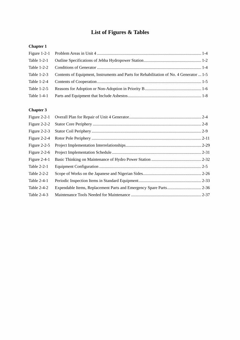
List of Figures & Tables
Chapter 1
Figure 1-2-1 Problem Areas in Unit 4 .................................................................................................. 1-4
Table 1-2-1 Outline Specifications of Jebba Hydropower Station ...................................................... 1-2
Table 1-2-2 Conditions of Generator .................................................................................................. 1-4
Table 1-2-3 Contents of Equipment, Instruments and Parts for Rehabilitation of No. 4 Generator ... 1-5
Table 1-2-4 Contents of Cooperation .................................................................................................. 1-5
Table 1-2-5 Reasons for Adoption or Non-Adoption in Priority B ..................................................... 1-6
Table 1-4-1 Parts and Equipment that Include Asbestos ..................................................................... 1-8
Chapter 3
Figure 2-2-1 Overall Plan for Repair of Unit 4 Generator.................................................................... 2-4
Figure 2-2-2 Stator Core Periphery ...................................................................................................... 2-8
Figure 2-2-3 Stator Coil Periphery ....................................................................................................... 2-9
Figure 2-2-4 Rotor Pole Periphery ....................................................................................................... 2-11
Figure 2-2-5 Project Implementation Interrelationships ....................................................................... 2-29
Figure 2-2-6 Project Implementation Schedule .................................................................................... 2-31
Figure 2-4-1 Basic Thinking on Maintenance of Hydro Power Station ............................................... 2-32
Table 2-2-1 Equipment Configuration ................................................................................................ 2-5
Table 2-2-2 Scope of Works on the Japanese and Nigerian Sides ....................................................... 2-26
Table 2-4-1 Periodic Inspection Items in Standard Equipment ........................................................... 2-33
Table 2-4-2 Expendable Items, Replacement Parts and Emergency Spare Parts ................................ 2-36
Table 2-4-3 Maintenance Tools Needed for Maintenance .................................................................. 2-37
Abbreviations
A/A Agent Agreement
A/P Authorization to Pay
AC Alternate Current
AFREN African Rural Electrification Network
ASEAN Association of Southeast Asian Nations
CDF Comprehensive Development Framework
CEO Chief Executive Officer
DAC Development Assistance Committee
DC Direct Current
ECN Energy Commission of Nigeria
EIAJ Electronic Industries Association of Japan
E/N Exchange of Notes
FMOP Federal Ministry of Power
G/A Grant Agreement
GSM Global System for Mobil Communication
IEC International Electrotechnical Commission
IPP Independent Power Plant
ISO International Organization for Standardization
JCS Japanese Electrical Wire and Cable Maker's Association Standards
JEC Japanese Electrotechnical Committee
JEM Standards of Japan Electrical Manufacturer’s Association
JICA Japan International Cooperation Agency
JIS Japanese Industrial Standards
JHEP Jebba Hydro Electric Plc.,
KEPCO Korea Electric Power Corporation
NAPTIN National Power Training Institute of Nigeria
NBET Nigeria Bulk Energy Trader
NCC National Control Center
NEEDS National Empowerment Economic Development Strategy
NEPA National Electricity Power Authority
NGO Non-Governmental Organizations
NITEL Nigeria Telecommunications Plc
NIPP National Integrated Power Project
O&M Operation and Maintenance
OJT On the Job Training
OPEC Organization of the Petroleum Exporting Countries
PHCN Power Holding Company of Nigeria
PRSP Poverty Reduction Strategy Paper
REB Rural Electrical Board

RTD Resistance Temperature Detector
UNDP United Nations Development Programme
USAID United States Agency for International Development
VAT Value-Added Tax

CHAPTER 1
BACKGROUND OF THE PROJECT

1-1
Chapter 1 Background of the Project
1-1 Background of the Assistance
The Federal Republic of Nigeria (hereafter referred to as Nigeria), located in the central part of
Western Africa next to Guinea and possessing a population of roughly 140 million (2007, according to
the National Bureau of Statistics, Nigeria), is one of the world’s biggest producers of petroleum.
Nigeria is also a multiethnic country possessing more than 250 ethnic groups and 500 languages. Its
national land area is approximately 2.5 times the size of Japan and is divided into the semi-arid north,
which has a Sub-Saharan climate, and the marshy south that is partitioned by the Benue River and
Niger River. In terms of cultural background too, the country is divided into the northern and southern
halves with distinct living styles in each.
Nigeria previously struggled with an accumulated debt burden of around US$40 billion due to
inefficient fiscal management by past military administrations, however, reforms by the civil
administration of President Obasanjo, who came to power in 1999, earned international praise, and the
Paris Club nations agreed to reduce Nigeria’s debt of US$30 billion by 60 percent at the summit that
was held in October 2005. When President Obasanjo’s term of office came to an end in 2007, Umaru
Yar’Adua was elected as the new president, however, he passed away in May 2010 and was
subsequently replaced by his vice president Goodluck Jonathan. The administration of President
Jonathan inherited the 7-Point Agenda of his predecessor and is tackling reform. Peak power demand
in Nigeria is increasing every year and the power demand has reached approximately 6,800 MW
recently, however, the actual capacity as of July 2010 is 3,825 MW due to the failure of plans to boost
generating facilities and the deterioration of existing facilities. As a result, there is an absolute shortage
of power supply.
Against such a background, the Government of Nigeria issued an urgent request to the Government of
Japan seeking rehabilitation of the Unit 4 generator (96.4 MW, vertical axis propeller turbine) at Jebba
Hydro Power Station in order to improve conditions at the station. Based on the request, the
Government of Japan consigned JICA to implement the first preparatory survey from January 17 to
February 2, 2011, in which it ascertained the contents of the request and verified the appropriateness of
assistance. Based on the survey findings, the governments of the two countries signed the E/N on April
11, 2011, while JICA and the Government of Japan signed the G/A on May 17 the same year.
1-2 Outline of the Project
Unit 4, which is the target for the request for urgent rehabilitation, has been operating at approximately
half its maximum capacity due to damage of the generator coils following lightning induced failure of
the circuit breaker in April 2009. In the preliminary survey that was implemented in January 2011, the
necessity and appropriateness of the request as a target for grant aid assistance were confirmed.
In the survey, based on the findings of the preliminary survey, rough design and cost estimation were
carried out on the necessary and optimum contents and scale to realize the achievements described
within the framework of the concluded E/N and G/A. In addition, examination was conduced on the
contents of the Nigerian scope of works, implementation plan and important points in operation and
maintenance for achieving the Project goals such as restoring generation capacity of Unit 4 and so on.
In particular, concerning the scope of the assistance, the technical appropriateness of the requested

1-2
contents was evaluated and the contents were prioritized. As a result, agreement was eventually
reached with the Nigerian side concerning the following general contents:
1) Stator core and associated parts
2) Stator coil and associated parts
3) Rotor pole
4) Rotor rim support modification parts
5) Repair parts and instruments
6) Current transformer for measuring instruments
7) Site work
Jebba Hydro Power Station, which utilizes the Jebba Reservoir (storage capacity 1 billion cubic
meters) constructed on Niger River, which runs through the west of Nigeria, was completed and
commenced operation in 1985, and it comprises six water turbine and generator units. Kainji Hydro
Power Station (760 MW) is situated further upstream on the same river, and Jebba utilizes the water
discharged from here to generate power. Effective head is 27.6 meters and the rated plant capacity is
578.4 MW (96.4 MW/unit x 6 units). Table 1-2-1 shows the outline specifications.
Table 1-2-1 Outline Specifications of Jebba Hydropower Station
Item / Contents
Unit No.
Unit 1
(2G-1)
Unit 2
(2G-2)
Unit 3
(2G-3)
Unit 4
(2G-4)
Unit 5
(2G-5)
Unit 6
(2G-6)
1. Water turbine Fixed Blade Propeller Single Runner
(1) Maker Escher Wyss/Vatech/ANDRIZ, Austria
(2) Turbine Blade (number of
blades) 5 blades (blade diameter: 7,100 mm)
(3) Guide Vane(Wicket Gate) 24
(4) Effective head (m) Min.25.0 m~Max.29.7m
(5) Effective flow (m3/sec) 376 m3/sec.
(6) Effective water level during
operation (m) 103.0~93.0m
(7) Maximum output (MW) 96.4MW (Output at Max. Rated Head: 102.7 MW)
(8) Rotations (rpm) 93.75 rpm, Runner Away Speed: 179rpm
2. Generator Type : Synchronous (Commissioning Year 1985)
(1) Maker HITACHI, Japan
(2) Output (MVA/MW) 103.5MVA/96.4MW
(3) Rotations / rotating direction 93.75 rpm/clockwise direction
(4) Cooling method Air Cooling: 12 Air Coolers/One Generator
(5) Power factor 0.85
(6) Voltage (kV), current (A) 16,000V/3,735A
(7) Frequency (Hz) 50 Hz
(8) Poles 64
(9) Applicable standard ANSI C50.12 (1965)
3. Auxiliary equipment
(1) Control system Analog local control (each unit)
(2) Main transformer 16/330kV、119MVA×6
1-3
Item / Contents
Unit No.
Unit 1
(2G-1)
Unit 2
(2G-2)
Unit 3
(2G-3)
Unit 4
(2G-4)
Unit 5
(2G-5)
Unit 6
(2G-6)
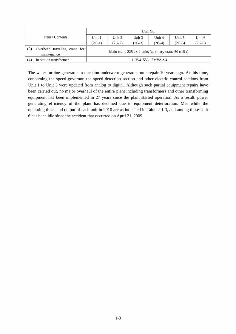
(3) Overhead traveling crane for
maintenance Main crane 225 t x 2 units (auxiliary crane 50 t/15 t)
(4) In-station transformer 11kV/415V、2MVA×4
The water turbine generator in question underwent generator rotor repair 10 years ago. At this time,
concerning the speed governor, the speed detection section and other electric control sections from
Unit 1 to Unit 3 were updated from analog to digital. Although such partial equipment repairs have
been carried out, no major overhaul of the entire plant including transformers and other transforming
equipment has been implemented in 27 years since the plant started operation. As a result, power
generating efficiency of the plant has declined due to equipment deterioration. Meanwhile the
operating times and output of each unit in 2010 are as indicated in Table 2-1-3, and among these Unit
6 has been idle since the accident that occurred on April 21, 2009.
1-4
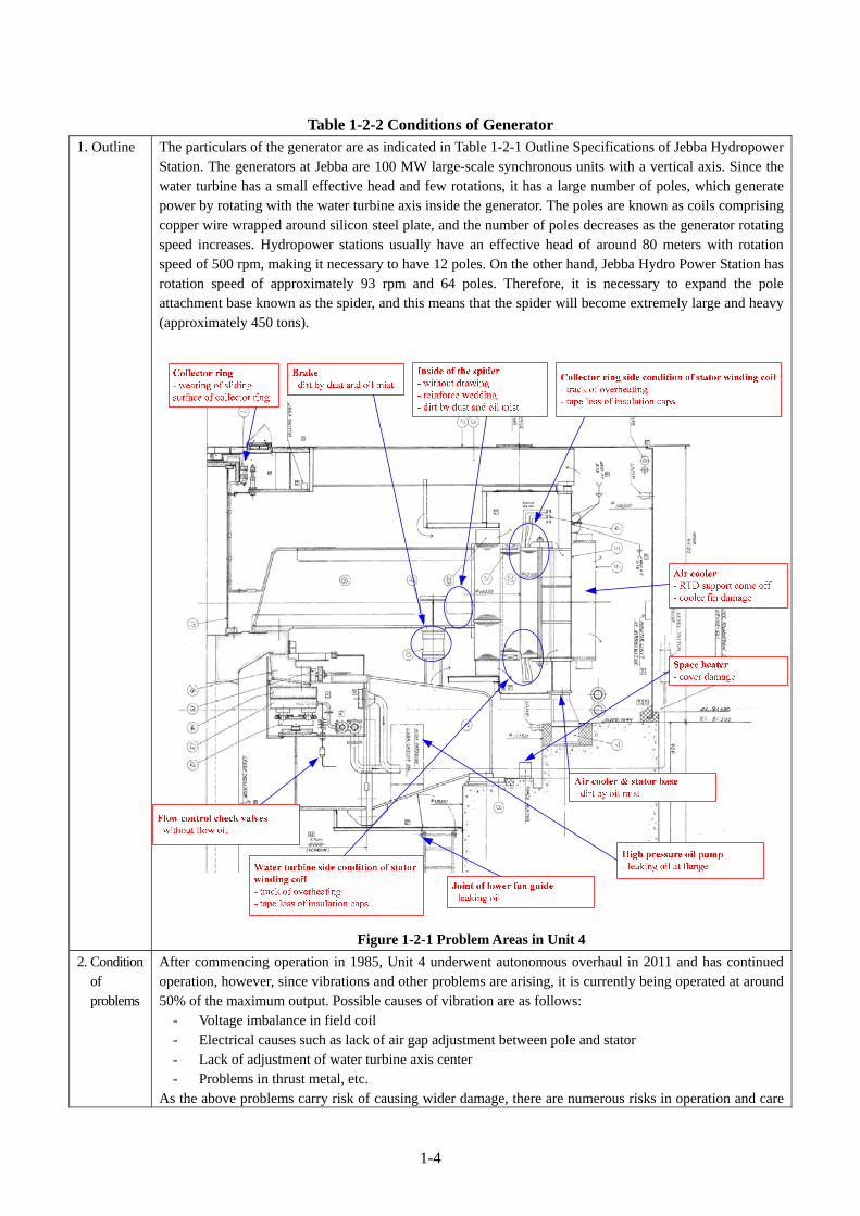
Table 1-2-2 Conditions of Generator 1. Outline The particulars of the generator are as indicated in Table 1-2-1 Outline Specifications of Jebba Hydropower
Station. The generators at Jebba are 100 MW large-scale synchronous units with a vertical axis. Since the water turbine has a small effective head and few rotations, it has a large number of poles, which generate power by rotating with the water turbine axis inside the generator. The poles are known as coils comprising copper wire wrapped around silicon steel plate, and the number of poles decreases as the generator rotating speed increases. Hydropower stations usually have an effective head of around 80 meters with rotation speed of 500 rpm, making it necessary to have 12 poles. On the other hand, Jebba Hydro Power Station has rotation speed of approximately 93 rpm and 64 poles. Therefore, it is necessary to expand the pole attachment base known as the spider, and this means that the spider will become extremely large and heavy (approximately 450 tons).
Figure 1-2-1 Problem Areas in Unit 4
2. Condition of problems
After commencing operation in 1985, Unit 4 underwent autonomous overhaul in 2011 and has continued operation, however, since vibrations and other problems are arising, it is currently being operated at around 50% of the maximum output. Possible causes of vibration are as follows:
- Voltage imbalance in field coil - Electrical causes such as lack of air gap adjustment between pole and stator - Lack of adjustment of water turbine axis center - Problems in thrust metal, etc.
As the above problems carry risk of causing wider damage, there are numerous risks in operation and care

1-5
will be required from now on. Regarding the causes of failures, in addition to those arising from deterioration after 30 years of use, the following causes are involved.
(1) Autonomous replacement of rotors During the rotor spider repairs conducted in 2001, since problems were found in the thrust metal, the Unit 4 rotor was attached to the Unit 5 generator. After that, work on the Unit 4 generator was suspended due to lack of funds. As a result, following emergency repair of the Unit 5 generator spider, the Unit 4 stator was installed. The Unit 4 generator suffered further major damage in 2009 when motoring occurred. At this time, adjustment of the assigned voltage and so on was insufficient, leading to electrical imbalance and impeding the operation.
(2) Motoring As a result of motoring-induced coil heating brought about by grounding of station wiring in 2009, degradation occurred in insulation materials and this led to insulation failure. Figure 1-2-1 shows the concrete problem areas in detail, while photographs are shown in the annex.
In view of the above conditions, concerning the scope of the assistance, upon evaluating the technical
validity of the requested contents, it was decided to conduct a field investigation and attach an order of
priority to the requested contents. At this time, examination was conducted bearing in mind the scope
indicated in Table 1-2-3.
Table 1-2-3 Contents of Equipment, Instruments and Parts for Rehabilitation of No. 4 Generator Item Contents
Restoration of parts broken by the accident of 2009
Renew the insulation of the stators and rotor coils. Specifically, through replacing the coil that carries current in the generator rotor and stator, renew the coil insulation that experiences temperature increase following use and degradation over an extended period. Since current flow through conducting wire generally tends to slow down when temperature increases, replacing insulated parts makes it possible to reduce temperature and improve safety and efficiency. Such repair work is referred to as insulation renewal. Moreover, through replacing the parts that connects coils to coils and securing balance, it is possible to minimize vibration and achieve smooth and stable rotation.
Overhaul in line with deterioration over time
Replace the parts (thrust bearings and air cooler, etc.) that can only be replaced when the generator undergoes disassembly.
Equipment improvement
Also conduct parts replacements (sensors, etc.) related to equipment improvement over the extend that is possible. Specifically, stable operation can be achieved through repairing the thrust metal and so on required for continuing operation at the same time as conducting insulation renewal of the coils that require the output recovery described above.
As a result of conducting analysis in Japan, the contents of the Project have been decided as shown in
Table 1-2-4.
Table 1-2-4 Scope of the Cooperation Originally Requested Plan Plant following Analysis in Japan (Draft) Qty
(1) Stator Core and associated parts (core stacking kit)
1. Stator Core and associated parts 1 set
(2) Stator Coil and associated parts (stator rewinding kit)
2. Stator Coil and associated parts
1 set

1-6
Originally Requested Plan Plant following Analysis in Japan (Draft) Qty
(3) Rotor Pole with field coil 3. Rotor Pole with field coil 1 set
(4) Rotor Rim support modification kit with tools 4. Rotor Rim support modification 1 set
(5) Lifting devises and sling wires (Not adopted)
(6) Replacement parts and instruments 5. Replacement parts and instruments (without rebabbitting thrust and guide bearings) (modification kit)
1 set
(7) Tools and equipment for site work (Not adopted)
(8) Current transformer 6. Current transformer 1 set
(9) Generator circuit breaker (Not adopted)
(10) Site Work 7. Site Work 1 set
Notes: Lubricating oils are not included in the above table, and are to be prepared by the Nigerian side.
Incidentally, some items were omitted from the request stage, and the reasons are indicated in Table
1-2-5.
Table 1-2-5 Reasons for Non-Adoption Item Order of Priority and Policy
Lifting devices and
tools
These tools and equipment are needed for installation works. However, because
they can be commonly used in all units and they can be procured by the local
side with its own funding, they are omitted from the scope of assistance.
Generator circuit
breaker
The generator circuit breaker is currently installed in the outdoor switchyard.
The request seeks to install a new circuit breaker between the generator and
transformer due to operating problems. It is assumed that it will be installed
close to the exciting arrangement inside the power house. Since connection with
the existing circuit breaker will become complicated and the installation space is
limited, although it is not impossible to install, it has been omitted from the
Project because its installation would entail changing the interface of the control
device.
The “rebabbitting thrust and guide bearings” that were included in the remodeling parts requested by
the Nigerian side refer to the repair (recasting) of existing metal parts (bearings). In the Project,
existing metal that has worn contact surfaces will be replaced with new metal. The existing metal will
be taken to the manufacturing plant to have its surfaces regenerated with a view to securing spare parts
for use in emergencies. However, since the metal used is a special type that can only be stored for
approximately 10 years, the likelihood of metal exchange during this period is low and expensively
purchased parts could end up being scrapped without ever being used. Also, since it would be difficult
for the Nigerian side to conduct repairs, and the cost of consigning repairs to the maker (transportation
costs, etc.) would be extremely high, these parts have been omitted from the Project. Since
emergencies would be extremely infrequent and parts could be procured if the need arose, this
omission will not impact the Project.
1-3 Handling of Motoring Failure
The motoring failure of April 2009 occurred when lightning strike caused the power station power
supply to fail. The details are not clear because there is no event recorder for automatically recording
the protective relay operating conditions, circuit breaker operating information and other operating
information, however, the following facts have been confirmed:
- When the motoring occurred, the circuit breaker didn’t automatically trip.

1-7
- Following the failure, an attempt was made to manually open the Unit 4 generator circuit
breaker, however, because it was inoperable, the power station contacted the NCC and asked to
be cut off from the circuit breaker on the 330 kV substation side.
In conducting rehabilitation of Unit 4 in this grant aid project, it is important that steps are taken to
prevent a similar situation arising in future. Upon conducting survey, it has been confirmed that JHEP
has implemented the following measures in the wake of the accident. As a result, it should be possible
to appropriately cut off overcurrent caused by similar accidents in the future.
- It replaced the old pneumatic operating mechanism type Unit 4 generator circuit breaker with a
spring powered stored energy operating mechanism type circuit breaker.
- It reviewed the distribution panel circuitry for tripping the circuit breaker from the protective
relay at times of motoring.
1-4 Environmental and Social Consideration
As the Project includes the implementation of insulation renewal geared to ensuring the safe operation
of existing generators, the following environmental and social consideration issues will arise in the
works.
1-4-1 Environmental Impact Assessment
On checking with JHEP, there were found to be no particular impacts on the natural and social
environment because the roads needed for the works are already in place, the development and
utilization of hydropower resources is consistent with national policies and the Project entails repair of
a generator at Jebba Hydro Power Station that was constructed 27 years ago. Therefore, the JHEP
responded that there is no need to implement an environmental impact assessment (EIA) based on
Nigerian legislation when it comes to implementing the Project.
1-4-2 Anticipated Impacts of Project Implementation
Since the Project entails the renewal and repair of the turbine and generator and other equipment of a
hydropower station that was constructed 27 years ago, almost all the works will be conducted indoors
and the works period is less than one year, it is thought that impacts on landscape, society and
environment can be kept to a minimum. Since the Project site is located away from built-up areas
within the power station grounds, there will be no impact when vehicles come and go for the works.
Moreover, since there are security gates to access the power station, there will be extremely low risk of
entry to the Project site by third parties. Moreover, since almost all the work will be conducted indoors
and will generate only minor vibration, dust and noise, and the distance from residential areas is
sufficiently far, there will be no impacts on neighboring residents. The coils to be removed contain
asbestos, however, since this will be treated by operators according to domestic regulations, there
won’t be any problem. Moreover, since the site work will entail the replacement of generator parts
while the majority of parts manufacturing and processing will be conducted in well-equipped Japanese
plants, there will be no impact on water and air quality in the site work.
1-4-3 Areas using Asbestos
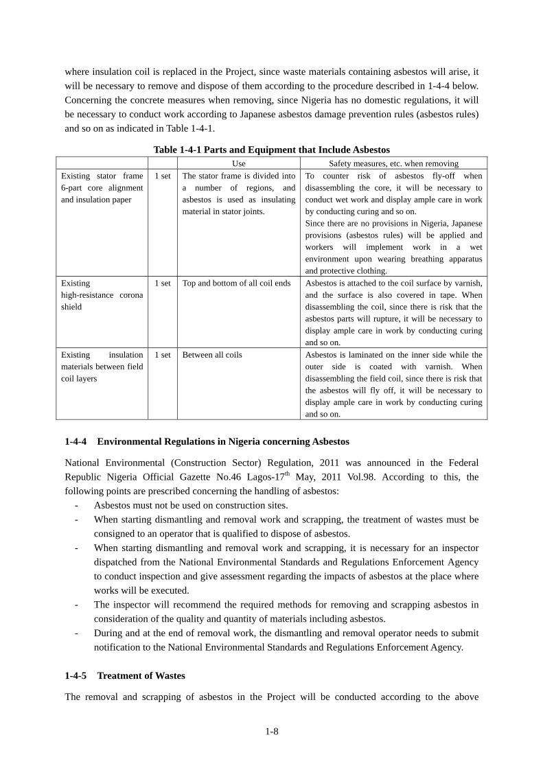
Based on the results of the field survey, Table 1-4-1 shows the parts that contain asbestos. In the event
1-8
where insulation coil is replaced in the Project, since waste materials containing asbestos will arise, it
will be necessary to remove and dispose of them according to the procedure described in 1-4-4 below.
Concerning the concrete measures when removing, since Nigeria has no domestic regulations, it will
be necessary to conduct work according to Japanese asbestos damage prevention rules (asbestos rules)
and so on as indicated in Table 1-4-1.
Table 1-4-1 Parts and Equipment that Include Asbestos Use Safety measures, etc. when removing
Existing stator frame 6-part core alignment and insulation paper
1 set The stator frame is divided into a number of regions, and asbestos is used as insulating material in stator joints.
To counter risk of asbestos fly-off when disassembling the core, it will be necessary to conduct wet work and display ample care in work by conducting curing and so on. Since there are no provisions in Nigeria, Japanese provisions (asbestos rules) will be applied and workers will implement work in a wet environment upon wearing breathing apparatus and protective clothing.
Existing high-resistance corona shield
1 set Top and bottom of all coil ends Asbestos is attached to the coil surface by varnish, and the surface is also covered in tape. When disassembling the coil, since there is risk that the asbestos parts will rupture, it will be necessary to display ample care in work by conducting curing and so on.
Existing insulation materials between field coil layers
1 set Between all coils Asbestos is laminated on the inner side while the outer side is coated with varnish. When disassembling the field coil, since there is risk that the asbestos will fly off, it will be necessary to display ample care in work by conducting curing and so on.
1-4-4 Environmental Regulations in Nigeria concerning Asbestos
National Environmental (Construction Sector) Regulation, 2011 was announced in the Federal
Republic Nigeria Official Gazette No.46 Lagos-17th May, 2011 Vol.98. According to this, the
following points are prescribed concerning the handling of asbestos:
- Asbestos must not be used on construction sites.
- When starting dismantling and removal work and scrapping, the treatment of wastes must be
consigned to an operator that is qualified to dispose of asbestos.
- When starting dismantling and removal work and scrapping, it is necessary for an inspector
dispatched from the National Environmental Standards and Regulations Enforcement Agency
to conduct inspection and give assessment regarding the impacts of asbestos at the place where
works will be executed.
- The inspector will recommend the required methods for removing and scrapping asbestos in
consideration of the quality and quantity of materials including asbestos.
- During and at the end of removal work, the dismantling and removal operator needs to submit
notification to the National Environmental Standards and Regulations Enforcement Agency.
1-4-5 Treatment of Wastes
The removal and scrapping of asbestos in the Project will be conducted according to the above

1-9
guidelines, however, because the existing generator coils are the state assets of Nigeria, it is
appropriate that the Nigerian side carry out their scrapping.
The environmental checklist and monitoring form for the Project are indicated in the appendices. The
monitoring form indicates the items that need to be adhered to by the implementing agency and works
contractor when removing and scrapping the asbestos. The Nigerian side will need to conduct
monitoring according to this form and report the results to JICA.
1-4-6 Safety Measures during Works
Concerning work that entails handling materials including asbestos, it will be necessary to take
measures to secure the safety of operators. Specifically, when conducting similar work in Japan, it will
be necessary to at least adhere to the contents of Level 3 according to applicable Japanese legislation
(asbestos regulations), and this will entail making operators wear breathing apparatus and protective
clothing and work in a wet environment as indicated in Table 2-2-2. When conducting asbestos
removal work, it will be necessary to comply with Nigerian regulations while adopting safe
procedures and methods in reference to Japanese rules.
1-4-7 Other Points
Through limiting use of fossil fuels through conducting repair of equipment at a hydropower station,
the Project will assist climate change mitigation measures in a developing country.

CHAPTER 2
CONTENTS OF THE PROJECT
2-1
Chapter 2 Contents of the Project
2-1 Basic Concept of the Project
Against a background of advancing national development, the peak demand for power in the Federal
Republic of Nigeria has reached approximately 6,800 MW. Meanwhile, although the total plant
capacity of existing generating facilities is given as 6,600 MW (with thermal power accounting for 70
percent and hydropower for 30 percent), actual output in July 2010 is 3,825 MW due to the failure to
strengthen generating facilities and deterioration of equipment at hydropower dams, thus creating an
absolute shortage in supply capacity.
Existing hydropower stations in Nigeria comprise Kainji Hydro Power Station7 (rated output: 760
MW) and Jebba Hydro Power Station (rated output: 540 MW, operated by Jebba Hydro Electric Plc.
(JHEP) on the Niger River, and Siroro Hydropower Station (rated output: 600 MW) on a tributary of
the Niger; however, these power facilities are unable to provide an ample supply of power due to
long-term stoppages arising from generator breakdowns and water level adjustments, etc.
2-2 Outline Design of Japanese Assistance
2-2-1 Design Policy
2-2-1-1 Basic Policy
The basic policy is to repair the Unit 4 generator of Jebba Hydro Power Station in order to alleviate the
stretched power supply situation in Nigeria. Specifically, the design will be compiled based on the
basic policies of repairing the regions damaged in the accident of 2009, conducting replacement
(overhaul) of parts that have become degraded over time and improving equipment.
2-2-1-2 Policies regarding Natural Conditions
(1) Design in consideration of temperature and humidity
Although the atmospheric temperature in the area around Jebba Hydro Power Station is high
at 30°C to 40°C throughout the year, considering Jebba Hydro Power Station’s long
experience of plant operation over 27 years, it will not be necessary to consider heat from the
generator due to recovery in output because parts procured under the Project will be furnished
to a generation unit located in the powerhouse. Also, the Project does not require procurement
of precision instruments/parts which need to be kept away from high temperature and high
humidity.
(2) Design in consideration of rainfall
High rainfall is observed from May to October, however, the highest rainfall is limited to July
and August. Since the deterioration of road condition is presumed on the roads connecting to
Jebba Hydro Power Station, it is desirable to make a procurement schedule of equipment,
7 A loan of 1.5 billion yen was given by the Overseas Economic Cooperatio Fund (OECF) in 1972, and a further 2.5 billion yen was loaned in 1974.

2-2
devices and parts avoiding the said period as much as possible; however, it will be necessary
to compile a transportation plan with ample time to spare. Having said that, as most of the
installation work will be implemented inside the powerhouse, it is not necessary to consider
the effects of rain when compiling the schedule for installation of the equipment, devices and
parts procured under the Project.
2-2-1-3 Policies regarding Social and Economic Considerations
As the Project site is situated far from town of Jebba and there are security gates to access the power
station, thus, the Project will have negligible impact on third parties. Also, there will be no influence
on neighboring residents because noise generated by the power station is small and the distance from
residential areas is far enough.
Because roughly half of the people in Nigeria are Christians and the other half are Muslims, the staffs
of Jebba Hydro Power Station similarly believe in either of the above religions. Therefore, it will be
necessary to pay respect to the respective religious festive days and national holidays when the
implementation schedule is studied.
2-2-1-4 Policy regarding Utilization of Local Enterprises
In Nigeria, there are foreign owned companies for general construction, electrical works and others.
Thus, it is relatively easy to procure labor, transportation vehicles and machinery and materials for
construction works locally. There are at least three local building firms that have worked as
subcontractors for grant aid projects in the past, and it should be possible to order work other than
activities related to generator performance to them. Also, the inland transportation of machinery and
materials from the port to Jebba Hydro Power Station can be consigned to local operators.
On the other hand, although there are some local enterprises and technicians available for handling
installation of power station machinery, materials and auxiliary units, they do not have experience of
rehabilitation works on the same scale as the Project, and highly skilled technicians are required for
the rehabilitation of machinery and materials as well as adjustment and testing in the rehabilitation
works. Hence, when such machinery and materials procured under the Project are installed, it will be
necessary to dispatch technicians from Japan and to provide management of quality and schedule and
technical guidance to the local parties.
2-2-1-5 Policies regarding Operation and Maintenance
Since the commencement of operation in 1985, Jebba Hydro Power Station has a successful work
record of operation and maintenance by its own staffs up to date, thus, technical staffs are highly
skilled and experienced. Also, since the rehabilitation of generation units through the Project is mainly
replacement and overhaul of existing materials, machinery and parts, the operation and maintenance
methods that have already been established in Jebba Hydro Power Station can be sufficiently and fully
utilized. However, in view of the accident experienced in 2009, the Nigerian side will need to conduct
emergency-stop training of facilities based on various accident scenarios. Also, daily maintenance and
checking activities will be required to make sure equipment is operated correctly at all times.

2-3
2-2-1-6 Policies regarding Procurement Scope and Technical Level of Equipment
In consideration of the above-mentioned conditions and policies, the procurement scope and technical
level of machinery and parts shall be formulated based on the following basic principles.
(1) Policies regarding the scope of facilities, machinery and materials
To facilitate a technically and financially adequate outline design, through adopting standard
materials that comply with international specifications such as IEC and so on and adopting
common-use assembled parts and pole-mounted parts in power supply sections and cable
connectors, it will be possible to mitigate the load arising from maintenance of inventory parts
in the event of breakdown. In the generator repair work, types of dial thermometer, cable and
limit switch, etc. will be minimized with a view to ensuring compatibility of materials and
equipment and selecting the minimum required equipment composition, specifications and
quantities.
(2) Policies regarding technical level
Specifications of each item of equipment and instruments required for rehabilitation of the
target generation unit shall be designed in consideration of technical level of O&M Division
of Jebba Hydro Power Station, which will be the implementation body of operation and
maintenance after completion of the Project, and avoidance of complicated structure and
technical requirements.
2-2-1-7 Policies regarding Construction/Procurement Methods and Construction Period
Marine transportation shall be the main method to transport procured goods and materials from Japan
or the third country to Nigeria. Inland transportation distance is approximately 410 kilometers from
Apapa Port, Lagos to the Project site of Jebba Hydro Power Station. Since the transportation distance
is long as such and roughly one-quarter of the transportation road is in poor condition, it will be
necessary to pay extra attention regarding the curing and packing of equipment and materials, and to
implement safe and sure procurement without causing any hindrance to traffic.
Jebba Hydro Power Station is a hydropower generation facility where the installation and
commissioning of generation units was executed by Japanese enterprise and generator manufacturer
up to completion in 1985, and currently generator parts and so forth are still provided from Japan.
Considering this situation, when the procurement schedule of goods and materials is formulated for
the Project, since there is no direct shipment from Japan to a port in Nigeria, it will be required to
trans-ship at nearby foreign ports in Korea, China or Singapore, etc. and thus approximately two
months will need to be assumed for the transportation period.
Since the contents of procurement for the Project include long lead items and short lead items, the
equipment will be transported when the short lead items are completed, and the installation schedule
will be planned to coincide with this. Concerning the long lead items such as rotor poles and so on,
these will require 10 months solely for manufacturing and approximately one year from the purchase
order to arrival at site. Therefore, as the overall implementation schedule will be influenced by these
long lead items, it will be necessary to minimize the period required for preparation of drawings, their
approval and factory inspection.

2-4
2-2-2 Basic Plan (Construction Plan / Equipment Plan)
2-2-2-1 Overall Plan
Concerning the repair of the Unit 4 generator, the Project will entail the replacement of the stator and
rotor coil used for generating power, the thrust bearings that contain the bearings for supporting the
entire weight of the water turbine generator, the pumps and valves for supplying lubricating oil to the
thrust bearings (including oil cooler for lowering the temperature of oil flowing to the cooling oil pipes
in the thrust bearings), the air cooler for lowering the temperature of the cooling water for the overall
generator, and meters such as the space heater and thermometer used for maintenance activities.
Carbon brush, etc. Spider repair Stator coil, etc.
Air Cooler
Space heater
Rotor coil, etc.
Oil lifter and flow control valve
Trust bearing
Pivot springUtilize Existing Bearing plateEquipment Pipes in thrust tank
Guide bearing
Brake shoe and limit switch
Figure 2-2-1 Overall Plan for Repair of Unit 4 Generator
2-5
2-2-2-2 Design Policy
In determining the scale and specifications for the Project, the following design conditions have been
elaborated based on the results of examination of the above mentioned policies, principles and
conditions.
(1) Proposed place of rehabilitation work
Place of rehabilitation work: Jebba Hydro Power Station existing generator unit No. 4
(2) Climate and Site Conditions
1) Designed atmospheric temperature: 40 degree Celsius (Highest)
2) Designed relative humidity: 95% (Highest: Dewfall shall not occur)
3) Site condition: Altitude (from the mean sea level): 100m
(3) Applicable Design Codes and Standards
Codes and Standards Application
(a) International Electrotechnical Commission (IEC) General electric appliances
(b) International Organisation for Standardisation (ISO) General industrial products
(c) Japanese Industrial Standards (JIS) General industrial products
(d) The Institute of Electrical Engineers of Japan, Japanese Electrotechnical Committee (JEC)
General electric appliances
(e) The Japan Electrical Manufacturers’ Association (JEM)
General electric appliances
(f) The Japan Electric Association Committee (JEAC) General electric appliances
(g) Japanese Cable Makers’ Association Standard (JCS) Electric cable
(h) Electronic Industries Association of Japan(EIAJ) General electric appliances
(i) Electric Technology Research Association General electric appliances
(j) National Electrical Manufacturers Association (NEMA)
General electric appliances
(4) Units
In principle, the international unit system (SI Unit) shall be applied.
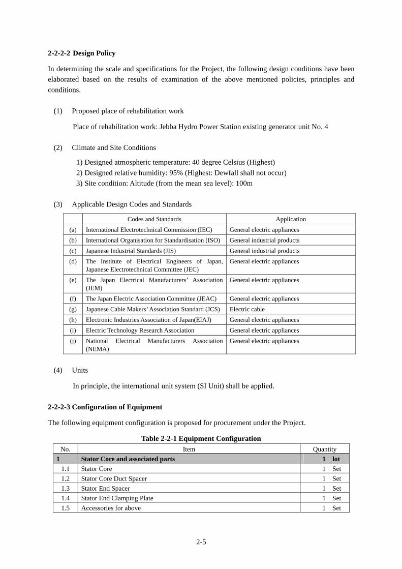
2-2-2-3 Configuration of Equipment
The following equipment configuration is proposed for procurement under the Project.
Table 2-2-1 Equipment Configuration
No. Item Quantity
1 Stator Core and associated parts 1 lot
1.1 Stator Core 1 Set
1.2 Stator Core Duct Spacer 1 Set
1.3 Stator End Spacer 1 Set
1.4 Stator End Clamping Plate 1 Set
1.5 Accessories for above 1 Set

2-6
No. Item Quantity
1.6 RTD for stator core 4 pcs
1.7 Finishing varnish for stator 1 Set
2 Stator Coil and associated parts 1 lot
2.1 Stator Coil 1008 pcs
2.2 Wedge 1 Set
2.3 Stator Coil Support Ring 1 Set
2.4 Bus lead for Inside of stator frame 1 Set
2.5 Insulation Cap 1 Set
2.6 Line and Neutral Lead 1 Set
2.7 Accessories for above 1 Set
2.8 RTD for stator coil 20 pcs
2.9 Current transformer for measuring instruments 1 Set
3 Rotor Pole with field coil 1 lot
3.1 Pole 64 pcs
3.2 Connection parts between Poles 1 Set
3.3 Pole Cotter and Liner 64 Sets
3.4 Field lead 1 Set
3.5 Finishing Varnish for Rotor 1 Set
4 Rotor Rim support modification kit 1 lot
4.1 Repair material for damaged spider 1 Set
4.2 Rotor rim keys 1 Set
4.3 Stopper for rotor rim keys 1 Set
4.4 Distance piece (Rotor rim support) 1 Set
5 Replacement Parts and Instruments 1 lot
5.1 Carbon Brush 44 pcs
5.2 Oil Deflector 1 Set
5.3 Flow Control Valve 36 pcs
5.4 RTD for Thrust Bearing Oil Temp. 1 pc
5.5 Thermal Relay for Air Cooler and Bearing 12 pcs
5.6 Dial Thermometer for Bearing 2 pcs
5.7 Oil Level Gauge 1 pc
5.8 Assembling parts for bearing 1 Set
5.9 Wiring material 1 Set
5.10 Installation materials (Bolts, nuts, etc.) 1 Set
5.11 Thrust and Guide Bearings 1 Set
5.12 High pressure oil pump set for Thrust Bearings 1 Set
5.13 Bearing oil coolers 1 Set
5.14 Bearing oil circulating pumps 1 Set
5.15 Air coolers 12 Sets
5.16 Brake Lining (shoe) 16 pcs
5.17 Dial Thermometer for Oil Cooler 2 pcs
5.18 Creep Detector 1 Set
5.19 Vibration detector and monitor 1 Set
5.20 Generator door switch 2 pcs
5.21 Water flow relay for coolers 2 pcs
5.22 Oil flow meter 1 pc
5.23 Limit switch for brake and jack 8 pcs
2-7
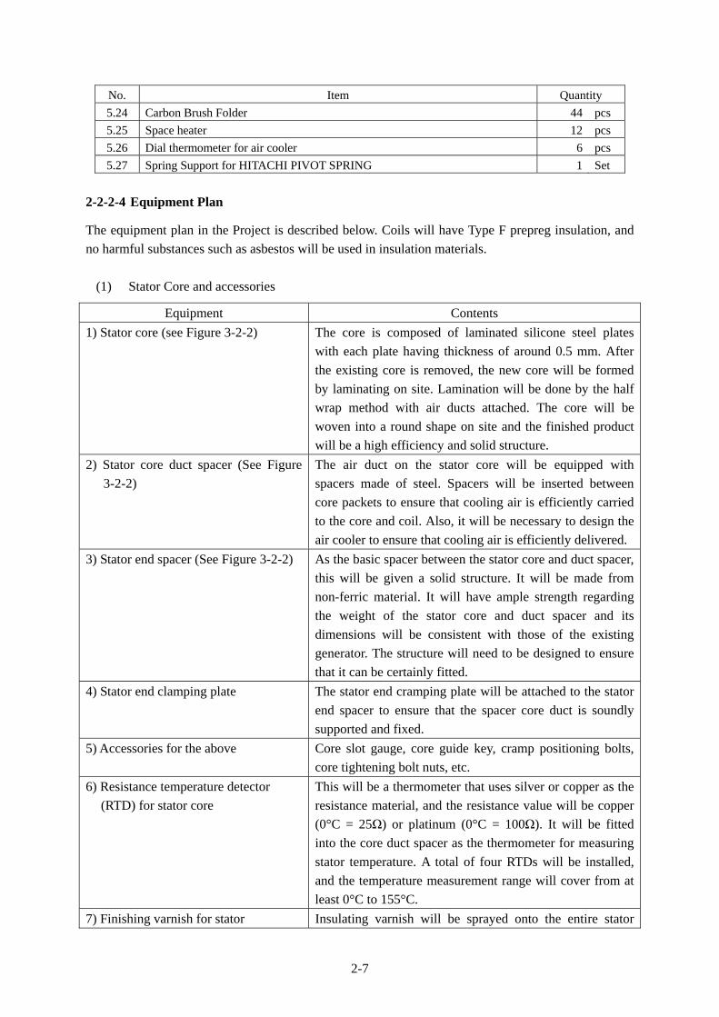
No. Item Quantity
5.24 Carbon Brush Folder 44 pcs
5.25 Space heater 12 pcs
5.26 Dial thermometer for air cooler 6 pcs
5.27 Spring Support for HITACHI PIVOT SPRING 1 Set
2-2-2-4 Equipment Plan
The equipment plan in the Project is described below. Coils will have Type F prepreg insulation, and
no harmful substances such as asbestos will be used in insulation materials.
(1) Stator Core and accessories
Equipment Contents
1) Stator core (see Figure 3-2-2)
The core is composed of laminated silicone steel plates
with each plate having thickness of around 0.5 mm. After
the existing core is removed, the new core will be formed
by laminating on site. Lamination will be done by the half
wrap method with air ducts attached. The core will be
woven into a round shape on site and the finished product
will be a high efficiency and solid structure.
2) Stator core duct spacer (See Figure
3-2-2)
The air duct on the stator core will be equipped with
spacers made of steel. Spacers will be inserted between
core packets to ensure that cooling air is efficiently carried
to the core and coil. Also, it will be necessary to design the
air cooler to ensure that cooling air is efficiently delivered.
3) Stator end spacer (See Figure 3-2-2) As the basic spacer between the stator core and duct spacer,
this will be given a solid structure. It will be made from
non-ferric material. It will have ample strength regarding
the weight of the stator core and duct spacer and its
dimensions will be consistent with those of the existing
generator. The structure will need to be designed to ensure
that it can be certainly fitted.
4) Stator end clamping plate The stator end cramping plate will be attached to the stator
end spacer to ensure that the spacer core duct is soundly
supported and fixed.
5) Accessories for the above Core slot gauge, core guide key, cramp positioning bolts,
core tightening bolt nuts, etc.
6) Resistance temperature detector
(RTD) for stator core
This will be a thermometer that uses silver or copper as the
resistance material, and the resistance value will be copper
(0°C = 25Ω) or platinum (0°C = 100Ω). It will be fitted
into the core duct spacer as the thermometer for measuring
stator temperature. A total of four RTDs will be installed,
and the temperature measurement range will cover from at
least 0°C to 155°C.
7) Finishing varnish for stator Insulating varnish will be sprayed onto the entire stator

2-8
core in order to enhance the insulation effect and prevent
rusting, dust and staining by mist oil, etc. The coating
thickness over the entire stator core will be at least 50
microns. The varnish will be the Hitachi WB101 or an
equivalent product (black color).
Figure 2-2-2 Stator Core Periphery
(2) Stator Coil and associated parts
Equipment Contents
1) Stator coil (see Figure 3-2-3) Phases: 3
Poles: 64
Slots: 504
Coils: 1,008
Connection method: 2Y
Material: Coil (copper) and insulating materials (varnish and
glass tape)
Type of insulation: B
2) Wedge Wedges will be arranged at the end of coils fitted into the
stator core in order to fix the coils to the core. The material
will be glass fiber. The wedges will have ample strength and
be composed so that coils are firmly fixed and do not detach.
3) Stator coil support ring Stator coil will be tied and fixed to the support ring with
glass tape (glass).
Material: Glass fiber
4) Bus lead for inside of stator frame There will be total six wires comprising three phases (U, V,
W) and neutral point (X, Y, Z), arranged in a circular pattern
inside the generator to enable connection at the stator coil
exit. The coil wire will comprise bus line between each phase
and neutral point.
Material: Copper
5) Insulation cap (see Figure 3-2-3) This insulation material is for protecting the treated coil end.
Stator core duct spacer
Stator end spacer
Stator flame
Stator Core

2-9
It will have a rubber cap structure with compound filled into
air gaps to secure insulation. The insulation cap will be fixed
with glass tape and serve to protect adequate insulation
performance.
Material: Rubber
6) Line and neutral lead
This is the terminal line and terminal for drawing electric
power outside of the generator, and it will be composed of
copper bars. It will comprise a structure with sufficient
strength to fix the cable.
Material: Copper
7) Accessories for the above (see
Figure 3-2-3)
Liner, insulation materials, protective tape, RTD attaching
materials
8) Resistance temperature detectors
for stator coil (see Figure 3-2-3)
These resistance temperature detectors will measure the
temperature in each coil of three phases (U, V, W) and 20
will be arranged. The arrangement will be 7 in the U phase, 7
in the V phase and 6 in the W phase.
9) Generator current transformers These measuring instrument current transformers will be
attached to the generator outlet lead in the U, V and W
phases and at the neutral point.
Figure 2-2-3 Stator Coil Periphery
Stator Core
1)
Rotor
1)
7)
5)
8)
2-10
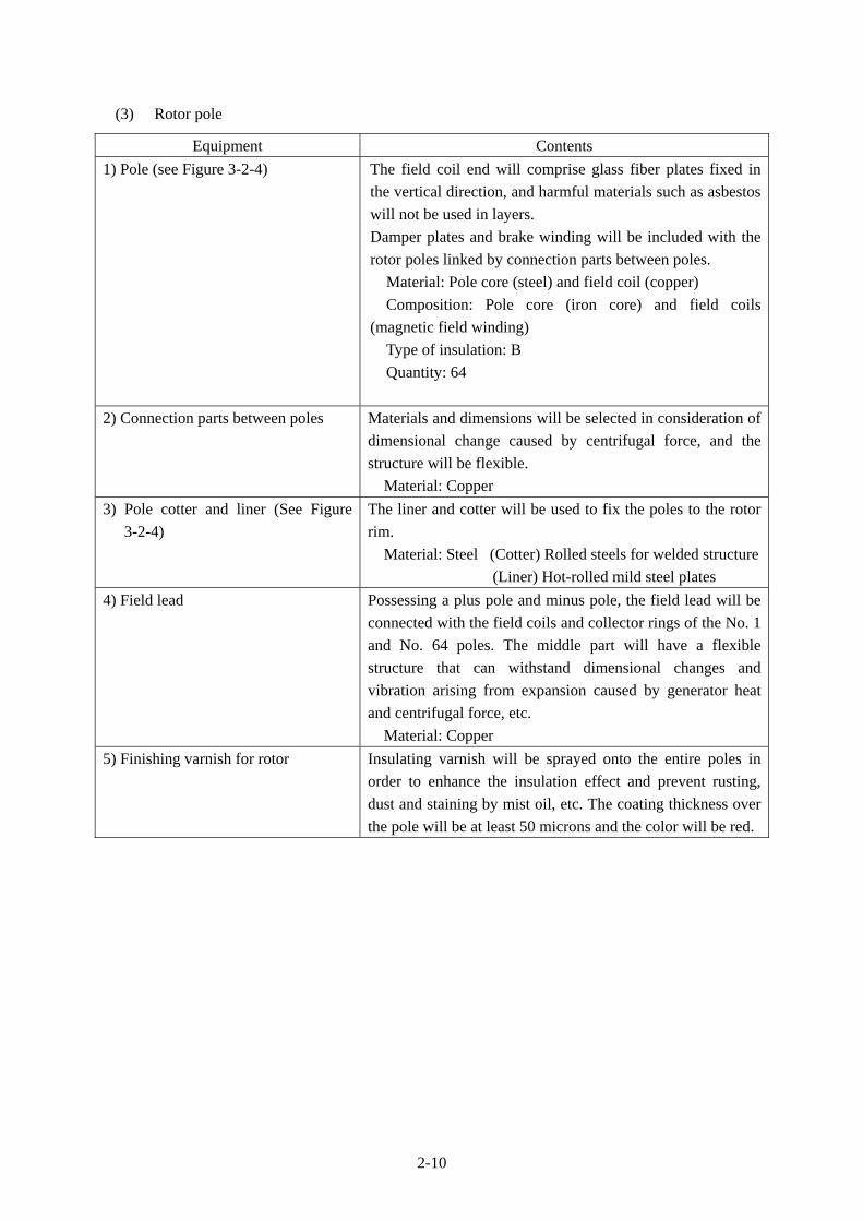
(3) Rotor pole
Equipment Contents
1) Pole (see Figure 3-2-4) The field coil end will comprise glass fiber plates fixed in
the vertical direction, and harmful materials such as asbestos
will not be used in layers.
Damper plates and brake winding will be included with the
rotor poles linked by connection parts between poles.
Material: Pole core (steel) and field coil (copper)
Composition: Pole core (iron core) and field coils
(magnetic field winding)
Type of insulation: B
Quantity: 64
2) Connection parts between poles Materials and dimensions will be selected in consideration of
dimensional change caused by centrifugal force, and the
structure will be flexible.
Material: Copper
3) Pole cotter and liner (See Figure
3-2-4)
The liner and cotter will be used to fix the poles to the rotor
rim.
Material: Steel (Cotter) Rolled steels for welded structure
(Liner) Hot-rolled mild steel plates
4) Field lead Possessing a plus pole and minus pole, the field lead will be
connected with the field coils and collector rings of the No. 1
and No. 64 poles. The middle part will have a flexible
structure that can withstand dimensional changes and
vibration arising from expansion caused by generator heat
and centrifugal force, etc.
Material: Copper
5) Finishing varnish for rotor
Insulating varnish will be sprayed onto the entire poles in
order to enhance the insulation effect and prevent rusting,
dust and staining by mist oil, etc. The coating thickness over
the pole will be at least 50 microns and the color will be red.
2-11
Figure 2-2-4 Rotor Pole Periphery
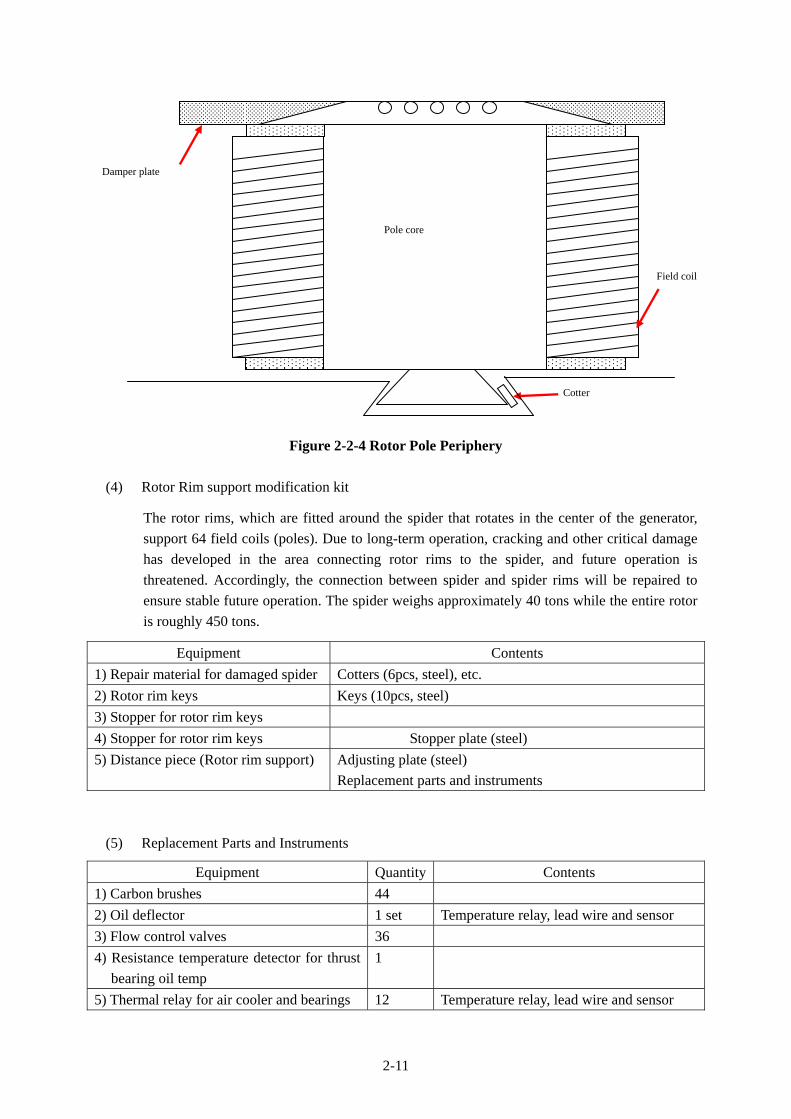
(4) Rotor Rim support modification kit
The rotor rims, which are fitted around the spider that rotates in the center of the generator,
support 64 field coils (poles). Due to long-term operation, cracking and other critical damage
has developed in the area connecting rotor rims to the spider, and future operation is
threatened. Accordingly, the connection between spider and spider rims will be repaired to
ensure stable future operation. The spider weighs approximately 40 tons while the entire rotor
is roughly 450 tons.
Equipment Contents
1) Repair material for damaged spider Cotters (6pcs, steel), etc.
2) Rotor rim keys Keys (10pcs, steel)
3) Stopper for rotor rim keys
4) Stopper for rotor rim keys Stopper plate (steel)
5) Distance piece (Rotor rim support) Adjusting plate (steel)
Replacement parts and instruments
(5) Replacement Parts and Instruments
Equipment Quantity Contents
1) Carbon brushes 44
2) Oil deflector 1 set Temperature relay, lead wire and sensor
3) Flow control valves 36
4) Resistance temperature detector for thrust
bearing oil temp
1
5) Thermal relay for air cooler and bearings 12 Temperature relay, lead wire and sensor
Damper plate
Field coil
Pole core
Cotter
2-12
6) Dial thermometer for bearings 2 Thermometer, lead wire and sensor
7) Oil level gauge 1 set Oil level gauge, lead wire and sensor
8) Assembling parts for bearings 1 set
9) Wiring material 1 set
10) Installation materials (Bolts, nuts, etc.) 1 set
11) Thrust and guide bearing 1 set 12) High pressure oil pump set for thrust
bearing 1 set High pressure pump, installation flange,
packing, valves, supports and pipe set 13) Bearing oil coolers 1 set Oil cooler, installation flange, packing,
valves, supports and pipe set 14) Bearing oil circulation pumps 1 set Pump, flange, packing, valves, supports
and pipe set 15) Air coolers 12 Air cooler, installation flange, packing,
valves, supports and pipe set 16) Brake liners (shoe) 16 Brake liners and shoes
17) Dial thermometer for oil cooler 2 Temperature relay, lead wire and sensors
18) Creep Detector 1 set
19) Vibration detector and monitor 1 set Vibration relay, attaching materials, lead
wire and sensors
20) Generator door switch 2
21) Water flow relay for coolers 2
22) Oil flow meter 1
23) Limit switch for brake and jack 8
24) Carbon brush folder 44
25) Space heater 12
26) Dial thermometer for air cooler 6 Thermometer, attaching materials, lead wire and sensors
27) Spring support for HITACHI PIVOT
SPRING
1 set
2-2-3 Outline Design Drawings
Outline design drawings (draft) for the Project facilities and equipment are as follows.
Drawing No. Title
1 Sectional Assembly
2 Assembly of Rotor
3 Rotor Spider
4 Assembly of Stator Coil
5 Assembly of Line and Neutral Lead
6 Stator Winding Diagram
7 Assembly of Field Coils
8 Assembly of Thrust and Lower Guide Bearing
9 Meter Panel
10 Oil Coolers
11 Air Coolers

APPROVEDDESIGNEDDATE CHECKED REVISION
THE PROJECT FOREMERGENCY REPAIR AND OVERHAUL WORKS FOR
THE JEBBA HYDRO POWER STATIONIN THE FEDERAL REPUBLIC OF NIGERIA
20th Feb. 2012 Ohsawa Nakagawa Tanaka
2-13
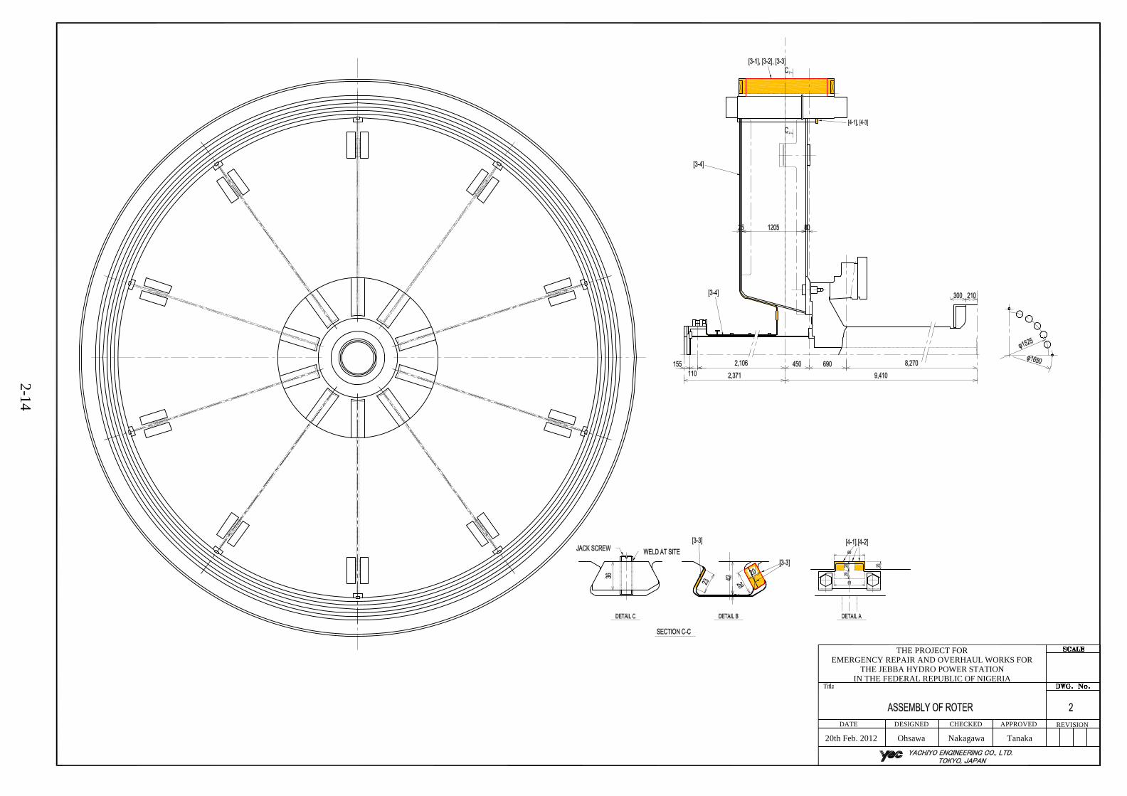
APPROVEDDESIGNEDDATE CHECKED REVISION
THE PROJECT FOREMERGENCY REPAIR AND OVERHAUL WORKS FOR
THE JEBBA HYDRO POWER STATIONIN THE FEDERAL REPUBLIC OF NIGERIA
20th Feb. 2012 Ohsawa Nakagawa Tanaka
2-14
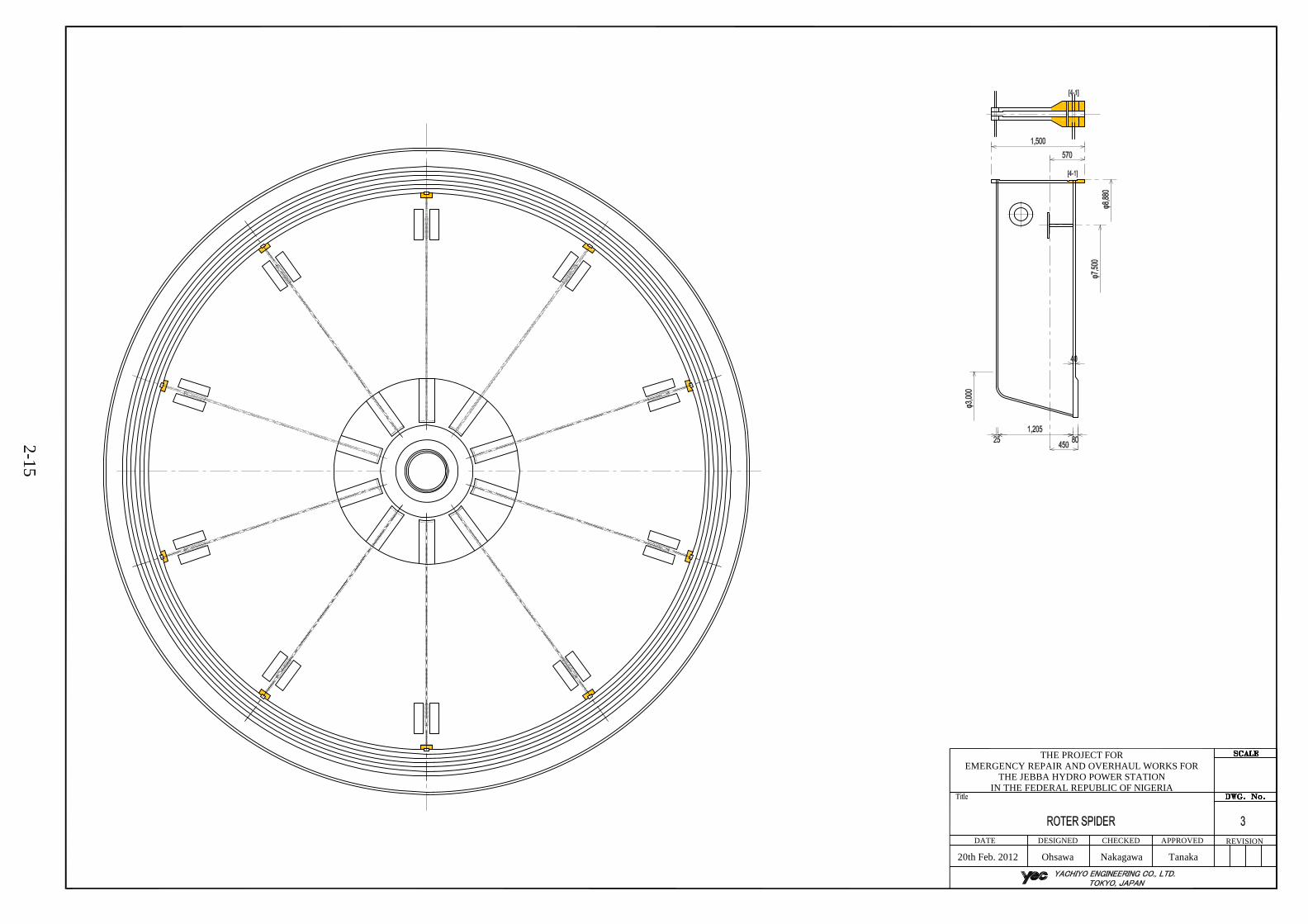
APPROVEDDESIGNEDDATE CHECKED REVISION
THE PROJECT FOREMERGENCY REPAIR AND OVERHAUL WORKS FOR
THE JEBBA HYDRO POWER STATIONIN THE FEDERAL REPUBLIC OF NIGERIA
20th Feb. 2012 Ohsawa Nakagawa Tanaka
2-15

APPROVEDDESIGNEDDATE CHECKED REVISION
THE PROJECT FOREMERGENCY REPAIR AND OVERHAUL WORKS FOR
THE JEBBA HYDRO POWER STATIONIN THE FEDERAL REPUBLIC OF NIGERIA
20th Feb. 2012 Ohsawa Nakagawa Tanaka
2-16

APPROVEDDESIGNEDDATE CHECKED REVISION
THE PROJECT FOREMERGENCY REPAIR AND OVERHAUL WORKS FOR
THE JEBBA HYDRO POWER STATIONIN THE FEDERAL REPUBLIC OF NIGERIA
20th Feb. 2012 Ohsawa Nakagawa Tanaka
2-17

APPROVEDDESIGNEDDATE CHECKED REVISION
THE PROJECT FOREMERGENCY REPAIR AND OVERHAUL WORKS FOR
THE JEBBA HYDRO POWER STATIONIN THE FEDERAL REPUBLIC OF NIGERIA
20th Feb. 2012 Ohsawa Nakagawa Tanaka
2-18

APPROVEDDESIGNEDDATE CHECKED REVISION
THE PROJECT FOREMERGENCY REPAIR AND OVERHAUL WORKS FOR
THE JEBBA HYDRO POWER STATIONIN THE FEDERAL REPUBLIC OF NIGERIA
20th Feb. 2012 Ohsawa Nakagawa Tanaka
2-19

APPROVEDDESIGNEDDATE CHECKED REVISION
THE PROJECT FOREMERGENCY REPAIR AND OVERHAUL WORKS FOR
THE JEBBA HYDRO POWER STATIONIN THE FEDERAL REPUBLIC OF NIGERIA
20th Feb. 2012 Ohsawa Nakagawa Tanaka
2-20
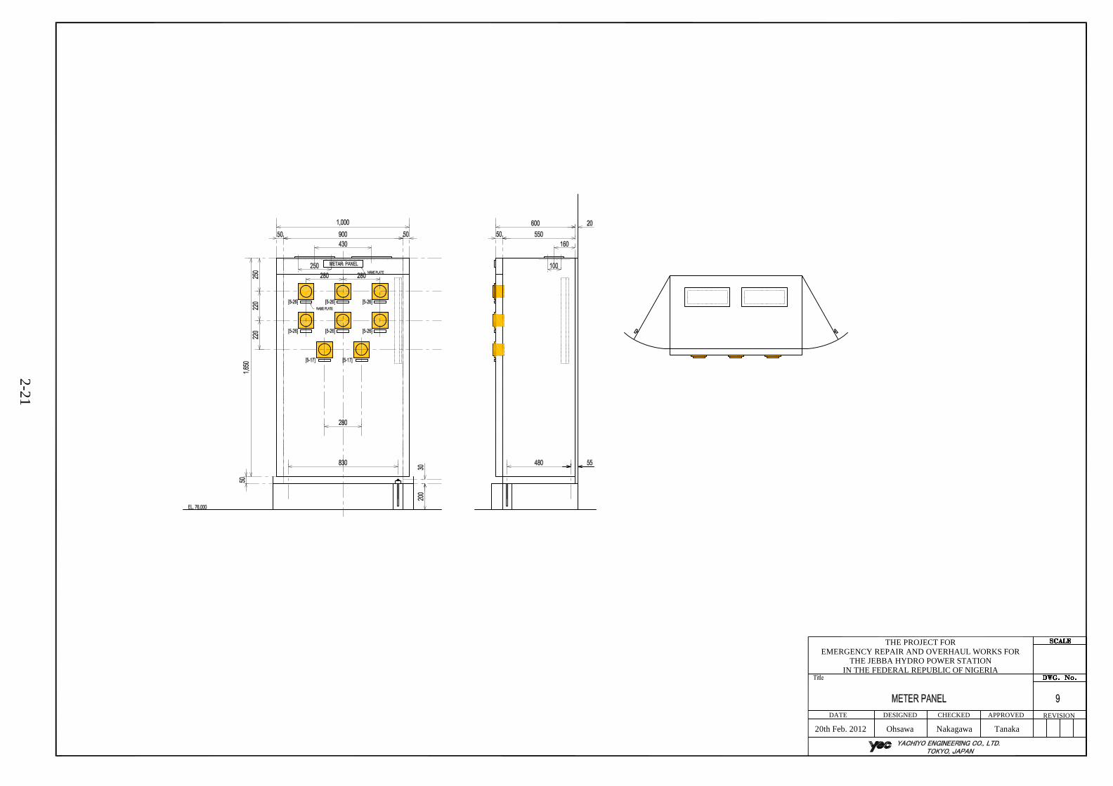
APPROVEDDESIGNEDDATE CHECKED REVISION
THE PROJECT FOREMERGENCY REPAIR AND OVERHAUL WORKS FOR
THE JEBBA HYDRO POWER STATIONIN THE FEDERAL REPUBLIC OF NIGERIA
20th Feb. 2012 Ohsawa Nakagawa Tanaka
2-21
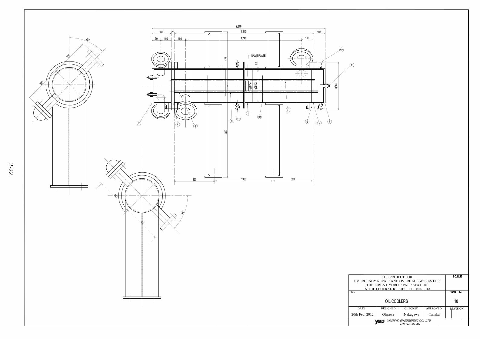
APPROVEDDESIGNEDDATE CHECKED REVISION
THE PROJECT FOREMERGENCY REPAIR AND OVERHAUL WORKS FOR
THE JEBBA HYDRO POWER STATIONIN THE FEDERAL REPUBLIC OF NIGERIA
20th Feb. 2012 Ohsawa Nakagawa Tanaka
2-22

APPROVEDDESIGNEDDATE CHECKED REVISION
THE PROJECT FOREMERGENCY REPAIR AND OVERHAUL WORKS FOR
THE JEBBA HYDRO POWER STATIONIN THE FEDERAL REPUBLIC OF NIGERIA
20th Feb. 2012 Ohsawa Nakagawa Tanaka
2-23

2-24
2-2-4 Implementation Plan
2-2-4-1 Implementation Policy
The Project will be implemented based on the Government of Japan’s Grant Aid for Environment and
Climate Change scheme. The Exchange of Notes (E/N) has been conducted and the Grant Agreement
(G/A) has been concluded between the Government of Japan and Government of Nigeria, and the
Project has been approved by the Government of Japan. The procurement agent will be recommended
by the Government of Japan to the Nigerian side, and JHEP, acting as the mandatory, will manage the
main Project works to ensure that the contract (tender and equipment procurement) is appropriately
and smoothly executed. The following paragraphs describe the basic items and points requiring
particular consideration in the event where the Project is implemented.
(1) Project Implementing Agency
The supervising government agency on the Nigerian side is the Federal Ministry of Power
(FMOP), and the implementing agency is Jebba Hydro Electric Plc (JHEP). Following the
completion of installation works in the Project, JHEP will be responsible for the operation and
maintenance of equipment. In accordance with the framework of the Government of Japan’s
grant aid scheme, JHEP will conduct close liaison and discussions with the Japanese
procurement agent recommended by the Government of Japan, the consultant and the
contractor that are selected by the Japanese procurement agent; it will conduct adequate
explanations and secure the understanding of residents around the target site (Jebba Hydro
Power Station) for the contents of the Project, and it will conduct guidance to ensure that
cooperation for implementation is obtained.
(2) Procurement Agent
The procurement agent will be recommended to the Nigerian side by the Government of Japan,
while FMOP and JHEP, acting as the mandatories, will supervise work to ensure that the
contract (detailed design, tender, equipment procurement and installation) is appropriately and
smoothly executed, and will manage funds on behalf of the relevant agencies on the Nigerian
side.
(3) Consultant
The procurement agent will conclude a design supervision contract with the consultant in
order to supervise the detailed design of the Project facilities and equipment, preparation of
tender documents, procurement and installation of equipment. The consultant will implement
the Project detailed design, prepare the tender documents and supervise the installation and
procurement work. Moreover, when the procurement agent so requests, it will assist the
procurement agent in reviewing the tender qualifications and implementing the tender work.
(4) Contractor
In accordance with the framework of Japan’s Grant Aid scheme, the contractor that has been
selected by the procurement agent in competitive tender will implement the equipment and

2-25
materials procurement and installation works of the Project.
Following completion of the Project, since it will be necessary to continue supplying spare
parts and conducting post-installation service to resolve breakdowns and so on, it will be
necessary to conduct thorough liaison and coordination after the handover of equipment and
materials.
2-2-4-2 Implementation Condition
(1) Suppliers
The Unit 4 generator targeted for rehabilitation is a large-scale unit with rated capacity of 96.4
MW and is produced by a Japanese manufacturer. Since there are no heavy electrical
machinery makers that can manufacture generators of similar scale in Nigeria, it is desirable
to procure the Project equipment from the same maker or a Japanese heavy electrical
machinery maker that has experience of supplying hydroelectric generators of similar scale.
As the Project entails the partial replacement and repair of a generator, it is desirable that the
equipment required in the Project be procured from the heavy electrical maker that
manufactured the generator.
(2) Important Points in Implementation Planning
1) The Project site has a dry season from November to April and a rainy season from May to
October. Since the water volume in Jebba Lake is abundant during the rainy season, Jebba
Hydro Power Station adopts a setup geared to increasing generated electrical energy during
this period. Therefore, concerning the stoppage of Unit 4 due to the Unit 4 rehabilitation
works, it will be necessary to appropriately set the works period to ensure that enough
water flow is secured for conducting the final wet test.
2) After the procured equipment and materials have been landed at Apapa Port, Lagos, they
will be transported overland to Jebba Hydro Power Station, however, because the route has
damaged paving and is in poor condition in parts, it is possible that the transportation route
and carrying capacity will be limited. Therefore, it will be necessary to pay attention to
these points in the transportation plan and schedule planning.
3) The two overhead traveling cranes (225/50/15 t) installed in the powerhouse are currently
not working due to broken brakes, control circuits and power collectors. Since these cranes
are needed for regular maintenance work and also for the Unit 4 generator rehabilitation
works, it will be necessary for the Nigerian Government to repair them by the start of the
rehabilitation works. Moreover, because wire rope and other parts have been used beyond
their service life, it will be necessary to replace such parts during the rehabilitation.
4) Among the existing products, the stator frame and other items contain asbestos. Since there
is a risk that this will fly off when disassembling the core, it will be necessary to conduct
wet work and take ample care in curing and so on. Since Nigeria has no domestic
regulations, it will be necessary to apply Japanese asbestos damage prevention rules with
workers wearing protective breathing apparatus and protective clothing and work being
conducted in a wet environment. Moreover, coil surfaces are covered in varnish and
exterior tape. When disassembling the coils, since there will be a risk of the asbestos parts
being broken, it will be necessary to take ample care regarding curing and so forth.

2-26
Moreover, since such parts have laminated structure on the inner side, the outer surfaces
are covered in varnish. When disassembling field coils, since there will be a risk of the
asbestos flying off, it will be necessary to take ample care regarding curing and so forth
2-2-4-3 Scope of Works
The Japanese side will be responsible for the procurement, installation, testing and adjustment of the
generator equipment and materials, while the Nigerian side will need to repair the crane required for
the Unit 4 rehabilitation works and remove existing equipment in time for the said works.
Table 2-2-2 shows the detailed scope of works on the Japanese and Nigerian sides.
Table 2-2-2 Scope of Works on the Japanese and Nigerian Sides
No. Item
Scope
Remarks Japanese
Side
Nigerian
Side
1 Securing of storage site for equipment and
materials
2 Securing of disassembly and assembly space
for carrying out winding repairs (inside the
generator house)
3 Securing of parking spaces during the works
4 Work spaces inside and outside of the power
station, site office and indoor and outdoor
storage areas
(1) Electrical works
a) Power line expansion works
Expansion of existing low voltage
lines and installation of watt-hour
meters (up to the primary side)
b) Installation of power receiving panel As required
(2) Water supply works
a) Water supply (public waterworks) works
(3) Drainage works
a) Sanitary sewage drainage works (sanitary
sewage and rainwater)
As required
5 Site office furniture (desks, chairs)
6 Manufacture and procurement of equipment
and materials
7 Transportation of equipment and materials
8 Transportation and customs clearance
procedures and tax handling
(1) Responsibility for ocean transport of
equipment and materials to Nigeria
(2) Tax burden and customs clearance
procedures at the port of unloading in
Nigeria
(3) Transportation of procured equipment, etc.
from the port of unloading to the inland site
in Nigeria

2-27
No. Item
Scope
Remarks Japanese
Side
Nigerian
Side
(4) Exemption or bearing of domestic value
added tax on procured materials and
equipment in Nigeria
9 Appropriate storage and safety management
of equipment and materials in the temporary
storage yard on the Project site and site office
during the site works period
10 Steps for acquiring the following
authorizations:
- Authorization needed for conducting
installation works
- Authorization for entering restricted
areas
These authorizations need to be
obtained before Project
implementation.
11 Installation of equipment
12 Temporary power interruptions during the
works period
13 Operating training and guidance for
completion inspections and operation and
maintenance of equipment and products
The Nigerian side will need to select
the members to take part in training.
14 Operation and maintenance of the facilities
and procured equipment
15 Other costs not covered by the grant aid
16 Payment of the following commissions based
on the Banking Arrangement:
(1) Cost of opening an account with a
foreign exchange authorized bank in
Japan
Around 10,000 yen
(2) Bearing of payment commissions Around 0.1% of the project cost
Note: : Indicates the scope of responsibility regarding each item
2-2-4-4 Consultant Supervision
Based on the scheme of the Government of Japan’s Grant Aid Program, the procurement agent will
recruit a consultant to smoothly conduct the implementation design and execution supervision work
according to the principles of the outline design. The procurement agent will conduct overall
management during the period of execution. Under the execution supervision of the Japanese
consultant, the procurement agent will implement site confirmation at the start of the work, witness the
handing-over inspection and confirm other important points. Furthermore, an expert in Japan will
attend plant inspections and pre-shipping inspections of equipment and materials manufactured in
Japan with a view to ensuring that no troubles occur following delivery of materials and equipment to
Nigeria. Furthermore, in line with the progress of the works, it will dispatch expert where necessary to
supervise the works implemented by the contractor.
Moreover, where necessary, the expert will attend plant inspections and pre-shipping inspections of
equipment and materials manufactured in Japan with a view to ensuring that no troubles occur
following delivery of materials and equipment to Nigeria.
2-28
(1) Basic Concept of Execution Supervision
The procurement agent will supervise the progress to ensure that the works are completed on
time, and in cooperation with the contractor, it will supervise and guide the contractor in order
to secure the quality, performance and delivery deadlines specified in the contract and make
sure that the works are carried out safely.
The major points to bear in mind in the consultant supervision are described below.
1) Schedule supervision
The procurement agent will compare progress with the implementation schedule decided
by the contractor in the contract every month or every week in order to adhere to the
delivery deadline given in the contract. In cases where delays are predicted, the
procurement agent will warn the contractor, demand the submission and implementation
of a plan of countermeasures and offer guidance to ensure that the works and delivery of
equipment and materials are completed within the contract period.
- Confirmation of works performance
- Confirmation of equipment and materials delivery
- Confirmation of yield and actual numbers of engineers, skilled workers and
laborers, etc.
2) Quality control
Supervision will be carried out based on the following items to determine whether the
facilities and equipment satisfy the required quality stated in the contract documents
(technical specifications and detailed design drawings, etc.). In cases where doubts arise
over quality and performance, the procurement agent will immediately demand that the
contractor make amendments, revisions or corrections.
- Checking of shop drawings and specifications of materials and equipment
- Attendance of plant inspections of materials and equipment and checking of plant
inspection results
- Checking of shop drawings and onsite trial operation, adjustment and installation
guidelines of materials and equipment
- Supervision of materials and equipment installation works and witnessing of trial
operation, adjustment and inspection
3) Safety control
Discussions will be held and cooperation sought with responsible officers of the
contractor and safety control will be exercised during the construction period in order to
prevent industrial accidents. Important points to consider in safety control on the ground
are as follows.
- Establishment of safety control regulations and appointment of manager
- Prevention of accidents through implementation of periodic inspections of
construction machinery
- Planning of the works vehicles and construction machinery operating routes and
thorough enforcement of safe driving
- Encouragement of laborers to utilize welfare measures and vacations

2-29
4) Fund supervision
The procurement agent will manage the Project cost indicated in the E/N exchanged
between Japan and Nigeria on behalf of the implementing agency (JHEP). After the E/N,
the Project funds will be transferred from JICA to the account established by the
implementing agency with a Japanese bank. Then, after the procurement agent contract is
concluded between the Nigerian side and the procurement agent, the funds will be
transferred from the bank account on the Nigerian side to the account in the Japanese bank
opened by the procurement agent. The procurement agent will pay the contractor(s)
according to the conditions prescribed in the contracts.
(2) Overall relationships in Project implementation
Figure 2-2-5 shows the mutual relationships between Project officials including those during
the consultant supervision.
Figure 2-2-5 Project Implementation Interrelationships
(3) Works Supervisor
The contractor(s) will procure and install the equipment based on the contract made with the
procurement agent. The contractor(swill conduct schedule supervision, quality control and
safety control during the construction period, and the works supervisor of the consultant
recruited by the procurement agent will supervise and instruct the contractors.
2-30
2-2-4-5 Quality Control Plan
The consultant’s works supervisor will carry out supervision and checking based on the following
items to ensure that the contractor secures the quality of Project facilities, equipment and materials
stipulated in the contract documents (technical specifications and implementation design drawings,
etc.). In cases where doubts arise over quality, the consultant will consult with the procurement agent
and demand that the contractor make amendments, revisions or corrections. The procurement agent
will check the work execution performance of the works supervisor and offer guidance where
necessary.
Checking of shop drawings and specifications of equipment and materials
① Attendance of plant inspections of equipment and materials and checking of plant inspection
results
② Checking of packing, transportation and on-site temporary storage methods
③ Checking of shop drawings and installation guidelines for equipment and materials
④ Checking of trial operation, adjustment, test and inspection guidelines of equipment and
materials
⑤ Supervision of site installation works of equipment and materials and attendance of trial
operations, adjustments, tests and inspections
⑥ Checking of completion documents
2-2-4-6 Procurement Plan
Apart from the works materials and expendable items for use in the Project works, the major items of
equipment will be procured from Japan. The main items of equipment to be procured from Japan are
as shown in Table 3-2-14.
2-2-4-7 Operation Guidance Plan
In order to enable effective operation of the supplied equipment after the handing over of the
rehabilitated facilities, the techniques for operating and maintaining the equipment and materials
procured and installed in the Project will be transferred to the Nigerian counterparts during the
installation works and trial operation period.
The detailed OJT plan will be decided within the survey design works scheduled for implementation
from now on.
2-2-4-8 Implementation Schedule
The Project has already been approved for implementation by the Government of Japan, and the
Exchange of Notes (E/N) and Grant Agreement (G/A) have been concluded between the two countries.
Following completion of the Survey, the Agent Agreement (A/A) will be concluded between JHEP, the
implementing agency, and the procurement agent recommended by the Government of Japan and
Project implementation will commence based on the scheme of the Government of Japan’s Emergency
Grant Aid. Project implementation is basically divided into four stages, namely ① implementation
design and selection of works supervision consultant, ② detailed design and preparation of tender
documents, ③ tender for selection of contractor(s) and signing of works contract, and ④ equipment

2-31
and materials procurement and installation works. Figure 2-2-6 shows the Project implementation
schedule.
1 2 3 4 5 6 7 8 9 10 11 12 13 14 15 16 17
Detail D
esign
Procurem
ent an
d In
stallation of
Eq
uip
men
t
Figure 2-2-6 Project Implementation Schedule
2-3 Obligations of Recipient Country
When it comes to implementing the Project, in addition to the scope of works on the Nigerian side
(Table 2-2-2) indicated in 2-2-4-3 Scope of Works in Execution and Procurement, items to be
implemented or borne by the Nigerian side are as follows.
① To provide information and data necessary for the Project.
② To grant labor permits to Japanese persons (and/or corporations) dispatched for the purpose
of the procurement and installation of Project equipment and materials and exempt them
from or bear commissions (or business taxes).
③ To provide the conveniences necessary for entry to Nigeria and stay therein of Project
personnel from Japan and third countries.
④ To appoint specialist engineers and technicians for the transfer of Project operation and
maintenance technology and to attend equipment and materials quality inspections on site.
⑤ To repair the overhead traveling cranes in the powerhouse.
⑥ To secure operators for the overhead traveling cranes.
⑦ To install and adjust the exciter purchased by the Nigerian side.
⑧ To secure the special tools required for rotor rim repairs.
⑨ To secure tools for installation (including lifting devices and sling wires; details are shown in
the appendices)
⑩ To maintain the speed governor on the Unit 4 generator.
⑪ To maintain power supply for the power plant.
⑫ To maintain shaft seals.
(Preparation of drawings and obtaining of approval)
(Production of equipment)
(Transportation of equipment: 1st ship)
(Site test, inspection, Trial run and OJT)
(Total 17 month)
(Preparation of Tender Document)
(Approval of Tender Document)
(Total 4.5 month)
(Installation work)
(Tendering)
(Preparation for Tendering)
(Tender Evaluation)
(Transportation of equipment: 2nd ship)
(Transportation of equipment: 3rd ship)

2-32
⑬ To maintain the servo motor of guide vane.
⑭ To secure the necessary budget and employees needed to properly and effectively operate
and maintain the facilities constructed and equipment and materials procured under Japan’s
Grant Aid.
⑮ To secure the necessary budget and proper treatment of asbestos-containing wastes in
accordance with appropriate procedure which satisfies related Nigerian regulation.
2-4 Project Operation Plan
2-4-1 Basic Concept
In order to conduct stable operation of the hydro power station, it is essential to conduct the
appropriate operation and maintenance (O&M) of turbine and generator equipment, etc. and maintain
the peripheral environment. Accordingly, it is desirable to implement appropriate preventive
maintenance and regular maintenance geared to reducing breakdown rates in facilities and enhancing
reliability, safety and efficiency.
Figure 2-4-1 shows the basic thinking regarding the maintenance of equipment and facilities in the
hydro power station. According to this, it will be necessary to implement the maintenance of
equipment procured and installed in the Project based on preventive maintenance.
Figure 2-4-1 Basic Thinking on Maintenance of Hydro Power Station
In the Project, it is planned to implement OJT on turbine and generator operation and maintenance
under guidance by an engineer dispatched from the Japanese contractor during the installation works
and testing and adjustment period. At the same time, through providing the necessary spare parts, test
apparatus, maintenance tools and O&M manual and proposing the operation and maintenance setup
following the start of operation, the effects of operation and maintenance can be amply realized.
Appropriate Operation and Maintenance
for Hydro Power Station
* Improving of maintenance efficiency
* Improving of operation efficiency
Enhancing of Efficiency
* Improving of electricity quality
* Prevention of electrical accident
* Minimizing of influence against accident
* Quick recovery for accident
* Control of deterioration
Enhancing of Reliability
* Protection against natural disaster
* Protection against artificial obstacles
Enhancing of Safety

2-33
2-4-2 Operation and Maintenance Setup
With JHEP in charge of operation and maintenance following completion of the Project, under the
supervision of PHCN (Power Holding Company Nigeria), the necessary organization and personnel
for conducting appropriate operation of the power utility can be expected.
2-4-3 Periodic Inspection Items
2-4-3-1 Periodic Inspection of Water Turbine Generator
Table 3-4-1 shows the standard periodic inspection items for generator equipment to be procured and
installed in the Project. As is shown in the table, equipment inspections are classified into the
following three types:
① Patrol inspections in which abnormal heating or noises, etc. are inspected everyday based on
the five senses;
② Ordinary inspections in which inspections are conducted on charged sections that cannot be
inspected in routine patrols, for example, torque of equipment bolts, surface dirt on insulated
objects, etc., and
③ Detailed inspections on functions of guide vanes, bearing speed governors and exciters and
for maintaining precision of measuring instruments.
Ordinary inspections are normally conducted once every one or two years, while detailed inspections
are conducted around once every four years. Moreover, it is desirable to replace parts such as meters
and relays, etc. when they are found to have deteriorated performance, deteriorated insulation
performance, worn contacts or altered characteristics in ordinary inspections and detailed inspection.
Table 2-4-1 Periodic Inspection Items in Standard Equipment Inspection
Item Inspection Contents (Method)
Patrol Inspection
Ordinary Inspection
Detailed Inspection
Water turbine
Guide vane operating condition
Water leaks around the guide vane, and state of weak point pins
Leaks from joints
Main bearings oil level and oil supply
Main bearings temperature and cooling water level
Abnormal vibration and noise
Abnormalities in thermometer elements, relays and wiring, etc.
Relationship between guide vane opening and output
Vibration measurement
Abrasion of main axis metal
Abrasion of main axis sleeve, wear of water sealing packing
Runner abrasion and measurement of runner liner gap
Measurement of gap between guide vane shutter face and guide vane and casing
State of abrasion of bearing bush
Oil leaks from pressure oil introduction part and abnormalities in return mechanism
Oil leaks from runner boss and runner servo motor
Guide vane opening and runner vane opening
Generator Rotor hub

2-34
Inspection Item
Inspection Contents (Method) Patrol
Inspection Ordinary
Inspection Detailed
Inspection
Cracks
Rotor
Rotor coil
Rust
Field coil
Winding staining
Insulation resistance
Damper winding
Discharge trace
Condition of terminals
Cracks
Connecting terminals
Fan
Bolt tightening
Air gap
Gap disparity
Stator
Stator core
External appearance
Thermal transformation
Rust
Winding
Winding staining
Condition of insulated items
Insulation resistance
Core duct
Duct staining
Wedge
Winding cohesion
Frame
Loose bolts
Bearings
Bearings
Cracks and damage
Temperature
Oil box
Oil leaks
Lubricating oil
Oil level and staining
Water infiltration
Shaft seal
Insulation resistance
Axial voltage
Brackets
Loose bolts
Vibration

2-35
Inspection Item
Inspection Contents (Method) Patrol
Inspection Ordinary
Inspection Detailed
Inspection
Space heater
Other items; absence of combustible items
Oil cooler, air cooler
Condition of air
Oil leaks
Rust and staining
Pipes
Air, water and oil leaks
Oil pump
Oil leaks
Filter washing
Oil pump temperature
Oil pump vibration
Motor insulation
Strange noise
Brake
Shoe condition
Collector ring
Brush spark
Brush pressure
Brush condition
Collector ring surface
Staining
Others
Noise and vibration
Connection plugs
Interlocking circuits
Protective relays
Rotor stoppers
Condition of spare parts storage
Speed governor
Abnormality on speed governor potentiometer, attachment of dust to converters
Heating, discoloring and disconnection of speed governor resistor
Loose or stretched link pins or wires in speed governor return mechanism
Clogging of speed governor strainer
Lubrication of speed governor moving parts
Hydraulic devices
Operating state and abnormal odor in hydraulic device pumps
Oil level and oil pressure in hydraulic devices
Oil leaks from hydraulic device pipes and cages
Cooling water level and oil temperature in hydraulic device oil collection tanks
Abrasion of hydraulic device gear pumps and side gaps
Abrasion of hydraulic device pumps and motor bearings
Abrasion and wrapping of hydraulic device pilot valves
Foreign materials and sludge in hydraulic device oil

2-36
Inspection Item
Inspection Contents (Method) Patrol
Inspection Ordinary
Inspection Detailed
Inspection
Other devices
Oil leaks from lubricating oil pipes
Operating state of lubricating oil device oil collection tank oil level relays and limit switches
Oil supply and oil level in lubricating oil devices
Clogging of water feeder strainer
Blocking of water feeder pipes and state of leakage
Water supply to water feeder, operating state of current breaker relay
State of drainage device water level detector
Heating, vibration, drainage capacity and lubrication of drainage device pumps
2-4-4 Spare Parts Purchasing Plan
2-4-4-1 Categories of Spare Parts
The spare parts are generally classified according to the following uses:
① Expendable items: Parts that require replacement according to the condition of
abrasion and degradation
② Replacement parts: Parts that need to be replaced for repair due to damage of existing
parts
③ Emergency spare parts: Instruments that urgently need to be replaced to prevent
interruption to power supply
2-4-4-2 Spare Parts Target Equipment and Purchasing Plan
Table 2-4-2 shows the expendable items, replacement parts and emergency spare parts for the
synchronous generator targeted for rehabilitation in the Project. The quantities of replacement parts are
based on a one year supply. However, since there are plans to purchase spare parts in the project that is
currently being implemented by the Nigerian side on Unit 6 and in the repair of other generating units,
there will be no plans to purchase spare parts in the Project.
Table 2-4-2 Expendable Items, Replacement Parts and Emergency Spare Parts
Item QuantityExpendable
Item Replacement
Part Emergency Spare Part
Explanation
Collector ring 1
This is a connecting device for transmitting exciter current from the exciter to the generator; it requires replacement around every 5~10 years.
Carbon brush 90
This exciter side sliding terminal for transmitting exciter current to the collector ring is made from carbon and needs to be replaced around once a year.
Brush holder 2 Device for storing the carbon brush
Spare coil (top) 10 Stator coil (collector ring side)
Spare coil (bottom)
5 Stator coil (water turbine side)

2-37
Item QuantityExpendable
Item Replacement
Part Emergency Spare Part
Explanation
Guide bearing 22 Guide metal used in the generator bearings
Thrust runner 2
Brake shoe 8 Brake sliding surface
Spare current transformer
6
Spare thrust bearing
18
Oil filter 1
Low pressure filter
50
High pressure filter
50
2-4-4-3 Budget Steps for Spare Parts
In the Project, as it will be necessary for the Nigerian side to procure at least one year’s supply of
expendable parts and replacement parts, it will need to budget for the purchase of expendable parts
and replacement parts for a year after completion of the Project.
2-4-4-4 Test Apparatus and Maintenance Tools
It is necessary to procure the test apparatus and maintenance tools that are required to carry out
appropriate maintenance. Test apparatus and maintenance tools are not included in the grant aid,
however, Table 2-4-3 shows the necessary items and quantities for reference purposes assuming
self-procurement by JHEP. In particular, maintenance tools are needed in order to operate and maintain
the generator targeted for repair in the Project.
Table 2-4-3 Maintenance Tools Needed for Maintenance Item Quantity
1. Test apparatus (1) Universal tester 1 set (2) Phase indicator 1 set (3) Voltage detector 1 set (4) Insulation resistance meter (mega) 1 set (5) DC withstand voltage tester (0~100 kV, including DC voltage detector) 1 (6) Basic ground resistance meter 1 (7) Digital multi meter 1 (8) Clamp tester 1 (9) Others 1
2. Maintenance tools (1) Compressor (with die) 1 set (2) Hydraulic jack 50 (3) Welder 5 (4) Burner 5 (5) Grinder 8 (6) Chain block 4 (7) Spider suspending gear 1 (8) Others 1 set
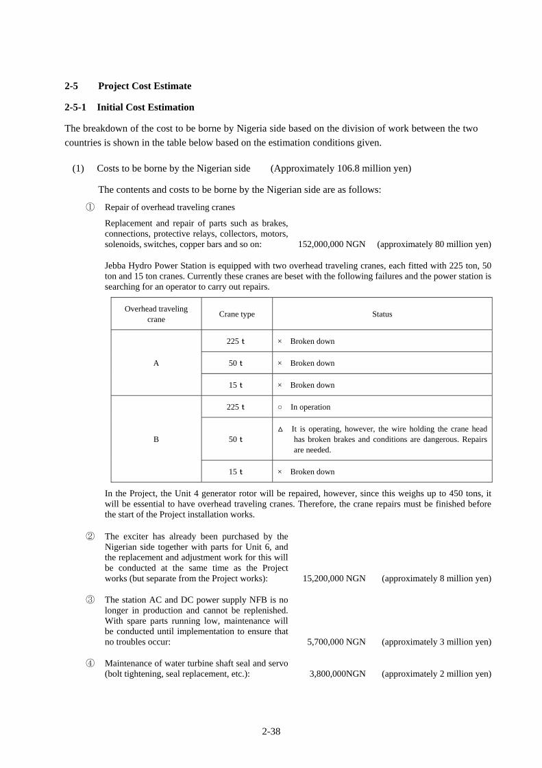
2-38
2-5 Project Cost Estimate
2-5-1 Initial Cost Estimation
The breakdown of the cost to be borne by Nigeria side based on the division of work between the two
countries is shown in the table below based on the estimation conditions given.
(1) Costs to be borne by the Nigerian side (Approximately 106.8 million yen)
The contents and costs to be borne by the Nigerian side are as follows:
① Repair of overhead traveling cranes
Replacement and repair of parts such as brakes, connections, protective relays, collectors, motors, solenoids, switches, copper bars and so on: 152,000,000 NGN (approximately 80 million yen)
Jebba Hydro Power Station is equipped with two overhead traveling cranes, each fitted with 225 ton, 50 ton and 15 ton cranes. Currently these cranes are beset with the following failures and the power station is searching for an operator to carry out repairs.
Overhead traveling crane
Crane type Status
A
225t × Broken down
50t × Broken down
15t × Broken down
B
225t In operation
50t It is operating, however, the wire holding the crane head
has broken brakes and conditions are dangerous. Repairs are needed.
15t × Broken down
In the Project, the Unit 4 generator rotor will be repaired, however, since this weighs up to 450 tons, it will be essential to have overhead traveling cranes. Therefore, the crane repairs must be finished before the start of the Project installation works.
② The exciter has already been purchased by the Nigerian side together with parts for Unit 6, and the replacement and adjustment work for this will be conducted at the same time as the Project works (but separate from the Project works): 15,200,000 NGN (approximately 8 million yen)
③ The station AC and DC power supply NFB is no longer in production and cannot be replenished. With spare parts running low, maintenance will be conducted until implementation to ensure that no troubles occur: 5,700,000 NGN (approximately 3 million yen)
④ Maintenance of water turbine shaft seal and servo (bolt tightening, seal replacement, etc.): 3,800,000NGN (approximately 2 million yen)

2-39
⑤ Overhead traveling crane operators during the installation works period (10.5 MM): 5,460,000NGN (approximately 2.8 million yen)
⑥ Expendable items (1 year supply) 3,800,000 NGN (approximately 2 million yen)
⑦ Tools 13,300,000 NGN (approximately 7 million yen)
⑧ Authorization to Pay (A/P) fees: Approximately
0.1% of E/N amount
(approximately 2 million yen)
(2) Estimation criteria
① Estimation point: August 2011
② Exchange rate: 1 US$=82.49 yen (TTS mean value from February to July
2011)
1 NGN=0.527 yen (TTS mean value from February to July
2011)
③ Works and procurement period: The detailed design and equipment procurement and
installation period is as shown in the implementation
schedule.
④ Other points: The Project will be implemented according to the Grant
Aid Scheme of the Government of Japan.
2-5-2 Operation and Maintenance Costs
Jebba Hydro Power Station has continually operated the power station for 26 years since it was opened,
and it will continue to operate and maintain the facilities and equipment provided in the Project.
Moreover, as the Project entails repair of an already operating generator, it will not require any new
employment of personnel.
Moreover, in order to soundly operate the generator to be rehabilitated in the Project, it will be
necessary to always keep the spare parts (expendable parts and replacement parts) shown in Table
2-4-2 on hand and to budget for necessary parts (approximately 2 million NGN/year). Since repair and
maintenance costs in the power station over the past five years have amounted to approximately 98
million NGN, it should be possible for Jebba Hydro Power Station to afford the cost of maintaining
the equipment of Unit 4 that is to be rehabilitated in the Project.

CHAPTER 3
PROJECT EVALUATION

3-1
Chapter 3 Project Evaluation
3-1 Preconditions
3-1-1 Preconditions for Project Implementation
Project implementation is conditional on securing space for parts exchange work, obtaining
environmental permission for wastes and implementing the obligations of the recipient country
indicated in Section 2-3. Accordingly, in addition to definitely carrying out routine maintenance, it will
be necessary for the contractor to appropriately treat waste according to the National Environmental
Standard of Nigeria, to confirm the budget on the local side and bind a contract for the crane repair
works, etc.
3-1-2 Preconditions and External Conditions for Achieving the Overall Project Plan
In order to realize and sustain the Project effects, the issues that need to be tackled by the Nigerian
side will be as follows.
(1) Make sure that the water intake for the water turbine generator is enough for generating
power.
(2) Make sure that sufficient budget is secured to pay for the personnel and materials needed for
maintenance.
(3) Maintenance concerning power generation revenue is smoothly conducted and the financial
condition is sound.
(4) Ensure autonomously procured cranes and tools are ready so that plans are not hampered on
either side.
3-2 Necessary Inputs by Recipient Country
In order to realize and sustain the Project effects, the Nigerian side will need to tackle the following
issues.
(1) Before start of works
① It will be necessary for the Nigerian side to complete the repair of the overhead traveling
cranes in the power station building before the start of the Project works. In the Project, the
Unit 4 generator rotor will be repaired, however, since this weighs up to 450 tons, it will be
essential to have overhead traveling cranes. Therefore, the crane repairs must be finished
before the start of the Project installation works.
② The Nigerian side will need to definitely procure the special tools required for rotor rim
repairs and the tools required for installation works (including suspending apparatus and
wire) in Unit 6. In the Project, the Unit 4 generator rotor will be repaired, however, since this
weighs up to 450 tons, it will be essential to have special tools for suspending this as well as
repair tools. Therefore, these tools must be procured before the start of the Project
installation works.
③ The Nigerian side will need to secure the budget for its scope of works and definitely execute
those works before the start of works by the Japanese side.
3-2
④ The Nigerian side will need to definitely make applications for permission to the Ministry of
Environment concerning the works and waste products including asbestos before the start of
works by the Japanese side.
(2) During works and after the start of operation
① In tandem with the generator procurement and installation works to be implemented by the
Japanese side in the Project, the Nigerian side will need to smoothly carry out its obligations
such as formulation and implementation of the power station operating plan, etc. It will be
necessary to appoint responsible engineers for each target area in the Project in order to
compile the schedule plan, staff plan and equipment and materials purchasing plan, etc. and
generally expedite the works.
② The demand for electric power in Nigeria is growing rapidly in line with economic growth,
etc. In line with this, generated electric energy at Jebba Hydropower Station is also
increasing, and JHEP will need to secure autonomous and sustainable development with a
view to securing revenue from power tariffs.
③ In order to secure a stable power station operating setup, it will be necessary to implement
periodic dam patrol inspections, cut down trees around the dam and conduct preventive
maintenance to ensure stable dam operation and avert accidents in civil engineering facilities
such as the water discharge dam and gates, etc.
④ It will be necessary to promptly appoint the engineers who will take part in the Project OJT,
dispatch them to the training and ensure that the contents are horizontally extended to the
other engineers who can’t take part in the training.
⑤ It will be necessary to take tax exemption measures and provide other conveniences
regarding the necessary equipment and materials for the Project and the Japanese nationals
who are dispatched.
⑥ Since the existing transmission substations and Jebba Hydropower Station are operated under
different setups, it will be necessary for the Nigerian side to constantly share information and
conduct maintenance for dealing with accidents and so on.
3-3 Important Assumptions
The external conditions that are required in order to realize and sustain the Project effects are as
follows.
(1) Concerning the higher goal
- Policies concerning hydropower generation remain unchanged.
- The political and economic situation is stable.
(2) Concerning the Project objectives
- Operation and maintenance is carried out on a sustained basis.
- Tariff collections and financial support are continued.
- Security of facilities is maintained.

3-3
(3) Concerning the anticipated outputs
- The dam and power generating facilities are adequately operated.
- The operation and maintenance plan is implemented.
- Residents can afford the connection costs and electricity tariffs (government).
3-4 Project Evaluation
3-4-1 Relevance
As is indicated below, since the Project will contribute to the realization of Nigeria’s development
plans and energy policy and impart benefits to the general public including impoverished people, it is
deemed to have high relevance as an aid undertaking.
(1) Benefiting population
As a result of Project implementation, it will be possible to supply stable power to
approximately 140 million residents of Nigeria.
(2) Contribution to stable operation of public and social welfare facilities
Project implementation will contribute to the stable supply of electricity to public and social
welfare facilities such as schools and hospitals. Since power facilities will be improved and
problems such as power interruptions and voltage drop will be mitigated when operating x-ray
and other medical instruments in the said public facilities and using power tools in industrial
plants, it will become possible to use such instruments and tools for longer times, thereby
making a contribution to improving the living conditions of residents.
(3) Project contributing to national development plans in Nigeria
Within the 7 Point Agenda proposed by President Yar’Adua in May 2007 in the areas of, (1)
power and energy, (2) security, (3) land reform, (4) food security, (5) education, (6) wealth
creation and (7) transport and infrastructure, power and energy is the most important item.
According to the National Energy Policy, it is planned to expand the production and
utilization of energy with a view to promoting industry.
Moreover, the Ministry of Energy is taking the initiative in compiling the Renewable
Electricity Policy Guidelines aimed at expanding supply of power made using renewable
energy sources, and the government considers it necessary to promote power supply from
renewable energy sources as a means of bolstering power generation and supply capacity to
match economic and social development, diversifying power generation sources from the
viewpoint of energy security and promoting rural electrification. The Renewable Electricity
Action Program is also currently being compiled in order to indicate concrete measures for
manifesting the said guidelines in future. Project implementation will lead to the upgrading
and expansion of renewable energy power generating facilities, thereby leading to major
improvement in power interruptions and enhancing the power supply of Nigeria that is in need
of urgent improvement.

3-4
(4) Japan’s Grant Aid Scheme
The main equipment for the Project will be procured in Japan, and the work is scheduled to
finish within the E/N time limit. Therefore, since the Project contents and schedule are
feasible and reasonable for implementation within the scope of the grant aid scheme, it should
be possible to implement without any major difficulty. Since JHEP is a state-run enterprise,
the Project contents are both relevant and urgently required as described earlier and there is no
problem concerning the maintenance setup, there should not be any impediments to
implementing the Project under the Government of Japan’s grant aid scheme.
(5) Necessity and superiority of using Japanese technology
The Unit 4 generator, which is targeted for improvement in the Project, is a large-scale unit
made by a Japanese maker and possessing rated output of 96.4 MW. Since Nigeria has no
makers capable of making a generator of similar scale, and the unit targeted for rehabilitation
in the Project was made in Japan, there is deemed to be necessity and technical advantage in
having a Japanese enterprise implement the Project work.
3-4-2 Effectiveness
The following effects are anticipated as a result of Project implementation.
(1) Quantitative effects
1) Maximum output
Unit 4 is currently unable to generate more power due to vibrations and so on even if the
amount of water intake from the dam is increased. Since the Project will result in
completion of repairs and upgrading of the meters required to monitor temperature, etc. in
coils, thrust bearings and coolers, etc., it will become possible to safely acquire output and
reduce the maintenance burden. Incidentally, as the reference value, output in 2010 has
been adopted as the value for during and after 2009, when the accident occurred.
Indicator Reference Value (2010) Target Value (2016)
Maximum output (MW) 45.9 MW (47.6%) 96.4 MW (100%)
2) Available electric energy
Through replacing the rotor coils, stator coils and thrust bearings of generator unit 4 in the
Project, vibrations during operation will be reduced and it will become possible to provide
continuous power supply into the future. In other words, setting the annual generated
amount of power of Unit 4 as the quantitative indicator, the goal is to restore stable power
supply based on rehabilitation aiming to attain an average value of this generated amount
equivalent to the value prior to the accident in 2009. Specifically, the goal shall be to
achieve an average amount of power generation in three years after Project completion
equivalent to the mean value of power generation in the 10 years prior to the accident.
(The appendices indicate movements in the generated amount of power at Jebba
Hydropower Station).
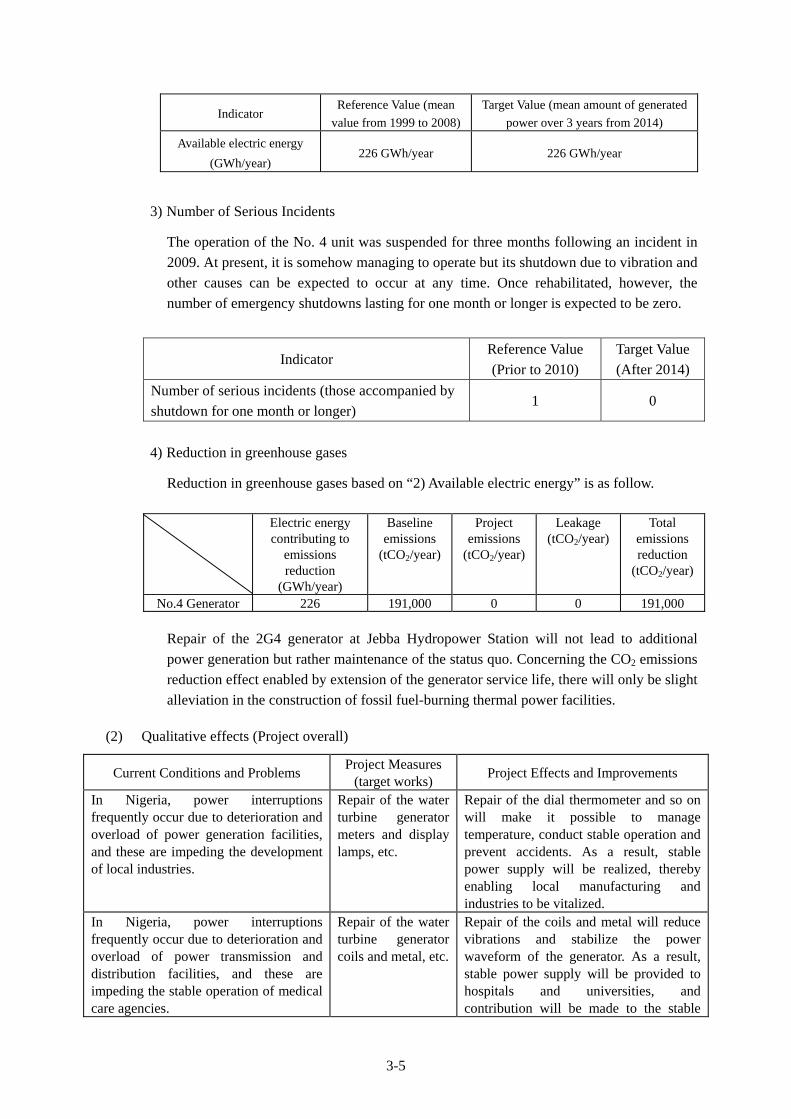
3-5
Indicator Reference Value (mean
value from 1999 to 2008)
Target Value (mean amount of generated
power over 3 years from 2014)
Available electric energy
(GWh/year) 226 GWh/year 226 GWh/year
3) Number of Serious Incidents
The operation of the No. 4 unit was suspended for three months following an incident in
2009. At present, it is somehow managing to operate but its shutdown due to vibration and
other causes can be expected to occur at any time. Once rehabilitated, however, the
number of emergency shutdowns lasting for one month or longer is expected to be zero.
Indicator Reference Value
(Prior to 2010)
Target Value
(After 2014)
Number of serious incidents (those accompanied by
shutdown for one month or longer) 1 0
4) Reduction in greenhouse gases
Reduction in greenhouse gases based on “2) Available electric energy” is as follow.
Electric energy
contributing to emissions reduction
(GWh/year)
Baseline emissions
(tCO2/year)
Project emissions
(tCO2/year)
Leakage (tCO2/year)
Total emissions reduction
(tCO2/year)
No.4 Generator 226 191,000 0 0 191,000
Repair of the 2G4 generator at Jebba Hydropower Station will not lead to additional
power generation but rather maintenance of the status quo. Concerning the CO2 emissions
reduction effect enabled by extension of the generator service life, there will only be slight
alleviation in the construction of fossil fuel-burning thermal power facilities.
(2) Qualitative effects (Project overall)
Current Conditions and Problems Project Measures
(target works) Project Effects and Improvements
In Nigeria, power interruptions frequently occur due to deterioration and overload of power generation facilities, and these are impeding the development of local industries.
Repair of the water turbine generator meters and display lamps, etc.
Repair of the dial thermometer and so on will make it possible to manage temperature, conduct stable operation and prevent accidents. As a result, stable power supply will be realized, thereby enabling local manufacturing and industries to be vitalized.
In Nigeria, power interruptions frequently occur due to deterioration and overload of power transmission and distribution facilities, and these are impeding the stable operation of medical care agencies.
Repair of the water turbine generator coils and metal, etc.
Repair of the coils and metal will reduce vibrations and stabilize the power waveform of the generator. As a result, stable power supply will be provided to hospitals and universities, and contribution will be made to the stable
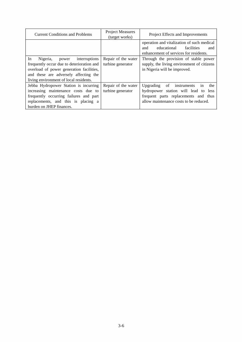
3-6
Current Conditions and Problems Project Measures
(target works) Project Effects and Improvements
operation and vitalization of such medical and educational facilities and enhancement of services for residents.
In Nigeria, power interruptions frequently occur due to deterioration and overload of power generation facilities, and these are adversely affecting the living environment of local residents.
Repair of the water turbine generator
Through the provision of stable power supply, the living environment of citizens in Nigeria will be improved.
Jebba Hydropower Station is incurring increasing maintenance costs due to frequently occurring failures and part replacements, and this is placing a burden on JHEP finances.
Repair of the water turbine generator
Upgrading of instruments in the hydropower station will lead to less frequent parts replacements and thus allow maintenance costs to be reduced.