presentation topic 3: simulation as part of control design ... · – operational and actuator...
TRANSCRIPT

Copyright 1998 DLMattern
PresentationPresentation
Topic 3: Simulation Topic 3: Simulation
as part of Control Design & Evaluationas part of Control Design & Evaluation

Copyright 1998 DLMattern
OutlineOutline
Simulation TerminologyPurpose of SimulationRevisit The Control Design ProcessSimulations Required for Control DesignModel Based RoutinesSoftware ToolsSummary

Copyright 1998 DLMattern
Simulation TerminologySimulation Terminology
Cycle Deck - Steady Flow Path Model of Engine CycleComponent Level Model (CLM)– Physical based model built from individual components
Piecewise Linear Model - scheduled linear modelsContinuous - requires numerical integrationDiscrete - integration implicit. Already transformed.Non-realtime - simulation time unrelated to “time”Realtime - simulation time a linear function of “time”– frame-time: simulation update period.

Copyright 1998 DLMattern
Purpose of SimulationPurpose of Simulation
Save Time and Money– Numerical Trial and Error Before Cutting Metal– Provide Platform for Spreadsheet type “what-if” analyzes– Control System Design and Validation
Verify Understanding of the Physics– Validate Model Against Observations
Starting Point for Model Based Approaches– An onboard model can be used for Controls, Diagnostics,
Engine & Fleet Maintenance

Copyright 1998 DLMattern
Revisit The Control Design ProcessRevisit The Control Design Process
Model Creation & Validation– Simplified cycle deck plus dynamics
Linearization– Generation of Design Point Linear Models
Linear Control Design at design pointsIncorporation of Nonlinearities:– Operational and actuator limits, scheduling, mode
logic, limit and integrator windup protection
Realtime Simulation: check timingRealtime I/O Checkout: hard & software
Modeling
Linearization
Control Design
Nonlinear Design
Timing
I/O Checkout
15%
45%
15%
15%
10%
given
percent time estimates assume you start with a validated dynamic model and experienced engineers working on all tasks

Copyright 1998 DLMattern
Simulations Required for Control DesignSimulations Required for Control Design
Cycle Deck Model for Schedule GenerationDynamic Nonlinear Model for Linear Model Creation and for the Design and Evaluation of Nonlinear Portions of the Control DesignDynamic Linear Models for Linear Control DesignReal-Time Dynamic Model (covered in another topic)– for Timing Evaluation– with Inputs and Outputs for Hardware-in-the-loop testing
» “wet bench” (hydraulic) testing of actuators.

Copyright 1998 DLMattern
Cycle Deck Model for Steady State Cycle Deck Model for Steady State PerformancePerformance
Once performance is obtained, the cycle deck can be used to define the engine steady state operating schedule.Historically these models have been written in FORTRAN because the tools used by component groups and performance people have typically been written in FORTRAN.– The main advantage that FORTRAN has over C for these types of
computations is multidimensional arrays and efficient compilers for vector, parallel, and multi-processing.

Copyright 1998 DLMattern
Cycle Deck Flow Path for a Turbofan EngineCycle Deck Flow Path for a Turbofan Engine
from Society of Automotive Engineering, SAE Aerospace Recommended Practice: ARP-1257A & ARP 755Assumptions: All flows are balanced, no volume dynamics.
Inle
t
Fan
Com
pres
sor M
ap
HP
C M
ap
Com
bust
or
LPT
Exh
aust
Duc
tFa
n D
uct
Mix
ing
Sec
tion
Afte
r bur
ner
Noz
zle
XM
Pamb
Tamb
W1
P1
T1
Inle
t Duc
t W2A
P2
T2
W25
P25
T25
W25
P25
T25
W3
P3
T3
W4
P4
T4 HP
T
W45
P45
T45
W5
P5
T5
W6
P6
T6
W16
P16
T16
W6
P6
T6
W7
P7
T7
F
W8
P8
T8
steady state control schedulefan-cvg cvg wf-fuel A8-area

Copyright 1998 DLMattern
Dynamic Nonlinear ModelDynamic Nonlinear Model
Rotor Dynamics added to Cycle Deck– Time Derivative of Steady State Energy Balance
» d/dt{ Kinetic Energy } = d/dt { Net Energy Into System }
» d/dt { 1/2 J ω2 } = Shaft Power in - Shaft Power out
» ωdot * J ω = (Turbine Power - Compressor Power)» ωdot = (Net Shaft Power)/(Jω) (Note: no one is currently measuring net
shaft torque online and using this measurement for control or diagnostics )
Temperature Heat Soaks - first order mass capacitance– Metal temperatures and how they affect clearances
Pressure Dynamics: (for high bandwidth model)– Engine Pressure Ratio (EPR), fan bypass duct pressure ratio

Copyright 1998 DLMattern
Dynamic Nonlinear ModelsDynamic Nonlinear Models
To validate your model with test data, you will need an appropriate set of sensors and actuators.
SensorRotor Speeds: N1, N2Pressures: Pamb, PT2,
P25, PS3, PS16, PS56Temperatures: Tamb, T2,
T25, T3, T4, T56
ActuatorsFuel Flow: WF36, W6Nozzle Area, A8Inlet Guide Vanes, IGVCore Variable Stator Vanes, VSVHPC Bleed Flow, WB3Variable Area Bypass Injector, VABI(door to bypass duct)
EstimatesEPR: P6/PT2OPR: PS3/PT2DP/P: (P21-PS14)/P14Gross Thrust: FG9Mass flows, w2, w12, w21, w6
Fan IGV
PambTamb
VABI-A14 VABI-A16
A8 A9
WF6- Afterburner
PS14P25T25
T4 PS16 PS56T56
PS3T3
PT2T2 N1 N2
WF36
VSVWB 3
MIXING
PLANE

Copyright 1998 DLMattern
Dynamic Linear ModelsDynamic Linear Models
Once the Dynamic Nonlinear Model has been validated and frozen, you can generate linear models.– Linearization tools using perturbation are magnitude dependent
and may require trial end error to obtain an appropriate “delta”.– MATLAB [A,B,C,D] = LINMOD( 'SYS', X, U, PARAM, XPERT, UPERT )
» set the perturbation levels for all of the elements of X and U» NOTE: LINMOD only does positive perturbations.
Better method does positive and negative and averages the two.
Only important if operating point is highly nonlinear.
» Many of the Simulink Blocks don’t linearize properly.Example: Continuous Time Delay.
– ISI’s SystemBuild actually provides a PADE’ approximation duringlinearization of their continuous time delay.
Copyright 1998 DLMattern
Dynamic Linear ModelsDynamic Linear Models
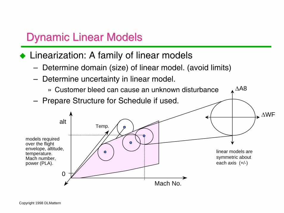
Linearization: A family of linear models– Determine domain (size) of linear model. (avoid limits)– Determine uncertainty in linear model.
» Customer bleed can cause an unknown disturbance
– Prepare Structure for Schedule if used.
Mach No.
alt
0
∆WF
∆A8
Temp.
linear models are symmetric about each axis (+/-)
models requiredover the flight envelope, altitude, temperature. Mach number, power (PLA).
Copyright 1998 DLMattern
Dynamic Linear Models: ReferencesDynamic Linear Models: References
Linearization, see– Sugiyama N., “Derivation of ABCD System Matrices from
Nonlinear Dynamic Simulation of Jet Engine”, National Aerospace Lab, Tokyo, Japan, AIAA 92-3319, 28th Joint Propulsion Conf., 1992.
Schedule of Linear Controller Gains– Use a neural network to provide the scheduling of the gains.
» Lin Shih-Tin, Lee Chun-Mo, “Multivariable Control of the J-85 Turbojet Engine for Full Flight Envelope Operation”, AIAA Journal of Guidance, Control, & Dynamics, Vol 19, #4, July-Aug. 1996, p 913
Shih-Tin - National Chung-Hsing University, Taichung, Taiwan
Chun-Mo Lee - China Motor Corporation, Taiwan.

Copyright 1998 DLMattern
Dynamic Linear Models: Design ModelDynamic Linear Models: Design Model
Linear Design Plant Model– Scaled plant, actuators, sensors, weights– Weighted inputs, sensitivity, complementary sensitivity
ScaledLinear Plant
u yucmd ActuatorModels
SensorModels
MeasurementNoise
Exogenouscommands
Wc(s)
WT(s)
WS(s)
Z
Y
U
W
NoiseFilter
CmdFilter e
FrequencyWeights
Mixed Sensitivity, H-inf Model StructureMay not need all this complexity for simple systems
u y
zw
K
G

Copyright 1998 DLMattern
Dynamic Linear Models: ScalingDynamic Linear Models: Scaling
Scaling for a linear design, relative to operating point– Consider operational and actuator limit– Goal is a symmetric linear design– Don’t typically use the nominal operating point value to scale.
» Use size of operating range
∆N1
∆EPR
G(s)
FromLinearization
Process
Wf
A8
N1
EPRSu1
Su2
Sy1
Sy2
Wfs
A8s
N1s
EPRs

Copyright 1998 DLMattern
Other Applications for these ModelsOther Applications for these Models
You spent all the time and effort developing these models. What else can you use them for.– Object Oriented Programming: reuse of the functions:
compressor and turbine maps, combustor model, dynamic equations.
– Model Based Control Design– Model Based Diagnostics & Maintenance
» Everything is compared against a fleet baseline modelComparison can be used for component life estimates.
Copyright 1998 DLMattern
Object Oriented Approach to ModelingObject Oriented Approach to Modeling
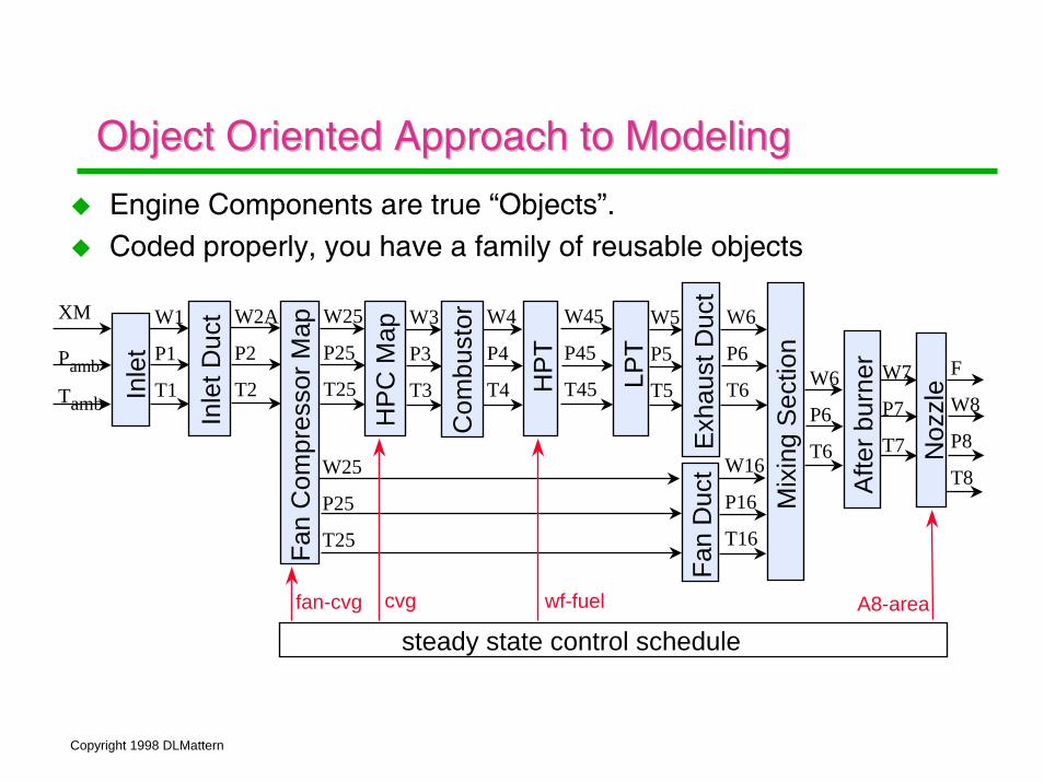
Engine Components are true “Objects”.Coded properly, you have a family of reusable objects
Inle
t
Fan
Com
pres
sor M
ap
HP
C M
ap
Com
bust
or
LPT
Exh
aust
Duc
tFa
n D
uct
Mix
ing
Sec
tion
Afte
r bur
ner
Noz
zle
XM
Pamb
Tamb
W1
P1
T1
Inle
t Duc
t W2A
P2
T2
W25
P25
T25
W25
P25
T25
W3
P3
T3
W4
P4
T4 HP
T
W45
P45
T45
W5
P5
T5
W6
P6
T6
W16
P16
T16
W6
P6
T6
W7
P7
T7
F
W8
P8
T8
steady state control schedulefan-cvg cvg wf-fuel A8-area

Copyright 1998 DLMattern
Model Based ControlModel Based Control
Error between engine and model used in controller– Internal Model Control (IMC), Robust Process Control, Morari,
M., Zafiriouu E., 1989– Alternative approach to handle limits– Technique to measure model uncertainty, “online”
Engine
Model
Controller-
+
Cmds
Auxilliary Model outputs could also be use as analytical redundant sensors and measurements in dual redundancy sensor fault detection voting schemes.
estimates: -fuel flow- stall margin- thrustOnline model could also be used
in steady state optimization. Performance Seeking Control, NASA Dryden
Copyright 1998 DLMattern
Model Based Diagnostics & MaintenanceModel Based Diagnostics & Maintenance
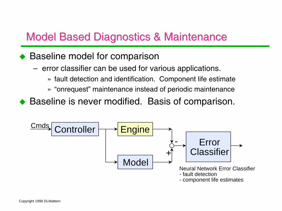
Baseline model for comparison– error classifier can be used for various applications.
» fault detection and identification. Component life estimate» “onrequest” maintenance instead of periodic maintenance
Baseline is never modified. Basis of comparison.
Engine
Model
Controller-
+Error
Classifier
Cmds
Neural Network Error Classifier- fault detection- component life estimates

Copyright 1998 DLMattern
Software ToolsSoftware Tools
Object Oriented Tools for the Control Design Process:– The MathWorks: Matlab, Simulink, Realtime Workshop– Integrated Systems, Inc.: Xmath, SystemBuild, AC100– Visual Solutions: Vissim– others lesser packages, Maple, Mathmatica, …etc.
Rapid Prototyping tools help to tie together the nonreal-time and the real-time development.– ISI’s AC100– MathWorks RealTime Workshop
» 3rd party hardware

Copyright 1998 DLMattern
Software ToolsSoftware Tools
NOTE: ISI’s SystemBuild is a superior simulation environment compared to the MathWorks Simulink. However, while ISI’s Xmath is powerful, has a steep learning curve. It is not the same as MatrixX.– Xmath uses Parameter-Dependent-Matrices (PDM) in ALL
functions. This requires a reformulation of the way you think about systems. (3D matrices)
SystemBuild has a one step process from continuous to discrete and back. Simulink has no such path, but theMathWorks RealTime Workshop will run continuous systems.

Copyright 1998 DLMattern
SummarySummary
Simulation can save you time and moneyThere are a number of different design models:– Cycle Deck, Nonlinear Dynamic Model, Linear Dynamic Model
from Linearization, and Real-Time Models (to be discussed next)
Models must be validated.– Critical to understanding the system physics– Useful in Model Based Techniques, controls & diagnostics
Software tools available for Simulation– Icon based programming environments so you don’t have to
develop your own tools and can concentrate on your application.