presentazione di powerpoint - nccrd.innccrd.in/iciwsindia2015-assets/docs/ranzi2.pdf · c2h6. c3h8....
TRANSCRIPT
Winter Combustion School IIT Madras December 2015
Combustion KineticsLow and high temperature combustionIdeal ReactorsPAH and Soot
Eliseo Ranzi
Dipartimento di Chimica, Materiali e Ingegneria Chimica “G. Natta”Politecnico di Milano

Winter Combustion School IIT Madras December 2015
Outline 2
2.a Chemical Kinetics:Combustion of methane.Low and high temperature combustion of hydrocarbons.
2.b Reactions in Ideal Reactors with negligible molecular transport: plug flow and stirred reactors, shock tubes and rapid compression machines. Premixed and diffusion flames.
2.c PAH and Soot formation mechanisms.

Winter Combustion School IIT Madras December 2015 3
C 2H 6
C 2H 5
C 2H 4
C 2H 3
C 2H 2
Aromatics
Soot
Pyrolysis
O2
CHi
CH3OOH
CH3OH
CH2OH
O2
OH
Oxidation
CH3OO
CH3
CH3O
CH2O
HCO
CO
CO2
CH4
NOx
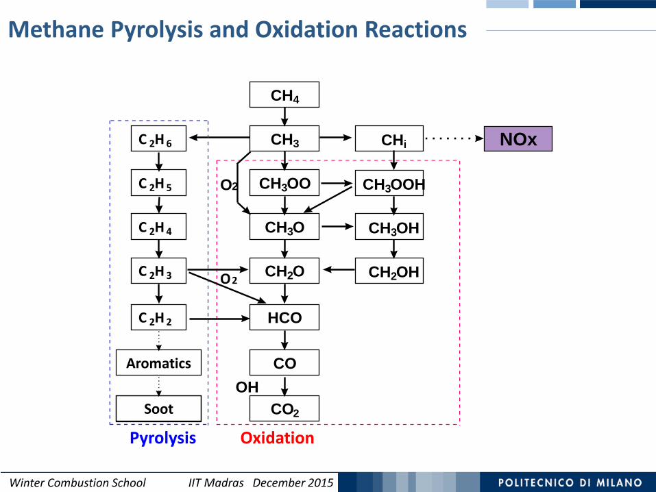
Detailed Kinetics of Methane CombustionCH4+ 2 O2 CO2 + 2 H2O
It is important to include all the relevant reactions and the proper relative
selectivity of parallel reaction paths.
Winter Combustion School IIT Madras December 2015
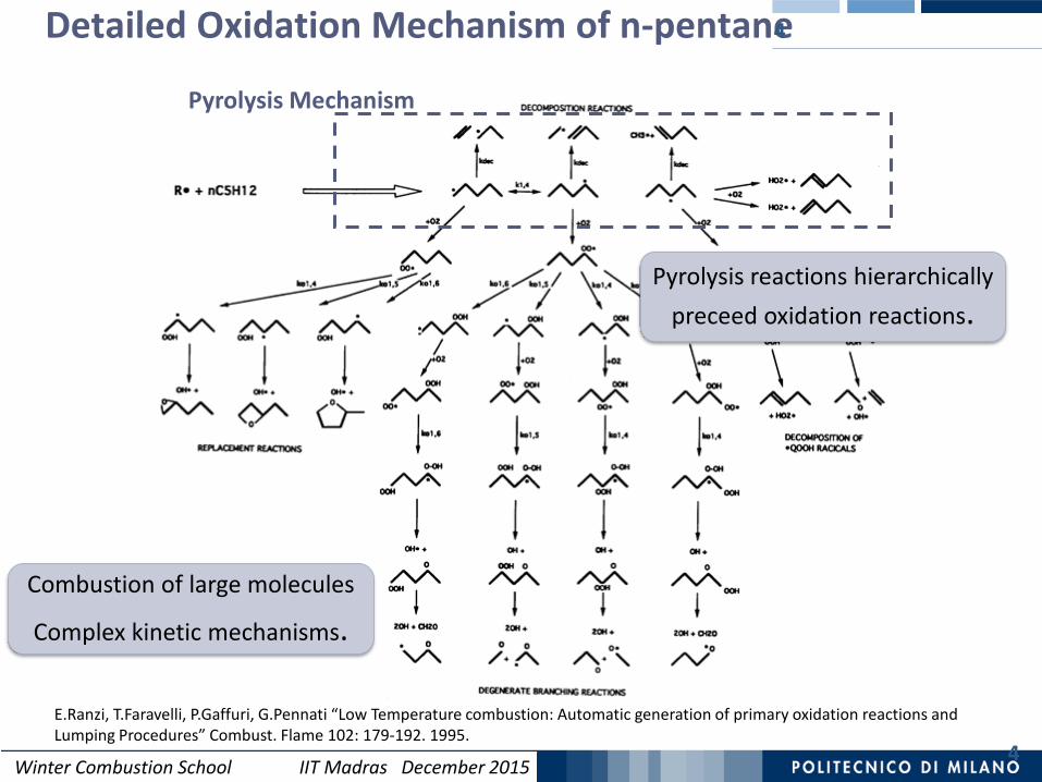
Detailed Oxidation Mechanism of n-pentane
4
4
Pyrolysis Mechanism
Pyrolysis reactions hierarchically preceed oxidation reactions.
E.Ranzi, T.Faravelli, P.Gaffuri, G.Pennati “Low Temperature combustion: Automatic generation of primary oxidation reactions and Lumping Procedures” Combust. Flame 102: 179-192. 1995.
Combustion of large molecules
Complex kinetic mechanisms.
Winter Combustion School IIT Madras December 2015
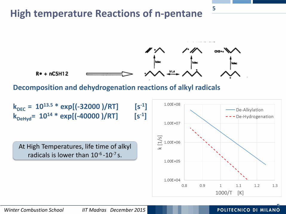
High temperature Reactions of n-pentane
5
5
At High Temperatures, life time of alkyl radicals is lower than 10-6 -10-7 s.
Decomposition and dehydrogenation reactions of alkyl radicals
kDEC = 1013.5 * exp[(-32000 )/RT] [s-1]kDeHyd= 1014 * exp[(-40000 )/RT] [s-1]

Winter Combustion School IIT Madras December 2015
High Temperature Oxidation MechanismDecomposition of Large Molecules
6
High Temperature mechanism mainly involves interactions amongstsmall and stable radicals (H, CH3, C2H3, C3H3, …)and small stable species such as C2H4 and C2H2
as well as oxigenated species ( O2, O, OH, HO2, …..)
Alkyl-radicals
Alkanes
Alkenes
Small radicals
High Temperature mechanism is not very sensitive to the structure of the hydrocarbon fuel
6

Winter Combustion School IIT Madras December 20157
High Temperature Combustion Processes
Combustion reactions proceed via a chain radical mechanism.
Reaction Classes.
Chain Initiation Reactions (Formation of radicals from stable species):C3H8 C2H5 + CH3
Chain Propagation Reactions (propagate the reaction chain):OH + C3H8 H2O + C3H7( nC3H7 CH3 + C2H4 and iC3H7 H + C3H6 )
Chain Termination Reactions (radical recombination):
CH3 + CH3 C2H6
A very sensitive high temperature combustion reaction is the
Chain Branching Reaction (increase the # of radicals).H + O2 O + OH

Winter Combustion School IIT Madras December 20158
At High Temperatures,H radical strongly influences the combustion rate
All the reactions favouring the H radical production increase the combustion rates: e.g., dehydrogenation reaction of ethyl radical (C2H5):
C2H5 C2H4 + H
For this reason methane and ethane show the lowest and the highestcombustion rate, respectively.
High Temperature Combustion Processes
On the contrary, CH3 radical recombination to form ethane:CH3 + CH3 C2H6
reduces the radical concentration and the reaction rate.
n-butyl radicals form both the radicals CH3 and C2H5 :1 C4H9 C2H4 + C2H5
n C4H10 2 C4H9 C3H6 +CH3
Winter Combustion School IIT Madras December 2015
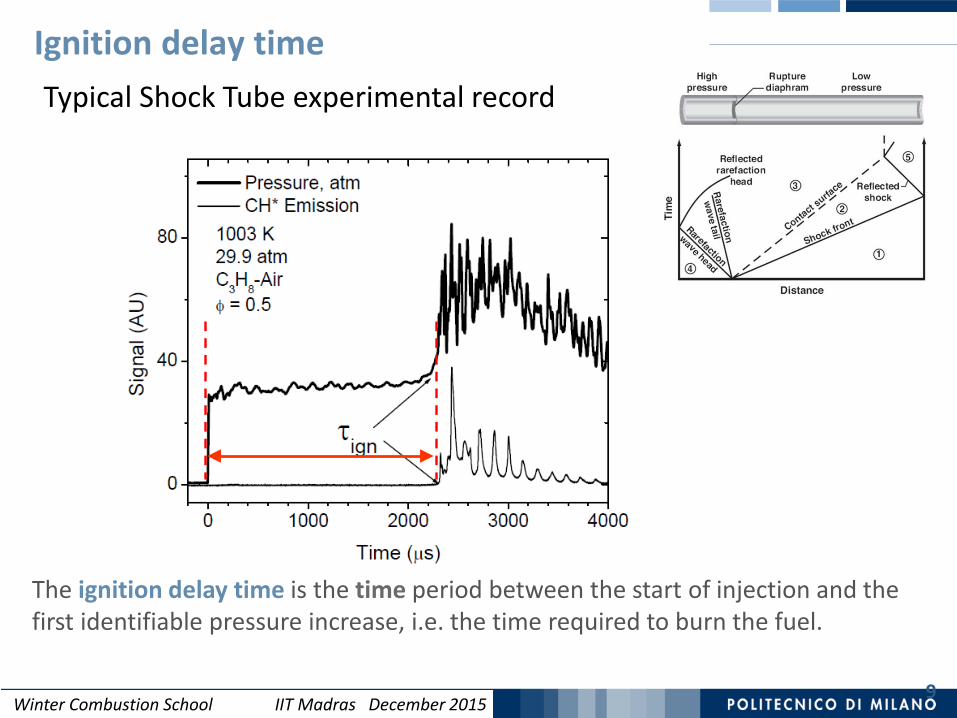
Ignition delay time
9
Typical Shock Tube experimental record
The ignition delay time is the time period between the start of injection and the first identifiable pressure increase, i.e. the time required to burn the fuel.

Winter Combustion School IIT Madras December 201510
Ignition delay times [µs] vs Temperature [K]
1
10
100
1000
5 6 7 810000/T [1/K]
CH4
C2H6
C3H8C4H10
High Temperature Combustion ProcessesCH4 and C2H6 show the lowest and the highest combustion rate.
Propane and butane have intermediate and similar reactivity.
CH4 ignites slowest because methyl radicals lead to chain termination. Ethane is most
reactive because every ethyl radical, resulting from H-atom abstraction, produces H atoms, thus promoting: H+O2 O + OH
1540 K
6 µs
300 µs

Winter Combustion School IIT Madras December 201511
Laminar Flame speed of CH4
Maximum flame speedat rich condition
Relevant effect of the initial temperature
36 cm/s
58 cm/s2
00
LTs sT
≈ ⋅
Winter Combustion School IIT Madras December 201512
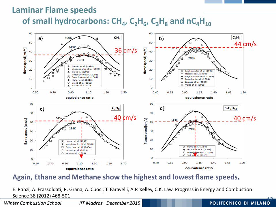
Laminar Flame speeds of small hydrocarbons: CH4, C2H6, C3H8 and nC4H10
Again, Ethane and Methane show the highest and lowest flame speeds.E. Ranzi, A. Frassoldati, R. Grana, A. Cuoci, T. Faravelli, A.P. Kelley, C.K. Law. Progress in Energy and Combustion Science 38 (2012) 468-501
44 cm/s36 cm/s
40 cm/s40 cm/s

Winter Combustion School IIT Madras December 2015
13
Laminar air-stoichiometric flames of small hydrocarbons (T0=298 K, P=1 atm).1- Predicted profiles of relevant radicals: H, CH3
Stoichiometric Flames of small hydrocarbons Hydrogen and Methyl radical concentration
Winter Combustion School IIT Madras December 2015
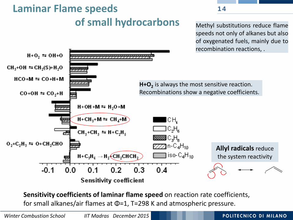
14Laminar Flame speeds of small hydrocarbons
Sensitivity coefficients of laminar flame speed on reaction rate coefficients, for small alkanes/air flames at Φ=1, T=298 K and atmospheric pressure.
Allyl radicals reduce the system reactivity
H+O2 is always the most sensitive reaction.Recombinations show a negative coefficients.
Methyl substitutions reduce flamespeeds not only of alkanes but alsoof oxygenated fuels, mainly due torecombination reactions, .
Winter Combustion School IIT Madras December 2015
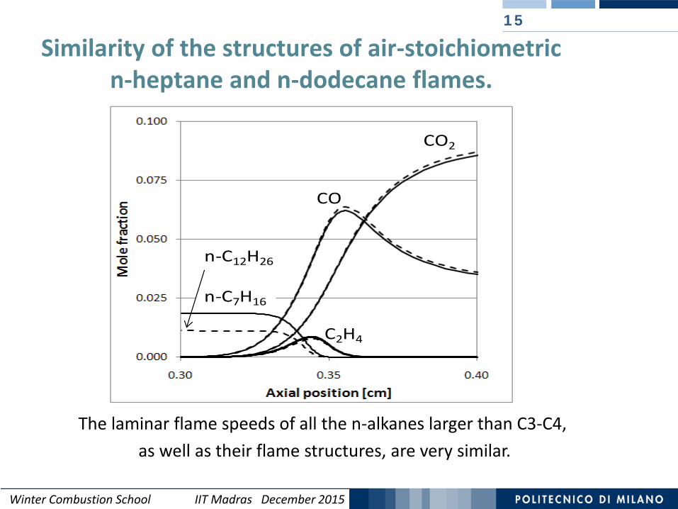
Similarity of the structures of air-stoichiometricn-heptane and n-dodecane flames.
15
CO2
C2H4
CO
n-C7H16
n-C12H26
The laminar flame speeds of all the n-alkanes larger than C3-C4, as well as their flame structures, are very similar.
Winter Combustion School IIT Madras December 2015
Methane Pyrolysis and Oxidation Reactions
CHi
O2
OH
Oxidation
CH3OOH
CH3OH
CH2OH
CH3OO
CH3
CH3O
CH2O
HCO
CO
CO2
C 2H 6
C 2H 5
C 2H 4
C 2H 3
C 2H 2
Aromatics
Soot
Pyrolysis
O2
CH4
NOx
Winter Combustion School IIT Madras December 2015
C2H4
C2H6
0
0.001
0.002
0.003
0 2e-06 4e-06 6e-06 8e-06 1e-05
C2H2
CO2
H2
O2
CH4
0
0.05
0.1
0.15
0.2
0.25
0 2e-06 4e-06 6e-06 8e-06 1e-05
H2O
CO
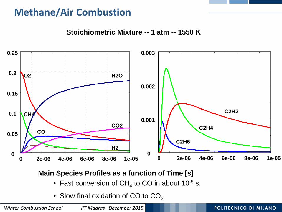
Stoichiometric Mixture -- 1 atm -- 1550 K
Main Species Profiles as a function of Time [s]• Fast conversion of CH4 to CO in about 10-5 s.
• Slow final oxidation of CO to CO2
Methane/Air Combustion

Winter Combustion School IIT Madras December 2015
NOx FormationNitric oxides are mainly formed from atmospheric N2 through three mechanisms:
Thermal, Prompt, and via N2O. The Thermal or Zel’dovich mechanism (1946) consists of three major reactions:
O· + N2 ↔ NO + N· k1f = 2·1014 exp(-75250/RT)N· + O2 ↔ NO + O· k2f = 6.4·109 exp(-6000/RT)N· + OH· ↔ NO + H· k3f = 3.8·1013
The concentration of O· and OH· radicals are ruled by combustion mechanism. Rate of NO formation is:
[ ] [ ][ ] [ ][ ] [ ][ ]OHNkONkNOkdtNOd
32221 ++=
The State State Approximation for N radicals gives:
By substituting [N], NO formation rate becomes:
[ ] [ ][ ] [ ] [ ] [ ]{ } 032221 ≅+−= OHkOkNNOkdtNd [ ] [ ][ ]
[ ] [ ]OHkOkNOkN322
21
+=
[ ] [ ][ ] [ ][ ] [ ][ ] [ ][ ]2132221 2 NOkOHNkONkNOkdtNOd
=++=
The first reaction is the rate controlling step: it requires the breaking of the tight N2bond and is favoured at high temperatures. The [O] concentration is obtained by usingthe partial equilibrium assumption for O2 ↔ 2 O
Winter Combustion School IIT Madras December 2015
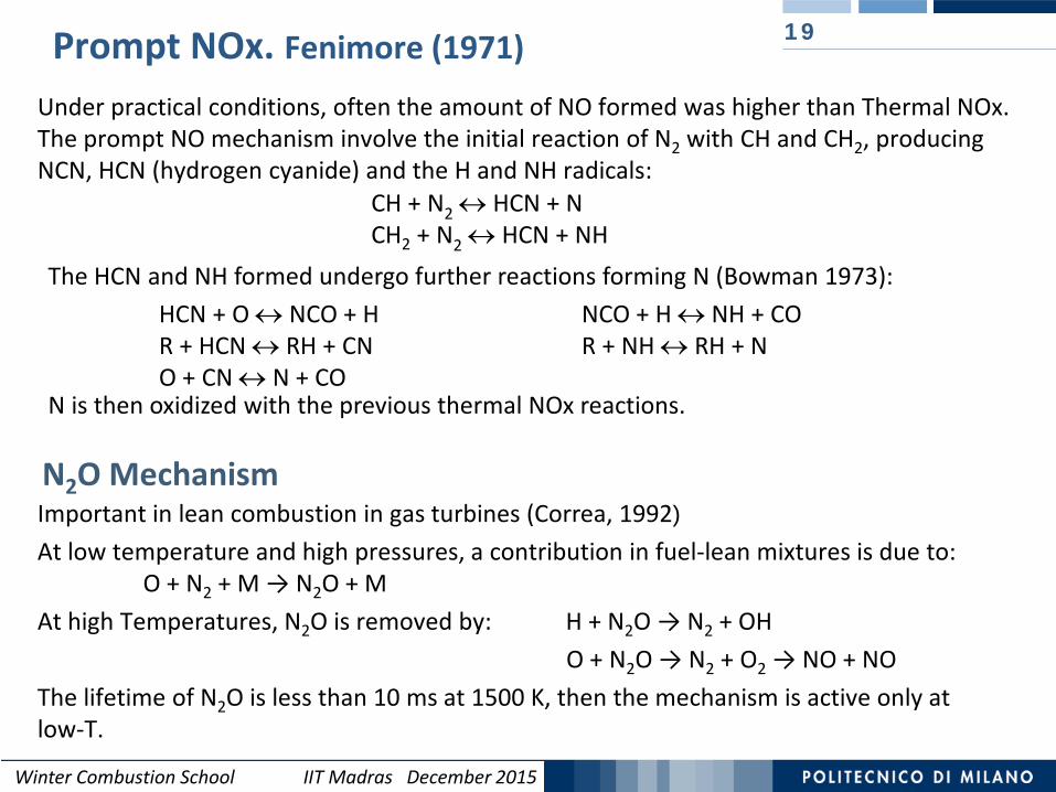
Prompt NOx. Fenimore (1971)
Under practical conditions, often the amount of NO formed was higher than Thermal NOx. The prompt NO mechanism involve the initial reaction of N2 with CH and CH2, producing NCN, HCN (hydrogen cyanide) and the H and NH radicals:
19
CH + N2 ↔ HCN + NCH2 + N2 ↔ HCN + NH
Important in lean combustion in gas turbines (Correa, 1992)At low temperature and high pressures, a contribution in fuel-lean mixtures is due to:
O + N2 + M → N2O + MAt high Temperatures, N2O is removed by: H + N2O → N2 + OH
O + N2O → N2 + O2 → NO + NOThe lifetime of N2O is less than 10 ms at 1500 K, then the mechanism is active only atlow-T.
N2O Mechanism
HCN + O ↔ NCO + H NCO + H ↔ NH + COR + HCN ↔ RH + CN R + NH ↔ RH + NO + CN ↔ N + CO
The HCN and NH formed undergo further reactions forming N (Bowman 1973):
N is then oxidized with the previous thermal NOx reactions.

Winter Combustion School IIT Madras December 2015
Prompt and Fuel NOxReburning Bowman [1973]
20
Major reaction steps in prompt NO formation.Reaction path diagram also illustrates the conversion of fuel nitrogen in flames, and reburning process.
Winter Combustion School IIT Madras December 2015
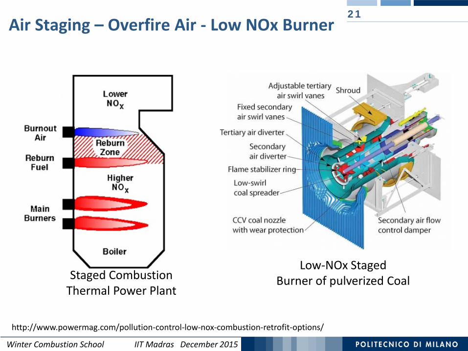
Air Staging – Overfire Air - Low NOx Burner21
http://www.powermag.com/pollution-control-low-nox-combustion-retrofit-options/
Low-NOx Staged Burner of pulverized CoalStaged Combustion
Thermal Power Plant
Winter Combustion School IIT Madras December 2015
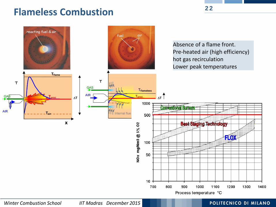
Flameless Combustion 22
Absence of a flame front.Pre-heated air (high efficiency)hot gas recirculationLower peak temperatures

Winter Combustion School IIT Madras December 2015
Combustion of Methane
2000 K C/O = 1/4 (stechiometrico)
Φ=1Effect of stoichiometryImportance of a ‘micro’ mixing
2000 K C/O = 1
Φ=4

Winter Combustion School IIT Madras December 2015
Oxygen CombustionProducts
Fuel
C
FUEL
AIR
Flame Front
Premixed Flame
Temperature and Concentration Profiles in
Fuel
Oxygen
AirAir
Fuel
Flame Front
Diffusive Flame
CombustionProducts
C
PyrolysisRich conditions
High T
Winter Combustion School IIT Madras December 2015
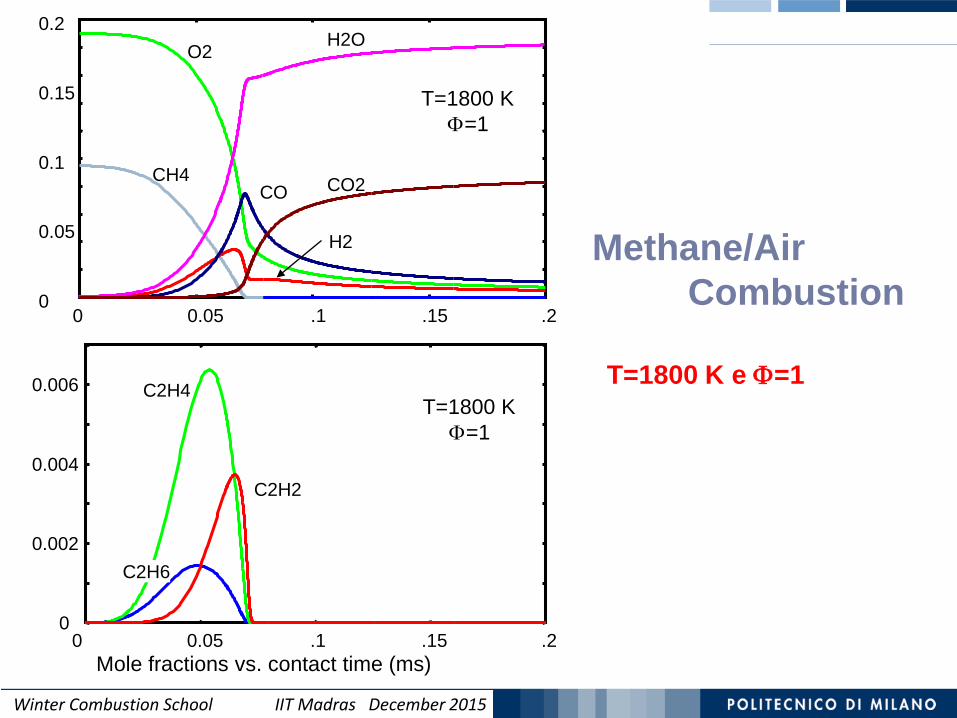
0
0.002
0.004
0.006
0 0.05 .1 .15 .2
C2H6
C2H4
C2H2
T=1800 KΦ=1
0
0.05
0.1
0.15
0.2
0 0.05 .1 .15 .2
CH4
O2 H2O
CO
H2
CO2
T=1800 KΦ=1
Methane/Air Combustion
T=1800 K e Φ=1
Mole fractions vs. contact time (ms)
Winter Combustion School IIT Madras December 2015
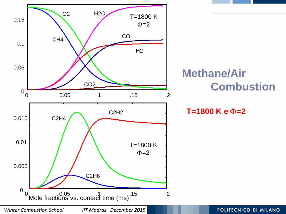
0
0.05
0.1
0.15
CH4
O2 H2O
CO
H2
CO2
0 0.05 .1 .15 .2
T=1800 KΦ=2
T=1800 KΦ=2
0
0.005
0.01
0.015
C2H6
C2H4C2H2
0 0.05 .1 .15 .2
Methane/Air Combustion
T=1800 K e Φ=2
Mole fractions vs. contact time (ms)
Winter Combustion School IIT Madras December 2015
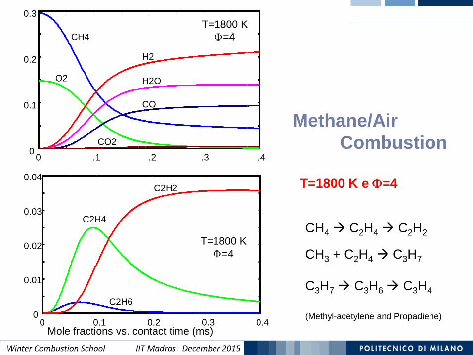
0
0.1
0.2
0.3
0 .1 .2 .3 .4
CH4
O2 H2O
CO
H2
CO2
T=1800 KΦ=4
0
0.01
0.02
0.03
0.04
0 0.1 0.2 0.3 0.4
C2H6
C2H4
C2H2
T=1800 KΦ=4
Methane/Air Combustion
T=1800 K e Φ=4
Mole fractions vs. contact time (ms)
CH4 C2H4 C2H2
CH3 + C2H4 C3H7
C3H7 C3H6 C3H4
(Methyl-acetylene and Propadiene)

Winter Combustion School IIT Madras December 2015
Propargyl Radicalsand First Aromatic Ring Formation
28
The dehydrogenation reaction of allene and methyl acetylene forms propargyl radicals:C3H4s C3H3+H
The very stable propargyl radicals can recombine to form C6H6 components:
Miller, J. A., & Klippenstein, S. J. (2003). The recombination of propargyl radicals and other reactions on a C6H6 potential. The Journal of Physical Chemistry A, 107(39), 7783-7799.
1,5-hexadiyne
Benzene
2 C3H3 C6H6
Fulvene

Winter Combustion School IIT Madras December 2015
29Propargyl Radicalsand First Aromatic Ring Formation
Miller, J. A., & Klippenstein, S. J. (2003). The recombination of propargyl radicals and other reactions on a C6H6 potential. The Journal of Physical Chemistry A, 107(39), 7783-7799.
2 C3H3 C6H6
Winter Combustion School IIT Madras December 2015
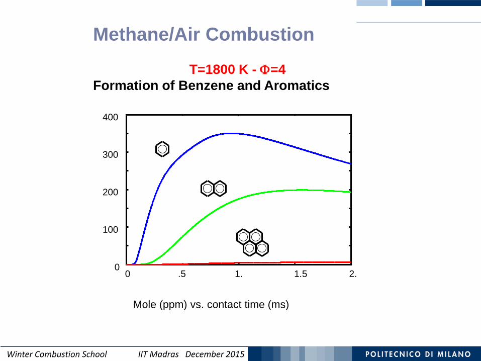
0
100
200
300
400
0 .5 1. 1.5 2.
Mole (ppm) vs. contact time (ms)
Methane/Air Combustion
T=1800 K - Φ=4Formation of Benzene and Aromatics

Winter Combustion School IIT Madras December 2015
Benzene and Pyrene (ppm) vs. Contact times (s)
0
200
400
600
0 0.005 0.01 0.015 0.02
1500 K
1600 K
1700 K
1800 K1900 K
0
2
4
6
8
10
12
0 0.005 0.01 0.015 0.02
1500 K
1600 K
1700 K
1800 K
1900 K
Methane
Combustion
Ф=4
Winter Combustion School IIT Madras December 2015
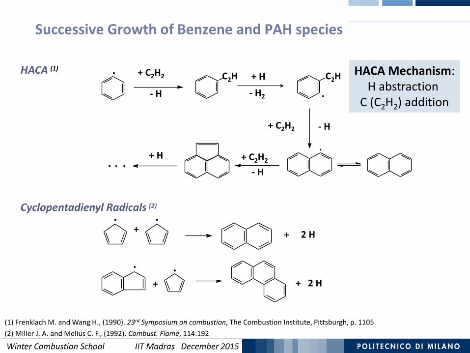
Successive Growth of Benzene and PAH species
+ + 2 H
+ 2 H+
Cyclopentadienyl Radicals (2)
(1) Frenklach M. and Wang H., (1990). 23rd Symposium on combustion, The Combustion Institute, Pittsburgh, p. 1105(2) Miller J. A. and Melius C. F., (1992). Combust. Flame, 114:192
- H
- H
- H
+ H- H2
+ H
+ C2H2 C2H C2H
+ C2H2
+ C2H2
HACA (1) HACA Mechanism:H abstraction
C (C2H2) addition

Winter Combustion School IIT Madras December 2015Winter Combustion School IIT Madras December 2015
Soot Formation in Combustion 33
CH CH3
CH2CH2
CHCH
CH2
CH
CH2CH
O2
COCO2
CH2
CH2
0 ms
1 ms
10 ms
100 ms
CH4
H. Bockhorn ‘Soot Formation in Combustion’ Springer-Verlag Berlin Heidelberg 1994
NucleationSoot Inception
Surface growth
Coagulation
100 nm
1 nm
Formation andGrowth of PAH
ParticleAggregation

Winter Combustion School IIT Madras December 2015
34
Low and High Temperature Reactions

Winter Combustion School IIT Madras December 2015
Low and High Temperature ReactionsAt high temperatures, the alkyl radical R decomposes, producing olefin and smaller alkyl
radicals. H+O2 O + OH is the dominant chain branching reaction.
35
At lower temperatures, alkyl radicals add to O2 forming Peroxy Radicals :R + O2 ↔ RO2
The equilibrium constant is strongly temperature dependent and is in favor of RO2at low T, shifting toward R + O2 as T increases.
The Ceiling Temperature is the temperature above which this equilibrium favors the dissociation path.
O•O H OOH•
Keto-/Carbonyl-hydroperoxides fastly decompose to form two radicals:
•OH +O
HOO
O
•O •OH +O
• + CH3CHO
Winter Combustion School IIT Madras December 2015
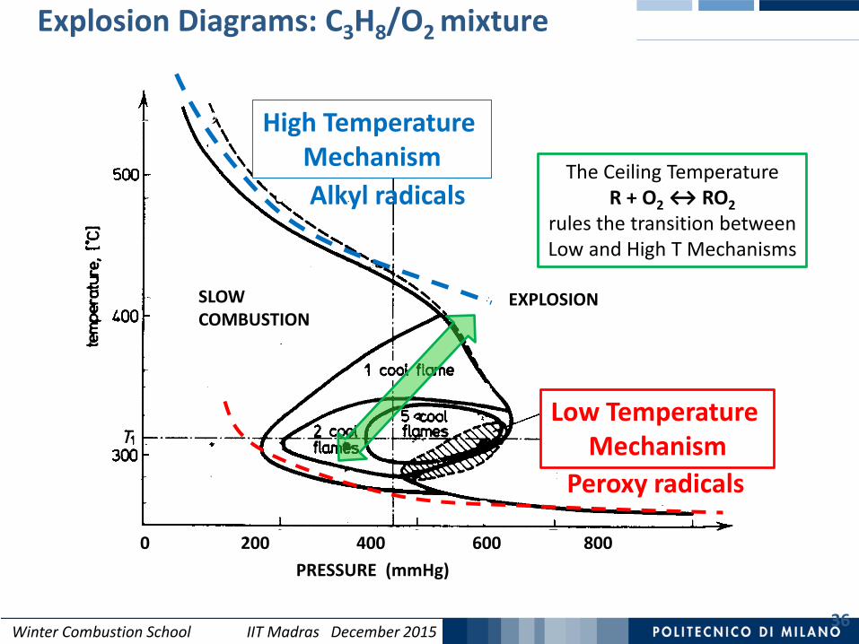
Explosion Diagrams: C3H8/O2 mixture
36
SLOW COMBUSTION
DELAYED TWO STAGEIGNITION
PRESSURE (mmHg)0 200 400 600 800
EXPLOSION
The Ceiling Temperature R + O2 ↔ RO2
rules the transition betweenLow and High T Mechanisms
Low Temperature Mechanism
Peroxy radicals
High Temperature MechanismAlkyl radicals
Winter Combustion School IIT Madras December 2015
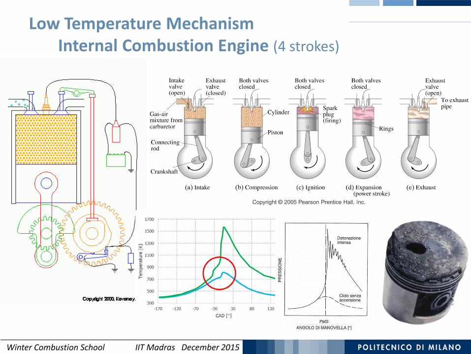
Low Temperature MechanismInternal Combustion Engine (4 strokes)
Winter Combustion School IIT Madras December 2015Winter Combustion School IIT Madras December 2015
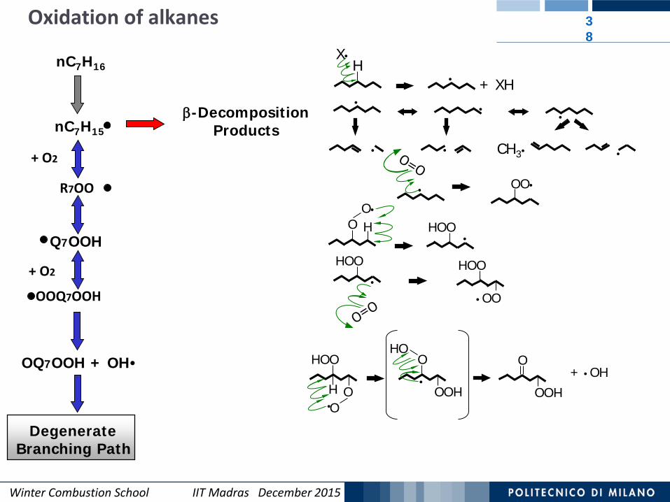
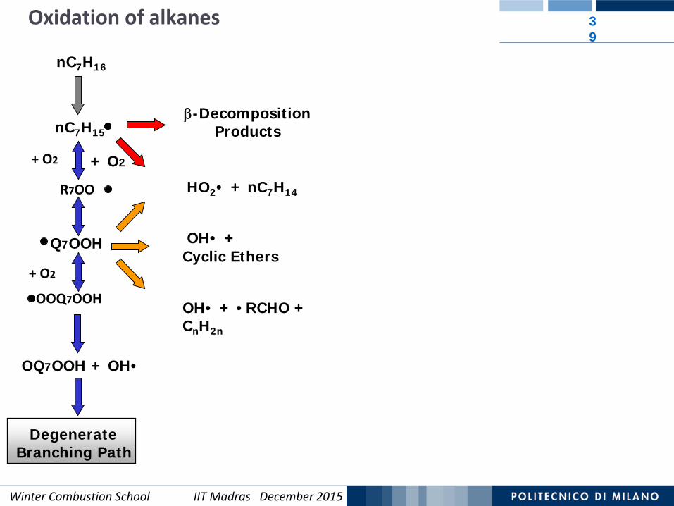
Oxidation of alkanes 38
nC7H16
+ O2
R7OO
nC7H15
Q7OOH
+ O2
OOQ7OOH
DegenerateBranching Path
•
• • CH3• •
••β-Decomposition
Products
+ XH•
X•H
• OO•
O•
O H HOO•
HOO•
HOO
•OO
OQ7OOH + OH• HOO
O•
OH
O
HOO•
HOO
HOO
+ •OH
Winter Combustion School IIT Madras December 2015Winter Combustion School IIT Madras December 2015
39
+ O2
OH• + Cyclic Ethers
OH• + •RCHO + CnH2n
HO2• + nC7H14
Oxidation of alkanes
nC7H16
+ O2
R7OO
nC7H15
Q7OOH
+ O2
OOQ7OOH
DegenerateBranching Path
β-Decomposition Products
OQ7OOH + OH•

Winter Combustion School IIT Madras December 2015Winter Combustion School IIT Madras December 2015
40
Low Temperature Mechanism
High Temperature Mechanism(Eapp ≅ 30000 cal/mol)
+ O2
OH• + Cyclic Ethers
OH• + •RCHO + CnH2n
HO2• + nC7H14
β-Decomposition Products
NTC
nC7H16
nC7H15
+ O2
R7OO
Q7OOH
+ O2
OOQ7OOH
DegenerateBranching Path
OQ7OOH + OH•
Oxidation of n-heptane in an Isothermal PFR
Chain Initiation Reactions [s-1]nC7H16 Products
C7H14O3 Products
1710 exp( 80000 )Fuelk RT−
1610 exp( 43000 )khpk RT−
conv
ersio
n
Reactor Temperature
Isothermal PFR
9 1010 10khp fuelk k ÷
at 800-900 K
Winter Combustion School IIT Madras December 2015Winter Combustion School IIT Madras December 2015
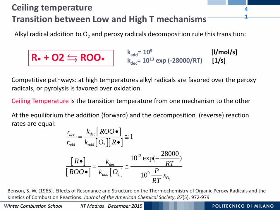
Ceiling temperatureTransition between Low and High T mechanisms
41
Alkyl radical addition to O2 and peroxy radicals decomposition rule this transition:
kadd= 109 [l/mol/s]kdec= 1013 exp (-28000/RT) [1/s]R● + O2 ROO●
Competitive pathways: at high temperatures alkyl radicals are favored over the peroxy radicals, or pyrolysis is favored over oxidation.
Ceiling Temperature is the transition temperature from one mechanism to the other
At the equilibrium the addition (forward) and the decomposition (reverse) reaction rates are equal:
[ ][ ][ ]
[ ][ ] [ ]
2
2
13
92
1
2800010 exp( )
10
decdec
add add
dec
addO
k ROOrr k O R
R k RTPROO k O x
RT
•= ≅
•
−•= ≅
•
Benson, S. W. (1965). Effects of Resonance and Structure on the Thermochemistry of Organic Peroxy Radicals and the Kinetics of Combustion Reactions. Journal of the American Chemical Society, 87(5), 972-979
Winter Combustion School IIT Madras December 2015Winter Combustion School IIT Madras December 2015
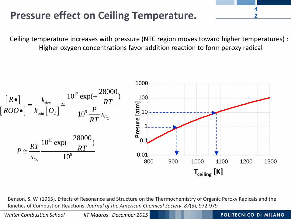
Pressure effect on Ceiling Temperature. 42
2
13
9
2800010 exp( )
10O
RT RTPx
−≅
[ ][ ] [ ]
2
13
92
2800010 exp( )
10dec
addO
R k RTPROO k O x
RT
−•= ≅
•
0.01
0.1
1
10
100
1000
800 900 1000 1100 1200 1300
Tceiling [K]
Pres
ure
[atm
]
Ceiling temperature increases with pressure (NTC region moves toward higher temperatures) : Higher oxygen concentrations favor addition reaction to form peroxy radical
Benson, S. W. (1965). Effects of Resonance and Structure on the Thermochemistry of Organic Peroxy Radicals and the Kinetics of Combustion Reactions. Journal of the American Chemical Society, 87(5), 972-979
Winter Combustion School IIT Madras December 2015Winter Combustion School IIT Madras December 2015
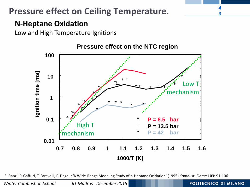
43
N-Heptane OxidationLow and High Temperature Ignitions
E. Ranzi, P. Gaffuri, T. Faravelli, P. Dagaut ‘A Wide-Range Modeling Study of n-Heptane Oxidation’ (1995) Combust. Flame 103: 91-106
0.01
0.1
1
10
100
0.7 0.8 0.9 1 1.1 1.2 1.3 1.4 1.5 1.6
igni
tion
time
[ms]
1000/T [K]
P = 6.5 barP = 13.5 barP = 42 bar
Pressure effect on the NTC region
Pressure effect on Ceiling Temperature.
Low T mechanism
High T mechanism
Winter Combustion School IIT Madras December 2015
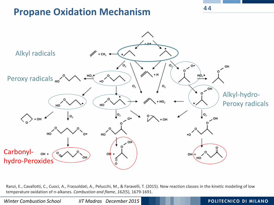
Propane Oxidation Mechanism 44
Ranzi, E., Cavallotti, C., Cuoci, A., Frassoldati, A., Pelucchi, M., & Faravelli, T. (2015). New reaction classes in the kinetic modeling of lowtemperature oxidation of n-alkanes. Combustion and flame, 162(5), 1679-1691.
Alkyl radicals
Peroxy radicals
Alkyl-hydro-Peroxy radicals
Carbonyl-hydro-Peroxides
Winter Combustion School IIT Madras December 2015
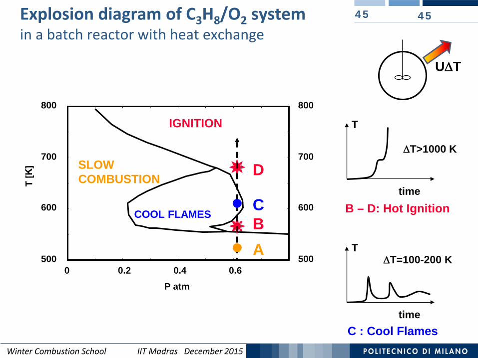
45Explosion diagram of C3H8/O2 systemin a batch reactor with heat exchange
45
500
600
700
800
0 0.2 0.4 0.6P atm
SLOW COMBUSTION
IGNITION
COOL FLAMES
500
600
700
800
A
time
T
∆T>1000 K
B – D: Hot IgnitionB
D
time
T∆T=100-200 K
C : Cool Flames
C
U∆T
Winter Combustion School IIT Madras December 2015
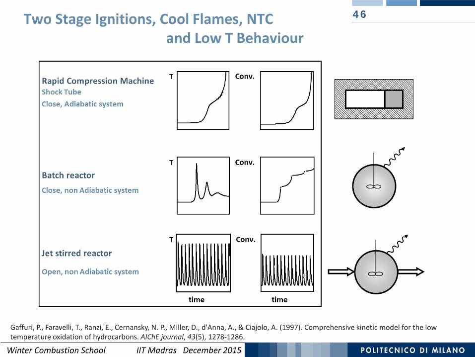
46Two Stage Ignitions, Cool Flames, NTC and Low T Behaviour
Gaffuri, P., Faravelli, T., Ranzi, E., Cernansky, N. P., Miller, D., d'Anna, A., & Ciajolo, A. (1997). Comprehensive kinetic model for the low temperature oxidation of hydrocarbons. AIChE journal, 43(5), 1278-1286.
Winter Combustion School IIT Madras December 2015
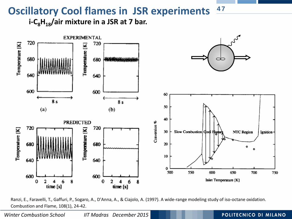
47Oscillatory Cool flames in JSR experimentsi-C8H18/air mixture in a JSR at 7 bar.
Ranzi, E., Faravelli, T., Gaffuri, P., Sogaro, A., D'Anna, A., & Ciajolo, A. (1997). A wide-range modeling study of iso-octane oxidation. Combustion and Flame, 108(1), 24-42.
Winter Combustion School IIT Madras December 2015
Outline 48
2.a Chemical Kinetics:Combustion of methane.Low and high temperature combustion of hydrocarbons.
2.b Reactions in Ideal Reactors with negligible molecular transport: plug flow and stirred reactors, shock tubes and rapid compression machines. Premixed and diffusion flames.
2.c PAH and soot formation.

Winter Combustion School IIT Madras December 2015
Reaction mechanisms are developed and validated with experiments in which fluid mixing is (almost) completely suppressed.
Reactors of this type include:- shock tubes, - turbulent flow reactors,- rapid compression machines.
Adapted from H. Wang , Princeton Summer School 2012
Degree of Mixing in Research Reactor
The degree and type of fluid mixing is an important feature in reacting flow simulation.
The mixing can occur among the reactants or between reactants and products.
Perfectly StirredReactor

Winter Combustion School IIT Madras December 2015
Ideal Chemical Reactors
Adapted from A. Cuoci, A. Frassoldati. COST- Milan Summer School 2013

Winter Combustion School IIT Madras December 2015
Rapid Compression Machine Shock Tube Jet Stirred Reactor
Experimental reactors and devices contribute to mechanism validation
Adapted from H. Curran, COST- Milan Summer School 2013
Flat Flame Burner
Counterflow burner Isolated Droplet in μg
Flow reactor
Winter Combustion School IIT Madras December 2015
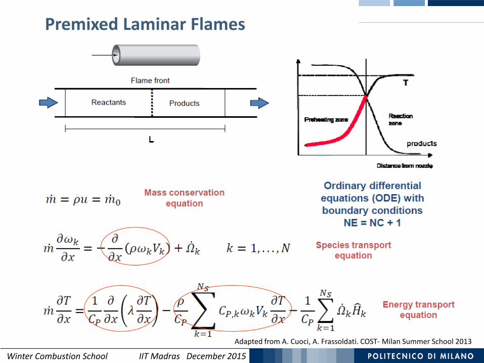
Premixed Laminar Flames
Adapted from A. Cuoci, A. Frassoldati. COST- Milan Summer School 2013

Winter Combustion School IIT Madras December 2015
Shock Tube Device 53
The available reaction time is limited to 0.1-5 ms by the arrival of the reflected waves.
Experimental facilities: Stanford University (CA); Galway University (Ireland);Rensselaer Polytechnic, Troy (NY) and UIC University of Illinois at Chicago (USA);KAUST, Saudi Arabia; IVG Duisburg and RWTH Aachen, Germany…. and others
A diaphragm initially separates a high and a low pressure region. Bursting the diaphragm, a shock wave is generated and propagates. It acts as a piston. The reactants at low T/p are instantly heated and pressurized to high values.
Winter Combustion School IIT Madras December 2015
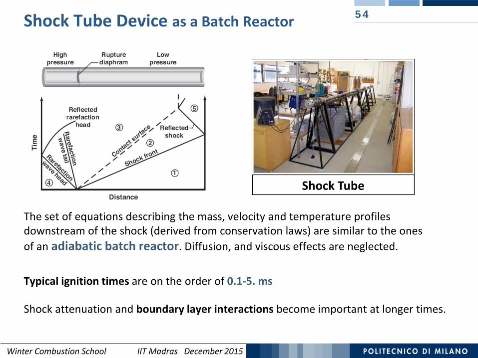
Shock Tube Device as a Batch Reactor
The set of equations describing the mass, velocity and temperature profiles downstream of the shock (derived from conservation laws) are similar to the ones of an adiabatic batch reactor. Diffusion, and viscous effects are neglected.
Typical ignition times are on the order of 0.1-5. ms
54
Shock Tube
Shock attenuation and boundary layer interactions become important at longer times.

Winter Combustion School IIT Madras December 2015Winter Combustion School IIT Madras December 2015
Typical results of Shock TubeIgnition Propensity of n-heptane and iso-octane
Fieweger et al, Combustion and Flame, 1997
% n-heptane
20
• At low temperatures the ignition behavior is stronglyfuel dependent
• High temperature kinetics isless sensitive to the fuelstructure
Octane Number (ON)Mix of Reference Fuels
Ignition delay times0.1-5. ms

Winter Combustion School IIT Madras December 2015
Ignition delay times of PRF
iso-octane
n-heptane
High Temperature Mechanism Low
Temperature Mechanism
Winter Combustion School IIT Madras December 2015
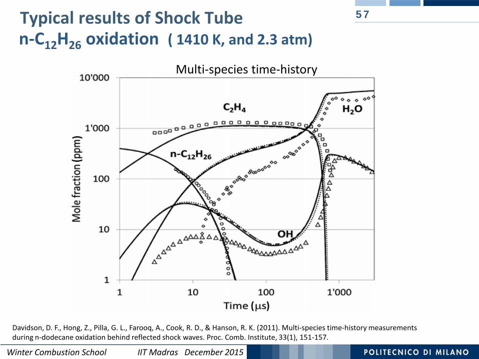
n-C12H26 oxidation ( 1410 K, and 2.3 atm)
57
Davidson, D. F., Hong, Z., Pilla, G. L., Farooq, A., Cook, R. D., & Hanson, R. K. (2011). Multi-species time-history measurementsduring n-dodecane oxidation behind reflected shock waves. Proc. Comb. Institute, 33(1), 151-157.
Multi-species time-history
Typical results of Shock Tube

Winter Combustion School IIT Madras December 2015
58
http://www1.eere.energy.gov/vehiclesandfuels/pdfs/merit_review_2011/adv_combustion/ace054_gupta_2011_o.pdf
The fuel-air mixture is initially contained in a chamber with one or two pistons forming the end walls. At t = 0, the pistons are driven into the chamber and the reactants are rapidly heated and compressed to high temperature and pressure.
Rapid Compression Machine (as Batch Reactor)

Winter Combustion School IIT Madras December 2015
This technique allows to determine the ignition delay times (10-300 ms), and the temporal variation of the ‘uniform’ mixture, temperature, and composition.
The system is supposed to reach the ideal conditions of a batch reactor.
Rapid Compression Machine (as Batch Reactor)
Galway University
Winter Combustion School IIT Madras December 2015
60
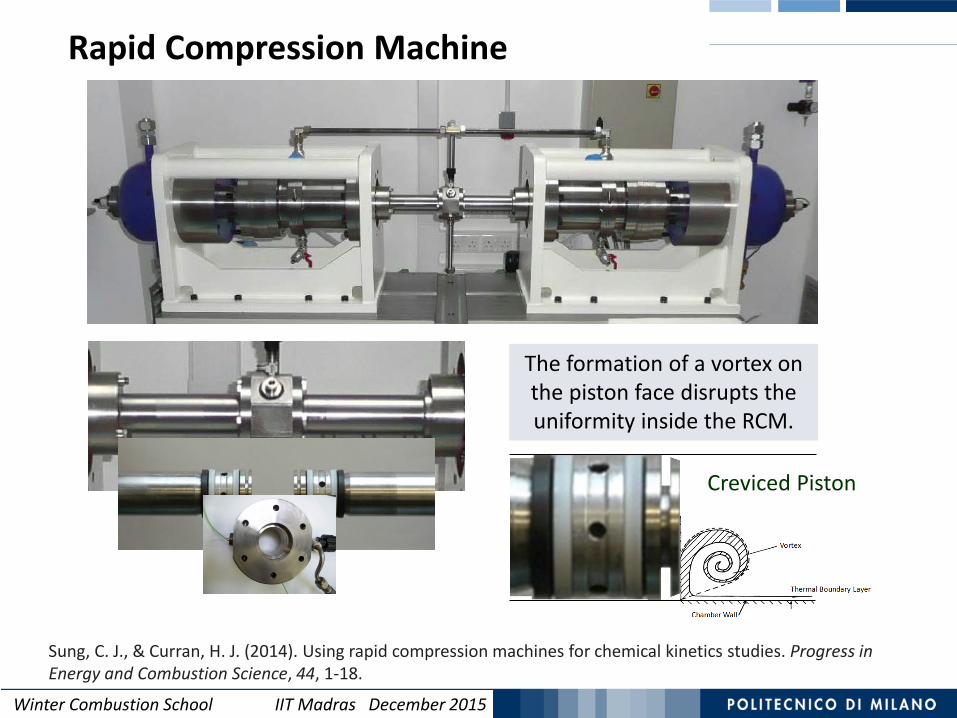
Rapid Compression Machine
Creviced Piston
The formation of a vortex on the piston face disrupts the uniformity inside the RCM.
Sung, C. J., & Curran, H. J. (2014). Using rapid compression machines for chemical kinetics studies. Progress in Energy and Combustion Science, 44, 1-18.
Winter Combustion School IIT Madras December 2015
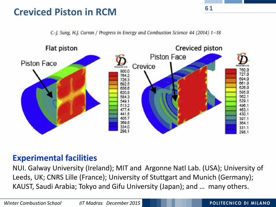
Creviced Piston in RCM 61
Experimental facilitiesNUI. Galway University (Ireland); MIT and Argonne Natl Lab. (USA); University of Leeds, UK; CNRS Lille (France); University of Stuttgart and Munich (Germany); KAUST, Saudi Arabia; Tokyo and Gifu University (Japan); and … many others.

Winter Combustion School IIT Madras December 2015
Are Shock Tube and RCM Ideal Batch Reactors?
62
Ignition delay time data at high pressure and low temperatures are of interest mainly for the validation of kinetic mechanisms at practical engine conditions.
Propane ignition delay time measurements with ST and RCM at 20-40 atm
Sung, C. J., & Curran, H. J. (2014). Using rapid compression machines for chemical kinetics studies. Progress in Energy and Combustion Science, 44, 1-18.
RCM
ST
RCM and Shock Tube (ST) data can disagree at high pressures and T < 1100 K (and high τ). Ignition delay times obtained from ST are faster than those from RCM
(and model predictions).Moreover, data from different RCMs can also disagree for different ‘facility effects’.
Winter Combustion School IIT Madras December 2015
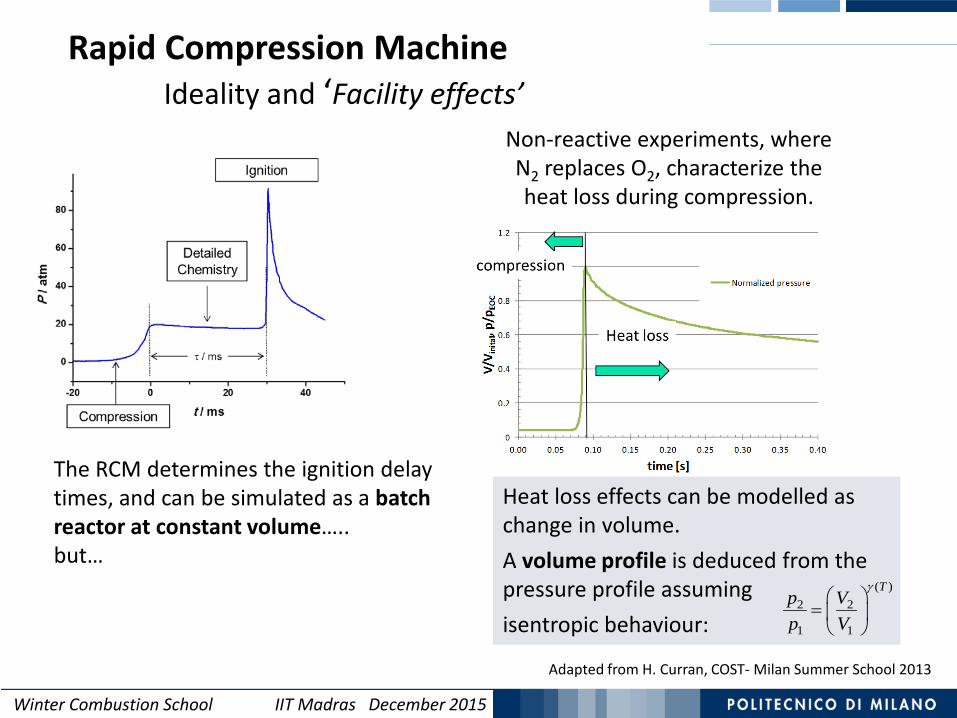
Non-reactive experiments, where N2 replaces O2, characterize the heat loss during compression.
Heat loss effects can be modelled as change in volume. A volume profile is deduced from the pressure profile assuming isentropic behaviour:
( )2 2
1 1
Tp Vp V
γ
=
Rapid Compression MachineIdeality and ‘Facility effects’
The RCM determines the ignition delay times, and can be simulated as a batch reactor at constant volume…..but…
Adapted from H. Curran, COST- Milan Summer School 2013
Winter Combustion School IIT Madras December 2015
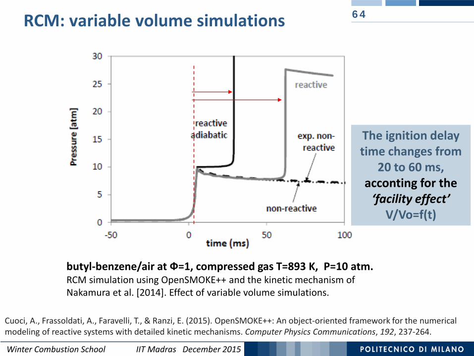
RCM: variable volume simulations 64
butyl-benzene/air at Ф=1, compressed gas T=893 K, P=10 atm.RCM simulation using OpenSMOKE++ and the kinetic mechanism of Nakamura et al. [2014]. Effect of variable volume simulations.
Cuoci, A., Frassoldati, A., Faravelli, T., & Ranzi, E. (2015). OpenSMOKE++: An object-oriented framework for the numerical modeling of reactive systems with detailed kinetic mechanisms. Computer Physics Communications, 192, 237-264.
The ignition delay time changes from
20 to 60 ms, acconting for the
‘facility effect’V/Vo=f(t)
Winter Combustion School IIT Madras December 2015
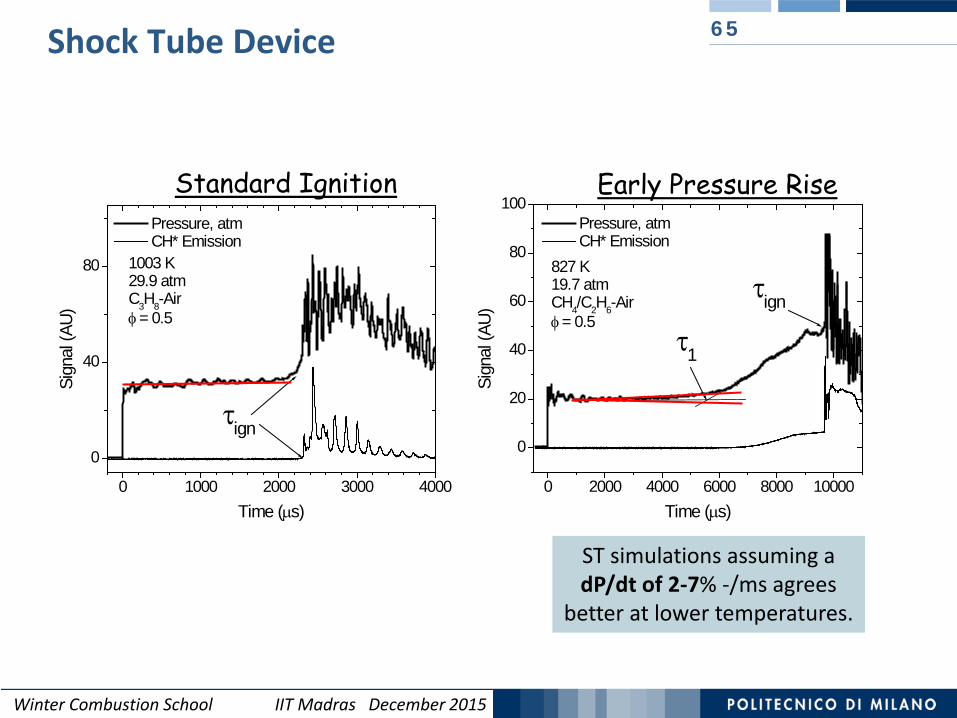
65Shock Tube Device
0 1000 2000 3000 4000
0
40
80
τign
1003 K29.9 atmC3H8-Air φ = 0.5
Sign
al (A
U)
Time (µs)
Pressure, atm CH* Emission
Standard Ignition
0 2000 4000 6000 8000 10000
0
20
40
60
80
100
τign
τ1
827 K19.7 atmCH4/C2H6-Air φ = 0.5
Sign
al (A
U)Time (µs)
Pressure, atm CH* Emission
Early Pressure Rise
ST simulations assuming a dP/dt of 2-7% -/ms agrees
better at lower temperatures.

Winter Combustion School IIT Madras December 2015
N2
Ar
66Shock Tube Device (simulation using dP/dt)
Propane ignition delay time measurements at low temperatures and high pressures for fuel in ‘air’ mixtures at Ф=0.5, PC=30 atm, - in N2 and Ar, and comparison with a traditional constant energy and volume (or density) simulation and with a simulation using dP/dt =7% [-/ms].
Sung, C. J., & Curran, H. J. (2014). Using rapid compression machines for chemical kinetics studies. Progress in Energy and Combustion Science, 44, 1-18.
At temperatures below 1100 K, the predicted ignition delay times using an adiabatic, constant volume simulation are slower than experiments. Simulations assuming a dP/dt of 7%/ms agrees better at the lower temperatures.
Winter Combustion School IIT Madras December 2015
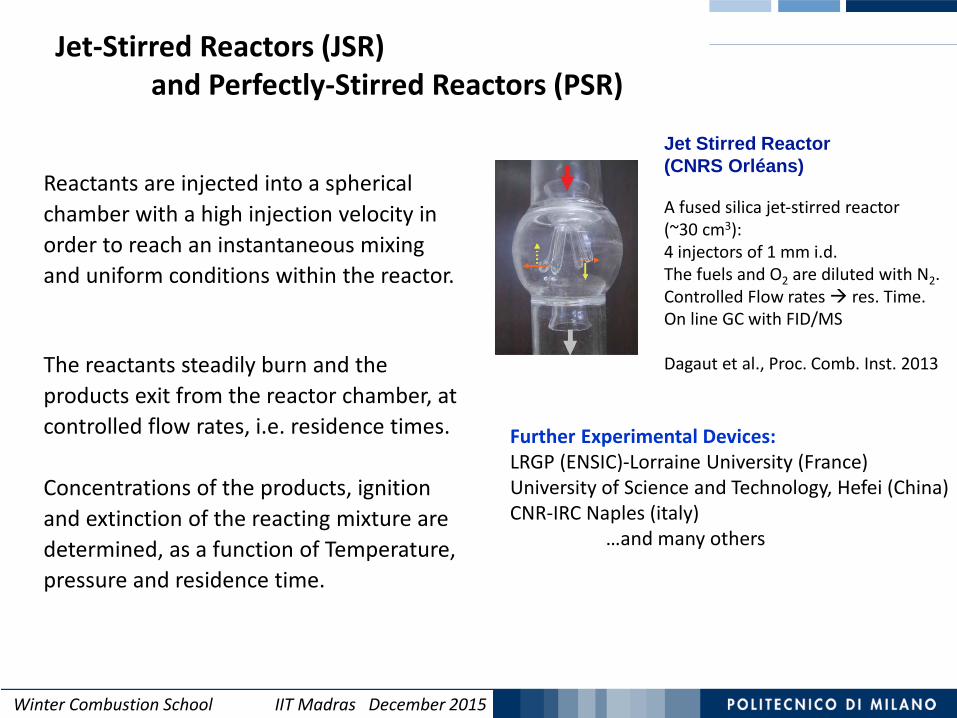
The reactants steadily burn and the products exit from the reactor chamber, at controlled flow rates, i.e. residence times.
Concentrations of the products, ignition and extinction of the reacting mixture are determined, as a function of Temperature, pressure and residence time.
Jet-Stirred Reactors (JSR) and Perfectly-Stirred Reactors (PSR)
Jet Stirred Reactor (CNRS Orléans)
A fused silica jet-stirred reactor (~30 cm3):4 injectors of 1 mm i.d.The fuels and O2 are diluted with N2. Controlled Flow rates res. Time.On line GC with FID/MS
Dagaut et al., Proc. Comb. Inst. 2013
Further Experimental Devices:LRGP (ENSIC)-Lorraine University (France)University of Science and Technology, Hefei (China)CNR-IRC Naples (italy)
…and many others
Reactants are injected into a spherical chamber with a high injection velocity in order to reach an instantaneous mixing and uniform conditions within the reactor.

Winter Combustion School IIT Madras December 2015
JSR CNRS OrleansOxidation of butanol− n-heptane mixtures
68
Dagaut, P., & Togbe ́, C. (2009). Experimental and modeling study of the kinetics of oxidation of butanol− n-heptane mixtures in a jet-stirred reactor. Energy & Fuels, 23(7), 3527-3535.
Winter Combustion School IIT Madras December 2015
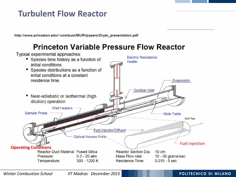
Turbulent Flow Reactor
Fuel injectionOperating Conditions

Winter Combustion School IIT Madras December 2015
70
http://www.princeton.edu/~combust/MURI/papers/Dryer_presentation.pdf
Ideal Plug Flow Reactor Assumption

Winter Combustion School IIT Madras December 2015
71Initial Mixing effect on the overall reaction time
tot PSR PFRτ τ τ= +
2276 ppm CH4, 3.69% O2, 4% H2O in N2T=1165 K
At different 𝜏𝜏𝑃𝑃𝑃𝑃𝑃𝑃, the CO profiles, can be overlayedidentically by time shifting.
Dryer, F. L., Haas, F. M., Santner, J., Farouk, T. I., & Chaos, M. (2014). Interpreting chemical kinetics from complex reaction–advection–diffusion systems: Modeling of flow reactors and related experiments. Progress in Energy and Combustion Science, 44, 19-39.
The overall residence time in the PFR isreduced to account for a residence time inside the mixing zone (PSR):
In absence of reactions in the mixing zone a simple time shifting is
sufficient to compare model predictions and experiments.
Winter Combustion School IIT Madras December 2015
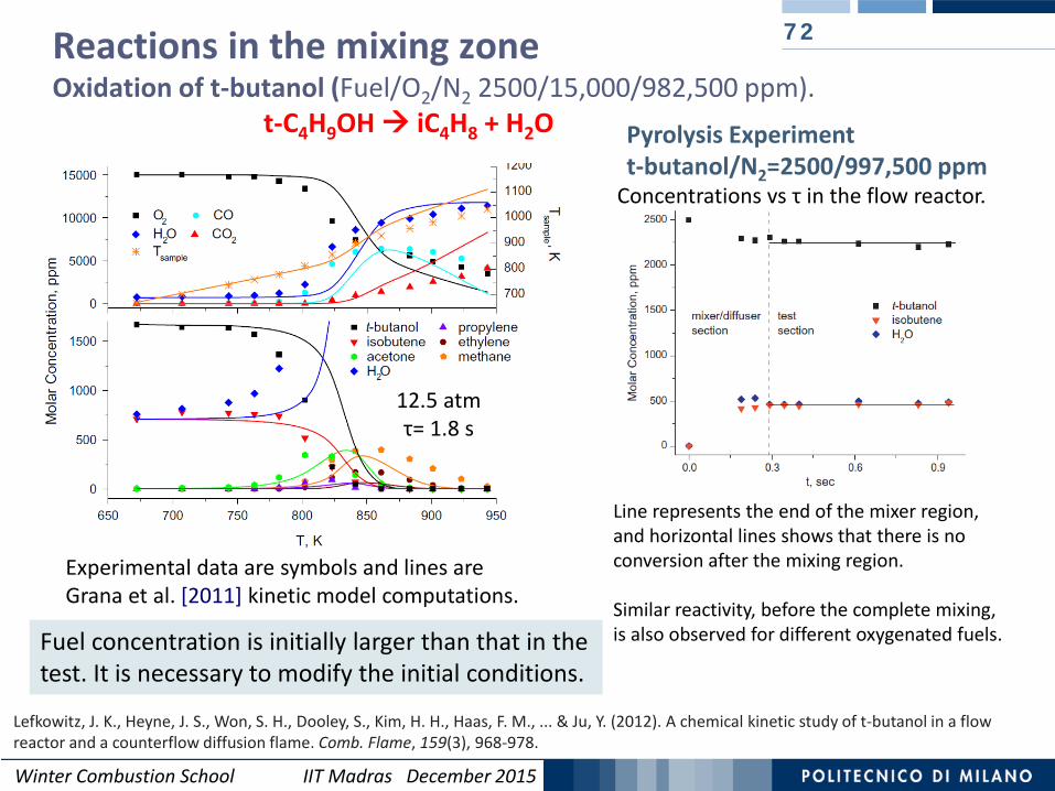
Reactions in the mixing zoneOxidation of t-butanol (Fuel/O2/N2 2500/15,000/982,500 ppm).
t-C4H9OH iC4H8 + H2O
72
Lefkowitz, J. K., Heyne, J. S., Won, S. H., Dooley, S., Kim, H. H., Haas, F. M., ... & Ju, Y. (2012). A chemical kinetic study of t-butanol in a flow reactor and a counterflow diffusion flame. Comb. Flame, 159(3), 968-978.
Experimental data are symbols and lines are Grana et al. [2011] kinetic model computations.
Fuel concentration is initially larger than that in the test. It is necessary to modify the initial conditions.
12.5 atmτ= 1.8 s
Line represents the end of the mixer region, and horizontal lines shows that there is no conversion after the mixing region.
Similar reactivity, before the complete mixing, is also observed for different oxygenated fuels.
Pyrolysis Experimentt-butanol/N2=2500/997,500 ppm
Concentrations vs τ in the flow reactor.
Winter Combustion School IIT Madras December 2015
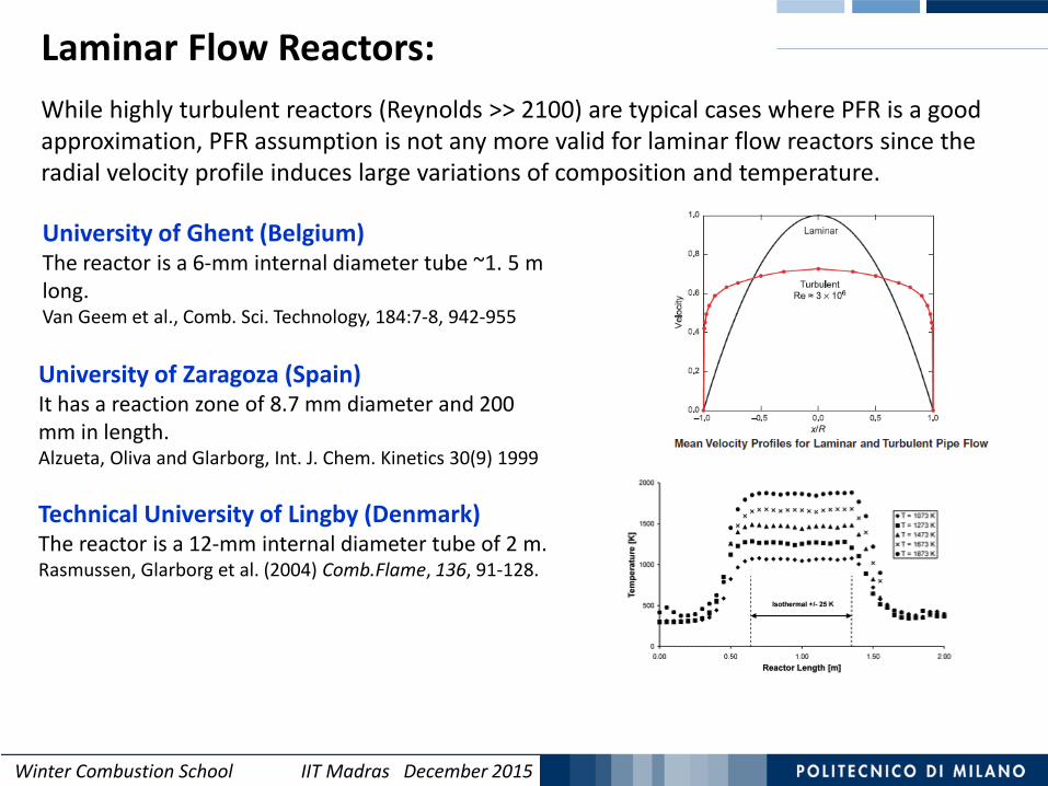
University of Ghent (Belgium)The reactor is a 6-mm internal diameter tube ~1. 5 m long.Van Geem et al., Comb. Sci. Technology, 184:7-8, 942-955
While highly turbulent reactors (Reynolds >> 2100) are typical cases where PFR is a good approximation, PFR assumption is not any more valid for laminar flow reactors since the radial velocity profile induces large variations of composition and temperature.
University of Zaragoza (Spain)It has a reaction zone of 8.7 mm diameter and 200 mm in length. Alzueta, Oliva and Glarborg, Int. J. Chem. Kinetics 30(9) 1999
Technical University of Lingby (Denmark)The reactor is a 12-mm internal diameter tube of 2 m.Rasmussen, Glarborg et al. (2004) Comb.Flame, 136, 91-128.
Laminar Flow Reactors:
Winter Combustion School IIT Madras December 2015
Laminar Flow Reactors 74
αβ
χ ββ
∞ −
= − ∫Ae d3
1
1 2 00
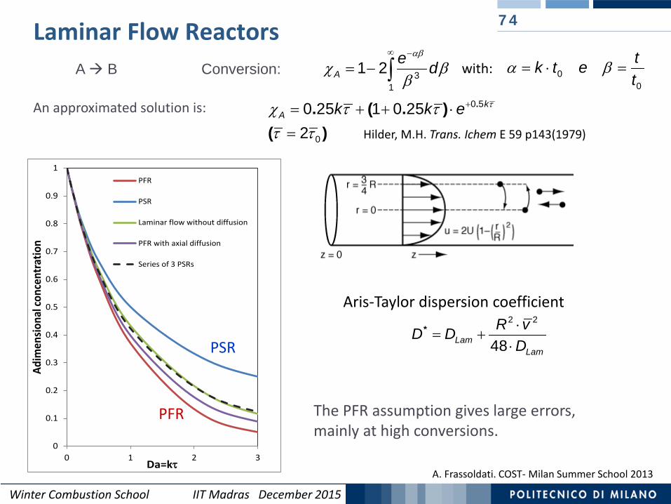
α β= ⋅ =tk t et
with:A B Conversion:
An approximated solution is:
Aris-Taylor dispersion coefficient⋅
= +⋅
*Lam
Lam
R vD DD
2 2
48
Hilder, M.H. Trans. Ichem E 59 p143(1979)
τχ τ ττ τ
+= + + ⋅=
.. ( . )( )
kA k k e 0 5
0
0 25 1 0 252
The PFR assumption gives large errors, mainly at high conversions.
A. Frassoldati. COST- Milan Summer School 2013
0
0.1
0.2
0.3
0.4
0.5
0.6
0.7
0.8
0.9
1
0 1 2 3
Adim
ensio
nal c
once
ntra
tion
Da=kτ
PFR
PSR
Laminar flow without diffusion
PFR with axial diffusion
Series of 3 PSRs
PFR
PSR
Winter Combustion School IIT Madras December 2015
A. Frassoldati. COST- Milan Summer School 2013
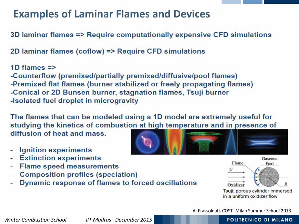
Examples of Laminar Flames and Devices
Winter Combustion School IIT Madras December 2015
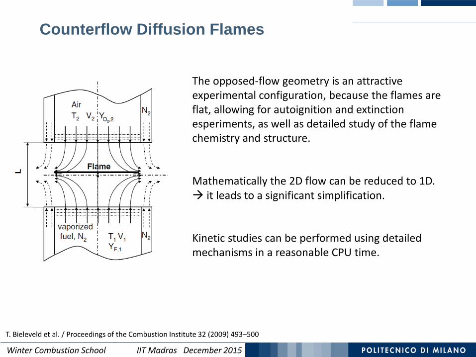
The opposed-flow geometry is an attractive experimental configuration, because the flames are flat, allowing for autoignition and extinction esperiments, as well as detailed study of the flame chemistry and structure.
Mathematically the 2D flow can be reduced to 1D. it leads to a significant simplification.
Kinetic studies can be performed using detailed mechanisms in a reasonable CPU time.
Counterflow Diffusion Flames
T. Bieleveld et al. / Proceedings of the Combustion Institute 32 (2009) 493–500
Winter Combustion School IIT Madras December 2015
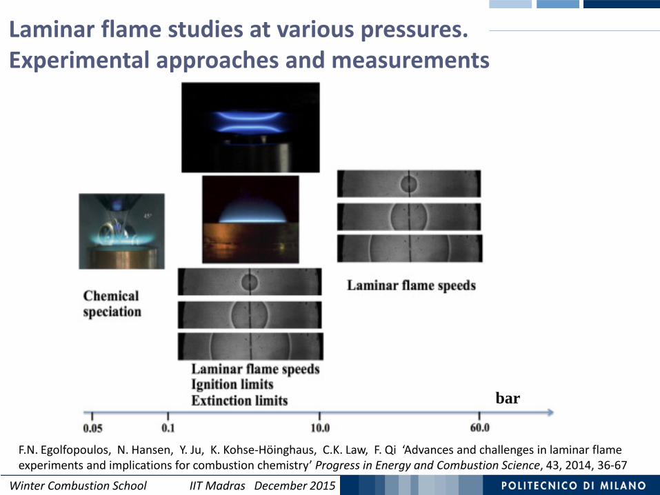
F.N. Egolfopoulos, N. Hansen, Y. Ju, K. Kohse-Höinghaus, C.K. Law, F. Qi ‘Advances and challenges in laminar flame experiments and implications for combustion chemistry’ Progress in Energy and Combustion Science, 43, 2014, 36-67
bar
Laminar flame studies at various pressures. Experimental approaches and measurements

Winter Combustion School IIT Madras December 2015
78
Ignition delay time
Concentration–time profile
Laminar burning velocity
Rapid compression machine (RCM)
Shock tube
Flow reactor
Jet-stirred reactor (JSR)
Bunsen burner (flame cone method)Counterflow twin-flame configuration
Heat flux burner
Adiabatic system with the volume as a function of time
Adiabatic system withconstant volume
Steady, laminar, one-dimensional premixed flame
Perfectly stirred reactor(spatially homogeneous mixture)
SENKIN
PSR
PREMIXOpenSMOKE
MEASUREMENT FACILITY MODELING APPROACH SOLVER
Ideal Experimental Systems and Simulation framework
Courtesy of Carsten Olm (2015) Eotvos University. Budapest. Hungary

Winter Combustion School IIT Madras December 2015
Outline 79
Chemical Kinetics:Combustion of methane.Low and high temperature combustion of
hydrocarbons.
Reactions in ideal reactors with negligible molecular transport: plug flow and stirred reactors, shock tubes and rapid compression machines. Premixed and diffusion flames.
PAH and Soot formation.
Winter Combustion School IIT Madras December 2015
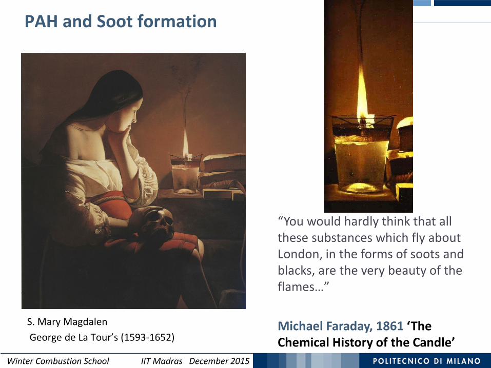
PAH and Soot formation 80
S. Mary MagdalenGeorge de La Tour’s (1593-1652)
“You would hardly think that all these substances which fly about London, in the forms of soots and blacks, are the very beauty of the flames…”
Michael Faraday, 1861 ‘The Chemical History of the Candle’

Winter Combustion School IIT Madras December 2015
Soot emissions Combustion is the main source of PAH and Soot or Particulate Matter (PM). On-road and non-road diesel engines are leading emitters (about 70%) in Europe,
North America, and Latin America. Soot forms at high temperatures and rich conditions (it also lowers the efficiency).
Global BC Emissions in 2000by region and source
T.C. Bond, E. Bhardwaj, R. Dong, et al., Global Biogeochem. Cy. 21 (2007).
BC emissions (Gg)T.C. Bond, S.J. Doherty, D.W. Fahey, et al., J. Geophys.
Res-Atmos. 118 (2013) 5380-5552.
81
Winter Combustion School IIT Madras December 2015
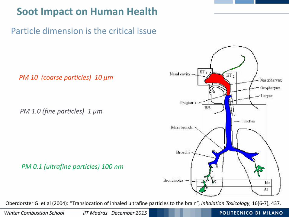
PM 10 (coarse particles) 10 μm
PM 1.0 (fine particles) 1 μm
PM 0.1 (ultrafine particles) 100 nm
Particle dimension is the critical issue
Oberdorster G. et al (2004): “Translocation of inhaled ultrafine particles to the brain”, Inhalation Toxicology, 16(6-7), 437.
Soot Impact on Human Health
Winter Combustion School IIT Madras December 2015
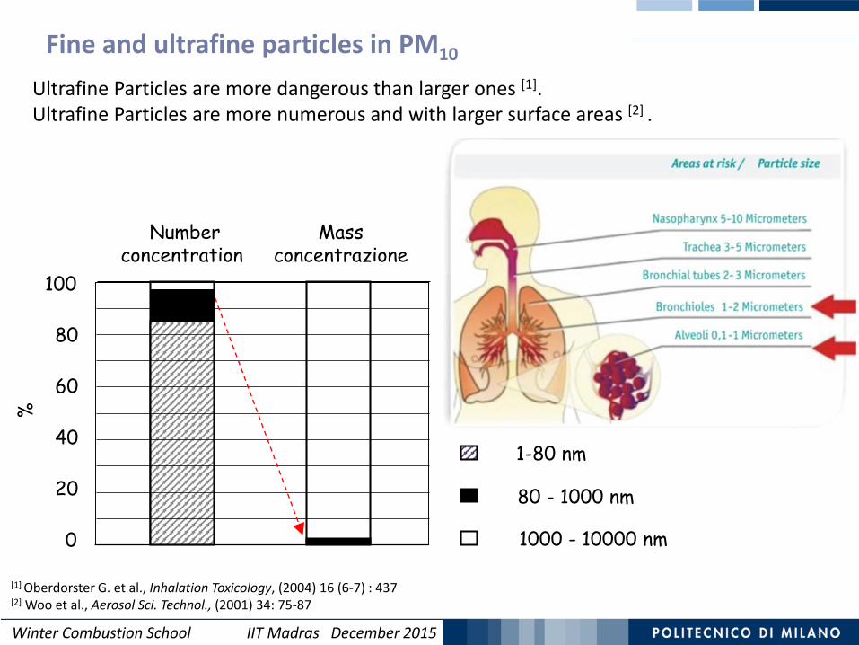
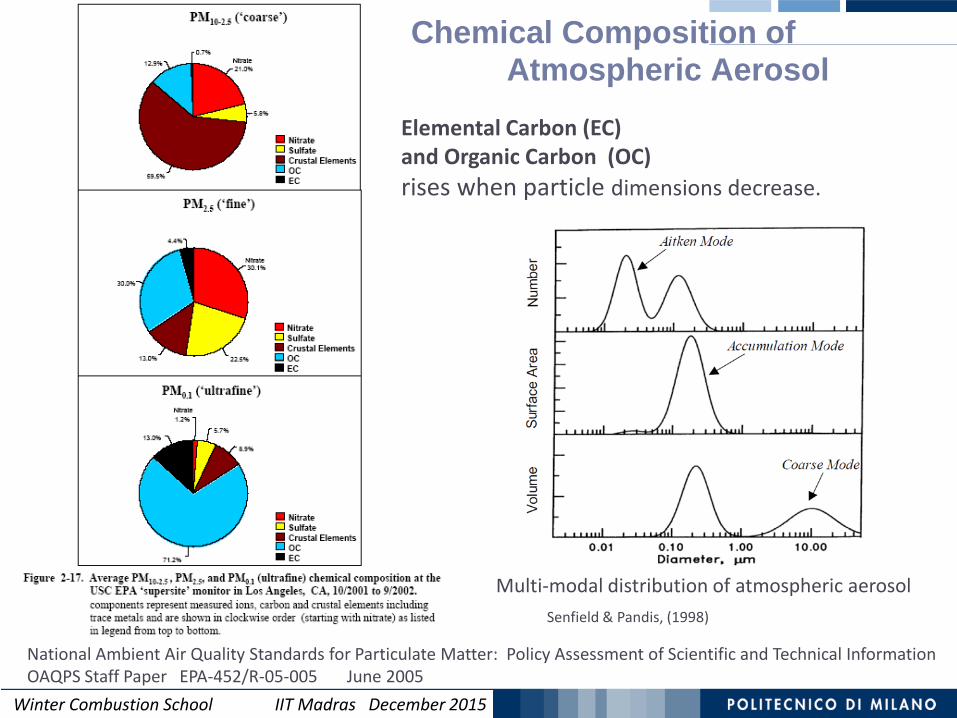
1-80 nm
80 - 1000 nm
1000 - 10000 nm
Numberconcentration
Mass concentrazione
80
60
100
20
40
0
%Fine and ultrafine particles in PM10
Ultrafine Particles are more dangerous than larger ones [1]. Ultrafine Particles are more numerous and with larger surface areas [2] .
[1] Oberdorster G. et al., Inhalation Toxicology, (2004) 16 (6-7) : 437[2] Woo et al., Aerosol Sci. Technol., (2001) 34: 75-87
Winter Combustion School IIT Madras December 2015
Elemental Carbon (EC) and Organic Carbon (OC)rises when particle dimensions decrease.
Chemical Composition of Atmospheric Aerosol
National Ambient Air Quality Standards for Particulate Matter: Policy Assessment of Scientific and Technical Information OAQPS Staff Paper EPA-452/R-05-005 June 2005
Senfield & Pandis, (1998)
Multi-modal distribution of atmospheric aerosol

Winter Combustion School IIT Madras December 2015Winter Combustion School IIT Madras December 2015
Soot Formation in Combustion 85
CH CH3
CH2CH2
CHCH
CH2
CH
CH2CH
O2
COCO2
CH2
CH2
0 ms
1 ms
10 ms
100 ms
CH4
H. Bockhorn ‘Soot Formation in Combustion’ Springer-Verlag Berlin Heidelberg 1994
NucleationSoot Inception
Surface growth
Coagulation
100 nm
1 nm
Formation andGrowth of PAH
ParticleAggregation

Winter Combustion School IIT Madras December 2015
Growing Mechanisms of PAH
- H
- H
- H+ H- H2
+ H
+ C2H2 C2H C2H
+ C2H2
+ C2H2
HACA (1)
+ + 2 H
+ 2 H+
Resonantly Stabilized Radicals (2)
(1) Frenklach M. and Wang H., (1990). 23rd Symposium on combustion, The Combustion Institute, Pittsburgh, p. 1105(2) Miller J. A. and Melius C. F., (1992). Combust. Flame, 114:192

Winter Combustion School IIT Madras December 2015
0.0
0.2
0.4
0.6
0.8
1.0
1.2
1 2 3 4 5 6log MW
H/C
CHCH
CH
CHPAHs
Soot Molecular Weight and H/C ratio
aromers tar
Soot
A.D’Anna (2004) Università ‘Federico ii’ Napoli adapted from:
Growing Mechanisms of PAH and Soot

Winter Combustion School IIT Madras December 2015
Soot: Primary particles ~ 20nm, and aggregate ~ 500nm
(Laminar Diffusion Flame, Dobbins RA & Megaridis)
A.Sarofim. ‘The Dark and Light Sides of Soot: Impacts on Human Health, Luminous Radiation, and Global Climate’ NIST (2003)
Soot Microstructure and SEM imagine of a Soot Aggregate
Soot Microstructure.
Soot: Primary particle ~ 20nm
Basic Structural Unit
~ 0.35nm between the different layers
Winter Combustion School IIT Madras December 2015
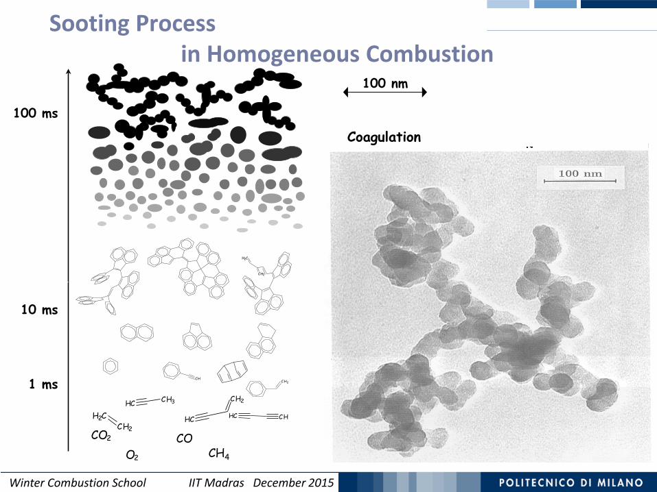
Sooting Processin Homogeneous Combustion
1 ms
10 ms
100 ms
C H2CH
CH2
CH2
CH CH3
CH2CH2
CHCH
CH2
CH
O2
COCO2
CH4
Formation andGrowth of PAH
1 nm
Combustion
Particle inception
Surface Growth
Coagulation
100 nm

Winter Combustion School IIT Madras December 2015Winter Combustion School IIT Madras December 2015
90
C2H4
C2H3
C2H2
CH2CHO
CH2COHCCO
pC3H4
C3H3 C6H6
C6H5C6H5O
C6H5C2H
C6H4C2H C10H7 C12H8 C14H10 C16H10 SOOT
PAH Formation in Ethylene Flames
Then HACA mechanism (C2H2) is the main responsible
for Soot formation.
HACA mechanism
Benzene and acetylene are the main intermediates in the first PAH formation.
Winter Combustion School IIT Madras December 2015
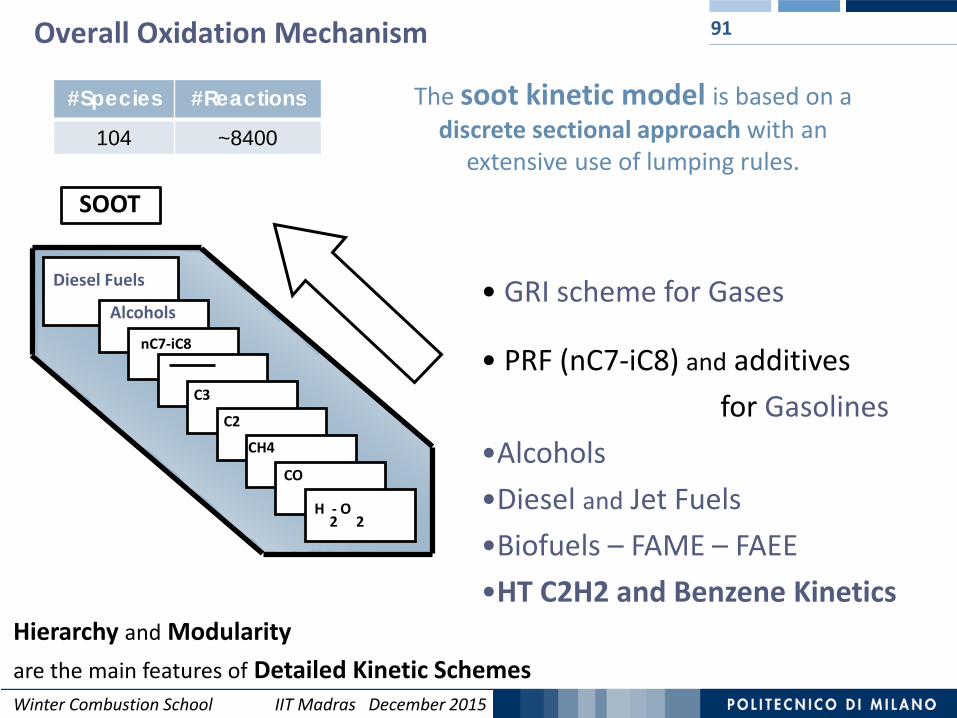
Overall Oxidation Mechanism 91
Hierarchy and Modularityare the main features of Detailed Kinetic Schemes
• GRI scheme for Gases
• PRF (nC7-iC8) and additivesfor Gasolines
•Alcohols•Diesel and Jet Fuels•Biofuels – FAME – FAEE •HT C2H2 and Benzene Kinetics
CO
C3
CH4
C2
nC7-iC8
H - O2 2
Diesel Fuels
Alcohols
The soot kinetic model is based on a discrete sectional approach with an
extensive use of lumping rules.
#Species #Reactions
104 ~8400
SOOT

Winter Combustion School IIT Madras December 2015Winter Combustion School IIT Madras December 2015
92Soot kinetic model: pseudo-species
First soot particle: BIN5 with 320 carbon atoms and equivalent spherical diameter of ~2 nm.
Primary particle: BIN12 with an equivalent spherical diameter of ~10 nm (dp).
Spherical shape (ρsoot = 1.5 g/cm3) up to BIN12 and then aggregates of Np primary particles.
Heavy PAHs (after pyrene) and soot particles are divided in classes of pseudo-species (BINs) and their thermodynamics is estimated using the Benson’s group additivity method.
C. Saggese, S. Ferrario, J. Camacho, A. Cuoci, A. Frassoldati, E. Ranzi, H. Wang, T Faravelli, Combust. Flame (2015)
Molecular mass increase from a class to the next one First heavy PAH: with 20 carbon atoms as
corannulene.
H/C ratio
Homann & Wagner, Proc. Combust. Inst. 1967, 371-379.

Winter Combustion School IIT Madras December 2015Winter Combustion School IIT Madras December 2015
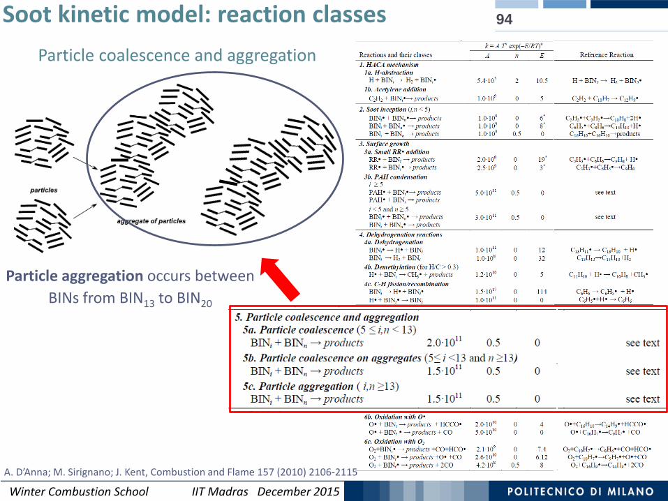
93Soot kinetic model: reaction classes
Particles kinetic can be defined in analogy with the gas phase chemistry following aerosol
dynamic principles.
6 reaction classes are defined:
HACA mechanism Soot inception Surface growth Dehydrogenation Particle coalescence and aggregation Oxidation
C. Saggese, S. Ferrario, J. Camacho, A. Cuoci, A. Frassoldati, E. Ranzi, H. Wang, T Faravelli, Combust. Flame (2015)
Winter Combustion School IIT Madras December 2015Winter Combustion School IIT Madras December 2015
94Soot kinetic model: reaction classesParticle coalescence and aggregation
Particle aggregation occurs between BINs from BIN13 to BIN20
A. D’Anna; M. Sirignano; J. Kent, Combustion and Flame 157 (2010) 2106-2115

Winter Combustion School IIT Madras December 2015Winter Combustion School IIT Madras December 2015
Comparison with experimental data: particle size distribution functions (PSDF)
95
Discrete sectional method is employed to solve the time evolution of the particle size distribution function of the ethylene flame
J. Camacho; C. Liu; C. Gu; H. Lin; Z. Huang; Q. Tang; X. You; C. Saggese; Y. Li; H. Jung; L. Deng; I. Wlokas; H. Wang, Combust. Flame (2015) C. Saggese, S. Ferrario, J. Camacho, A. Cuoci, A. Frassoldati, E. Ranzi, H. Wang, T Faravelli, Combust. Flame (2015)

Winter Combustion School IIT Madras December 2015Winter Combustion School IIT Madras December 2015
96