pressure governor - wfr wholesale fire and · pdf filethe fire research pro-s pressure...
TRANSCRIPT

PRO-S Rev0404
1
PRESSURE GOVERNOR

PRO-S Rev0404
3
INTRODUCTIONOverview
The Fire Research PRO-S pressure governor uses state of the art programmablemicroprocessor technology. It will maintain a steady pump discharge pressure bycontrolling the engine speed or maintain a selected engine RPM. The PRO-S willoperate in one of two modes, pressure or RPM.
In pressure mode the PRO-S maintains a constant pump discharge pressure. Thedischarge pressure is monitored and compared to the selected pressure setting, theengine RPM is varied to keep the discharge pressure at the selected setting.
In RPM mode the PRO-S maintains a constant engine RPM. The pump dischargepressure is monitored, it can vary but will be limited to an increase of 30 PSI. If thedischarge pressure increases 30 PSI, the pressure governor will automatically lowerthe engine RPM to reduce the discharge pressure.
All controls and indicators are located on the front of the control module.
FeaturesPower Up in Pressure Mode
Automatic Regulation of Pump Discharge Pressure
Manual Control of Pressure or Engine RPM Settings
Field Programmable Presets
Diagnostic Capabilities
No Pressure or RPM Variation When Changing Modes
Limits Increase of Pressure When in RPM Mode
Recognition of No Water Condition With Automatic Response
Interlock Signal Recognition
Return to Engine Idle With the Push of a Button
High Idle Kit (Optional)
24 VDC (Optional)
KPa (Optional)

PRO-S Rev0404
4
SpecificationsThe PRO-S is available in various models. Each model is programmed to interface
with specific engines. All models provide the same functions, push button controls,and digital readout for the management of pump discharge pressure. (Refer to Table 1for detailed specifications.)
Table 1. PRO-S Specifications
Note 1: 24 VDC Optional
PRO-S 1 PRO-S 2 PRO-S 3 PRO-S 4 PRO-S 5 PRO-S 6 PRO-S 7 PRO-S 8 PRO-S 10
ENGINE Cummins (IS Series)
Detroit Diesel (Series 50 and
60)
Non-Electronic
Navistar and Detroit Diesel (Series 40)
Caterpillar Ford Mack Scania Mercedes
SUPPLY VOLTAGE (See Note 1)
12 VDC 12 VDC 12 VDC 12 VDC 12 VDC 12 VDC 12 VDC 12 VDC 12 VDC
SUPPLY CURRENT 1.0 AMP 1.0 AMP 3.0 AMP 1.0 AMP 1.0 AMP 1.0 AMP 1.0 AMP 1.0 AMP 1.0 AMP
RESPONSE (Idle to full
governed speed)5 SEC 5 SEC 30 SEC 5 SEC 5 SEC 5 SEC 5 SEC 5 SEC 5 SEC
RECOVERY (After open or close of valve)
1.5 SEC 1.5 SEC 1.5 SEC 1.5 SEC 1.5 SEC 1.5 SEC 1.5 SEC 1.5 SEC 1.5 SEC
RPM CALIBRATION None None Manual None None Manual None Manual None
DATALINK PROTOCOL J1587 J1587 J1587 J1587 J1587 J1587

PRO-S Rev0404
5
Table 2. Pressure Transducer Output Voltage
PRESSURE (PSI)
VOLTAGE (VDC)
0 0.5100 1.917150 2.625200 3.33250 4.04300 4.75
Pressure Transducer
Model Number: PRO31PT2
Pressure Range: 0 - 300 PSI
Proof Pressure: 800 PSI
Excitation Voltage: 5 VDC
Output Voltage: 0.5 - 4.75 VDC
(See Table 2)

PRO-S Rev0404
6
GENERAL DESCRIPTIONThe PRO-S pressure governors are compatible with the following engines:
PRO-S 1 Cummins ISB, ISC, ISM, and ISL
ComponentsThe PRO-S pressure governors consists of the following components:
Control Module
Pressure Transducer
Throttle Servomotor (Non-electronic engines only.)
High Idle Kit (Optional)
Cables
Control Module
The pressure governor control module is waterproof and has dimensions of 4.25inches high by 4.25 inches wide by 3.5 inches deep (4.5 inches deep on non-electronicand 24 VDC units). All controls and indicators are located on the front of the controlmodule. (Refer to Controls and Indicators.)
Pressure Transducer
The pressure transducer is mounted on the pump discharge manifold. It providesan input signal to the control module that is proportional to the discharge pressure.
Throttle Servomotor (Non-Electronic Engines Only)
The throttle servomotor is installed on engines that do not have electronic enginecontrol systems. It provides the mechanical connection between the control moduleand the engine throttle. The travel of the linear actuator arm is 1.85 inches.
High Idle Kit (Optional)
The High Idle Kit provides the components to install this option including a DPDTswitch, 2500 ohm potentiometer, an indicator light, two diodes, and a cable.

PRO-S Rev0404
7
Controls and IndicatorsAll controls and indicators are located on the front of the control module. It contains
the push button electronic controls, LED indicators, and a digital display. (Refer toFigure 1.)
PRESET Button
The green PRESET button sets the pump pressure or engine RPM to apreprogrammed value. This button is also used in the programming of pressure orRPM preset values.
IDLE Button
The red IDLE button immediately sets the engine to idle RPM. This button can beused in an emergency or for a normal shut down after operations.
SETTING Display
The SETTING display will show a diagnostic error code, IdLE for engine idle,the pressure setting or the RPM setting. The LED digital display has daylight brightdigits at least 0.56 inch high.
INCREASE Button
During operations the yellow INCREASE button raises pressure or RPM setting.This button is also used in the programming of the pressure or RPM preset values.
DECREASE Button
During operations the yellow DECREASE button lowers pressure or RPM setting.This button is also used in the programming of the pressure or RPM preset values.
RPM Button
The green RPM button selects the RPM mode of operation.
RPM LED
The red RPM LED is on to indicate operation in the RPM mode.
PRESSURE Button
The green PRESSURE button selects the pressure mode of operation.
PRESSURE LED
The red PRESSURE LED is on to indicate operation in the pressure mode.

PRO-S Rev0404
8Figure 1. Controls and Indicators
PRESSUREButton
DECREASEButton
IDLEButton
PRESETButton
INCREASEButton
SETTINGDisplay
RPMButton
PRESSURELED
RPMLED
PRO-S Rev0404
9
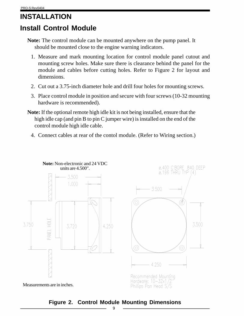
INSTALLATIONInstall Control Module
Note: The control module can be mounted anywhere on the pump panel. Itshould be mounted close to the engine warning indicators.
1. Measure and mark mounting location for control module panel cutout andmounting screw holes. Make sure there is clearance behind the panel for themodule and cables before cutting holes. Refer to Figure 2 for layout anddimensions.
2. Cut out a 3.75-inch diameter hole and drill four holes for mounting screws.
3. Place control module in position and secure with four screws (10-32 mountinghardware is recommended).
Note: If the optional remote high idle kit is not being installed, ensure that thehigh idle cap (and pin B to pin C jumper wire) is installed on the end of thecontrol module high idle cable.
4. Connect cables at rear of the contol module. (Refer to Wiring section.)
Figure 2. Control Module Mounting Dimensions
Note: Non-electronic and 24 VDCunits are 4.500".
Measurements are in inches.

PRO-S Rev0404
10
Install Pressure TransducerThe discharge pressure transducer is mounted on the discharge manifold of the
pump. A T-fitting can be used to share the pressure gauge outlet on the dischargemanifold. If there is a check valve in the discharge side of the pump, mount the transducerbefore the check valve.
Note: Install the pressure transducer upright so water in the end of thepressure transducer is able to drain back into the pipe.
1. Screw the transducer into a 1/4-18 NPT hole.
Caution: Do not use the main body that houses the electronics to tighten thepressure transducer. Damage to the transducer may occur.
2. Tighten the transducer with a 9/16-inch wrench on the lower hex fitting.
3. Connect the pressure transducer cable from the control module to the pressuretransducer. (Refer to Wiring section.)
Figure 3. Pressure Transducer
Caution: Do not use the main bodythat houses the electronics to tighten
the transducer. Damage to thetransducer may occur.
1/4-18 NPT
1.02"
0.86"12345678901234567890123456789012345678901234567890123456789012345678901234567890123456789012345678901234567890
0.80"
Lower HexFitting
SupplyVoltage
SignalOutput
Ground
1.04"
Main Body

PRO-S Rev0404
11Figure 4. Fuel Control Arm
Install Throttle Servomotor (Non-Electronic EngineOnly)
The throttle servomotor (FRC part number PRO-34M.) is used for engines thatdo not have an electronic engine control system.
The throttle servomotor has a universal mounting flange with six mounting holes.It should be mounted in a location where vibration and high temperatures will beminimized.
Note: The throttle cable (or linkage rod) varies for each installation and is notsupplied with the throttle servomotor.
Minimize Engine Oscillation
It is important to note that in order to minimize engine oscillations the stroke at thepoint the cable attaches to the fuel control arm should be 2 inches.
The length of the stroke at the point the cable attaches to the fuel control arm has adirect effect on the sensitivity of the system. The shorter the stroke, the more sensitivethe system. Most engine oscillations occur because this stroke distance is too short.To increase the stroke distance, increase the length of the fuel control arm.
Note: Extending the effectivelength of the fuel control arm willincrease the stroke distance anddecrease the sensitivity of the
system.
ThrottleCable
Typical FuelControl Arm
ShorterStroke
Longer Stroke

PRO-S Rev0404
12
Installation
1. Place the throttle servomotor in position and secure.
Note: The total motion of the linear actuator rod is approximately 1.85inches. The motion of the fuel control arm must be more than 1.85 inchesto prevent damage to the arm. It is recommended that the fuel control armhave a two inch stroke at the point the cable attaches.
2. Connect the throttle cable to the linear actuator rod and the fuel control arm.
3. Test the motion of the fuel control arm by operating the servomotor linearactuator rod to its minimum and maximum positions. Ensure that the fuel controlarm operates freely. (Connect +12 VDC to red wire and ground to black wireto extend actuator rod, reverse wires to retract rod.)
4. Connect the 2-pin connector to the servomotor cable. (Refer to Wiring section.)
Figure 5. Throttle Servo Motor
TypicalFuel
ControlArm
SetScrew
INCREASE
ThrottleCable
1.85"Throw
MAX MIN
ThrottleServoMotor
LinearActuator
Rod
MountingFlange
ThrottleCable2"
StrokeMIN MAX
TypicalThrottle Cableand Support
Bracket
Throttle Servo Motor CableConnector
Pin/Wire DescriptionA/Red +12 VDC to ExtendB/Black +12 VDC to RetractNote: Extend refers to the INCREASEdirection as shown on the servo motor.
2-PinPackard
Connector
Note: The throttle cable is notsupplied with the throttle servomotor.

PRO-S Rev0404
13
Install Optional High IdleThe High Idle Kit (FRC part number PRO-38H) provides the necessary components
needed to install this option including a DPDT switch, 2500 ohm potentiometer, anindicator light, two diodes, and a cable.
The high idle cap may be installed on the end of the control module high idle 3-pinDeutsch connector. This cap is removed to install the high idle cable.
Note: Refer to the high idle calibration procedure after the installation iscomplete to adjust the 2500 ohm potentiometer for high idle engine RPM.
Install the potentiometer in a location that will allow access to adjust it during thecalibration procedure.
For wiring of the high idle components refer to Figure 7. Optional High IdleSchematic.

PRO-S Rev0404
14
OPERATIONOn power up the PRO-S will be in the pressure mode of operation. The SETTING
display will show IdLE. If there is a problem, the SETTING display will show anerror code. Refer to the Diagnostics section for error code descriptions.
The minimum pump discharge pressure must be greater than 15 PSI forthe PRO-S governor to take control of engine speed.
No variation in discharge pressure or RPM will occur when changing betweenpressure and RPM modes.
INCREASE/DECREASE Buttons
The INCREASE and DECREASE buttons are used to change pressure andRPM settings or program preset values. The rate and amount the numbers changewhen a button is pressed depends on the mode and how long the button is held.
In Pressure Mode. Press either button momentarily to change the pressure settingby 1 PSI. Press and hold the button for more than 2 seconds and the pressuresetting will change by 5 PSI twice and then by 10 PSI until the button is released.
In RPM Mode. Press either button momentarily to change the RPM setting by10 RPM. Press and hold the button for more than 2 seconds and the RPMsetting will change by 50 RPM twice and then by 100 RPM until the button isreleased.
Switching Between Operating Modes
• No variation in discharge pressure or RPM will occur when changing betweenpressure and RPM modes.
• When changing to RPM mode, the RPM setting will be the RPM that thepump was operating at in pressure mode.
• When changing to pressure mode the pressure setting will be the pressure thatthe pump was operating at in RPM mode.
When the PRO-S SETTING display shows IdLE:
Press the mode button and the PRO-S switches modes immediately.
When the PRO-S SETTING display shows a value (operating at some setting):
Press and hold the mode button for 3 seconds and the PRO-S changes modes.(This is to avoid an accidental change over if the buttons get bumped.)
High Pump Discharge Pressure at Engine Idle
Once the governor has set the engine to idle, it can do no more to reduce dischargepressures. To reduce discharge pressure the pump operator can gate incoming water,reduce pressure at the intake relief valve, gate discharges, or disable the pump.

PRO-S Rev0404
15
Pressure Mode OperationIn the pressure mode of operation the PRESSURE LED will be on. The PRO-S
will maintain a constant discharge pressure. It will adjust the engine RPM automaticallyto compensate for variations in pressure.
Note: When changing from RPM mode to pressure mode the pressure settingwill be the pressure that the pump was operating at in RPM mode.
1. Press and hold PRESSURE mode button for 3 seconds.
Result: PRESSURE LED goes on.
2. Press PRESET and/or INCREASE/DECREASE button to select theoperating discharge pressure.
3. Press IDLE button to bring engine to idle RPM.
Result: SETTING display shows IdLE.
Switching Supply Water
When switching the water supply source from tank to hydrant, draft to hydrant, ordraft to relay, water flow through the pump can become turbulent and the positivepressure from these sources may generate a sudden pressure surge. It is recommendedthat the PRO-S be set in RPM mode before changing the water supply source.
No or Low Supply Water
There are situations during pump operations when there may be no or low supplywater. This can be due to an empty water tank, a problem on the intake line, or whenswitching the water supply source.
In pressure mode the PRO-S will increase the engine RPM and attempt to maintainthe selected pressure setting. If the discharge pressure drops below 45 PSI but staysabove 15 PSI the PRO-S will go into a prime cycle. It will set the engine to 1100 RPM,if the pressure does not rise above 45 PSI in 7 seconds (30 for PRO-S 3) the PRO-Swill set the engine at idle RPM. The PRO-S will continue repeating the prime cycle aslong as the discharge pressure is between 15 and 45 PSI.
If the discharge pressure drops below 15 PSI the engine RPM will go to idle andthe SETTING display will show the selected setting. When the discharge pressurerises above 15 PSI the PRO-S will resume control at the previous selected setting.
Opening/Closing Discharge Valves
In pressure mode the PRO-S will maintain the pressure setting regardless of thenumber of discharge lines that are opened or closed providing there is a sufficientwater supply. As lines are opened the discharge pressure will start to drop and thePRO-S will raise the engine RPM to maintain the required pressure. As lines are closedthe discharge pressure will start to rise and the PRO-S will lower the engine RPM tomaintain the required pressure.

PRO-S Rev0404
16
RPM Mode OperationIn the RPM mode of operation the RPM LED will be on. The PRO-S will maintain
a constant engine RPM.The pump discharge pressure can vary but, as a safety feature, the PRO-S limits
the increase in pressure to 30 PSI. As the discharge pressure approaches this limit thePRO-S will automatically lower the RPM to prevent a high pressure surge. The RPMLED will blink as the PRO-S sets a lower RPM. This lower RPM will be the newoperating RPM setting.
Note: When changing from pressure mode to RPM mode the RPM settingwill be the RPM that the pump was operating at in pressure mode.
1. Press and hold RPM mode button for 3 seconds.
Result: RPM LED goes on.
2. Press PRESET and/or INCREASE/DECREASE button to select theoperating RPM.
3. Press IDLE button to bring engine to idle RPM.
Result: SETTING display shows IdLE.
Change Preset Setting (Pressure or RPM)The preset button allows the operator to go to a pre-programmed pump pressure
or engine RPM during operations. The setting will be shown on the SETTING display.This procedure is to change the setting in the program.
Note: The engine must be running and the pump engaged interlock circuitmust be closed.
1. Press IDLE button.
Result: SETTING display shows IdLE.
2. Press PRESSURE or RPM mode button to select the setting to be changed.
Result: LED indicator goes on for mode selected.
Note: The RPM display must show IdLE before changing the preset.
3. Press and hold PRESET button. (Continue to hold through step 4.)
Result: SETTING display flashes previous programmed preset.
4. Press INCREASE or DECREASE button to change preset setting.
5. Release PRESET button.
Result: The new preset is programmed. SETTING display shows IdLE.

PRO-S Rev0404
17
System Options
High Idle
Note: If the optional remote high idle kit is not being installed, ensure that thehigh idle cap (supplied) is installed on the end of the control module highidle cable.
The RPM that the engine will run at when the high idle circuit is engaged is set byadjusting the 2500 ohm potentiometer. Refer to Calibration section if the potentiometerhas to be adjusted.
To engage the high idle, place the high idle switch to ON. The high idle indicatorlight will go on and the engine will run at the set RPM. The PRO-S SETTING displaywill show the high idle RPM.
With the high idle switch set to on, the PRO-S controls will operate normally forRPMs above the high idle RPM. The DECREASE and IDLE buttons will not lowerthe engine RPM below the high idle setting.
It is recommended that the high idle switch be set to OFF when operatingthe pump.
CAUTION: The high idle switch must be off before shutting the engine off.Failure to do so could result in damage to equipment.

PRO-S Rev0404
18
High Idle Option CalibrationThe RPM that the engine will run at when the high idle circuit is engaged is set by
adjusting the 2500 ohm potentiometer.
1. Loosen the lock nut on the potentiometer.
2. Place the high idle switch to ON.
3. With a small screw driver adjust the wiper arm on the potentiometer to set theengine RPM. (Use a reference tachometer monitor engine speed.)
4. Tighten the lock nut on the potentiometer. Ensure the engine RPM does notchange when the lock nut is tightened.
5. Place the high idle switch to OFF.

PRO-S Rev0404
19
DIAGNOSTICSThe information listed in Table 3 is to aid in troubleshooting a problem. The
diagnostic code will be shown in the SETTING display on the control module.
Table 3. Diagnostic Codes
Code Problem Probable Cause>No voltage at the interlock input>Datalink cable not connected / connected to wrong port>Broken wire / bad connector contact on datalink cable
E2 Bad data on datalink >Noise interference (radio frequency or electrical)>Datalink cable not connected / connected to wrong port>Engine not running / ignition key on
[Non-Electronic engines] RPM signal not detected
>Broken wire / bad connector contact on alternator cable
>No voltage at the interlock input>Internal datalink problem - bad control module>Datalink shorted>Transducer cable not connected>Broken wire / bad connector contact on transducer cable>Defective pressure transducer
E6 N/A N/A
>Low supply water, intake line problem, valve closed, pump not primed, etc.
>Defective pressure transducer
E3
Cannot transmit over datalink (No response from ECM)
E4
E1 No communication on datalink
[Electronic engines] RPM data not detected on datalink
E5 Discharge pressure transducer not detected
E7Not able to raise pump pressure from idle to set pressure

PRO-S Rev0404
20
WIRINGThe following figures include the schematics, wiring diagrams, block diagrams,
and cables for the PRO-S series governors.
Note: If optional 24 VDC unit is installed references to +12 VDC will be +24VDC.
Power
Figure 6. PRO-S Power Supply Wiring
Note: The interlock circuit will ensure that specific safety conditions are met beforethe pump becomes operational. The interlock circuit may include relays, switches,and/or indicator lights for the following conditions:- Parking Brake On- PTO Engaged- Transmission In Drive/Netural- High Idle- OK To Pump- Throttle Ready
From Control ModulePower Supply 3-PinDeutsch Connector
Power SupplyCable
White
GND
Black
Red
Ignition Key
+12 VDC
From InterlockCircuit +12 VDC
Power Supply CableConnector
Pin/Wire DescriptionA/Red +12 VDC*B/Black GroundC/White Interlock Circuit
* +24 VDC with option.
Note: Refer to Figure 19 forinformation on installing aflyback diode.

PRO-S Rev0404
21Figure 7. Optional High Idle Schematic
High IdleFrom Control Module
High Idle 3-PinDeutsch Connector
Black
Red
High Idle2500 Ohm
Potentiometer
High IdleIndicator
Light
High Idle ON/OFFSwitch
White
From ParkingBrake
Diodes(IN4002 orequivalent)
NC
C
FromTransmission
Neutral 12VDC
FromPump Engaged
12VDC
To Control Module WhiteInterlock Wire
(Located in power cable.)
Pump EngagedIndicator Light
GND
NC
NO
NC
NO
NO
C
C
GND
GND
GND
High IdleCable
High Idle CableConnector
Pin/Wire DescriptionA/Red +12 VDCB/Black GroundC/White Signal
Note: If the optional remote high idle kit isbeing installed, the high idle cap must beremoved. (It is installed on the end of thecontrol module high idle cable and has ajumper wire between pins B and C. )
ON
OFF
FRC kit part numberPRO-38H.

PRO-S Rev0404
22Figure 8. Pressure Transducer Wiring
Pressure Transducer(Top View)
SupplyVoltage
SignalOutput
Ground
From Control ModulePressure Sensor 4-Pin
Deutsch Connector
PressureTransducer
Cable
PressureTransducer
Pressure TransducerCable 3-Pin Sensor
ConnectorPin/Wire DescriptionA/Black GroundB/Red Supply VoltageC/White Signal Output
Pressure TransducerCable 4-Pin Deutsch
ConnectorPin/Wire Description1/Red Supply Voltage2/BlackGround3/White Signal Output4/Yellow Cable Shield
Pressure Transducer

PRO-S Rev0404
23
Commonly foundunder the driverside dashboard.
Figure 9. Common OEM Connectors
Common OME Connectors
Typical 6-pin Deutsch diagnostic connector.
Pin A J1587 Datalink PositivePin B J1587 Datalink Negative
Typical 9-pin Deutsch diagnostic connector.
Pin F J1587 Datalink PositivePin G J1587 Datalink Negative
FRONTVIEW
BF
E
A
C
D
GH
J
ED
AB
C
F
FRONTVIEW

PRO-S Rev0404
24
PRO-S 1 WIRINGCables
Figure 10. Cummins PRO-S 1 Wiring(Sheet 1 of 3)
PowerSupply
EngineControl
High Idle Cap(Refer to Figure 7)
PressureTransducer
(Refer to Figure 8)
-Pow
er S
uppl
y
-Eng
ine
Con
trol
-Hig
h Id
le
-Pre
ssur
e Se
nsor
-Thr
ottle
-RPM
Sig
./ J1
587
GOVERNOR
HighIdle
PressureSensor
AC
B
B
Power Supply(Refer to Figure 6)
Engine Control(See Sheet 2) E
Connector KeyA 4-Pin DeutschB 3-Pin DeutschC 3-Pin PackardD 2-Pin PackardE 3-Pin Sensor
Engine Control CableConnector
Pin/Wire DescriptionA/Black Signal ReturnB/White Signal to ECMC/Red 5 VDC Reference
RPM Sig./ J1587
J1587 Datalink(See Sheet 2)
D
J1587 DatalinkCable Connector
Pin/Wire DescriptionA/Red Datalink +B/Black Datalink –

PRO-S Rev0404
25
Figure 10. Cummins PRO-S 1 Wiring(Sheet 2 of 3)
Cummins Harness Connections
Interface Information
The ECM Remote Acceleration Option has to be set to ON. The diagnostic toolcannot be used to do this, an Insight service tool must be used. Refer to an authorizeddealer to program this option.
ISB, ISC, and ISL Engine Interface
ECM 50-PinB Connector
J1587 (–)J1587
Datalink (SeeSheet 1)
Black WireRed Wire J1587 (+) 50
49
20109
456
REMOTE THROTTLE RETURN (SRTN B)EngineControl
(See Sheet 1) REMOTE THROTTLE PEDAL POSITION INPUTREMOTE THROTTLE +5VDC (VSENSOR B)Red Wire
Black Wire
White Wire
SELECTED THROTTLE CONTROL SWITCHREMOTE THROTTLE ON/OFF INPUT
Note: Supply aground when thepump interlock
circuit is engaged.
Note: Supply a ground from the pumpinterlock circuit. This assumes thatthe ECM is set with Automotivegovernor as the default mode.
ECM 50-PinJ2 Connector
J1587 Datalink (–)J1587
Datalink (SeeSheet 1)
Black WireRed Wire J1587 Datalink (+) 20
10
322126
0314
ECM Return (Sensor)EngineControl
(See Sheet 1) Remote Accelerator PositionSensor SupplyRed Wire
Black Wire
White Wire
Max Operating Speed/Governor Type SwitchRemote Accelerator On/Off Switch
Note: Supply aground when thepump interlock
circuit is engaged.
Note: Supply a ground from the pumpinterlock circuit. This assumes that theECM is set with Automotive governor
as the default mode.
ISB02/ISC03/ISL03CM850 Model Engines

PRO-S Rev0404
26
ISM Engine Interface
Figure 10. Cummins PRO-S 1 Wiring(Sheet 3 of 3)
ECM 50-PinC1 Connector
J1587 DATALINK (–)J1587 DATALINK (+)
J1587Datalink (See
Sheet 1)Black WireRed Wire
2726
494821
4325
ACCELERATOR SUPPLY RETURNEngineControl
(See Sheet 1) REMOTE ACCELERATOR POSITION ACCELERATOR SUPPLY (+)
Black WireRed WireWhite Wire
ACCELERATOR GOVERNOR SWITCHREMOTE ACCELERATOR SWITCH
Note: Supply a ground from the pumpinterlock circuit. This assumes thatthe ECM is set with Automotivegovernor as the default mode.
Note: Supply aground when thepump interlock
circuit is engaged.
ECM 50-PinJ2 Connector
J1587 Datalink (–)J1587
Datalink (SeeSheet 1)
Black WireRed Wire J1587 Datalink (+) 20
10
322126
0314
ECM Return (Sensor)EngineControl
(See Sheet 1) Remote Accelerator PositionSensor SupplyRed Wire
Black Wire
White Wire
Max Operating Speed/Governor Type SwitchRemote Accelerator On/Off Switch
Note: Supply aground when thepump interlock
circuit is engaged.
Note: Supply a ground from the pumpinterlock circuit. This assumes that theECM is set with Automotive governor
as the default mode.
ISM02-CM870Model Engines