pressure tube and pressure vessel reactors; certain comparisons
TRANSCRIPT

AE-49
w<
Pressure Tube and
Pressure Vessel Reactors;
certain comparisons
P. H, Margen, P. E. Ahlstrom
andB. Pershagen
AKTIEBOLAGET ATOMENERGI
STOCKHOLM • SWEDEN • 1961

AE-49
PRESSURE VESSgj-^^ANlVPjySSSU^
COMPARISONS
By P. II. Margen, P. K. Ahlström, B. Pershagen
Summary
In a comparison between pressure tube and pressure vessel type
reactors for pressurized D^O coolant and najoral uranium, one
can say that reactors of these two types having the same net electri-
cal output, overall thermal efficiency, reflected core volume and
fuel lattice have roughly the same capital cost. In these circum-
stances, the fuel burn-up obtainable has a significant influence on
the relative economics. Comparisons of burn-up values made on
this basis are presented in this report and the influence on the re-
suits of certain design assumptions are discussed. One of the com-
parisons included is based on the dimensions and ratings .proposed
for CANDU. Moderator temperature coefficients are compared and
differences in kinetic behaviour which generally result in different
design philosophies for the two types are mentioned, A comparison
of different methods of obtaining flux flattening is presented.
The influence of slight enrichment and other coolants, (boiling D^O
and gases} on the comparison between pressure tube and pressure
vessel designs is discussed and illustrated with comparative designs
for 400 M"W electrical output.
This paper was presented at the EAES Enlarged Symposium on
Heterogeneous Heavy Water Power Reactors, Mallorca October,
10 - 14th, I960.
Printed April 1961

LIST OF CONTENTS
Page
1. Introduction i
2. Designs chosen for comparison 4
3. First idealised comparison of burn-up 5for similar core and reflector dimensions
4. Practical burn-up values 7
5. Design margins 8
6. Lattice limitations 8
7. Output limitation 9
8. Power costs 10
9» Slight enrichment 11
10. Boiling D2O 13
11. Internal superheating 14
42. Other coolants 15
13, Concluding remarks 16
Acknowledgement 17
References 18
Appendix I
Appendix II
Appendix III
Table 1
Table 2
Table 3
FIGURES
Fig, l and 2Fig. iFig. 4Fig. 5Fig. 6Fig. 7Fig. 8Fig. 9Fig. 10Fig. 11Fig. 12

Pressure vessel and pressure tube designs; certain comparisons
byP.H. Margen, P.E. Ahlström, B. Pershagen
1. Introduction
The primary goal for work in Sweden on nuclear reactors has been the
attainment of economic power production with a system which could
operate on natural uranium, so as to give a certain degree of indepen-
dence of fuel supplies and a favourable trade balance. This and some
subsidiary aims of the Swedish programme such as an interest in nu-
clear district heating have led to a concentration on D?O as moderator.
Most work has been done on the pressure vessel type of design for this
moderator as adapted for instance in the Ågesta reactor (previously
called R3/Adam), '* ' the current designs for Marviken ' (previously
called R4/Eve) and certain preliminary designs for larger stations of
the pressurized D^O type. Boiling D2O with pressure vessel design is
regarded as a logical future development for this reactor type.
The basic aims of economic power production with a system which could
operate with natural uranium could also be fulfilled with D?O moderated
reactors of other types than those described above, in particular designs
with pressure tubes using pressurized D2O or various other coolants.
Evaluation of various factors for and against pressure vessels as com-
pared to pressure tubes have tended to change during the past five or six
years partly as a result of new information on the subjects of reactor
physics and materials, partly as a result of the development of certain
design philosophies in different organisations. It is still not possible to
prove which system is the best from the aspect of behaviour of materials,
prevention of leakage, facility of repairs of fuel changing machines and
other engineering components, but it is possible to make certain gene-
ralized comparisons from the aspect of reactor physics and kinetic be-
haviour, and to draw certain conclusions concerning the influence of
these factors on economics. The present paper attempts to make such
comparisons with a view to testing the logic of proceeding with the
Swedish development line as compared with alternative types.
* AB Atomenergi, Stockholm
** State Power Board, Stockholm

4.
2. Designs chosen for comparison
The largest part of this paper concerns comparisons of pressurized
D7.O reactors of the pressure tube and pressure vessel types. For
the pressure tube type it is convenient to select the basic CANDu de-4)
sign ' illustrated in fig. 1 as a basis for discussion. This design has
horizontal pressure tubes of Zircaloy insulated by a gas gap from the
Zircaloy calandria tubes, a cold moderator, the heat of which is dis-
carded; and bi-axial on-load fuel changing. The irradiation exposure
in the central channels can be increased compared to the peripheral
channels to obtain the desired degree of flux flattening, Because of
the bi-axial system of fuel element changing, there is no axial reflec-
tor; whilst the; current design envisages a relatively thick radial re-
flector.
For the pressure vessel type a variety of different designs have-been
proposed and the one chosen for this discussion has the virtue that it
has a relatively large number of features m common with the pressure
tube design thus facilitating the comparison. The design is illustrated
in fig. ?- and can be regarded as a development of the concepts for /Vgesta
and Marviken. The pressure vessel has a domed lid filled with a steam
cushion used for pressurizing the reactor, the top layer of water being
insulated from the coolant by normally stagnant layers of water. The
lid has only one central fuelling port, through which a manipulator
loads and removes fuel whilst the reactor is on load. Each channel con-
tains two fuel eletnents which can be axially reversed to obtain reaso-
nably uniform axial irradiation exposure, and the elements can be tran-
sported radially xxsing the manipulator, without leaving the tank. The
shroud tubes stay in the pressure vessel during fuel element changing
operations, but can be exchanged if damaged by removing the lid. The
D..O circulates first downwards through the moderator space and then
upwards through the fuel channels,, and the resulting overpressure on
the shroud tubes is assumed to be met by slightly corrugating the tubes.
The design would normally allow for a uniform axial and radial reflector
thickness.
Since the moderator and coolant channels are connected in series, the
design can utilize a negative moderator temperature coefficient to some
extent for self regulation with load changes, pump failures and power

surges, though stronger self regulating properties can be obtained in
other pressure vessel c
before this conference.
other pressure vessel designsf e. g, that described in another paper5)
It should be noted that essential components of the above pressure ves-
sel design such as the fuel manipulator are at the drawing board stage
whereas similar components for the pressure tube design are already
under manufacture for the prototype reactor NPD-2, From this point
of view the pressure tube design has an advantage which will be disre-
garded in the subsequent discussion.
3. First idealised comparison of burn-up for similar core and re-
flector dimensions.
As a firstf somewhat academic, comparison we may assume that the
pressure vessel design is dimensioned in such a way that it has exactly
the same fuel element cluster (19 x 14, 5 mm rods), and the same spa-
cing between rods and between elements as the pressure tube design
(CANDU). The moderator temperature for the pressure vessel design
can be chosen to give the same overall thermal efficiency as for the
pressure tube design (which results in a moderator temperature of
about 225 C) and the ideal burn-up ' of the two systems may then be
compared. As discussed in more detail later, pressure vessel and pres-
sure tube designs having the same core and reflector dimensions, net
electrical output and overall thermal efficiency may be expected to have
roughly similar capital costs, so that a comparison of the ideal burn-up
obtained is significant for the overall economy. The moderator tempera-
ture of about 225 C required by this comparison does not result in exces-
sive pressure vessel dimensions, as shown for instance by column 2a in
table 1 though the dimensions could be made more suitable for pressure
vessel technology by using a greater height/diameter ratio for the core.
The calculations presented in table 1 columns 1 and 2a and described in
greater detail in Appendices 1 and 2 indicate that the pressure vessel
design in these circumstances has a higher ideal burn-up than the pres-
sure tube design, the difference being about 1100 MWd/ton. This is illu-
strated also by the reactivity burn-up curves fig. 3. It should be men-
tioned, however, that Swedish designers consider that the value of 0c 6
chosen in CANDU for the crossectional channel area ratio of coolant to
*) The expression "ideal burn-up11 signifies in this paper the burn-upcalculated for a hypothetical continuous fuel element changing systemwhere all degrees of irradiation exist at every point of the lattice. Fluxflattening is disregarded, It is expressed in MW days per metric ton ofU in this paper.

6.
fuel, A /A,, is very low, particularly for pressure vessel designs,
where it is desired to select a higher value for the following reasons;
a) to avoid obtaining a large positive void coefficient according to the
calculations presented in fig. 4 and to obtain a stronger negative mo-
derator temperature coefficient of reactivity, according to the cal-
culations presented in fig. 5. A strong positive void coefficient is
considered a disadvantage from the aspect of safety and a negative
moderator temperature coefficient is an advantage from the aspect
of self regulation in pressure vessel designs where the coolant and
moderator are closely coupled,
b) to reduce the power rating of the back-up supplies to the pumps ne-
cessary to guard against supply failures (since an increase in the
coolant to fuel area ratio greatly reduced the pumping power r e -
quirement), and to improve cooling with natural circulation in ver-
tical coolant channel designs.
c) to reduce the risk of damage due to bowing of rods when using rela-
tively long rods.
In addition, this reduces of course pumping power requirements.
To satisfy these requirements according to current data, values of A /A,
of about 2, 0 are visualised for a reactor having the channel ratings selec-
ted for CANDU. The influence of this on burn-up is illustrated by curves
1 and 2 in fig. 6 which show that the advantage in burn-up of the pressure
vessel design increases with increasing values of A /A, (since this increases
the amount of structural material in the pressure and calandria tubes), re-
aching the value 3700 MWd/ton for an area ratio of 2, 0.
The above discussion indicates that the advantages of the pressure tube
reactors regarding a lower moderator temperature is not sufficient to
compensate for the disadvantage of more structural material and extra
gas gaps in the core, resulting in a net disadvantage regarding ideal burn-
up of 1100 to 3700 MWd/ton, according to the value chosen for A /K? in
the range 0, 6 to 2, 0.
It must, however, be emphasized that current methods of physics calcu-

7.
lations still contain a considerable degree of uncertainty especially for
high values of burn-up9 so that the results cited, above must be treated
with caution. The numerical values depend also to some extent on design
assumptions such as the permissable stress for the pressure tubes (based
in this case on Canadian values) and the minimum practicable thickness
of shroud tubes.
4. Practical burn-up values
a) without flux flattening
If the bi-axial system of continuous on-load fuel element changing used
for the CANDU design is employed without radial flux flattening, it gives
the same radial flux distribxition as for our postulated ideal system, and
a slightly more peaked axial flux distribution. This results in a slightly
(2 to 3%) higher burn-up than for the ideal system. The same is true for
the fuel element changing system assumed for the pressure vessel de-
sign, where the elements are axially inverted after half the burn-up is
reached, provided this takes place continuously i. e. one element at a
time. This is illustrated by fig. 7 curves 2 and 4.
For both types of systems, the flux will vary slightly in adjacent channels
due to differences in irradiation, and this will slightly reduce the burn-up.
The above discussion suggests that, in the absence of radial flux flatte-
ning, both systems give a burn-up which is about equal to the ideal burn-up.
b) with radial flux flattening
With the bi-axial system of fuel loading, it is currently envisaged to
achieve flux flattening by allowing the fuel elements in the central channels
to achieve a higher exposure than in the periphery. For the pressure vessel
system on the other hand it is proposed to achieve flux flattening largely by
transposing elements from the peripheral zone towards the central region
after a given burn-up has been reached which can be done rather conveni-
ently in that design without removing the fuel elements from the reactor
vessel. As illustrated in fig. 8 (see also Appendix 1) the latter system
reduces by a factor of about two the reduction in burn-up caused due to
flattening the flux by a given factor. From this point of view the proposed
pressure vessel design has an advantage compared to the proposed pres-
8.
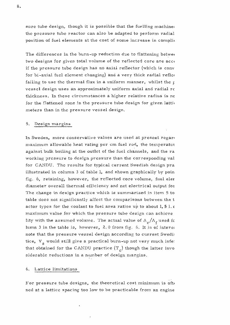
sure tube design, though it is possible that the fuelling machine:
the pressure tube reactor can also be adapted to perform radial
position of fuel elements at the cost of some increase in compli<
The differences in the burn-up reduction due to flattening betwe<
two designs for given total volume of the reflected core are acci
if the pressure tube design has no axial reflector (which is conv
for bi-axial fuel element changing) and a very thick radial refle<
failing to use the thermal flux in a uniform manner, whilst the j
vessel design uses an approximately uniform axial and radial re
thickness. In these circumstances a higher relative radius is ne
for the flattened zone in the pressure tube design for given lattii
meters than in the pressure vessel design.
5. Design margins
In Sweden, more conservative values are used at present regar<
maximum allowable heat rating per cm fuel rod, the temperatui
against bulk bailing at the outlet of the fuel channels, and the ra
working pressure to design pressure than the corresponding val
for CANDU. The results for typical current Swedish design pra
illustrated in column 3 of table 1, and shown graphically by poin
fig. 6, retaining, however, the reflected core volume, fuel eler
diameter overall thermal efficiency and net electrical output foi
The change in design practice which is summarized in item 5 to
table does not significantly affect the comparisons between the t
actor types for the coolant to fuel area ratios up to about 1, 5 i. €
maximum value for which the pressure tube design can achieve
lity with the assumed volume. The actual value of A /A. used fc
lumn 3 in the table is, however, 2. 0 from fig. 6. It is of intere;
note that the pressure vessel design according to current Swedi;
tice, V would still give a practical burn-up not very much infe:
that obtained for the CANDU practice (T ) though the latter invo
siderable reductions in a number of design margins.
6. Lattice limitations
For pressure tube designs, the theoretical cost minimum is oft»
ned at a lattice spacing too low to be practicable from an engine

9.
aspect, and this tends to increase costs slightly, especially for reactors
with very large heat ratings, where one obviously desires to reach high
heat rates per unit core volume.
For pressure vessel designs of the type described, this particular de-
sign limitation does not exist, as a more close lattice pitch is possible
from the engineering aspect, but there is, instead, a desire to adopt
low volume ratios of moderator to fuel (i. e. low lattice pitches) and
high values of A /A, as mentioned earlier in order to obtain negative
reactivity coefficients. Even in this case some departure from the
theoretical point for minimum cost is thus desirable.
In both cases, the cost increase compared to the theoretical optimum
is small, i. e. a few percent.
7. Output limitation
In a pressure tube design an increase in output can obviously be ob-
tained by increasing the number of pressure tubes without obtaining
fundamentally new problems in design or manufacture, though in prac-
tice it would generally be desirable to let an increase in output be ac-
companied by some increase in the channel rating. For pressure ves-
sel designs it is not possible to increase the volume of the vessel in
proportion to the reactor output indefinitely, and this has resulted in
a fear that pressure vessel designs for natural uranium have a definite
limit in the possible output.
Some design studies having a bearing on this subject have recently been
made in Sweden. Table 2, design 6, gives data for a preliminary design
for 400 MW electricity. Fig. 9» curve 1, shows the calculated optimum
diameter plotted against net electrical output and indicates that an in-
crease in output by a factor 2 corresponds to an increase in the optimum
diameter by only about 17%, Curve 2 shows furthermore that a reduction
in diameter by about 10% (and a reduction in the reactor volume by near-
ly 30%) increase the overall cost per kWh by only about 3% compared to
the minimum cost. The curves indicate that diameters of 6 to 6. 5 m
corresponding to wall thicknesses of 85 to 95 mm with low alloy steel
are of interest for reactors with an output of 400 to 500 MW electricity
per reactor. Swedish manufacturers believe that vessels having such
dimensions can be manufactured with the equipment envisaged towards

10.
the end of the nineteensixties. VOT most Swedish sites it should be
possible to transport the vessels by water in one piece, but even
partial fabrication on site may be considered practicable at a later
date when additional experience is available. There seems according-
ly no reason to fear that presstxre vessels will limit the output of
pressurized D?Q reactors by the time large units require to be built.
The fact that the cost of pressure vessel designs might be increased
by a few percent d\ie to a departure from the apparent optimum volume
for the largest outputs does not make pressure vessel designs less
favourable than pressure tube designs at large outputs since pressure
tube designs for very large outpiits require to increase the value of
A /A, if optimum heat ratings are used, which also results in slightly,
increased costs.
8. Power costs
As mentioned earlier, it is believed that pressure vessel and pressure
tube designs having the same total volume of core plus reflector, the
same net electrical output and the same overall thermal efficiency have
approximately the same capital coot. Actually the turbo generator will
probably be a little cheaper for the pressure tube design because of
the somewhat higher steam conditions / and the building may also be
cheaper because of the reduced mass of D->O at high temperature,
which reduced the possible pressure build-up in accidents. On the
other hand the cost of the pressure tubes (19 tons of Zircaloy) for
CANDU and the calandria is estimated to be somewhat higher than the
cost of a pressure vessel, and the fuelling machines for bi-axial
fuelling are more complicated and therefore probably more expensive
than the machine for changing fuel in the pressure vessel design.
Also the IX, O investment for a given volume is greater in the pressure
tube design than the pressure vessel design because of the lower
moderator temperature. These factors probably cancel roughly so
that one cannot expect to find significant differences in the capital
CO Sto
The influence of higher steam conditions on the thermal efficiencyis offset by the heat discarded by the moderator cooling circuit.

1 1 ,
The differences in burn-up mentioned in para* 4 correspond to a cost
difference of 0, 15 to 0. 5 milis/kWh according to the basic cost data
used in this paper. On the other hand, there are considerable un-
certainties in the determination of the burn-up, and the above state-
ment concerning capital costs is of course very approximate. The
calculated difference in fuel costs cannot, therefore, be taken as a
proof of economic superiority of the pressure vessel design for natural
uranium, though it does give a hopeful indication concerning possible
future economy»
9 o Slight enrichment
A slight degree of enrichment can be used to increase the burn-up
by very considerable amounts for D?O moderated reactors as well
as to reduce the reactor volume, at the price of an increase in the
cost of fuel per kgg To preserve negative void and moderator
temperature coefficients at the high burn-up values, resonance
absorption should however be increased, which brings about a reduction
in the desired moderator to fuel volume ratio and an increase in the
desired coolant to fuel area ratio. From what has been said previously
in paragraphs 3 and 6, it will appear that pressure vessel designs can
more easily be adapted to these conditions than pressure tube designs.
An analysis of the economics of slight enrichment requires knowledge
of the influence of enrichment of the cost per kg of delivered fuel.
For the cost of nuclear material price lists are published by the A. iC.C.
and generally used for such calculations. For the cost of fabrication
and conversion on the other hand, no generally established figures
exist. Fig. 10 cxirve 1 shows the cost data used for this item in this
paper for natural uranium elements, whilst the shaded band of figures,
curve Zs shows corresponding costs used for slightly enriched elements.
The difference in level between these curves is caused largely by the
omission of the UF, conversion process for natural uranium elements,
as well as reduction of interest charges and uranium losses during
fabrication, and lastly a slight cost reduction due to a reduction in
precautions necessary during fabrication. On the same figure are
shown on the one hand the Canadian estimate for the cost for natural
uranium fuel elements and a cost figure cited by the U.S.A. in
connection with the EURATOM agreement for enriched element. It will

1 2 .
be seen that these figures differ by very large amounts from the costs
assumed in this paper, the Canadian costs being much lower ' and the
U.S.A. costs much higher. It would be of great value if the specialists
in the various countries could jointly clarify the reasons for these
discrepancies. Table 2 shows technical data and approximate cost
estimates for a number of' 400 MW reactor designs based on the technical
status considered practicable for 1970. Design 6 represents pressurized
D?O design for natural uranium, whilst design 7 shows a pressurized
D?O reactor of pressure vessel design for 1 % enriched uranium. The
enrichment was used to increase the burn-up from 8550 to a rrean
value of 14 200 MWd/ton and to reduce the reflected volume by J6 %,
and which is estimated to achieve a net reduction in costs by about 5 %.
This design has not however been optimized so that a slightly larger
reduction is probably obtainable. The fuel cycle costs are shown in
greater detail in table 3 which also indicates that graded enrichment
employing a certain proportion of natural uranium elements iis more
advantageous than uniform enrichment, since it avoids submitting all
the fuel through extra processes such as the UF, conversion process.
It should be mentioned that the calculations for graded enrichment
were based on the simplifying assumption that the rate of plutonium
production is independent of the distribution of enrichment.
It might be argued that the selection of slight enrichment is a funda-
mental departure from the policy of independency of fuel supplies and
a favourable trade balance. On the other hand it is possible to design
the slightly enriched system in such a way that the fuel elemeiits can
be replaced in an emergency by natural uranium elements with a
higher moderator to fuel volume ratio and somewhat lower rod diameter,
giving the same electrical output, though at a much lower burn-up and
somewhat higher fuel cost per kWh. The cost for this emergency
operation would indeed be slightly higher than for a system optimized
from the start for natural uranium,, but would be quite satisfactory
*) One reason for the lower Canadian cost may be an assumptionthat the raw material prices for uranium will drop, since theCanadian cost figure in fig. 10 was calculated as a differencebetween the total cost of fuel element in ref. 4 and the currentU.S.A. price for natural uranium.

1 3 .
as an emergency measure. As regards the trade balance, this would
still be more favourable with 1 % enriched uranium than with say 2 %
to 3 % enriched uranium necessary for H?O moderated reactors.
Table 3, design 10, shows typical fuel cycle costs for a large H^O
moderated reactor. It appears that the slightly enriched D^O moderated
reactor can achieve a saving in fuel costs of about 1.3 milis/kWh,
and would incur extra capital charges and leakage costs of about
1.1 milis/kWh for Swedish accountancy practice according to the
discussion in Appendix III. The latter figure is obtained by considering
only the differences in the installation of pressurized reactors of the
pressure vessel type for D?O and H?O and should be reasonably
accurate since these two types of station have so many components
in common, These figures suggest that slightly enriched pressurized
water reactors for D-,0 can economically compete with reactors for
HpO when the comparison is based on large units and Swedish
accountancy practice. The comparison, however, assumes that both
types have reached the same stage of technological development,
whereas at the present time H?O reactors have an advantage in this
respect.
10. Boiling D O&_ 2 _
Direct cycle boiling reactors have the advantage of higher efficiency
for given design pressure than pressurized water reactors as well
as the advantage of omitting the main heat exchangers. They have
the disadvantages of
a) more acute leakage problems, especially in the condenser
b) limitations in the core imposed by voids.
Whilst D-,0 moderator accentuates problem a) compared with H?O
moderator, it makes b) less severe, since it is possible with D?O
to keep the void coefficient very slightly negative by choosing suitable
coolant to fuel area ratios, thus avoiding the very strongly negative
void coefficients present with HUO, which limit the power rating for
large H^O boiling reactors. This advantage of I>2O exists however
primarily with pressure vessel designs, since pressure tube designs
can hardly afford the large coolant to fuel area ratios which would
be necessary. Fig. 11 shows the design assumed for the boiling
D^O reactor data in this paper. It is based on natural circulation.

14.
The advantages of the pressure vessel design from this point of view
are accentuated if the reactor is designed for natural circulation,
as this requires still larger coolant to fuel area ratios, as illustrated
by Fig. 12, where it is assumed thatthe largest permissible volume
fraction of voids from the aspect of burn-out and for hydrodynamic
instability (with the assumed degree of throttling at the channel inlet)
is 81 %. The method of calculation used for this figure is described
in ref. 6.
Table 2, design 8, shows a design for a direct cycle boiling water
reactor indicating that one might expect a saving of 0 - 16 % of the
cost per kWh compared to the cost for pressurized D^O, depending
primarily on the amount by which the costs of leakage are estimated
to exceed those for pressurized D?O, and the somewhat uncertain
estimates concerning the costs of extra measures required to
minimize leakage for the direct cycle.
-̂*° Internal superheating
Internal superheating appears to offer only marginal economic with
D̂ O moderated systems as long as stainless steel has to be used as
the canning material but would offer significant improvements in
economy if zirconium alloys suitable for superheated steam were
developed.
Internal superheating can be used without appreciable com plication
to the core in pressure tube designs of the pressurized D?O or boiling
D^O types though there would be certain additional problems in control.
With pressure vessel designs of the pressurized water type, internal
superheating would introduce complications which make its merits
very doubtful, whereas with pressure vessel designs of the boiling
water type, internal superheating could be used without introducing
such a high degree of complication, as illustrated for instance by
the designs presented in ref. 7. The problem is rather similar to that
for H?O moderated boiling reactors, where designs incorporating
internal superheating are also being seriously considered. An alterna-
tive method which avoids the use of headers for the superheated steam
inside the pressure vessel is illustrated by the broken lines in fig. 11.
It is assumed in this case that the superheater elements are uniformly
distributed over the entire core except a narrow region near the
reflector, thereby producing a large pitch of the holes in the bottom
of the pressure vessel.

1 5 ,
Summarizing one can say that internal siiperheating will probably at
some future date be used with advantage in both pressure tube and
pressure vessel reactor types, though in the latter case it will be
used only in conjunction with the boiling type of reactor.
12„ Other coolants
The pressure tube design lends itself for obvious reasons better than
the pressure vessel design to the use of other coolants than D?O.
The only one amongst these other coolants which has been studied
in reasonable detail in Sweden is CO? gas, which offers the attain-
ment of very high efficiencies on the assumption that satisfactory
beryllium cans are developed at a reasonable price, and satisfactory
solutions to the internal insulation of pressure tubes are developed.
The results from one of the approximate design studies made for this
reactor type in Sweden ' are summarized as design 9 in table 2»
Just as the other designs in this table, it has been optimized for
400 MW electricity, and in common with the designs 6 and 8 it uses
natural uranium as fuel,, It appears however that the advantage of a
superior thermal efficiency compared to pressurized D?O and boiling
DTO are offset by the influence of the lower optimum heat rating of
the fuel as dictated by considerations of heat transfer from the can
to the gas, the relatively large and expensive gas circulators5 and
the greater cost of beryllium cans as compared to Zircaloy cans.
Assuming for instance that beryllium canned fuel elements cost 30 %
more than Zircaloy canned elements having the same rod diameter
(13. 5 mm), the overall economy of the CO-, cooled reactor appears
to be intermediate between that of pressurized D?O and boiling D?O
designs - the limits of error of the estimates however exceeding
the calculated differences in costs.
In Canada somewhat similar economic comparisons have been carried
out between reactors cooled by pressurized D9O on the one hand and9}
H^O steam ' on the other hand leading to the conclusion that pressurized
DoO appeared to offer the better economy, even if zirconium alloy
cans suitable for 480 C steam were developed. The advantage of
steam from the aspect of coolant inventory costs and thermal efficiency
appear to be more than offset by the reduction in burn-up caused by

16.
the large area ratio, A /A,., resulting from the relatively small
coolant temperature range which can be used with high pressure
steam, whilst the advantages of organic liquids from the aspect of
pressure containment and fuel inventory are counteracted by the
parasitic neutron absorption and inferior heat transfer.
Whilst future developments might change the picture, the preliminary
comparisons made suggest that there has not appeared as yet a design
for other coolants than D?O which would give pressure tube reactors
a significant advantage over pressure vessel designs.
13» Concluding remarks
The discussion in this paper appears to lead to the following main
conclusions.
1. Pressure vessel designs offer somewhat higher burn-up values
than pressure tube designs when both types are designed for the
same volume of core plus reflector, the same fuel geometry and
the same net electrical output and overall thermal efficiency,
and accordingly, very roughly, the same capital* cost. This may
give the pressure vessel type a slight overall cost advantage,
though the differences are not significant in relation to possible
errors in burn-up and cost predictions. The above applies when
both types of designs use similar design philosophies regarding
margins against a variety of occurances.
2. Pressure vessel designs have better possibilities of utilizing the
moderator to achieve some degree of self-regulation and of
dimensioning the coolant channels to given negative void
coefficients and good self-regulation. The assessment of the
importance of this factor varies however between different design
organisations»
3. With the equipment which manufacturers consider it reasonable
to order within a few years in Sweden, it is visualized that
pressure vessels can be made for the largest electrical outputs
per reactor which are considered to be of interest, e.g. well
over 400 MW electricity per reactor with natural uranium.

1 7 .
40 Slight enrichment appears to give somewhat lower costs than
natural uranium for D.-,O moderated reactors even for very large
electrical outputs, particularly with pressure vessel designs
which have greater freedom to use low moderator to fuel moderator
ratios and higher coolant to fuel area ratios than pressure tube
designs. Slight enrichment also increases the economic power
output from a pressure vessel of given dimensions. With slight
enrichment, the D?O moderated and cooled designs for large
electrical outputs appear also to be able to compete economically
with the more heavily enriched H?O moderated reactors.
50 Direct cycle boiling reactors for D?O appear to offer certain
possibilities of making important cost reductions compared with
pressurized D-,0 reactors,, Pressure vessel designs are more
suitable for boiling reactors than pressure tube designs because
of the possibility of using larger coolant to fuel area ratios which
is an advantage from the aspect of void coefficients and natural
circulation,
6O Both types of design lend themselves to the use of internal super-
heating although this can be performed with less complication to
the core in pressure tube designs,
7; Pressure tube designs ledn themselves better than pressure
vessel designs to the use of other coolants than D-,0, but compar-
able design studies for large reactors have not as yet indicated
significant potential gains due to the use of other coolants such as
CO? gas, H?O steam, or organic liquids,,
No doubt many other points comparing pressure tube and pressure
vessel designs can be found, but their evaluation is currently a matter
of opinion. The points indicated here have at least served to strengthen
the belief in Sweden in the future of the pressure vessel type of reactor
using pressurized D?O and ultimately boiling D-,0 as coolant.
Ackno wledgern ent
The authors wish to thank Dr Lewis of the AECL for his permission
to use data for the 1959 study of CANDU. Time limitations made it
impossible to incorporate the latest I960 data.

18 .
REFERENCES
1. P.H. Margen, H. Carruthers5 B. Hargö, G. Lindberg and
B. Pershagen:
R3. - A Natural Uranium Fuel Heavy Water Moderated Reactor
for Combined Electricity Production and District Heating. Proc.
Geneva Conf. P/l35 (1958)
2. E.G. Malmlöw, O. Mileikowsky, S. Ryman and I. Wivstad:
Nuclear Heat and Power for the City of Stockholm. The Joint
Swedish. Project. World Power Conference, Madrid. (I960)
3. E.G. Malmlöw: Heavy Water Cooled Reactors With Pressure
Vessels. EAES Mallorca Conference (I960)
4. W.B. Lewis: Pressure-Tube Heavy-Water-Cooled Reactors.
EAES Mallorca Conference (I960)
5. B. Hargö, A. Dahlgren, G. Andersson: Utilizing the Larger Mode-
rator Volume over Heavy Water Power Reactor. EAES Mallorca
Conference (I960)
6. H. Lange, O. Steinman: Calculation of Two Phase Pressure Drop
in Tubes and Fuel Element Bundles (in Swedish) AB Atomenergi IPV-19
19. 5. 60
7. M. Treshow, D. Shaftman, L. Temp lin, M. Petrick, B. Höglund
and L. Link: A Study of Heavy Water Central Station Boiling Reactors
(CSBR) ANL-5881, Sept. 1958
8. P.H. Margen: Preliminary Cost Comparison Between Four D_O Mode-
rated Reactors for 400 MW Electricity. AB Atomenergi IP-1 7. 6. I960.
9. Partial Economic Study of Steam Cooled Heavy Water Moderated
Reactors. AECL-1018 (I960)
10. B. Pershagen, G. Andersson and I. Carlvik: Calculation of Lattice
Parameters for Uranium Rod Clusters in Heavy Water and Correla-
tion with Experiments. Proc. Geneva Conf. P/151 (1958)
11. G. Andersson: Formulae for Calculation of Physical Properties of
Heav " Water Moderated Reactors with Cylindrical Lattice Cells and
Uniform Burn-up. AB Atomenergi RFR-47. 20.11.1959.

19.
12. Heavy Water Lattices. IAEA Symposium, Vienna (I960)
13. P.E. Ahlströrn: Burn-up Calculations for a Thermal Reactor.
AB Atomenergi RFR-10 (in Swedish) 15. 9. 1958
14. P. Weissglas: Theoretical Calculation of the Effect on Lattice
Parameters of Emptying the Coolant Channels in a D?O Mode-
rated and Cooled Natural Uranium Reactor. AB Atomenergi
RFR-67 12.5.60
15. P.E. Ahlström: Reactivity Changes by Emptying the Coolant
Channels for Different Coolant Areas and Lattice Pitches in the
R4/Eve Reactor. AB Atomenergi RFR-66/R4-101 (In Swedish)
30. 5. 60
16. P.E. Ahlström, P. Weissglas: Spatial Variations of the Isotopic
Concentrations in a Fuel Rod. AB Atomenergi RFR-79 (6. 9. I960)


APPENDIX I
B urn-up and flux flattening in a two-zone reactor
1. Introduction
Consider a reactor of given dimensions, fuel elements and lattice
spacing. Let the burn-up without flux flattening for a continuous charge
and discharge system, where all points in the reactor contain fuel of
all degrees of burn-up, be u (= "ideal burn-up"). If the radial flux is
flattened in a central zone, the average burn-up will be reduced by a
certain amout depending on the method of obtaining the flattening.
Three different methods are considered, namely
a) All fuel elements are discharged when they have reached the same
burn-up, u . Flux
in the central zone.
burn-up, u . Flux flattening is achieved by inserting absorbers
b) Fuel elements in the peripheral zone are discharged at a given
burn-up, u? , which is lower than the average, u , for the reactor,
•whilst the fuel elements in the central zone are discharged at a
given burn-up, u,, higher than the average. Both zones are fed
with new fuel elements.
c) Fuel elements in the peripheral zone are removed at a given burn-
up, u? , and transferred to the central zone, where they are allowed
• to reach the burn-up u . The peripheral zone is fed with new fuel
elements. The central zone is fed partly with fuel elements trans-
ferred from the peripheral zone and partly with new fuel elements
which are also taken to the burn-up u .c


It 2
2. One-group theory for a two-zone reactor
For the purpose of comparing the methods of obtaining flux
flattening one-group theory is considered adequate.
Introduce the following notation:
R1 = radius of central (flattened) zone
R? = radius of core
R = extrapolated radius
H = extrapolated height
B, = buckling of central zone
2B ? = buckling of peripheral zone
jB = radial buckling of peripheral zone
j = 2.4048 = first zero of Jo(x)
F r Q = radial form factor ( = ratio of maximum to average radial flux)
without flux flattening
F = radial form factor with flux flattening
The following relations are easily derived:
Jo</3Rx) Y1 (/3RX) - Y o (j3Rx) J][ (01^) = O
which is a criticality equation determining
Fro
x


I t3
1
Fr
We also
B
have
2
2
~rr~
R r -,- ^ Jj (/3RJ) Yx (j3R? ) - Yj tfR^ ^ (/3R2)x 2 L • J
2 ~ \ ~ji—x
\
3. Comparison of different methods of obtaining flattening
IVe assume continuous charging, discharging and transposition of
fuel elements and use the following definitions:
2u, = ideal burn-up corresponding to B,
u = - " - B 2
2 2
u = burn-up for method a)
u, = - " - b)
u = - " - c)
c '
R1 2 Sum of (fuel element positions x flux) for the central/ i \ ~-, zonen = ( i r--) I = — — — — _ —___
2 Sum of (fuel element positions x flux) for the entirereactor
In case (a) the attainable burn-up is given by
u = u,a 1
In case (b) fuel elements are removed at different burn-up, u, and
u^ in the central and peripheral zones respectively. The average burn-up
froin the aspect o£ fuel cost is
n , 1-nu_. -,- _„


In case (c) it can be shown that the attainable burn-up, u ,2 c
corresponds to a buckling, B , given by
The fraction, z, o£ fuel element positions in the central zone occupied
by elements which have been transferred from the peripheral zone is
u - uo ,_ c 2 1 - nuo2 n
The condition that 0 S z < 1 implies that
which is always fulfilled in practical cases.
4. Numerical results
Numerical calculations have been made for a 200 eMW pressure
vessel reactor, case 2a (cf. Table 1). The results expressed as the
reduction in burn-up as a function of the degree of flux flattening for
the three methods of obtaining the flattening are shown in fig. 8. It is
seen that method (c) gives a considerable advantage over other methods,
method (a) being, of course, least advantageous.
The relative reduction in burn-up are found to be approximately in-
dependent of the degree of flattening. If u is the ideal burn-up without
flattening the following ratios are obtained
( u - ua) : ( u - u^) : ( u - uc) = 1 : 0, 44 : 0, 23
The reason why method (c) gives so much better results than method
(b) is largely the very large difference between the burn-up values at
which elements are removed from the reactor with method (b) in the
flattened and unflattened zones, whereas all elements are removed at
the same burn-up with method (c).


APPENDIX II
Reactor physics calculations
1. Lattice parameters
The lattice parameters were calculated by the methods described by
Pershagen et al (ref. 10). The full set of formulae were given at the IAEA
symposium on Heavy Water Lattices in Vienna (1959) (ref, 12).
The method used for calculation of reactivity changes with irradiation
is described in ref, 13.
2. Void coefficients
The calculations of the void coefficients were made by the methods
developed by Weissglas (ref. 14). The calculations were made for a fuel
element with 27 rods and 13, 5 mm rod diameter in a hexagonal (open)
lattice. The details are given in ref. 15 and a future RFR-report. The
uncertainty in the absolute values of the void effect must be considered
very large. However, the curves are supposed to give a correct picture
of the changes in the effect, when changing the coolant area or the lattice
pitch.
The largest changes in reactivity when emptying the coolant channels
come from the changes in U 238 resonance absorption. At small lattice
pitches and large coolant areas the influence of the changes in the non-
leakage probability is dominant. This effect is elsewhere of the same
magnitude as the change of the fast fission factor, but of opposite sign.
The thermal utilization is not very sensitive to the void effect, at least
not with fresh fuel in the reactor. The effect of changes in the neutron
spectrum have not been taken into account. As was shown by Weissglas
they are small with fresh fuel in the reactor. The influence of burn-up,
absolute temperature etc. has not been investigated.
It should be observed that the calculations give the change in
reactivity at total and momentaneous loss of coolant in all channels


II : Z
of the reactor. The changes of the temperaturesf the geometrical
dimensions etc. are not included in the calculations.
3. Moderator temperature coefficient of reactivity
The moderator temperature coefficient of reactivity has been cal-
culated by a new programme for the Ferranti Mercury computer. The
programme determines the lattice parameters at different temperatures
as a function of the average irradiation of the fuel. 'When calculating the
changes of isotopic concentrations with burn-up the non-uniform distribu-
tion of flux over a fuel element is included (ref. 16). The lattice parameters
are calculated by almost the same formulae as given in ref. 11, A com-
plete description of the programme will by given in an RITR-report, which
is now being prepared.
The temperature coefficients are calculated as —r—fi, whereo J- mm
eff „ is the reactivity and T is the average moderatorm•t
eff
temperature. The non-leakage probability has been determined by one-
group-theory. The coefficients are "point-coefficients", which means
that the macroscopic distribution of the fuel isotopes are not included.
To find the effective coefficiert one has to calculate a weighted average
value over the reactor considering that the irradiation is different in
different parts of the core.

APPENDIX III
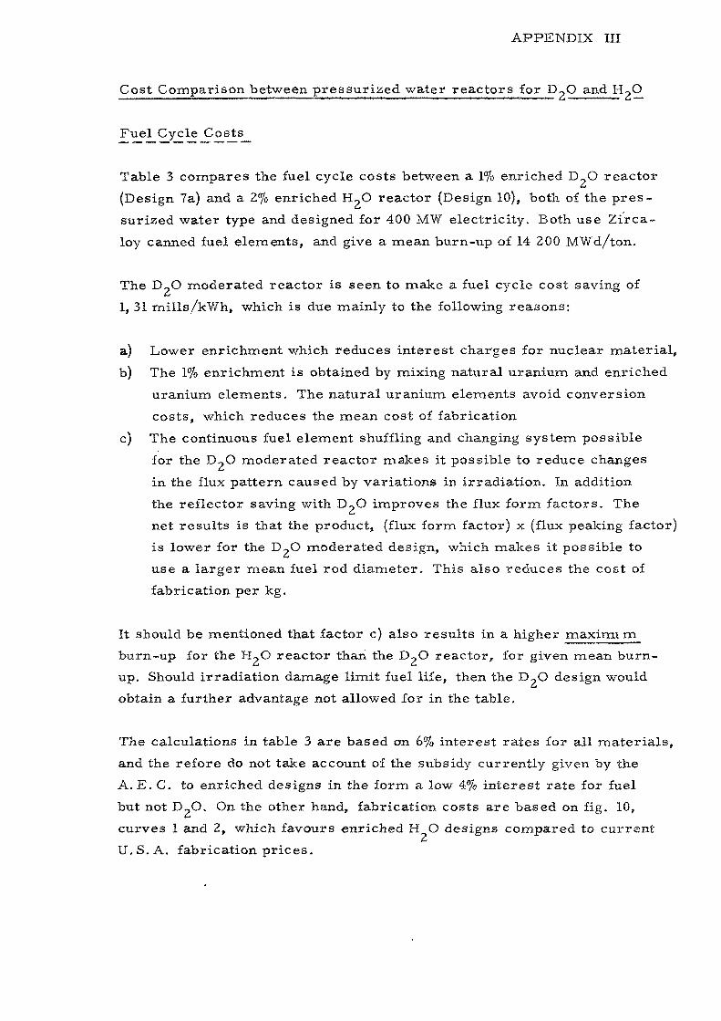
Cost Comparison between pressurized water reactors for D?O and HgO
Table 3 compares the fuel cycle costs between a 1% enriched D_O reactor
(Design 7a) and a 2% enriched H~O reactor (Design 10), both of the pres-
surized water type and designed for 400 MW electricity. Both use Zirca-
loy canned fuel elements, and give a mean burn-up of 14 200 MWd/ton.
The D?O moderated reactor is seen to make a fuel cycle cost saving of
1, 31 milis/kWh, which is due mainly to the following reasons;
a) Lower enrichment which reduces interest charges for nuclear material,
b) The 1% enrichment is obtained by mixing natural uranium and enriched
uranium elements. The natural uranium elements avoid conversion
costs, which reduces the mean cost of fabrication
c) The continuous fuel element shuffling and changing system possible
for the D2O moderated reactor makes it possible to reduce changes
in the flux pattern caused by variations in irradiation. In addition
the reflector saving with D~O improves the flux form factors. The
net results is that the product, (flux form factor) x (flux peaking factor)
is lower for the D~O moderated design, which makes it possible to
use a larger mean fuel rod diameter. This also reduces the cost of
fabrication per kg.
It should be mentioned that factor c) also results in a higher maxirru m
burn-up for the H-.O reactor than the D?O reactor, for given mean burn-
up. Should irradiation damage limit fuel life, then the D?O design would
obtain a further advantage not allowed for in the table.
The calculations in table 3 are based on 6% interest rates for all materials,
and the refore do not take account of the subsidy currently given by the
A. E. C. to enriched designs in the form a low 4% interest rate for fuel
but not D_O. On the other hand, fabrication costs are based on fig. 10,
curves 1 and 2, which favours enriched H O designs compared to current
U. S. A. fabrication prices.


III: 2
Capital charges maintenance and leakage costs
The H~O reactor achieves cost savings regarding the following points:
a) The D~,O inventory and leakage costs are avoided,.
b) the size of the pressure vessel is reduceds which also affects tmilding
dimensions,
c) the standard of design and construction from the aspect of leakage
prevention can be relaxed slightly, •which reduces costs.
The significance of points a) and b) can be reduced by increasing the
reactor rating as this makes possible a low D,,O investment and low
tank volume per MW electricity. For design 7 in table 2, for instance
point a) amounts to 46 $/kW or 0, 76 mills/kWh and a charge of 10%
per year for inventory and leakage. Point b) is estimated to amount roughly
to 15 $/kTV or Of 25 millc/kWh, since the dimensions of the pressure vessel
have a relatively email influence on total costs for large reactors with a
high specific heat rating. Point c) is difficult to estimate, but has been
assumed to be 7 J$/kW or 0, 12 mills/kWh. The combined effect of the
three points is thus 68 |/kW or 1,13 milis/kWh. This is slightly less
than the extra costs on the fuel cycle discussed earlier, (1, 31 milis/kWh).
It appears from this discussion that large D?O moderated reactors can
compete economically with large H9O moderated reactors for Swedish
accountancy practice, assuming that both types reach the same state of
technological development.


Burn-up Comparisons between Pressure Vessel and treasure tuoe Reactors for 200 MW eicctru-^1 output
I.
1.
2.
3 .
4 .
5 .
6.
7.
8.
11.
A.
9.10.
11 .
12.
13.
14.
15.
16.
17 .
18.
19.
20.
2 1 .
B ,
22.
? 3 .
24.
25 .
26.
27 .
28.
i1).
3 0 .
3 1 .
3 2 .
3 3 .
3 4 .
C
35 .
36.
37.
38.
39 .
40.
4 1 .
D.
42.
43 .
Given data, common to tube & vessel reactors
Net electrical output
Totttl .l^rti väte (fuel + moderator)
Reflected core volume
Fuel element (number & dia. of rods)
Maximum permigsable heat Loading of rode,allov,m£ foa axial, radial & internal formfactors k rod end effect
Katic*i design pressure/working pressure
Mean temperature margin »gainot bulkboiling at channel exit
Other data
Moderator tempo-rature
Design pressure
Working pressure
Corresponding saturation temperature
Coolant outlet temperature
Coolant temperature range
Cool&nt inlet temperature
Temperature of saturated secondary etc am
Steam cycle efficiency (practical)• i
Heat rejected by moderator circuit
li to 1C
Net electrical output
Overall dimenfcions & h«at loadings
Length or height of core* ' (17%)
Diameter of core
Volume o£ core
Volume ratio: corerfuel
Volume of fuel
Axial reflector thicknet-s
Radial reflector thickness
Extrapolated core volume
Form factors;
a) axial
b) radial (partly flattened)
c) internal (approx.)
d) end Decking (approx,)
e) overall
K«quira radius of flattened aono/extrapolatedradiua, R , / R (one group theory)
Total fuel heat rate
Mean heat loading per cm
Ma.... heat loading per cm = 33 x %0
Fuel channel <* pressure veaael data
Maximum flow velocity {nominal}
Inside diameter of shroud or pressure tube
Design stress of pressure tubes
a) cana-fuel
b) presoure tube or shroud tube.fuel
c) CÄlandria tube: fuel
d) total Zrrfuel + + +
e) gas gap:fuel
low alloy äteel
Jnaide diameter of pressure vessel
Wall thickness of pressure vessel
Results of physics calculation»
Burn-up: for idealised, continuous fuel loadingsystem, neglecting flux flattening
Adjusted burn-up
MW
MW
m 3
W/cm
°C
°Cbar
"
"
"
%
%
%
MW
m
m
m 3
-
m 3
m
m
m 3
MW
W/cm
m/sec
m m
bars
bar
mmm
kWd/fcg
kWd/kg
1°Canadian
TUBE
49
102
92
305
293
44
249
251**
32,8
g
B
27,8
200
S.3
82,6
10,4
0. 13
0,39
0,13
0,65
0,63
_
•
9950
9780
Idesign
VESSEL{ea-tne reflecto
CANDU)
5,00
4,58
82,5
17,1
4,82
0
0,70
149
1,466
1,394
1,10
1,05
2,36
0,201
676
23S
562
19 x
V
562
0, 6
0.9
12
225
69
62
278
266
44
222
221
30,2
S
27,8
200
8,2
82,6
0,13
0, 10
••
0,23
-2690
6,28
9!
11110
10950
2b
basis
Vt.SSELr (uniform re-
2 0 0
720
141
14, 5 mmf |
225
74
66
282
i 7 0
4 8
2 2 2
2 2 1
30,2
8
'•7,8
200
4,96
4,96
96
17,1
6,62
0, 340,34
145
1,364
1,720
1, 10
1,05
2,75
0,127
676
204
5.',2
8,6
82, 6
0,13
0,10
-0.23
-
2690
5,94
11100
11025
3
Swedish designbasis
VESSEI
450
2,0
0,85
17
230
65
55
270
253
25
J28
222
30,3
7
-
28,2
203
4,96
4,96
9616, 1
5,97
0, 340,34
145
1,41
1,43
1, 10
1,05
2,35
0,JU
6T6
191
450
3,8
111
0,13
0,13
-0,26
-
2690
5,94
so
8800
8350
a aeparaSe inlet header can be used fcr these channels.
Effective length of UO? column in core is taken to be 97 % of core length
Neglecting the »light axial flux peakinE resulting from the bi-ax.,1 or axial inversion fuelling system, compared to
the ideal distributionOn, group theory. Somewhat tower v.iues obtained bv two sr., ,» theory /or «hr t values cited in item 4)
values cited in item 4).


TABIE 2 DATA FOR FOURD ; O MODERATED REACTORS WITH 400 MW NET ELECTRICAL OUTPUT
1.
1.11.21.11.41.51.6
2 .
2 .1
2 . 2
2 . 3
2 . 4
2 . 5
2 . 6
2 . 7
2 . 8
2 .9
2.102.11
3 .
3 .1
3 . 2
3 .3
3 . 4
3 .5
4.
4.14 . 2
4 . 3
4 . 4
4 . 5
4 . 6
4 . 7
4 . 8
4 .9
4.104.114.124.134.14
4.154. 16
TYPECOOLANTENRICHMENT (mean)
LEADING DIMENSIONSCore height k diameterAxial and radial reflector thickness:.eflccted and unreflected core volumesFuel in coreInside diameter of pressure vesselA all thickness of vessel
LATTICE DIMENSIONS & BURN-UPNumber U diameter of UO2 fuel rodsCanning thickness fc materialCoolant to fuel area ratioInside diameter of coolant channelsModerator (excluding coolant) to fuel volume ratioDesign stress of pressure tubesInside diameter of pressure tubesSectional area of UO2 per channelArea ratios between structural material and UO.,a) fuel cansb) shroud tubes or pressure tubesc) internal insulation (equivalent Zircaloy)Initial conversion ratioEurn-up:a) ideal, without flux flatteningb) practical, with flux flattening
FLUX & HEAT RATING
r.eucttn hwut rateTuel heat rateForm factorsa) axialb) radial (flattened)c) internal (approx.)d) ends "e) overall = a) x b) x c) x d)Max. heat rating per cm of rodMax. can surface heat flux
TEMPERATURES, PRESSURES, VELOCITIES,
Mean temperature of moderatorCoolant inlet temp, (reactor)Coolant outlet temp.Saturation temperature of coolantCoolant working pressureDesign pressureMax. allowable can temperatureCoolant velocity, central channelHeat transfer coefficient
Hot spot factor (can/gas)Hot channel factorSteam content at outlet of central channelSteam pressureSteam temperatureSteam t ,c le efficiencyCirculator power consumption
mmm3
tons Ummm
mmmm
mm
barsmmcm2
MWd/ton
MW
MW
W/cmW/cm2
°C°C°C°Cbari t
°cm/secW/cmZoC
vol % 'bar°C%
6 y
P r e s s u r e v e s s e lpressurized 0^0
natural
6,29x5,390,40 x0,36210/144
796,4193,0
27 X 12,70,5 Zr2,5126,213,6
-
-
34,2
0,1760,129-
0,901
92208550
14201333
1,4141,3291,121,052,21450
105
230
228
258
275
59,570
-
1 %
5,3? s ',610,35 xU,3?
nVvO61,S5,55»1,0
2 7 x 1 1 , 80, 5 Zr
2 ,5
117,6
•MS
--2y, b
o, iy»C.13V-
0,82V
1520014200
n:c1333
1,4051,270
1.111,05^,08450
112
230
228
258
275
59,570
-
> heat t rans fer not
-
220
30,33
-
220
30,33
telling BZO
natural
S, tf a 3,70, 36 » 0,3201/138
69,66,78
100,0
3 9 x 1 3 , 50,5 Zr2.7 .115,513,0
-
-
27,2
0,1660,148
-
0,905
85008270
12301155
1,3821,3571,091,052,15450
99
220
276
276
60,471
-
c r i t i c a l
81
276 f34,4 '
iPressure tube
6ft»»StUfSi
4,64 K 6,600,43x0,32232/1S8
76,5
19 x 13,50,8 Be1,1!90,315,2923
96,227,2
0,2650,5780,1050,840
97509200
12111162
1,3861,2791,091,042,01378
83
100
243
483
.
7585,5600410..565*
1,25-dual pres.8 u r f **cycle»*»39,6***10


4.174.18
4.194.20
4.21
4.22
5.
S.I
5 . 2
5 . 3
5 . 4
5 . 5
5 . 6
5 . 7
5.85.95.10
6.
6 . 1
6 . 2
6.36.4
7.
7 . 1
7.Z
7 . 3
7 . 4
7 . 5
7 . 6
7 .7
7 . 8
7 .9
TYPE
COOLANT
ENRICHMENT (mean)
Other auxiliaries
Heat loss to moderator
Overall thermal efficiency
Net electrical output
Generator rating
External heat transfer surface of heat exchangers
CAPITAL COSTS
A. NUCLEAR PART
D2Oat67,5 $/kg:
a) within tank
b) external system
Engineering plant
%
%
%
MW
MW
m*
$/kW11
a) reactor vessel equipment inside vessel, fuel handling "
b) main heat exchangers circulators and main piping
c) auxiliary circuits
d) instrumentation, control equipment, electricalstation supplies
e) miscellaneous
Building, shielding, ventilation etc.
Eesign &. development
Total, nuclear part
B. CONVENTIONAL PART
Turbo-generator, turbine house, generator switchgearetc.
Total for station (5.5 + 5.6)
Interest during construction
Commissioning cost
Grand Total
FUEL CONSUMPTION COST (see table 3)
Cost of fuel
Net credit for spent fu< 1
Net cost of fuelé
Fuel consumption cost T
SUMMARY OF COSTS
A. FIXED COSTS
D,O leakage costs:
a) percent per year of D2O investment
b) $/kW k year
Capital charges and maintenance
a) plant buildings and overheads (10%/year)
b) D2O (7 %/year)
Fuel inventory costs (table 2)
Total fixed costs * 7. lb + 7.2 + 7. 3
Fixed costs per kWh for 6000 full load hours/year
B. RUNNING COSTS
Fuel consumption cost (item 6.4)
Operation (except maintenance)
Total running cost
Total cost for 6000 h/year = (7.5 + (7.8)
If
II
1 1
II
If
ir
i t
i t
i t
tt
<i
it
i t
milln/kWh
%
$/kW & y«»ri i
i i
n
mill»/kWh
i t
I I
6
P r
pressurized
natural
5.
28,2
400
423
20000
37
19
56
1835
13
915
33
17
196
65
261
31
8
300
88.9
16.8
72.1
1.20(1.49)
3
1.68
24.40
3.92
0.73
30.73
5.12
1.20
0.35
1.55
6.67
7
D?O\1 X
j
.
28,2400
428
20000
23
1942
13
35
12
U
•>1
17
173
6538
29
8
275
159.236,0
123.2
8
boiling D,Onatural
5.
32,5400
420
-
35
11
46
18
8
15
815
32
17
159
74233
28
8
269
84.815.2
69.61.28 fl.19 I 1.08
(1.66)[(1.56)J (1.32)
3
1.26
23.302.94
1.1028.604.76
1.28 [l.l9]0.35
1.63 [1.54]6.39 [6.30]
52.30
22.303.22
0.6528.374.73
1.080.351.43
6.16
9Pressure tube
CO;,natural
5
g
33, 0+
400
470
36000
40
4
44
19
38
15
13
15
34
17
195
62257
31
8
296
105.5
17.288.3
1.21(1.45)
1
0.44
25.203.08
0.8829.604.94
1.210.351.566.50
*)**)
***)
Allows for 10 % increase in heat transfer coefficient and 20 % increase in friction factor due to surface roughening of cans
Logarithmic mean temperature difference in heat exchangers = 46° Cj effective mean temperature of heat intake bysteam = 578° K
Without recovery of heat from moderator for feed heating
With recovery of heat from moderator for feed heating
Assuming that this is second generation station
Not included in the costs cited in ref. 8
Costs in square brackets refer to design with graded enrichment (see table 3). Costs1 in round brackets do not take accountof credit for apent fuel.


TABLE 3 FUEL CYCLE COSTS (6 % interest rate throughout)
A.
1.
2.
3 .
4 .
5.
6.
7.
B .
8.
9 .
10.
11.
12.
13.
14.
15.
16.
17 .
C.
18.
19 .
20 .
2 1 .
2 2 .
General dataDegree of enrichment
Fuel rod diameter (UO2)Burn-up (mean)Pu in depleted fuelU 235 in depleted fuelThermal efficiencyMean fuel heat rating
Fuel consumption costC ost of nuclear materialConversion tIF,/uO2 inc. losses
%
m m
MWd/t
gAg U"%
MW/t
$/kgUIt
Fabrication {function of diam.) "Transport 8i interest costs up totime of loading into reactorTotal cost new fuel (8 to 11)Financial value after irradiation
a) Pub) U 235c) totalCost of separation & clean-up in-cluding interest, and transport.1 % Pu loss & 1 % U 235 lossNet fuel credit = 1 3 - 1 4Net fuel cost = 1 2 - 1 5Fuel consumption cost per kWh
Fuel inventory costs*
Interest on fuel in reactorInterest on 10 % standby fuel
TotalTotal per kWh for 6000 full loadhours/yearTotal fuel cost {6000 h/year) ==. (17) +(21)
It
11
11
II
IT
II
II
mills/kW
$/kW yes»
11
6D 2O
Natural uraniumde»
pressu-rizedD,O
2
0,7
12,788504,17
no
28,217,8
40,5-
44,8
3 , 6
88,9
50,0-
50,0
33,216,872,1
1 1,20(1.49)
r 0,630,100,73
miUs/kWh 0,12
IT 1,32
boilingD O
0,7
13,58270
4.03recoverec
32,516,6
40,5
-
40,8
3 , 5
84,8
48,4-
48,4
33,215,269,61,08
0.32)
0,560,090,65
0,1!
1,18
COcoolea
0 ,7
13,59200
4,20
33,014,9
40,5
-
61,2
3 , 8
105,5
50,4
-
50,5
33,217.288,3
1,21(1,45)
0,760,120,88
0,15
1,36
7 |moderated reactorsigni S l ight ly enrich*
(pressurizeduniformlyenriched
1 ,0
11.8142005,86
not
28,221,7
75,820,654,7
8 ,1
159,2
70,3
-
70,3
34,336,0123,2
1,28(1.66)
0,96
0,141,10
0,18
1,46
d̂ designD2O)
2 grades of enrichmentN.U.elements(45% byweight)
0 ,7
14,19900
5,86**recovered
28,214,4
40,5-
38,7
3,582,7
70,3
-
70,3
34,336,046,7
' 0,70v (1,24)
.0,89 1Q **0,
i,<
0,
1,
enrichedelement(55% byweight)
1,2510,617700
5,86
28,226.4
110,521,063,3
10,5205,3
70,3
-
70,3
34,336,0
1,42 s
(1,72) .66)
0.96 .[3
>6
L8
S6
Pressurised
reactor
2 , 0
10,6142006 , 0
1,0328,220,0
220,022,963,3
18,2324,4
72,079,9151,9
41,4110,5
213,9
2,23(3,38)
2,30
0,352,65
0,44
2,67
(1,61) (1,42) (1,59) (1,84) (1.74) (3, 82)
* *
based on linear depreciation in fuel value from value fer new fuel, item 12 to value after irradiation, item 15 (neglectingreduced burn-up or increased enrichment for first and last fuel charges)Neglecting variations in neutron flux between enriched and natural uranium elements (assuming uniform distribution ofenriched and natural uranium elements)
*** Addition of $ 6/kg for enriched elements+ Figures in brackets, items 17 and 22, show costs without taking into account fuel credit.


Schematic presentation of pressure tube
am! pressure v^-osel designs
Fig. 1
Assumed pressure tube
design
coolant249° C
fuel
fuel
o.moderator 49 <~
coolant» 293 C
r
r
Fuel elementchangingmachines
i
¥
moderator cooling circuit(heat discarcarded)
Fig. 2
Assumed pressure vessel
design
WE WW WW WWW Z 66°C
— 222 C


T T; Material buckling versus idea! burn-up for « Fig, 3
; pressure tube and pressure
10 00MWd/ton U


Void coefficients af a funcUon of <. ooi.-i.nt to
fuel area ratio and moderator to fuel ?rca
ratio
L_Ei&_±
Ap
coolant areaiuel area
moderator are<fuel arc;
ge due to completecoolant channel!»
A p - reactivity ciemptying of th
1


Moderator temperature coefficient ('g £ • )as a function of burn-up (E) for ^ m /different coolant to fuel(of) and moderatorto fuel (£2) area ratios and different designs.
Fig. 5
9 T pcm/10 m
Uniform irradiation of all fuel in thereactor is assume4
0 -10
10
30
Curve Design
tube
a


r—<
(0
>
pre
ssu
re(i
deal)
\ /\ /
//
//
/
//
//
//
/
Comparison of burn-up values for pressure
tube and pressure vessel reactors
(CANDU dimens ons)
1/f
Ii
i
/
//
/
/
/
H
/ *
,̂ p
ress
ure
(ideal)
\ /\ /
//
/
/
/
/
/
ire
tub
e
<n ww Ö<y 'in
d to
•Ji M
01 <
II
u
<
o o o o o oo o o o o oo o o o o o«~i O O CO f- sO
Burn-up. MWd/ton U
/
ire
vess
el
lish
desi
gn
W 4)
On 4*
Ö "•"*
u h
"SS?•rj a) *g^
<i 2 «»h S gII
>
©
Fig. 6
^ r " ' •
ö é>
i n
o
<•
in o• . •*•*
o fu
el
are
a
oo o
o
o oo oVT) ""̂


\ ~ 2.5
Material buckling versus burn-up for
various charge arid discharge systems,
Pressure ve.: .el reactor (case 2 A)
Fig. 7
(1) basic point
(2) point equilibrium
(= ideal burn-up quoted in text
(3) channel equilibrium
(4) axial inversion
MWd/ton U


Influence of radial flux flattening on burn-up
in a two-zone reactor
One group theory (case 2A).
:Utt
! l
ITS
-
-
. i!
-
u
o
Radial form factor without flux flatteningkadiai jorm factor with flux flattening


Diameter/output relations
(Assumptions: H/D = 1» 17,•Credit for spelt fuel = 0)
Fig. 9
to 6
i. 5.
I4 '5! )0to
Vessel diameters for:
(1) = minimum cost/kWh
(2) = » " +3%
-f- = design 6
0 = design 7: 1% enriched (1)
natural
uranium
200 . 300
net electrical output, MW
400 500
(logarithmic scales)

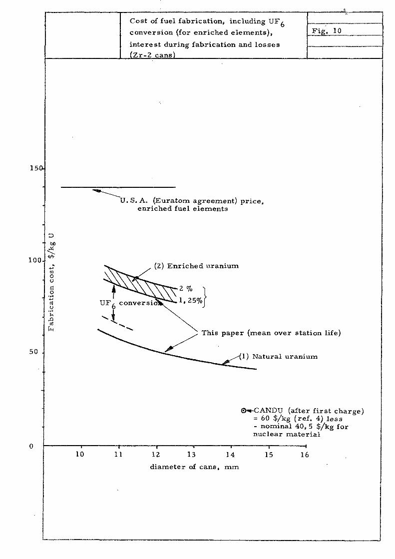
Cost of fuel fabrication, including
conversion (for enriched elements),
interest during fabrication and losses
(Zr-2 cans)
/Fig. 10
15a
U.S. A. (Euratom agreement) price,enriched fuel elements
100.< & •
taOuCo
•H
cdO
50 .
(2) Enriched uranium
U F
This paper (mean over station life)
1) Natural uranium
SKCANDU (after first charge)= 60 $/kg (ref. 4) less- nominal 40, 5 $/kg fornuclear material
10 11 12 13 14
diameter of cans, mm
15 16


steam drier
Saturated steam
Downcomer (Zr) in reflectorspace
Feed water, 195 C
Header for superheated steam(approx. 500 C for cans ofstainless steel
FIG. 11 Schematic diagram for D^O boiling reactor
(The broken lines show a possible way of adding superheat channels uniformlyspaced over the major part of the core to this type of reactor)


Natural circulation for D^O boiler as
function of coolant to fuel area ratio
Fig. 12
4)
oo
T3Si
cu
rves
for
öo4J
|
toto
<Joo
Xi
et w
hic
.t in
l
bO
ttli
0uXiH
a>u6<u?!
•—1
the
inf
to
ctj
73
1ou
hir
nn
e^ig
h c
xi
s00
I-H
<D
5̂O o
00
o
o
Volume percentage of voids at outlet of central channel


List of reports published in the AE-serles.
1. Calculation of the geometric buckling for reactors of variousshapes. By N- G. Sjöstrand. 1958. 23 p. Sw, Cr. 3:-
2. The variation of the reactivity with the number, diameter andlength of the control rods In a heavy water natural uraniumreactor. By H. Me Cririck. 1958. 24 p, Sw, (Jr. 3:-
3. Comparison of filter papers and an electrostatic preclpltatorfor measurements on radioactive aerosols. By R. Wiener. 1958.4 p. Sw. cr» 4j-
4. A slowing-down problem. By I. Carlvlk and B. Pershagen. 1958.Ik p. Sw. cr. Jr-
5. Absolute measurements with a 4 x-counter. (2nd rev. ed.). ByKerstin Martinsson. 1958. 20 p. Sw. cr. 4:-
6. Monte Carlo calculations of neutron thermallzation In aheterogeneous system. By T. Högberg. 1959. 13 p. Sw. or. 4:-
8. Metallurgical viewpoints on the brittleness of beryllium.By 0. Lagerberg, i960. 14 p. Sw. cr. 4:-
9. Swedish research on aluminium reactor technology. By B, Forsen,I960. 1? p. Sw. or. 4t-
10. Equipment for thermal neutron flux measurements In Reactor R2.By £. Johansson, T. Nilsson and 3. Claesson, i960. 9 p. Sw. cr. 6:-
11. Cross seotlons and neutron yields for U 2 ^ , U2"5^ and Pu2-5^at 2200 m/sec. By N.G. Sjöstrand and J.S. Story, i960. 34 p.Sw. cr. 4t-
12. Geometric buckling measurements using the pulsed neutron sourcemethod. By N.G. Sjöstrand, J. Mednls and T. Nilsson. 1959.12 p. Sw. cr, 4:-
1?, Absorption and flux density measurements in an iron plug in Rl.By R. Nilsson and J. Braun. 1958. 24 p. Sw, cr. 4:-
14. GARLIC, a shielding program for GAmraa Radiation from Line- andCylinder-sources. By M. Roos. 1959- 36 p. Sw. cr. 4:-
15. On the spherical harmonic expansion of the neutron angulardistribution function. By S. Depken. 1959. 53 P. Sw. or. 4t-
16. The Dancoff correction in various geometries. By I. Carlvikand B. Pershagen, 1959. 23 p. Sw, cr. 4:-
17. Radioactive nuolides formed by irradiation of the naturalelements with thermal neutrons. By K. Ekberg. 1959. 29 p.Sw. cr. 4i-
18. The resonance Integral of gold. By K. Jirlow and E. Johansson.1959. 19 P. Sw. cr. 4:-
19. Sources of gararaa radiation in a reactor core. By M. Roos. 1959*21 p. Sw. or. 4t-
20. Optimisation of gas-cooled reactors with the aid of mathematicalcomputers. By P. H. Margen. 1959. 33 P* Sw. er. 4:-
21. The fast fission effect in a cylindrical fuel element. By I. Carlvikand B. Pershagen. 1959* 25 p* Sw. cr. 4j-
22. The temperature coefficient of the resonance integral for uraniummetal and oxide. By P. Blomberg* E. Hel Is t rand and 3. Homer, i960.25 p. Sw. or. 4i-
23. Definition of the diffusion constant in one-group theory. ByN.O. Sjöstrand, i960. 8 p. Sw. cr. 4:-
25. A study of some temperature effects on the phonons in aluminium byuse of cold neutrons. By K-E. Larsson, U. Dahlborg and S. Holroryd.;*960. 32 P. Sw. cr, 4i-
26. The effect of a diagonal control rod in a cylindrical reactor.By T, Nilsson and N.O. Sjöstrand, i960. 4 p. Sw. cr. 4:-
28. RESEARCH ADMINISTRATION: A Selected and annotated bibliographyof recent literatur. By E. Rhenman and S. Svensson» I960.49 p. Sw, cr. 6:-
29. Some general requirements for irradiation experiments. Sy H.P. Myersand R. Skjöldebrand, i960. 9 p. Sw. cr. 6 : -
30. Metallographies Study of the Isothermal Transformation of BetaPhase In Zircaloy-2,' By G. Östberg, i960. 47 p. Sw. cr. 6 j -
32. Structure investigations of some beryllium materials. By I . Fäldtand Q, Lagerberg, i960. 15 P. Sw. cr . 6:-
33. An Emergency Dosimeter for Neutrons. 3y J . Braun and R. Nilsson,I960. 32 p. Sw. cr . 61-
35. The Multlgroup Neutron Diffusion Equations / l Space Dimension.By S. Linde. i960. 4l p . Sw. cr. 6s-
36. Geochemioal Frospeoting of a uraniferous bog deposit atMasugnsbyn, Northern Sweden. By G. Armands. 1961. Sw.cr. 61-
37. Speotrophotometric Determination of Thorium in LowGrade Minerals and Oxes. By A-L. Arnfelt and I . Edmundseon.1960. 14 p . Sw. Cr. 6t-
38. Kinetics of Pressurized Water Reactors with Rot or ColdModerators. By 0. Horinder. i960, Sw.Cr. 61-
39» The dependence of the resonance on the Soppier effeot.By J . Rosén. 1960. Sw. Cr. 61-
40. Measurements of the fast fission factor (e) in UO.-elementBBy 0. Nylund. 1960. Sw. or. 61-
44* Hand monitor for simultaneous measurement of alpha andbeta contamination. By I.Ö. Andersson, J . Braun and B.Söderlund. 1960. Sw.or. 61-
46. The magnetismuof HnB and i t s variation with the tempera-ture . By H* L ndquiet and H.P. Myers. 1<?60. Sw.or. 61-
47. An experimental study of the scattering of slow neutronsfrom H?0 and Sp0. By K.B. Larsson, 3 . Holmryd and E. Otnes.1960. Sw.or. 61-
48. The resonance integral of thorium metal rods. By B. Eell-atrand and J. Weitman. 1960. Sw.or. 61-
49. Pressure tube and pressure vessels reactors; certaincomparisons. 1961. By F.H. Margen, F.E. Ahlström andB. Pershagen. Sw.or. 6t-
^O. Phase transformations in a uranium-ziroonium alloy con-taining 2 weight per cent airoonium . By 0. Lagerberg.1961. Sw.or. 6t-
Additlonal copies available at the library of AB Atomenergi, Studsvik,Tystberga, Sweden. Transparent microcards of the reports are obtainablethrough the International Documentation Center, Turaba, Sweden.
Affärstryck, Stockholm 1961