pressure vessels -...
TRANSCRIPT
MODERN TECHNOLOGY SERVING THE GAS INDUSTRY
AND MUCH MORE
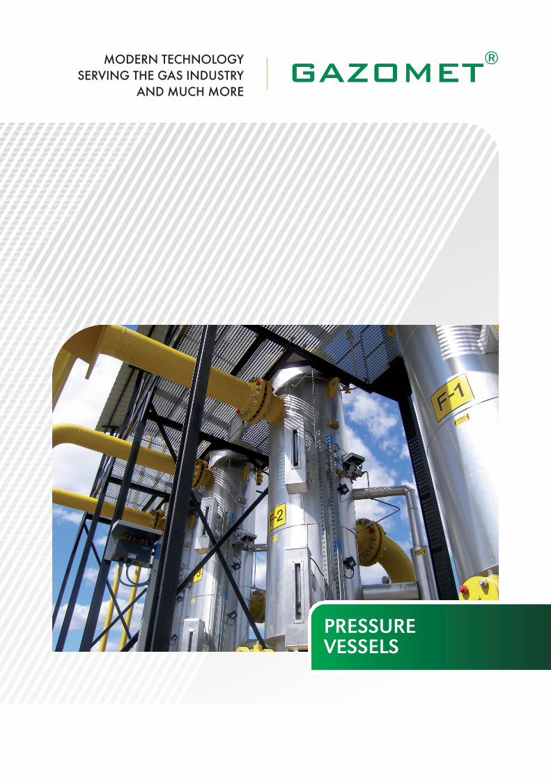
PRESSUREVESSELS

MODERN TECHNOLOGY SERVING THE GAS INDUSTRY AND MUCH MORE
1www.gazomet.pl
GAZOMET Sp. z o.o. was fo un ded in the year 1862. Sin ce1954, it has be en ma nu fac tu ring a va rie ty of pro ducts for thene eds of the Po lish gas in du stry. In 1969, GAZOMET de si gnedand ma nu fac tu red the first Po lish ball va lves for na tu ral gas. In1974 pro duc tion of me asu ring and re du cing gas sta tion waslaun ched, with ap pli ca tion of pres su re ves sels de si gned and ma -nu fac tu red in Ga zo met: gas fil ters, dust and li qu id se pa ra tors,gas he at exchan gers and com bi ned fil ter -he at exchan gers.
GAZOMET Sp. z o.o. is a spe cia li sed com pa ny, pro vi ding sta -te -of -the -art pro ducts for na tu ral gas and oil mi ning in du stry inPo land and abro ad, in ter alia for na tu ral gas trans mis sion pi pe li -nes and di stri bu tion pi pe li nes. Our pro ducts and so lu tions areal so ap plied in na tu ral gas and oil mi nes, and they me et all thestric test tech ni cal, eco lo gi cal and sa fe ty stan dards. Co ope ra -tion with se ve ral si gni fi cant com pa nies in Po land and abro ad en -su res a con ti nu es de ve lop ment of our pro ducts, which me ethigh expec ta tions of our cu sto mers.
GAZOMET Sp. z o.o. has im ple men ted and ma in ta ins qu ali tyma na ge ment sys tem PN-EN ISO 9001:2009 in the sco pe of sa -les, de sign, ma nu fac tu re, as sem bly, mo der ni za tion, re pa ir andse rvi ce of gas sta tions, pres su re re duc tion/me asu ring units, gasequ ip ment, pro tec ti ve lay ers PUR, pro cess and trans mis sion pi -pe li nes with the ir com po nents and ar ma tu re (in c lu ding ball va -lves), pres su re ves sels, gas odo ri zing sys tems, me asu ringde vi ces, ste el con struc tions and cra ne equ ip ment. ISO 9001cer ti fi ca te was is su ed by the UDT Urząd Do zo ru Tech nicz ne goin War saw.
GAZOMET Sp. z o.o. dec la res full com pa ti bi li ty of ma nu fac tu -red ar ma tu re with the Di rec ti ve PED 97/23/EC. Com pa ti bi li tywith re qu ire ments of PED 97/23/EC is ack now led ged by the“CE” mark pla ced on our pro ducts (UDT Urząd Do zo ru Tech -nicz ne go CE 1433).
GAZOMET Sp. z o.o. is a manufacturer of following pressurevessels:– standard (catalog) pressure vessels: filters, dust and liquid
separators, heat exchangers, combined filter-heatexchangers, – pig launchers and receivers, condensate tanks,– special vessels.
Pressure vessels are manufactured based on:– own standard technical documentation,– customer’s documentation,– technical documentation elaborated in conformity with
specific technical requirements, together with verification of the documentation and technical acceptance of the manufactured vessels executed by the Notified Body confirmed with “CE” marking.
All manufactured pressure vessels are subject to Directive PED97/23/EC and are manufactured with Notified Body (UDTCERT) supervision. The pressure vessels are marked with the“CE” sign.

2
Con struc tion and prin ci ple of ope ra tion
Gas fil ters ty pe F, FGP and FG equ ip ped with cel lu lo se car trid -ges are ma de as ste el we lded con struc tions. In de sign en gi ne -ering and strength cal cu la tions ap pro pria te re so lu tions andgu ide li nes of the UDT (Po lish Of fi ce of Tech ni cal In spec tion) for high -pres su re ves sels are ap plied, as well as the re qu ire mentsof the Di rec ti ve 97/23/EC.
The pre sen ted cross sec tion de mon stra tes the prin ci ple of fil ters’ ope ra tion. Con ta mi na ted gas flows in to the fil ter bo dythro ugh an in let pi pe. The fil ter’s con struc tion ena bles in i tial se pa ra tion of the he aviest so lid im pu ri ties which, in con se qu en -ce of gas spe ed re duc tion in the wi der sec tion of the fil ter, falldown, ac cu mu la ting in the lo wer part of the fil ter bo dy.
Gas wi tho ut the he aviest so lid im pu ri ties is di rec ted in to the cel -lu lo se fil ter car trid ge(s) and the re ma ining im pu ri ties are stop pedon the sur fa ce of the fil ter car trid ges.Fil ter flow ca pa ci ty is ad ju sted for gas flow thro ugh the fil ter car -trid ges not big ger than 2 m/s, whi le gas spe ed in in let and outletpi pes sho uld not exce ed 20 m/s.
Gas filters F, FGP, FG
Gas filter cross-section

MODERN TECHNOLOGY SERVING THE GAS INDUSTRY AND MUCH MORE
Dust and liquid separators FGWS
3www.gazomet.pl
In most tech no lo gi cal pro ces ses in which gas me dia are used,it is ne ces sa ry to use gas of high pu ri ty de gree. In ma ny ca ses,fil ters from GAZOMET’s port fo lio such as F, FGP or FG are suf -fi cient. Ho we ver, if gas is con ta mi na ted not on ly by so lid par tic -les, but al so by li qu id frac tion, im ple men ta tion of fil ters is notef fi cient. In such ca ses, two sta ge gas cle aning is ne ces sa ry,first sta ge to eli mi na te li qu ids and se cond sta ge to eli mi na te du -sts and so lid im pu ri ties . The FGWS dust and li qu id se pa ra torhas be en de si gned for this kind of ap pli ca tion.
Con struc tion and prin ci ple of ope ra tion
Dust and li qu id se pa ra tors are ma de in ver ti cal con fi gu ra tion.They are de si gned for se pa ra tion of so lid and li qu id par tic lesfrom gas stre am using its ki ne tic ener gy. As shown in the fi gu -re, a se pa ra tor is a ste el, we lded struc tu re. In de sign en gi ne eringand strength cal cu la tions ap pro pria te re so lu tions and gu ide li nesof the UDT (Po lish Of fi ce of Tech ni cal In spec tion) for high -pres -su re ves sels are ap plied, as well as the re qu ire ments of the Di -rec ti ve 97/23/EC. Se pa ra tion of li qu id par tic les ta kes pla ce inthe "wet cham ber" (the axial cyc lo ne), to which gas flows thro -ugh the in let pi pe, pas sing then in to the "dry cham ber", whe re itis fil te red from the so lid par tic les on cel lu lo se car trid ges.At the in let to the “wet cham ber“ gas is stron gly swir led by sta -tor va nes. A vor tex is in du ced, with gas ro ta ting spe ed in cre -asing to wards the swirl cen tre. In er tia for ces, ac ting on dust andflu id par tic les are ma ny ti mes hi gher than gra vi ty for ce. In thissi tu ation, con ta mi na tion par tic les are pu shed to wards the exter -nal wall of the se pa ra tor bo dy. Sin ce gas spe ed in the lay er ad -ja cent to the wall is small, in er tia for ces are re du ced and thegra vi ty for ce pull the flu id par tic les down to the bot tom of se -pa ra tor. A par ti tion, bu ilt -in at the half of the he ight of se pa ra -ting sec tion, pre vents any re pe ated en tra ining of col lec tedpar tic les by gas stre am. Fol lo wing this sta ge, gas stre am flowsupwards whe re it is pu ri fied by a fil ter car trid ge(s), and fi nal lyle aves the se pa ra tor bo dy thro ugh an outlet pi pe.
Fil tra tion ef fi cien cy
FGWS dust and li qu id se pa ra tors are cha rac te ri sed by a ve ryhigh ef fi cien cy of gas cle aning, com bi ning the fe atu res of cel lu -lo se car trid ges and axial cyc lo nes.Fil tra tion ef fi cien cy ra tes are: • for li qu id par tic les: 99.5 % for par tic les >10-12 µm • for so lid par tic les: 99.8 % for par tic les > 5 µm
(optio nal: 2 µm)
Dust and liquid separator FGWS - cross-section

4
PG he at exchan gers
Du ring gas pres su re re gu la tion, gas tem pe ra tu re drop ta kes pla -ce as a con se qu en ce of gas de pres su ri za tion (Jo ule -Thomp sonef fect). This ra pid tem pe ra tu re drop may cau se fro sting and evenfre ezing of re gu la tor units, espe cial ly of the re mo te con trol unitscon trol ling the pres su re re gu la tors mo un ted in high pres su re re -gu la tion sta tions. In or der to ma in ta in tro uble -free ope ra tion ofgas pres su re re gu la ting sta tions, it is ne ces sa ry to in cre ase gastem pe ra tu re prior to re gu la tion to as su re a gas tem pe ra tu re afterre gu la tion wi thin +5 to +10°C. One of the most com mon ly usedme thods of na tu ral gas he ating in pres su re re gu la ting sta tionsis ap pli ca tion of he at exchan gers, with hot flu id used as the he -ating me dium.Gas he ating is a re sult of he at trans fer be twe en the he ating me -dium and the gas flo wing thro ugh the tu be bun dle (co il). The he -ating me dium tem pe ra tu re in the he at exchan ger is con trol ledde pen ding on gas tem pe ra tu re do wn stre am the re gu la ting unit.Ad ding a cir cu la tion pump to the he ating me dium cir cu it im pro -ves he at trans fer and con trol’s ac cu ra cy. The cir cu la tion pumpin cre ases ef fi cien cy of he at exchan ging sur fa ce’s explo ita tion,and al lows to re du ce he ating me dium tu bes’ dia me ter.
Heat exchangers PG
Heat exchanger PG – cross-section

MODERN TECHNOLOGY SERVING THE GAS INDUSTRY AND MUCH MORE
5www.gazomet.pl
Pa ra me ters of he at exchan gers
In let (de sign) gas pres su re: stan dard – PN16, PN25, PN40,PN63, PN10 0He ating me dium:• wa ter (gly col so lu tion)• de sign pres su re of the he ating sec tion: stan dard:
PN6, PN63, PN10 0•in let tem pe ra tu re: +90°C,• outlet tem pe ra tu re: +70°C.
Sa fe ty equ ip ment
He at exchan gers are equ ip ped with a pi pe con nec tor lo ca tedon the shell si de, to con nect a sa fe ty equ ip ment. If tu be is da ma ged, the gas may be im me dia te ly ven ted in to the at mo -sphe re, either via a sa fe ty he ad or sa fe ty va lve. In stan dard ap -pli ca tions, the pi pe con nec tor is de si gned with a flat flan gePN16 B1 acc. EN 1092-1. When the shell si de’s de sign pres -su re is the sa me as gas sec tion’s de sign pres su re, sa fe ty is pro -vi ded by ap pli ca tion of RMG 790 va lves, set for the ma xi malpres su re of the he ating flu id in the bo iler sys tem. The gas esca -ping thro ugh the da ma ged tu be is cap tu red in si de the shell si deof the he at exchan ger, as the RMG 790 va lves clo se the in letand outlet of he ating me dium.
Con struc tion and prin ci ple of ope ra tion
He at exchan gers in the ba sic con fi gu ra tion ha ve a co il, we ldedin to a mesh bot tom, lo ca ted be twe en the tu be si de flan ge andthe he ating me dium jac ket flan ge. The se parts may, at any ti me,be in di vi du al ly re pla ced. Cold gas flows thro ugh the in let pi pein to the co il. After be ing he ated du ring trans port thro ugh the co -il, gas le aves the he at exchan ger thro ugh the outlet pi pe. Thehe ating me dium flows thro ugh a num ber of baf fles, le ading it ro -und the co il. The tu be bun dles are we lded in to a mesh bot tom,de si gned (cal cu la ted) ac cor din gly to the gas pres su re.The tu be si de of the he at exchan ger is equ ip ped with con nec -tor pi pes for dra ining con den sa te. The mesh bot tom is equ ip -ped with a dra in va lve to dra in re ma ins of he ating me dium wi thinthe spa ce be low the outlet con nec tor.
Heat exchangers PG
Heat exchanger PG with RMG 790 valves – cross-section

6
Con struc tion and prin ci ple of ope ra tion
FGWC com bi ned fil ter -he at exchan gers com bi ne the func tionsof gas fil ters with cel lu lo se fil ter car trid ges, with gas he atexchan gers. They are de si gned as we lded ste el con struc tions.Be low cross -sec tion il lu stra tes the prin ci ple of ope ra tion of com -bi ned fil ter -he at exchan ger. Con ta mi na ted gas flows in to theFGWC bo dy via a in let pi pe, and as a re sult of gas flow ve lo ci -ty de cre ase, lar ger con ta mi nants fall down to the bot tom of thetu be si de. Other con ta mi na tion par tic les are se pa ra ted whi le gasflows thro ugh the fil ter car trid ge. Cle an gas is di rec ted from thein ner part of the car trid ge in to a pi pe sys tem (co il), im mer sed ina hot bath (whe re it is he ated) and then, to the outlet pi pe.
Sa fe ty equ ip ment
Com bi ned fil ter -he at exchan gers are equ ip ped with a pi pe con -nec tor lo ca ted on the shell si de, to con nect a sa fe ty equ ip ment.If tu be is da ma ged, the gas may be im me dia te ly ven ted in to theat mo sphe re, either via a sa fe ty he ad or sa fe ty va lve. In stan dardap pli ca tions, the pi pe con nec tor is de si gned with a flat flan gePN16 B1 acc. EN 1092-1. When the shell si de’s de sign pres -su re is the sa me as gas sec tion’s de sign pres su re, sa fe ty is pro -vi ded by ap pli ca tion of RMG 790 va lves, set for the ma xi malpres su re of the he ating flu id in the bo iler sys tem. The gas esca -ping thro ugh the da ma ged tu be is cap tu red in si de the shell si deof the he at exchan ger, as the RMG 790 va lves clo se the in letand outlet of he ating me dium.
Combined filter-heat exchangers FGWC
Combined filer-heat exchanger FGWC – cross-section

MODERN TECHNOLOGY SERVING THE GAS INDUSTRY AND MUCH MORE
7www.gazomet.pl
Filter cartridges GD
In the ir stan dard ver sion, gas fil ters and dust and li qu id se pa ra -tors are equ ip ped with cel lu lo se fil ter car trid ges of GD ty pe. These pa ra tion of so lid par tic les from the gas is held in a star -ple -ated, im pre gna ted in sin gle -sta ge re sin, cel lu lo se pa per she et.This con struc tion ma kes the car trid ge re si stant to mo istu re andme cha ni cal da ma ge, for exam ple to te ar. In com pa ri son to feltcar trid ges, cel lu lo se car trid ges pro vi de 4.5 ti mes gre ater ac ti vefil te ring area. Both the in ter nal and the exter nal si de of the fil te -ring ma te rial is pro tec ted with per fo ra ted me tal she et.
The pho to be low shows car trid ges pro tec ted with ga lva ni sedshe et. Car trid ges of this ty pe are not re si stant aga inst ag gres si -ve agents li ke bio gas. Ag gres si ve or so ur and acid ga ses are fil -te red with car trid ges pro tec ted with sta in less ste el me tal she et.Both he ads of the fil ter car trid ges are equ ip ped with felt rings,se pa ra ting con ta mi na ted gas si de and cle an gas si de of the fil -ter or dust and li qu id se pa ra tor. The di men sions of GAZOMET’sfil ter car trid ges are pre sen ted in the ta ble.Fil ter car trid ges for stan dard ap pli ca tions (GD and GDW) se pa -ra te par tic les ø 5 µm, whi le optio nal con fi gu ra tions (GC andGCW) se pa ra tes par tic les ø 2 µm.
Filter cartridges GD, GDW
Cellulose filter cartridges
GD
Typem2 mm
Area D d H
GD 0,1 0,2 62 42,5 108
GD 1 0,8 98 46 180
GD 1,5 1,1 122 62 220
GD 2 1,4 165 114 260
GD 3 3 250 194 320
GDW
Typem2 mm
Area D d H
GD3W2 9 250 194 640
GD4W2 15 282 220 800
GD5W2 21 340 270 800

8
Exa mi na tion, te sts and ac cep tan ce of pres su re ves sels
Ac cor ding to re gu la tions of the UDT and Tech ni cal Stan dardsof the ICG (Cham ber of the Na tu ral Gas In du stry)
Pre se rva tion of pres su re ves sels
All pres su re ves sels and pi pes, sub mit ted for ac cep tan ce, shallha ve the ir sur fa ce me tal -cle an. Fol lo wing po si ti ve ac cep tan ce,the outer sur fa ces are pri med with epo xi de pa ints, fol lo wed byco ating with fi nal epo xi de pa int of yel low co lo ur.
Ma te rials used for pro duc tion
In the ir stan dard ver sion, pres su re ves sels and pi pes are ma deof ma te rials, se lec ted on the ba sis of con trol strength cal cu la -tions and ap pro ved by the UDT (Po lish Of fi ce of Tech ni cal In -spec tion) for gi ven no mi nal pres su re ap pli ca tions.
All ba sic ma te rials ha ve me tal lur gi cal cer ti fi ca tes, and the ma infil ter com po nents ha ve got stam ped ma te rial ty pe and he atnum ber.
Examination, tests and acceptance of pressure vessels

www.gazomet.ple-mail: [email protected]
BALL VALVES
BALL VALVES METAL-METAL
GAS STATIONS
BOILER ROOMS
GAS OBJECTS
PIPE SPOOLS
GAS FILTERS
DUST AND LIQUID SEPARATORS
HEAT EXCHANGERS
COMBINED FILTER-HEAT EXCHANGERS
PIG LAUNCHERS AND PIG RECEIVERS
TECHNICAL TRAININGS
AFTERSALE SERVICE
................................................................................
................................................................................
................................................................................
................................................................................
................................................................................
................................................................................
................................................................................
................................................................................
................................................................................
................................................................................
................................................................................
................................................................................
................................................................................
GAZOMET Sp. z o.o., ul. Sarnowska 2, 63-900 Rawicz, tel.: +48 65 545 02 00, fax: +48 65 546 24 08 04/15