prestressed concrete structures -...
TRANSCRIPT

PRESTRESSED CONCRETE STRUCTURES
Amlan K. Sengupta, PhD PE
Department of Civil Engineering
Indian Institute of Technology Madras
Module – 5: Analysis and Design for Shear and Torsion
Lecture-24: Design for Shear (Part 1)
Welcome back to prestressed concrete structures. This is the second lecture of Module 5
on analysis and design for shear and torsion. In this lecture, we shall study about the
design for shear. First, we shall study about the limit state of collapse for shear; next, we
shall move on to maximum permissible shear stress; then we shall move on to design of
transverse reinforcement; finally, we shall look into detailing requirements for shear.
(Refer Slide Time 01:45)
First, limit state of collapse for shear. In the last lecture, I mentioned that when we study
shear, we study the strength at ultimate. We do not use the principles of compatibility of
strains or the constitutive relationships for the stress-strain behaviour of concrete or steel.
We use an equilibrium equation that is based on the ultimate strength of the concrete

under flexural shear. The total shear capacity of the member is the summation of the
capacity of concrete and that of steel.
(Refer Slide Time 03:12)
The ultimate resistance of a section, which is represented as VuR consists of a concrete
contribution Vc and the stirrup contribution Vs. Thus, VuR = Vc + Vs. Here, Vc includes
Vcz which is the contribution from uncracked concrete, Va which is the aggregate
interlock, and Vd which is the dowel action. Last time, when we studied the components
of shear resistance, we found that for a prestressed concrete section, the components of
shear resistance are Vcz, Va, Vd, and Vs. If the tendon is inclined, then we get a vertical
component of the prestressing force, which is represented as Vp. Three of these
components are grouped together under the contribution of concrete, which is represented
as Vc. Thus, now we are having three components: one is Vc, another is Vs, and when the
tendon is inclined we include Vp.

(Refer Slide Time 04:32)
The value of Vc depends on whether the section is cracked due to flexure or not. Section
22.4 of IS: 1343 - 1980, gives two expressions of Vc: one for cracked section, and the
other for uncracked section. Last time, we had studied that when the concrete member is
loaded, first the flexural cracks are initiated. Next, the flexural cracks tend to become
flexure‒shear cracks. As we move away from the mid-span, we may find some
flexure‒shear cracks developing.
The shear strength of concrete depends on whether the section has cracked or not. The
code says that we need to calculate the shear capacity of concrete from two expressions.
One expression is given for the cracked section, and the other expression is given for an
uncracked section. Both the expressions need to be evaluated at a particular section, and
the lower value obtained from the two expressions is selected. Usually, the expression for
the uncracked section will govern near the support. The expression for the cracked
section will govern near the mid-span.

(Refer Slide Time 06:10)
Usually, for a beam under a uniformly distributed load, cracks generate near mid-span
and in that region the expression for the uncracked section will govern. For the portions
near the support, cracks may not develop. Usually, the expression for uncracked section
will govern in that region.
(Refer Slide Time 07:24)
Next, we are moving on to the two expressions for Vc. For uncracked section, Vc = Vc0,
where Vc0 is expressed as 0.67bD √(ft2 + 0.8 fcp ft). Vc0 is the shear causing web shear

crack at CGC. Thus, the capacity of concrete for an uncracked section is the value of
shear which causes a web shear crack near the support. This expression can be derived
from the concept of Mohr’s circle.
(Refer Slide Time 07:51)
In this expression, b is equal to breadth of the section, which is equal to bw, the breadth of
the web for flanged sections; D is the total depth of the section which we have
represented as h in earlier occasions; ft is the direct tensile strength of concrete which is
0.24√fck; fcp is the compressive stress in concrete at CGC due to the prestress, which is
equal to Pe/A. We are considering the numeric value of fcp; actually fcp is compressive,
but we are taking only the numeric value of fcp in the expression.

(Refer Slide Time 09:01)
The previous equation can be derived based on the expression of the principal tensile
stress 1 at CGC. If we take an element at the CGC, then there is a shear stress (v) and a
compressive stress (fcp) at the vertical face. This state of two dimensional stresses can be
transformed to a state of principal stresses, where 1 is the principal tensile stress and 2
is the principal compressive stress. If we plot the Mohr’s circle, the point corresponding
to the vertical face of the element has coordinates (‒ fcp, v). The point corresponding to
the horizontal face is on the vertical axis, with no normal stress, but with a shear stress of
v.
We observe that the value of 1 is much smaller than the magnitude of 2. This is due to
the prestressing force. The value of 1 can be calculated if we are able to locate the origin
of the circle. The origin of the circle is at (‒fcp/2, 0). The distance of 1 from the origin is
the radius of the circle, which is equal to √((‒fcp/2)2 + v
2). Thus, 1 = ‒fcp/2 + √(fcp
2/4 +
v2).
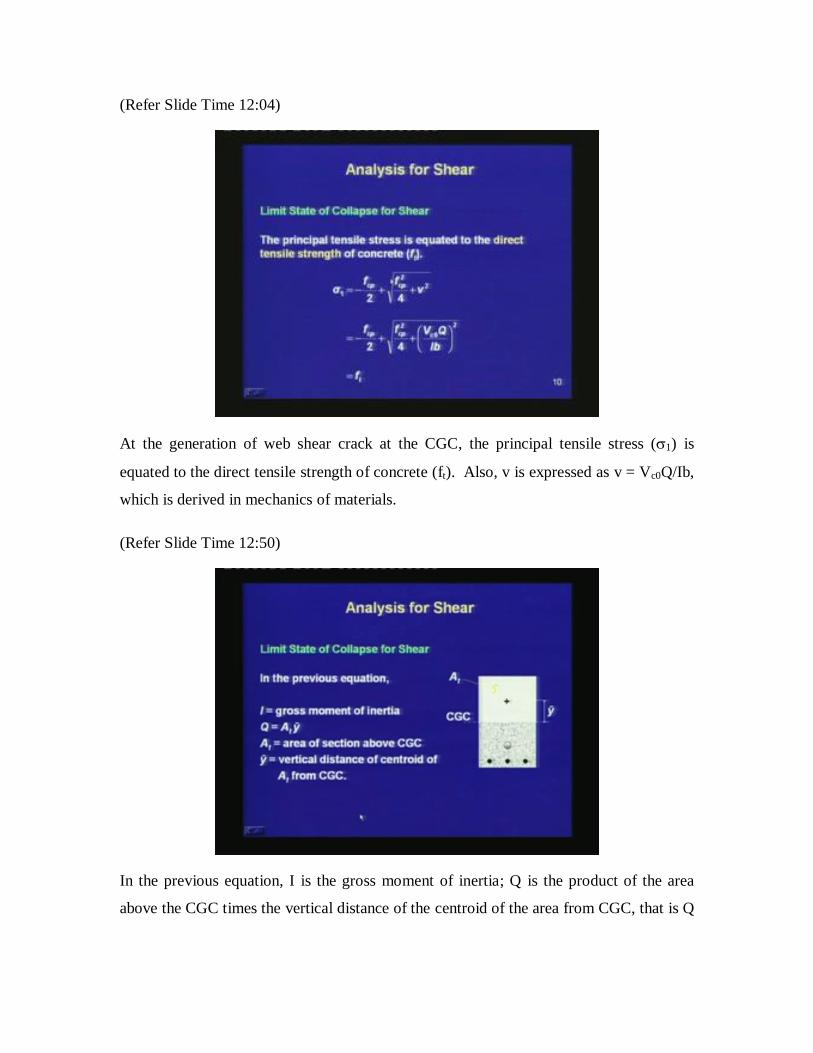
(Refer Slide Time 12:04)
At the generation of web shear crack at the CGC, the principal tensile stress (1) is
equated to the direct tensile strength of concrete (ft). Also, v is expressed as v = Vc0Q/Ib,
which is derived in mechanics of materials.
(Refer Slide Time 12:50)
In the previous equation, I is the gross moment of inertia; Q is the product of the area
above the CGC times the vertical distance of the centroid of the area from CGC, that is Q
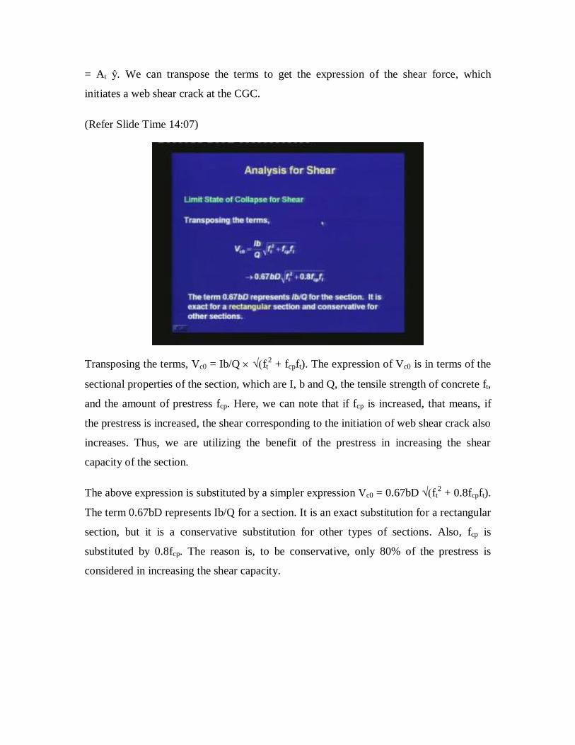
= At ŷ. We can transpose the terms to get the expression of the shear force, which
initiates a web shear crack at the CGC.
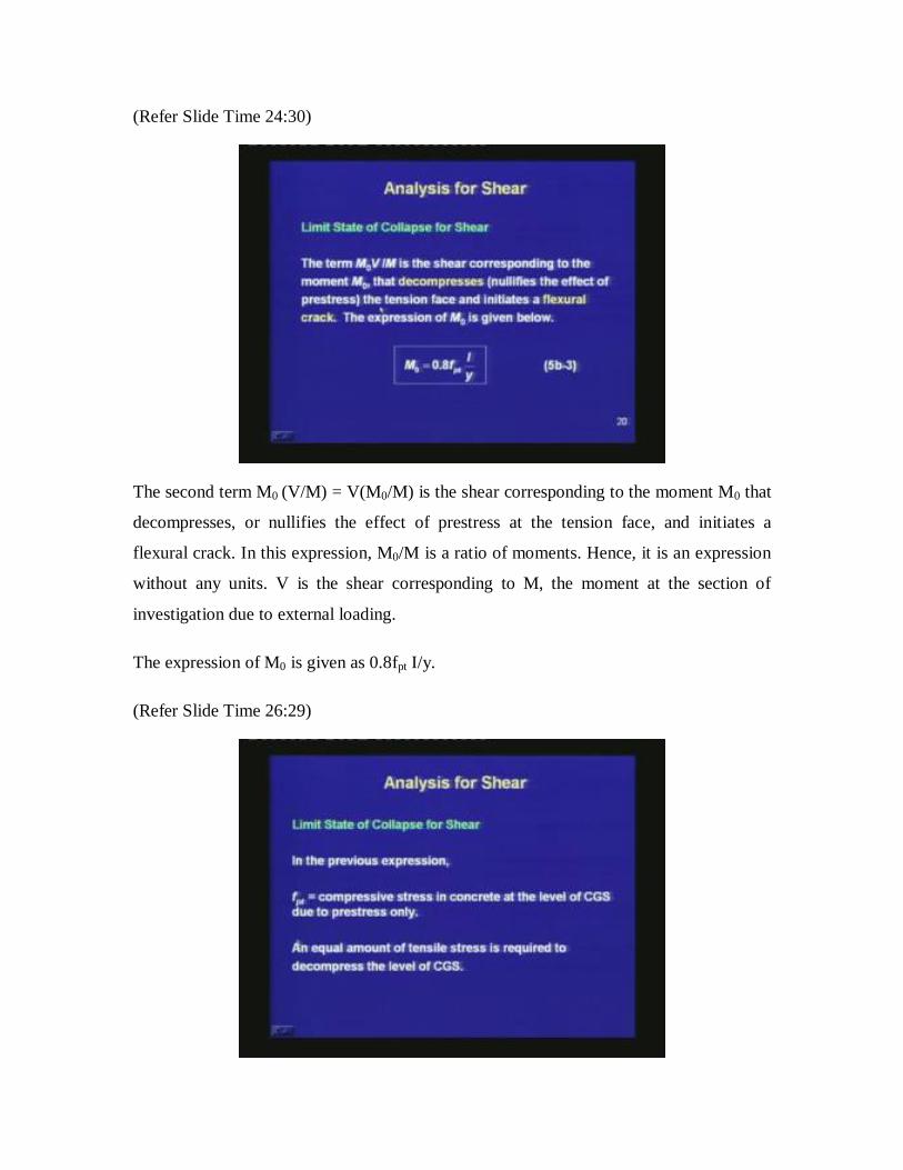
(Refer Slide Time 14:07)
Transposing the terms, Vc0 = Ib/Q √(ft2 + fcpft). The expression of Vc0 is in terms of the
sectional properties of the section, which are I, b and Q, the tensile strength of concrete ft,
and the amount of prestress fcp. Here, we can note that if fcp is increased, that means, if
the prestress is increased, the shear corresponding to the initiation of web shear crack also
increases. Thus, we are utilizing the benefit of the prestress in increasing the shear
capacity of the section.
The above expression is substituted by a simpler expression Vc0 = 0.67bD √(ft2 + 0.8fcpft).
The term 0.67bD represents Ib/Q for a section. It is an exact substitution for a rectangular
section, but it is a conservative substitution for other types of sections. Also, fcp is
substituted by 0.8fcp. The reason is, to be conservative, only 80% of the prestress is
considered in increasing the shear capacity.

(Refer Slide Time 16:22)
The expression that we have derived is based on the stress at the level of CGC, being
equal to the tensile strength of concrete.
(Refer Slide Time 17:02)
For a flanged section, when the CGC is in the flange, the intersection of web and flange
is considered to be the critical location for the generation of web shear cracks. Hence,
substitute 0.8fcp by the term 0.8 times the stress in concrete at the level of the intersection

of web and flange. This stress can be found out by the elastic analysis that we had studied
under the analysis of sections for flexure.
(Refer Slide Time 18:34)
In presence of inclined tendons or vertical prestress, the vertical component of the
prestressing force Vp can be added to Vc0. Thus, the total strength can be considered as
Vc0 = 0.67bD √(ft2 + 0.8fcpft) + Vp.

(Refer Slide Time 20:45)
Next, we are studying the expression of Vc for a cracked section. This expression is more
involved because the cracking of concrete is inherently variable in nature. The cracks are
first generated due to flexure and then, they propagate due to shear. The expression of Vc
is equated to Vcr, where Vcr is the shear corresponding to flexure‒shear cracking. The
earlier term Vc0 was for web shear cracking, whereas Vcr is for flexure‒shear cracking.
Vcr = (1 ‒ 0.55 fpe/fpk)c bd + M0 (V/M). Vcr need not be less than 0.1bd√fck.
In the above expression there are two terms. The first term is the additional shear that
changes a flexural crack to a flexure‒shear crack. The second term M0 (V/M) = V(M0/M)
is the shear corresponding to the generation of a flexural crack at the bottom of the beam.

(Refer Slide Time 21:31)
The first term is an empirical expression. The notations are as follows: fpe is the effective
prestress in the tendon after all losses and it should be less than or equal to 0.6 fpk; c is
the ultimate stress capacity of concrete which is obtained from Table 6 of IS: 1343 –
1980.
(Refer Slide Time 21:56)
The values of c are plotted in this graph. It is given in terms of the amount of
prestressing steel. The graphs are given for two grades of concrete M30 and M40. We

observe that as the amount of the prestressing steel is increasing, the strength of the
concrete is also increasing; but, it gradually tapers off to a constant value. There is not
much difference between the values for the two grades of concrete. From this we can
infer that the strength of the concrete under shear even for a cracked section, increases
with the amount of the prestressing steel.
Even for the cracked region, since the prestressing steel applies a compression, the
growth of crack is reduced, the depth of concrete under compression is increased, the
aggregate interlock is increased, and the bond between the longitudinal steel and concrete
is retained to generate dowel action. Hence, the strength of concrete under shear for a
cracked section increases with the amount of prestressing steel.
(Refer Slide Time 24:03)
In the expression, b is the breadth of the section, which is equal to bw the breadth of the
web for a flanged section, and d is the distance from the extreme compression fibre to the
centroid of the tendons at the section considered.
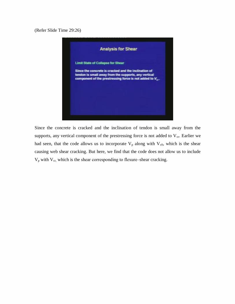
(Refer Slide Time 24:30)
The second term M0 (V/M) = V(M0/M) is the shear corresponding to the moment M0 that
decompresses, or nullifies the effect of prestress at the tension face, and initiates a
flexural crack. In this expression, M0/M is a ratio of moments. Hence, it is an expression
without any units. V is the shear corresponding to M, the moment at the section of
investigation due to external loading.
The expression of M0 is given as 0.8fpt I/y.
(Refer Slide Time 26:29)

In the previous expression, fpt is the compressive stress in concrete at the level of CGS
due to prestress only. An equal amount of tensile stress is required to decompress the
level of CGS.
(Refer Slide Time 27:31)
In the expression of M0, y is the depth of the CGS from CGC. The expression is actually
80% of fpt I/y, the moment that causes decompression of the concrete at the level of CGS.
To recollect, M0 is the moment corresponding to the decompression of the tension face,
which occurs earlier. Hence, M0 is taken as 80% of that moment which causes
decompression at the level of CGS.
(Refer Slide Time 29:26)
Since the concrete is cracked and the inclination of tendon is small away from the
supports, any vertical component of the prestressing force is not added to Vcr. Earlier we
had seen, that the code allows us to incorporate Vp along with Vc0, which is the shear
causing web shear cracking. But here, we find that the code does not allow us to include
Vp with Vcr, which is the shear corresponding to flexure‒shear cracking.

(Refer Slide Time 31:23)
Next, let us learn the maximum permissible shear stress in concrete. As mentioned in the
last lecture, there are several modes of shear failure. The approach in shear design is that,
we design the reinforcement as per the requirement based on the capacity of concrete to
take shear. We also do some other checks and satisfy detailing requirements to avoid
other modes of failure. The maximum permissible shear stress in concrete is one way to
check the crushing of concrete in shear compression failure.
The shear stress is limited to a maximum value which is represented as c,max. The value
of c,max depends on the grade of concrete and is given in Table 7 of IS: 1343-1980. The
nominal shear stress, Vu/bdt should be less than c,max. This is to avoid a brittle shear
compression failure.

(Refer Slide Time 32:22)
In the previous expression, b is the breadth of the section, dt is the greater of dp or ds,
where dp is the depth of the CGS from the extreme compression fiber, ds is depth of
centroid of regular steel, Vu is the shear force at a section due to ultimate loads. Thus,
whenever we are doing this shear check, we are calculating the average shear stress based
on the depth, which is larger of the depth of the CGS and the depth of the non-prestressed
steel. This larger value is denoted as dt.
(Refer Slide Time 33:16)

When the values of c,max from Table 7 are plotted, their variation is as shown in the
graph. For different grades of concrete, c,max slightly increases and more or less it
stabilizes when we reach a concrete strength of 60 N/mm2.
To check web crushing failure, the Indian Roads Congress code IRC 18-2000 specifies
minimum thickness of the web for a T-section in Clause 9.3.1.1. The minimum thickness
is 200 mm plus diameter of the duct hole. This provision is not there in IS: 1343-1980.
But, it is advisable to maintain a minimum width of the web to avoid web crushing
failure for a flanged section.
(Refer Slide Time 34:48)
Next, let us look into the design of transverse reinforcement in more details. When the
shear demand Vu exceeds the shear capacity of concrete which is denoted as Vc,
transverse reinforcements in the form of stirrups are required. The stirrups resist the
propagation of diagonal cracks, checking both the diagonal tension failure and shear
tension failure. The diagonal tension failure occurs when a diagonal crack propagates
rapidly through the depth of the section.

(Refer Slide Time 36:01)
In a shear tension failure, the diagonal crack merges with the horizontal crack at the level
of the bottom longitudinal bars. The crack propagates towards the support and the
longitudinal bars lose their anchorage. To resist both these types of failures, we need
shear reinforcement which will traverse the diagonal cracks. The stirrups resist a failure
due to shear by several ways.
(Refer Slide Time 36:28)

The functions of stirrups are listed below: first, stirrups resist part of the applied shear
which is denoted as Vs; second, they restrict the growth of diagonal cracks; third, the
stirrups counteract the widening of the diagonal cracks, thus maintaining aggregate
interlock to a certain extent; fourth, the splitting of concrete cover is restrained by the
stirrups, by reducing dowel forces in the longitudinal bars.
Thus, the contribution of the stirrups is not only in Vs, but it has a contribution in Vc as
well. For the different reasons, stirrups are mandatory for a reinforced concrete or a
prestressed concrete beam.
(Refer Slide Time 39:01)
After cracking, the beam is viewed as a plane truss. The top chord and the diagonals are
made of concrete struts and the bottom chord and the verticals are made of steel
reinforcement ties. Based on this truss analogy, the total area of the legs of the stirrups
which is represented as Asv is given as follows.
Asv / sv = (Vu ‒ Vc) / 0.87fy dt
Vu is the shear demand. From this, we are subtracting the concrete contribution Vc. Vc
can be calculated for a particular section from the expressions of Vcr or Vc0, whichever
gives the lower value. Subtracting Vc from Vu, we get the required value of Vs. Then,
from the truss analogy, we can write the expression of Asv / sv. We are not going into the

details of the truss analogy here. The angle of inclination of the cracks is considered to be
45.
(Refer Slide Time 40:40)
The notations in the previous equation are as follows: sv is the spacing of the stirrups, dt
is the effective depth which is greater of dp or ds where dp is the depth of CGS from the
extreme compression fibre and ds is the depth of centroid of the longitudinal steel, fy is
the characteristic yield strength of the stirrups. The maximum stress in the stirrups is
limited to 0.87fy. The grade of steel for stirrups should be restricted to Fe 415 or lower.
That means, the code does not allow a grade of steel greater than Fe 415 because
traditionally such a grade has less yielding.

(Refer Slide Time 42:08)
For design, if Vu is less than Vc, theoretically we do not need stirrups. But the code says
that we have to provide a minimum amount of transverse reinforcement which is based
on the following equation.
Asv / bsv = 0.4/0.87fy
This equation is derived by assuming that the stirrups should have a minimum stress of
0.4 N/mm2.

(Refer Slide Time 42:35)
Here, b is the breadth of the section which is equal to bw the breadth of the web for
flanged sections. If Vu is less than 0.5 Vc and the member is of minor importance, stirrups
may not be provided. That means, the code gives us some freedom that if the shear
demand is half of the shear capacity of concrete and the member is of minor importance,
in that situation we may not provide stirrups. Otherwise we have to provide stirrups. If Vu
is less than Vc, we have to provide the minimum amount of stirrups.
(Refer Slide Time 43:12)
Next, let us look at the detailing requirements. The detailing requirements for the stirrups
in IS: 1343 -1980 are briefly mentioned.
(Refer Slide Time 43:19)
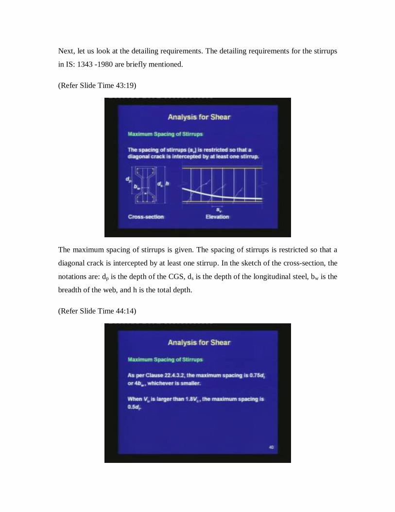
The maximum spacing of stirrups is given. The spacing of stirrups is restricted so that a
diagonal crack is intercepted by at least one stirrup. In the sketch of the cross-section, the
notations are: dp is the depth of the CGS, ds is the depth of the longitudinal steel, bw is the
breadth of the web, and h is the total depth.
(Refer Slide Time 44:14)

The maximum spacing is given in Clause 22.4.3.2. It is equal to 0.75dt or 4bw whichever
is smaller. Thus, the maximum spacing is the smaller value of 75% of the value of dt or 4
times the breadth of the web. If the shear demand Vu is high, if it crosses 1.8 times Vc,
then the maximum spacing is reduced to 0.5 times dt. Thus, for higher values of Vu the
stirrup spacing is even restricted.
(Refer Slide Time 45:00)
The variables are: bw is the breadth of the web, dt is greater of dp or ds, dp is depth of CGS
from extreme compression fiber, ds is depth of centroid of non-prestressed steel, Vu is the
shear force at a section due to ultimate loads, Vc is the shear capacity of concrete which is
determined from Vc0 or Vcr.

(Refer Slide Time 45:20)
A minimum amount of stirrups is necessary to restrict the growth of diagonal cracks and
subsequent shear failure. As per Clause 18.6.3.2, stirrups are recommended for beams
with thin webs. The minimum amount of stirrups is given in terms of Awh, the horizontal
sectional area of the web in plan.
(Refer Slide Time 46:10)
The area is shown in this figure. If we take a horizontal section, then Awh is the area of
the web for this horizontal section.

(Refer Slide Time 46:31)
In the presence of dynamic load, minimum amount of Asv (Asv,min) is equal to 0.3% of
Awh, which can be lowered to 0.2% Awh, when h is less than or equal to 4bw. With high
strength bars, Asv,min is equal to 0.2%Awh which can be lowered to 0.15%Awh, when h is
less than or equal to 4bw.
(Refer Slide Time 46:55)
In the absence of dynamic load, when h is greater than 4bw, then Asv,min is equal to 0.1%
of Awh. There is no specification of Asv,min when h is less than or equal to 4bw. Thus, we

find that there are two requirements of minimum amount of stirrup. One is based on the
truss concept that the stirrups have to take a minimum amount of shear stress. The other
expression is for beams with thin webs, given in terms of the horizontal section of the
web.
(Refer Slide Time 47:49)
The stirrups should be anchored to develop the yield stress in the vertical legs. This is
very important that we anchor the stirrups properly, so that it can develop the yield stress
at ultimate.

(Refer Slide Time 48:00)
The stirrups should be bent close to the compression and tension surfaces, satisfying the
minimum cover. That means the stirrups should run throughout the full depth as much as
possible. The stirrups should be bent around the top steel and the bottom steel. Each bend
of the stirrups should be around a longitudinal bar. The diameter of the longitudinal bar
should not be less than the diameter of the stirrups.
(Refer Slide Time 49:06)

In order to maintain the bend in the stirrups, the diameter of the longitudinal bar has to be
at least equal to the diameter of the stirrup. The end of the stirrups should be anchored by
standard hooks. The specifications for the hooks are given in handbook on detailing.
There should not be any bend in a re-entrant corner. In a re-entrant corner, the stirrup
under tension has the possibility to straighten, thus, breaking the cover concrete. Let us
understand this with the help of a sketch. The following sketches explain the requirement
of avoiding the bend of a stirrup at a re-entrant corner.
(Refer Slide Time 49:21)
In a re-entrant corner, if we provide a single stirrup, then the stirrup tends to straighten
out. It tends to break the concrete near the re-entrant corner. This detailing is incorrect.
The correct detailing is that, we have to provide two pieces of stirrups. None of them has
any bend near the re-entrant corners and hence, does not pose a threat of breaking the
concrete near the corners.

(Refer Slide Time 50:11)
Today, we studied the design for shear. First, we studied the limit state for shear. As we
had said earlier, that in shear analysis and design, we do not consider the complete
behaviour. The design is based on the ultimate strength of the section under shear. This
strength, which is represented as VuR is a summation of Vc and Vs, where Vc is considered
to be the contribution of the concrete, and Vs is the contribution of the stirrups. In Vc, we
are placing all the three individual components: the contribution of uncracked concrete
under compression is represented as Vcz, the aggregate interlock is represented as Va, and
the dowel action is Vd. All these three are clubbed together in the expression of Vc. The
code gives us two expressions of Vc: one for uncracked section and the other for a
cracked section. The uncracked section expression usually governs the region near the
supports, and the cracked section expression usually governs the region near the mid-
span.
When a beam is loaded, first, we observe flexural cracks near the mid-span. Then, the
flexural cracks away from the mid-span tend to bend due to the effect of shear. These
types of cracks are called flexure shear cracks. Then, with further increase in the load, we
may have cracks near the centroid of the section close to the supports. Those cracks are
inclined and are called web shear cracks.

The shear strength of uncracked concrete is given as the shear force which initiates a web
shear crack at the level of CGC. The expression of Vc = Vc0 is derived from the concept
of Mohr’s circle of stress at the level of CGC.
For a point at the level of CGC, there is a shear stress. Along with that, for a prestressed
concrete beam there is a normal compressive stress which we are denoting as fcp. From
the values of V and fcp, we can write the expression of the principal tensile stress 1 based
on the Mohr’s circle. Then we equate 1 to the direct tensile strength of concrete which is
denoted as ft.
Once we write this expression, we can substitute the shear stress v = Vc0Q/Ib. After
transposing the terms, we get an expression of Vc0. In this expression, fcp is reduced to
80% to stay conservative. If we have a flanged section, then the code recommends that
the crack may initiate at the level of the intersection of the web and the flange. Hence,
0.8fcp should be substituted by 0.8 times the stress in the concrete at the level of
intersection of web and the flange.
The second expression for Vc is based on a cracked section, where Vc = Vcr consists of
two terms. The first term is the shear that propagates flexural crack to a flexure shear
crack. This expression is in terms of the prestressing force fpe and the capacity of
concrete, which is given as c. The capacity of concrete c increases with the amount of
prestressing steel, because the more prestressing steel we have, we have a reduced length
of the flexure shear cracks, we have more concrete under compression, there will be more
aggregate interlock, and a better dowel action. Hence, the capacity of concrete is
increased with the amount of prestressing steel.
The second term of Vcr is the shear corresponding to the generation of a flexural crack at
the bottom of the beam. This is based on the ratio of the moments M0/M, where M0 is the
moment required to generate a flexural crack at the bottom and M is the moment demand
based on service loads.
We can have both V and M as the demands based on ultimate loads, because the load
factors anyhow will cancel out from the numerator and the denominator. M0V/M denotes

the shear, which corresponds to the generation of a flexural crack at the bottom of the
beam. Thus, Vcr consists of two terms: the first term is a shear which extends a flexural
crack to a flexure shear crack. The second one is the shear which is needed for a
generation of a flexural crack at the bottom of the beam.
Once we have learned these two expressions of Vc0 and Vcr, we can calculate Vc as the
lower of these two values at any particular section. We can add Vp to Vc, if the tendon is
inclined and this is allowed only with the expression of Vc0. Once we have calculated Vc,
we can subtract this from Vu, the shear demand and get the required value of Vs. The
amount of steel and the spacing of the stirrups are given by an expression which is based
on the truss analogy for shear. This is in terms of Vs and the maximum stress that can be
generated in the stirrups equal to 0.87fy. The code recommends to provide a minimum
amount of stirrups even if Vu is less than Vc. That is based on a certain minimum stress to
generate within the stirrups. The code also gives another expression of minimum amount
of stirrups which is applicable for beams with thin webs. The values are given in the
presence of dynamic load and in the absence of dynamic load.
Next, we studied about the detailing of the stirrups. The stirrups should be properly
anchored at the top steel and at the bottom steel. They should traverse the depth as much
as possible, satisfying the cover requirements. The spacing of the stirrups is restricted
because a diagonal crack should be intercepted by at least one stirrup. The stirrups should
have standard hooks at the ends. The functions of the stirrups are multiple. They not only
provide shear capacity Vs but also influence Vc, by increasing the dowel action, the
aggregate interlock and checking the growth of the crack.
There are other detailing requirements which check the other modes of failure such as the
shear compression failure and the web crushing failure. We have to limit the shear stress
to a maximum value, so that, we do not have any sudden shear failure. In the next class,
we shall move on to the design steps for shear.
Thank you.