preva dental x ray - p2mg – houston, · pdf filepreva dental xrray system installation...
TRANSCRIPT
Preva Dental X‐Ray System
Installation and Service Manual KIT #30-A2086 00-02-1577 Rev T
REV. N ECN: P2043
Attention: The equipment must only be installed and operated in accordance with the safety procedures and operating instructions given in this manual and in the User Manual for the purposes and applications for which it was designed. Modifications and/or additions to the equipment may only be carried out by Progeny, A Midmark Company or by third parties expressly authorized by Progeny Dental to do so. Such changes must comply with legal requirements as well as with the generally accepted technical rules. It is the responsibility of the user to ensure that existing legal regulations regarding installation of the equipment with respect to the building are observed. X-RAY PROTECTION: X-ray equipment may cause injury if used improperly. The instructions contained in this manual must be read and followed when operating the Preva. Your Progeny Dental dealer will assist you in placing the Preva in operation. The Preva Dental X-Ray System provides a high degree of protection from unnecessary x-radiation. However, no practical design can provide complete protection nor prevent operators from exposing themselves or others to unnecessary radiation.

More Than Imaging. Excellence.
Midmark Corporation 675 Heathrow Drive
Lincolnshire, Illinois 60069 U.S.A. Phone: (888) 924-3800 Fax: (847) 415-9801
progenydental.com

Preva Dental X‐Ray System
Installation and Service Manual 00-02-1577 Rev. T
ECN: P2043
Midmark Corporation 675 Heathrow Dr.
Lincolnshire, Illinois 60069 U.S.A. Phone: (888) 924-3800 Fax: (847) 415-9801
progenydental.com

i
Table of Contents Table of Contents ............................................................................................................. i General Information ......................................................................................................... 3 Indications for Use ……………………………………………………………………………...3 Contraindications ……………………………………………………………………………….3
Product Description ................................................................................................................... 3 Reach and Coverage ................................................................................................................ 6 Environmental Factors ............................................................................................................ 10 Support Requirements ............................................................................................................ 11 Electrical Requirements .......................................................................................................... 11 Compliance with Applicable Standards ................................................................................... 12 Certified Components ............................................................................................................. 12 EC Declaration of Conformity.................................................................................................. 13 Authorized Representatives .................................................................................................... 14 Safety ...................................................................................................................................... 14 Explanation of Symbols on Technical Labels.......................................................................... 14 Obtaining Technical Support ................................................................................................... 15
Installation Options ........................................................................................................ 16 Mounting Configurations ......................................................................................................... 16 Operator Panel Locations ....................................................................................................... 21
Installation Procedures .................................................................................................. 22 Preparing to Install the Preva .................................................................................................. 22 Installing the Control Unit on a Single Wood Stud Wall .......................................................... 23 Installing the Control Unit on a Dual Wood Stud Wall ............................................................. 26 Installing the Control Unit on a Metal Stud Wall ...................................................................... 28 Installing the Horizontal Arm and Brake Assembly ................................................................. 30 Installing the Articulating Arm and Tubehead Assembly ......................................................... 32 Connecting the Cables ............................................................................................................ 34 Electrical Verification ............................................................................................................... 38 Mechanical Adjustments ......................................................................................................... 41 Installing the Control Unit Front Cover and the Operator Panel .............................................. 42 Installing Plastic Covers .......................................................................................................... 46
Preva Operator Panel .................................................................................................... 47 Checking System Functions .......................................................................................... 48
System Function Checklist ...................................................................................................... 49 Tube Seasoning Procedure .................................................................................................... 50 Refer to Page 62 for the Calibration procedure. ..................................................................... 50
Optional Installation Procedures ................................................................................... 51 Installing the Coil-cord Hand Switch Option (30-A2040) ......................................................... 51 Installing the Progeny Remote Exposure Station (30-A2044) ................................................. 53 Installing the 12 Inch Cone (30-A2033)................................................................................... 58
System Configuration .................................................................................................... 59 System Configuration Mode .................................................................................................... 59 Adjusting the Display .............................................................................................................. 60 Changing Pre-programmed Exposure Settings ...................................................................... 61 Showing Current System Configuration .................................................................................. 62
ii
Changing the Cone Size ......................................................................................................... 63 Diagnostic Mode ..................................................................................................................... 64
Calibration ..................................................................................................................... 65 Automated Calibration Procedure ........................................................................................... 65
Troubleshooting ............................................................................................................ 68 Electrical Performance Issues................................................................................................. 68 Obtaining Technical Support ................................................................................................... 87
Maintenance .................................................................................................................. 88 Preva Tubehead Removal Instructions ................................................................................... 88 Mechanical Adjustments ......................................................................................................... 92
Factory Default Exposure Settings ................................................................................ 98 Other Digital Exposure Settings .................................................................................... 99 Replacement Parts ...................................................................................................... 100
Arm and Tubehead ............................................................................................................... 100 Horizontal Arm ...................................................................................................................... 101 Mounting Plates .................................................................................................................... 102 Operator Panel ...................................................................................................................... 104 Control Unit ........................................................................................................................... 105 Hand Switch .......................................................................................................................... 106
Specifications .............................................................................................................. 107 Preva Dental X-Ray System ................................................................................................. 107
Appendix A .................................................................................................................. 109 Assembly Instructions for VetVision DC Mobile Unit ............................................................. 109
Appendix B .................................................................................................................. 121 Electronics Block Diagram .................................................................................................... 121

Installation Options Preva
3
General Information
Indications for Use The Preva Intraoral Dental X-Ray is to be used as an extraoral source of x- ray in Dental radiography.
Contraindications None known
Product Description
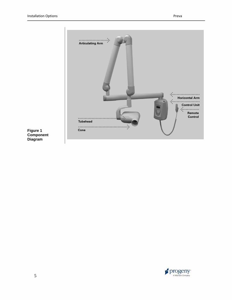
The Preva Dental X-Ray System is a state-of-the-art, high-frequency intra-oral x-ray machine. The Preva consists of five components, as shown in Figure 1 Component Diagram: the Control Unit, the Tubehead, the Articulating Arm, the Horizontal Arm, the Cone, and the Remote Control option.
Control Unit The Control Unit provides for the input power connection and control of the Tubehead and Operator Panel. It provides automatic line voltage compensation, kVp control, and exposure time control. The Control Unit consists of the mounting base and Operator Panel.
Tubehead The Tubehead contains the x-ray tube, high voltage circuit, and Cone. The Tubehead is shipped already assembled to the Articulating Arm.
Note: There is a small hole in the plastic handle covering the back of the Tubehead. Under no circumstances should this hole be blocked as it provides an air vent to allow the Tubehead oil to expand and contract as the unit is operated.
Articulating Arm
The Articulating Arm provides the articulation support for the Tubehead and the reach and coverage of the Tubehead to the patient. The Articulating Arm allows smooth movement for precise positioning and does not drift or vibrate when left in position.
Horizontal Arm The Horizontal Arm helps provide the necessary reach for the Preva. The Horizontal Arm pivots smoothly around a shaft inserted in the top of the Control Unit. The Horizontal Arm contains an access cover to connect the cable from the Horizontal Arm to the Control Unit. The Horizontal Arm is available in four lengths, providing reaches of 56, 66, 76 and 82 inches.
Cone The Cone establishes the distance from the x-ray tube to the patient’s skin. It provides positioning assistance and collimates the x-ray beam to within a defined circle at its end. The Preva is shipped with the standard 8 inch Cone attached to the Tubehead. A 12 inch Cone (30-A2033) can be ordered as an option.
Remote Control An optional component, the remote control switch is used to make exposures in addition to or replacing the use of the exposure button.
Mobile Unit
Installation and Service
An optional device, the mobile unit supports pre-programmed technique selections and x-ray acquisition. See Appendix A for the installation instructions for the mobile unit. The Preva Dental X-Ray System should only be installed and serviced by approved Progeny dealer personnel. Contact Progeny, A Midmark Company at (888) 924-3800 if you need assistance locating an approved dealer.

Installation Options Preva
4
CAUTIONS
When using lag screws as the method of attachment, it is imperative to consider the full scope of the task. Several factors must be considered for safe, permanent installations. Some of the key issues are:
• Lumber commonly used in construction projects can be different from location to location.
• The grade, age, position, and overall condition can vary greatly.
• The attachment stud may have additional, hidden loads.
• The location of the pilot hole with respect to the center of the stud will affect the load bearing ability.
• The size of the pilot hole required for the lag screw will be different based on the grade, age and condition of the lumber.
• Never over-tighten the lag screw as this will weaken the mechanical connection.
• Lumber with splits or cracks should not be used for attachment.
• Plywood, particle board, or similar construction materials, should not be used for attachment.
• Consider lumber dryness or moisture when attaching to exterior framing studs.
• Progeny mechanical designs will exert up to 850 pounds (386 kilograms) of loading on the supporting structure.
• Progeny provides fasteners for average installations. Based on specific installation conditions, it may be necessary to choose a alternate fastener or fastening methods.
• Seek the advice of a professional structural engineer to clarify any issues before the installation.
• Inspect the attachment method 30 days after the installation and, every 6 months thereafter.
Installation Options Preva
5
Figure 1 Component Diagram

Installation Options Preva
6
Reach and Coverage
The reach of the system is measured from the tip of the Cone with the arm fully extended and the Cone pointing back toward the pivot of the wall plate. This measurement method accommodates the normal positioning of the Tubehead to the patient. A patient can, therefore, be positioned without difficulty with the chair located within a radius outward from the pivot point to the dimensions shown in the diagrams.
Horizontal Arm Lengths
The Preva Horizontal Arm is available in three lengths. Each length gives the system a different reach. Catalog P7015 with a 30-A2074 Horizontal Arm has a reach of 56 inches. Catalog P7016 with a 30-A2073 Horizontal Arm has a reach of 66 inches. Catalog P7017 with a 30-A2071 Horizontal Arm has a reach of 76 inches. The diagrams show Catalog P7017 with a 76-inch reach. For Catalog P7016 with a 66 inch reach, reduce the dimensions by 10 inches. For Catalog P7015, reduce the dimensions by 20 inches.
Optional 12 Inch Cone
The 76-inch reach for Catalog P7017 assumes the use of the 8 inch Cone that is supplied with the system. If the optional 12 inch Cone (30-A2033) is used, the reach is reduced by 4 inches.
Figure 2 Reach and Coverage Diagram

Installation Options Preva
7
Figure 3 Cabinet Mounting Dimensions
82" reach not recommended for cabinet mount

Installation Options Preva
8
Figure 4 Retracted Wall Mount
Figure 5 Extended Position Wall or Cabinet Mount
note 1: 7015 24 5/8" ( 62.5cm) 7016 34 5/8" (88cm) 7017 44 5/8" (114cm) 7018 50 5/8 (128.5cm)
note 2: 7015 52 1/2" (133 cm) 7016 62 1/2" (159 cm) 7017 72 1/2" (184 cm) 7018 78 1/2 (199 cm) With 12" (30cm) cone
note 3: 7015 56 1/2" ( 143.5 cm) 7016 66 1/2" (169 cm) 7017 76 1/2" (194.5 cm) 7018 82 1/2" (209.5 cm) With 12" (30cm) cone
note 3: 7015 70 3/8" (178.5cm) 7016 80 3/8" (204 cm) 7017 90 3/8" (229.5 cm) 7018 96 3/8 (244.5 cm)
Installation Options Preva
9
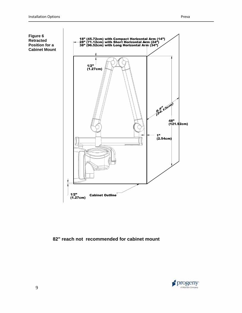
Figure 6 Retracted Position for a Cabinet Mount
82" reach not recommended for cabinet mount

Installation Options Preva
10
Figure 7 Mobile Unit Extended
Environmental Factors

Installation Options Preva
11
Use The Preva Dental X-Ray System is intended for indoor use for normal dental applications at temperatures in the range +50 F/+95 F (+10 / + 35 C) and at a maximum altitude of 12,000 feet. Humidity should not cause condensation to form on the unit.
Storage Storage temperature should not exceed the range -31 F / + 150 F (-35 C / + 66 C).
Support Requirements
The Preva Dental X-Ray System is designed to mount on a single wood 2x4-inch drywall stud or equivalent wall support. It can also be mounted on concrete or other similar wall construction. Mounting to a plywood or particle board wall is not acceptable. Verifying the wall support capability and the selection of the proper mounting hardware is the responsibility of the installer. Please note that a two-stud wall plate assembly (30-A2042) is available as an option to mount on two wooden studs. Assembly (30-A2043) is available as a metal stud mounting kit. The wall support and mounting hardware for the Preva must withstand a 100 lb. (45.36 kg) shear load and a 400 lb. (182 kg) withdrawal force at each of the mounting bolts. The wall fabrication and attachments to the building structure must be capable of withstanding a load moment of 850 ft. lbs. (118 kg.m.).
Electrical Requirements
Main Power Supply
The Preva Dental X-Ray System requires a three-wire electrician-supplied power supply. Two power lines, Line (LINE) and Neutral (NEUT), and a Ground (GND) are required. It is recommended that the unit be installed with a dedicated electrical line connected to a breaker with a minimum 15 amp rating. The wiring must provide for a permanently grounded power line configuration.
Line Cord Use The installer must determine the suitability of installing the Preva with a line cord. If a line cord is used, the installer must ensure that the unit is properly grounded and has the required line rating.
Line Voltage Nominal 110 - 230 VAC +/- 10%

Installation Options Preva
12
Fuse Rating 5A 250V UL Recognized
Max Line Resistance
Nominal Voltage120 - 230 VAC
Line Resistance 0.4 ohm
Compliance with Applicable Standards
Radiation Protection
The certified components of the Preva Dental X-Ray System comply with Radiation Performance Standards 21 CFR, Subchapter J, at the time of manufacture. The certified components of the Preva Dental X-Ray System comply with IEC 60601-1-3 Radiation protection/x-ray equipment.
UL 2601-1 File Number: E181750
Classified by Underwriters Laboratories Inc. with respect to electrical shock, fire and mechanical hazards only in accordance with UL 2601-1, and CAN/CSA C22.2 NO, 601.1-M90, and to the following particular standards, IEC60601-2-7, IEC60601-2-28.
EMI/EMC IEC60601-1-2
Certified Components
System Component Tubehead Control Unit Cone 8 in. Cone 12 in. Cone 8 in. Rectangular Cone 12 in Rectangular Cone 59mm Cone 60 mm
Reference Number30-A1027 30-A0010 30-A2016 30-A2033 30-A2041 30-A2112 30-A2107 30-A2101

Installation Options Preva
13
EC Declaration of Conformity
Name and Description of Product
Progeny Preva
Catalog Model Catalog Model
P7018, 82 inch reach 30-A0010, Control 30-A2164, Extension Arm, Extra Long P7017, 76-inch reach 30-A0010, Control 30-A2071, Extension Arm, Long
Catalog Model
P7016, 66-inch reach 30-A0010, Control 30-A2073, Extension Arm, Short
Catalog Model
P7015, 56-inch reach 30-A0010, Control 30-A2074, Extension Arm, Compact
Catalog Model
P7017-MG, Mobile 30-A0010, Control
Class IIb
Reference Numbers to which Conformity is Declared
The following regulatory documents apply: UL 2601-1 IEC 60601-1-2 IEC 60601-1-3 IEC 60601-2-7 IEC 60601-2-28 IEC 60601-2-32 Medical Device Directive ISO 13485 FDA 510K File Number K043092
Declaration Midmark Corporation declares that the products described herein meet all the applicable Essential Requirements of the EC Medical Device Directive 93/42/EEC in Annex I. For Class IIb products described herein, the product is manufactured, inspected, tested and released in accordance with the approved quality assurance system established in accordance with ISO 13485 and Annex II of the EC Medical Device Directive under the Supervision of the SGS United Kingdom Ltd. a Notified Body.
Contact Technical Support Progeny, Inc. [email protected]

Installation Options Preva
14
Authorized Representatives
North America Midmark Corporation 675 Heathrow Dr. Lincolnshire, IL 60069 Phone: 888-924-3800 Fax: 847-415-9801
Europe CE Partner 4U Esdoornlaah 13 3951DB Maarn The Netherlands Phone: +31.343.442.524 Fax: +31.343.442.162
Safety
Radiation Safety Only qualified and authorized personnel may operate this equipment observing all laws and regulations concerning radiation protection. • The operator at all times must remain 6ft. (2m) from the focal spot and the
x-ray beam for operator protection. • Full use must be made of all radiation safety features on the equipment. • Full use must be made of all radiation protection devices, accessories and
procedures available to protect the patient and operator from x-ray radiation.
Electrical Safety • Only qualified and authorized service personnel should remove covers on the equipment.
• This equipment must only be used in rooms or areas that comply with all applicable laws and recommendations concerning electrical safety in rooms used for medical purposes, e.g., IEC, US National Electrical code, or VDE standards concerning provisions of an additional protective earth (ground) terminal for power supply connection.
• Before cleaning or disinfecting, this equipment must always be disconnected from the main electrical supply.
• The Preva Dental X-Ray System is ordinary type medical equipment without protection against ingress of liquids. To protect against short-circuit and corrosion, no water or any other liquid should be allowed to leak inside the equipment.
Explosion Safety
This equipment must not be used in the presence of flammable or potentially explosive gases or vapors, which could ignite, causing personal injury and/or damage to the equipment. If such disinfectants are used, the vapor must be allowed to disperse before using the equipment.
Explanation of Symbols on Technical Labels
Installation Options Preva
15
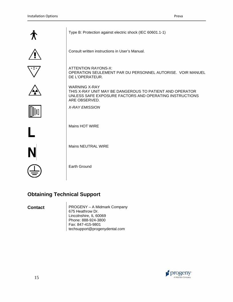
Type B: Protection against electric shock (IEC 60601.1-1)
Consult written instructions in User’s Manual.
ATTENTION RAYONS-X: OPERATION SEULEMENT PAR DU PERSONNEL AUTORISE. VOIR MANUEL DE L’OPERATEUR.
WARNING X-RAY THIS X-RAY UNIT MAY BE DANGEROUS TO PATIENT AND OPERATOR UNLESS SAFE EXPOSURE FACTORS AND OPERATING INSTRUCTIONS ARE OBSERVED.
X-RAY EMISSION
Mains HOT WIRE
Mains NEUTRAL WIRE
Earth Ground
Obtaining Technical Support
Contact PROGENY – A Midmark Company 675 Heathrow Dr. Lincolnshire, IL 60069 Phone: 888-924-3800 Fax: 847-415-9801 [email protected]
Installation Options Preva
16
Installation Options
Mounting Configurations
Mounting Template
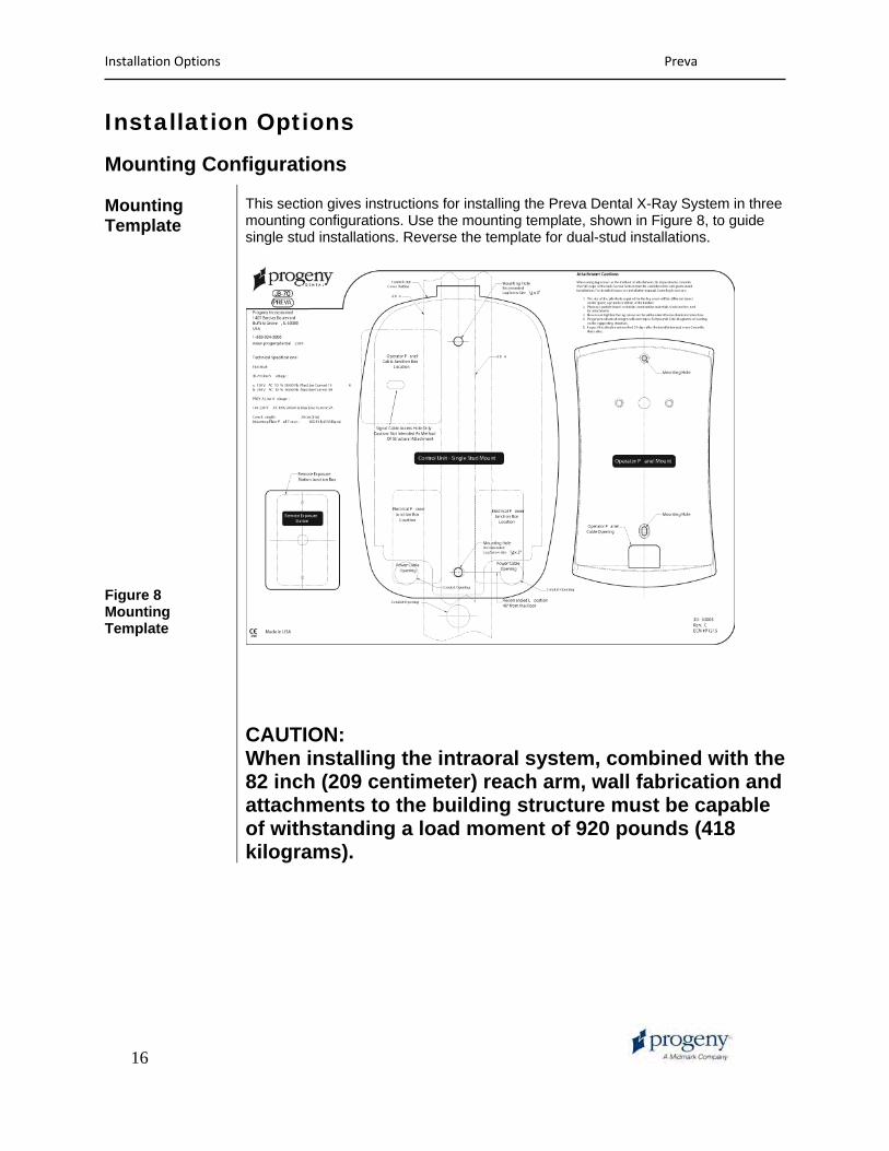
This section gives instructions for installing the Preva Dental X-Ray System in three mounting configurations. Use the mounting template, shown in Figure 8, to guide single stud installations. Reverse the template for dual-stud installations.
Figure 8 Mounting Template
CAUTION: When installing the intraoral system, combined with the 82 inch (209 centimeter) reach arm, wall fabrication and attachments to the building structure must be capable of withstanding a load moment of 920 pounds (418 kilograms).
Installation Options Preva
17
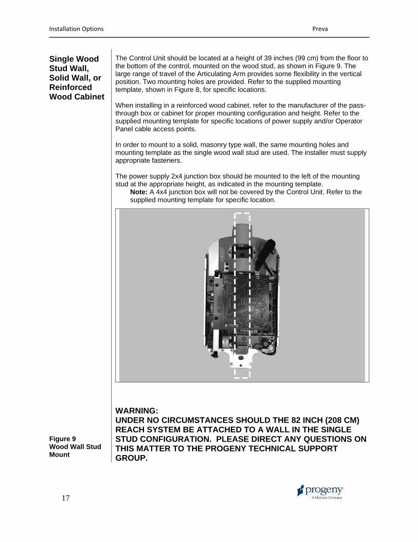
Single Wood Stud Wall, Solid Wall, or Reinforced Wood Cabinet
The Control Unit should be located at a height of 39 inches (99 cm) from the floor to the bottom of the control, mounted on the wood stud, as shown in Figure 9. The large range of travel of the Articulating Arm provides some flexibility in the vertical position. Two mounting holes are provided. Refer to the supplied mounting template, shown in Figure 8, for specific locations. When installing in a reinforced wood cabinet, refer to the manufacturer of the pass-through box or cabinet for proper mounting configuration and height. Refer to the supplied mounting template for specific locations of power supply and/or Operator Panel cable access points. In order to mount to a solid, masonry type wall, the same mounting holes and mounting template as the single wood wall stud are used. The installer must supply appropriate fasteners. The power supply 2x4 junction box should be mounted to the left of the mounting stud at the appropriate height, as indicated in the mounting template.
Note: A 4x4 junction box will not be covered by the Control Unit. Refer to the supplied mounting template for specific location.
Figure 9 Wood Wall Stud Mount
WARNING: UNDER NO CIRCUMSTANCES SHOULD THE 82 INCH (208 CM) REACH SYSTEM BE ATTACHED TO A WALL IN THE SINGLE STUD CONFIGURATION. PLEASE DIRECT ANY QUESTIONS ON THIS MATTER TO THE PROGENY TECHNICAL SUPPORT GROUP.

Installation Options Preva
18
Dual Wood Stud Wall
When installing the Preva Dental X-Ray System on two 16-inch centered wood studs, the Control Unit mounts to a wall plate (Two Stud Mounting Kit 30-A2042, purchased as an option), which mounts to the wood studs, as shown in Figure 10. Fasteners are provided with the wall plate. In mounting configurations using the dual stud wall plate, there are several holes available for incoming line power. This is to provide for various locations of existing power boxes when installing as a replacement unit. Refer to the reverse side of the mounting template, Figure 8, for hole locations.
Figure 10 Dual Wood Stud Mount

Installation Options Preva
19
Metal Stud Wall
When installing the Preva Dental X-Ray System on a metal stud wall, the Control Unit mounts to a wall plate (Two Stud Mounting Kit 30-A2042, purchased as an option) and uses an additional support plate (Metal Stud Support Plate Kit 30-A2043, purchased as an option) positioned on the back end of the wall. See Figure 11. Fasteners are provided with the wall plate and support plate. The wall fabrication and attachments to the building structure must be capable of withstanding a load moment of 850 ft. lbs. (118 kg.m.). If the wall on which the Preva is to be installed does not meet this requirement, it must be reinforced. In mounting configurations using the dual stud wall plate, there are several holes available for incoming line power. This is to provide for various locations of existing power boxes when installing as a replacement unit. Refer to the mounting template in Figure 8 for hole locations.
Figure 11 Metal Stud Mount
Installation Options Preva
20
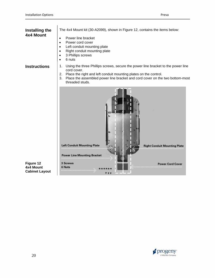
Installing the 4x4 Mount
The 4x4 Mount kit (30-A2099), shown in Figure 12, contains the items below: • Power line bracket • Power cord cover • Left conduit mounting plate • Right conduit mounting plate • 3 Phillips screws • 6 nuts
Instructions 1. Using the three Phillips screws, secure the power line bracket to the power line cord cover.
2. Place the right and left conduit mounting plates on the control. 3. Place the assembled power line bracket and cord cover on the two bottom-most
threaded studs.
Figure 12 4x4 Mount Cabinet Layout

Installation Options Preva
21
Operator Panel Locations
The Operator Panel for the Preva Dental X-Ray System can be installed on the Control Unit or mounted remotely on a wall.
On Control Unit The Operator Panel snaps on to the front of the Control Unit. Installation of the Operator Panel on the Control Unit may require the purchase and use of the coil-cord hand switch option, 30-A2040.
Remote Operator Panel
The Operator Panel is mounted on the wall remote from the Control Unit. If the Operator Panel is mounted separate from the Control Unit, a supplied cable must be run from the Control Panel to the Operator Panel. Where local codes require, a separate 2x4 junction box should be mounted to the left of the mounting stud above the power supply box. Refer to the supplied mounting template for specific location.
22
Installation Procedures
Preparing to Install the Preva
Check Pre-installation Requirements
Prior to beginning the installation, be sure that all pre-installation requirements have been completed. This includes confirming that the wall support requirements are adequate for mounting the unit and that the electrical power requirements and wire locations are proper.
Note: Progeny recommends that the Preva Dental X-Ray System be connected to dedicated wiring and permanently grounded. The installer must determine the suitability of using a line cord at the time of installation, ensuring proper grounding technique.
Gather Tools Items needed for all types of mounts: • Stud finder • Bubble level (torpedo level) • Masking or other tape for placing the mounting template on the wall • Awl • Drill driver and drill bits appropriate to type of wall mounting • Metric Allen wrench set • English (inch) Allen wrench set • Screwdrivers (flat-blade and Phillips) • Torque wrench 0-40 ft-lbs. or equivalent • Sockets and ratchet driver appropriate to type of wall mounting • Fluke model 73 DVM equivalent or better • Small test clips (such as Pomona Electronics Minigrabber Test Clip Model
6248 or Radio Shack Mini-Hook Adapters catalog # 270-334) Items needed only for the metal stud wall mount: • 1-inch hole saw • Dry wall saw • ¼-inch diameter 12-inch long drill bit • Two 4x4 wood studs • Drywall screws
Installation Time The Preva Dental X-Ray System has been designed to be installed by one person in less than one hour, assuming that all pre-installation requirements have been met.
Open the Shipping Carton
The Preva Dental X-Ray System is shipped in a convenient two-level carton, as shown in Figure 13. The first level contains the items needed for the first part of the installation, including the Control Unit, Operator Panel, Horizontal Arm, mounting template, documentation, cables, and bags containing the mounting hardware, brake assembly plastic covers, and additional hardware. The Articulating Arm and Tubehead Assembly is in the second level of the shipping carton, where it can remain until it is installed.

Installation Procedures Preva
23
Figure 13 Two-level Carton
Packing List Part Number Description Quantity30-A1010 Articulating Arm and Tubehead Assembly 1 30-A1025 Control Unit Assembly 1 30-A2076 Operator Panel 1 30-P0029 Operator Panel Mounting Cradle 1 30-A2046 Preva Mounting Hardware Kit 1 30-A2156 Preva Plastic Covers / Brake Kit 1 E1-13002 Line Cord, 16/3 6' Wide 1 E1-13003 8 Cond. RJ45 to RJ45 25 ft. 1 E1-13004 8 Cond. RJ45 to RJ45 6 in. 1 30-A-2086 Preva Documentation Kit 1
Note: Shipment Contains One of the Following Extension Arms Per Order30-A2071 Extension Arm, Long 1 30-A2073 Extension Arm, Short 1 30-A2074 Extension Arm, Compact 1 30-A2164 Extension Arm, Extra Long 1
Options
E1-13034 8 Cond. RJ45 to RJ45 50 ft. 30-08101 Doorbell Switch 30-A2044 Lighted Doorbell Switch 30-A2041 8 inch Rectangular Cone 22-11466 8mm Adjustment Wrench 22-11467 Fluorescent Screen 30-A2042 16-inch Mounting Plate
00-02-0488 FDA Form 2579 30-A2100 Service Kit 30-A2099 4x4 Mount Kit 30-A2152 Series Exposure Switch Kit
Installing the Control Unit on a Single Wood Stud Wall

Installation Procedures Preva
24
Mark and Drill Control Unit Mounting Holes
WARNING: UNDER NO CIRCUMSTANCES SHOULD THE 82 INCH (208 CM) REACH SYSTEM BE ATTACHED TO A WALL IN THE SINGLE STUD CONFIGURATION. PLEASE DIRECT ANY QUESTIONS ON THIS MATTER TO THE PROGENY TECHNICAL SUPPORT GROUP. The mounting template is a guide for locating where to drill the holes used to mount the Control Unit to the wall. Carefully placing the mounting template on the wall will help ensure correct installation of the Control Unit. 1. Using a stud finder, locate the center of the stud on which the Control Unit
will be mounted. 2. Place the mounting template on the wall with the lower mounting hole 40
inches above the floor. 3. Place a level parallel to the vertical lines on the mounting template and adjust
the mounting template until it is plumb. 4. Tape the mounting template to the wall. 5. Using an awl or other sharp object, punch through the mounting template to
mark the location of the upper and lower mounting holes.
CAUTION! It is very important that both mounting holes are in the center of the wood stud.
6. Drill upper and lower 5/32” pilot holes (for common pine studs) at marked locations.
7. Remove the mounting template from the wall and save for future use.
Remove Control Unit Front Cover
1. Open the shipping carton and locate the Control Unit in the first level of the carton.
2. Remove the Phillips screw from the front cover of the Control Unit. 3. Carefully remove the front cover. 4. Place the front cover and the screw in a safe location for later reassembly.
Mount and Level the Control Unit
1. Select the 3/8 inch 3–inch long lag screws and washers. Note: For concrete walls, the installer must supply the appropriate mounting bolts.
2. Put the upper lag screw and washer through the upper mounting hole of the Control Unit.
3. Place the Control Unit on the wall and loosely tighten the upper mounting bolt.
4. Put the lower lag screw and washer through the lower mounting hole of the Control Unit and loosely tighten. Be sure that the power wire extends through the opening at the bottom of the Control Unit.
5. Place a level on the Control Unit bearing parallel to the wall, as shown in Figure 14. Level the Control Unit.
6. Tighten the upper and lower lag screws to 14 to 18 ft-lbs. 7. Predrill a hole for a # 12 wood screw below the lower lag screw, as shown in
Figure 14 A. Install and tighten the wood screw to prevent the unit from shifting.
CAUTION! Do not over tighten the lag screws. Over tightening the

Installation Procedures Preva
25
lag screws will damage the wooden stud and reduce the holding force.
Figure 14 Leveling the Control Unit
Figure 14 A
For #12 Screw

Installation Procedures Preva
26
Installing the Control Unit on a Dual Wood Stud Wall
Mark and Drill Wall Plate Mounting Holes
The mounting template is a guide for locating where to drill the holes used to mount the wall plate to the wall. Carefully placing the mounting template for two stud mount installations on the wall will help ensure correct installation of the mounting plate and, hence, the Control Unit. 1. Using a stud finder, locate the center of the studs on which the wall plate will
be mounted. 2. Place the mounting template for the two stud mount on the wall with the
lower mounting holes 40 inches above the floor. 3. Place a level parallel to the vertical lines on the mounting template and adjust
the mounting template until it is plumb. 4. Tape the mounting template to the wall. 5. Using an awl or other sharp object, punch through the mounting template to
mark the location of the mounting holes. 6. Drill 5/32” pilot holes (for common pine studs) at marked locations. 7. Remove the mounting template from the wall and save for future use.
Install the Wall Plate (30-A2042)
In the dual wood wall stud installation, the Control Unit is bolted to a wall plate that has been installed on two wood studs. The wall plate, shown in Figure 15, is shipped separately from the Preva. 1. Select the 3/8 inch 3-inch long lag screws and washers. 2. Put the lag screws and washers through the mounting holes on the wall plate
and loosely tighten. Be sure that the power wire extends through the opening in the wall plate.
3. Level the wall plate. 4. Tighten the lag screws to 14 to 18 ft-lbs.
CAUTION! Do not over tighten the lag screws. Over tightening the lag screws will damage the wooden stud and reduce the holding force.

Installation Procedures Preva
27
Figure 15 Mounting Plate for Dual Stud Wall Mounts
Remove Control Unit Front Cover
1. Open the shipping carton and locate the Control Unit in the first level of the carton.
2. Remove the Phillips screw from the front cover of the Control Unit. 3. Carefully remove the front cover. 4. Place the front cover and the screw in a safe location for later reassembly.
Mount the Control Unit
1. Select the 5/16-inch ¾-inch long socket cap screws and washers. 2. Put the upper screw and washer through the upper mounting hole of the
Control Unit. 3. Place the Control Unit on the wall and loosely tighten the upper screw. 4. Put the lower screw and washer through the lower mounting hole of the
Control Unit and loosely tighten. Be sure that the power wire extends through the opening at the bottom of the Control Unit.
5. Place a level on the Control Unit bearing parallel to the wall. Level the Control Unit.
6. Tighten the upper and lower screws. 7. After the Preva is installed, slide covers on the wall plate and screw on.

Installation Procedures Preva
28
Installing the Control Unit on a Metal Stud Wall
Mark and Drill Wall Plate and Support Plate Mounting Holes
The mounting template is a guide for locating where to drill the holes used to mount the wall plate and support plate to the wall. Carefully placing the mounting template on the wall will help ensure correct installation of these plates and, hence, of the Control Unit. 1. Using a stud finder, locate the center of the stud on which the Control Unit
will be mounted. 2. Place the mounting template for the dual stud mount on the wall with the
lower mounting holes 40 inches above the floor. 3. Place a level parallel to the vertical lines on the mounting template and adjust
the mounting template until it is plumb. 4. Tape the mounting template to the wall. 5. Using an awl or other sharp object, punch through the mounting template to
mark the location of the mounting holes. 6. Drill ¼-inch pilot holes at marked locations. 7. Drill 1-inch clearance holes. 8. Remove the mounting template from the wall and save for future use.
Reinforce Metal Stud Wall
Filler material is added to the wall to prevent the metal stud wall from being crushed during installation. 1. Cut an access hole 6 inches by 10 inches in size between the clearance
holes. 2. Insert two 4x4 wooden studs in the access hole. Attach the studs to the rear
drywall surface with drywall screws.
CAUTION! The sheet metal stud wall must be secure to hold a load of 850 ft. lbs. (118 kg.m.).
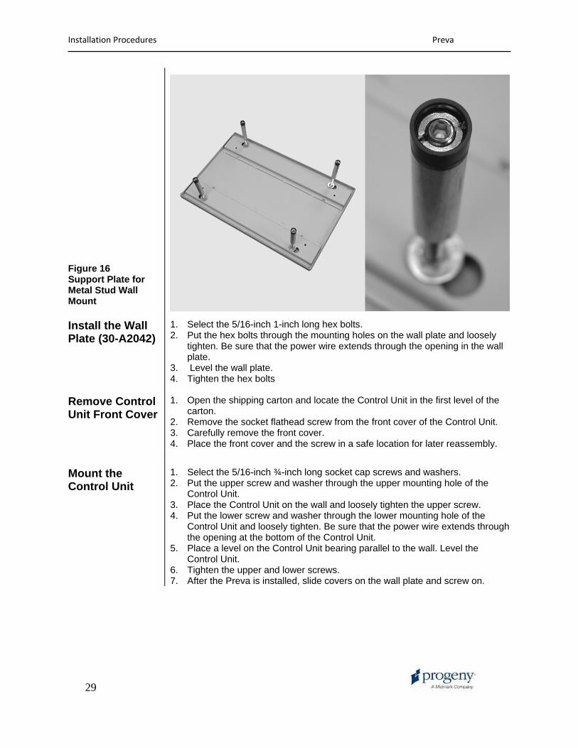
Assembling and Mounting the Support Plate (30-A2043)
In the metal wall stud installation, the Control Unit is bolted to a wall plate (Figure 15) that has been installed to the support plate shown in Figure 16. The wall and support plates are shipped separately from the Preva. 1. Put the small, then the larger washers and nut on each of the four carriage
bolts. 2. Insert the carriage bolts into the support plate holes. 3. Screw the threaded standoffs onto the carriage bolts with the slotted ends
away from the back plate. 4. Place the plastic sleeve bearings in the slotted ends of the carriage bolts. 5. Using a 5/32 Allen key, insert a set screw into each threaded standoff. Screw
the set screw until just below the slot in the threaded standoff, but do not tighten.
6. Using two sheet metal screws, mount and level the support plate through the pilot holes on the back side of the wall. Tighten the sheet metal screws with the screw driver.
7. On the front side of the wall, using a straight-blade screw driver, adjust the threaded standoffs until the plastic part is flush with the drywall.
8. Tighten the set screws in the threaded standoffs to lock them in place.
Installation Procedures Preva
29
Figure 16 Support Plate for Metal Stud Wall Mount
Install the Wall Plate (30-A2042)
1. Select the 5/16-inch 1-inch long hex bolts. 2. Put the hex bolts through the mounting holes on the wall plate and loosely
tighten. Be sure that the power wire extends through the opening in the wall plate.
3. Level the wall plate. 4. Tighten the hex bolts
Remove Control Unit Front Cover
1. Open the shipping carton and locate the Control Unit in the first level of the carton.
2. Remove the socket flathead screw from the front cover of the Control Unit. 3. Carefully remove the front cover. 4. Place the front cover and the screw in a safe location for later reassembly.
Mount the Control Unit
1. Select the 5/16-inch ¾-inch long socket cap screws and washers. 2. Put the upper screw and washer through the upper mounting hole of the
Control Unit. 3. Place the Control Unit on the wall and loosely tighten the upper screw. 4. Put the lower screw and washer through the lower mounting hole of the
Control Unit and loosely tighten. Be sure that the power wire extends through the opening at the bottom of the Control Unit.
5. Place a level on the Control Unit bearing parallel to the wall. Level the Control Unit.
6. Tighten the upper and lower screws. 7. After the Preva is installed, slide covers on the wall plate and screw on.
Installation Procedures Preva
30
Installing the Horizontal Arm and Brake Assembly
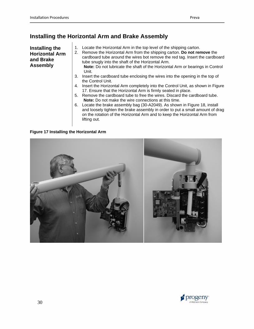
Installing the Horizontal Arm and Brake Assembly
1. Locate the Horizontal Arm in the top level of the shipping carton. 2. Remove the Horizontal Arm from the shipping carton. Do not remove the
cardboard tube around the wires bot remove the red tag. Insert the cardboard tube snugly into the shaft of the Horizontal Arm.
Note: Do not lubricate the shaft of the Horizontal Arm or bearings in Control Unit. 3. Insert the cardboard tube enclosing the wires into the opening in the top of
the Control Unit. 4. Insert the Horizontal Arm completely into the Control Unit, as shown in Figure
17. Ensure that the Horizontal Arm is firmly seated in place. 5. Remove the cardboard tube to free the wires. Discard the cardboard tube.
Note: Do not make the wire connections at this time. 6. Locate the brake assembly bag (30-A2049). As shown in Figure 18, install
and loosely tighten the brake assembly in order to put a small amount of drag on the rotation of the Horizontal Arm and to keep the Horizontal Arm from lifting out.
Figure 17 Installing the Horizontal Arm

Installation Procedures Preva
31
Figure 18 Installing the Brake Assembly
Installation Procedures Preva
32
Installing the Articulating Arm and Tubehead Assembly
Install the Articulating Arm and Tubehead Assembly
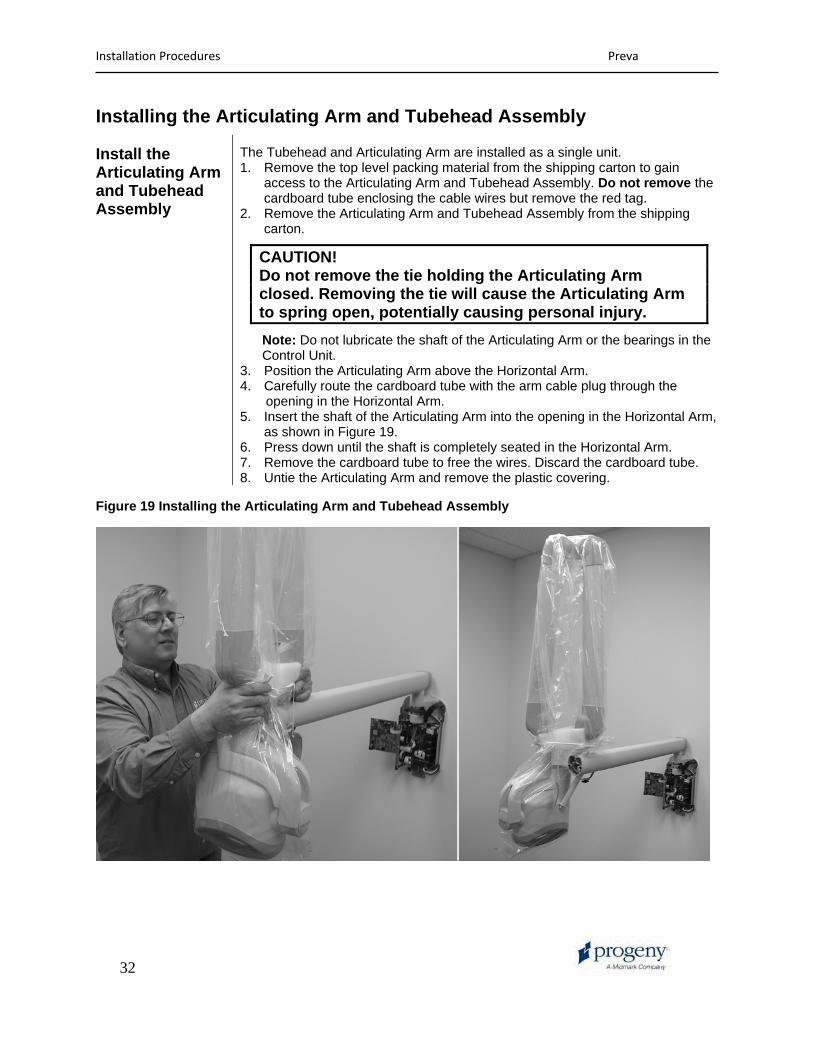
The Tubehead and Articulating Arm are installed as a single unit. 1. Remove the top level packing material from the shipping carton to gain
access to the Articulating Arm and Tubehead Assembly. Do not remove the cardboard tube enclosing the cable wires but remove the red tag.
2. Remove the Articulating Arm and Tubehead Assembly from the shipping carton.
CAUTION! Do not remove the tie holding the Articulating Arm closed. Removing the tie will cause the Articulating Arm to spring open, potentially causing personal injury.
Note: Do not lubricate the shaft of the Articulating Arm or the bearings in the Control Unit. 3. Position the Articulating Arm above the Horizontal Arm. 4. Carefully route the cardboard tube with the arm cable plug through the opening in the Horizontal Arm. 5. Insert the shaft of the Articulating Arm into the opening in the Horizontal Arm,
as shown in Figure 19. 6. Press down until the shaft is completely seated in the Horizontal Arm. 7. Remove the cardboard tube to free the wires. Discard the cardboard tube. 8. Untie the Articulating Arm and remove the plastic covering.
Figure 19 Installing the Articulating Arm and Tubehead Assembly

Installation Procedures Preva
33
Install the Articulating Arm Brake Assembly
1. Locate the Articulating Arm brake assembly (30-A2068). 2. Insert the M6 x 25 mm long set screw, as shown in Figure 20. Using a 3 mm
Allen wrench, tighten the screw fully than back off ¼ and secure with the hex nut.
3. Using a 3 mm Allen wrench, install the Articulating Arm brake. Tighten screws until the Articulating Arm brake comes into contact with the shaft of the Articulating Arm. If additional friction is required to prevent drifting, turn the two screws evenly ~¼ turn at a time until drift stops, as shown in Figure 21.
Figure 20 Installing the Hex Nut and Set Screw
Figure 21 Adjusting the Articulating Arm Brake Assembly
Installation Procedures Preva
34
Connecting the Cables
Connecting the Articulating and Horizontal Arm Cables
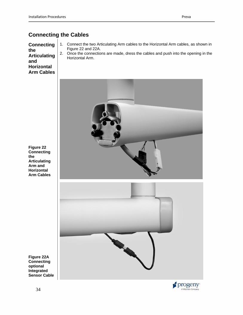
1. Connect the two Articulating Arm cables to the Horizontal Arm cables, as shown in Figure 22 and 22A.
2. Once the connections are made, dress the cables and push into the opening in the Horizontal Arm.
Figure 22 Connecting the Articulating Arm and Horizontal Arm Cables
Figure 22A Connecting optional Integrated Sensor Cable
Installation Procedures Preva
35
Connecting the Horizontal Arm Cables to the Power Supply Board
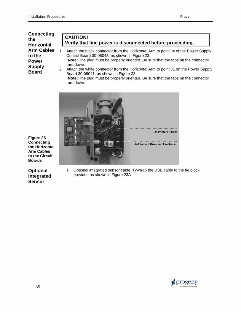
CAUTION! Verify that line power is disconnected before proceeding.
1. Attach the black connector from the Horizontal Arm to point J4 of the Power Supply Control Board 30-08043, as shown in Figure 23. Note: The plug must be properly oriented. Be sure that the tabs on the connector are down.
2. Attach the white connector from the Horizontal Arm to point J1 on the Power Supply Board 30-08041, as shown in Figure 23. Note: The plug must be properly oriented. Be sure that the tabs on the connector are down.
Figure 23 Connecting the Horizontal Arm Cables to the Circuit Boards
Optional Integrated Sensor
1. Optional integrated sensor cable. Ty-wrap the USB cable to the tie block provided as shown in Figure 23A

Installation Procedures Preva
36
Figure 23A Tying optional sensor cable out of harms way
Attach provided tie block here, loop and tie the cable to the tie block.

Installation Procedures Preva
37
Connecting Line Power
1. Using a 3 mm Allen wrench, remove the power line terminal strip cover at the base of the Power Supply Control Board to gain access to the power line terminal strip, as shown in Figure 24.
2. Attach a flanged spade and connect the hot (black) wire of the power line to the connection identified as LINE on the power strip.
3. Attach a flanged spade and connect the neutral (white) wire of the line to the connection identified as NEUT on the power strip.
4. Attach a flanged spade and connect the ground (green) wire of the line to the connection identified as GND on the power strip.
5. Leave the power line terminal strip cover off until the following electrical verification procedure is complete.
Figure 24 Power Line Terminal Strip Cover
Connecting the Operator Panel with the 25 ft. Cable
During initial powerup and verification, the Operator Panel is required. Connect the Operator Panel with the 25 ft. interconnect cable. Later you will connect the Operator Panel in its final position for use. 1. Identify the Operator Panel and the 25 ft. interconnect cable. 2. Plug the cable into the left socket at the base of the Operator Panel. 3. Plug the other end of the cable into connector J1 on the Power Supply Control
Board 30-08043, as shown in Figure 24.
Installation Procedures Preva
38
Electrical Verification
Calibration Calibration of the Preva Dental X-Ray System is preset at the factory and is not required during initial installation. Service replacement of the Power Supply Control Board 30-08043 or the Tubehead will require calibration. See the Calibration section of this manual.
Verifying Input Voltage and Turning On the System
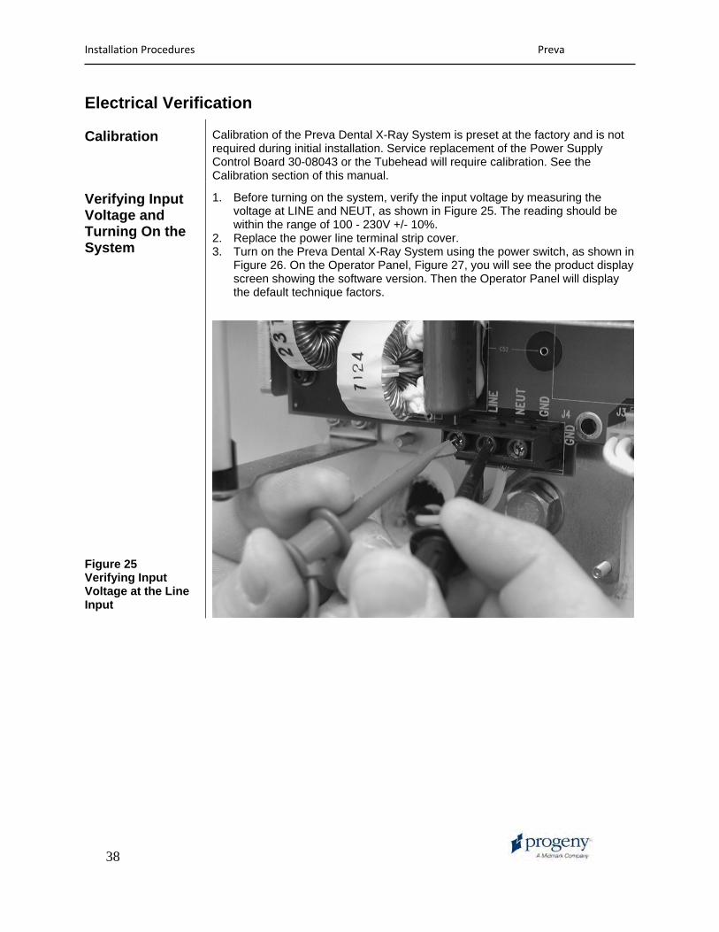
1. Before turning on the system, verify the input voltage by measuring the voltage at LINE and NEUT, as shown in Figure 25. The reading should be within the range of 100 - 230V +/- 10%.
2. Replace the power line terminal strip cover. 3. Turn on the Preva Dental X-Ray System using the power switch, as shown in
Figure 26. On the Operator Panel, Figure 27, you will see the product display screen showing the software version. Then the Operator Panel will display the default technique factors.
Figure 25 Verifying Input Voltage at the Line Input