preventative maintenance checklists
DESCRIPTION
Preventative Maintenance ChecklistsTRANSCRIPT

Preventive Maintenance
Check List
Version 1.2
March 1995

PREVENTIVE MAINTENANCE FOR THE
Highway Engineering SYSTEM March, 95Cassiar Connector File: E4C0001M.DOCPreventive Maintenance Check List Page: 1
This is file: E4C0001M.DOC
Procedure for printing preventive maintenance check lists:
FILEFIND FILEADVANCED SEARCH
- select the sub-directory where the check lists reside- ADD this directory to the Search in: box - remove any other directories from this box.- enter *.DOC in the File name: box- click OK
OK- select the files to be printed by highlighting - use the shift or control keys formultiple selections.
COMMANDSPRINTOK
(see page 2)

PREVENTIVE MAINTENANCE FOR THE
Highway Engineering SYSTEM March, 95Cassiar Connector File: E4C0001M.DOCPreventive Maintenance Check List Page: 2
Procedure for creating preventive maintenance check lists from the maintenancestandards:
The HEADER and FOOTER of this file are used when generating a checklist from theCassiar Standards Manual.
The following table row is the second row for use when generating a checklist:Item: �
OPEN A NEW OR EXISTING CHECKLIST FILE
OPEN THIS FILE E4C0001M.DOC
OPEN THE STANDARD FILE CONTAINING THE CHECKLIST
SELECT THE CHECKLIST IN THE STANDARD AND COPY IT TO THE NEW OREXISTING CHECKLIST FILE.
SELECT THE PORTION(S) OF THE COPIED CHECKLIST WHICH REQUIRE ACHECK COLUMN AND PRESS ALT + X (MACRO)TO ADD A COLUMN TO THETABLE.
SELECT THE ADDED COLUMN AND PRESS ALT+W (MACRO) TO FORMAT THECHECK COLUMN
DELETE THE “TABLE 999.09” HEADING ROW FROM THE CHECKLIST TABLE
COPY THE “ITEM” ROW FROM THIS FILE TO THE SECOND LINE OF THECHECKLIST TABLE.
ADD CHECK BOXES WHERE APPROPRIATE USING ALT+Z
PAGE THE CHECKLIST BY INSERTING PAGE BREAKS AND ADDING BORDERSWHERE REQUIRED. USE ALT+P IF YOU ARE BRAVE.

MONTHLY PREVENTIVE MAINTENANCE FOR THEHONEYWELL DDC CONTROL SYSTEM
Highway Engineering HONEYWELL CONTROL SYSTEM March, 95Cassiar Connector File: E4C0201M.DOCPreventive Maintenance Check List Page -1
Item: �
1 General:.1 The maintenance listed in this table shall be done once a month..2 Notify tunnel operator 48 hours prior to maintenance..3 This maintenance shall be done during a week day when expert
help and parts may be available..4 PM maintenance shall not be performed during rush hours or
emergencies..5 Check with the tunnel operator and facility log book for problems
relating to this equipment.
2 Cautions:.1 Do not use a vacuum cleaner in the immediate vicinity of any
computer printed circuit boards. The high velocity air movementmay create a high static electrical charge which may damage theequipment.
3 General Lock-out:.1 Refer to the Lock-out Section 103 of the Cassiar Tunnel Electrical
Maintenance Standards manual.
4 Equipment:.1 Honeywell ( DDC ) panels 1, 2, 3, 4, and 5 - located in
substation..2 Fail Safe Panel - located in substation adjacent to DDC panels..3 Fire-fighters’ Control Panel - located in operators’ control room..4 Emergency Backup Panel - located in operators’ control room..5 PC Computer, Monitor and Printer - located in operators’ control
room..6 Tunnel Fan MCC - DDC relay control sections - located in 3
substation MCC cabinets adjacent to tunnel fan MCCs.

MONTHLY PREVENTIVE MAINTENANCE FOR THEHONEYWELL DDC CONTROL SYSTEM
Highway Engineering HONEYWELL CONTROL SYSTEM March, 95Cassiar Connector File: E4C0201M.DOCPreventive Maintenance Check List Page -2
5 Honeywell ( DDC ) panels 1, 2, 3, 4, and 5:.1 Check the six LEDs located on the bottom of the processor board:
.1 The three on the right column of should be “off”.
.2 The three on the left column should be:.1 - DIAG “on”.2 - TRANS “blinks constantly”.3 - REC “on”
left column leds right column ledspanel DIAG TRANS REC off off off
12345
.3 If these do not flash as noted above check the transformerand fuse then notify Honeywell.
�
.4 Visually inspect and clean the panels. �
.5 Close and lock the panel doors. �
6 Fail Safe Panel:.1 Caution: Do not operate the toggle switch. This switch should be
left in the centre position. This is a very “sensitive” switch to set..2 Visually inspect and clean the panel. �
.3 Close and lock the panel door. �
7 Tunnel Fan T/D relays control sections:.1 Visually inspect and clean the equipment. �
.2 Caution: Do not adjust the delay time settings on these relays asthey sequence the starting to prevent overload conditions on start-up.
�

MONTHLY PREVENTIVE MAINTENANCE FOR THEHONEYWELL DDC CONTROL SYSTEM
Highway Engineering HONEYWELL CONTROL SYSTEM March, 95Cassiar Connector File: E4C0201M.DOCPreventive Maintenance Check List Page -3
8 Emergency Backup Panel:.1 Unlock and open panel door. This will disable all other control of
the tunnel fans, stop the fans and give control to this panel.�
.2 Visually inspect and clean the panel. �
.3 Check that the Tunnel Fans MCC starter switches are in the “auto”position and the indicator lamps show “off” green.
�
.4 Press the panel buttons to forward each fan pair. �
.5 Check and record the appropriate indicator lamps on theEmergency Backup Panel (EBP) Tunnel Fans MCCs and theHoneywell Computer Monitor (HCM).
.6 Press the panel buttons to stop each fan pair.
.7 Check and record the appropriate indicator lamps on theEmergency Backup Panel (EBP) Tunnel Fans MCCs and theHoneywell Computer Monitor (HCM).
.8 Press the panel buttons to reverse each fan pair.
.9 Check and record the appropriate indicator lamps on theEmergency Backup Panel (EBP) Tunnel Fans MCCs and theHoneywell Computer Monitor (HCM).
Forwardindications
Stopindications
Reverseindications
M E H M E H M E HC B C C B C C B C
Fan� C P M C P M C P MFF-S-8AFF-S-8BFF-S-7AFF-S-7BFF-S-6AFF-S-6BFF-S-5AFF-S-5BFF-S-4AFF-S-4BFF-S-3AFF-S-3BFF-S-2AFF-S-2BFF-S-1AFF-S-1B

MONTHLY PREVENTIVE MAINTENANCE FOR THEHONEYWELL DDC CONTROL SYSTEM
Highway Engineering HONEYWELL CONTROL SYSTEM March, 95Cassiar Connector File: E4C0201M.DOCPreventive Maintenance Check List Page -4
Forwardindications
Stopindications
Reverseindications
M E H M E H M E HC B C C B C C B C
Fan� C P M C P M C P MFF-N-8AFF-N-8BFF-N-7AFF-N-7BFF-N-6AFF-N-6BFF-N-5AFF-N-5BFF-N-4AFF-N-4BFF-N-3AFF-N-3BFF-N-2AFF-N-2BFF-N-1AFF-N-1B
.10 Close and lock panel door. This will stop any fans and returncontrol of the tunnel fans to the Honeywell.
�
.11 Return the key to the “red” box. �

MONTHLY PREVENTIVE MAINTENANCE FOR THEHONEYWELL DDC CONTROL SYSTEM
Highway Engineering HONEYWELL CONTROL SYSTEM March, 95Cassiar Connector File: E4C0201M.DOCPreventive Maintenance Check List Page -5
9 Fire-fighters’ Control Panel:.1 Visually inspect and clean the exterior of the panel. �
.2 Insert and turn the key to activate the panel. �
.3 The “General Fire” lamp should be “off” �
.4 The “Hydro Failure” lamp should be “off” �
.5 The “Controller Failure” lamp should be “off” �
.6 The “Normal” lamp should be “on” �
.7 The “Fire S.B. Tube” lamp should be “off” �
.8 The “Fire N.B. Tube” lamp should be “off” �
.9 Press “Lamp Test” button to test lamps - all lamps should light. �
.10 Ensure that the Emergency Backup Panel door is closed. �
.11 Press buttons to activate each selection in turn. Check and recordindication of each fan on the Firefighters’ Control Panel and theEmergency Backup Panel:
Lamps
Selection
EmergencyBackupPanel
Firefighters’ControlPanel
S.B. Tube - Fan ForwardS.B. Tube - Fan Stop
S.B. Tube - Fan ReverseN.B. Tube - Fan Forward
N.B. Tube - Fan StopN.B. Tube - Fan Reverse
.12 Turn “off” key and return to “red” box. �
.13 Press “Reset to Auto” button. �
.14 Visually check that Firefighters’ Control Panel has returned tonormal.
�
.15 Check that Honeywell alarms have been restored to normal. �
10 PC Computer, Monitor and Printer.1 Visually inspect for damage. �
.2 Clean equipment and surrounding area. �
.3 Check monitor for “burn in” which impairs the visual clarity. �
.4 Check keyboard and printer operation with tunnel operator. �
11 Final Checks:.1 Return all switches to automatic operation. �
.2 Ensure that Honeywell alarms are not present. �

MONTHLY PREVENTIVE MAINTENANCE FOR THEHONEYWELL DDC CONTROL SYSTEM
Highway Engineering HONEYWELL CONTROL SYSTEM March, 95Cassiar Connector File: E4C0201M.DOCPreventive Maintenance Check List Page -6

TRI-ANNUAL PREVENTIVE MAINTENANCE FOR THEHONEYWELL DDC CONTROL SYSTEM
Highway Engineering HONEYWELL CONTROL SYSTEM March, 95Cassiar Connector File: E4C0201T.DOCPreventive Maintenance Check List Page -1
Item: �
1 General:.1 The tri-annual preventive maintenance shall be done once every
three years in conjunction with a monthly preventive maintenance..2 The simulation of alarms shall be done by personnel or contractors
trained and familiar with the equipment being tested.
2 Fail Safe Panel:.1 Check operation of the Fail Safe Panel, various annunciators and
alarms by sequentially removing the 5 amp power supply fuselocated inside each of the Honeywell ( DDC ) panels 1, 2 and 3:.1 Remove the fuse from Honeywell Panel DDC-1 �
.2 North Bound Fans start forward after a 3 minute time delay(check MCCs indicator lamps).
�
.3 Check Firefighters’ Panel “Controller Failure” lamp “on” . TheFirefighters’ Panel key must be turned on.
�
.4 Check Honeywell PC and printer for failure alarm. �
.5 Replace the fuse from Honeywell Panel DDC-1 �
.6 North Bound Fans stop after time delay. �
.7 Check Firefighters’ Panel “Controller Failure” lamp “off”. �
.8 Check Honeywell PC and printer for failure alarm reset. �
.9 Remove the fuse from Honeywell Panel DDC-2 �
.10 South Bound Fans start forward after a 3 minute time delay(check MCCs indicator lamps).
�
.11 Check Firefighters’ Panel “Controller Failure” lamp “on” �
.12 Check Honeywell PC and printer for failure alarm. �
.13 Replace the fuse from Honeywell Panel DDC-2 �
.14 South Bound Fans stop after time delay. �
.15 Check Firefighters’ Panel “Controller Failure” lamp “off”. �
.16 Check Honeywell PC and printer for failure alarm reset. �
.17 Remove the fuse from Honeywell Panel DDC-3 �
.18 Check Firefighters’ Panel “Controller Failure” lamp “on” �
.19 Check Honeywell PC and printer for failure alarm. �
.20 Replace the fuse from Honeywell Panel DDC-3 �
.21 Check Firefighters’ Panel “Controller Failure” lamp “off”. �
.22 Check Honeywell PC and printer for failure alarm reset. �

TRI-ANNUAL PREVENTIVE MAINTENANCE FOR THEHONEYWELL DDC CONTROL SYSTEM
Highway Engineering HONEYWELL CONTROL SYSTEM March, 95Cassiar Connector File: E4C0201T.DOCPreventive Maintenance Check List Page -2
.2 Simulate a Hydro failure: .1 Turn off the circuit breaker feeding Hydro to the Fail Safe
Panel input sensing relay. This breaker is in an electricaldistribution panel K located 40 feet to the right (East) of theHoneywell panels on the same wall. The breaker is labelled“Honeywell” circuit #18.
�
.2 Check Honeywell alarm - “Hydro status”. �
.3 Remove the fuse from Honeywell Panel DDC-1 �
.4 Half North Bound Fans start forward after a time delay (checkMCCs).
�
.5 Replace the fuse from Honeywell Panel DDC-1 �
.6 North Bound Fans stop after time delay. �
.7 Remove the fuse from Honeywell Panel DDC-2 �
.8 Half South Bound Fans start forward after a time delay (checkMCCs).
�
.9 Replace the fuse from Honeywell Panel DDC-2 �
.10 South Bound Fans stop after time delay. �
.11 Turn on the circuit breaker feeding Hydro to the Fail SafePanel.
�
3 Final Checks:.1 Close and lock Honeywell Panel doors. �
.2 Check that system operates normally by asking the operator tostart/stop a fan pair using the Honeywell PC.
�
.3 Check that Honeywell alarms have been restored to normal. �

BI-ANNUAL PREVENTIVE MAINTENANCE FOR THEHIGH VOLTAGE SWITCH GEAR
Highway Engineering HIGH VOLTAGE SWITCH GEAR March, 95Cassiar Connector File: E4C0301B.DOCPreventive Maintenance Check List Page: 1
Item: �
1 General:.1 The maintenance listed in this table shall be done once every two
years in conjunction with the secondary Main Breaker and MainPower Transformer PM service..1 Note: Only one of the two sets of B.C. Hydro 12.47 KV
Normal Supply Feeder High Voltage Disconnect and LoadInterrupter Switches on the dual radial will be serviced duringa given PM. This means there will be a four year intervalbetween PM service on these switches.
.2 This maintenance shall not be performed during rush hours oremergencies.
.3 This maintenance shall not be performed during the PNE annualexhibition.
.4 Arrange for de-energization of the active radial feed with BC Hydroat least two weeks prior to the PM service.
�
.5 Notify tunnel operator 48 hours prior to maintenance.
.6 Notify the cellular telephone utility if any service interruptions areanticipated. The cellular service is not on the UPS and isinterrupted whenever normal hydro is switched.
.7 PM service of the High and Low Voltage Switch Gear within oneday (shut-down) is not practical as each system will require a dayto complete.
.8 This maintenance shall be done by the equipment supplier’srepresentative or a qualified electrician with specific servicetraining for this equipment. Some of the following tests requirespecialized equipment and expert interpretation of the results.

BI-ANNUAL PREVENTIVE MAINTENANCE FOR THEHIGH VOLTAGE SWITCH GEAR
Highway Engineering HIGH VOLTAGE SWITCH GEAR March, 95Cassiar Connector File: E4C0301B.DOCPreventive Maintenance Check List Page: 2
2 Equipment:.1 The four cabinets (cells) housing this switch gear are located on
the west end of the centre isle of the substation.
Cabinet (cell) 1 Cabinet (cell) 2 Cabinet (cell) 3 Cabinet (cell) 4Orange Orange Orange Orange
B.C. HYDRO12.47 KVNORMAL
SUPPLY FEEDERHIGH VOLTAGEDISCONNECT
SWITCH
B.C. HYDRO12.47 KVNORMALSUPPLYFEEDER
HIGH VOLTAGEDISCONNECT
SWITCH
12.47 KVHIGH VOLTAGE
LOADINTERRUPTER
SWITCH
CONTROLINSTRUMENTS
B.C. HYDRO12.47 KVNORMAL
SUPPLY FEEDERHIGH VOLTAGE
LOADINTERRUPTER
SWITCH
B.C. HYDRO12.47 KVNORMALSUPPLYFEEDER
HIGH VOLTAGELOAD
INTERRUPTERSWITCH
12.47 KVHIGH VOLTAGE
VACUUMBREAKERSWITCH
3 Warnings and Cautions:.1 Workers shall:
.1 Observe all posted warnings.
.2 Review lock-out procedure(s) prior to commencing service.
.3 Use only test equipment, materials and methods approved forthis service and voltage.
4 B.C. Hydro to Emergency Generator Switching:.1 Open the Emergency Backup Panel door in the operators’ control
room. Ensure that the fans are stopped.�
.2 Ensure that the generator room and equipment are clean and freeof loose objects.
�
.3 Ensure that ventilation intake louvers and plenum are clean andclear of loose objects.
�
.4 Inspect for leaks:.1 coolant �
.2 lubricating oil �
.3 fuel oil �

BI-ANNUAL PREVENTIVE MAINTENANCE FOR THEHIGH VOLTAGE SWITCH GEAR
Highway Engineering HIGH VOLTAGE SWITCH GEAR March, 95Cassiar Connector File: E4C0301B.DOCPreventive Maintenance Check List Page: 3
.5 Check fluid levels:.1 battery �
.2 engine oil dipstick �
.3 engine coolant - visual check through filler cap �
.4 fuel day tank - visual check through pipe cap �
.5 fuel main tank - Use calibrated dip stick and chart on side ofday tank. Record level in generator log book.
�
.6 Record date and engine hours in generator log book �
.7 Check the status of the disconnect, bypass and transfer switches: �
.1 generator room electrical panel ( dark blue ): main breaker‘charged’ and ‘closed’
�
.2 sub-station secondary main breaker ( light blue ) : ‘charged’and ‘closed’
�
.3 emergency bypass (dark blue): ‘open’, ‘locked’ and ‘charged’ �
.4 emergency transfer (dark blue): ‘open’, ‘unlocked’ and‘charged’
�
.5 normal transfer (dark blue): ‘closed’, ‘unlocked’ and ‘charged’, �
.6 normal bypass (dark blue): ‘open’, ‘locked’ and ‘charged’ �
.8 Check UPS:.1 main switch is in the normal, on-line position �
.2 DC disconnect is “closed” �
.3 no alarms present on local UPS panel �
.9 Check that the emergency stop flaps on the generator air intakeare latched open (normal position).
�
.10 Open the secondary main breaker switch located on the (lightblue) control panel in the sub-station using the remote switchlocated on the panel above the breaker. This will open the normalHydro low voltage supply and transfer load to the generator.
�
.11 Check for alarms on the detached generator panel. �
.12 Close the Emergency Backup Panel door in the operators’ controlroom. This will return the fans to computer control.
�
5 Isolation and Lock-out:.1 Refer to the LOCK-OUT STANDARD section of the Cassiar
Connector Electrical Maintenance Standards manual..2 BC Hydro will switch the feed from the active radial circuit to the
standby radial circuit. This will only be necessary when the activeradial is being serviced.
�
.3 BC Hydro will remove its locks from the radial feeds. �
.4 BC Hydro will leave the energized radial circuit “open”. �
.5 Workers shall place their personal locks on the “open” energizedradial circuit which BC Hydro has placed in service.
�

BI-ANNUAL PREVENTIVE MAINTENANCE FOR THEHIGH VOLTAGE SWITCH GEAR
Highway Engineering HIGH VOLTAGE SWITCH GEAR March, 95Cassiar Connector File: E4C0301B.DOCPreventive Maintenance Check List Page: 4
.6 Workers shall place their personal locks on both the “open”normal bypass breaker and the normal breaker.
�
.7 Remove the two Keys from the B.C. Hydro 12.47 KV NormalSupply Feeder High Voltage Disconnect and Load InterrupterSwitches on the dual radial being serviced. Insert these keys inthe 12.47 KV High Voltage Vacuum Breaker Switch; then removethe single key from the 12.47 KV High Voltage Vacuum BreakerSwitch and insert it in the 12.47 KV High Voltage Load InterrupterSwitch to enable service access.
�
.8 Circuits shall be tested with a voltmeter to ensure that all sourcesof power have been isolated. Check that the meter is working andis on the correct scale and function prior to using.
�
.9 Ground equipment using ground straps. The BC Hydro incomingdual radial circuit feed being serviced shall be grounded at theservice entry point.
�
6 Busses and connections:.1 Megger and record resistance prior to cleaning and disassembly. �
.2 Remove dust from busses, connectors, supports and enclosuresurfaces. A vacuum cleaner may be used. Dry compressed air ornitrogen at less than 25 psi may be used. Wipe clean with a warmsoap water solution and wipe dry.
�
.3 Check and tighten electrical connections. �
.4 Inspect for signs of weakened, damaged or overheatedcomponents.
�
.5 Megger(1000 Volt) and record resistance after cleaning. �
7 Breakers and Switches:.1 Check the physical condition, operation and functionality of the
breakers, switches and component parts. .2 Wipe components clean with a lint free cloth moistened with a
non-flammable solvent. A vacuum cleaner may be used. Drycompressed air or nitrogen at less than 25 psi may be used.
.3 Crocus cloth may be used to clean light corrosion from breakercontacts. A burnishing tool shall be used to clean soft silvercontacts. Emery cloth or metallic cleaners shall not be used.
.4 Pitted contacts shall be replaced.
.5 Check and tighten electrical connections.
.6 Visually inspect for physical damage, moisture, overheating andcleanliness.
.7 Operating mechanisms may be sparingly lubricated with a lightmachine oil.

BI-ANNUAL PREVENTIVE MAINTENANCE FOR THEHIGH VOLTAGE SWITCH GEAR
Highway Engineering HIGH VOLTAGE SWITCH GEAR March, 95Cassiar Connector File: E4C0301B.DOCPreventive Maintenance Check List Page: 5

BI-ANNUAL PREVENTIVE MAINTENANCE FOR THEHIGH VOLTAGE SWITCH GEAR
Highway Engineering HIGH VOLTAGE SWITCH GEAR March, 95Cassiar Connector File: E4C0301B.DOCPreventive Maintenance Check List Page: 6
.2 B.C. Hydro 12.47 KV Normal Supply Feeder High VoltageDisconnect Switch:.1 Key interlock �
.2 Door interlock �
.3 Cabinet - check finish inside and out �
.4 Screen and window �
.5 Warning and danger signs �
.6 Insulators and barriers �
.7 Blade and jaw �
.8 Blade operating arms �
.9 Operating mechanism �
.10 Contact resistance (micro-ohms):A: _____ B: _____ C: _____
.11 Insulation resistance in megohms at 1000 volts from eachphase to ground:Phase: A B CLine:Load:Switch:
.3 B.C. Hydro 12.47 KV Normal Supply Feeder High Voltage LoadInterrupter Switch:.1 Key interlock �
.2 Door interlock �
.3 Cabinet - check finish inside and out �
.4 Screen and window �
.5 Warning and danger signs �
.6 Insulators and barriers �
.7 Blade and jaw �
.8 Blade operating arms �
.9 Operating mechanism �
.10 Arcing blade and chute �
.11 Contact resistance (micro-ohms):A: _____ B: _____ C: _____
.12 Insulation resistance in megohms at 1000 volts from eachphase to ground:Phase: A B CLine:Load:Switch:

BI-ANNUAL PREVENTIVE MAINTENANCE FOR THEHIGH VOLTAGE SWITCH GEAR
Highway Engineering HIGH VOLTAGE SWITCH GEAR March, 95Cassiar Connector File: E4C0301B.DOCPreventive Maintenance Check List Page: 7
.4 12.47 KV High Voltage Load Interrupter Switch components:.1 Key interlock �
.2 Door interlock �
.3 Cabinet - check finish inside and out �
.4 Screen and window �
.5 Warning and danger signs �
.6 Insulators and barriers �
.7 Blade and jaw �
.8 Blade operating arms �
.9 Operating mechanism �
.10 Arcing blade and chute �
.11 Contact resistance (micro-ohms):A: _____ B: _____ C: _____
.12 Insulation resistance in megohms at 1000 volts from phase toground:Phase: A B CLine:Load:Switch:
.5 12.47 KV High Voltage Vacuum Breaker Switch components:.1 Operation counter - opening value: _____.2 Close trip indicator �
.3 Cut-off switch �
.4 Mechanical interlock �
.5 Auxiliary switch �
.6 Latch check switch �
.7 Cabinet - check finish inside and out �
.8 Warning and danger signs �
.9 Manual trip �
.10 Protective trip - test via injecting primary current through200/5 current transformers.
�
.11 Insulators and barriers �
.12 Contact erosion indication �
.13 Wipe indication �
.14 Contact resistance (micro-ohms):A: _____ B: _____ C: _____
.15 Insulation resistance in megohms at 1000 volts:Phase to ground: A: B: C:Line to load : A: B: C:Phase to phase: A-B: B-C: C-A:
.16 Vacuum integrity test at 40,000 VDC _____ micro amps.
.17 Operation counter - closing value: _____

BI-ANNUAL PREVENTIVE MAINTENANCE FOR THEHIGH VOLTAGE SWITCH GEAR
Highway Engineering HIGH VOLTAGE SWITCH GEAR March, 95Cassiar Connector File: E4C0301B.DOCPreventive Maintenance Check List Page: 8
.6 Secondary Main Breaker Switch components:.1 Cabinet - check finish inside and out �
.2 Cabinet door hinge and latch �
.3 Insulation and barriers �
.4 Contacts �
.5 Contact resistance (micro-ohms):A: _____ B: _____ C: _____
.6 Arc chutes �
.7 Operating mechanism �
.8 Manual charge (handle) �
.9 Electrical charge (push to charge) �
.10 Manual close (push to close) �
.11 Manual open (push to open) �
.12 Racking mechanism �
.13 Bus connection �
.14 Insulation resistance in megohms at 1000 VDC: Note:Open PT disconnect prior to test.
Phase to ground: A: B: C:Phase to phase: A-B: B-C: C-A:
.15 Battery (press battery test. green LED on if OK) �
.16 Protection trip with test unit:Trip Unit Tests: Setting: As
found:Asleft:
Long Delay Pick-Up 0.8Long Delay Time 12Long Delay LED indication (off or red) offShort Delay Pick-Up 2Short Delay Time 0.3Short Delay LED indication (off or red) offInstantaneous Pick-Up 6Instantaneous LED indication (off orred)
off
Ground Pick-Up DGround Time 0.5Ground LED indication (off or red) off

BI-ANNUAL PREVENTIVE MAINTENANCE FOR THEHIGH VOLTAGE SWITCH GEAR
Highway Engineering HIGH VOLTAGE SWITCH GEAR March, 95Cassiar Connector File: E4C0301B.DOCPreventive Maintenance Check List Page: 9
8 Control Instrumentation:.1 Check operation of open/closed control switch and respective
indicator lights.�
.2 Check operation of AC voltmeter and respective 7-position switch. �
.3 Clean enclosure. �
.4 Check condition of wiring and termination. �
.5 Check settings and operation of the two overcurrent protectionrelays:
Test calibration on time dial 6.Settings: Phase: Ground:Pick-up: 8 2.5Time: 2 2Instantaneous: 50 16Target Amps: 0.2 0.2
Phase Relay Test Results: Phase A Phase CTest
AmpsTestTime
LowerLimit
UpperLimit
AsFound
AsLeft
AsFound
AsLeft
Pick-up: �3% 8.00 7.76 8.24Time �5%:- 2 X Tap: 16.00 8.87 8.43 9.31- 5 X Tap: 40.00 1.50 1.43 1.58Instant. �%5 : 50.0 47.5 52.5Target Amps:Insulation resistance (Megohms):
Ground Relay Test Results: NeutralTestAmps
TestTime
LowerLimit
UpperLimit
AsFound
AsLeft
Pick-up: �3% 2.50 2.43 2.58Time �5%:- 2 X Tap: 5.00 8.87 8.43 9.31- 5 X Tap: 12.50 1.50 1.43 1.58Instant. �%5 : 16.0 15.2 16.8Target Amps:Insulation resistance (Megohms):
9 Main Power Transformer and Temperature Controller:.1 Refer to the separate standard in the manual for these items.
They shall be serviced with this equipment.

BI-ANNUAL PREVENTIVE MAINTENANCE FOR THEHIGH VOLTAGE SWITCH GEAR
Highway Engineering HIGH VOLTAGE SWITCH GEAR March, 95Cassiar Connector File: E4C0301B.DOCPreventive Maintenance Check List Page: 10
10 Final checks:.1 Check that all grounding straps and tools have been removed. �
.2 Secure equipment and ensure that all personnel are finished workand are clear of the equipment.
�
.3 Remove personal locks. �
.4 Return interlock keys to their normal locks. �
.5 Check the status of the disconnect and load break switches: �
.1 Sub-station secondary main breaker (light blue) : ‘charged’and ‘closed’.
�
.2 12.47 KV High Voltage Vacuum Breaker Switch: ‘open’. �
.3 All four (4) B.C. Hydro 12.47 KV Normal Supply Feeder HighVoltage Disconnect and Load Interrupter Switches: ‘open’.
�
.4 12.47 KV High Voltage Load Interrupter Switch: ‘open’. �
.6 Close the B.C. Hydro 12.47 KV Normal Supply Feeder HighVoltage Disconnect and Load Interrupter Switches on theenergized radial feed.
�
.7 Close the 12.47 KV High Voltage Load Interrupter Switch. �
.8 Close the 12.47 KV High Voltage Vacuum Breaker Switch. Thiswill energize the Main Power Transformer and the secondary mainbreaker. The load will be transferred from the generator to Hydro.
�
.9 Notify B.C. Hydro to switch the dual radial feed to the active circuit(if necessary) and to replace their padlocks.
�
.10 The emergency generator will stop after a cool down cycle. �
.11 Check the status of the disconnect, bypass and transfer switches: �
.1 generator electrical breaker (dark blue): main breaker‘charged’ and ‘closed’
.2 sub-station secondary main breaker (light blue) : ‘charged’and ‘closed’
�
.3 emergency bypass (dark blue): ‘open’ and ‘locked’ �
.4 emergency breaker (dark blue): ‘open’, ‘unlocked’ and‘charged’
�
.5 normal breaker (dark blue): ‘closed’, ‘unlocked’ and ‘charged’, �
.6 normal bypass (dark blue): ‘open’ and ‘locked’ �
.12 Check fuel level in day tank - visual check through pipe cap �
.13 Check status of generator alarm indication lights on detachedpanel.
�
.14 Record engine hours in generator log book. �
.15 Check UPS: no alarms present on local UPS panel �
.16 Lock doors and return key �
.17 Check with tunnel operator and ensure that no alarms are presenton the Honeywell computer.
�

BI-ANNUAL PREVENTIVE MAINTENANCE FOR MAINPOWER TRANSFORMER
Highway Engineering MAIN POWER TRANSFORMER March, 95Cassiar Connector File: E4C0302B.DOCPreventive Maintenance Check List Page: 1
Item: �
1 General:.1 The maintenance listed in this table shall be done once every other
year in conjunction the High Voltage Switch Gear and thesecondary Main Breaker PM service.
2 Equipment:.1 The Main Power Transformer is housed in a painted orange
cabinet (cell #5) located in the centre isle of the substation..2 The Temperature Monitor is front panel mounted in the same
cabinet as the Main Power Transformer.
3 Main Power Transformer:.1 Inspect and remove dust from busses, connectors, supports and
enclosure surfaces. A vacuum cleaner or dry compressed air ornitrogen at less than 25 psi may be used.
�
.2 Inspect and clean insulators. �
.3 Inspect and clean iron core and coils. �
.4 Check and tighten electrical connections. �
.5 Inspect for signs of weakened, damaged or overheated insulation,tracking or carbonization and moisture.
�
.6 Inspect arresters. �
.7 Test Insulation resistance after cleaning. Megger(1000 Volt) andrecord :.1 Primary to ground _____ Megohms..2 Secondary to ground _____ Megohms..3 Secondary to primary _____ Megohms.
4 Temperature Controller:.1 Check the temperature reading for reasonableness. _____ �c.

BI-ANNUAL PREVENTIVE MAINTENANCE FOR LOWVOLTAGE SWITCH GEAR, BUS DUCTS AND LOW
VOLTAGE TRANSFORMERS
Highway Engineering LOW VOLTAGE SWITCH GEAR March, 95Cassiar Connector File: E4C0303B.DOCPreventive Maintenance Check List Page: 1
Item: �
1 General:.1 The maintenance listed in this table shall be done once every other
year..2 This maintenance requires the use of UPS battery power for
approximately one hour..3 This maintenance shall not be done during rush hours or
emergencies..4 Notify tunnel operator 48 hours prior to maintenance..5 Notify the cellular telephone utility if any service interruptions are
anticipated. The cellular service is not on the UPS and isinterrupted whenever normal hydro is switched.
.6 This maintenance shall be done by the equipment supplier’srepresentative or a qualified electrician with specific servicetraining for this equipment. Some of the following tests requirespecialized equipment and expert interpretation of the results.
.7 The PM service of the secondary Main Breaker should be donewith the Main Power Transformer and the High Voltage SwitchGear maintenance.
.8 The PM service of the Panel Boards should be done inconjunction with the MCC Switch Gear and Panel Boards.
.9 The PM service of the Emergency Generator power supplybreaker should be done in conjunction with this equipment.
.10 The PM service of the UPS 30 KVA 600/206/120 Transformershould be done in conjunction with this equipment.
.11 PM service of the High and Low Voltage Switch Gear within a oneday shut-down is not practical.

BI-ANNUAL PREVENTIVE MAINTENANCE FOR LOWVOLTAGE SWITCH GEAR, BUS DUCTS AND LOW
VOLTAGE TRANSFORMERS
Highway Engineering LOW VOLTAGE SWITCH GEAR March, 95Cassiar Connector File: E4C0303B.DOCPreventive Maintenance Check List Page: 2
2 Equipment:.1 The four cabinets (cells) housing this switch gear are located in the
centre of the centre isle in the substation.
Cabinet (cell) F1 Cabinet (cell) F2 Cabinet (cell) F3 Cabinet (cell) F4Light Blue Dark Blue Dark Blue Gray
Normal PowerSupply 347-600 V.
Maintained PowerSupply 347-600 V.
Maintained PowerSupply 347-600 V.
Maintained PowerSupply 120-208 V.
IQ Data(Hydro supply
monitor)Transfer switch
controls
EmergencyBypass
Bus Duct-MCC 1Bus Duct-MCC 2
(inside)
PanelJ
secondary Main Breaker
EmergencyBreaker
FrameMountedCircuit
Breakers
Panel ED(347/600 at rear)
IQ Data(Emergency
supply monitor atrear)
utilitycabinet(inside)
NormalBreaker
PanelEB
PanelH
Bus to lighting MCCcabinets(inside)
NormalBypass
75 KVA600/120/208Transformer
(inside)
75 KVA600/120/208Transformer
(inside)
BI-ANNUAL PREVENTIVE MAINTENANCE FOR LOWVOLTAGE SWITCH GEAR, BUS DUCTS AND LOW
VOLTAGE TRANSFORMERS
Highway Engineering LOW VOLTAGE SWITCH GEAR March, 95Cassiar Connector File: E4C0303B.DOCPreventive Maintenance Check List Page: 3
3 Warnings and Cautions:.1 Workers shall:
.1 Observe all posted warnings.
.2 Review lock-out procedure(s) prior to commencing service.
.3 Restrict parallel use of the Emergency Breaker with theEmergency Bypass or parallel use of the Normal Breaker withthe Normal Bypass as this will diminish the normal overcurrentprotection.
.4 Disconnect B.C. Hydro metering equipment if a megger isused to test the secondary bus.
.5 Utilize rear panel access with the equipment de-energized,isolated and locked-out. This area contains an open busnetwork.
4 Lock-out and Isolation:.1 Refer to the LOCK-OUT STANDARD section of the Cassiar
Connector Electrical Maintenance Standards manual..2 Circuits shall be tested to ensure that all sources of power have
been isolated.3 Ground equipment using ground straps. The BC Hydro incoming
dual radial circuit feed being serviced shall be grounded at theservice entry point.
5 Breakers and Switches:.1 Check the physical condition, operation and functionality of the
each breaker switch and component parts. .1 Wipe components clean with a lint free cloth moistened with a
non-flammable solvent. A vacuum cleaner may be used. Drycompressed air or nitrogen at less than 25 psi may be used.
.2 Crocus cloth may be used to clean light corrosion frombreaker contacts. A burnishing tool shall be used to clean softsilver contacts. Emery cloth or other metallic cleaners shallnot be used.
.3 Pitted contacts shall be replaced.
.4 Check and tighten electrical connections.
.5 Visually inspect for physical damage, moisture, overheatingand cleanliness.
.6 Operating mechanisms may be sparingly lubricated with alight machine oil.

BI-ANNUAL PREVENTIVE MAINTENANCE FOR LOWVOLTAGE SWITCH GEAR, BUS DUCTS AND LOW
VOLTAGE TRANSFORMERS
Highway Engineering LOW VOLTAGE SWITCH GEAR March, 95Cassiar Connector File: E4C0303B.DOCPreventive Maintenance Check List Page: 4
6 Secondary Main Breaker:.1 The PM of the secondary Main Breaker shall be done in
conjunction the High Voltage Switch Gear PM service. Refer tothe Preventive Maintenance Table (including lock-out) for theHigh Voltage Switch Gear.
.2 Switch components:.1 Cabinet - check finish inside and out �
.2 Cabinet door hinge and latch �
.3 Insulation and barriers �
.4 Contacts �
.5 Contact resistance (micro-ohms):A: _____ B: _____ C: _____
.6 Arc chutes �
.7 Operating mechanism �
.8 Manual charge (handle) �
.9 Electrical charge (push to charge) �
.10 Manual close (push to close) �
.11 Manual open (push to open) �
.12 Racking mechanism �
.13 Bus connection �
.14 Insulation resistance in megohms at 1000 VDC: Note:Open PT disconnect prior to test.
Phase to ground: A: B: C:Phase to phase: A-B: B-C: C-A:
.15 Battery (press battery test. green LED on if OK) �
.16 Protection trip with test unit:
Trip Unit Tests: Settings: As found: As left:Long Delay Pick-Up 0.8Long Delay Time 12Long Delay LED indication (off or red) offShort Delay Pick-Up 2Short Delay Time 0.3Short Delay LED indication (off or red) offInstantaneous Pick-Up 6Instantaneous LED indication (off or red) offGround Pick-Up DGround Time 0.5Ground LED indication (off or red) off

BI-ANNUAL PREVENTIVE MAINTENANCE FOR LOWVOLTAGE SWITCH GEAR, BUS DUCTS AND LOW
VOLTAGE TRANSFORMERS
Highway Engineering LOW VOLTAGE SWITCH GEAR March, 95Cassiar Connector File: E4C0303B.DOCPreventive Maintenance Check List Page: 5
7 Emergency Generator power supply breaker:.1 Isolation and lock-out:
.1 Workers shall open and place their personal locks on themaintenance lock-out provided on the local attached controlpanel of the Emergency Generator. This will prevent theEmergency Generator from operating.
�
.2 Workers shall open and place their personal locks on theEmergency Bypass and Emergency Breaker switches.
�
.2 Switch components:.1 Cabinet - check finish inside and out �
.2 Insulation and barriers �
.3 Contacts �
.4 Contact resistance (micro-ohms):A: _____ B: _____ C: _____
.5 Arc chutes �
.6 Operating mechanism �
.7 Manual charge (handle) �
.8 Electrical charge (push to charge) �
.9 Manual close (push to close) �
.10 Manual open (push to open) �
.11 Racking mechanism �
.12 Bus connection �
.13 Insulation resistance in megohms at 1000 VDC: Note:Open PT disconnect prior to test.
Phase to ground: A: B: C:Phase to phase: A-B: B-C: C-A:
.14 Battery (press battery test. green LED on if OK) �
.15 Protection trip with test unit �
Trip Unit Tests: Settings: As found: As left:Long Delay Pick-Up 0.8Long Delay Time 12Long Delay LED indication (off or red) offShort Delay Pick-Up 2Short Delay Time 0.3Short Delay LED indication (off or red) offInstantaneous Pick-Up 6Instantaneous LED indication (off or red) off

BI-ANNUAL PREVENTIVE MAINTENANCE FOR LOWVOLTAGE SWITCH GEAR, BUS DUCTS AND LOW
VOLTAGE TRANSFORMERS
Highway Engineering LOW VOLTAGE SWITCH GEAR March, 95Cassiar Connector File: E4C0303B.DOCPreventive Maintenance Check List Page: 6
8 Emergency Bypass:.1 Warning: This breaker switch will be serviced while the secondary
bus is hot. Do not service the connection to the bus at this time..2 Isolation and lock-out:
.1 Rack breaker out to the “withdrawn” position. �
.3 Switch components:.1 Cabinet - check finish inside and out �
.2 Insulation and barriers �
.3 Contacts �
.4 Contact resistance (micro-ohms):A: _____ B: _____ C: _____
.5 Arc chutes �
.6 Operating mechanism �
.7 Manual charge (handle) �
.8 Electrical charge (push to charge) �
.9 Manual close (push to close) �
.10 Manual open (push to open) �
.11 Racking mechanism �
.12 Insulation resistance in megohms at 1000 VDC: Note:Open PT disconnect prior to test.
Phase to ground: A: B: C:Phase to phase: A-B: B-C: C-A:
.13 Battery (press battery test. green LED on if OK) �
.14 Protection trip with test unit �
Trip Unit Tests: Settings: As found: As left:Long Delay Pick-Up 0.8Long Delay Time 12Long Delay LED indication (off or red) offShort Delay Pick-Up 2Short Delay Time 0.3Short Delay LED indication (off or red) offInstantaneous Pick-Up 6Instantaneous LED indication (off or red) off

BI-ANNUAL PREVENTIVE MAINTENANCE FOR LOWVOLTAGE SWITCH GEAR, BUS DUCTS AND LOW
VOLTAGE TRANSFORMERS
Highway Engineering LOW VOLTAGE SWITCH GEAR March, 95Cassiar Connector File: E4C0303B.DOCPreventive Maintenance Check List Page: 7
9 Emergency Breaker:.1 Warning: This breaker switch will be serviced while the secondary
bus is hot. Do not service the connection to the bus at this time..2 Isolation and lock-out:
.1 Rack breaker out to the “withdrawn” position. �
.3 Switch components:.1 Cabinet - check finish inside and out �
.2 Insulation and barriers �
.3 Contacts �
.4 Contact resistance (micro-ohms):A: _____ B: _____ C: _____
.5 Arc chutes �
.6 Operating mechanism �
.7 Manual charge (handle) �
.8 Electrical charge (push to charge) �
.9 Manual close (push to close) �
.10 Manual open (push to open) �
.11 Racking mechanism �
.12 Insulation resistance in megohms at 1000 VDC: Note:Open PT disconnect prior to test.
Phase to ground: A: B: C:Phase to phase: A-B: B-C: C-A:
.13 Battery (press battery test. green LED on if OK) �
.14 Protection trip with test unit �
Trip Unit Tests: Settings: As found: As left:Long Delay Pick-Up 0.8Long Delay Time 12Long Delay LED indication (off or red) offShort Delay Pick-Up 2Short Delay Time 0.3Short Delay LED indication (off or red) offInstantaneous Pick-Up 6Instantaneous LED indication (off or red) off

BI-ANNUAL PREVENTIVE MAINTENANCE FOR LOWVOLTAGE SWITCH GEAR, BUS DUCTS AND LOW
VOLTAGE TRANSFORMERS
Highway Engineering LOW VOLTAGE SWITCH GEAR March, 95Cassiar Connector File: E4C0303B.DOCPreventive Maintenance Check List Page: 8
10 Switch power from B.C. Hydro to Emergency Generator:.1 Open the Emergency Backup Panel door in the operators’ control
room. Ensure that the fans are stopped. Tag and Instruct theoperator to leave the door open and not to start any fans.
�
.2 Ensure that the generator room and equipment are clean and freeof loose objects.
�
.3 Ensure that ventilation intake louvers and plenum are clean andclear of loose objects.
�
.4 Inspect for leaks:.1 coolant �
.2 lubricating oil �
.3 fuel oil �
.5 Check fluid levels:.1 battery �
.2 engine oil dipstick �
.3 engine coolant - visual check through filler cap �
.4 fuel day tank - visual check through pipe cap �
.5 fuel main tank - Use calibrated dip stick and chart on side ofday tank. Record level in generator log book.
�
.6 Record date and engine hours in generator log book �
.7 Check the status of the disconnect and transfer switches:.1 generator room electrical panel ( dark blue ): main breaker
‘charged’ and ‘closed’�
.2 sub-station secondary main breaker ( light blue ) : ‘charged’and ‘closed’
�
.3 emergency bypass breaker (dark blue): ‘open’ and ‘locked’ �
.4 emergency breaker (dark blue): ‘open’, ‘unlocked’ and‘charged’
�
.5 normal breaker (dark blue): ‘closed’, ‘unlocked’ and ‘charged’, �
.6 normal bypass breaker (dark blue): ‘open’ and ‘locked’ �
.8 Check UPS:.1 main switch is in the normal, on-line position �
.2 no alarms present on local UPS panel �
.9 Check that the emergency stop flaps on the generator air intakeare latched open (normal position).
�
.10 Open the secondary main breaker switch located on the (lightblue) control panel in the sub-station using the remote switchlocated on the panel above the breaker. This will open the normalHydro low voltage supply and transfer load to the emergencygenerator.
�
.11 Check for alarms on the detached generator panel. �

BI-ANNUAL PREVENTIVE MAINTENANCE FOR LOWVOLTAGE SWITCH GEAR, BUS DUCTS AND LOW
VOLTAGE TRANSFORMERS
Highway Engineering LOW VOLTAGE SWITCH GEAR March, 95Cassiar Connector File: E4C0303B.DOCPreventive Maintenance Check List Page: 9
11 Normal Breaker:.1 Warning: This breaker switch will be serviced while the secondary
bus is hot. Do not service the connection to the bus at this time..2 Isolation and lock-out:
.1 Rack breaker out to the “withdrawn” position. �
.3 Switch components:.1 Cabinet - check finish inside and out �
.2 Insulation and barriers �
.3 Contacts �
.4 Contact resistance (micro-ohms):A: _____ B: _____ C: _____
.5 Arc chutes �
.6 Operating mechanism �
.7 Manual charge (handle) �
.8 Electrical charge (push to charge) �
.9 Manual close (push to close) �
.10 Manual open (push to open) �
.11 Racking mechanism �
.12 Insulation resistance in megohms at 1000 VDC: Note:Open PT disconnect prior to test.
Phase to ground: A: B: C:Phase to phase: A-B: B-C: C-A:
.13 Battery (press battery test. green LED on if OK) �
.14 Protection trip with test unit �
Trip Unit Tests: Settings: As found: As left:Long Delay Pick-Up 0.8Long Delay Time 12Long Delay LED indication (off or red) offShort Delay Pick-Up 2Short Delay Time 0.3Short Delay LED indication (off or red) offInstantaneous Pick-Up 6Instantaneous LED indication (off or red) off

BI-ANNUAL PREVENTIVE MAINTENANCE FOR LOWVOLTAGE SWITCH GEAR, BUS DUCTS AND LOW
VOLTAGE TRANSFORMERS
Highway Engineering LOW VOLTAGE SWITCH GEAR March, 95Cassiar Connector File: E4C0303B.DOCPreventive Maintenance Check List Page: 10
12 Normal Bypass:.1 Warning: This breaker switch will be serviced while the secondary
bus is hot. Do not service the connection to the bus at this time..2 Isolation and lock-out:
.1 Rack breaker out to the “withdrawn” position. �
.3 Switch components:.1 Cabinet - check finish inside and out �
.2 Insulation and barriers �
.3 Contacts �
.4 Contact resistance (micro-ohms):A: _____ B: _____ C: _____
.5 Arc chutes �
.6 Operating mechanism �
.7 Manual charge (handle) �
.8 Electrical charge (push to charge) �
.9 Manual close (push to close) �
.10 Manual open (push to open) �
.11 Racking mechanism �
.12 Insulation resistance in megohms at 1000 VDC: Note:Open PT disconnect prior to test.
Phase to ground: A: B: C:Phase to phase: A-B: B-C: C-A:
.13 Battery (press battery test. green LED on if OK) �
.14 Protection trip with test unit �
Trip Unit Tests: Settings: As found: As left:Long Delay Pick-Up 0.8Long Delay Time 12Long Delay LED indication (off or red) offShort Delay Pick-Up 2Short Delay Time 0.3Short Delay LED indication (off or red) offInstantaneous Pick-Up 6Instantaneous LED indication (off or red) off
13 IQ Data line metering controller for Emergency Generator bus..1 Check display for reading reasonableness - line voltage. �
.2 This unit does not require PM service. It controls the automaticemergency generator / hydro power transfers - if these transfershave been OK then this device is OK.
�

BI-ANNUAL PREVENTIVE MAINTENANCE FOR LOWVOLTAGE SWITCH GEAR, BUS DUCTS AND LOW
VOLTAGE TRANSFORMERS
Highway Engineering LOW VOLTAGE SWITCH GEAR March, 95Cassiar Connector File: E4C0303B.DOCPreventive Maintenance Check List Page: 11
14 Busses and connections:.1 Note: The time available for the PM that follows in this section is
limited to the battery capacity of the UPS (approximately onehour).
.2 Isolation and lock-out:.1 Workers shall place their personal locks on the open
secondary Main Breaker.�
.2 Check that the UPS does not have any alarms. Do notproceed if the UPS is not serviceable.
�
.3 Workers shall open and place their personal locks on the UPScircuit breaker located on the 347-600 V. Maintained PowerSupply (dark blue) panel in the substation.
�
.4 Workers shall open and place their personal locks on theEmergency Generator power supply breaker switch (darkblue) in the generator room.
�
.3 Rack the following breakers to the “withdrawn” position andinspect and clean the connections to the bus:.1 Emergency Bypass �
.2 Emergency Breaker �
.3 Normal Breaker �
.4 Normal Bypass �
.4 Rack the previous breakers to the “connected” position. �
.5 Secondary Bus:.1 Megger and record resistance prior to cleaning and
disassembly.�
.2 Remove dust from busses, connectors, supports andenclosure surfaces. A vacuum cleaner may be used. Drycompressed air or nitrogen at less than 25 psi may be used.Wipe clean with a warm soap water solution and wipe dry.
�
.3 Check and tighten electrical connections. �
.4 Visually inspect for physical damage, moisture, overheatingand cleanliness.
�
.5 Megger(1000 Volt) and record resistance after cleaning._______ megohms.
.6 Normal and Maintained power supply cabinet interiors:.1 Inspect and clean. �

BI-ANNUAL PREVENTIVE MAINTENANCE FOR LOWVOLTAGE SWITCH GEAR, BUS DUCTS AND LOW
VOLTAGE TRANSFORMERS
Highway Engineering LOW VOLTAGE SWITCH GEAR March, 95Cassiar Connector File: E4C0303B.DOCPreventive Maintenance Check List Page: 12
.7 75 KVA 600/120/208 Transformers (2):.1 Inspect and remove dust from wiring, coils, connectors,
supports and enclosure surfaces. Use a vacuum cleaner.�
.2 Inspect iron core and coils. �
.3 Check and tighten electrical connections. �
.4 Inspect for signs of weakened, damaged or overheatedinsulation, tracking or carbonization and moisture.
�
.5 Test Insulation resistance after cleaning. Megger(1000 Volt)and record :
Primary to ground _____Secondary to ground _____Secondary to primary _____
.8 Check the status of the bypass and transfer switches:.1 generator room electrical panel ( dark blue ): main breaker
‘charged’ and ‘closed’�
.2 emergency bypass ( dark blue ):‘open’ and ‘locked’ �
.3 emergency breaker ( dark blue ): ‘closed’, ‘unlocked’ and‘charged’
�
.4 normal breaker ( dark blue ): ‘open’, ‘unlocked’ and ‘charged’ �
.5 normal bypass ( dark blue ): ‘open’ and ‘locked’ �
.9 Workers shall remove their personal locks from the EmergencyGenerator power supply breaker switch (dark blue) in thegenerator room and close the breaker. This will place theEmergency Generator back on line.
�
.10 Workers shall remove their personal locks from the UPS circuitbreaker located on the 347-600 V. Maintained Power Supply (darkblue) panel in the substation and close the breaker. This will takethe UPS batteries off line.
�
.11 Workers shall remove their personal locks from the opensecondary Main Breaker and close the breaker. This will close thenormal Hydro low voltage supply and transfer load from theemergency generator to normal hydro.
�
15 IQ Data line metering controller on low voltage hydro supply..1 Check display for reading reasonableness - line voltage. �
.2 This unit does not require PM service. It controls the automaticemergency generator / hydro power transfers - if these transfershave been OK then this device is OK.
�

BI-ANNUAL PREVENTIVE MAINTENANCE FOR LOWVOLTAGE SWITCH GEAR, BUS DUCTS AND LOW
VOLTAGE TRANSFORMERS
Highway Engineering LOW VOLTAGE SWITCH GEAR March, 95Cassiar Connector File: E4C0303B.DOCPreventive Maintenance Check List Page: 13
16 Frame Mounted Circuit Breakers and Panels:.1 Visually inspect for physical damage, moisture, overheating and
cleanliness.�
.2 These panels and devices shall be scanned for hot connectionswhen the MCCs are done.
17 Final checks:.1 Check the status of the disconnect, bypass, transfer and load
break switches:.1 generator room electrical panel ( dark blue ): main breaker
‘charged’ and ‘closed’�
.2 emergency bypass ( dark blue ):‘open’ and ‘locked’ �
.3 emergency breaker ( dark blue ): ‘open’, ‘locked’ and‘charged’
�
.4 normal breaker ( dark blue ): ‘closed’, ‘locked’ and, ‘charged’ �
.5 normal bypass ( dark blue ): ‘open’ and ‘locked’ �
.6 sub-station secondary main breaker ( light blue ) : ‘charged’and ‘closed’
�
.2 The emergency generator will stop after a cool down cycle. �
.3 Check fuel level in day tank - visual check through pipe cap �
.4 Check status of generator alarm indication lights on detachedpanel. No alarms should be present.
�
.5 Record engine hours in generator log book. �
.6 Check UPS: no alarms present on local UPS panel �
.7 Lock doors and return key �
.8 Close the Emergency Backup Panel door in the operators’ controlroom. This will return the fans to computer control.
�
.9 Check with tunnel operator and ensure that no alarms are presenton the Honeywell computer.
�

ANNUAL PREVENTIVE MAINTENANCE FOR MCCSWITCH GEAR AND PANEL BOARDS
Highway Engineering MCC SWITCH GEAR AND PANEL BOARDS March, 95Cassiar Connector File: E4C0304A.DOCPreventive Maintenance Check List Page: 1
Item: �
1 General:.1 The maintenance listed in this table shall be done once every year..2 This maintenance shall not be performed during rush hours or
emergencies..3 Notify tunnel operator 48 hours prior to maintenance.
2 Equipment:.1 Control time delay relays for the tunnel ventilation fans are
located in two MCC cabinets with the Tunnel Ventilation fan MCCs.2 The power factor correction Capacitors (2 banks) are located in
two MCC cabinets with the Tunnel Ventilation fan MCCs.3 The MCCs are located in the substation:
Lighting: Tunnel Fans: Tunnel Fans: Other:LP-B FF-N-1A FF-N-1B UH-C-1LP-D FF-N-2A FF-N-2B HH-C-1LP-A FF-N-3A FF-N-3B EF-C-5LP-C FF-N-4A FF-N-4B EF-C-6OUTSIDE FF-N-5A FF-N-5B EF-C-7Spare FF-N-6A FF-N-6B North CapacitorSpare FF-N-7A FF-N-7B South CapacitorLP-E FF-N-8A FF-N-8B SpareLP-G FF-S-1A FF-S-1BLP-F FF-S-2A FF-S-2BLP-M FF-S-3A FF-S-3BLP-N FF-S-4A FF-S-4B
FF-S-5A FF-S-5BFF-S-6A FF-S-6BFF-S-7A FF-S-7BFF-S-8A FF-S-8B
ANNUAL PREVENTIVE MAINTENANCE FOR MCCSWITCH GEAR AND PANEL BOARDS
Highway Engineering MCC SWITCH GEAR AND PANEL BOARDS March, 95Cassiar Connector File: E4C0304A.DOCPreventive Maintenance Check List Page: 2
.4 Panel boards:location:
H substation - front of Maintained Power SupplyMCC - Gray
J substation - front of Maintained Power SupplyMCC - Gray
EB substation - front of Maintained Power SupplyMCC - Gray
ED substation - rear of Maintained Power SupplyMCC - Gray
LP-K substation - northeast cornerLP-EC substation - northeast cornerL operators’ control room - north wallEF operators’ control room - north wallEG operators’ control room - north wallLP-EN battery roomEA battery roomtunnel andoutsidelighting
immediately below their respective MCC starter.
3 Warnings and Cautions:.1 Workers shall:
.1 Observe all posted warnings.
.2 Use only test equipment, materials and methods approved forthis service and voltage.
.2 The circuits and equipment are energized while being infraredscanned.
4 Lock-out:.1 Refer to the Lock-out Section 103 of the Cassiar Tunnel Electrical
Maintenance Standards manual.

ANNUAL PREVENTIVE MAINTENANCE FOR MCCSWITCH GEAR AND PANEL BOARDS
Highway Engineering MCC SWITCH GEAR AND PANEL BOARDS March, 95Cassiar Connector File: E4C0304A.DOCPreventive Maintenance Check List Page: 3
5 Infrared Scanning and related checks:.1 The infrared scanning requires specialized equipment and expert
interpretation of the results.�
.2 Energize all circuits, breakers, etc. at least 30 minutes prior tostarting the infrared scanning. Note the tunnel fans starters shallbe scanned twice - once in forward and once in reverse.
�
.1 Check the status of the MCC panel indicator lights whileenergizing the starters.
�
.2 Check the operation of the Capacitors while energizing theTunnel Ventilation Fans. The power factor should becontrolled between 85% and 100%.
�
.3 Use the Multipoint lighting controller ‘on-off-auto’ switches toturn on the Tunnel Lighting.
�
.4 Use the Emergency Back-up Panel to start the TunnelVentilation Fans.
�
.3 Remove front cover plate from panel boards and open hinged frontcovers on MCCs.
�
.4 Infrared scan all equipment and related accessible wiring. �
.5 Visually inspect the Panel boards and Circuit Breakers andwiring for physical damage, moisture, overheating and cleanliness.
�
.6 Record and compare results with previous scans and note anyrecurring problems for further investigation and/or correctivemaintenance:
Lighting: Tunnel Fans: Tunnel Fans:fwd rev fwd rev
LP-B FF-N-1B FF-N-1ALP-D FF-N-2B FF-N-2ALP-A FF-N-3B FF-N-3ALP-C FF-N-4B FF-N-4AOUTSIDE FF-N-5B FF-N-5ALP-E FF-N-6B FF-N-6ALP-G FF-N-7B FF-N-7ALP-F FF-N-8B FF-N-8ALP-M FF-S-1B FF-S-1ALP-N FF-S-2B FF-S-2A
FF-S-3B FF-S-3AFF-S-4B FF-S-4AFF-S-5B FF-S-5AFF-S-6B FF-S-6AFF-S-7B FF-S-7AFF-S-8B FF-S-8A

ANNUAL PREVENTIVE MAINTENANCE FOR MCCSWITCH GEAR AND PANEL BOARDS
Highway Engineering MCC SWITCH GEAR AND PANEL BOARDS March, 95Cassiar Connector File: E4C0304A.DOCPreventive Maintenance Check List Page: 4
Other: Panel boards:UH-C-1 HHH-C-1 JEF-C-5 EBEF-C-6 EDEF-C-7 LP-KNorthCapacitor
LP-EC
SouthCapacitor
L
EFEGLP-ENEA
.7 Replace front cover plate on panel boards and close hinged frontcovers on MCCs.
�
6 MCC cabinets:.1 Turn off the disconnect breaker on each MCC starter cabinet. �
.2 Visually inspect the cabinets, components and wiring for physicaldamage, moisture, overheating and cleanliness.
�
.3 Clean cabinet interiors and exteriors with a lint free cloth and amild detergent and water solution.
�
.4 Wipe components clean with a lint free cloth moistened with a non-flammable solvent.
�
.5 A vacuum cleaner may be used. Dry compressed air or nitrogenat less than 25 psi may be used.
.6 Inspect and tighten connections showing problems on the infraredscan.
�
7 Final checks:.1 Check that all controls and switches have been returned to the
‘auto’ or normal operating positions.�
.2 Lock doors and return key. �
.3 Check with tunnel operator and ensure that no alarms are presenton the Honeywell computer.
�

ANNUAL PREVENTIVE MAINTENANCE FOR TUNNELLIGHTING
Highway Engineering TUNNEL LIGHTING March, 95Cassiar Connector File: E4C0401A.DOCPreventive Maintenance Check List Page: 1
Item: �
1 General:.1 The maintenance listed in this table shall be done once every year..2 Perform these checks in the sequence listed..3 This maintenance shall not be performed during rush hours or
emergencies..4 This maintenance shall not be done on bright, sunny days. This
Maintenance is preferably done during the evening when thelighting is not as critical.
.5 The tunnel portion of this work will require the use of a buckettruck.
.6 Lane closures will be required.
2 Equipment:.1 The HPS Tunnel Luminaires are located in the ceiling of the
tunnels and fed from MCC starters and panel mounted circuitbreakers located in the centre isle of the substation.
Panel: Service: Luminaires:LP-B Stage 4 tunnel lighting
southbound tube4 ea.-100 W.40 ea.-250 W.68 ea.-400 W.
LP-D Stage 3 tunnel lightingsouthbound tube
12 ea.-100 W.40 ea.-250 W.68 ea.-400 W.
LP-A Stage 4 tunnel lightingnorthbound tube
4 ea.-100 W.28 ea.-250 W.34 ea.-400 W.
LP-C Stage 3 tunnel lightingnorthbound tube
12 ea.-100 W.40 ea.-250 W.68 ea.-400 W.
LP-E Stage 2 tunnel lightingnorthbound tube
4 ea.-100 W.48 ea.-250 W.68 ea.-400 W.
LP-G Stage 1 tunnel lightingnorthbound tube
162 ea.-70 W.4 ea.-100 W.40 ea.-250 W.68 ea.-400 W.

ANNUAL PREVENTIVE MAINTENANCE FOR TUNNELLIGHTING
Highway Engineering TUNNEL LIGHTING March, 95Cassiar Connector File: E4C0401A.DOCPreventive Maintenance Check List Page: 2
LP-F Stage 2 tunnel lightingsouthbound tube
4 ea.-100 W.48 ea.-250 W.68 ea.-400 W.
LP-M Stage 1 tunnel lightingsouthbound tube
162 ea.-70 W.4 ea.-100 W.40 ea.-250 W.68 ea.-400 W.
LP-N Night tunnel lighting -always on.
162 ea.-70 W.
LP-EN Emergency lighting -always on - fed fromUPS not directly fromMCC.
162 ea.-70 W.
.2 The Multipoint Controller is located on the south wall in theoperators’ control room.
.3 The two pairs of field mounted sensors are in camera housingsmounted on poles located 150 meters from and facing thenorthbound and southbound tunnel entrance portals.
3 Lock-out:.1 Refer to the Lock-out Section 103 of the Cassiar Tunnel Electrical
Maintenance Standards manual.�
4 Tunnel Luminaires (emergency, night and staged) :.1 Tunnel luminaires may be isolated and/or locked-out at the
following locations:.1 Substation MCC starter.2 Substation Panel mounted circuit breaker.3 Local disconnect (Joy) plug
.2 The staged tunnel luminaires lamps shall be replaced on a regularbasis - the initial estimate is every three years.
�
.3 The night and emergency tunnel luminaires lamps shall bereplaced on a regular basis - the initial estimate is every eighteenmonths.
�
.4 Relamping may be scheduled in order that all lamps are notreplaced in a single year and may be done in conjunction with theremainder of this PM.
.5 The relamping cycle shall be reviewed each year and adjusted tokeep the failure rate to a minimum.
.6 Mark lamp shells with the date of installation. �
.7 Keep a detailed record (log) of lamp replacement. �

ANNUAL PREVENTIVE MAINTENANCE FOR TUNNELLIGHTING
Highway Engineering TUNNEL LIGHTING March, 95Cassiar Connector File: E4C0401A.DOCPreventive Maintenance Check List Page: 3
.8 Clean lenses, refractors and inside of housing. �
.9 Check lamp operation. Replace lamp if necessary. �
.10 Inspect terminals and tighten as necessary. �
.11 Inspect housings, lenses, reflectors and gaskets for damage,wear, corrosion or paint deterioration. Replace luminaire assemblyas necessary.
�
.12 Check that fixtures are correctly oriented to the direction of travel. �
.13 Inspect capacitors, starters and ballasts for corrosion or damage.Replace ballast sub-assembly as required.
�
.14 Inspect internal wiring and insulation for wear and damage.Replace luminaire assembly or ballast sub-assembly as required.
�
5 Cable Trays:.1 Inspect trays, steel and cable bracing, fasteners and concrete
inserts for physical damage, tightness and corrosion.�
6 Night Lighting:.1 This lighting is always turned on. It is monitored by the Honeywell
control system.�
.2 Turn off the MCC starter for panel LP-N and check the Honeywellalarm.
�
7 Emergency Lighting:.1 Turn off all Multipoint lighting stages. Use the Multipoint
Controller.�
.2 Visually check the Emergency lighting luminaires. They should bethe only luminaires on.
�
.3 Turn off all Multipoint lighting stages. Use the MultipointController.
�
.4 Turn on the MCC starter for panel LP-N and check the Honeywellalarm reset .
�

ANNUAL PREVENTIVE MAINTENANCE FOR TUNNELLIGHTING
Highway Engineering TUNNEL LIGHTING March, 95Cassiar Connector File: E4C0401A.DOCPreventive Maintenance Check List Page: 4
8 Multipoint Controller:.1 Clean the exterior and interior of the cabinet. Do not use a
vacuum cleaner on the printed circuit boards.�
.2 Inspect internal wiring and components for damage. �
.3 The operation of the Multipoint Controller shall be checked byobserving the staging of the Tunnel Luminaires starting in thedaylight and ending in darkness.
�
.4 Check the panel lux readings for an orderly progression of values.The exact numbers are not critical and vary between thenorthbound and southbound field mounted sensors.
�
.5 Ask the tunnel operator to display the Honeywell computer screenshowing the status of the tunnel lighting.
�
.6 Check and record that the indicator lights on the MultipointController agree with the Honeywell computer.
.7 Check and record that the indicator lights on the MultipointController agree with the substation MCC lighting panels:
.8 Turn on all stages of lighting with the Multipoint Controller and thenSwitch off each panel in turn with the MCC hand-off -auto switch -check and record the Honeywell system alarm for each panel.
Tunnel: Stage: MCC Multipoint HoneywellPanel: Lamps: Meter: Reading: Ind. Alm.
northbound 1 LP-G Lownorthbound 2 LP-F Lownorthbound 3 LP-C Highnorthbound 4 LP-A Highsouthbound 1 LP-M Lowsouthbound 2 LP-E Lowsouthbound 3 LP-D Highsouthbound 4 LP-B High
9 Field mounted sensors:.1 Clean the lenses of the cabinets. �
.2 Check the operation of the heaters. �
10 Final checks:.1 Return all switches to automatic operation. �
.2 Ensure that Honeywell alarms are not present. �

ANNUAL PREVENTIVE MAINTENANCE FOR CONTROLBUILDING LIGHTING
Highway Engineering CONTROL BUILDING LIGHTING March, 95Cassiar Connector File: E4C0402A.DOCPreventive Maintenance Check List Page: 1
Item: �
1 General:.1 The maintenance listed in this table shall be done once every year..2 This maintenance shall not be performed during rush hours or
emergencies.
2 Equipment:.1 The fifteen types of Lighting Fixtures are located in and around
the control building:
Type: Qty.: Service: Fixture: Lamp:
A 3 Corridor York Lithonia FH 248-24-8224
2 ea. - F40CW
B 32 Generator roomMechanical roomStorage roomTelephone roomTunnel accessRadio roomSubstation
Thomas ATP 248-0 2 ea. - F40CW
C 11 Outside soffitsCorridor
York Lithonia AH 35S6MB 120
1 ea. - LU35/D/ Med.HPS
D 5 Tunnel accessDiesel storage
Crouse-HindsVXHB15G
1 ea. - 100Wincandescent
E 1 Outside entrance HolophaneWP1B035HP12BZ
1 ea. - 35WHPD Mogulbase
F 4 Battery room York Lithonia FCD248-120
2 ea. - F40CW
G 3 Attic white glazed porcelainincandescent lampholder
1 ea. - 100Wincandescent
H 1 Washroom York Lithonia DCB136 4PF
1 ea. - F30CW
J 1 Kitchen York Lithonia S10 1 ea. - 60Wincandescent
K 8 Control room York Lithonia2PM3GB2U40-16D-120V
2 EA. - U40fluorescent
L 1 Kitchen York LithoniaS-124-HPF - 120V
1 EA. - 24” -20Wfluorescent

ANNUAL PREVENTIVE MAINTENANCE FOR CONTROLBUILDING LIGHTING
Highway Engineering CONTROL BUILDING LIGHTING March, 95Cassiar Connector File: E4C0402A.DOCPreventive Maintenance Check List Page: 2
M 9 Control room York Lithonia D 8BC -120V
1 ea. - 75WPAR 38 flood
N 2 Kitchen incandescent wallmount down light -799-512
1 ea. - 75Wincandescent
P 1 Kitchen York LithoniaS-136-HPF - 120V
1 EA. - 36” -30Wfluorescent
X 2 Substation exitCorridor exit
Ready-Lite RX4100 ?
.2 The Low Voltage Relay Controller for the interior lighting islocated on the Northeast wall of the substation.
.3 The Photocell for control of the soffit and entrance is located onthe control building outside north wall.
3 Lighting Fixtures :.1 Check operation of all lamps. �
.2 Clean all fixtures and lamps. �
.1 A damp cloth without detergent is recommended for wipinglamps.
.2 A vacuum is recommended for cleaning lenses.
.3 Do not touch the parabolic reflectors on type K fixtures withbare hands as this will mark the surface.
4 Photocell:.1 Clean lens. �
.2 Check and observe operation as light level decreases at dusk. �
5 Low Voltage Relay Controller:.1 Test operation of each local low voltage light switch. �
.2 Test operation of master switch functions:.1 switching of individual rooms. �
.2 switching all lights together �
.3 Visually inspect and clean the interior of Douglas relay panel: �

ANNUAL PREVENTIVE MAINTENANCE FOR CARBONMONOXIDE
Highway Engineering CARBON MONOXIDE April, 95Cassiar Connector File: E4C0501A.DOCPreventive Maintenance Check List Page: 1
Item: �
1 General:.1 The maintenance listed in this table shall be done once every year..2 Perform these checks in the sequence listed..3 This maintenance shall not be performed during rush hours or
emergencies..4 Tunnel traffic control shall be used for this maintenance..5 The PM of the Honeywell DDC control panels, PC computer,
printer and monitor is a separate standard ( section ) in thismanual.
2 Equipment:.1 The Carbon Monoxide (CO) sensors are located in the south and
north bound tunnels:
CO sensor Location
CO-S-1 south bound tunnel entrance - west sideCO-S-2 south bound tunnel entrance - east sideCO-S-3 south bound tunnel apex (midpoint)- west sideCO-S-4 south bound tunnel apex (midpoint)- east sideCO-S-5 south bound tunnel exit - west sideCO-S-6 south bound tunnel exit - east sideCO-N-1 north bound tunnel entrance - west sideCO-N-2 north bound tunnel entrance - east sideCO-N-3 north bound tunnel apex (midpoint)- west sideCO-N-4 north bound tunnel apex (midpoint)- east sideCO-N-5 north bound tunnel exit - west sideCO-N-6 north bound tunnel exit - east side
.2 The 120/24VAC Transformers and 24VDC power supplies arelocated in a panel on the north (west) wall in the substation.
.3 Honeywell direct digital control (DDC) panels are located in panelson the north (west) wall in the substation.:a. Panel DDC-1 monitors and controls the CO levels and
ventilation fans in the Northbound tunnel.b. Panel DDC-2 monitors and controls the CO levels and
ventilation fans in the Southbound tunnel.

ANNUAL PREVENTIVE MAINTENANCE FOR CARBONMONOXIDE
Highway Engineering CARBON MONOXIDE April, 95Cassiar Connector File: E4C0501A.DOCPreventive Maintenance Check List Page: 2
3 Calibration of CO sensors :.1 Ask the tunnel operator to display the CO sensor readings on the
Honeywell PC monitor.�
.2 Record these opening readings. �
.3 The following equipment is required:.1 Calibration gas standard - 0 ppm CO - vehicle.2 Calibration gas standard - 35 ppm CO - vehicle.3 Flow adjustment valve.4 Bubbler.5 Flow rate indicator.6 Plastic adapter cap, hoses and fittings.
.4 Refer to CO sensor manufacturer’s ( ENMET ) Calibration Set-updrawing for the attachment of the calibration equipment to thesensor.
.5 Refer to CO sensor manufacturer’s ( ENMET ) CalibrationProdder drawing for future information if required..
.6 Open the Emergency Backup Panel door to disable computercontrol of the fans.
�
.7 The following procedure shall be followed:.1 Unscrew sensor retaining cap and push plastic calibration cap
over sensor.�
.2 Connect the 0 ppm CO gas to the calibration assembly. �
.3 Adjust the flow rate to approximately .5 SCFH �
.4 Set the Cel Gas Select Rotary Switch on the CO transmitter toposition “x” (0 ppm).
�
.5 Press and hold the Calibration Request push-button until theCalibration Indicator comes on.
�
.6 Wait approximately 5 minutes ( 2 cycles ) until the CalibrationIndicator starts flashing to indicate the end of the first sample.
�
.7 Shut off the gas flow and replace the first canister with the 35ppm CO gas.
�
.8 Adjust the flow rate to approximately .5 SCFH �
.9 Set the Cel Gas Select Rotary Switch on the CO transmitter toposition “y” (35 ppm).
�
10. Press and hold the Calibration Request push-button until theCalibration Indicator comes on.
�
11. Wait approximately 5 minutes. The Calibration Indicator willturn off and the Status Indicator will remain green to indicate asuccessful calibration.
�

ANNUAL PREVENTIVE MAINTENANCE FOR CARBONMONOXIDE
Highway Engineering CARBON MONOXIDE April, 95Cassiar Connector File: E4C0501A.DOCPreventive Maintenance Check List Page: 3
.12 An error condition is indicated by the Status Indicator turningred.:.1 Check that the Cel Gas Select Switch was correctly set
for the second sample..2 Check that the sensor is secure in its socket.
.13 Replace faulty sensors and recalibrate. �
.14 Shut off the gas and remove the calibration assembly. �
.15 Replace the sensor retaining cap. �
.16 Repeat this procedure for each sensor. �
.17 Record Honeywell CO readings: �
COsensor
ppm priortocalibration
ppm aftercalibrationcomplete.
Honeywellalarm�
CO-S-1CO-S-2CO-S-3CO-S-4CO-S-5CO-S-6CO-N-1CO-N-2CO-N-3CO-N-4CO-N-5CO-N-6
.8 Close the Emergency Backup Panel door when the calibrationwork is finished.
�
.9 Record Honeywell CO readings after calibration is complete andreadings have settled to a normal state. Run the fans ifnecessary.
�
5 Final checks:.1 Ensure that Honeywell alarms are not present. �

ANNUAL PREVENTIVE MAINTENANCE FOR TUNNELFANS
Highway Engineering TUNNEL FANS March, 95Cassiar Connector File: E4C0502A.DOCPreventive Maintenance Check List Page: 1
Item: �
1 General:.1 The maintenance listed in this table shall be done once every year..2 Perform these checks in the sequence listed..3 This maintenance shall not be performed during rush hours or
emergencies..4 Tunnel traffic control shall be used for this maintenance..5 The PM of the Honeywell DDC control panels, PC computer,
printer and monitor is a separate standard ( section ) in thismanual.
.6 The vibration analysis and infrared scanning of the tunnel fansmay be scheduled to utilize the same lane closures.
.7 A small portable generator may be required to power the testequipment.
.8 The double bucket truck is preferable to the single truck for thisPM.
2 Equipment Locations:.1 The Tunnel Fans are mounted in pairs on the ceilings in the south
and north bound tunnels:
Fan: Location:
FF-S-8A south bound tunnel entrance - west sideFF-S-8B south bound tunnel entrance - east sideFF-S-7A south bound tunnel - west sideFF-S-7B south bound tunnel - east sideFF-S-6A south bound tunnel - west sideFF-S-6B south bound tunnel - east sideFF-S-5A south bound tunnel - west sideFF-S-5B south bound tunnel - east sideFF-S-4A south bound tunnel - west sideFF-S-4B south bound tunnel - east sideFF-S-3A south bound tunnel - west sideFF-S-3B south bound tunnel - east sideFF-S-2A south bound tunnel - west sideFF-S-2B south bound tunnel - east sideFF-S-1A south bound tunnel exit - west sideFF-S-1B south bound tunnel exit - east sideFF-N-8A north bound tunnel entrance - west sideFF-N-8B north bound tunnel entrance - east sideFF-N-7A north bound tunnel - west side

ANNUAL PREVENTIVE MAINTENANCE FOR TUNNELFANS
Highway Engineering TUNNEL FANS March, 95Cassiar Connector File: E4C0502A.DOCPreventive Maintenance Check List Page: 2
FF-N-7B north bound tunnel - east sideFF-N-6A north bound tunnel - west sideFF-N-6B north bound tunnel - east sideFF-N-5A north bound tunnel - west sideFF-N-5B north bound tunnel - east sideFF-N-4A north bound tunnel - west sideFF-N-4B north bound tunnel - east sideFF-N-3A north bound tunnel - west sideFF-N-3B north bound tunnel - east sideFF-N-2A north bound tunnel - west sideFF-N-2B north bound tunnel - east sideFF-N-1A north bound tunnel exit - west sideFF-N-1B north bound tunnel exit - east side
.2 Each tunnel fan consists of the following sub-assemblies:.1 fan housing.2 silencers.3 motor.4 hub.5 impeller.6 mounting hardware and fastenings
.3 The local Disconnect Switch for each fan is mounted on the fanhousing.
.4 The MCC Starters for each fan are located in MCC cabinets in thesubstation.
.5 The Time Delay Relays (TDRs) are mounted in three separateMCC cabinets in the substation.

ANNUAL PREVENTIVE MAINTENANCE FOR TUNNELFANS
Highway Engineering TUNNEL FANS March, 95Cassiar Connector File: E4C0502A.DOCPreventive Maintenance Check List Page: 3
3 Operational checks :.1 Open the Emergency Back-up Panel to stop all fans. �
.2 Check that the Tunnel Fans MCC starter switches are in the “auto”position and the indicator lamps show “off” green.
�
.3 Press the panel buttons to forward each fan pair. �
.4 Check and record the starting time delay (TDR) for each fan pair.This should be a minimum of 5 seconds.
�
.5 Confirm the operation of each fan by observing the MCC indicatorlamps and recording the running amperage using a clamp-on ampmeter on the conductors leaving the forward MCC contactor.
�
.6 Stop all fans using the Emergency Back-up Panel buttons. �
.7 Press the panel buttons to reverse each fan pair. �
.8 Check and record the starting time delay (TDR) for each fan pair.This should be a minimum of 5 seconds.
�
.9 Confirm the operation of each fan by observing the MCC indicatorlamps and recording the running amperage using a clamp-on ampmeter on the conductors leaving the reverse MCC contactor.
�
.10 Confirm the operation of each fan by observing the MCC indicatorlamps and recording the running amperage using a clamp-on ampmeter on the conductors leaving the reverse MCC contactor.
�
.11 Stop all fans using the Emergency Back-up Panel buttons. �
.12 Close the Emergency Back-up Panel to return control of the fansto the computer.
�
.13 Ask the tunnel operator to use the computer to override all fanson.
�
.14 Confirm that all fans are running by observing the MCC indicatorlamps.
�
.15 Sequentially switch off each fan using the MCC selector switchand check that the appropriate Honeywell alarm is annunciatedand then reset when the switch is returned to the auto position.
�
.16 Ask the tunnel operator to return the fans to normal operation. �

ANNUAL PREVENTIVE MAINTENANCE FOR TUNNELFANS
Highway Engineering TUNNEL FANS March, 95Cassiar Connector File: E4C0502A.DOCPreventive Maintenance Check List Page: 4
Fan: Fwd.Amps
Rev.Amps
LampsOK
Fwd.TDR
Rev.TDR
FF-S-8AFF-S-8BFF-S-7AFF-S-7BFF-S-6AFF-S-6BFF-S-5AFF-S-5BFF-S-4AFF-S-4BFF-S-3AFF-S-3BFF-S-2AFF-S-2BFF-S-1AFF-S-1BFF-N-8AFF-N-8BFF-N-7AFF-N-7BFF-N-6AFF-N-6BFF-N-5AFF-N-5BFF-N-4AFF-N-4BFF-N-3AFF-N-3BFF-N-2AFF-N-2BFF-N-1AFF-N-1B

ANNUAL PREVENTIVE MAINTENANCE FOR TUNNELFANS
Highway Engineering TUNNEL FANS March, 95Cassiar Connector File: E4C0502A.DOCPreventive Maintenance Check List Page: 5
4 Vibration Analysis :.1 Vibration analysis shall be done by a firm specializing in this work.
It is recommended that the same firm be used each year as thiswill allow a historical data base to be accumulated and used forpredictive PM.
�
.2 The horizontal, vertical and axial displacements, velocities andfrequencies shall be measured and analyzed for each of the tunnelfans running in the forward direction.
�
.3 A comprehensive written report shall be issued showing thedetailed readings, methods, equipment used, analytical data,conclusions and recommendations.
�
.4 Refer to O & M manual volume:2, tab:3 - A for vibration data. �
.5 Report recommendations shall be done in accordance with thecorrective maintenance standard.
�
5 Infrared Scanning of Local Disconnect Switches :.1 A small portable infrared scanner and a 6” x 8” mirror are
necessary to view the inside of the local disconnect switches.�
.2 Ensure that each tunnel fan being tested has been running for atleast 20 minutes prior to the infrared scanning (warm-up).
�
.3 Open, visually inspect and infrared scan each tunnel fan localdisconnect switch.
�
.4 Record the results of each test scan. �
.5 Analyze and compare the results to the previous scans and plancorrective action for any hot spots and connections that areprogressively getting hotter.
�
6 Physical Inspections and Lubrication :.1 Inspect each of the tunnel fan assemblies for the following: Note
problems for corrective maintenance..1 paint finish �
.2 dirt build-up �
.3 wear �
.4 corrosion �
.5 tightness �
.6 physical damage �
.7 freedom of rotation �
.8 blade clearance �
.2 The drive end bearings shall be greased with alvania EP2 or alithium grease equivalent. Caution DO NOT OVER GREASE .3 oz.max.
�
.3 The non-drive end bearings are permanently lubricated.

ANNUAL PREVENTIVE MAINTENANCE FOR TUNNELFANS
Highway Engineering TUNNEL FANS March, 95Cassiar Connector File: E4C0502A.DOCPreventive Maintenance Check List Page: 6
FanAssembly:
Vibrationanalysis:
InfraredScan:
Inspection: Grease:
FF-S-8AFF-S-8BFF-S-7AFF-S-7BFF-S-6AFF-S-6BFF-S-5AFF-S-5BFF-S-4AFF-S-4BFF-S-3AFF-S-3BFF-S-2AFF-S-2BFF-S-1AFF-S-1BFF-N-8AFF-N-8BFF-N-7AFF-N-7BFF-N-6AFF-N-6BFF-N-5AFF-N-5BFF-N-4AFF-N-4BFF-N-3AFF-N-3BFF-N-2AFF-N-2BFF-N-1AFF-N-1B

ANNUAL PREVENTIVE MAINTENANCE FOR TUNNELFANS
Highway Engineering TUNNEL FANS March, 95Cassiar Connector File: E4C0502A.DOCPreventive Maintenance Check List Page: 7
7 MCC Cabinets :.1 Infrared scanning and the inspection and cleaning of the tunnel fan
MCC cabinets is done with the other MCC switch gear and panelboards. Refer to the MCC Switch Gear and Panel Boardsstandard section in this manual.
6 Final checks :.1 Ensure that all Honeywell control points have been returned to
normal values and that no alarms are present.�

MONTHLY PREVENTIVE MAINTENANCE FOR FIREALARM AND SOS BOXES
Highway Engineering FIRE ALARM AND SOS BOXES March, 95Cassiar Connector File: E4C0601M.DOCPreventive Maintenance Check List Page: 1
Item: �
1 General:.1 The maintenance listed in this table shall be done once a month..2 Notify tunnel operator 48 hours prior to maintenance..3 This maintenance shall not be performed during rush hours,
emergencies or high volume traffic flows..4 This maintenance will require the use of a truck mounted traffic
diverting signal ( directional arrow ) in order to keep traffic fromentering the high speed shoulder. The high speed lane trafficsignal heads shall be placed in flashing amber.
2 Equipment:
Equipment: Qty. Locations:
Fire Alarm Control Panel 1 Operators control roomFire Alarm Annunciator Panel 1 Operators control roomAlarm Chime 1 Operators control roomSmoke Detectors 2 Electrical substation
1 Mechanical room1 Radio room1 Storage room2 Corridor1 Telephone room1 Tunnel access1 Battery room1 Operators control room
Heat Detectors 1 Kitchen1 Generator room1 Battery room1 Diesel storage vault33 Northbound tunnel33 Southbound tunnel
Manual Pull Stations 1 Operators control room1 Corridor
Sprinkler Water Flow Switch 1 Mechanical roomGate Valve Tamper Switches 1 North valve pit
1 South valve pit1 Mechanical room
Door Switches 1 Control building main entrance2 Substation double doors
MONTHLY PREVENTIVE MAINTENANCE FOR FIREALARM AND SOS BOXES
Highway Engineering FIRE ALARM AND SOS BOXES March, 95Cassiar Connector File: E4C0601M.DOCPreventive Maintenance Check List Page: 2
Emergency Cabinets (SOSBoxes) :
30 North and south bound tunnels
Door switch 30 inside SOS BoxManual Pull Station 30 inside SOS BoxTelephone Handset 30 inside SOS BoxPrinted Circuit Boards 30 inside SOS BoxStrip Heater andThermostat
30 inside SOS Box
3 Fire Alarm Control Panel:.1 Check that the correct date is displayed on the LED display. �
.2 Check that no trouble, supervisory or alarm messages are present. �
4 Fire Alarm Annunciator Panel:.1 Check that no trouble, supervisory or alarms are present. �
.2 Check that all lamps are correctly aligned with the face panel. �
5 Control Building Manual Pull Stations:.1 Check that the glass ( or plastic ) break rods are intact. Do not
activate the pull station..1 Operators control room.2 Corridor
6 SOS Boxes:.1 Check that the opening of each SOS cabinet door is annunciated
on the Fire Alarm Annunciator Panel..2 Check that the glass ( or plastic ) break rods are intact at each
manual pull station. Do not activate the pull station..3 Check that the telephone handset rings the tunnel operator and
that the communication is satisfactory - not faint or noisy..4 Check that the strip heater and thermostat are operational in cool
or cold weather ( < 10�C )

MONTHLY PREVENTIVE MAINTENANCE FOR FIREALARM AND SOS BOXES
Highway Engineering FIRE ALARM AND SOS BOXES March, 95Cassiar Connector File: E4C0601M.DOCPreventive Maintenance Check List Page: 3
.5 Check cabinet and equipment for cleanliness, paint finish and damage.SOS Door Glass Phone Strip CabinetBox alarm rod Fast lane Slow lane heater condition
� � Tel# � Tel# � � �
SB-1 401 416SB-2 402 417SB-3 403 418SB-4 404 419SB-5 405 420SB-6 406 421SB-7 407 422SB-8 408 423SB-9 409 424SB-10 410 425SB-11 411 426SB-12 412 427SB-13 413 428SB-14 414 429SB-15 415 430NB-1 301 316NB-2 302 317NB-3 303 318NB-4 304 319NB-5 305 320NB-6 306 321NB-7 307 322NB-8 308 323NB-9 309 324
NB-10 310 325NB-11 311 326NB-12 312 327NB-13 313 328NB-14 314 329NB-15 315 330
7 Final checks:.1 Ensure that the following panels are in their normal operating state
and do not display any alarms:.1 Honeywell control monitor �
.2 Fire Alarm Control Panel �
.3 Fire Alarm Annunciator Panel �

ANNUAL PREVENTIVE MAINTENANCE FOR FIREALARM AND SOS BOXES
Highway Engineering ALARM AND SOS BOXES March, 95Cassiar Connector File: E4C0601A.DOCPreventive Maintenance Check List Page: 1
Item: �
1 General:.1 The maintenance listed in this table shall be done once a year..2 This shall be scheduled in conjunction with a monthly preventive
maintenance..3 This maintenance shall be done by the supplier’s representative
or a qualified electrician with specific service training for this firealarm system.
.4 A small portable generator will be required to power the heat gun.
.5 The tunnel portion of this work will require the use of a buckettruck.
.6 Lane closures will be required.
2 Fire Alarm Control Panel:.1 Inspect and clean the interior of this panel �
.2 Check that all alarms are correctly annunciated on the LED displayand the panel buzzer sounds.
�
.3 Check that this panel sends the following signals to the Honeywellcontrol system. Ask the tunnel operator to display the appropriatescreens or note the relevant alarm. The following conditions maybe simulated on the Fire Alarm Control Panel or done by actuatinga device. The purpose of this test is check the relays and wiringbetween the two systems.
�
.1 General Fire Alarm �
.2 Manual Pull Station �
.3 Fire System Trouble �
.4 Control Building Fire Alarm �
.5 SOS Door Switch �
.6 Northbound Tunnel Heat Detector �
.7 Southbound Tunnel Heat Detector �
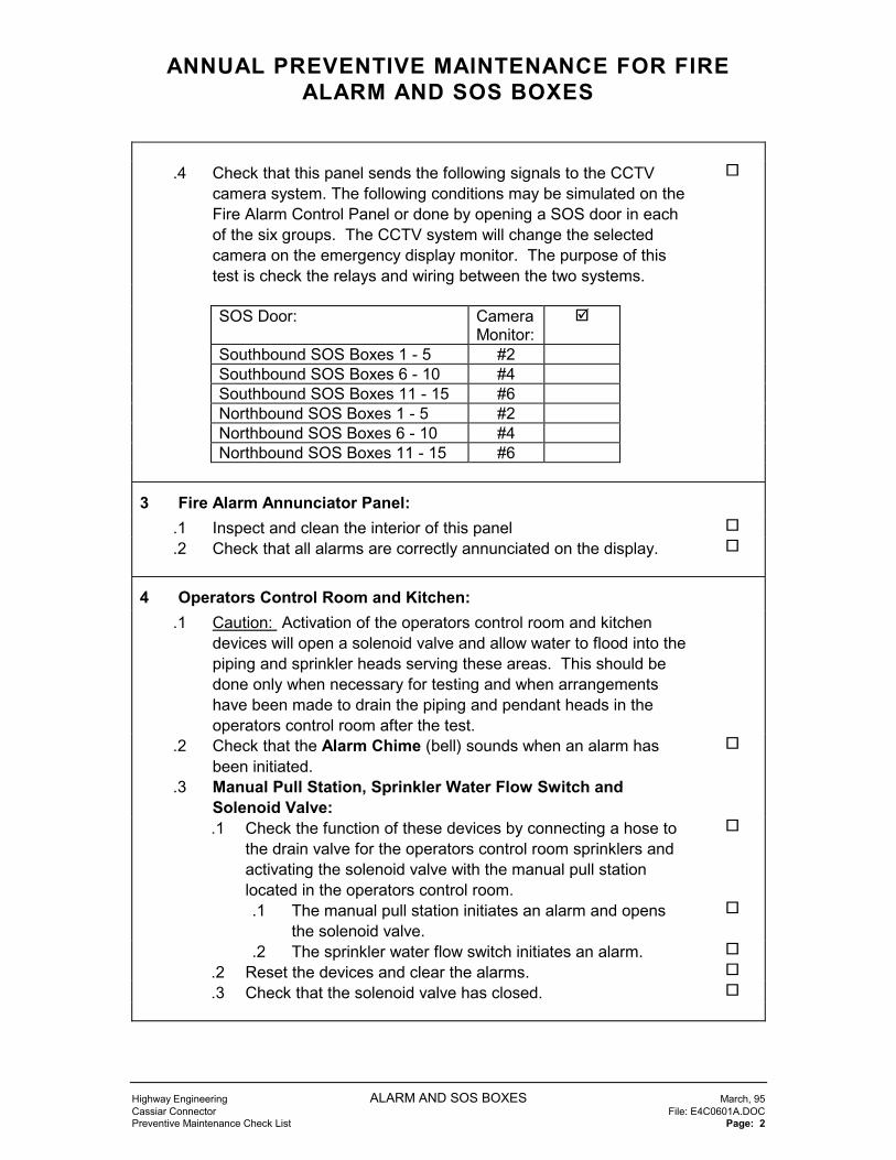
ANNUAL PREVENTIVE MAINTENANCE FOR FIREALARM AND SOS BOXES
Highway Engineering ALARM AND SOS BOXES March, 95Cassiar Connector File: E4C0601A.DOCPreventive Maintenance Check List Page: 2
.4 Check that this panel sends the following signals to the CCTVcamera system. The following conditions may be simulated on theFire Alarm Control Panel or done by opening a SOS door in eachof the six groups. The CCTV system will change the selectedcamera on the emergency display monitor. The purpose of thistest is check the relays and wiring between the two systems.
�
SOS Door: CameraMonitor:
�
Southbound SOS Boxes 1 - 5 #2Southbound SOS Boxes 6 - 10 #4Southbound SOS Boxes 11 - 15 #6Northbound SOS Boxes 1 - 5 #2Northbound SOS Boxes 6 - 10 #4Northbound SOS Boxes 11 - 15 #6
3 Fire Alarm Annunciator Panel:.1 Inspect and clean the interior of this panel �
.2 Check that all alarms are correctly annunciated on the display. �
4 Operators Control Room and Kitchen:.1 Caution: Activation of the operators control room and kitchen
devices will open a solenoid valve and allow water to flood into thepiping and sprinkler heads serving these areas. This should bedone only when necessary for testing and when arrangementshave been made to drain the piping and pendant heads in theoperators control room after the test.
.2 Check that the Alarm Chime (bell) sounds when an alarm hasbeen initiated.
�
.3 Manual Pull Station, Sprinkler Water Flow Switch andSolenoid Valve:.1 Check the function of these devices by connecting a hose to
the drain valve for the operators control room sprinklers andactivating the solenoid valve with the manual pull stationlocated in the operators control room.
�
.1 The manual pull station initiates an alarm and opensthe solenoid valve.
�
.2 The sprinkler water flow switch initiates an alarm. �
.2 Reset the devices and clear the alarms. �
.3 Check that the solenoid valve has closed. �

ANNUAL PREVENTIVE MAINTENANCE FOR FIREALARM AND SOS BOXES
Highway Engineering ALARM AND SOS BOXES March, 95Cassiar Connector File: E4C0601A.DOCPreventive Maintenance Check List Page: 3
.4 Kitchen Heat Detector:.1 Check the alarm function using a heat gun on a low setting. �
.2 Check the tamper/trouble function by removing the detectorfrom its base.
�
.3 Check that the solenoid valve opens �
.4 Reset the device and clear the alarms. �
.5 Check that the solenoid valve has closed. �
.5 Operators Control Room Smoke Detector:.1 Check the alarm function using a smoke source to activate
the detector.�
.2 Check the trouble function by removing the detector from itsbase.
�
.3 Check that the solenoid valve opens �
.4 Reset the device and clear the alarms. �
.5 Check that the solenoid valve has closed. �
5 Control Building Smoke Detectors:.1 Check the alarm function using a smoke source to activate each
device.�
.2 Check the tamper/trouble function by removing the detector fromits base.
�
6 Control Building and Diesel Storage Heat Detectors:.1 Check the alarm function using a heat gun. Do not overheat. �
.2 Check the tamper/trouble function by removing the detector fromits base.
�
7 Corridor Manual Pull Station:.1 Check the alarm function by opening the station with a screwdriver
and operating the switch.�
.2 Reset the switch and close the case. �
8 Control Building Door Switches:.1 These switches are currently not in service. They are not required
while the tunnel has a full time operator. The wiring and switcheshave been left in place.

ANNUAL PREVENTIVE MAINTENANCE FOR FIREALARM AND SOS BOXES
Highway Engineering ALARM AND SOS BOXES March, 95Cassiar Connector File: E4C0601A.DOCPreventive Maintenance Check List Page: 4
9 Gate Valve Tamper Switches:.1 Check the supervisory alarm function of the gate valve tamper
switches by partially closing the valves, waiting for the alarm andthen opening the valve.
�
.2 Note: The mounting of the switches makes them difficult to resetonce they have been moved. (the north valve pit is very touchy!)
.3 The switches on each valve in the north valve pit are wired inseries as one device - test each switch then reset.
.4 The switches on each valve in the south valve pit are wired inseries as one device.
10 SOS Door Switches:.1 Do the monthly check. �
11 SOS Manual Pull Stations.1 Check the alarm function by opening the station with a screwdriver
and operating the switch.�
.2 Wait for the alarm, reset the switch and close the case. �
12 Tunnel Heat Detectors.1 Check the alarm function using a heat gun. Do not overheat. �
.2 Check the tamper/trouble function by removing the detector fromits base.
�
13 Record Test Results:Abbreviations:
FACP - Fire Alarm Control PanelFAAP - Fire Alarm Annunciator PanelMPS - Manual Pull StationAC - Alarm ChimeHD - Heat DetectorSD - Smoke DetectorDS - Door SwitchGVTS - Gate Valve Tamper SwitchFS - Flow SwitchSV - Solenoid ValveSB - Southbound TunnelNB - Northbound TunnelN/A - Not Applicable

ANNUAL PREVENTIVE MAINTENANCE FOR FIREALARM AND SOS BOXES
Highway Engineering ALARM AND SOS BOXES March, 95Cassiar Connector File: E4C0601A.DOCPreventive Maintenance Check List Page: 5
Location Dev. ZoneandAddress
FACP �
FAAP �
CCTV�
SB-SOS Box-1 MPS 30-101 N/ADS 60-102
tunnel ceiling HD 10-103 N/Atunnel ceiling HD 10-103 N/Atunnel ceiling HD 10-103 N/A
SB-SOS Box-2 MPS 31-104 N/ADS 60-105
tunnel ceiling HD 11-106 N/Atunnel ceiling HD 11-106 N/Atunnel ceiling HD 11-106 N/A
SB-SOS Box-3 MPS 32-107 N/ADS 60-108
SB-SOS Box-4 MPS 33-109 N/ADS 60-110
tunnel ceiling HD 12-111 N/Atunnel ceiling HD 12-111 N/Atunnel ceiling HD 12-111 N/Atunnel ceiling HD 12-111 N/A
SB-SOS Box-5 MPS 39-201 N/ADS 60-202
tunnel ceiling HD 13-203 N/Atunnel ceiling HD 13-203 N/Atunnel ceiling HD 13-203 N/A
SB-SOS Box-6 MPS 35-204 N/ADS 61-205
SB-SOS Box-7 MPS 36-206 N/ADS 61-207
tunnel ceiling HD 14-208 N/Atunnel ceiling HD 14-208 N/Atunnel ceiling HD 14-208 N/A
SB-SOS Box-8 MPS 37-209 N/ADS 61-210

ANNUAL PREVENTIVE MAINTENANCE FOR FIREALARM AND SOS BOXES
Highway Engineering ALARM AND SOS BOXES March, 95Cassiar Connector File: E4C0601A.DOCPreventive Maintenance Check List Page: 6
Location Dev. ZoneandAddress
FACP �
FAAP �
CCTV�
SB-SOS Box-9 MPS 38-211 N/ADS 61-212
tunnel ceiling HD 15-213 N/Atunnel ceiling HD 15-213 N/Atunnel ceiling HD 15-213 N/Atunnel ceiling HD 15-213 N/A
SB-SOS Box-10 MPS 39-214 N/ADS 61-215
tunnel ceiling HD 16-216 N/Atunnel ceiling HD 16-216 N/Atunnel ceiling HD 16-216 N/A
SB-SOS Box-11 MPS 40-217 N/ADS 62-218
SB-SOS Box-12 MPS 41-219 N/ADS 62-220
tunnel ceiling HD 17-221 N/Atunnel ceiling HD 17-221 N/Atunnel ceiling HD 17-221 N/A
SB-SOS Box-13 MPS 42-222 N/ADS 62-223
SB-SOS Box-14 MPS 43-224 N/ADS 63-225
tunnel ceiling HD 18-226 N/Atunnel ceiling HD 18-226 N/Atunnel ceiling HD 18-226 N/Atunnel ceiling HD 18-226 N/A
SB-SOS Box-15 MPS 44-227 N/ADS 62-228
tunnel ceiling HD 19-229 N/Atunnel ceiling HD 19-229 N/Atunnel ceiling HD 19-229 N/A
NB-SOS Box-1 MPS 45-301 N/ADS 63-302
tunnel ceiling HD 20-303 N/Atunnel ceiling HD 20-303 N/Atunnel ceiling HD 20-303 N/A
NB-SOS Box-2 MPS 46-305 N/ADS 63-306
tunnel ceiling HD 21-307 N/Atunnel ceiling HD 21-307 N/Atunnel ceiling HD 21-307 N/A

ANNUAL PREVENTIVE MAINTENANCE FOR FIREALARM AND SOS BOXES
Highway Engineering ALARM AND SOS BOXES March, 95Cassiar Connector File: E4C0601A.DOCPreventive Maintenance Check List Page: 7
Location Dev. ZoneandAddress
FACP �
FAAP �
CCTV�
NB-SOS Box-3 MPS 47-308 N/ADS 63-309
tunnel ceiling HD 22-310 N/Atunnel ceiling HD 22-310 N/Atunnel ceiling HD 22-310 N/Atunnel ceiling HD 22-310 N/A
NB-SOS Box-4 MPS 48-311 N/ADS 63-312
NB-SOS Box-5 MPS 49-401 N/ADS 63-402
tunnel ceiling HD 23-403 N/Atunnel ceiling HD 23-403 N/Atunnel ceiling HD 23-403 N/A
NB-SOS Box-6 MPS 50-404 N/ADS 64-405
NB-SOS Box-7 MPS 51-406 N/ADS 64-407
tunnel ceiling HD 24-408 N/Atunnel ceiling HD 24-408 N/Atunnel ceiling HD 24-408 N/A
NB-SOS Box-8 MPS 52-409 N/ADS 64-410
NB-SOS Box-9 MPS 53-411 N/ADS 64-412
tunnel ceiling HD 25-413 N/Atunnel ceiling HD 25-413 N/Atunnel ceiling HD 25-413 N/Atunnel ceiling HD 25-413 N/A
NB-SOS Box-10 MPS 54-414 N/ADS 64-415
tunnel ceiling HD 26-416 N/Atunnel ceiling HD 26-416 N/Atunnel ceiling HD 26-416 N/A
NB-SOS Box-11 MPS 55-417 N/ADS 65-418
NB-SOS Box-12 MPS 56-419 N/ADS 65-420
tunnel ceiling HD 27-421 N/Atunnel ceiling HD 27-421 N/Atunnel ceiling HD 27-421 N/A

ANNUAL PREVENTIVE MAINTENANCE FOR FIREALARM AND SOS BOXES
Highway Engineering ALARM AND SOS BOXES March, 95Cassiar Connector File: E4C0601A.DOCPreventive Maintenance Check List Page: 8
Location Dev. ZoneandAddress
FACP �
FAAP �
CCTV�
NB-SOS Box-13 MPS 57-422 N/ADS 65-423
tunnel ceiling HD 28-424 N/Atunnel ceiling HD 28-424 N/Atunnel ceiling HD 28-424 N/Atunnel ceiling HD 28-424 N/A
NB-SOS Box-14 MPS 58-425 N/ADS 65-426
NB-SOS Box-15 MPS 59-427 N/ADS 65-428
tunnel ceiling HD 29-429 N/Atunnel ceiling HD 29-429 N/Atunnel ceiling HD 29-429 N/A
North Valve Pit GVTS 67-430 N/ASouth Valve Pit GVTS 66-304 N/ADiesel storage vault HD 73-509 N/AElectrical Substation - East SD 72-505 N/AElectrical Substation - West SD 72-510 N/AMechanical room SD 79-511 N/AStorage room SD 79-514 N/ARadio room SD 79-506 N/ACorridor - East SD 70-503 N/ACorridor - East MPS 69-502 N/ACorridor - West SD 70-508 N/ATunnel access SD 79-507 N/ATelephone room SD 79-515 N/ABattery room SD 78-518 N/ABattery room HD 79-516 N/AGenerator room HD 76-517 N/AMechanical room SD 79-511 N/AOperators control room MPS 80-520 N/AOperators control room SD 80-521 N/AKitchen HD 77-519 N/AMechanical room FS 74-512 N/AMechanical room GVTS 75-513 N/AControl Building ceiling SV N/A N/A N/AOperators control room AC N/A N/A N/AControl building main entrance DS 68-501 not in use N/ASubstation double doors DS 71-504 not in use N/A

ANNUAL PREVENTIVE MAINTENANCE FORSTANDPIPE
Highway Engineering STANDPIPE SYSTEM March, 95Cassiar Connector File: E4C0602A.DOCPreventive Maintenance Check List Page: 1
Item: �
1 General:.1 The maintenance listed in this table shall be done once a year
prior to the heating season..2 Notify tunnel operator 48 hours prior to maintenance..3 This PM shall not be performed during rush hours or emergencies.
2 Equipment:.1 The following equipment is located in the mechanical room:
.1 Pump PP-C-1
.2 Pump PP-C-2
.3 Differential Pressure Transducer
.4 Boiler WH-C-1, High Limit Switch, Low Water Cut-off
.5 Water Temperature Sensor
.6 Water Pressure Sensor
.7 Leak Detector.2 The Outside Air Temperature Sensor is located on the roof.3 The Heat Tracing is located on the 30 pipes feeding the fire hose
connections in each SOS box from the Main Standpipe Header inthe southbound tunnel.
3 Lock-out:.1 Refer to the Lock-out Section 103 of the Cassiar Tunnel Electrical
Maintenance Standards manual.
4 Boiler, pumps and related checks:.1 Switch-off the following equipment at the local disconnect.
.1 Pump PP-C-1 �
.2 Pump PP-C-2 �
.3 Boiler WH-C-1 �
.2 Check and record the phase to phase heating element resistance.This should be 52 ohms.
C1 C2 C3A - BB - CC - A
.3 Check and record the insulation resistance. This should begreater than 500,000 ohms. C1 _____ C2 _____ C3 _____
.4 Check the wiring and tighten connections. �

ANNUAL PREVENTIVE MAINTENANCE FORSTANDPIPE
Highway Engineering STANDPIPE SYSTEM March, 95Cassiar Connector File: E4C0602A.DOCPreventive Maintenance Check List Page: 2
.5 Switch-on the following equipment..1 Pump PP-C-1 �
.2 Pump PP-C-2 �
.3 Boiler WH-C-1 �
.6 Check Honeywell water temperature sensor reading forreasonableness.
�
.7 Enable the boiler and pumps by overriding the Honeywell watertemperature sensor input as follows:.1 7�C. - Pump PP-C-1 on �
.2 4�C. - Boiler Stage 1 heat on �
.3 3�C. - Boiler Stage 2 heat on �
.3 2�C. - Boiler Stage 3 heat on �
.8 Check Honeywell water temperature sensor reading forreasonableness.
�
.9 Check the operation of the Water Pressure Sensor:.1 Note the setting on the pressure switch. �
.2 Lower the setting below the current pressure and check forthe Honeywell Alarm and Boiler shutdown.
�
.3 Reset the pressure switch to the original setting. �
.10 Push-to Test the boiler low water cut-out. The boiler should switchoff.
�
.11 Test the operation of the standby pump PP-C-2:.1 Switch of the local disconnect for PP-C-1 �
.2 Note the Honeywell alarm �
.3 PP-C-2 should start after a 60 second delay. �
.4 Switch on the local disconnect for PP-C-1 �
.12 Circulation pumps PP-C-1 and PP-C-2:.1 Visually check for leakage from the mechanical seals. �
.2 Check for excessive vibration and bearing noise. �
.13 Return the Honeywell water temperature to automatic ( no override) operation.
�
.14 Check the operation of the leak detector located on the floor by thewest wall..1 Place a wet rag gently under the housing to make contact with
the sensing probes.�
.2 Check the Honeywell alarm. �

ANNUAL PREVENTIVE MAINTENANCE FORSTANDPIPE
Highway Engineering STANDPIPE SYSTEM March, 95Cassiar Connector File: E4C0602A.DOCPreventive Maintenance Check List Page: 3
5 Heat tracing checks:.1 Enable the heat tracing by overriding the Honeywell water
temperature sensor input to less than 3�C.�
.2 Check and record the load on each circuit on Panel H. Comparethese to previous values and investigate significant differences.
�
.3 Check the operation of each heat tracing tape at the SOS box andthe north and south valve pits. They should be warm to the touch.
�
.4 Switch off each heat tracing circuit breaker in turn at panel H andcheck the Honeywell alarms.
�
Circuit Load amps Feels warm Alarm� �
1 - Valve Pit2 - Valve Pit3 - SOS 14 - SOS 25 - SOS 36 - SOS 47 - SOS 58 - SOS 69 - SOS 710 - SOS 811 - SOS 912 - SOS 1013 - SOS 1114 - SOS 1215 - SOS 1316 - SOS 1417 - SOS 15
.5 Return the Honeywell water temperature to automatic ( no override) operation.
�
5 Final checks:.1 Ensure that no Honeywell or fire alarm panel alarms are present. �

FIVE-YEAR PREVENTIVE MAINTENANCE FORSTANDPIPE
Highway Engineering STANDPIPE SYSTEM March, 95Cassiar Connector File: E4C0602F.DOCPreventive Maintenance Check List Page: 1
Item: �
1 General:.1 The maintenance listed in this table shall be done once every five
years prior to the heating season..2 This maintenance shall be done with the annual PM..3 Notify tunnel operator 48 hours prior to maintenance..4 This PM shall not be performed during rush hours or emergencies..5 This maintenance shall be done by a tradesman qualified, trained
and competent to service electric hot water boilers.
2 Equipment:.1 Boiler WH-C-1 is located in the mechanical room.
3 Boiler checks:.1 Blow down the boiler and inspect the elements.
.1 Close the inlet and outlet valves. �
.2 Drain the boiler. �
.3 Open the inspection door and examine the scale build-up onthe elements. If greater than 1/32” then remove elements,clean, replace and close inspection door.
�
.4 Close the drain and open the inlet and outlet valves to refillboiler.
�

MONTHLY PREVENTIVE MAINTENANCE FOREMERGENCY GENERATOR
Highway Engineering EMERGENCY GENERATOR March, 95Cassiar Connector File: E4C0701M.DOCPreventive Maintenance Check List Page: 1
Item: �
1 General:.1 The maintenance listed in this table shall be done once a month..2 Notify tunnel operator 48 hours prior to maintenance..3 This maintenance shall be done during the day ( the noise level is
too high for evening or early morning operation)..4 This maintenance shall not be performed during rush hours or
emergencies..5 Notify the cellular telephone utility if any service interruptions are
anticipated. The cellular service is not on the UPS and isinterrupted whenever normal hydro is switched.
.6 These checks shall be done in the listed sequence.
2 Equipment:.1 Engine section - generator room..2 Alternator section - generator room..3 Attached generator control panel - cabinet mounted on top of
alternator..4 Detached generator control panel with breaker - dark blue cabinet
in the generator room..5 Remote transfer switches (dark blue) and related control panels
(light blue) in the substation..6 Ventilation system - generator room..7 Fuel system - generator room, fuel pump PP-C-3 and outside fuel
tank..8 Honeywell computer - control room and substation.
3 Warnings and Cautions:.1 The generator may start automatically..2 Refer to posted warnings..3 Do not use the generator emergency stop switches located outside
the generator room door or on the attached generator controlpanel unless the generator is in a “run - away” condition or thedisconnects do not operate and there is an emergency situation.The use of these switches may cause serious engine damage.
�

MONTHLY PREVENTIVE MAINTENANCE FOREMERGENCY GENERATOR
Highway Engineering EMERGENCY GENERATOR March, 95Cassiar Connector File: E4C0701M.DOCPreventive Maintenance Check List Page: 2
4 Lock-out:.1 Refer to the Lock-out Section 103 of the Cassiar Tunnel Electrical
Maintenance Standards manual..2 A maintenance lock-out point is provided on the detached
generator control panel for service of the engine and alternatorsections.
5 Prestart checks:.1 Ensure that Emergency Backup Panel door in the operators’
control room is closed and locked. The generator load breaker willtrip if there are fans turned on using this panel. The Honeywellcomputer will automatically turn off fans which are running undercomputer control.
�
.2 Ask the tunnel operator to display the Battery room on theHoneywell computer and check that no UPS alarms are present.
�
.3 Ask the tunnel operator to display the Generator room on theHoneywell computer and check the following information:
�
.1 generator is not operating �
.2 has not failed Hydro �
.3 outdoor supply air dampers are closed �
.4 exhaust air dampers are closed �
.5 recirculation air dampers are open �
.6 no alarms are present: �
.7 space temperature (range 12-28� C.) �
.8 Check and record the main fuel tank Honeywell Computerlevel indication ________ gallons.
�
.4 Check and record the main fuel tank level using the calibrated dipstick and chart on side of day tank _______ litres. Also record thelevel in generator log book.
�
.5 Check and record the main fuel tank level using the pneumaticlevelometer located on outside of north wall of control building________ litres
�
.6 Ensure that the generator room and equipment are clean and freeof loose objects.
�
.7 Ensure that ventilation intake louvers and plenum are clean andclear of loose objects.
�
.8 Inspect for leaks:.1 coolant �
.2 lubricating oil �
.3 fuel oil �

MONTHLY PREVENTIVE MAINTENANCE FOREMERGENCY GENERATOR
Highway Engineering EMERGENCY GENERATOR March, 95Cassiar Connector File: E4C0701M.DOCPreventive Maintenance Check List Page: 3
.9 Check fluid levels:.1 battery �
.2 engine oil dipstick �
.3 engine coolant - visual check through filler cap �
.4 fuel day tank - visual check through pipe cap �
.10 Test run the fuel pump PP-C-3 using the local controller panel -return to automatic control after one minute test.
�
.11 Record date and engine hours in generator log book �
.12 Check status of generator alarm indication lights on detachedpanel. No alarms should be present. Press lamp test. Relamp asnecessary.
�
.13 Check battery charging voltage on panel meter. This should begreater than 25.5 volts.
�
.14 Check that the engine block heater is working. The engine blockshould be warm to the touch.
�
.15 Check that the emergency stop flaps on the generator air intakeare latched open (normal position).
�
.16 Check the status of the disconnect and transfer switches:.1 generator room electrical panel ( dark blue ): main breaker
‘charged’ and ‘closed’�
.2 sub-station secondary main breaker ( light blue ) : ‘charged’and ‘closed’
�
.3 emergency bypass (dark blue): ‘open ’and ‘locked’ �
.4 emergency breaker (dark blue): ‘open’, ‘unlocked’ and‘charged’
�
.5 normal breaker(dark blue): ‘closed’, ‘unlocked’ and ‘charged’, �
.6 normal bypass (dark blue): ‘open’ and ‘locked’ �
.17 Check UPS:.1 main switch is in the normal, on-line position �
.2 DC disconnect is “closed” �
.3 no alarms present on local UPS panel �
6 Operating Checks..1 The first generator run will test only the generator related functions
- not the electrical switch gear. This test is done in order to verifythat the engine functions prior to initiating a load test..1 turn the engine control selector switch located on the
detached generator control panel in the generator room to the“test” position.
�
.2 generator will run. �
.3 load will not transfer from Hydro. �

MONTHLY PREVENTIVE MAINTENANCE FOREMERGENCY GENERATOR
Highway Engineering EMERGENCY GENERATOR March, 95Cassiar Connector File: E4C0701M.DOCPreventive Maintenance Check List Page: 4
.2 Allow the generator to run for 10 minutes. Do not create anyconditions to simulate failure conditions.
�
.3 Check status of generator alarm indication lights on detachedgenerator control panel. No alarms should be present
�
.4 Check and record the frequency - meter (59-60 Hz.)actual: ________ Hz.
�
.5 Monitor and record the following from the gauges on the attachedgenerator control panel:.1 oil pressure ( normal range: 70 - 90 ) actual: _________ �
.2 coolant temperature: ( normal range: 170 - 200 ) actual: _________
�
.6 Check operation of generator ventilation system dampers:.1 outdoor supply air dampers are open �
.2 exhaust air dampers are open �
.3 recirculation dampers modulate to maintain 18.5� C. �
.7 Display the Generator room on the Honeywell computer and checkthe following information:.1 generator is operating �
.2 outdoor supply air dampers are open �
.3 exhaust air dampers are open �
.4 recirculation air dampers are open (modulating) �
.5 no alarms are present: �
.8 Turn the selector switch located on the detached generator controlpanel in the generator room to the “auto” position to stop thegenerator.
�
.9 The following generator test is done in order to verify the automaticoperation of the generator and transfer switches in the event ofHydro failure. Refer to the posted metal line drawing on thesubstation panel for circuit and breaker details..1 Open the secondary main breaker switch located on the (light
blue) control panel in the sub-station using the red “push toopen” button located inside the door. This will open thenormal Hydro low voltage supply and transfer load to theemergency generator.
�
.2 generator will start after few seconds delay. �
.3 normal breaker (dark blue) opens after few seconds delay. �
.4 emergency breaker (dark blue) closes after few secondsdelay.
�
.10 Check for alarms on the detached generator panel. �

MONTHLY PREVENTIVE MAINTENANCE FOREMERGENCY GENERATOR
Highway Engineering EMERGENCY GENERATOR March, 95Cassiar Connector File: E4C0701M.DOCPreventive Maintenance Check List Page: 5
.11 Display the Generator room on the Honeywell computer and checkthe following information:.1 generator is operating �
.2 Hydro has failed �
.3 check with tunnel operator for any alarms which have notreset after the generator is on line.
�
.12 Check UPS:.1 no alarms are present on local UPS panel. �
.2 emergency lighting and computer loads (see single linedrawing) were continuously fed from the UPS during thetransfer to the generator feed. The control room emergencylighting should stay on and there should not be any Honeywellpanel failure alarms.
�
.13 Load test:.1 Note: The UPS “Battery status alarm” on the Honeywell
computer may annunciate during the load test. This is OK asthe UPS is sensing the power fluctuations caused by theloading of the generator.
�
.2 Open Emergency Backup Panel door in the operators’ controlroom and start every other fan pair at approximately 3 secondintervals. Leave the door open for the duration of the test.
�
.3 Check and record the Frequency meter (Range: 59-61 Hz.)actual: ________ Hz. from the detached generator controlpanel.
�
.4 Check and record the voltage on each phase of the meters onthe detached generator control panel.A:_________ B:_________ C:_________
�
.5 Check and record the load on each phase of the meters onthe detached generator control panel.A:_________ B:_________ C:_________
�
.6 Run this test for 30 minutes. �
.7 Close and lock the Emergency Backup Panel door in theoperators’ control room. This will stop the fans.
�
.14 Close the secondary main breaker switch located on the (lightblue) control panel in the sub-station using the green “push toclose” button located inside the door. This will transfer load tonormal Hydro low voltage supply.
�
.15 Load transfer to Hydro:.1 emergency breaker (dark blue) opens after ____ second
delay.�
.2 normal breaker (dark blue) closes after ____ second delay. �
.16 The generator will stop after a 5 minute cool down period. �

MONTHLY PREVENTIVE MAINTENANCE FOREMERGENCY GENERATOR
Highway Engineering EMERGENCY GENERATOR March, 95Cassiar Connector File: E4C0701M.DOCPreventive Maintenance Check List Page: 6
7 Final checks (after generator stops):.1 Check the status of the disconnect and transfer switches:
.1 generator room electrical panel ( dark blue ): main breaker‘charged’ and ‘closed’
�
.2 sub-station secondary main breaker ( light blue ) : ‘charged’and ‘closed’
�
.3 emergency bypass ( dark blue ):‘open’ and ‘locked’ �
.4 emergency breaker( dark blue ): ‘open’, ‘unlocked’ and‘charged’
�
.5 normal breaker( dark blue ): ‘closed’, ‘unlocked’ and ‘charged’, �
.6 normal bypass ( dark blue ): ‘open’ and ‘locked’ �
.2 Check fuel level in day tank - visual check through pipe cap. �
.3 Check status of generator alarm indication lights on detachedpanel. No alarms should be present.
�
.4 Record engine hours in generator log book. �
.5 Check UPS: no alarms present on local UPS panel �
.6 Lock doors and return key �
.7 Check with tunnel operator and ensure that no alarms are presenton the Honeywell computer.
�

TRI-ANNUAL PREVENTIVE MAINTENANCE FOREMERGENCY GENERATOR
Highway Engineering EMERGENCY GENERATOR March, 95Cassiar Connector File: E4C0701T.DOCPreventive Maintenance Check List Page: 1
Item: �
1 General:.1 The maintenance listed in this table shall be done once every three
years in conjunction with a monthly preventive maintenance..2 A qualified Diesel generator service contractor shall be used..3 A person trained and familiar with the Honeywell computer and
control wiring shall be used.
2 Diesel Panel Alarms:.1 Simulate and check the status of the following alarm lamps on the
detached generator panel..1 under speed �
.2 low oil pressure �
.3 over voltage �
.4 over crank �
.5 switch abnormal �
.6 Hydro failure �
.7 high water temperature �
.8 frequency abnormal �
.9 under voltage �
.10 low day tank level �
.11 air flap closed �
.12 load on generator �
.13 battery level �
3 Honeywell Computer Alarms:.1 Simulate and check the status of the following alarms:
.1 generator not available �
.2 generator failed to start �
.3 generator over temperature �
.4 generator oil or water leak �
.5 oil storage tank leak �
.6 main tank high and low level �
.7 main tank level falling with pump off �
.8 day tank high level with pump on �
.9 day tank low level with pump off �
.10 Fuel oil transfer pump PP-C-3 failure �

MONTHLY PREVENTIVE MAINTENANCE FORUNINTERRUPTABLE POWER SUPPLY
Highway Engineering UNINTERRUPTABLE POWER SUPPLY March, 95Cassiar Connector File: E4C0702M.DOCPreventive Maintenance Check List Page: 1
Item: �
1 General:.1 The maintenance listed in this table shall be done once a month..2 Notify tunnel operator 48 hours prior to maintenance..3 This maintenance shall not be performed during rush hours or
emergencies..4 Notify the cellular telephone utility if any service interruptions are
anticipated. The cellular service is not on the UPS and isinterrupted whenever normal hydro is switched.
.5 The PM service of the UPS 30 KVA 600/206/120 Transformershall be done in conjunction with the Low Voltage Switch Gear.
.6 The PM service of the emergency distribution panels shall bedone in conjunction with the MCC Switch Gear and Panel Boards.
.7 These checks shall be done in the listed sequence.
2 Equipment:.1 UPS System Controller - Cabinet in battery room..2 Batteries - Rack mounted in battery room.3 DC Disconnect Switch - Wall mounted adjacent to UPS system
controller.4 30 KVA 600/206/120 - on floor on west side of battery.5 Emergency Distribution Panels (green):
.1 EN - 347/600V. north wall of battery room
.2 EA - 120/208V. north wall of battery room
.3 EG - 120/208V. east wall of operators’ control room
3 Warnings and Cautions:.1 The UPS may switch automatically..2 Refer to posted warnings..3 The “off” - “0” position on the UPS rotary switch turns off (opens)
the input power feeds to the UPS from any source - Hydro,emergency generator or the batteries. The output feed to thethree emergency power distribution panels is also open and theequipment fed from these panels will not be powered.
.4 An immediate loss of power will occur to the equipment fed fromthe three emergency power distribution panels if the rotary handleis operated during a power failure (Hydro and/or EmergencyGenerator).
.5 The “Time Remaining” message displayed by the UPS is notaccurate and shall not be used.

MONTHLY PREVENTIVE MAINTENANCE FORUNINTERRUPTABLE POWER SUPPLY
Highway Engineering UNINTERRUPTABLE POWER SUPPLY March, 95Cassiar Connector File: E4C0702M.DOCPreventive Maintenance Check List Page: 2
4 Lock-out:.1 Refer to the Lock-out Section 103 of the Cassiar Tunnel Electrical
Maintenance Standards manual.
5 UPS Console Checks:.1 Ask the tunnel operator to display the Battery/UPS room on the
Honeywell computer and check that the UPS battery chargingalarm is normal.
�
.2 Ensure that the battery room and equipment are clean and free ofloose objects.
�
.3 Check the Digital Display Screen on the UPS cabinet door. Themessage will read “Normal Operation” indicating that the UPS iscurrently OK.
�
.4 Display and record in the log the metering functions by pressingthe down arrow on the UPS cabinet door until the followinginformation is displayed:
�
LOAD: _____ %A PHASE: _____ KVAB PHASE: _____ KVAC PHASE: _____ KVA
DC BUS:Voltage _____Amps _____Charging/Discharging _____
INPUT A - PHASE: INPUT B - PHASE: INPUT C -PHASE:A - B _____ VOLTS B - C _____ VOLTS C - A _____VOLTSA - N _____ VOLTS B - N _____ VOLTS C - N _____VOLTSA _____ AMPS B _____ AMPS C _____AMPS
OUTPUT A - PHASE: OUTPUT B - PHASE: OUTPUT C -PHASE:A - B _____ VOLTS B - C _____ VOLTS C - A _____VOLTSA - N _____ VOLTS B - N _____ VOLTS C - N _____VOLTSA _____ AMPS B _____ AMPS C _____AMPS
FREQUENCY:OUTPUT _____ Hz INPUT _____ Hz

MONTHLY PREVENTIVE MAINTENANCE FORUNINTERRUPTABLE POWER SUPPLY
Highway Engineering UNINTERRUPTABLE POWER SUPPLY March, 95Cassiar Connector File: E4C0702M.DOCPreventive Maintenance Check List Page: 3

MONTHLY PREVENTIVE MAINTENANCE FORUNINTERRUPTABLE POWER SUPPLY
Highway Engineering UNINTERRUPTABLE POWER SUPPLY March, 95Cassiar Connector File: E4C0702M.DOCPreventive Maintenance Check List Page: 4
.5 Display and record the alarm history:.1 Press the down arrow on the UPS cabinet door until “Alarm
History” is displayed.�
.2 Press the alarm silence pad to access the Alarm Historyscreen.
�
.3 Press the down arrow to display any messages. �
.4 Record the date, time and description of any messages whichhave occurred since the last PM.
�
.6 Check the LCD display segments (equivalent of a lamp test):.1 Press the up arrow from the NORMAL OPERATION default
screen.�
.1 All LCD segments activate �
.2 The alarm sounds �
.7 Check that both LEDs on the power status diagram are on. �
.8 Check the condition of the UPS cabinet air filter. Replace if dirty.Note: a two piece filter is required as the door does not open wideenough to accommodate a single filter.
�
6 Final checks:.1 Check the Digital Display Screen on the UPS cabinet door. The
message will read “Normal Operation” indicating that the UPS iscurrently OK.
�
.2 Record PM visit in log book. Note any corrective action taken. �
.3 Lock doors and return key �

ANNUAL PREVENTIVE MAINTENANCE FORUNINTERRUPTABLE POWER SUPPLY
Highway Engineering UNINTERRUPTABLE POWER SUPPLY March, 95Cassiar Connector File: E4C0702A.DOCPreventive Maintenance Check List Page: 1
Item: �
1 General:.1 The maintenance listed in this table shall be done once a year..2 This shall be scheduled in conjunction with a monthly UPS
preventive maintenance..3 This maintenance shall be done by the UPS supplier’s
representative or a qualified electrician with specific servicetraining for this UPS. Some of the following tests require expertinterpretation of the results.
2 Wiring:.1 Check that the insulation is in good condition and that connections
are tight for the following wiring groups: .1 DC disconnect switch. �
.2 Emergency distribution panels (3-Green). �
3 UPS Console Checks (to be done in sequence):.1 Record AC input voltage to UPS at input fuses using a digital volt
meter (DVM): A-B _____ B-C _____ C-A _____.2 Rotate UPS rotary selector switch to position 1- Bypass. ( not 0 !) �
.3 Check Honeywell DDC UPS charging alarm is “on”. �
.4 Check all console nuts, bolts, screws and connectors for tightnessincluding:.1 Ribbon connectors �
.2 Power pole bolts �
.3 DC Capacitor screws �
.5 inspect for broken. damaged or burned components or cable. �
.6 Replace power capacitors showing swelling, leakage or extrudedvents.
�
.7 Clean interior and exterior of cabinet. �
.8 Measure and record DC Bus ripple: _____ MV.
.9 Rotate UPS rotary selector switch clockwise to position 2- UPSStart.
�
.10 Measure and record the following REGULATED power supplyvoltages:
+5VDC _____ +10VDC _____+12VDC _____ -12VDC _____
.11 Check Honeywell DDC UPS charging alarm is reset “off”. �

ANNUAL PREVENTIVE MAINTENANCE FORUNINTERRUPTABLE POWER SUPPLY
Highway Engineering UNINTERRUPTABLE POWER SUPPLY March, 95Cassiar Connector File: E4C0702A.DOCPreventive Maintenance Check List Page: 2
.12 Measure and record the following UNREGULATED power supplyvoltages with the module not running:
+24VDC _____ -24VDC _____.13 Measure and record the following voltages at the AC output
terminal strip:A-B _____ B-C _____ C-A _____A-N _____ B-N _____ C-N _____
.14 Measure, adjust if necessary and record DC Bus voltage: ____408 VDC
.15 Rotate UPS rotary selector switch clockwise to position 3- UPSCheck.
�
.16 Rotate UPS rotary selector switch clockwise to position 4- ONUPS.
�
.17 Measure and record the following UNREGULATED power supplyvoltages with the module running:
+24VDC _____ -24VDC _____.18 Perform Monthly UPS Console Checks. �
.19 Test UPS line failure switching by opening “UPS” substationbreaker.
�
.20 Return to normal Hydro power by closing “UPS” substationbreaker.
�
4 UPS Substation Breaker:.1 This breaker shall be serviced with the sub-station switch gear.

ANNUAL PREVENTIVE MAINTENANCE FORUNINTERRUPTABLE POWER SUPPLY
Highway Engineering UNINTERRUPTABLE POWER SUPPLY March, 95Cassiar Connector File: E4C0702A.DOCPreventive Maintenance Check List Page: 3
5 Battery Checks:.1 Visually inspect :
.1 Supplier product warning labels. �
.2 Battery electrolyte levels - between 5 mm and 55 mm aboveplates.
�
.3 Batteries -for swelling, leaks, dirt and foreign objects. �
.4 Cables and connectors - for overheating, corrosion anddamage.
�
.5 Mounting racks - structural integrity and corrosion. �
.2 Addition of distilled water:.1 Use protective clothing - face shield, rubber gloves, etc..2 Use only distilled water from a closed container..3 Use only the tools kept in the battery room. Do not use tools
such as hydrometers, funnels, dip tubes or filling bulbs whichhave been used for other types of batteries - especially leadacid.
.3 Cleaning of battery cell covers:.1 Use protective clothing - face shield, rubber gloves, etc..2 Use warm water and a mild detergent with a cloth on a
wooden stick to remove any salt deposits. Do not usehydrocarbon based cleaners.
.3 Do not coat battery terminals; especially not with grease..4 Torque all battery connections to 36 NM. �

ANNUAL PREVENTIVE MAINTENANCE FOR THE LANESIGNAL CONTROLLER AND SIGNAL HEADS
Highway Engineering LANE SIGNAL CONTROLLER AND SIGNAL HEADS March, 95Cassiar Connector File: E4C0801A.DOCPreventive Maintenance Check List Page: 1
Item: �
1 General:.1 The maintenance listed in this table shall be done once a year..2 Notify tunnel operator 48 hours prior to maintenance..3 This maintenance shall not be performed during rush hours or
emergencies..4 The tunnel portion of this work will require the use of a bucket
truck..5 Lane closures will be required. �
2 Equipment:.1 The Lane Signal Controller is located on the south wall of the
operators control room..2 The Lane Signal Heads are located in the northbound and
southbound tunnels - 4 signal heads per lane ( 8 per tunnel )..3 Each signal head has 3 primary and 3 secondary halogen bulbs
8000 hour - GE Q50MR16/FL/1/ENL 12V 50W Narrow Flood 32�
3 Warnings and Cautions:.1 Take note of separate power source within the lane signal
controller.�
4 Lock-out:.1 Refer to the Lock-out Section 103 of the Cassiar Tunnel Electrical
Maintenance Standards manual.
5 Annual re-lamp:.1 Place lane closure in effect for lane to be re-lamped. �
.2 Switch off the Lane Signal Controller for the lane being serviced.The 4 toggle switches are located inside the lane control cabinet.
�
.3 Switch off the power supply to the signal heads for the tunnelbeing serviced: Panel EA , cct. 13 is south bound, cct. 15 is northbound,
�
.4 Replace the bulbs. �
.5 Clean inside of the lens. �
.6 Check gasket condition. �

ANNUAL PREVENTIVE MAINTENANCE FOR THE LANESIGNAL CONTROLLER AND SIGNAL HEADS
Highway Engineering LANE SIGNAL CONTROLLER AND SIGNAL HEADS March, 95Cassiar Connector File: E4C0801A.DOCPreventive Maintenance Check List Page: 2
.7 Record (�) PM:SB Slow SB Fast NB Fast NB Slow
1 1 1 12 2 2 23 3 3 34 4 4 4
6 Lane Signal Controller:.1 Clean front panel. �
.2 Check fan operation. �
.3 Check the signal head lamp status: �
.1 Select each of the three states in turn and select note if anyLEDs are not illuminated. This indicates a faulty signal headlamp..1 Steady red. �
.2 Flashing amber. �
.3 Steady green. �
.2 Repeat the above for each of the steps on the Multipointcontroller. Manually select each step on the Multipointcontroller panel.
�
7 Final checks:.1 Switch on the Lane Signal Controller. �
.2 Switch on the power supply to the signal heads. �
.3 Drive through tunnel and check each of the three states for eachsignal head.
�
.4 Return the Lane Signal Controller and the Multipoint controller totheir normal operating condition.
�
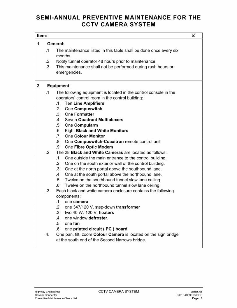
SEMI-ANNUAL PREVENTIVE MAINTENANCE FOR THECCTV CAMERA SYSTEM
Highway Engineering CCTV CAMERA SYSTEM March, 95Cassiar Connector File: E4C0901S.DOCPreventive Maintenance Check List Page: 1
Item: �
1 General:.1 The maintenance listed in this table shall be done once every six
months..2 Notify tunnel operator 48 hours prior to maintenance..3 This maintenance shall not be performed during rush hours or
emergencies.
2 Equipment:.1 The following equipment is located in the control console in the
operators’ control room in the control building:.1 Ten Line Amplifiers.2 One Compuswitch.3 One Formatter.4 Seven Quadrant Multiplexers.5 One Compularm.6 Eight Black and White Monitors.7 One Colour Monitor.8 One Compuswitch-Coaxitron remote control unit.9 One Fibre Optic Modem
.2 The 28 Black and White Cameras are located as follows:.1 One outside the main entrance to the control building..2 One on the south exterior wall of the control building..3 One at the north portal above the southbound lane..4 One at the south portal above the northbound lane..5 Twelve on the southbound tunnel slow lane ceiling..6 Twelve on the northbound tunnel slow lane ceiling.
.3 Each black and white camera enclosure contains the followingcomponents:.1 one camera.2 one 347/120 V. step-down transformer.3 two 40 W. 120 V. heaters.4 one window defroster..5 one fan.6 one printed circuit ( PC ) board
4. One pan, tilt, zoom Colour Camera is located on the sign bridgeat the south end of the Second Narrows bridge.

SEMI-ANNUAL PREVENTIVE MAINTENANCE FOR THECCTV CAMERA SYSTEM
Highway Engineering CCTV CAMERA SYSTEM March, 95Cassiar Connector File: E4C0901S.DOCPreventive Maintenance Check List Page: 2
5. The colour camera enclosure contains the following components:.1 one 1/3” CCD colour camera with 10X Zoom Lens.2 one window wiper.3 two 40 W. 120 V. heaters.4 one window defroster..5 one fan.6 one Pan/Tilt/Zoom, Voice/Data Multiplex Receiver/Driver
3 Equipment checks:.1 Clean the console area - vacuum behind the console. �
.2 Check the operation of the seven ventilation fans in the CCTVconsole.
�
.3 Check operation of the pan/tilt/zoom on the Second Narrowscamera.
�
.4 Check operation of the window wiper on the Second Narrowscamera.
�
.5 Visually check each monitor:.1 Quality of the video image. �
.2 Target area positioning: tunnel and emergency doorcoverage.
�
.6 Manually select each camera and verify the image on theemergency display monitor.
Camera: Quad. monitorimage: �
Emergencymonitor image:�
N-1N-2
S-13 portalParking area
N-3S-12N-4S-11N-5S-10N-6S-9N-7S-8N-8S-7

SEMI-ANNUAL PREVENTIVE MAINTENANCE FOR THECCTV CAMERA SYSTEM
Highway Engineering CCTV CAMERA SYSTEM March, 95Cassiar Connector File: E4C0901S.DOCPreventive Maintenance Check List Page: 3
N-9S-6N-10S-5N-11S-4N-12S-3
N-13 portalS-2S-1
2nd NarrowsEntrance small mon.

ANNUAL PREVENTIVE MAINTENANCE FOR THE CCTVCAMERAS
Highway Engineering CCTV CAMERA SYSTEM March, 95Cassiar Connector File: E4C0901A.DOCPreventive Maintenance Check List Page: 1
ANNUAL PREVENTIVE MAINTENANCE FOR CCTV CAMERAS
Item: �
1 General:.1 The maintenance listed in this table shall be done once every year
immediately prior to the heating season.�
.2 Notify tunnel operator 48 hours prior to maintenance. �
.3 This maintenance shall not be performed during rush hours oremergencies.
�
.4 The tunnel portion of this work will require the use of a buckettruck.
�
.5 Lane closures will be required. �
.6 Equipment located in the operators’ control room requires noannual maintenance.
�
2 Equipment:.1 The following equipment is located in the control console in the
operators’ control room in the control building:.1 Ten Line Amplifiers.2 One Compuswitch.3 One Formatter.4 Seven Quadrant Multiplexers.5 One Compularm.6 Eight Black and White Monitors.7 One Colour Monitor.8 One Compuswitch-Coaxitron remote control unit.9 One Fibre Optic Modem
.2 The twenty-eight Black and White Cameras are located asfollows:.1 One outside the main entrance to the control building..2 One on the south exterior wall of the control building..3 One at the north portal above the southbound lane..4 One at the south portal above the northbound lane..5 Twelve on the ceiling of the southbound tunnel above the slow
lane..6 Twelve on the ceiling of the northbound tunnel above the slow
lane.

ANNUAL PREVENTIVE MAINTENANCE FOR THE CCTVCAMERAS
Highway Engineering CCTV CAMERA SYSTEM March, 95Cassiar Connector File: E4C0901A.DOCPreventive Maintenance Check List Page: 2
.3 Each black and white camera enclosure has the followingcomponents:.1 one camera.2 one 347/120 V. step-down transformer.3 two 40 W. 120 V. heaters.4 one window defroster..5 one fan.6 one printed circuit ( PC ) board
4. One pan, tilt, zoom Colour Camera is located on the sign bridgeat the south end of the Second Narrows bridge.
5. The colour camera enclosure contains the following components:.1 one 1/3” CCD colour camera with 10X Zoom Lens.2 one window wiper.3 two 40 W. 120 V. heaters.4 one window defroster..5 one fan.6 one Pan/Tilt/Zoom, Voice/Data Multiplex Receiver/Driver
6. One Fibre Optic Modem is located at the base of the sign bridgeat the south end of the Second Narrows bridge.
3 Lock-out:.1 Refer to the Lock-out Section 103 of the Cassiar Tunnel Electrical
Maintenance Standards manual.�
.2 Isolate only one tunnel at a time for service.
.3 Panel EN cct. 13 & 15 feed the north bound tunnel cameras.
.4 Panel EN cct. 14 & 16 feed the south bound tunnel cameras.
.5 Panel EC cct. 7 feeds the door monitor and camera.
.6 The Second Narrows camera is fed from the power supply for thesign bridge.

ANNUAL PREVENTIVE MAINTENANCE FOR THE CCTVCAMERAS
Highway Engineering CCTV CAMERA SYSTEM March, 95Cassiar Connector File: E4C0901A.DOCPreventive Maintenance Check List Page: 3
4 Equipment Checks:.1 Cameras:
.1 Inspect exterior of enclosure and mounting hardware forphysical damage, cleanliness, paint finish, corrosion andsecurity.
�
.2 Interior of the enclosure:.1 Clean the interior. �
.2 Check for signs of moisture. �
.3 Check operation the following components using a cold spray..1 two heaters. �
.2 window defroster. �
.4 Check operation of the blower. �
.5 Record PM (�):
Camera: Mountingandexterior:
Interior: Heater andbloweroperation:
� � �
EntranceParking area
N- 1N- 2N- 3N- 4N- 5N- 6N- 7N- 8N- 9N-10N-11N-12
N-13 portal

ANNUAL PREVENTIVE MAINTENANCE FOR THE CCTVCAMERAS
Highway Engineering CCTV CAMERA SYSTEM March, 95Cassiar Connector File: E4C0901A.DOCPreventive Maintenance Check List Page: 4
Camera: Mountingandexterior:
Interior: Heater andbloweroperation:
S- 1S- 2S- 3S- 4S- 5S- 6S- 7S- 8S- 9S-10S-11S-12
S-13 portal2nd Narrows
.6 Check operation of the pan/tilt/zoom on 2nd Narrows camera. �
.7 Check operation of the window wiper on 2nd Narrows camera. �
5 Final checks:.1 Check the display on all monitors. �
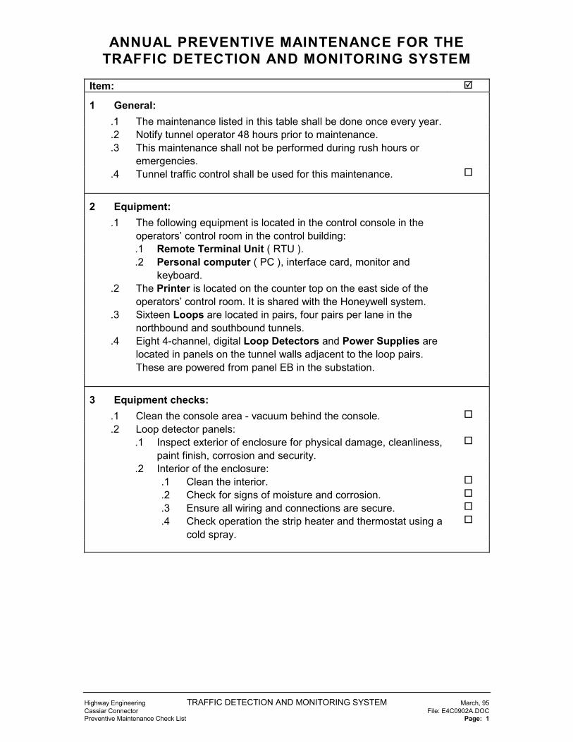
ANNUAL PREVENTIVE MAINTENANCE FOR THETRAFFIC DETECTION AND MONITORING SYSTEM
Highway Engineering TRAFFIC DETECTION AND MONITORING SYSTEM March, 95Cassiar Connector File: E4C0902A.DOCPreventive Maintenance Check List Page: 1
Item: �
1 General:.1 The maintenance listed in this table shall be done once every year..2 Notify tunnel operator 48 hours prior to maintenance..3 This maintenance shall not be performed during rush hours or
emergencies..4 Tunnel traffic control shall be used for this maintenance. �
2 Equipment:.1 The following equipment is located in the control console in the
operators’ control room in the control building:.1 Remote Terminal Unit ( RTU )..2 Personal computer ( PC ), interface card, monitor and
keyboard..2 The Printer is located on the counter top on the east side of the
operators’ control room. It is shared with the Honeywell system..3 Sixteen Loops are located in pairs, four pairs per lane in the
northbound and southbound tunnels..4 Eight 4-channel, digital Loop Detectors and Power Supplies are
located in panels on the tunnel walls adjacent to the loop pairs.These are powered from panel EB in the substation.
3 Equipment checks:.1 Clean the console area - vacuum behind the console. �
.2 Loop detector panels:.1 Inspect exterior of enclosure for physical damage, cleanliness,
paint finish, corrosion and security.�
.2 Interior of the enclosure:.1 Clean the interior. �
.2 Check for signs of moisture and corrosion. �
.3 Ensure all wiring and connections are secure. �
.4 Check operation the strip heater and thermostat using acold spray.
�

ANNUAL PREVENTIVE MAINTENANCE FOR THETRAFFIC DETECTION AND MONITORING SYSTEM
Highway Engineering TRAFFIC DETECTION AND MONITORING SYSTEM March, 95Cassiar Connector File: E4C0902A.DOCPreventive Maintenance Check List Page: 2
Loopdetector
Exteriorinspection:
Interiorinspection:
Heateroperation:
panel � � �
NB-1NB-2NB-3NB-4SB-1SB-2SB-3SB-4
.3 Operational checks of the loop detectors:.1 Close a lane of traffic. �
.2 Park a vehicle over each loop ( one at a time ) �
.3 Check the indication on the operators’ control room monitor. �
.4 Remove the vehicle from the loop area and note the delaytime until the indication resets on the operators’ control roommonitor.
�
.5 Repeat for each of the 32 loops. �
Loop: Reset delay: Loop: Reset delay:� �
NB-1A-Fast SB-1A-FastNB-1B-Fast SB-1B-FastNB-1A-Slow SB-1A-SlowNB-1B-Slow SB-1B-SlowNB-2A-Fast SB-2A-FastNB-2B-Fast SB-2B-FastNB-2A-Slow SB-2A-SlowNB-2B-Slow SB-2B-SlowNB-3A-Fast SB-3A-FastNB-3B-Fast SB-3B-FastNB-3A-Slow SB-3A-SlowNB-3B-Slow SB-3B-SlowNB-4A-Fast SB-4A-FastNB-4B-Fast SB-4B-FastNB-4A-Slow SB-4A-SlowNB-4B-Slow SB-4B-Slow
6 Final checks:.1 Check the display and ensure that all alarms have been reset. �

SEMI-ANNUAL PREVENTIVE MAINTENANCE FOR THECONTROL ROOM HVAC SYSTEM
Highway Engineering CONTROL ROOM HVAC SYSTEM March, 95Cassiar Connector File: E4C1001S.DOCPreventive Maintenance Check List Page: 1
Item: �
1 General:.1 The maintenance listed in this table shall be done twice a year
immediately prior to the heating and cooling seasons..2 Notify tunnel operator 48 hours prior to maintenance..3 This PM shall not be performed during rush hours or emergencies..4 This maintenance shall be performed by a licensed refrigeration
tradesman.�
2 Equipment:.1 Heat pump AC-C-1 is located in the fenced compound adjacent to
the south wall of the control building..2 The heating and cooling thermostat is located on the north wall of
the operators’ control room..3 The Honeywell control system temperature sensor is located next
to the heating and cooling thermostat.
3 Lock-out:.1 Refer to the Lock-out Section 103 of the Cassiar Tunnel Electrical
Maintenance Standards manual..2 AC-C-1 is fed from Panel J in the substation.

SEMI-ANNUAL PREVENTIVE MAINTENANCE FOR THECONTROL ROOM HVAC SYSTEM
Highway Engineering CONTROL ROOM HVAC SYSTEM March, 95Cassiar Connector File: E4C1001S.DOCPreventive Maintenance Check List Page: 2
4 AC-C-1 checks:.1 Inspect exterior for physical damage, cleanliness, paint finish,
corrosion and security.�
.2 Clean interior of the enclosure. �
.3 Inspect and clean the pan and drain. �
.4 Check for corrosion. �
.5 Inspect, clean and straighten indoor coil fins. �
.6 Inspect, clean and straighten outdoor coil fins. �
.7 Change unit air filter. �
.8 Change return air filter in operators’ control room. �
.9 Electrical:.1 Check operation of main breaker. �
.2 Check operation of local disconnect switch. �
.3 Check connections for tightness. �
.4 Check condition of wiring insulation. �
.5 Check contactors and relays for operation, noise, wear andarcing.
�
.10 Supply fan and motor:.1 Check mounting and support. �
.2 Check and record amperage draw. __________ �
.3 Check V-belts and sheaves for condition, tension, alignmentand wear. Adjust if necessary.
�
.4 Check bearings for noise, heat and wear. �
.5 Check for fatigue and vibration. �
.11 Condenser fan and motor:.1 Check mounting and support. �
.2 Check and record amperage draw. __________ �
.3 Check V-belts and sheaves for condition, tension, alignmentand wear. Adjust if necessary.
�
.4 Check bearings for noise, heat and wear. Lubricate ifnecessary.
�
.5 Check for fatigue and vibration. �
.12 Refrigerant:.1 Check unit for leaks. �
.2 Check sight glass. �
.13 Compressor:.1 Check for oil leaks. �
.2 Check oil level. �
.3 Check mounting and support. �
.4 Check and record head pressure. __________ �
.5 Check and record suction pressure. __________ �
.6 Check and record amperage draw. __________ �

SEMI-ANNUAL PREVENTIVE MAINTENANCE FOR THECONTROL ROOM HVAC SYSTEM
Highway Engineering CONTROL ROOM HVAC SYSTEM March, 95Cassiar Connector File: E4C1001S.DOCPreventive Maintenance Check List Page: 3
.14 Local control devices:.1 Check refrigerant pressure controls. �
.2 Check anti-cycle time delay relays. �
.15 Check the operation of the differential pressure switch across theunit air filter and the related Honeywell alarm.
�
.16 Dampers:.1 Cycle and check actuators, linkages, blades. �
.2 Check fully closed position for tight seal. �
.3 Check minimum fresh air position. �
.4 Adjust if necessary. �
.17 Cycle and check staged operation:.1 Mechanical DX cooling.
.1 Record temperature differential across indoor coil_____
�
.2 First stage heating:.1 Reversing valve operation.
.1 Record temperature differential across outdoorcoil ___
�
.2 Record temperature differential across indoor coil___
�
.3 Second stage heating:.1 Check operation of electric heating elements and
record amperage _____ ohms.�
.2 Check operation of air flow switch. �
.4 Defrost cycle:.1 Check defrost operation using an ice pack or cold
spray.�
.18 Check of the Honeywell room temperature sensor:.1 the temperature reading for reasonableness. �
.2 the related alarm. ( use a cold spray or ice pack ) �
5 Final checks:.1 Ensure that the system responds to the room thermostat. �

SEMI-ANNUAL PREVENTIVE MAINTENANCE FOR THEENTRANCE HEATING
Highway Engineering ENTRANCE HEATING March, 95Cassiar Connector File: E4C1002S.DOCPreventive Maintenance Check List Page: 1
Item: �
1 General:.1 The maintenance listed in this table shall be done twice a year
immediately prior to the heating and cooling seasons..2 Notify tunnel operator 48 hours prior to maintenance..3 This PM shall not be performed during rush hours or emergencies.
2 Equipment:.1 Unit Heater UH-C-1 is located in the ceiling of the entrance
corridor of the control building..2 The Honeywell control system temperature sensor is located on
the north wall of the entrance corridor.
3 Lock-out:.1 Refer to the Lock-out Section 103 of the Cassiar Tunnel Electrical
Maintenance Standards manual..2 UH-C-1 is fed from a starter in MCC #1 in the substation.
4 UH-C-1 checks:.1 Inspect exterior for physical damage, cleanliness, paint finish and
security.�
.2 Clean ( vacuum) the interior of the enclosure including the plenum,heating coils and fan .
�
.3 Electrical:.1 Check operation of main MCC breaker:
.1 hand-off-auto switch. �
.2 indicator lamps. �
.2 Check operation of local disconnect switch. �
.3 Check connections for tightness. �
.4 Check condition of wiring insulation. �
.5 Check contactors and relays for operation, noise, wear andarcing.
�
.4 Fan and motor:.1 Check mounting and support. �
.2 Check bearings for noise, heat and wear. �
.3 Check for fatigue and vibration. �

SEMI-ANNUAL PREVENTIVE MAINTENANCE FOR THEENTRANCE HEATING
Highway Engineering ENTRANCE HEATING March, 95Cassiar Connector File: E4C1002S.DOCPreventive Maintenance Check List Page: 2
.5 Check heating operation:.1 Cool the temperature sensor using an ice pack or cool spray.
.1 Record the heating discharge temperature ofUH-C-1____ � C.
�
.6 Check the Honeywell system temperature reading forreasonableness.
�
5 Final checks:.1 Ensure that disconnect switches have been returned to their
normal position.�

SEMI-ANNUAL PREVENTIVE MAINTENANCE FOR THEBATTERY ROOM HEATING AND VENTILATION
SYSTEM
Highway Engineering BATTERY ROOM HEATING AND VENTILATION SYSTEM March, 95Cassiar Connector File: E4C1003S.DOCPreventive Maintenance Check List Page: 1
Item: �
1 General:.1 The maintenance listed in this table shall be done twice a year
immediately prior to the heating and cooling seasons..2 Notify tunnel operator 48 hours prior to maintenance..3 This PM shall not be performed during rush hours or emergencies.
2 Equipment:.1 Radiant Heater HH-C-1 is located on the east wall of the battery
room and the control thermostat is located on the west wall..2 Supply fan SF-C-1, Exhaust fans EF-C-2 and EF-C-3 are hung
from the ceiling..3 The filter section for SF-C-1 is located on the inlet side of the fan
in the duct..4 The inlet motorized control dampers MD-C-8 and MD-C-9 are
located on the inlet side of the exhaust fans in the duct..5 The local disconnects for the fans are located on the west wall.
3 Lock-out:.1 Refer to the Lock-out Section 103 of the Cassiar Tunnel Electrical
Maintenance Standards manual..2 HH-C-1 is fed from a starter in MCC #1 in the substation..3 Fans SF-C-1, EF-C-2 and EF-C-3 are fed from panel J..4 Damper actuators MD-C-8 and MD-C-9 are fed from panel J.
4 HH-C-1 checks:.1 Inspect exterior for physical damage, cleanliness, paint finish and
security.�
.2 Clean ( vacuum) the fins. �
.3 Check operation of main MCC breaker:.1 hand-off-auto switch �
.2 indicator lamps �
.4 Check operation of thermostat and heater. ( cycle thermostat ) �

SEMI-ANNUAL PREVENTIVE MAINTENANCE FOR THEBATTERY ROOM HEATING AND VENTILATION
SYSTEM
Highway Engineering BATTERY ROOM HEATING AND VENTILATION SYSTEM March, 95Cassiar Connector File: E4C1003S.DOCPreventive Maintenance Check List Page: 2
5 SF-C-1 checks:.1 Inspect exterior for physical damage, cleanliness, paint finish,
mounting and support.�
.2 Check the flexible connections on the ducts for breaks or tears. �
.3 Change the inlet filter. �
.4 Check operation of local disconnect switch..1 Hand-off-auto �
.1 Check the Honeywell system alarm in the “off” position. �
.2 Indicator lamp �
.5 Check the fan wheel and shaft:.1 Secure mounting �
.2 Fatigue �
.3 Dirt build-up �
.4 Bearing noise, heat and wear �
.6 Check the motor for,.1 Secure mounting �
.2 Bearing noise, heat and wear �
.7 Check the V-belt:.1 Tension �
.2 Wear �
.8 Check the sheaves:.1 Secure on shafts �
.2 Groove wear �
6 EF-C-2 checks:.1 Inspect exterior for physical damage, cleanliness, paint finish,
mounting and support.�
.2 Check the operation of control damper MD-C-8..1 Fan stopped - damper tightly closed �
.2 Fan running - damper open 100% �
.3 Check the flexible connections on the ducts for breaks or tears. �
.4 Check operation of local disconnect switch. �
.1 Hand-off-auto:.1 Check that this fan is running during the even
numbered months.�
.2 If this fan is running then check that the Honeywellsystem:.1 Annunicates an alarm. �
.2 Starts EF-C-3. �
.2 Indicator lamp �
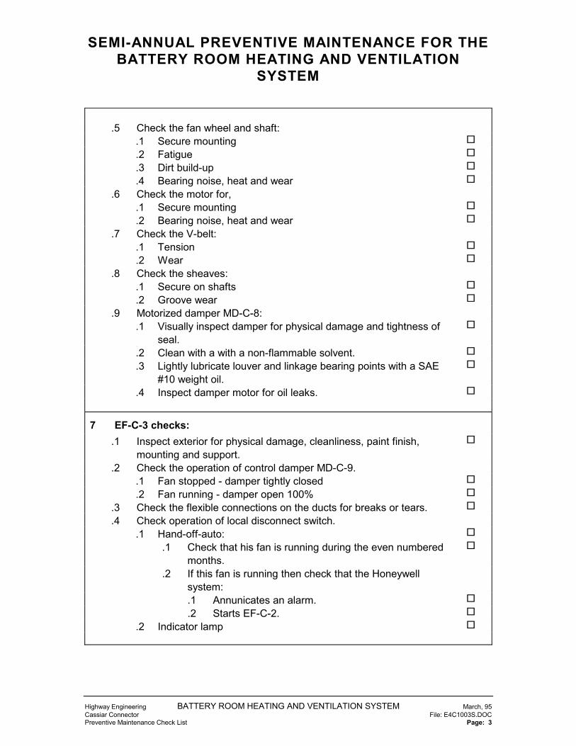
SEMI-ANNUAL PREVENTIVE MAINTENANCE FOR THEBATTERY ROOM HEATING AND VENTILATION
SYSTEM
Highway Engineering BATTERY ROOM HEATING AND VENTILATION SYSTEM March, 95Cassiar Connector File: E4C1003S.DOCPreventive Maintenance Check List Page: 3
.5 Check the fan wheel and shaft:.1 Secure mounting �
.2 Fatigue �
.3 Dirt build-up �
.4 Bearing noise, heat and wear �
.6 Check the motor for,.1 Secure mounting �
.2 Bearing noise, heat and wear �
.7 Check the V-belt:.1 Tension �
.2 Wear �
.8 Check the sheaves:.1 Secure on shafts �
.2 Groove wear �
.9 Motorized damper MD-C-8:.1 Visually inspect damper for physical damage and tightness of
seal.�
.2 Clean with a with a non-flammable solvent. �
.3 Lightly lubricate louver and linkage bearing points with a SAE#10 weight oil.
�
.4 Inspect damper motor for oil leaks. �
7 EF-C-3 checks:.1 Inspect exterior for physical damage, cleanliness, paint finish,
mounting and support.�
.2 Check the operation of control damper MD-C-9..1 Fan stopped - damper tightly closed �
.2 Fan running - damper open 100% �
.3 Check the flexible connections on the ducts for breaks or tears. �
.4 Check operation of local disconnect switch..1 Hand-off-auto: �
.1 Check that his fan is running during the even numberedmonths.
�
.2 If this fan is running then check that the Honeywellsystem:.1 Annunicates an alarm. �
.2 Starts EF-C-2. �
.2 Indicator lamp �

SEMI-ANNUAL PREVENTIVE MAINTENANCE FOR THEBATTERY ROOM HEATING AND VENTILATION
SYSTEM
Highway Engineering BATTERY ROOM HEATING AND VENTILATION SYSTEM March, 95Cassiar Connector File: E4C1003S.DOCPreventive Maintenance Check List Page: 4
.5 Check the fan wheel and shaft:.1 Secure mounting �
.2 Fatigue �
.3 Dirt build-up �
.4 Bearing noise, heat and wear �
.6 Check the motor for,.1 Secure mounting �
.2 Bearing noise, heat and wear �
.7 Check the V-belt:.1 Tension �
.2 Wear �
.8 Check the sheaves:.1 Secure on shafts �
.2 Groove wear �
.9 Motorized damper MD-C-9:.1 Visually inspect damper for physical damage and tightness of
seal.�
.2 Clean with a with a non-flammable solvent. �
.3 Lightly lubricate louver and linkage bearing points with a SAE#10 weight oil.
�
.4 Inspect damper motor for oil leaks. �
8 Final checks:.1 Ensure that breakers and disconnect switches have been returned
to their normal positions.�

SEMI-ANNUAL PREVENTIVE MAINTENANCE FOR THEEMERGENCY GENERATOR ROOM VENTILATION
SYSTEM
Highway Engineering EMERGENCY GENERATOR ROOM VENTILATION SYSTEM March, 95Cassiar Connector File: E4C1004S.DOCPreventive Maintenance Check List Page: 1
Item: �
1 General:.1 The maintenance listed in this table shall be done twice a year
immediately prior to the heating and cooling seasons..2 Notify tunnel operator 48 hours prior to maintenance..3 This PM shall not be performed during rush hours or emergencies.
2 Equipment:.1 Exhaust fan EF-C-1 is located on the south wall of the emergency
generator room and the control temperature sensor is located onthe north wall.
.2 The recirculation dampers and actuators are mounted in twobanks, one on each side of the engine radiator.
.3 The supply dampers and actuators are mounted on the southwall of the emergency generator room
.4 The relief dampers and actuators are mounted on the west wallof the emergency generator room.
.5 The local disconnect for the fan are located on the south wall.
3 Lock-out:.1 Refer to the Lock-out Section 103 of the Cassiar Tunnel Electrical
Maintenance Standards manual..2 Fan EF-C-1 is fed from panel J..3 The motorized damper actuators are fed from panel J.

SEMI-ANNUAL PREVENTIVE MAINTENANCE FOR THEEMERGENCY GENERATOR ROOM VENTILATION
SYSTEM
Highway Engineering EMERGENCY GENERATOR ROOM VENTILATION SYSTEM March, 95Cassiar Connector File: E4C1004S.DOCPreventive Maintenance Check List Page: 2
4 EF-C-1 checks:.1 Inspect exterior for physical damage, cleanliness, paint finish,
mounting and support.�
.2 Check the operation of EF-C-1 by heating the Honeywell sensorwith a little heat from a heat gun or by gently blowing into thesensor.
�
.3 Check the Honeywell alarm by switching EF-C-1 off at the localdisconnect while it is running under Honeywell control.
�
.4 Check the fan wheel:.1 Secure mounting �
.2 Fatigue �
.3 Dirt build-up �
.5 Check the motor for bearing noise, heat and wear. �
5 Louvers and actuators:.1 Visually inspect the recirculation, supply and relief dampers for
physical damage and tightness of seal.�
.2 Clean with a with a non-flammable solvent. �
.3 Lightly lubricate all louver and linkage bearing points with a SAE#10 weight oil.
�
.4 Inspect all damper motors for oil leaks. �
6 Final checks:.1 Ensure that breakers and disconnect switches have been returned
to their normal positions.�

SEMI-ANNUAL PREVENTIVE MAINTENANCE FOR THESUBSTATION VENTILATION SYSTEM
Highway Engineering SUBSTATION VENTILATION SYSTEM March, 95Cassiar Connector File: E4C1005S.DOCPreventive Maintenance Check List Page: 1
Item: �
1 General:.1 The maintenance listed in this table shall be done twice a year
immediately prior to the heating and cooling seasons..2 Notify tunnel operator 48 hours prior to maintenance..3 This PM shall not be performed during rush hours or emergencies.
2 Equipment:.1 Exhaust fans EF-C-5, EF-C-6 and EF-C-7 are located on the
north wall of the Substation and the control temperature sensor islocated on the north wall on the side of a Honeywell panel.
.2 The motorized control dampers MD-C-10, MD-C-11 and MD-C-12 and actuators are located on the inlet side of the exhaust fans.
.3 The MCC starters for the fans are located in MCC #2
.4 The inlet air louver and replaceable filters is located on the westwall of the substation.
3 Lock-out:.1 Refer to the Lock-out Section 103 of the Cassiar Tunnel Electrical
Maintenance Standards manual..2 Fans EF-C-5, EF-C-6 and EF-C-7 are fed from MCC starters in
MCC #2.

SEMI-ANNUAL PREVENTIVE MAINTENANCE FOR THESUBSTATION VENTILATION SYSTEM
Highway Engineering SUBSTATION VENTILATION SYSTEM March, 95Cassiar Connector File: E4C1005S.DOCPreventive Maintenance Check List Page: 2
4 EF-C-5 checks:.1 Inspect exterior for physical damage, cleanliness, paint finish,
mounting and support.�
.2 Check the operation of EF-C-5 by heating the Honeywell sensorwith a little heat from a heat gun by gently blowing into the sensor.
�
.3 Check the sequential operation of this fan with the other fans.Increasing heat starts the next fan.
�
.4 Check the operation of control damper MD-C-10..1 Fan stopped - damper tightly closed �
.2 Fan running - damper open 100% �
.5 Check operation of the disconnect switch..1 Hand-off-auto �
.2 Check the Honeywell alarm while the fan is running underHoneywell control.
�
.3 Indicator lamp �
.6 Check the fan wheel:.1 Secure mounting �
.2 Fatigue �
.3 Dirt build-up �
.7 Check the motor for bearing noise, heat and wear. �
.8 Motorized damper MD-C-10:.1 Visually inspect damper for physical damage and tightness of
seal.�
.2 Clean with a with a non-flammable solvent. �
.3 Lightly lubricate louver and linkage bearing points with a SAE#10 weight oil.
�
.4 Inspect damper motor for oil leaks. �
5 EF-C-6 checks:.1 Inspect exterior for physical damage, cleanliness, paint finish,
mounting and support.�
.2 Check the operation of EF-C-6 by heating the Honeywell sensorwith a little heat from a heat gun by gently blowing into the sensor.
�
.3 Check the sequential operation of this fan with the other fans.Increasing heat starts the next fan.
�
.4 Check the operation of control damper MD-C-11..1 Fan stopped - damper tightly closed �
.2 Fan running - damper open 100% �

SEMI-ANNUAL PREVENTIVE MAINTENANCE FOR THESUBSTATION VENTILATION SYSTEM
Highway Engineering SUBSTATION VENTILATION SYSTEM March, 95Cassiar Connector File: E4C1005S.DOCPreventive Maintenance Check List Page: 3
.5 Check operation of the disconnect switch..1 Hand-off-auto �
.2 Check the Honeywell alarm while the fan is running underHoneywell control.
�
.3 Indicator lamp �
.6 Check the fan wheel:.1 Secure mounting �
.2 Fatigue �
.3 Dirt build-up �
.7 Check the motor for bearing noise, heat and wear. �
.8 Motorized damper MD-C-11:.1 Visually inspect damper for physical damage and tightness of
seal.�
.2 Clean with a with a non-flammable solvent. �
.3 Lightly lubricate louver and linkage bearing points with a SAE#10 weight oil.
�
.4 Inspect damper motor for oil leaks. �
6 EF-C-7 checks:.1 Inspect exterior for physical damage, cleanliness, paint finish,
mounting and support.�
.2 Check the operation of EF-C-7 by heating the Honeywell sensorwith a little heat from a heat gun by gently blowing into the sensor.
�
.3 Check the sequential operation of this fan with the other fans.Increasing heat starts the next fan.
�
.4 Check the operation of control damper MD-C-12..1 Fan stopped - damper tightly closed �
.2 Fan running - damper open 100% �
.5 Check operation of the disconnect switch..1 Hand-off-auto �
.2 Check the Honeywell alarm while the fan is running underHoneywell control.
�
.3 Indicator lamp �
.6 Check the fan wheel:.1 Secure mounting �
.2 Fatigue �
.3 Dirt build-up �
.7 Check the motor for bearing noise, heat and wear. �
.8 Motorized damper MD-C-12:

SEMI-ANNUAL PREVENTIVE MAINTENANCE FOR THESUBSTATION VENTILATION SYSTEM
Highway Engineering SUBSTATION VENTILATION SYSTEM March, 95Cassiar Connector File: E4C1005S.DOCPreventive Maintenance Check List Page: 4
.1 Visually inspect damper for physical damage and tightness ofseal.
�
.2 Clean with a with a non-flammable solvent. �
.3 Lightly lubricate louver and linkage bearing points with a SAE#10 weight oil.
�
.4 Inspect damper motor for oil leaks. �
7 Inlet Filters:.1 These filters are checked by the weekly patrol and change these if
required.�
8 Final checks:.1 Ensure that breakers and disconnect switches have been returned
to their normal positions.�

BI-WEEKLY PREVENTIVE MAINTENANCE FOR THEELECTRICAL PATROL
Highway Engineering ELECTRICAL PATROL March, 95Cassiar Connector File: E4C1201W.DOCPreventive Maintenance Check List Page: 1
Item: �
1 General:.1 The maintenance listed in this table shall be done once every
second week..2 This maintenance shall not be performed during rush hours or
emergencies.
2 Control Building:.1 Operators’ Control Room:
.1 Check operation of room lighting in the operators’ controlroom, kitchen and washroom.
�
.2 Check the operation of the ventilation fans in the kitchen andwashroom.
�
.3 Check the entries in the tunnel operators maintenance logand ensure that corrective maintenance has been scheduledfor outstanding electrical items.
�
.4 Honeywell Control System.1 Check for alarms on Honeywell PC with tunnel
operator.�
.2 Check the environmental display screen:.1 Outside Air Temperature Sensor �
.2 Anemometer �
.3 Wind Vane �
.3 Fire-fighters Panel.1 Insert and turn the key and visually inspect the
panel.�
.2 The “General Fire” lamp should be “off” �
.3 The “Hydro Failure” lamp should be “off” �
.4 The “Controller Failure” lamp should be “off” �
.5 The “Normal” lamp should be “on” �
.6 The “Fire S.B. Tube” lamp should be “off” �
.7 The “Fire N.B. Tube” lamp should be “off” �
.8 Press “Lamp Test” button to test lamps. �
.9 Return the key to the red box. �

BI-WEEKLY PREVENTIVE MAINTENANCE FOR THEELECTRICAL PATROL
Highway Engineering ELECTRICAL PATROL March, 95Cassiar Connector File: E4C1201W.DOCPreventive Maintenance Check List Page: 2
.4 Emergency Backup Panel.1 Unlock and open panel door. This will disable all
other control of the tunnel fans except the MCC -time delay relays and give control to this panel.
�
.2 Visually inspect the panel. �
.3 Press the panel buttons to run each fan pairforward.
�
.4 Check the status lights on Emergency BackupPanel.
�
.5 Check appropriate indicator lights on substationMCCs.
�
.6 Close and lock panel door. This will stop any fansand return control of the tunnel fans to theHoneywell.
�
.7 Check appropriate indicator lights on substationMCCs.
�
.8 Return the key to the red box. �
.4 Fire Alarm System.1 Fire Alarm Control Panel
.1 Check that the correct date is displayed on theLED display.
�
.2 Check that no trouble, supervisory or alarmmessages are present.
�
.2 Fire Alarm Annunciator Panel.1 Check that no trouble, supervisory or alarms are
present.�
.5 Lane Signal Controller.1 Use caution when testing the lamp controller. Do not
test during periods of high traffic flow.�
.2 Check the signal head lamp status: Select each of thethree states in turn and select note if any LEDs are notilluminated. This indicates a faulty signal head lamp.
�
.6 CCTV Cameras.1 Visually check the video image quality of each monitor. �
.2 Target area positioning:.1 Tunnel coverage �
.2 Emergency door coverage �
.3 Check pan, tilt and zoom operation of 2nd Narrowscamera.
�

BI-WEEKLY PREVENTIVE MAINTENANCE FOR THEELECTRICAL PATROL
Highway Engineering ELECTRICAL PATROL March, 95Cassiar Connector File: E4C1201W.DOCPreventive Maintenance Check List Page: 3
.7 Traffic Detection and Monitoring.1 Ask the tunnel operator if the unit has had an excessive
number of “phantom” stopped vehicles, if the answer isaffirmative then record for corrective maintenance.
�
.8 Air conditioning.1 Ask the tunnel operator if the unit appears to be
operating satisfactorily, if the answer is negative thenrecord for corrective maintenance.
�
.2 Corridor:.1 Check operation of corridor and radio room lighting . �
.2 Entrance Heating.1 Ask the tunnel operator if the unit appears to be
operating satisfactorily, if the answer is negative thenrecord for corrective maintenance.
�
.3 Battery Room:.1 Check operation of room lighting. �
.2 Ensure that the battery room and equipment are clean andfree of loose objects.
�
.3 Uninterruptable Power System.1 Check the Digital Display Screen on the UPS cabinet
door. The message will read “Normal Operation”indicating that the UPS is currently OK.
�
.2 Visually inspect Batteries -for swelling, leaks, dirt andforeign objects.
�
.4 Battery Room Heating and Ventilation.1 Ensure that the supply fan is running and that there is
no abnormal noise or vibration.�
.4 Generator Room:.1 Check operation of room lighting. �
.2 Emergency Generator.1 Ensure that the generator room and equipment are
clean and free of loose objects.�
.2 Check that the engine block heater is working. Theengine block should be warm to the touch.
�
.3 Check battery charging voltage on panel meter. Thisshould be greater than 25.5 volts.
�
.4 Check status of generator alarm indication lights ondetached panel. No alarms should be present. Presslamp test.
�
.5 Check the status of the generator room electrical panel( dark blue ): main breaker ‘charged’ and ‘closed’
�

BI-WEEKLY PREVENTIVE MAINTENANCE FOR THEELECTRICAL PATROL
Highway Engineering ELECTRICAL PATROL March, 95Cassiar Connector File: E4C1201W.DOCPreventive Maintenance Check List Page: 4
.5 Mechanical Room:.1 Check operation of room lighting in the mechanical and
storage rooms.�
.2 Check the pumps for abnormal noise or vibration if they areoperating.
�
.3 Check the piping and equipment for leaks. �
.6 Substation:.1 Check operation of room lighting. �
.2 Ventilation.1 Check that room temperature is not hot. �
.1 Check filters for cleanliness and change if necessary. �
.3 Electrical.1 Low Voltage Switch Gear
.1 Check the status of the disconnect and transferswitches:.1 sub-station secondary main breaker ( light
blue ) : ‘charged’ and ‘closed’�
.2 emergency bypass (dark blue): ‘open ’and‘locked’
�
.3 emergency breaker (dark blue): ‘open’,‘unlocked’ and ‘charged’
�
.4 normal breaker(dark blue): ‘closed’,‘unlocked’ and ‘charged’,
�
.5 normal bypass (dark blue): ‘open’ and‘locked’
�
.2 Inspect the MCC Switch Gear and Panel Boards forexternal damage, burned-out indicator lamps andtripped condition.
�
.7 Building exterior:.1 Check operation of the perimeter lighting �
3 Northbound and Southbound Tunnels:.1 Visually check the following equipment for exterior physical
damage and abnormal operation:.1 Carbon monoxide cabinets �
.2 Tunnel fans �
.3 Lane Signal Heads �
.4 Tunnel Lighting �
.5 CCTV Cameras �
.6 Emergency Cabinets �
.2 Check the operation of each tunnel emergency telephone. �

BI-WEEKLY PREVENTIVE MAINTENANCE FOR THEELECTRICAL PATROL
Highway Engineering ELECTRICAL PATROL March, 95Cassiar Connector File: E4C1201W.DOCPreventive Maintenance Check List Page: 5
4 Final checks:.1 Lock all doors and return keys. �
.2 Ensure that no Honeywell alarms are present. �