price $125.00 december, 2019 practices for cross bore risk...price $125.00 december, 2019 cross bore...
TRANSCRIPT

Price $125.00 December, 2019
Cross Bore Safety Association, is a not for profit 501(c)3 organization. Complimentary copies in digital PDF format are available to document authors and contributors, the organizations they represent, and those organizations referenced within the document, and their members. Governmental and educational organizations are allowed complimentary copies. www.crossboresafety.org • [email protected]

Page 1 of 88
Leading Practices for Cross Bore Risk Reduction.docx Copyright© 2019 Cross Bore Safety Association, Inc. www.crossboresafety.org All Rights Reserved.
Leading Practices for Cross Bore Risk Reduction Focus of Gas Lines Intersecting Sewers
Date: December 18, 2019 This Leading Practice was prepared through the consensus of industry representatives from utilities, construction companies, manufacturers, industry associations, inspection companies and service providers. Special recognition and appreciation are given to Mark Bruce, Jeff Graham, Pat Gribbon, Susan Harmon, Michael Kemper, John Mickelson, Joe Purtell, Annmarie Robertson, Christina Sames, Greg Scoby, Tim Thorsen, Levi Valdois and Mark Wallbom for their significant contribution to the preparation and review of the Leading Practices for Cross Bore Risk Reduction. Preface: A cross bore1 is an intersection of an existing underground utility or underground structure by a second utility resulting in direct contact between the transactions of the utilities that compromises the integrity of either utility or underground structure1, see Figure 1. Cross bores are commonly caused from:
• Unknown existence or location of facilities • No verification of the location and the depth of known facilities • Unknown path of underground utility • Use of trenchless technology installation methods
Cross bores1 have been recognized as a high-level risk to utilities system integrity. This risk was recognized in 1976, when the U.S. Department of Transportation investigation2 concluded that a death and four injuries were attributed to an intersection of gas distribution line and a sanitary sewer. In a 1999 ruling the Kentucky Public Service Commission received a complaint3 that directional drilling used during gas line installations intersected three of the fifty-six potential sanitary sewer lateral intersections. The Commission ruled visual inspections were required of the gas utility “to determine if any damage to either facility has occurred”. This ruling3, as well as two explosions in the late 1990’s that were the result of cross bores, resulted in contractors and utilities starting to look for ways to minimize the risk of cross bores from past (legacy) and new installations. Reported cross bore explosions, though infrequent, have been indicated (though formally constrained by non- disclosure settlements) to have costs of up to thirty million
Figure 1: House sewer lateral with cross bore

Page 2 of 88
Leading Practices for Cross Bore Risk Reduction.docx Copyright© 2019 Cross Bore Safety Association, Inc. www.crossboresafety.org All Rights Reserved.
dollars per single incident. This document encourages the use of tools, processes and quality control methods to ensure high quality results. High confidence cross bore risk mitigation practices should be an expectation and can be achieved with thoughtful planning and verifiable leading practices. The Cross Bore Safety Association was founded in 2008 to specifically focus on ways to reduce the risk from cross bores, subsequent to preliminary efforts of a NASTT4 Cross Bore committee. To better address the need for guidance, the Leading Practices for Cross Bore Risk Reduction is the summation of the best contemporary knowledge regarding cross bore mitigation. It is recommended that one read the full contents of this document to provide the best context for the more specific recommendations. Legal Notice Neither the organization, it’s members nor the contributors make any warranty or representation, expressed or implied with respect to the use, accuracy, completeness of the herein contained information nor assumes any liability with respect to the use or damages resulting from the use of the document, recommended apparatus, methods or processes. The use or reliance on this document is solely at that party’s risk. State, federal and local employee safety requirements which are applicable for the work type contemplated for cross bore risk reduction are not included in this document. Appreciation and recognition is given for the essential support of the past and present CBSA Board of Directors: Mr. Lance Andrews, Atmos Energy
Mr. Bernie Bernhard, Association of Equipment Manufacturers
Mr. Mark Bruce, Cross Bore Safety Assoc. President, Hydromax USA and Legal Liability Chairman
Mr. Tyler Boyles, Union Gas and Stakeholder Awareness Chairman
Mr. Glen Carter, Pacific Gas &Electric
Mr. Clifford Clark, Enbridge Gas Distribution
Mr. Mark Chepke, Columbia Gas Virginia
Mr. William Etzler, Aqua Indiana
Ms. Susan Harmon, Charles Machine Works
Mr. Walt Kelly, Walt Kelly Enterprises
Mr. Michael Kemper, Mears Group, Inc. of Quanta Services, Inc. and Construction Committee
Chairman
Mr. Mark Knight, University of Waterloo
Mr. Steve Lacy, Hydromax USA
Mr. Brian Matson, Digital Control, Inc. and Legacy Installation Chairman
Mr. Michael McGivery, Enbridge Gas Distribution and Stakeholder Awareness Chairman

Page 3 of 88
Leading Practices for Cross Bore Risk Reduction.docx Copyright© 2019 Cross Bore Safety Association, Inc. www.crossboresafety.org All Rights Reserved.
Mr. Joe Purtell, Cues, Inc. and Data Management Chairman
Ms. Annmarie Robertson, PHMSA and Leading Practices Steering Committee
Ms. Christina Sames, American Gas Association
Mr. James Schofield, Enbridge Gas Distribution
Mr. Greg Scoby, Cross Bore Consultants, Inc. and Leading Practices Steering Committee
Chairman
Mr. Mark Wallbom, Hydromax USA and Leading Practices Steering Committee and Risk Analysis
Committee Chairman

Page 4 of 88
Leading Practices for Cross Bore Risk Reduction.docx Copyright© 2019 Cross Bore Safety Association, Inc. www.crossboresafety.org All Rights Reserved.
Table of Contents: Preface 1 Legal Notice 2 Appreciation and Recognition of Board of Directors 2 Table of Contents 4 Executive Summary 5 Use of Document 6
Cross Bore Background Information: Chapter 1 History of Cross Bores 7
Chapter 2 Financial and Social Costs 9
Chapter 3 Current Practice Gaps 10
Chapter 4 Installation Equipment at Risk of Creating Cross Bores 10
Chapter 5 Results of Cross Bores and the Timeline 11
Chapter 6 Stakeholders’ Opportunities to Minimize Cross Bore Risk and Impacts 12
Chapter 7 Regulatory Safety Improvement Opportunities 17
Chapter 8 Regulatory Rate Support 18
Chapter 9 Sources of Cross Bore Information 19
Technical Recommendations for Cross Bore Risk Elimination
Chapter 10 Cross Bore Risk Reduction Goals 20
Chapter 11 Outline of Risk Reduction Project Tasks 20
Chapter 12 Legacy Risk Determination 20
Chapter 13 New Construction Risk Reduction 26
Chapter 14 Data Preservation, Accessibility and Security 35
Chapter 15 Data Use Across the Enterprise 37
Chapter 16 Quality Control and Quality Assurance 37
Chapter 17 Project Metrics 47
Chapter 18 Public Outreach 47
Chapter 19 Access to Sewer Systems and Public Right-of-way and Private Property 50
Chapter 20 Scoping for Cross Bore Risk Reduction Inspections 51
Chapter 21 New Construction Inspections 54
Chapter 22 Robotic Mainline and Launched Lateral CCTV Inspections 56
Chapter 23 Manual Push CCTV Inspections 61
Chapter 24 Vacuum Excavation/Daylighting Used for Cross Bore Risk Reduction 66
Chapter 25 Pull Back Camera Use 67
Chapter 26 Ground Penetrating Radar Use 68
Chapter 27 Other Emerging Tools for Future Consideration 69
Chapter 28 Locating and Tracking Field Work 70

Page 5 of 88
Leading Practices for Cross Bore Risk Reduction.docx Copyright© 2019 Cross Bore Safety Association, Inc. www.crossboresafety.org All Rights Reserved.
Chapter 29 Proximity Determinations 71
Chapter 30 Cleanout Installation 72
Chapter 31 Owner/Occupant Notifications 72
Chapter 32 Records Retention 75
Summary 76
References 76
Definitions 77
Credits for Graphics 78
Appendix A: Publications 79
Appendix B: Examples for Notices, Door Hangers and Letters 82
Executive Summary The natural gas industry has requested a guidance document to help minimize the creation of unplanned intersections of one utility with another (cross bore1) and eliminate legacy cross bores that have been installed in past construction activities.
One of the most serious cross bore risks is the presence of natural gas distribution lines installed through sewer pipes. Several natural gas utilities system integrity evaluations have identified cross bores as their highest risk.
Awareness of the risk has gradually spread through most of the gas distribution industry, but effective ways to mitigate the risk are not standardized. New projects are being implemented without historical perspective and good sources of information. This document is intended to share the leading practices for cross bore risk reduction. Cross bore risk reduction began in the mid-late 1990’s using improved process focus and then technologies based upon visual verification in the 2000’s. Updated camera systems are still the primary tool of preference for most cross bore inspection projects. Thorough, deliberate construction practices also reduce the creation of new cross bores. As experience has been gained, better practices using more capable tools and processes have been developed. Many tools, techniques and processes are needed to successfully complete an effective risk mitigation program. More recently, sophisticated risk models coupled with prioritization modeling are proving effective for decreasing risk faster and with more efficiency. Proven practices are providing utilities efficient high confidence results. Low confidence practices can leave a false sense of security and result in incorrect cross bore determinations. Industry leaders now recognized low confidence risk mitigation practices are no bargain, impede their reputation and allow risk to remain for the gas distribution industry. Inadequate confidence of the processes may require costly re-work. A well-founded cross bore risk mitigation effort benefits from using all the resources that are available to achieve the best results and highest confidence. To achieve high confidence, collection of data should be designed to allow robust quality control processes including GPS

Page 6 of 88
Leading Practices for Cross Bore Risk Reduction.docx Copyright© 2019 Cross Bore Safety Association, Inc. www.crossboresafety.org All Rights Reserved.
tracked locations of cameras traversing through sewers compared to the gas line locations, separate office review of inspection videos, and office personnel determining the final status vs. relying on of the field determination. Quality control elements should use appropriate statistical analysis to monitor processes to ensure high confidence results are achieved. A well-designed program consists of many elements. Cost effective, strong public outreach efforts to inform and educate customers, utility workers and drain cleaners of cross bore risk should be included. Drain cleaner support and cross bore risk information to reduce impacts from drain cleaning cutting tool are important components of any cross bore mitigation program. A risk reduction program should be used with local knowledge specific to the area to allow for variations of installation methods, geology and building practices. Stakeholders are cautioned to use existing information that can be fully trusted. Project plans and requirements should evolve as new data is gained and opportunities for improvement are identified. A long-term implementation strategy for installation processes which eliminate new cross bore risk and for identifying and removing all legacy cross bores is appropriate. Cross bores have been created over a period of decades. Reasonable timelines focused on reducing the highest exposure should be allowed for planning, implementation and refinement to achieve a high confidence risk mitigation program result. Use of Document The intent of this document is to provide a more detailed instructive guidance than is currently available, but not to be prescriptive. Its purpose is to serve as a resource for natural gas contractors, subcontractors, utility owners and service providers in reducing the risk of utility damage associated with trenchless technology being performed by any entity in the vicinity of an
underground utility. The target users are those managing or developing cross bore risk reduction efforts and all stakeholders involved in cross bore risk reduction.
A decision to implement any part in this document requires evaluation of specific knowledge, local conditions and consequences of cross bores by the user. The final goal is to prevent future cross bores as well as identify existing, legacy cross bore locations for removal. Most cross bores can be avoided with the implementation of standardized detailed practices and a robust QAQC program to ensure compliance. While natural gas distribution cross bores pose the most significant risk and are accordingly, this document’s primary focus; this information can be of use for all utilities and trenchless construction. Damage prevention and utility safety processes are mandated at various federal, state and local levels. Regulations are broad in scope and leave implementation processes undefined. Actions taken to minimize the creation and impact of existing cross bores are the responsibility of the utility owner, the installer, cross bore inspection service providers and those who may encounter cross bores.

Page 7 of 88
Leading Practices for Cross Bore Risk Reduction.docx Copyright© 2019 Cross Bore Safety Association, Inc. www.crossboresafety.org All Rights Reserved.
CROSS BORE BACKGROUND INFORMATION 1. History and Background
of Cross Bores In the March, 2016 issue of AGA’s American Gas magazine there is a good article titled “Industry Update: Cross Bore Prevention” which provides a summary overview of the history of cross bores. Cross bores1 were first identified at the federal level in the November 12, 1976 National Transportation Safety Board report2, see Figure 2. The incident resulted in two deaths and 4 additional injuries. Then in the mid-late 1990’s two major natural gas pipeline installation contractors recognized the importance of addressing cross bores gas explosions which occurred as a result of natural gas lines installed in sewers. Cross bores (see Figure 1, 2 and 3a, 3b and 4) that result in fires or explosions are infrequent but can have catastrophic impact. The primary problem typically occurs when a homeowner has a sewer back up and a drain cleaning tool is inserted into the lateral to clear the blockage. These cleaning tools often times have the ability to cut through the wall of the gas line. Should that occur, gas could flow freely into the home through the sewer or porous trench backfill. If an ignition source is present, the gas-air mixture could ignite when the oxygen to gas ratio reaches a combustible mixture. Fire and catastrophic explosions can result, with damage, injury or death.
a. Trenchless installation practices have the highest potential to create a cross bore. Trenchless installation methods used in either new construction or replacement projects include percussion pneumatic piercing tools (impact moles, missiles, gophers, hole hogs, bullets), boring, tunneling/microtunneling, pipe ramming, pipe jacking, pipe driving, horizontal directional drilling (HDD), boring/auger boring, plowing, planting and any other method for the installation of pipe with minimal disruption and minimal excavation of the ground surface. It is essentially everything other than open cut/open trench installation.
b. Trenchless installation methods do not allow visual observation of the installation.
Figure 2: NTSB 1976 Report
Figure 3a: Cross bores of Sewer.

Page 8 of 88
Leading Practices for Cross Bore Risk Reduction.docx Copyright© 2019 Cross Bore Safety Association, Inc. www.crossboresafety.org All Rights Reserved.
c. Class 2 cross bores5 are intersections of two utilities by another utility, allowing transmission of product between the two intersected utilities. An existing sewer and gas line can be penetrated by a trenchless installation of a third utility allowing gas to flow into a sewer and resulting in an explosion of a structure. See Figure 4. Explosions have also occurred when an existing gas line was intersected by a trenchless installation allowing migration of the released gas through porous backfill and into the structure.
d. Gas distribution pipelines are particularly susceptible to catastrophic results from cross bores. Smaller gas lines have relatively thin walls and are frequently made of plastic materials that are more easily damaged than larger pipelines that are thicker and/or made of steel. Also, the smaller distribution gas lines are frequently located at structures where sewer laterals are prevalent and more likely to encounter drain cleaning activities.
e. Gas distribution pipelines are often identified as the highest utility risk category from cross bores. The ratio of gas lines intersecting lateral sewers as compared to intersecting mainline sewers is in the range of 4:1 in some systems and in others approach a 1:1 ratio (source CBSA). Intersections in mainline sanitary sewers are less frequent due to the depth of collection sewers and the frequent (but not always) relatively higher elevation of gas pipeline installation.
f. Storm drain sewers typically have catch basins at street level. Storm sewers can be pierced with drain cleaning tools; however, the gas can vent to the surface and is less likely to reach an explosive concentration. Compared to sanitary sewer lateral cross bores, storm sewer lateral cross bores are generally lower risk. Combined storm and sanitary sewers should be assumed to be connected directly to the interior of structures and have higher risk than storm sewers alone.
g. Large transmission lines have greater wall thickness and are often made of steel or iron resulting in a lower likelihood of penetration from a drain cleaning tool.
Figure 4: Class 2 Cross Bore. Communications HDD intersects sewer lateral then gas line
Figure 5: Results of Class 2 Cross Bore Explosion, Texas
Figure 3b: Cross bores of Sewer.

Page 9 of 88
Leading Practices for Cross Bore Risk Reduction.docx Copyright© 2019 Cross Bore Safety Association, Inc. www.crossboresafety.org All Rights Reserved.
Transmission lines are not often identified as high risk for resulting catastrophic damage from cross bores and less likely to be associated with drain cleaner activity.
h. There have been instances where a plastic gas line has penetrated a cast iron sewer and over time the plastic line settled into the jagged edges of the sewer without external activities. One resulted in a house explosion from the gas leak into the sewer lateral which allowed the migration of gas into the structure.
i. Common Ground Alliance DIRT reporting for 20166 identified natural gas as representing 46.2% of the total $1.5 billion excavation damage societal costs for all utilities. Total number of all types of excavation damages to all facilities in the CGA 2017 DIRT reporting is estimated at 439,0007. The report includes Canada and the U.S. DIRT has come to recognize the importance of the potential problems associated with cross bores. Their newest reporting format now enables damage as a result of cross bores to be documented.
j. Prior to the keeping of specific records of past cross bore damage, information may be gleaned from damage repair records. Repair descriptions that included sewer components are useful in assessing if damage was from cross bores. This information can assist in determining the quantity of historical cross bores discovered, often by drain cleaners.
k. Nationally, existing and repaired cross bores of sewers by gas lines is estimated at approximately four tenths (0.4) per main mile has been estimated by CBSA based upon numerous, but far from comprehensive, industry informal reports. There are approximately 1.3 million miles of natural gas mainlines. A large targeted large cross bore project had over 2.3 cross bores per mile, 430 per nearly 200 miles. The range of cross bores per mile is highly variable from system to system.
l. Numerous documents and articles regarding cross bore risk have been published. Please note some suggestions for additional information listed in Chapter 9 and in the References section of this document.
2. Financial and Social Costs Damages to utilities, including those from cross bores, are now capable of being more accurately reported using DIRT. Actual damage costs to physical assets are easily monetized. Other costs are harder to determine and might not be reported. Injury and death financial impacts are often undetermined and some convincingly argue that they are incalculable. Other significant impacts of cross bores to personal and company reputations are beyond the typical cost calculations of damage. For occurrences with catastrophic results, the impact is not only the immediate and local, but also national.
3. Current Practice Gaps Opportunities for improvement are first generated by identifying the need. The following are some identified practice gaps that should be addressed.
a. New and previously installed (legacy) gas lines require validation to ensure trenchless installations are cross bore free. This is a central to reducing risk from cross bores.

Page 10 of 88
Leading Practices for Cross Bore Risk Reduction.docx Copyright© 2019 Cross Bore Safety Association, Inc. www.crossboresafety.org All Rights Reserved.
b. Using vacuum excavation to daylight existing utilities is effective when the existing utility locations are known. However, when unknown, a vacuum excavate/daylight does not occur.
c. The utility industry’s current practices for minimizing the creation of new cross bores and eliminating impacts from existing cross bores lack standardization.
d. Many of the processes that have been used lack effective quality control resulting in the inability to validate and verify, resulting in a false sense of security.
e. Plastic pipe installations may exceed the locatable life of the traceable conductors that are installed. This may lead to long term difficulty in locating utilities.
f. New and replacement construction requires identification of all utilities in the installation zone per regulatory damage prevention procedures. However, storm and sanitary are typically not provided by the sewer operators nor the sewer lateral owners. State regulators have typically not required the location of gravity mainline sewers nor sewer laterals but should change regulations to require sewer location.
g. Sewer drain cleaners are frequently unaware of cross bore risks. Additionally, they are typically not adequately trained and do not have written processes dealing with potential cross bores in sewers.
h. Coordination of efforts with regulators, utility operators, contractors and the public needs to be maximized. Some examples include:
i. Local sewer regulations can require the inspection of sewers prior to final sale of a property;
ii. Municipal sewer authorities can require the installation of exterior cleanouts next to the foundation of structures which will facilitate easy maintenance and inspection for cross bores.
iii. To protect their facilities and provide support for safety to the public, sewer operators can elect to provide location of sewers or mapping even when regulations do not require locates.
iv. Sewer operators may assist by locating private sewers or providing available lateral mapping when available.
i. Utility regulators are progressing to more fully support legacy cross bore elimination programs. Inadequate recovery of costs or long delays can contribute to the slower elimination of cross bore risk.
4. Installation Equipment at Risk of Creating Cross Bores Trenchless technology (see list of equipment and methods in 1. a. above) has resulted in the creation of many cross bores. However, its use has numerous social and economic advantages and benefits to the industry and, ultimately, for the public. Some advantages follow:
a. Less impact to sensitive surface areas such as wetlands b. Reduced social impact and other disruptions to the community c. Reduced road and landscape repairs and replacements d. Monetarily, it may be a less expensive solution for a specific project

Page 11 of 88
Leading Practices for Cross Bore Risk Reduction.docx Copyright© 2019 Cross Bore Safety Association, Inc. www.crossboresafety.org All Rights Reserved.
5. Results of Cross Bores and the Timeline The risk of a cross bore is typically highest after installation/replacement and before post-camera inspection takes place. However, some risk remains as not all cross bores may be identified until a blockage occurs. Root growth over time may also create a blockage requiring a drain cleaner to be called out. Cross bores have the potential of creating problems almost immediately, but frequently the effects are delayed until a sewer drain cleaning action occurs or after new construction when utilities are not yet connected and used by a new structure owner. A discussion of the problems and timeline of these impacts is provided below to illustrate opportunities to reduce risk.
a. Possible Immediate and Near Immediate Results i. During drilling, operators of trenchless technology sometimes note the
often accurate yet unreliable feel of a void. They should be aware that reaming tools may pose additional potential for damage and report this feeling to management for investigation.
ii. Mud pressure may be lost and recognized, if drilling with drilling muds. This should be reported to management and investigated.
iii. When an intersected utility is damaged and recognized, repairs should be made immediately.
iv. The damage can cause immediate injury or death to the construction crew, structure occupants and nearby public. An example could be if a fiber optic line is being installed with a trenchless method, the drill first intersects a lateral sewer, then intersects a gas line, causing a rupture of the gas pipeline (See Figure 4 & 5). The pressurized gas flows into the sewer or surrounding porous trench backfill and ultimately into an adjacent structure causing fire or explosion when the gas-air ratio reaches combustive limits with an ignition source. This could even occur after a few hours of migration of gas through backfill.
v. Newly installed cross bores of sewers can obstruct the flow of sewers and manifest themselves as blockages soon after installation. It is important to warn and notify structure occupants of the risk of drain cleaning after trenchless installations and before construction has been verified as having created no cross bore risk.
1) Sewer drain cleaners have discovered many cross bores during drain cleaning which extended to the exterior of the structure.
2) Cutting tools of drain cleaning machines can easily cut plastic pipe, natural gas lines, water lines, and so on.
3) Drain cleaning tools can disrupt communication cables and cause grounding of electric services (possible electrocution with contact).
b. Possible Long Term Results If damage to existing utilities is not readily apparent, the impact may not be known until a much later time.
i. Cross bore risk is not removed until discovered, compromising the integrity of the utilities.

Page 12 of 88
Leading Practices for Cross Bore Risk Reduction.docx Copyright© 2019 Cross Bore Safety Association, Inc. www.crossboresafety.org All Rights Reserved.
ii. Damage and injury effects remain unrecognized at the time of occurrence, leaving a latent exposure.
iii. Cost of repairs to an existing facility is deferred, possibly not at the expense of the creator of the damage.
iv. Other activities in the vicinity can have unexpected impacts on the compromised and structurally weakened utilities.
v. Drain cleaners accessing a cross bored sewer line can come into contact with the intersecting utility. The rotating cutting tools can pierce a gas line causing injury or death to occupants and those in the immediate vicinity if escaping gas is ignited.
c. Additional impacts i. Damage to the reputation of company creating the cross bore.
ii. Impact to the utility company being viewed as less safe to their public. iii. Temporary moratoriums on the use of trenchless technology. These have
been imposed by local jurisdictions after incidents. The impact of the loss of trenchless techniques is disruptive and potentially expensive for utility operators, contractors and manufacturers of trenchless equipment.
iv. Additional regulatory scrutiny to utilities and installers. v. Negative impact on rate setting regulators.
vi. Increased insurance premiums or difficulty obtaining insurance. vii. Personal individual moral burden for not acting appropriately to prevent
injury, damage or death.
6. Stakeholders’ Opportunities to Minimize Cross Bore Risk and Impacts The following information is provided to identify ways major stakeholders can help reduce new cross bores and eliminate existing, legacy cross bores.
a. Owner/Operators of utilities i. Identify and mark accurate locations of its buried utility infrastructure in
accordance with state and local requirements and owner/operator procedures.
ii. Contract only with suppliers who use leading practices. iii. Provide contract language and budgets that support leading practices.
Suggestions for contact provisions/requirements include: 1) For construction contractors, provide line items to cover the costs
of all leading practices. 2) For camera inspections for cross bores:
a) Verify that the video shows the entire circumference of the pipe with potential risk.
b) Verify that the traverse of the camera is beyond the risk of the gas line intersection using mapping of both the gas line and the sewer inspection traverse.
c) Camera and inspect all branches of the sewer that may be at risk.

Page 13 of 88
Leading Practices for Cross Bore Risk Reduction.docx Copyright© 2019 Cross Bore Safety Association, Inc. www.crossboresafety.org All Rights Reserved.
d) Request alternate inspection methods to be used when prior results are incomplete and not of high confidence.
e) Use separate verifiable quality assurance and quality control processes for all inspection activities to assure high confidence results.
3) For vacuum excavations, verify the location and depth by reviewing the image or video to confirm the findings. a) Ensure all at-risk utilities have been considered including
unmarked gravity sewers. i.) Risk can remain when there are more utilities to avoid
than realized. ii.) All utilities locations, including sewers, must be known
in advance for directing vacuum excavations effectively.
iii.) Notify the utility owner if the marked facilities do not correspond to the excavated locations.
b) Compare the location with the mapped installation to verify inspections are beyond the area of risk.
c) Request alternate methods of inspection to be used when results are incomplete or not of high confidence.
d) Use separate, verifiable QAQC processes. iv. After construction, place cleanout warning tags to warn plumbers that a
recent gas installation/replacement was done. v. Use modeling to create legacy inspection programs to direct inspect
locations identified as having cross bore risk or where cross bore risk is uncertain
1) Use historical information to determine the initial Risk Model a) Incorporate high occupancy structures and difficult to
evacuate structures with appropriate risk levels b) Use GIS8 or similar tools to apply risk to adjacent properties.
For example, it is possible for a property to have no risk from trenchless construction directly, but to be impacted from other nearby structures if the adjacent property were to have a catastrophic incident from a gas cross bore.
c) Include all high confidence data, but discount or discard low confidence data. (Low confidence means that there is little faith at all in the information. Highest confidence would be that there is no doubt at all. Confidence levels should be determined as appropriate for the needs. See Chapter 13 for more information.)
2) Use Prioritization Models to determine inspection scheduling to remove the most risk with a defined level of effort (cost and time).

Page 14 of 88
Leading Practices for Cross Bore Risk Reduction.docx Copyright© 2019 Cross Bore Safety Association, Inc. www.crossboresafety.org All Rights Reserved.
a) The model should place a higher priority for high consequence structures (high occupancy, difficult to evacuate) such as:
i.) Hospitals ii.) Nursing homes
iii.) Schools iv.) Public gathering places v.) Homes that typically have shallow sewer services near
the same elevation of the new gas utility, including tiered homes
vi.) And similar structures b) Include the effort and cost of risk mitigation as compared to
the expected risk reduction to be achieved i.) Successful prioritization should result in higher risk
reduction from early program work as compared to later program work. As the high risk is reduced early in the program the relative effort for subsequent risk reduction will be higher.
ii.) Successful prioritization would not be on a basis of number of properties inspected, but on the amount of modeled risk reduction.
3) Validate and rerun the risk model and the prioritization model to ensure the predictive model is meeting expectations.
4) Adjust the risk and prioritization models periodically to accommodate new or additional data developed during the program.
5) Include goals for metrics 6) Include appropriate QAQC process for high confidence results.
vi. With all relevant stakeholders, provide systems to share all data across the enterprise for higher economic benefits and safer operations for stakeholders, to include:
1) Data obtained during inspection programs, including mapping of utilities and construction activities, should be captured in a manner that is useful to the utility’s current and future needs.
2) GIS and other data structures which are useful to provide spatial asset information of assets for improved: a) Maintenance b) Design c) Planning d) Installation e) Leak, corrosion and other safety surveys f) 811 dig ticket requirements g) Program management h) Public safety
Page 15 of 88
Leading Practices for Cross Bore Risk Reduction.docx Copyright© 2019 Cross Bore Safety Association, Inc. www.crossboresafety.org All Rights Reserved.
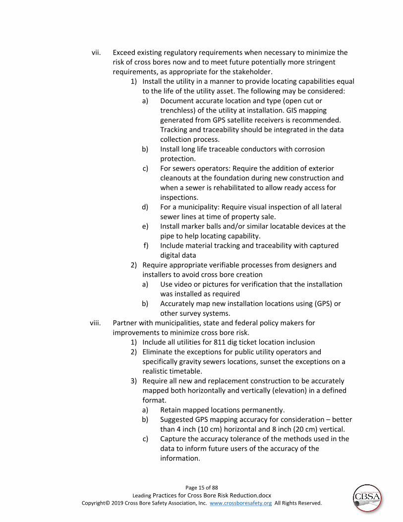
vii. Exceed existing regulatory requirements when necessary to minimize the risk of cross bores now and to meet future potentially more stringent requirements, as appropriate for the stakeholder.
1) Install the utility in a manner to provide locating capabilities equal to the life of the utility asset. The following may be considered: a) Document accurate location and type (open cut or
trenchless) of the utility at installation. GIS mapping generated from GPS satellite receivers is recommended. Tracking and traceability should be integrated in the data collection process.
b) Install long life traceable conductors with corrosion protection.
c) For sewers operators: Require the addition of exterior cleanouts at the foundation during new construction and when a sewer is rehabilitated to allow ready access for inspections.
d) For a municipality: Require visual inspection of all lateral sewer lines at time of property sale.
e) Install marker balls and/or similar locatable devices at the pipe to help locating capability.
f) Include material tracking and traceability with captured digital data
2) Require appropriate verifiable processes from designers and installers to avoid cross bore creation a) Use video or pictures for verification that the installation
was installed as required b) Accurately map new installation locations using (GPS) or
other survey systems. viii. Partner with municipalities, state and federal policy makers for
improvements to minimize cross bore risk. 1) Include all utilities for 811 dig ticket location inclusion 2) Eliminate the exceptions for public utility operators and
specifically gravity sewers locations, sunset the exceptions on a realistic timetable.
3) Require all new and replacement construction to be accurately mapped both horizontally and vertically (elevation) in a defined format. a) Retain mapped locations permanently. b) Suggested GPS mapping accuracy for consideration – better
than 4 inch (10 cm) horizontal and 8 inch (20 cm) vertical. c) Capture the accuracy tolerance of the methods used in the
data to inform future users of the accuracy of the information.

Page 16 of 88
Leading Practices for Cross Bore Risk Reduction.docx Copyright© 2019 Cross Bore Safety Association, Inc. www.crossboresafety.org All Rights Reserved.
d) Include installed materials information when mapping newly installed utilities.
e) Include specific company and individual installer information when mapping newly installed utilities.
4) Allow use of accurately mapped utilities with GIS systems as an option to onsite locate paint markings to encourage higher use of 811 dig ticket systems than currently available a) Rapid digital response18 will eliminate perceived timeline
impediments b) Lower cost
b. Installers (contractor and owner/operator crews) of new or replacement asset when trenchless technology is used.
i. Ensure all leading practice safety and cross bore risk reduction requirements are followed.
ii. Do not accept work when leading practices to prevent and/or verify cross bores are not in the Owners/Operator’s specifications.
iii. Work with Owners/Operators and industry groups to promote leading damage prevention practices like CGA and Gold Shovel Standard.
c. Drain cleaners i. Inform all technicians of the risk of cross bores to themselves and the
property’s occupants. ii. Identify low risk techniques such as only using cutters on exterior sewers after
the line has been cleared of cross bore risk. 1) Use the gas distribution utilities special support and education
programs for assisting drain cleaners to avoid cross bore piercing 2) Report cross bores when found.
iii. Do not accept work when leading practices to prevent and/or verify cross bores are not in the Owners/Operator’s specifications.
iv. Work with utility and industry associations to promote leading damage prevention practices
d. Camera Service Providers and Technicians I. If pre-construction camera inspections are not utilized, the risk of damage
is greater. The pre-construction camera locates the sewer utilities to provide the excavator information needed to safely use trenchless technology without causing a cross bore or other damage. It not only provides location and depth verification of the sewer lines before construction begins, it increases production levels and, most importantly, minimizes the exposure of unknowingly damaging a utility line during installation then leaving it damaged until the post camera is completed at some later date, and risking a cross bore in the meantime.17
II. If pre-construction camera inspections are not followed by post-construction camera inspections, there will remain a chance a cross bore

Page 17 of 88
Leading Practices for Cross Bore Risk Reduction.docx Copyright© 2019 Cross Bore Safety Association, Inc. www.crossboresafety.org All Rights Reserved.
was created during construction, but not identified. The purpose of the post inspection CCTV is the assurance that a cross bore or damage has not happened. This method is evidence that the sewer line is in the same condition as it was before the installation. Equipment failures and human error have caused cross bore even after a pre-inspection was complete.
7. Regulatory Safety Improvement Opportunities
Most states and provinces in Canada regulate the safety of pipelines and other utilities and, in most cases, have accepted enforcement of some or all of the federal requirements. They often also provide regulatory guidance for the management of the Call Before You Dig 811 system and set utility rates. Individual regulations differ between states, providing unique variation. State and federal regulators and legislators should require improvements to construction and inspection practices to minimize cross bore risk unless the industry does so itself. The following elements should be considered:
a. Cooperate to regionalize or nationalize safety efforts to provide more sharing and standardization of leading practices.
i. Utilities with operations in several states and contractors working for utilities with operations in several states are challenged by the variations in regulatory requirements.
ii. More consistent industry wide processes will help cross bore risk reduction efforts as well as many other damage prevention benefits.
b. Ability to locate utilities is compromised by corrosion of locating conductors used for location non-conductive utility materials. States are encouraged to require as-builts of construction which are accurately geo-referenced and stored within GIS systems, providing long-term effective locations of assets6.
i. This coincides with newly developed tracking and traceability regulations proposed for gas distribution systems.
ii. Accurate GIS mapping of utilities can be used with other field devices to supplement or replace onsite manual locates using GIS mapping.
iii. This should be encouraged and allowed for new construction and replacement of non-georeferenced as-built drawings.
iv. Suitable timelines should be allowed to phase in this requirement to allow matching it with tracking and traceability implementation.
c. Include all utilities for 811 dig ticket locations. i. Minimize the exceptions for gravity sewers locations
ii. Sunset the exceptions on a realistic timetable d. Require all new and replacement construction to be accurately mapped both
horizontally and vertically. i. Include installed materials information when mapping newly installed
utilities. ii. Include specific company and individual installer information when
mapping newly installed/replaced utilities.

Page 18 of 88
Leading Practices for Cross Bore Risk Reduction.docx Copyright© 2019 Cross Bore Safety Association, Inc. www.crossboresafety.org All Rights Reserved.
iii. Grade changes over time can occur. Vertical measurements of locations should be elevation based.
e. Allow use of accurately mapped utilities using GIS based as-built drawings as an option to traditional painted site markings/locates to speed locates and provide better information to excavators as explored in pages 6, 7 and 8 of the CGA 2016 DIRT6. GIS mapping with boundary limits can be pushed to mobile and desktop devices digitally for rapid locates onsite. The benefits include:
i. Speed of results can encourage higher use of 811 dig ticket systems currently available.
ii. Enables rapid GIS mapping response in minutes vs. manual onsite locates which takes days. This will eliminate a perceived impediment to use.
1) Residents and other maintenance technicians will be encouraged to use the 811 Call Before You Dig systems.
2) 811 systems can have higher usage and more success in preventing damage.
iii. Cost for locates may be lower due to shorter wait times by contractors and residents.
iv. Definitive record of mapping is maintained for dispute resolution. v. The problem of excavation or other activities which remove markings
can be reduced with GIS processes. vi. Cross bore risk and other excavation damage risk can be reduced.
f. Current 811 dig ticket marking requirements have time limits for the marking of dig tickets. If the time to perform locates expires due to locator personnel shortage or otherwise, regulations may allow construction to begin. This results in higher potential for damages, whether trenchless or otherwise. See 2016 Dirt Report recommendations:
i. Providing locates prior to construction should be required and construction should not be permitted without locates, except for emergencies.
ii. GIS mapping based locates reduces the cost impact to re-locate after expiration.
8. Regulatory Rate Support It is recognized that cost recovery that is delayed or uncertain has been an impediment to reducing risk from cross bores. Costs of inspections, damage prevention and DIMP9 requirements related to new construction are normally included in state regulatory authorized recovery of costs for gas utilities. Senior utility team members should consider taking the opportunity to educate regulators and encourage support for cross bore risk reduction through regulatory improvements and rate recovery for associated costs. New construction and inspections related to the new construction frequently have more rapid cost recovery mechanisms. However, legacy inspection costs are often classified as

Page 19 of 88
Leading Practices for Cross Bore Risk Reduction.docx Copyright© 2019 Cross Bore Safety Association, Inc. www.crossboresafety.org All Rights Reserved.
O&M and in many instances are incurred with delay and without assurance the costs will be recovered fully. To allow for increased safety from cross bore risk, it is recommended that regulators and legislators with senior utility management develop cost recovery mechanisms which recognize legacy cross bore inspections as if these costs would have been part of the construction contemporaneously, allowing for rapid recovery.
9. Sources of Cross Bore Information a. Associations
i. American Gas Association, AGA ii. American Petroleum Institute, API
iii. American Public Gas Association, APGA iv. American Public Works Association, APWA v. Association of Energy Service Professionals, AESP
vi. Cross Bore Safety Association, CBSA vii. Canadian Gas Association
viii. Common Ground Alliance ix. Distribution Contractors Association, DCA x. Engineering & Utility Contractors Association, EUCA
xi. Gas Technology Institute, GTI xii. International Society for Trenchless Technology, ISTT
xiii. Midwest Energy Association xiv. National Association of Public Safety Representatives, NAPSR xv. National Association of Sewer Service Contractors, NASSCO
xvi. National League of Cities, NLC xvii. National Underground Contractors Association, NUCA
xviii. National Underground Contractors Locating Association, NULCA xix. North American Society for Trenchless Technology, NASSTT xx. Office of Pipeline Safety, OPS
xxi. Operations Technology Development, OTD xxii. Pipeline and Hazardous Materials Safety Administration, PHMSA
xxiii. Power & Communication Contractors Association, PCCA b. Educational/Research Institutions Involved in Trenchless
i. Arizona State University, ASU ii. Louisiana Tech University, Trenchless Technology Center, TTC
iii. Operations Technology Development, OTD iv. University of Texas, Arlington, UTA v. University of Waterloo, Waterloo, Canada
Technical Recommendations for Cross Bore Risk Elimination 10. Cross Bore Risk Reduction Goals
These technical recommendations provide a framework for high confidence cross bore risk reduction, verifiable processes, metrics for evaluation and opportunities to share

Page 20 of 88
Leading Practices for Cross Bore Risk Reduction.docx Copyright© 2019 Cross Bore Safety Association, Inc. www.crossboresafety.org All Rights Reserved.
information within organizations and throughout the industry. The expected results are increased safety, enhanced damage prevention, increased external and internal customer satisfaction and potentially better economic returns. The enterprise value of installers, inspection providers and utilities can be better protected.
11. Outline of Risk Reduction Project Tasks The following list includes elements that should be considered for determining cross bore risk and development of a program to mitigate the risk.
a. Evaluate potential exposure, determine if systemic risk is evident. Include regulatory requirements for integrity and safety.
i. Determine existing legacy risk(s) from prior construction ii. Determine new construction risk(s)
iii. Determine replacement construction risk(s) b. If risk is found, consider the following elements:
i. Identify separate budget impacts of new and replacement construction and legacy risk reduction.
ii. Validate economics of differing alternatives. iii. Propose and obtain budget approval. iv. Determine internal staff. v. Create Project Management Team.
vi. Identify opportunities to coordinate with all departments, enterprise-wide, for use of collected data.
vii. Develop project requirements and RFP. viii. Select cross bore risk reduction services provider, internal staff and/or
construction process changes. ix. Utilize Risk Models and Prioritization Models for identifying and
prioritizing work. x. Monitor metrics.
xi. Adjust Risk Model and Prioritization Model as new data is collected. xii. Modify project requirements as opportunities for improvement occur.
xiii. Continue to repeat steps h through m, above. xiv. Share data for multiple benefits across the enterprise.
12. Legacy Risk Determination
Legacy cross bore risk is the exposure to a cross bore created in post construction, existing installations. In reality, all legacy cross bore mitigation efforts can be considered time delayed construction work. This topic is critical to cross bore risk reduction. In some states rate recovery for legacy cross bores have been tied to a long timeline recovery mechanism which impedes risk reduction of legacy cross bores. The cut-off between legacy and new/replacement construction risk is a topic of discussion that often includes input from accounting and legal departments for perspective to General Accepted Accounting Practices (GAAP) and state regulations for cost recovery. Allowing for adequate time to complete high confidence inspections related to new construction is the

Page 21 of 88
Leading Practices for Cross Bore Risk Reduction.docx Copyright© 2019 Cross Bore Safety Association, Inc. www.crossboresafety.org All Rights Reserved.
minimum threshold of time that should be allowed to distinguish legacy from new construction. This time should recognize repeated attempts using differing tools and private owner permissions which may have impeded the initial inspection efforts. Subsequent sections of this document illustrate the time for access to structures can be substantial. However, trenchless installations not constructed with leading practices and with high confidence that there were no cross bores created are generally considered a legacy cross bore risk.
The consideration for developing legacy cross bore risk reduction efforts should include evaluation of the following elements:
a. Use historical information available and rate the confidence level in the accuracy of the information. Conservative estimates should be used when there is uncertainty.
b. Include current staff memories and other written records. c. Examples of making preliminary work prioritization for legacy projects include:
i. Determine the date when first use of trenchless installations began. ii. Identify replacement projects (vs. new construction installations) since
they generally take place in areas with existing utilities where there is more opportunity for cross bores.
iii. Determine pipe materials and sizes compatible with trenchless installations. For example, larger diameter lines may have less risk than smaller lines since the increased wall thickness usually associated with metal pipes may better resist the piercing damage that can occur from drain cleaner activities.
iv. Determine pipe material not used with trenchless installations. v. Determine the remaining life of the pipe.
vi. Determine if cast iron, ductile iron or steel pipe was used. Cast iron or steel pipe is less easily cut with drain cleaner root cutters than is plastics pipe of equal thickness. Note: Cast iron, ductile iron and steel are often prioritized for replacement due to corrosion concerns and, therefore, often have a limited remaining useful life, resulting in a lower prioritization.
vii. Determine main and service line operating pressures. Higher pressures have greater capability to release gas and quickly enter a structure at the explosive limits of natural gas.
viii. Proximity to high consequence structures (see 6. iv., 2). ix. Joint trench installations may be considered as not being a trenchless
installation when the gas line is inserted in a conduit installed by open cut methods. Often this process has been used in large subdivisions and, if evaluated, large areas may be deemed risk-free. If no cross bores can be determined readily and with high confidence in early evaluations, the budget planning can be more accurate with substantially lower overall budgets and project costs.

Page 22 of 88
Leading Practices for Cross Bore Risk Reduction.docx Copyright© 2019 Cross Bore Safety Association, Inc. www.crossboresafety.org All Rights Reserved.
x. Open fields and open parks that may have low density use may be evaluated lower risk and lower priority. However, if such an area has experienced trenchless construction, proximity to nearby higher consequence structures should be evaluated for risk effects.
1) Include special focus on trenchless free parcels that may be impacted by the radius of explosion from adjacent parcels.
2) Debris and impact from a structure exploding as a result a cross bore has the potential to travel. An initial determination radius of at least 200 feet may be appropriate, for adjacent parcel impact, subject to review by the program management team.
xi. Determine for each knowledge category and differentiate between high and low confidence information. The decision should be weighed and the results of the decisions recorded.
xii. Search for other sources of information. For instance, it has been found effective to infer historical cross bore quantities and build a record of repaired cross bores from past invoice records where repair items included sewer, plumber or sewer type of materials. These types of items would indicate a sewer line was intersected, creating a cross bore.
1) Meet with plumbers and sewer drain cleaners and determine if they have found cross bores that may not have been reported in the current system.
2) A leading practice is that the utility adds a category of damages found as cross bore vs. other types of damages for easier data searches and reporting.
xiii. Use geo-referencing or similar GIS tools to associate nearby structure risk factor to the pipeline cross bore risk factors. A parcel (property) which does not have a risk of a trenchless installed cross bore directly on it could still be at risk of collateral damage from nearby parcels that have cross bore risk. An example may be a school that has no trenchless cross bore installed on the property, but the bus pickup zone is close enough to be impacted by an adjacent property that could have a catastrophic explosion from a gas cross bore intersection. A beginning criterion for determining collateral damage may initially be considered at approximately 200 feet (60 meters) for natural gas distribution pipelines since the radius debris from a catastrophic explosion of a gas filled structure is substantial. These impact areas should be determined by the program management team.
xiv. Look for data that is not directly apparent such as a construction superintendent or installation contractor with a higher cross bore incident rate than the others.
xv. Depth of installation has been a frequent identifier of potential for cross bores. For example, a structure on a slab may have higher elevation for sewers and other utilities thus making it more likely to

Page 23 of 88
Leading Practices for Cross Bore Risk Reduction.docx Copyright© 2019 Cross Bore Safety Association, Inc. www.crossboresafety.org All Rights Reserved.
have a conflict with other vertically similar utilities. In colder climates water and sewers may typically be deeper than in warmer climates.
1) However, even in cold climates caution should be taken that lines don’t have less cover as they get closer to the served structures, for example, tiered yards.
2) Utilities serving structures on low lying beaches have been found to have a higher potential for conflicts with each other since installations in high water tables are expensive at deeper depths driving all utilities to the upper elevations.
xvi. Obtain sewer mapping from sewer system operators to help identify elevations of sewers for general comparison with gas installations. Note: This is often limited to mainline sewer information with a small percentage of sewer operators have maps of sewer laterals to structures. Accuracy of main line sewer mapping can be partially affirmed by getting manhole depths.
xvii. Save the risk model criteria, as it will typically be updated later and change the risk analysis. Each change of risk analysis methodology and parameters should be archived in a defined data structure to enhance the next generation of managers’ understanding of the past results. Use a Risk Model for the data assembled. GIS data structure allows for association of distance between structures and utilities to be included in the model’s algorithms.
xviii. Mature models for cross bores have been developed and are available to be customized to each utility’s risk factors. Guidance for risk modeling can be found in the CBSA document “Risk Management for High Confidence Results for Cross Bore Programs” 17.
xix. Big-data risk models have also been created to evaluate risk associated with legacy cross bores. These proprietary models can provide better correlation between predictions and actual cross bores discovered than manual algorithms and should be considered. These types of models are effective when using large volumes of data. Figure 6 provides an example of such results.
xx. Test the model’s result on a defined interval. Adjust or discard factors if they are not proven valid. Update the model for improvement.

Page 24 of 88
Leading Practices for Cross Bore Risk Reduction.docx Copyright© 2019 Cross Bore Safety Association, Inc. www.crossboresafety.org All Rights Reserved.
xxi. Prioritization models are an extension of a risk model. Projects benefit from using the risk model together with prioritization factors. Prioritization factors include budget limitations and timing of the program budget. Adding factors for the material life of the existing utility, known obsolescence, for the planned capital improvement (replacement) budget or other types upgrades that affect the life of the existing utility will drive the prioritization results. Shorter life would typically lower the risk.
xxii. Combining both legacy and new/replacement construction inspections is frequently more cost effective and results in greater risk reduction for a given amount of physical and financial resources. This is frequently found to be effective in sewer inspections for cross bores where a main sewer line is traversed for a single structure that has a new utility installed and the area has been modeled for legacy risk reductions. Commentary: A cross bore program typically will take several months to get organized. Initial steps may be to begin by inspecting schools, hospitals and nursing homes.
d. Once cross bore mitigation for new installations, replacement installations or legacy risk) is determined to require risk reduction, the following elements should be considered:
Figure 6: Risk modeling visualization based on parcel boundaries and using color coding

Page 25 of 88
Leading Practices for Cross Bore Risk Reduction.docx Copyright© 2019 Cross Bore Safety Association, Inc. www.crossboresafety.org All Rights Reserved.
i. Legacy risk reduction, new construction, and replacement installation initiatives are best addressed as three separate yet related initiatives for thoroughness and efficiency.
ii. Identify project management leaders and team members. iii. Balance legacy inspections with new and replacement construction risk
reduction programs. 1) Focus on the relative risks regardless of other priorities or
efficiencies. 2) Determine the extent and location of the new construction and
replacement plans. 3) Evaluate the planned replacement timeline with a legacy
inspection plan. 4) Prioritize where efficiencies can be achieved by combining
inspection work for new/replacement construction with legacy inspections without affecting the very high risk evaluated parcel inspections (schools, hospitals, nursing facilities and so on).
iv. Determine the appropriate field and other processes, as discussed in subsequent Chapters.
v. Define QAQC processes. vi. Determine the desired timeline.
vii. Determine the cost parameters. 1) For budget planning and approval needs, it is recommended to
use initial estimates from service providers and industry peer’s experience customized to the conditions and the service areas at risk.
2) Determine budget including internal requirements and personnel. 3) Gain budget approval and timelines for implementation.
viii. Determine the requirements of regulations 1) PHMSA requirements including Distribution Integrity
Management Plan9 (DIMP) for natural gas distribution pipelines which includes system integrity considerations
2) State regulations 3) Local regulations
ix. Determine data structure and data storage requirements x. Select metrics, reporting frequency and tolerance allowed
xi. Determine confidence levels. xii. Decide the reporting which meets the project management team needs
xiii. Determine customer outreach goals and processes to maintain high customer satisfaction.
xiv. Include call center processes to respond to cross bore mitigation efforts and provide general information about the project.
xv. Create specifications for soliciting providers. xvi. Bid for services and select inspection service provider.
xvii. Revise program as more information is learned.

Page 26 of 88
Leading Practices for Cross Bore Risk Reduction.docx Copyright© 2019 Cross Bore Safety Association, Inc. www.crossboresafety.org All Rights Reserved.
xviii. Who will be responsible and organize the repair activity? 1) Track repair status 2) Permit and inspection requirements
13. New and Replacement Construction Risk Reduction New construction and replacement projects should include verifiable, high confidence construction and inspection processes which eliminate the risk of creating new cross bores. Since replacement installations have a higher risk of creating a cross bore, this paper primarily addresses replacement installations. For new installations the same steps should be considered and then tailored to each specific new construction project since there are often situations when certain steps are applicable for replacement installations but not for new installations; for example, when it has been confirmed that there are no existing utilities in the area. Again, new construction and replacement installations are best addressed as two separate yet related processes in order to achieve maximum thoroughness and efficiency. Utility and installation contractors’ liability will be reduced when the work includes high confidence inspection programs. Cross bore risk reduction methods should be integrated in the utility project requirements for construction. Commentary: It is suggested that contractors consider avoid working on projects where safe
Figure 7: Basic Legacy Cross Bore Inspection Process Chart

Page 27 of 88
Leading Practices for Cross Bore Risk Reduction.docx Copyright© 2019 Cross Bore Safety Association, Inc. www.crossboresafety.org All Rights Reserved.
practices related to cross bore risk reduction are not in the policy nor are leading practices required by the utility in the work scope and provided for in the cost structure of the installation specifications. Commentary: Use of high confidence, post-construction camera CCTV (Closed Circuit Television) inspection processes are considered the most effective method to verify that cross bores have not been created. However, the importance of the pre-construction CCTV is to avoid damage. The pre-construction camera locates the sewer utilities to provide the contractor the information needed to maximize the safe use of trenchless technology without causing a cross bore or other damage. It not only provides location and depth verification of the sewer lines before construction begins, it increases production levels and, most importantly, minimizes the exposure of unknowingly damaging a utility line during installation and then leaving it damaged until the post camera is completed at some later date, and risking a cross bore in the meantime.17
a. Planning for new and replacement installation risk reduction should include: a. Many regulations suggest exposing the existing known utility crossings during
construction as a means of minimizing risk. Vacuum excavations are often used to expose crossings. However, since gravity sewers are not typically located per 811 requirements, pre-construction sewer locating and post-construction cross bore CCTV inspections have been used to mitigate cross bore risk to ensure they have not been created.
i. The decision to televise sewers before or after construction or both should be made by the management team in coordination with the utility risk evaluation team.
ii. Pre-construction locates of gravity sewers can minimize risk since the contractor then knows where the existing sewer is, but this does not verify that the installer did not accidentally intersect the sewer. In some regards, if this is the only technique used, it can provide a false sense of success.
iii. Daylighting, with good verification processes, can confirm all crossing utilities do not intersect will eliminate risk if all utility locations are known in advance.
iv. Combining post construction inspections with a good notification system to inform occupants to call the utility until their property is cleared of risk has proven to be effective and efficient. Risk remains until the post construction inspection process using leading practices is complete.
v. An advantage of post-construction inspections of sewer pipes is that inadvertently installed cross bores can be found. The results can be considered higher confidence, when good program processes are utilized.
vi. The leading practice is to include the use of both pre- and post-camera inspections. Alternatively, pre-construction CCTV inspections followed by vacuum excavation/daylighting, performed as recommended within

Page 28 of 88
Leading Practices for Cross Bore Risk Reduction.docx Copyright© 2019 Cross Bore Safety Association, Inc. www.crossboresafety.org All Rights Reserved.
this document and as specified in Section 24.j. with all processes to be verifiable and with 100% quality control, may be considered suitable to determine that a cross bore has not been created. In such cases the following minimum requirements are recommended.
1) The vacuum excavation shall remain open until after the reaming processes (if any) are completed and the pull back of new utility at the crossing is installed to allow visual determination that a cross bore was not created. Photos or video shall be taken post construction but prior to backfilling.
2) The post installation photo, video and location shall show the separation of the existing and the new utility meet installation requirements at the correct location and demonstrate that neither a cross bore nor damage has been created.
b. If the quality control process does verify the requirements of Section 24. j. and this section are met, post construction CCTV inspections shall be performed to determine that no cross bore has been created. Previously determined no or low risk properties, where new construction is imminent, should be reclassified to an at-risk status. The timing of the change should be far enough in advance to allow for all variability of construction planning that could accelerated the work.
i. High confidence tracking of new trenchless installations is required to alert the post-construction inspections team to begin work.
ii. Processes that are accurate, digital and rapidly update database information are recommended.
c. Since the risk of a cross bore is typically highest soon after installation occurs (see 5. above) and before post-camera inspection takes place, it is important to coordinate post-installation verification inspections closely after construction, but allowing reasonable timelines, as discussed below.
d. The leading practice is to wait to introduce gas into a new installation until it has been inspected for cross bores. Even though delaying the energizing of newly installed lines may be inconvenient and impractical in many circumstances, not doing so is a hurried process which is likely to yield lower confidence results.
i. The timeline to coordinate access to structures, if needed to complete inspections before gas up, may be longer than ideal. Careful planning is required.
ii. Quality control processes should have appropriate time to review the work.
e. When using trenchless construction, it is important to notify structure occupants that trenchless construction has the potential to intersect with their sewer. This could cause damage, injury or death to occupants and those nearby if the newly created cross bore is compromised by drain cleaning. This information, transmitted by a door hanger, letter and/or website, should strongly recommend the structure occupant contact the utility prior to any sewer drain cleaning that is beyond the foundation. Prior notification of inspections is normally a requirement

Page 29 of 88
Leading Practices for Cross Bore Risk Reduction.docx Copyright© 2019 Cross Bore Safety Association, Inc. www.crossboresafety.org All Rights Reserved.
of the risk reduction program. This allows for better public satisfaction as well as informs and notifies occupants of the process.
i. Sewer cross bores manifest themselves in a manner that more sewer drains are found with impeded flow and blockages in relation to time elapsed. Roots can grow into the damaged pipe and debris can collect until a blockage is created.
ii. The utility should provide first response or approved service providers to assist with drain cleaners by locating the gas line risk.
iii. The utility should have a call center to coordinate the utility first response in event drain cleaning is required to accept calls from occupants.
iv. Call Before You Clear information should be accessible through webpages or other methods.
v. In some cases, websites combined with mobile apps have been developed for utilities to be used by plumbers and drain cleaners to provide lists of at-risk for cross bore properties. This may be coupled with incentives.
f. When inspections are unsuccessful from the mainline sewer, and when exterior cleanouts are not available, permission for access to the property for manual push inspections and other methods will be required with scheduled appointments.
i. The notification process can be simple or extensive. Scheduling appointments may be via phone and letter. Plans and metrics should allow adequate timelines to allow for multiple contact attempts to obtain access permissions.
ii. All notification and appointment processes need to be tracked. iii. Sewer laterals may cross property lines. The adjacent property may not
have gas service and a drain cleaning activity of the adjacent property can create risk to the adjacent and other connected structures. It is important to obtain access to such adjacent properties when needed.
g. In some cases, utilities have elected to discontinue service if adequate safety inspections cannot be arranged with the occupant or the owner.
h. Processes should be continually reviewed for opportunities for improvement. i. After the inspection processes are completed and indicated that a parcel has no
cross bore risk, if even one cross bore is found metrics should include a thorough review of the project processes.
i. Limits of errors should be determined and recorded in metric goals. ii. It is recommended to statistically evaluate the acceptable limit by the
utility risk evaluation team based upon the injury, loss of life, cost of the risk reduction, company reputation and regulatory requirements.
j. The program management team should consider these elements: i. Consider coordination of new/replacement construction risk reduction
with legacy risk reduction where efficiencies can be achieved.

Page 30 of 88
Leading Practices for Cross Bore Risk Reduction.docx Copyright© 2019 Cross Bore Safety Association, Inc. www.crossboresafety.org All Rights Reserved.
ii. Determine the appropriate processes to use, as discussed later in this and in subsequent chapters.
iii. Determine budget including internal requirements and personnel. iv. Gain budget approval and timelines for implementation v. Identify project management leader and team members
vi. Define the field processes to be used vii. Define QAQC processes
viii. Determine data structure and data storage requirements ix. Select metrics, reporting frequency and tolerance allowed x. Determine confidence levels.
xi. Determine the reporting requirements which meets the project management team needs
xii. Determine customer outreach goals and processes to maintain high customer satisfaction
xiii. Include call center processes to respond to cross bore mitigation efforts and provide general information of the project
xiv. Create specifications for soliciting providers xv. Bid for services and select inspection service provider.
xvi. Revise program as more information is learned. xvii. Determine which sewer operators are involved within their service
territory and initiate relationships. k. The elements of Figure 7 are similar to the primary the process elements to
consider for new construction recommendations. Development of a detailed process flow chart will provide benefits to the project management team to ensure work expectations are complete, including QAQC and data integration considerations.
b. Installation activities for cross bore risk reduction for new and replacement of gas installations should consider:
i. New and replacement installations are addressed together here. However, replacement installations have a higher risk of creating a cross bore since more existing utilities exist in built our areas, so this section deals with replacement installations. For new installations adjustments may be made based upon variations from these the same steps tailored to each specific new construction project. New construction and replacement installations are best addressed as two separate yet related processes in order to achieve maximum thoroughness and efficiency.
ii. Ensure all leading practice safety requirements are followed including Job Site Briefings that investigate potential cross bores in existing installations and establishing a tolerance/safety zone with a minimum clearance of 2 foot/0.6 meters horizontal and 1 foot/0.3 meters vertical based on sewer and natural gas mark-outs or as otherwise locally regulated. The leading practice when installing/replacing distribution lines is full camera use - both pre-construction and post-construction.
1) Pre-construction team information – for CCTV inspections: The purpose of the pre-construction CCTV (Closed Circuit Television) is to minimize damage. During the pre-construction phase, camera crews should

Page 31 of 88
Leading Practices for Cross Bore Risk Reduction.docx Copyright© 2019 Cross Bore Safety Association, Inc. www.crossboresafety.org All Rights Reserved.
perform all sewer locates within the construction zone where trenchless technology will be performed. If pre-construction camera inspections are not utilized, the risk of damage is greater. The pre-construction camera inspection locates the sewer utilities to provide the excavator information needed to safely use trenchless technology without causing a cross bore or other damage. It not only provides location and depth verification of the sewer lines before construction begins, it increases construction production levels and, most importantly, minimizes the exposure of unknowingly damaging a utility line during installation. When this damage does occur, this risk remains until the post -construction inspections are complete. Listed below are pre-construction steps for the camera crew.
a) The camera crew must be provided notification of the work area to be inspected. This may be through GIS mapping or other means in advance or the work area may be determined once on site. If in advance, drawings should be provided showing the extent of the inspection area desired. If the area is determined on site, both the camera crew and construction supervisor should verify their understanding and sign off on the drawing prints or in another manner.
b) Construction damage prevention requires knowing the location of all utilities, including gravity sewers prior to construction. Sewer efforts are not always required under 811 regulations and may require additional efforts to locate.
c) Sewer prints from the city are reviewed, if available, and the accuracy is verified.
d) Often where cross bore inspection programs are in progress, the utility’s service provider for these inspections will have access to sewer mapping and may even have additional mapping information.
e) Commentary: Inspections have shown that some mainline sewers have very bad pipe conditions which make the cost of inspection much higher than normal. Such conditions are rare but include very high debris levels in sewers (which is costly to remove and dispose), numerous collapses of the pipe, sections of reduced diameter or small diameter collection lines which are difficult to inspect. Options can include:
i.) Request the sewer operator to clean the mainline sewer.
ii.) Consider using open trench rather than trenchless installation methods in the affected area.

Page 32 of 88
Leading Practices for Cross Bore Risk Reduction.docx Copyright© 2019 Cross Bore Safety Association, Inc. www.crossboresafety.org All Rights Reserved.
f) When the determination of the inspection work area is made on site, the camera crew meets with the installation representative for the extent of the project to ensure mutual understanding of what is to be done and what needs to be located. (Leading Practice: a physical walk through with drawings described in Section 13.2.b.i.)
g) The camera crew inspects all of the relevant sewer lines within the entire trenchless path. Sewers from adjacent properties may cross into the construction area. The inspection area limits for the CCTV inspections should include such risk.
h) All sewer taps, wyes and tees are accounted for to ensure multiple taps and branched sewers at any address are inspected.
i) Sanitary and storm sewers should be considered for risk. j) If a property cannot be inspected from the main, an
attempt to push-camera the property should be made. If the owner is not present, a door hangar explaining the work and requesting a follow up call should be left in plain sight. (See samples in Figure 8 and Appendix B.)
k) Due to restrictions, roots, offset joints, overall length of line, debris, water sags and grease, not all CCTV efforts will result in a high confidence video. Inadequate view of the sewer pipe circumference may result in not identifying a branch. This results in the inability to verify the sewer’s location in the area with complete confidence. Locating sondes and other methods may not be effective in all cases due to EM interference. Sewer inspection personnel
Figure 8: Door hangers for new construction and cross bore risk.

Page 33 of 88
Leading Practices for Cross Bore Risk Reduction.docx Copyright© 2019 Cross Bore Safety Association, Inc. www.crossboresafety.org All Rights Reserved.
should be cautioned to not make assumptions that are not verifiable.
l) The camera inspection service provider is responsible for documenting its work. This may be with markings on site as well as manual or digitally created records of the work to illustrate where the sewer utility is located for each property based on what was inspected. An example of a manual entry traditional sewer inspection card for pre-construction on page 87 and a digital example on page 88.
m) Once the camera inspection is completed, the CCTV inspection service provider shall provide the record of inspections in the manner required by the Owner.
2) Construction team information – with CCTV pre- and post inspections: a) Before installation begins, the installer shall verify that the
One-Call processes are completed and current. All other additional safety and damage prevention processes of the installer are required to be followed.
b) It is highly recommended that the camera representative and the construction supervisor walk the work area together, sharing all relevant information and documentation including the installation path. Any remaining areas which require inspections should be documented by both parties. Note: the Leading Practice is to not rely on paint or flags as they can be moved or fade; verifiable records are superior.
c) After the pre-job walk, the installation crews install the utility lines based on what the camera crews located. If a utility was not able to be located, the recommended installation is open cut.
d) If a sewer tap was found at the main which cannot be inspected, the affected installation is recommended to be open cut. Main line inspections should verify that additional laterals to that structure do not exist.
e) Installer should follow all Owner and industry Leading Practices during construction.
f) All sewer videos and inspection records should be verified for location, full traverse as needed, completeness as to location depth and have 100% separate video review, see Section 14 and see Sewer Inspection Card examples on Page 87 and 88.
g) The installation crew records the installation method (including type and trenchless method used), location and depth of installation, see Sewer Inspection Card examples on Page 87 and 88.

Page 34 of 88
Leading Practices for Cross Bore Risk Reduction.docx Copyright© 2019 Cross Bore Safety Association, Inc. www.crossboresafety.org All Rights Reserved.
h) This documentation is then used to guide the inspection crews to determine the extent of post construction inspections and within QAQC processes to ensure a cross bore was not created.
i) As appropriate to avoid damages, vacuum excavation/daylighting should be performed according to the practices of this document, damage prevention regulations and to the Owner’s and installer’s additional requirements.
c. Post construction CCTV inspection considerations: i. The purpose of the post inspection CCTV is the assurance that a cross bore or other
damage has not occurred. This method provides evidence that the sewer line is in the same condition as it was before the installation. Incomplete and inaccurate pre-construction inspections, equipment failures, inadequate construction processes and human error can result in a cross bore even after a pre-inspection. If pre-construction camera inspections are not followed by post-construction camera inspections, there will remain a chance a cross bore was created during construction, but not identified. Because of the potential for these errors it is recommended that post camera inspection is performed in all cases.
1) It is recommended to record the video and the traverse using GPS. It is also recommended to take the location of the gas installation. This information is reviewed in QAQC processes to verify that the visibility was adequate, the extent of the CCTV traverse extended beyond the gas risk, and the inspection was performed at the correct location/s.
2) Use of mainline CCTV, push cameras, vacuum excavation, cleanout installations and proximity determinations may be required to verify that no cross bore exists.
3) If the status of the inspection project shall be recorded and determinations of cross bore risk shall be subsequent to the QAQC processes have been performed, see Section 16.
4) It is recommended the sewer owner be notified when pipe conditions are found which can lead to an impending likelihood of backing up. Pre and post- construction videos are useful to determine change in sewer condition during the construction.
5) Each change of status of the inspection process should be recorded and made available to the gas utility and project personnel. The utility should change from “cleared of cross bore” status to “at risk” status if new construction with trenchless technology is planned.
6) It is recommended that information be provided to the property owner/occupant to inform them of the progress and completion of work.
ii. Installers and inspection providers should be guided by verifiable information. Making assumptions are inappropriate and dangerous. Some illustrates of common assumptions are:

Page 35 of 88
Leading Practices for Cross Bore Risk Reduction.docx Copyright© 2019 Cross Bore Safety Association, Inc. www.crossboresafety.org All Rights Reserved.
1) Branched sewer lines with wyes may service other structures including those across streets, as well as, multiple structures. All wyes and the branched sewers must be inspected beyond the possible intersection with the new installation.
2) Sewers can wrap around a structure with multiple entry points. Gutter and yard drains may be connected to the sanitary sewer.
3) Sewer laterals running parallel or perpendicular to the street. Sewers have many doglegs and connect in unexpected ways. See Figures 10, 11, 12, 13 and 15.
4) Downspouts and drains may connect to into adjacent structure sewers. 5) Lateral sewers may be at any elevation in relationship to the main sewer.
Multiple stepped lateral sewers may follow steeply rising terrain and be, for illustration, only 3 feet (1 m.) with one or more risers of 12 feet (3.5 m)) deep when the mainline depth is 15 feet (4.5 m.) Assuming that the laterals are deep just because the mains are deep is a mistake. See Figure 12.
6) Incomplete or no inspections of sewers, sanitary or storm lines, including connections to downspouts.
7) Assuming the sewer has to be deep because it has a basement. 8) Only inspecting the right-of-way when the installation was beyond it. 9) Failure to inspect backlot sewers to see where it leaves the building or if it
continues to where gas risk exists. 10) Failure to inspect septic systems. 11) Assuming the installation only has to be open cut in between two end-points.
The lateral may have a branched sewer from a wye. 12) Occasionally, a property owner will state the known exact location of their
sewer. This information may be inaccurate and additionally will not meet the verifiable data recommendation. It shall not be used independent of additional verifiable inspections.
14. Data Preservation, Accessibility and Security
Data should be recorded in a manner to preserve the history of all relevant project information. The following elements should be considered.
a. A basic premise of this document is that all risk reduction field work, modeling and data will be validated and verifiable.
b. Comparative metric results, changes to processes and field work should be stored and accessible in a manner that the results are able to be conducive to separate quality control processes.
c. Stored information should be readily available and accessible in a manner suitable for regulatory and internal review.
d. The utility IT department should be consulted by the utility project management during the development of the project requirements and should provide input for the project.
i. Define all limitations of and requirements to be performed by the service provider.

Page 36 of 88
Leading Practices for Cross Bore Risk Reduction.docx Copyright© 2019 Cross Bore Safety Association, Inc. www.crossboresafety.org All Rights Reserved.
ii. Provide access to information required to conveniently perform the risk mitigation services, but with acceptable control.
e. The devices used to access utility systems should be limited to those which meet the requirements of the utility security requirements.
f. Date, time and the individual making each change to the data should be included in the data structure and not result in over-writing of the record.
g. The service provider requirements for security policies should be specified by the management team to protect all data provided from the client and generated by the risk mitigation project.
h. Risk modeling and prioritization parameters are initial elements in establishing a cross bore risk reduction program.
i. Project risk and prioritization modeling should be updated as more information is generated from an ongoing project. The comparative testing of model vs. actual results is typical. As more data is collected the model will continue to improve.
ii. All modeling and process determination and subsequent changes should be recorded. Tracking and tracing the program changes are critical. When changes are made, evaluation of the prior work should be made. In some cases, re-work may be appropriate.
iii. Modeling parameters and processes should be reviewed at least annually. However, the model should be modified more frequently when new information is available that could impact the validity of or
significantly improve processes. i. GIS systems are recommended as the platform to visualize geo-referenced data. j. Sewer utility data obtained from sewer utilities should be used within GIS systems
to help with a cross bore inspection program. Sewer utilities will often assist with the cleaning of their sewer lines. It is typical to provide videos to the sewer utility within a GIS data structure in exchange for this type of cooperation and for providing their sewer mapping.
i. National Association of Sewer Service Contractors10 11 (NASSCO) field formats are typically required to integrate with sewer utility’s GIS based systems.
ii. The data and inspection requirements for cleaning and coding to fully meet NASSCO10 11 standards is more comprehensive and more expensive to perform than what is needed for a cross bore program. NASSCO requirements are not recommended to be included in the scope for cross bore inspections. However, it is common for the service provider inspecting for cross bores to notify the sewer utility or the home owner when any major defects are identified during the inspection in lieu of more detailed NASSCO data.
k. Record retention should be specified. See Chapter 32. l. The service provider should be allowed to maintain a set of data for its own
records.

Page 37 of 88
Leading Practices for Cross Bore Risk Reduction.docx Copyright© 2019 Cross Bore Safety Association, Inc. www.crossboresafety.org All Rights Reserved.
15. Data Use Across the Enterprise Data collected during a cross bore project should be integrated for use in other aspects of the enterprise for greater operational control and operating efficiencies.
a. It is recommended that information obtained in the risk reduction efforts be collected with adequate detail and accuracy to enable the data to be used for other purposes within the enterprise.
i. Data collected should include x, y, z coordinates accurate enough to be recorded. This allows future users of such data to evaluate the confidence level and tolerances that should be allowed when using such data.
ii. 4 inch (10 cm) or better horizontal accuracy and 8 inch (20 cm) or better vertical accuracy capable GPS equipment and processes for geo-locating are recommended. Accuracies of locating devices should be recorded within collected data. Combining both GPS and locator device accuracies and operator tolerances should be allowed in data use.
iii. Consideration should be made for appropriate qualifications and certification of personnel recording locations.
b. Integrating this data into a GIS system will allow for updating of the system mapping. Typically, this includes:
i. The gas line location information collected using GNSS (GPS) receivers, frequency generators, sondes and surface locating receivers to record the x, y, z position of the utility.
ii. Where vacuum excavation/daylighting is performed, the location of the utility, size of utility, type of utility and the material type should be collected digitally as well.
iii. Additional layers of information may be added to the utility GIS to allow inspected sewer line mapping and related information to be used to plan work, measure progress of inspections and avoid excavation damage.
16. Quality Control and Quality Assurance The enterprise should be assured that the quality control processes increase system integrity and provide expected value. The project management team should specify work processes which can be validated and verified for quality assurance and quality control to provide high confidence determinations.
a. Accurate work is required to determine the integrity of the system and provide assurance of risk mitigation. If the confidence is below an acceptable threshold, the value of the work may be of little value and require re-work.
i. The level of confidence should be appropriate for the expected, continually accelerating, higher, future expectations from the public and regulators.
ii. All technicians and data analysts should be made aware of the significance of inaccurate information to avoid catastrophic results and discredit much of the value of performing cross bore mitigation.

Page 38 of 88
Leading Practices for Cross Bore Risk Reduction.docx Copyright© 2019 Cross Bore Safety Association, Inc. www.crossboresafety.org All Rights Reserved.
b. Confidence levels are often described statistically. The confidence level goals should be designed to control work performed in less than ideal field conditions, widely dispersed work areas, with challenging access and in somewhat inhospitable conditions without sacrificing safety and quality.
c. For perspective, some process standards have goals between two sigma and six sigma levels. See Figure 9 below.
i. It is recommended that project management include metrics for quality assurance to ensure high confidence results.
ii. A higher level approaching six-sigma may be considered more appropriate. For instance, 1,000,000 customers which require 2,000,000 inspections at a five-sigma level would allow 466 defects/cross bores, which is clearly not acceptable.
iii. One project initially selected metrics for failure of one unreported cross bore; and after risk mitigation actions were complete, per 10,000 inspections as appropriate. This was subsequently raised to a level where one unidentified cross bore would cause review of the program.
iv. Program management should define the performance level goals with approval from upper management.
d. Quality control results should provide a feedback loop to the technicians performing the work to reinforce use of the correct processes.
e. Proof of training should be documented for long term availability as is appropriate for work performed by field technicians and data analysts. Some companies and/or states have required locating of gas lines for cross bore projects as being a Qualified Task requiring training and certification.
f. Original processes and revisions should be recorded for long term availability. Processes should be audited on a periodic basis.
g. Data should be collected to allow it to be reviewed in separate processes (office review). Final decisions determining risk status should only be made after quality control review.
h. Adequate field data review is required for separate quality control processes. The elements to be considered for CCTV based inspections include the following:
i. Compare the location of inspections to ensure that the work was performed at the correct locations, as directed.
Sigma Performance Levels – One to Six Sigma
Sigma Level
Defects Per Million Opportunities (DPMO)
1 690,000
2 308,537
3 66,807
4 6,210
5 233
6 3.4
Figure 9: Standard deviation sigma levels vs. million defects

Page 39 of 88
Leading Practices for Cross Bore Risk Reduction.docx Copyright© 2019 Cross Bore Safety Association, Inc. www.crossboresafety.org All Rights Reserved.
1) Mainline CCTV robotic cameras, lateral launched cameras and manual push cameras have the ability to carry radio frequency transmitting sondes which can be located at the surface.
2) Sondes in inclined pipes (see Figure 12), distortion of electro-magnetic signals and other distortions may limit accuracy of locators to 5% of depth.
3) The most frequently used method to store data for visualizing mapping is with GIS based data systems.
ii. Review 100% of the sewer videos to ensure that the internal pipe circumference is fully visible to the extent required to determine if a cross bore exists and to identify for additional inspection of any branched connections at wyes or tees.
1) If the traverse of the sewer reaches the foundation and visual circumferential view is adequate (as described in the section above), that particular sewer segment can be determined risk-free with no cross bores observed.
2) If the inspection cannot be determined cross bore free without additional effort, a recommendation for the next process to be used should be made.
3) It is recommended that each parcel’s gas line tracer wires be energized, located and mapped during the field inspection as required for mapping. This information is used in the field and in quality assurance.
i. If the inspection is incomplete, the data analyst is assisted by knowing where the gas line is in comparison to the traverse of the sewer inspection. See Figure 10 which illustrates an inspection which was not beyond the gas line and risk of a cross bore remains.
j. Confirm that the distance between gas line to inspection limits of adequate visibility meets the defined requirement. Note: A good horizontal distance is typically between 5 feet (1.5 m) and 10 feet (3 m) at the beginning of a project, subject to revision with verification of accuracy results.
k. When needed, the quality control data analyst will compare the traverse to risk of gas line proximity. If the portion of traverse had adequate visibility, but not to the foundation, and the traverse was a defined distance beyond the gas risk; the determination can be made as risk-free of that particular sewer segment. Branch sewer risk must also be considered as described later.
l. Validate that all proximity determinations have separate defined specific processes for QAQC and field actions.
i. Use elevation, photos, GIS mapping and videos. See Figure 23 for an example of an excellent candidate for proximity determination using elevation and photos.
ii. Review proximity technician onsite notes and recorded information. iii. Proximity determination can provide more discrete focus on the risk
area and confirm utility locations previously taken, as needed. Where

Page 40 of 88
Leading Practices for Cross Bore Risk Reduction.docx Copyright© 2019 Cross Bore Safety Association, Inc. www.crossboresafety.org All Rights Reserved.
appropriate, lesser distances between gas and sewer can be used with separate, defined limits if photos and/or foundations limit risk or depths are very shallow allowing more precise locates. All proximity processes should be well defined.
iv. If the proximity does not determine the parcel is to be risk-free, recommendations for the next action should be made.
v. Validate that sewer laterals and branched laterals are traversed beyond where there is a potential risk of crossing the gas line.
1) Properties without gas may have risk of crossing the gas corridor when the sewer lateral crosses adjacent property. For an example, see Figure 11, Structure 3 and Structure 4.
2) Branched sewer lateral risk is prevalent when the sewer drain is below the elevation of the mainline sewer directly in front of the structure and the gravity sewer access at a lower elevation is achieved by crossing the adjacent property or properties.
Figure 10: GIS mapping illustrates sewer inspection has not traversed beyond the risk. Note the YELLOW arrow.

Page 41 of 88
Leading Practices for Cross Bore Risk Reduction.docx Copyright© 2019 Cross Bore Safety Association, Inc. www.crossboresafety.org All Rights Reserved.
3) This risk also occurs when sewers are first installed in an area where the home is already in existence.
4) The sewer lateral may be added across undeveloped property for an extended distance. Subsequent development may then be developed on either side of the sewer lateral and the lateral sewer is not connected to the subsequently installed mainline sewer that is directly in front of the structure, see Figure 11.
m. Review, with extra focus, each horizontal crossing of sewers and gas lines using GIS mapping.
i. These recognized crossings identified in the field should have a GPS location taken at that point to help with determinations if cross bore risk remains.
ii. Measured results, with comparison to metric goals, should be provided to the management team. Deviations from goals should be evaluated for corrective actions.
n. Quality control processes similar to the above should be required for vacuum excavation.
i. Horizontal GPS positions, depth, photos, videos and other data as appropriate to validate a location and depth.
ii. Information collected should be adequate to validate the location and depth (elevation).
iii. If a crossing is to be observed, a photo or video should also provide enough information to show that the new and existing utilities did not intersect.
o. Quality control should have processes which recognize and allow for the tolerances of the collection equipment.
Figure 11: Note structure 4 is connected to 2 mainlines and has 3 other structures on one lateral. Additionally, the need for good accuracy of field locations is illustrated by the closeness of two laterals at the property line between 4 and 5.

Page 42 of 88
Leading Practices for Cross Bore Risk Reduction.docx Copyright© 2019 Cross Bore Safety Association, Inc. www.crossboresafety.org All Rights Reserved.
i. The signal of the sondes can be tracked from the surface with locators and recorded with GPS receivers. The rated accuracy of the device should be included in the sum of the tolerances.
ii. Sonde accuracy can be affected by the angle of the sonde and the receiver. Proper procedure in the field should minimize the effects of angles from horizontal. Field technicians should be trained for this possibility and steps taken to obtain accurate locations.
iii. Mainline CCTV robots in large diameter pipes may not be designed to allow the centering of the sonde in the mainline. This should be recognized and corrected or at least have adequate tolerance allowed in the use of the data.
1) Both the CCTV camera and sondes will follow the contours of the pipe bottom as shown in Figure 12 depicting factors affecting depth measurement. Note the discussion in the text box.
2) The project management team should be aware and allow tolerances in the use of data. Small diameter pipe, 8 inch or less,
Figure 12: Illustration of Sonde Positions Affecting Sonde Apparent Accuracy

Page 43 of 88
Leading Practices for Cross Bore Risk Reduction.docx Copyright© 2019 Cross Bore Safety Association, Inc. www.crossboresafety.org All Rights Reserved.
will not normally have significant vertical tolerance from position in the pipe.
3) Large diameter pipes may have significant tolerance if the camera is not centered. See Figure 12 (Upper left and lower left sections of the illustration).
p. Recommended collected data review includes:
i. For CCTV sewer inspections: NASSCO PACP7 and NASSCO LACP8 fields. This data structure is equipment independent and allows integration from differing camera software in standardized format. It is a standard typically used by sewer system operators. The information shall include at a minimum:
1) Date, street, city and sewer operator 2) Beginning and ending manhole ID’s 3) Sewer ID (as provided by sewer system utility if differing from
manhole to manhole designation) 4) Home address for sewer laterals 5) Street intersection/location for manhole 6) Pipe diameter and material
ii. CCTV from pull back camera or from pothole/daylighting allowing viewing for depth and for verifying that utilities did not intersect. The GNSS (GPS) location is useful for quality control to verify that the position is appropriate in comparison to the at-risk utility.
iii. For GNSS (GPS) location, the horizontal location is typical; capturing the surface elevation is recommended. The surface elevation combined with the depth provides the elevation of the utility.
1) There are limitations to accuracy due to satellite signal strength and interference. Correction of the standard GNSS (GPS) signal using live correction services providing 4 inch (10 cm) or better horizontal accuracy capability is recommended. Using offset distances and angular bearing when the accuracy is compromised by environmental circumstances, such as urban canyons of high-rise structures is an option.
2) Higher levels of accuracy require more expensive equipment and correction services. However, the higher value data allows for better precision. Larger inaccuracy of positions may create confusion of two utility assets that are closely spaced. Capability of the equipment is reduced with reflections from structures and other factors.
iv. Accuracy tolerance of each recorded GNSS (GPS) location. v. Points of change in direction of the inspected pipe. GNSS (GPS) location
points are to be taken at each significant change in elevation or horizontal direction. The following information is used to plot the traverse of the inspection:

Page 44 of 88
Leading Practices for Cross Bore Risk Reduction.docx Copyright© 2019 Cross Bore Safety Association, Inc. www.crossboresafety.org All Rights Reserved.
1) Manhole launch location with depth, documented at regular intervals
2) All lateral tie-in locations 3) All branch tie-in locations 4) All P-traps, back-flow preventers, tee and wye locations including
locations where branch fittings are not connected 5) Locations with significant grade changes 6) Cleanouts 7) Locations where sewer passes a gas facility, if known 8) All end points of inspection traverse
9) Bends, pipe damage, and the beginning and end of water sags
vi. Location of the existing utility facility that is at-risk. For natural gas distribution, this would include the main and the service lines. Location is typically determined by energizing the gas line’s tracer wire installed with the gas line and tracking it with locators and GNSS (GPS) devices, taking points for visualization within GIS. This sewer line and at-risk utility are compared to ensure that the traverse of the inspection has traversed beyond the risk by a distance that has been established by the project management team, often a minimum of five feet (1.5 meters) when using locators with six inch (15 cm) or better accuracy and GNSS with four inch (10 cm) or better capability accuracy.
vii. The ultimate accuracy required for locations should be recognized in a separate specification when device capability is not achieved due to obstructions, interference and so on. and for device inherent tolerance. For instance, a four-inch (10 cm) capability may only result in 12-inch (30 cm) accuracy 95% of the time.
1) Project management must determine the value of accuracy needed for project specifications.
2) Tolerance from GPS receivers should be recorded. It is recommended the fields which report the accuracy are included in retained data requirements.
viii. QAQC processes should verify that the circumferential view is sufficient to identify any branches of wyes or tees to the sewer line.
1) Mainline sewers are typically designed in segments from manhole to manhole with connections to other mainlines made at the manhole.
2) Mainline sanitary sewers have taps of tees or wyes installed for lateral sewers connections to the structure.
ix. Mainline and lateral sewers can contain roots, water filled sags, grease, collapse and significant debris which can impede a determination of cross bore risk. If the video view is inadequate, additional processes to determine the presence or absence of a cross bore must be utilized.
x. Occasionally, a structure will have more than one tap connection to the mainline sewer.

Page 45 of 88
Leading Practices for Cross Bore Risk Reduction.docx Copyright© 2019 Cross Bore Safety Association, Inc. www.crossboresafety.org All Rights Reserved.
xi. Likewise, several structures may use the same tap to the mainline with one sewer lateral having more than one branch lateral for servicing other structures.
xii. A single structure can have wrap-around sewers for both sides of the house to allow multiple drainage points including downspouts on combined sanitary/storm sewer systems. All branches must be identified from adequate sewer camera view and traversed beyond the at-risk utility. Because of the potential for more taps and laterals than
structures, it is always preferable (not mandatory) to employ mainline lateral launch cameras first as opposed to using manual push cameras, since this method more easily identifies lateral taps. Extra care must be taken by manual push camera technicians to verify that all laterals are traversed beyond the risk of cross bore with the existing utilities, see Figure 10, Figure 11 and Figure 15.
xiii. Field technicians and QAQC data analysts need to be aware of installed service extensions beyond the gas meter, i.e. to garages, pools or outbuildings.
1) Extensions beyond the meter may not be within the scope of the inspection program. If the risk is only to confirm the gas system operator’s lines and not any public or customer owned lines, then any notifications to the occupant/owner stating a property has been inspected needs to have a limiting statement that does not
Figure 13: Parcel illustrating 5 mainline sewer segments that could have lateral connections to single structure

Page 46 of 88
Leading Practices for Cross Bore Risk Reduction.docx Copyright© 2019 Cross Bore Safety Association, Inc. www.crossboresafety.org All Rights Reserved.
lead to conclusions that there is no remaining risk of that utility from possible user installed lines.
2) In some cases, past practices have resulted in utility installed service extensions. Though current practice may not be to install these extensions, responsibility could exist via past installation practices of the utility.
xiv. If the view or traverse is inadequate and the CCTV camera cannot determine the sewer as cross bore free, additional inspection activities need to be performed. These efforts could include:
1) Dewater the line to an adequate level. 2) Clean the line of roots and debris to an adequate level.
Commentary: Actions for cleaning sewer laterals and water removal in pipe sags from inside of structure access should be made with caution for interior damage and only after customer approval. Exterior cleanouts are the preferred access when available. Lateral cleaning or removal of water from lateral sags from mainline access are not typically attempted. Mainline sewer manholes may provide access for mainline sewer cleaning and to a limited degree, water removal from sags.
3) Launch a camera from the opposite end of the pipe. This is normally done using manual push cameras to access exterior sewer line cleanouts or alternately access the structure at an interior cleanout, roof vent or removed toilet. Structure access typically requires permission and appointments to schedule access.
4) Since proximity determinations at the site with a separate specialist technician can capture more information, recommendations may include finding the parcel risk-free or helping identify alternate methods to obtain good results. All work performed should go through a high confidence QAQC process.
17. Project Metrics Metrics and KPIs (key performance indicators) should be established to measure project success in meeting established goals. The project management team should establish metrics and review the results regularly. The following metrics are examples for consideration:
a. Safety parameters of risk reduction operations. Examples include vehicle accidents and personnel injuries.
b. Quality Control, accuracy of inspection results. c. Quantify rework as identified by QAQC review. d. Performance: started vs. completed work. e. Properties not allowing access and awaiting owner approval. f. Jurisdictional concerns, municipalities and sewer systems.

Page 47 of 88
Leading Practices for Cross Bore Risk Reduction.docx Copyright© 2019 Cross Bore Safety Association, Inc. www.crossboresafety.org All Rights Reserved.
g. Meeting project timeline for reduction of risk. h. Cross bores found after property was reported risk-free. i. Cross bores found per parcel/address inspected. j. Billing accuracy. k. Billing timeliness. l. Damage claims. m. Customer complaints. n. Effectiveness of captured records storage system.
18. Public Outreach Gas distribution utilities have developed educational materials and efforts to inform the public and drain cleaners about cross bore risk. The following are some suggestions to minimize the risk of cutting a gas lines during drain cleaning, as well as recommendations for actions when a gas line is encountered during the cleaning process:
a. Property owners, occupants, rental centers, retail outlets and drain cleaner information:
i. Explain processes. ii. Explain the timeline.
iii. Describe that the use of trenchless utility installations has been performed over several decades and that the current actions are proactive steps to address this risk.
iv. Provide an explanation of why some properties are inspected before others based upon risk modeling and prioritization models.
v. Meet with individual companies or representative organizations and discuss the risk and exchange ideas.
vi. Explain that safe practices may require drain cleaners to wait until the utility first response team arrives to locate the utility.
vii. Test programs to incentivize drain cleaners to use mobile apps to determine if a property they are servicing is at high risk of cross bores.
1) Data security is important. Distributing information that includes personal customer information should be considered and privacy maintained.
2) Information as to utility assets locations should be limited to the work area and a reasonable boundary beyond the work area.
viii. Utility web pages should be available online for safe drain cleaning examples.11, 12

Page 48 of 88
Leading Practices for Cross Bore Risk Reduction.docx Copyright© 2019 Cross Bore Safety Association, Inc. www.crossboresafety.org All Rights Reserved.
ix. Use devices (temporary excess flow device) inserted into cleanouts by drain cleaners which limit the flow of gas at a cleanout if a gas line is pierced by a drain cleaner’s rotating cutting tool, see Figure 14.
x. Actions to be taken if gas line is pierced include:
1) Discontinue all activity without turning any switches off or on.
2) Immediately, without hesitation, warn all occupants to exit without hesitation.
3) A minimum safety perimeter of should be maintained. 200 feet (60 meters) should be considered.
4) Warn others to stay a safe distance from the structure. 5) Call 911 and report the emergency. 6) Do not re-enter until utility and emergency personnel have
approved. Note: Deaths have occurred from delayed ignition of the gas and first responders become at risk. Auxiliary emergency support personnel should consider maintaining a safe distance until gas and electricity to the immediate area is shut off to avoid injury of utility and emergency personnel.
b. Communications with the public should consider the multi-lingual needs of the local community.
c. Rental centers and retail outlets should provide notices and information of cross bore risk on rental machines. Utility should work with rental centers/retail outlets and provide tags for the rental/purchased machines. Include the utility’s Call Before You Clear webpage for contacts and more details.
d. Encourage manufacturers of drain cleaning equipment to add notes of cross bore risk in operating manuals and reference to www.crossboresafety.org for more information.
e. Gas distribution utilities should consider offering to locate the gas lines in advance of drain cleaning activities where cutting tools may be used:
i. Setup call center process ii. Setup web pages
iii. Provide response team to assist drain cleaning by locating gas lines iv. Consider implementing incentives for drain cleaners to call in if there is
any perceived risk. Actions known to be within a structure’s foundation do not generally have cross bore risk.
Figure 14: Drain cleaner device for limiting flow of gas at cleanout.

Page 49 of 88
Leading Practices for Cross Bore Risk Reduction.docx Copyright© 2019 Cross Bore Safety Association, Inc. www.crossboresafety.org All Rights Reserved.
v. Provide literature and training for drain cleaners on risk and safer practices.
vi. Establish relationships with affected drain cleaners and sewer operators reinforcing the importance of inspection activity, including the safety of their staff.
f. Examples of public outreach media: i. Include informational letter mailed with billing or billing notifications
via email ii. Radio spots for Call Before You Clear13 14 for blocked sewers.
iii. Encourage television stations to air a feature spot of public interest. iv. Theater spots for cross bore risk from drain cleaning, similar to the
“shut off your mobile phone” spots. v. Web pages
1) Text descriptions 2) Video examples
vi. There are numerous existing “Call Before You Clear” examples13 14 which can be used as a model.
vii. Social media viii. Notifications, door hangers
1) Informative text as to the process and risk. 2) Reference means of accessing more information such as web sites
and specific web pages. 3) Record digitally when and where the notification is given.
Typically, there is a lead time before work in the area begins. Tracking the time and location aids in the project management and handling of any customer concerns about lack of notification.
ix. Signage at inspection or installation sites 1) Vehicles, personnel clothing and hardhats should have markings
to indicate they are providing a service for the utility company. Note: There are concerns of “fake” workers masquerading as utility personnel which is addressed by appropriate marking.
2) Signage can be added in more detail such as informative folding sandwich boards at each parked inspection vehicle. This may be especially useful at the beginning of risk reduction programs.
g. Installers of new and replacement utilities using trenchless methods. i. Distribute advance notice door hangers provided/approved by the
utility about the activities and describing the work including the cross bore risk.
ii. Distribute post construction door hangers provided/approved by the utility noting that trenchless construction was used and that a possible risk remains until inspections clear the property as risk-free. This notice should also include a statement informing drain cleaners of the cross bore risk and a reminder to use safe, leading practices including

Page 50 of 88
Leading Practices for Cross Bore Risk Reduction.docx Copyright© 2019 Cross Bore Safety Association, Inc. www.crossboresafety.org All Rights Reserved.
contacting the gas utility’s Call Before You Clear number if using cutting tools outside of the foundation.
iii. Record digitally when and where the notification is given. Typically, there is a lead time before work in the area begins. Tracking the time and location aids in the project management and handling of any customer concerns about lack of notification.
19. Access to Sewer Systems, Public Right-of-ways and Private Property Access to sewer systems (public or private) is essential to perform camera (CCTV) inspections. Please note the following elements for consideration.
a. Private property access is typically required for a portion of inspection operations, for example, right-of-ways generally extend past the road limits.
i. Private property access is typically granted when the need is articulated well.
ii. Public outreach efforts increase public awareness and can substantially aid in the successful access to private property when needed.
iii. Advance notice that inspection work from the mainline sewer to beyond the cross bore risk is planned in the area is customary. The municipal and private owners that may be affected should be notified.
iv. Appropriate records should be kept of all communications including notifications and approvals.
v. If an occupant is not responsive to an access request, the property may be a rental. In such cases, identify the owner through a local records search, then make the request to the owner, as well.
vi. Follow up, as needed, with Call Processes and Tracked Letters as necessary to encourage the occupant to allow and schedule access. The leading practice of tracking calls and letters is to use databases referenced to GIS information for accurate status of the work.
b. It is suggested that all new utility agreements for new service or upgraded service include a clause in the agreement to allow access to the property served for safety inspections including sewer inspections.
c. The following elements should be considered for public right-of-way access permissions:
i. Follow MUTCD (Manual Uniform Traffic Control Devices) and local requirements for traffic control when in public rights-of-way.
ii. Follow No Parking sign requirements when access to manholes may be blocked by parking.
iii. If municipal access requires operating agreements between the municipality and the utility, verify that the agreements are current.
d. Sewer utility access is essential for mainline sewer inspections. i. Prior to work, an agreement needs to be made, preferably in writing.
ii. Notice requirements in advance of work are typically required. These should be managed to ensure the crew activities do not occur without the required prior notice period.

Page 51 of 88
Leading Practices for Cross Bore Risk Reduction.docx Copyright© 2019 Cross Bore Safety Association, Inc. www.crossboresafety.org All Rights Reserved.
iii. Cleaning of mainline sewers by the sewer utility is frequently negotiated with the sewer utility in exchanged for sewer videos created by the inspections. This can reduce overall costs for both utilities.
iv. Sewer mapping is extremely important to obtain. This is normally in GIS format.
v. The inspection provider will typically make the sewer utility aware of potentials for sewer blockages when discovered.
20. Scoping for Cross Bore Risk Reduction Inspections Scoping is the review of available information including the defined work parameters from the utility. It uses risk modeling and prioritization modeling results to decide the best, most efficient methods of reducing cross bore risk and selecting methods to be used for inspections.
a. Typically, scoping recommendations are made to optimize efficiency of operations. In some instances, combining new or replacement construction and legacy inspections may be most efficient for reducing a utilities cross bore risk. In other cases when a single parcel is isolated, it may be the most efficient decision to direct the initial effort using a push camera technician. The scoping effort is offset by subsequent field efficiencies.
b. Scoping analysts should have high levels of experience in cross bore data analytics and substantial training.
c. Scoping is in addition, and subsequent to, risk modeling and prioritization modeling. Scoping may include requirements for the expected timeline and budget limitations as directed by the project management team.
d. The general selection order of the appropriate technology for inspections is typically based upon lower cost and minimizing customer inconvenience as follows:
i. Mainline lateral launched CCTV robots ii. Exterior manual push CCTV (may be preferred when only a single
structure is in the work area). The availability of exterior cleanouts may not be known until initial site work.
iii. Interior manual push CCTV (may be preferred when only a single structure is in the work area)
iv. Proximity determination v. Vacuum excavation
vi. Cleanout installation and subsequent CCTV inspection e. Access to construction drawings, mapping systems and any other required data
sets are required for scoping activities. Prior inspections in the area should be accessible.
f. Scoping decisions should include adjacent property risk, out building risk and surface drainage in combined sewer systems. For an example of adjacent property risk, see Figure 15, Structures 1, 2, 3 and 4.

Page 52 of 88
Leading Practices for Cross Bore Risk Reduction.docx Copyright© 2019 Cross Bore Safety Association, Inc. www.crossboresafety.org All Rights Reserved.
g. Scoping should include the status by selected identifier and be sensitive to tracking reports of recent, trenchless construction in the area. New trenchless construction should trigger cross bore risk reduction processes.
h. The scoping process utilizes utility provided information. Access to this data must meet the requirements of the utility IT security policy. The service provider should have specific policies and processes to meet internal needs as well as contract security requirements for the protection of all information. See Chapter 14.
Figure 15: Potential cross bore intersections of gas and sanitary sewers. Storm sewer intersections NOT shown. Short side gas ONLY, laterals on same side of mainline.

Page 53 of 88
Leading Practices for Cross Bore Risk Reduction.docx Copyright© 2019 Cross Bore Safety Association, Inc. www.crossboresafety.org All Rights Reserved.
i. Scoping processes may be required again if prior work has not resulted in a no-risk status.
j. The following elements should be considered for scoping processes: i. The criteria and a flow chart for the decision making of scoping should
be well defined, recorded and approved by the project management team.
ii. Changes to the scoping criteria and flow chart should be maintained in a manner to preserve earlier structure. This allows understanding earlier results based upon differing criteria and allows consideration for re-work if determined as having left significant risk in place.
iii. Scoping decisions and inspections should be created within a database structure that is defined and approved by the project management team prior to work commencement.
iv. If automated reporting from the utility database does not separate open trench from trenchless installations, review all new gas main and service as-built drawings or other available utility information to determine if facilities were installed trenchless.
v. Utility services and utility parcel/property databases can provide additional useful information.
vi. Review sewer owner records and mapping to identify sewer locations in reference to gas facilities. These records are generally available from mainline sewer utilities.
vii. Subsequent to a scoping decision, add the scoping decision to a record (typically in a GIS database) for planning work, obtaining permits, property access and traffic, as needed by the field inspection operation team.
viii. Provide to utility or enter notes on remaining cross bore risk determinations to a database based on the utility parcel/property database to assist in work guidance.
ix. Digitally track the cross bore risk status of parcels, considering creating visual GIS based risk heat map that displays category of risk.
x. Report results of sewer inspections in the utility database or other specified data structure. Typical information might include the gas asset, parcel, address, customer, risk area or other basis could be selected for identifying work. Each has advantages and disadvantages. A decision by the management team for the most appropriate naming convention should be made.
1) Caution should be made as addresses change with the creation of duplexes and of tear-downs replaced with multiple unit structures. Often utility records are updated with additional information collected from the cross bore inspections. In some instances, it may be best not to overwrite the old with this new information, but to add it as an alias.

Page 54 of 88
Leading Practices for Cross Bore Risk Reduction.docx Copyright© 2019 Cross Bore Safety Association, Inc. www.crossboresafety.org All Rights Reserved.
2) Address searches in databases often need to be normalized with naming conventions for abbreviations, i.e. Avenue, Ave, Av. or Northwest, NW, N.W. and so on.
3) If using GIS data structure, the inspection service provider should manage sewer inspection geodatabases, which include GPS coordinates of inspection. Management should include merging and updating status of inspections.
xi. The inspection service provider should include reporting for current overall project progress, metrics, status of the program by the selected basis of identification, forecasting of costs vs. budget and other reports that may be valuable for operations.
xii. All updates to records of status and other fields that can be updated should allow retainage of the old records. Log each entry with the date and system user.
1) Allows for rolling back through the data structure to identify history.
2) Allows for QAQC efforts to identify improvements and specifically direct retraining efforts, as needed.
3) Note: See Chapter 14, 15, 16 and 20.
21. New and Replacement Construction Inspections The opportunity to avoid leaving cross bores in place after new and replacement construction can be achieved with processes using high confidence as described below.
a. All sewers on trenchless construction parcels should be inspected to verify that there is no risk according to the following inspection criteria:
i. Adjacent property risk from sewers which cross from one property to one or more properties should be considered.
ii. Ensure all taps from mainline are inspected to validate that there is not more than one sewer connection from the mainline to the structure.
1) Additions/modifications to a structure may create an additional sewer tap and lateral to the mainline sewer.
2) Branches from the lateral on one parcel may lead to another parcel. Drain cleaning actions on the other parcel could intersect gas lines on the primary parcel. See multiple services and laterals crossing multiple parcels in Figure 11. The sewer lateral between Structure 3 & 4 of Figure 15 is an example of an adjacent risk of cross bore due to a branched sewer.
iii. Use GIS, mapping or other information to help determine adjacent structure risk and add direction of sewer inspections.
b. Even though storm drain risk (not of combined sanitary and storm sewers) is often determined as significantly lower because catch basins allow gas to escape to the atmosphere, reducing the probability for combustible gas air concentrations in structures with ignition sources; if the risk from cross bores of

Page 55 of 88
Leading Practices for Cross Bore Risk Reduction.docx Copyright© 2019 Cross Bore Safety Association, Inc. www.crossboresafety.org All Rights Reserved.
storm sewers are significant and defined in the risk model, they should be included for mitigation processes.
i. Storm sewers in public rights of way are typically easily identified at catch basins for avoidance by construction.
ii. Combined sanitary and storm sewers should typically be evaluated as sanitary sewers connected to structures for higher risk determination than storm sewers.
iii. If lower risk is determined, this should allow for better use of limited resources and funding to focus on higher risk inspections.
c. Project management should determine what methods should be used to reduce risk from the period of time between trenchless installation and the inspection of parcels and which event is the determining factor that no cross bore risk remains.
i. Include processes to minimize the risk during the interim period by informing structure occupants that a cross bore risk remains until the parcel is fully inspected. Track this notice. See Chapter 31.
ii. Provide gas utility responders to locate at-risk gas lines if the occupant requires drain cleaning work on the exterior of the foundation prior to the parcel being inspected and determined risk-free. See Chapter 18.
iii. Determine if notice to the mainline sanitary sewer owners is appropriate.
d. Mapping may be used to define the portions of the construction area that may have planned trenchless installations or, as defined, inspect all areas of construction to locate at-risk sewers.
i. It is recommended that the inspection team receives a data stamped map from the installer team outlining the area to be inspected for locating sewers. Often validation by signatures (or otherwise for digital mapping) showing the installer, preparer and inspection provider acknowledging reception are included.
ii. If the construction deviates from plan, a new map delineation should be provided. Dating will act for version control.
iii. It is recommended that the mapping be digital and preferably GIS based for easy distribution and storage.
e. Inspections which locate unmarked utilities, such as sewers, should use appropriate methods for recording such locations.
i. Follow appropriate 811 excavation regulations for marking as appropriate when using physical markings.
ii. GIS mapping may be used as an alternate for paint marking on the surface, as discussed in the 2016 DIRT, pages 6, 7 and 8 6. This may be useful for performing pre-inspections when inclement weather would make physical marking difficult. When snow cover, gravel roads or other surfaces are not expected to maintain physical markings, GIS mapping can allow inspection/locating work to continue in lieu of physical marking methods. The locations can be re-marked as convenient at a later date in advance of installation work and allows for

Page 56 of 88
Leading Practices for Cross Bore Risk Reduction.docx Copyright© 2019 Cross Bore Safety Association, Inc. www.crossboresafety.org All Rights Reserved.
a longer lead time to schedule pre-construction inspections in advance of installation for less installation project interruption.
iii. The client should review the combined levels of geo-locating the position, the accuracy of the locating devices and accuracy of trenchless installation tools to determine the allowed buffer to avoid intersections.
iv. Leading practices for pre-construction inspections should include geo-location, GIS based drawings/mapping and completion of the quality control of CCTV inspections in advance of installation.
22. Robotic Mainline and Launched Lateral CCTV Inspections CCTV sewer inspections for cross bores are initially performed typically using mainline lateral launch robots with internal sonde, see Figure 16 for an example of a CCTV robot.
a. Features include: i. A pan and tilt rotating lateral camera with pin. The pin is essential for
navigating into wyes, tees and vertically risers. ii. The launched lateral camera is mounted on the end of a stiff cable and
various designs can be launched (pushed) for distances of between 150 feet (45 m) and 225 ft (70 m) in ideal conditions.
iii. Typically, they have the capability to traverse mainline sewers for between 500 ln feet (150 m) and 1000 ln feet (300 m) in ideal conditions.
b. Push camera sewer inspections using manual push lateral cameras with sondes are used primarily in smaller diameter lateral sanitary sewers. (Manual push lateral cameras are devices which have no traverse mechanism. They are manually pushed into the sewer using the attached stiff cable.)
c. Not all equipment nor operators have the same capability to access multiple and difficult sewer branches, wyes and tees. Multiple tools and types of equipment may be required. Each have certain advantages and disadvantages under variable conditions.
d. Even the best operators with the best equipment design cannot navigate all branches. Individual bends can be difficult. Vertical tees on larger diameter pipe often require a different selection of equipment.
e. Multiple bends reduce distances traversed in laterals.
f. The video and collected data are subsequently transmitted/uploaded for QAQC. During QAQC processes the final determination of cross bore risk with any needed recommendation for additional processes is made.
Figure 16: Mainline robot with forward and lateral launch camera

Page 57 of 88
Leading Practices for Cross Bore Risk Reduction.docx Copyright© 2019 Cross Bore Safety Association, Inc. www.crossboresafety.org All Rights Reserved.
i. Collected video are quite large. Each inspection team may collet several gigabytes (GB) of data per day. Storage and transfer processes must be capable of handling the large data volume generated.
ii. Videos are typically uploaded at the end of the day to servers. Subsequent QAQC processes determine if the inspected work area is risk-free of cross bores or if additional processes are needed. 1) QAQC processes are required before any inspection is confirmed as risk-
free. 2) Storage time limits of the video data need to be specified.
a) Static storage is typical after the project or project area is completed. This type of storage needs to be well documented for subsequent access. The cost of the long-term storage should be specified in client agreements.
b) The static storage will need to be recovered from physical devices and reloaded for access, as needed.
Figure 17: Camera Inspection Trouble Areas and Locating Accuracy Considerations

Page 58 of 88
Leading Practices for Cross Bore Risk Reduction.docx Copyright© 2019 Cross Bore Safety Association, Inc. www.crossboresafety.org All Rights Reserved.
iii. Other information collected by inspection field operators and the associated GNSS locations may be uploaded live from the field when convenient for operations management.
g. Offset joints, roots, debris, P-traps and backwater preventers can impede traverse of both lateral launched and push cameras. See Figure 17 for examples of sewer line with “trouble area” impediments.
h. Other impediments which can limit inspection success include high water flow covering the camera lens, high water flow with high velocity which impedes traverse, grease on lens, grease limiting robot traction, multiple bends of sewer, roughness of the pipe, water sags, large diameters and access to manhole launch points.
i. High water levels of effluent in sewers are typically periodic or related to storm water runoff. Storm water may be planned as part of a combined sewer system (sanitary and storm) or result from leaking pipes or external storm connections such as roof gutter drainage.
i. When storm water flows are high, inspections with CCTV cameras may need to be delayed until flows subside.
ii. Periods of high sanitary flows are normally between 6:00 AM and late evening when facilities are in greater use. Scheduling of sewer inspections starting in the late evening until approximately 6:00 am may allow lower flows and better camera visibility. The added traffic control of nighttime work, sometimes significantly more extensive, should be evaluated.
iii. Water levels in mainline sags can be drawing down to a limited degree using the pressure jets of combination vacuum-jetting trucks when the camera follows closely in tandem behind the jetting nozzle.
j. Robotic lateral launching lateral CCTV may have the ability to elevate the centerline of the robot upward with an onboard scissor assembly to be able to successfully launch in 42 inch (105 cm) or 48 inch (120 cm) pipe.
i. Some robots require manually installed, larger diameter wheel assemblies to raise the robot and provide greater stability.
ii. Pipes of 48 inch (120 cm) diameter may be need to be “walked” to insert the camera into laterals that are high on the circumference of the pipe. This is rare for sanitary sewer systems because the percentage of these large diameter pipe is a small portion of a sewer system.
k. Debris is typically cleaned from sewers via manholes with combination vacuum-jetting trucks. The pipe is washed with high pressure to the lower manhole where it can be vacuumed out and stored in the truck’s tank. If the debris quantity is insignificant, it is not collected.
i. Debris needs to be disposed in an environmentally approved manner consistent with local regulations. The amount of debris is typically unknown prior to work.
ii. Light cleaning is typically defined as requiring up to three separate passes of the jetting nozzle. Most often pipes do not need to be cleaned.
Page 59 of 88
Leading Practices for Cross Bore Risk Reduction.docx Copyright© 2019 Cross Bore Safety Association, Inc. www.crossboresafety.org All Rights Reserved.
iii. Heavy cleaning is typically defined as more than three passes with a jet cleaning nozzle or when root removal is required. 1) Heavy cleaning and disposal are considered additional and separate
charges, since they are out of the control of the inspection provider. 2) When heavy cleaning conditions are discovered, it may be appropriate
for the client to approve the activity prior to incurring the costs. 3) Approval or disapproval of heavy cleaning should be rapid, since
equipment is typically, already set up in the street and delay is disruptive, inconvenient and costly. a) Good and open communications are required. b) The approval process for the heavy cleaning and debris disposal costs
allow for the client to recognize and adjust to installation methods. iv. In rare cases, where inspections would be very costly, as a result of
extremely dirty sewer pipes, open trench construction may be considered as an alternate to trenchless methods.
l. Inspection of mainline sewers of 6 inch diameter (15 cm) or less is difficult for most mainline robotic CCTV equipment to traverse. Small joint offsets in such small diameter sewers can result in a camera getting stuck; in such cases, the camera needs to be removed.
i. Removal of cameras can be expensive and can block sewers, resulting in overflowing sewers. In addition, the process of removing a stuck camera can take days, creating traffic issues. When evaluating 6 inch (15 cm) and smaller sewers, consideration should be given to use technologies other than robotic lateral launching cameras.
ii. In smaller diameter lines, a push camera may be used to inspect the mainline sewer for cross bore risk and to identify the number of sewer taps. 1) Each structure connected to the sewer tap should be inspected by
manual push cameras from the foundation (or beyond the gas risk) to the mainline sewer.
2) Continuation to the mainline sewer is required to ensure all connections to other branch laterals of the same property or adjacent structures are inspected.
m. Existing sewer cleanouts are typically vertical from the lateral sewer line using a tee or a wye connection. The vertical or inclined portion of the cleanout should be cleared of cross bore risk as well.
n. P-traps in sewers are used to prevent sewer gases from flowing into a structure. Some sewer system designs require P-traps on exterior laterals; most do not.
i. P-traps are, by design, full of water. ii. P-traps will very frequently damage CCTV cameras that traverse.
iii. The traverse is often unsuccessful, and cameras can be separated from the cable due to the P-trap.
iv. It is normally not recommended to traverse the P-trap with CCTV cameras, but rather to traverse from both upper and lower ends of the sewer lateral to the trap.

Page 60 of 88
Leading Practices for Cross Bore Risk Reduction.docx Copyright© 2019 Cross Bore Safety Association, Inc. www.crossboresafety.org All Rights Reserved.
1) This will leave the P-trap uninspected and cross bore risk remaining at the P-trap. However, sewer lateral cleaning operations are not normally run through P-traps. P-traps often have adjacent cleanouts installed, allowing separate access for inspection.
2) P-traps are excellent candidates for proximity determinations. 3) If a proximity determination shows close proximity of two utilities at the
P-trap, a vacuum/daylight excavation may be the best, recommended, next action.
o. Backwater preventers are one-way check valves that may be placed in sewer laterals to prevent sewer flow back into a structure from a surcharged mainline sewer that has water elevations higher than the structure entry point.
i. The backwater concern is manifested primarily in structures with basements or when mainline and sewer laterals are installed with minimal slope.
ii. Backwater preventers can be of two types. Some are accessible from the surface for removal of the check-valve flap to allow inspection and cleaning. Others should not be navigated by pushing through the check valve, since the check valve flap prevents return of the device without damage to the camera and/or to the check-valve flap.
iii. It is not recommended to traverse the fixed type backwater preventer with a CCTV camera, but rather to traverse from both upper and lower ends of the sewer lateral to the trap. Backwater preventers are frequently located just outside of the foundation.
iv. Backwater preventers that are uninspected may be a candidate for proximity determinations.
v. If proximity determination shows close proximity of the two utilities at the backwater preventer, a vacuum/daylight excavation may be the best next action recommended.
p. Options to consider when access to a manhole is difficult due to traffic, permitting limitations or other impediments include:
i. Normal direction is to traverse upstream with robotic lateral launched cameras. This allows the wyes that are typically sloping with the downstream flow of the mainline sewer to be more easily entered with the lateral camera. Long mainline capabilities of lateral launched robot cameras can be set up to traverse in the opposite of the normal direction using an alternate manhole.
ii. With long cables on mainline cameras, a sewer manhole access may be bypassed by driving through the sewer line, covering two pipe sections at one launch. There are limitations to this process.
q. Traffic control is an important consideration for project planning when using CCTV robots. Manual Uniform Traffic Control Devices (MUTCD) regulations and local variations should be included in the project requirements (https://mutcd.fhwa.dot.gov/index.htm).
i. Traffic control permitting in some municipal jurisdictions may require long lead times as well as payment of substantial fees. Jurisdiction wide (blanket)

Page 61 of 88
Leading Practices for Cross Bore Risk Reduction.docx Copyright© 2019 Cross Bore Safety Association, Inc. www.crossboresafety.org All Rights Reserved.
permits are preferable to reduce time and cost compared to single use, single set up permits.
ii. The effort and time to obtain these permits should be planned. Options to consider may include the camera inspections using the traffic control permit for construction.
iii. These costs are variable and outside the control the service provider. Typically, when costs and efforts are significant, these are passed through to the client.
iv. Municipal agreements for utility operations may be required to be in place prior to receiving traffic control permits.
v. Extra traffic control efforts may be considered separate costs that are passed through.
vi. Inspections may be required during nights or weekends to accommodate traffic and follow traffic control permitting requirements.
vii. Accessing manholes outside of the intersection is an option, but may create launching difficulty in the reverse direction of wye. See Section 22.j.ii above.
23. Manual Push CCTV Inspections
Push cameras are most often used, to augment robotic lateral launch CCTV inspections. Occasionally, push cameras will supplement mainline inspections where the mainline sewer pipe diameter is too small. They offer the advantage of smaller diameter (approximately less than 2.25 inch (6 cm)), allow entry into lateral sewers and are compact enough to use within a structure. Push cameras have shorter length mainline inspection capability as compared to robotic CCTV systems, but typically allow longer traverse of the laterals as compared to mainline lateral launched camera systems. Push cameras have a maximum capability of 300 feet (90 m) in excellent conditions. Most push cameras are not robotically steerable and those that are have a larger diameter and heavier weight which will limit how far they can be pushed. Inspection of laterals using manual push type equipment should include the following:
a. The ability to be located by above ground locators. Position is recommended to be recorded using GNSS (GPS) receivers for mapping the traverse in GIS systems. Sondes or energized conductors should be provided. Self-leveling cameras are optional, see Figure 18. Access options include:
i. Interior cleanouts, including in crawl spaces and basements. Figure 18: Manual push camera system.

Page 62 of 88
Leading Practices for Cross Bore Risk Reduction.docx Copyright© 2019 Cross Bore Safety Association, Inc. www.crossboresafety.org All Rights Reserved.
ii. Toilet removal and resetting the toilet after the inspection is complete, using new seals and typically new hose for the water supply.
iii. Roof vents. b. Camera systems should have the ability to view and store the video for
subsequent review in quality control processes and be matched to location in GIS systems
c. Exterior cleanouts are the preferred access point for inspections using push type camera equipment. If these are not available, structure access is often the next option to be considered as follows, see Figure 19, Figure 20 and i through iv below.
i. Interior cleanouts including in crawl spaces and basements. ii. Toilet removal and resetting after the inspection is complete, using new
seals and typically new hose for the water supply.
Figure 19: Typical residential plumbing and sewer lateral.
House Sewer, Water and Natural Gas Utility Connections

Page 63 of 88
Leading Practices for Cross Bore Risk Reduction.docx Copyright© 2019 Cross Bore Safety Association, Inc. www.crossboresafety.org All Rights Reserved.
iii. Roof vents. See Figure 19 for an illustration of vents and interior plumbing and sewer connections to the mainline.
iv. Access to roof vents shall be according to OSHA requirements, see Figure 20 for an example of a push camera inspection from a house vent. See Chapter 23.
d. Structure access has the added inconvenience of requiring permission for the inspection, thus the need for the project scope to include an appointment process to include:
i. Convenience to the occupant. ii. Adequate convenient time slots to determine defined arrival times to
gain occupant agreement for access. iii. Depending upon work density and traffic congestion, drive times should
be allowed. Two-hour windows for appointments may be considered as a starting point.
iv. Workday appointments can be inconvenient for customers. Saturday work should be considered on a limited basis.
v. Since defined appointment windows are non-productive for field crews as compared to exterior cleanouts, the costs of customer convenience to achieve higher satisfaction and the increased costs must be recognized.
e. Push CCTV technicians should have good personal interaction skills for success with structure entry activities to achieve high satisfaction goals. Training and use of standard scripts reviewed by the project management team are advised for consistency and higher customer satisfaction. See Chapter 18.
Figure 20: Roof vent inspection with manual push camera. Fall protection must be used according to safety regulations.

Page 64 of 88
Leading Practices for Cross Bore Risk Reduction.docx Copyright© 2019 Cross Bore Safety Association, Inc. www.crossboresafety.org All Rights Reserved.
f. The technician should be prepared to access interior plumbing systems, work in low crawl spaces, climb on roofs and perform temporary removal of indoor fixtures.
i. Roof vent access is recommended only on single story structures with a maximum 5:12 pitch and have good traction.
1) Wet metal, snow, frost and moss-covered roofs should be scheduled for dry times in most cases or not attempted.
2) When using a ladder to climb on a roof, a second crew member to be used to steady the ladder.
3) Tie off points, (permanent, when available, or temporary) and other safety procedures should be used for fall protection.
4) Fragile roof conditions should be avoided. In hot climates, asphalt shingles can be damaged. Wood shingles and tile may be considered less suitable for access.
ii. Supplies for replacements of plugs, caps, seals and hoses should be required to be available for immediate use for toilet removal and replacement of non-reusable items.
g. Roof vents lines are smaller in diameter and have angular pipe fittings that are more difficult to traverse as compared to sewers. Different push cameras systems are available, including smaller sizes which allow for better traverse. The smaller cameras, approximately 1 inch (2.5 cm) diameter have the disadvantage of having the lens obscured more easily by water or debris and shorter push distance. See an example of using a roof vent access in Figure 19 and Figure 20.
h. The program management team should recognize that interior access can create damage that must be fixed. Damages should be the responsibility of the service provider.
i. Occupant concerns/complaints should be registered directly by those receiving the complaint. The utility and the service provider should track the concerns and include the results in project metrics reporting.
j. If vision is not adequate beyond the exit of the foundation, it should be noted in the records as important information for determining the proper tools that may be used in additional efforts. If the camera is not successful in traversing to at least beyond the exterior of the structure, then the following devices should be considered for use.
i. Conducting fish tapes are stiff but flexible metallic rods which can be used to push through a pipe and then energized to find the location of the pipe.
1) A frequency generator is attached to a conductor and creates a signal in the conductor that can be detected.
2) Many systems have the ability to select differing frequencies to avoid conflict with potential, stray signals coming from other devices in the vicinity. See Chapter 28.
3) The selected frequencies need to match the capabilities of the locator being used above the surface.

Page 65 of 88
Leading Practices for Cross Bore Risk Reduction.docx Copyright© 2019 Cross Bore Safety Association, Inc. www.crossboresafety.org All Rights Reserved.
ii. Specially designed floating sondes can be flushed through toilets to determine the path of the sewer and where a sanitary sewer exits the structure.
1) These devices send a signal to the surface where a locator can determine the pipe location.
2) These devices are not always recoverable and may float to the mainline sewer.
iii. An arrangement of a 2-inch (5 cm) diameter bio-ball of degradable wood with spooled conductive tracer wire can a flushed through a toilet allowing the wire to unwind. Once the wire is in the sewer line, it may be energized with frequency generator and the electromagnetic induce signal (EM) can be traced using locators. The wire is subsequently removed.
k. It is recommended that all information be collected digitally including location positions associated with the traverse.
l. Quality control processes should be performed separately, and determinations of risk-free inspections should be made by data analysts in separate processes. See Chapter 16.
m. If the inspection information does not result in the determination of the property as risk-free of cross bores, additional steps should be recommended by the data analyst.
24. Vacuum Excavation/Daylighting Used for Cross Bore Risk Reduction Vacuum Excavation is used to both locate and, in some cases, to determine the materials of existing utilities prior to construction planning and during construction. Vacuum excavation/daylighting is also used to expose crossings of utilities for final cross bore risk determination. Additionally, when other means have been unable to determine if a cross bore exists, such as when a camera inspection cannot traverse a sewer section or a camera does not have visibility and if the gas line is near to the sewer, vacuum excavation/daylighting may be the next least invasive and least expensive method to reach a determination. The following considerations are intended to supplement current good practices for safety and operation of vacuum excavation/daylighting for risk reduction of cross bores:
a. Use separate QAQC processes to validate and verify that adequate information was collected and evaluated correctly.
i. Recording location of the excavation, typically using GNSS (GPS) receivers of the locations mapped in GIS.
ii. Photo with geo-reference or video with geo-reference to validate both the location and the observance.
b. When used to verify that no cross bore was created during new construction, the daylighting excavation should not be backfilled until the new installation is observed crossing the existing utility at the opening. If both utilities cannot be seen together, the excavation should be extended horizontally and/or vertically

Page 66 of 88
Leading Practices for Cross Bore Risk Reduction.docx Copyright© 2019 Cross Bore Safety Association, Inc. www.crossboresafety.org All Rights Reserved.
so both utilities are seen and confirmed that the trenchless installation crossed risk-free.
i. This recommendation will prevent the instances of sewer cross bores being found after daylighting excavation had identified a sewer, but an additional sewer was intersected at a lower elevation. It also helps verify the correct horizontal placement of the vacuum excavation/daylighting.
ii. Storm sewers and sanitary sewers can be at the same location. If the pipe material is known in advance of the excavation, this can be used to help verify that the correct pipe was excavated and observed.
c. Vacuum excavation should use recommended operational and safe practices which protect the integrity of PE (polyethylene) pipes.
i. Studies have shown that high pressure jetting has the ability to puncture PE and PVC (polyvinylchloride) pipes. This must be avoided. Specifically, research12 sponsored by a Canadian gas distribution utility at the University of Waterloo12 has found that there is risk of piercing HDPE pipe with very high-pressure water when loosening soil. Such research should be consulted to limit this risk.
d. A fundamental risk in using daylighting for locating purposes, arises from the lack of knowledge as to the horizontal and vertical location of the utilities in the area of interest.
i. Sewers are typically exempt from 811 dig tickets ii. Lateral sewer lines are typically unknown without additional inspection
efforts. e. Vacuum excavation/daylighting used for post construction inspections may be
used when two utilities are in very close proximity to each other and the camera inspection was inconclusive due to water sags, lack of vision or inability to traverse a section of pipe. The visual confirmation can verify that no cross bore risk exists.
f. The decision to use vacuum excavation is typically made after proximity determination efforts are completed and after other lower cost methods are considered. See Chapter 29.
g. Backfilling of the vacuum excavation/daylighting shall meet the requirements for the type of material as required by the original installation requirements.
h. Traffic control and other approvals are required for work in the right-of-way. i. On private property there should be a process required to gain approval for the
vacuum excavation actions. See Chapter 19. j. If vacuum excavation/daylighting used in conjunction with pre-construction
inspections is not followed by post-construction camera inspection the vacuum excavation/process should be verifiable and 100% QA/QC reviewed in separate defined processes, see Chapter 16. The quality control shall ensure the opening was at the identified utility crossing with geo-referenced (recommended 12 inch (30 cm) accuracy or better) photo or video showing the crossing of both the existing utility and the new utility and be of such detail as determine the utilities

Page 67 of 88
Leading Practices for Cross Bore Risk Reduction.docx Copyright© 2019 Cross Bore Safety Association, Inc. www.crossboresafety.org All Rights Reserved.
were verified to not have created a cross bore nor damage.
25. Pull Back Camera Use Pull back CCTV cameras are similar to the cameras used for manual push inspections. Diameters of these cameras are typically 2.25 inch (6 cm) or smaller. The concept is to view the trenchless bore in advance of pulling the new product pipe through the bore and identify voids, such as those where an intersection with a sewer may be present. Effectiveness of this method is highly dependent on the sites soil conditions.
a. A verifiable quality control review for each separate process (similar to push and mainline launched CCTV camera inspections) is recommended before any final determination that no cross bore has been created. See Chapters 16 and 23.
i. The process should include separate quality control to verify adequate full circumferential visibility is maintained throughout the risk area.
ii. The CCTV pullback video should be recorded for verification and have a 100% separate review.
iii. Geo-location tracking of the pullback camera should be required since this allows QAQC to validate that the video is performed at the location specified.
1) Location of the line using a radio sonde attached to the camera or by adding a frequency generator to the conductor of the installation tracked on the surface with a locator and GNSS (GPS) receiver.
2) Sondes are available in differing frequencies to avoid the same frequency as existing ambient transmissions or induced interference.
iv. The pullback camera must be used after reaming if upsizing the bore is used.
v. The QAQC process should include camera viewing of the traverse with a full circumferential view showing no voids.
1) The program management team should ensure that a verification process is included in the specifications that verifies that the pullback camera system provides high confidence results.
a) Verification eliminates the risk of an unidentified cross bore if the intersected pipe is filled with drill fluid and/or other debris at an intersection of a sewer and no void is visually observed.
b) This risk may increase when drill fluid is used. 2) If the coordinates of the video show there are no crossings in the
area, then the installation may be considered risk-free during the data analysis process with access to GIS mapping of accurate locates.
vi. Collapsing soils, such as clean sands, gravels or cobbles, may result in the camera getting stuck in the bore. Collapsing soils have also covered

Page 68 of 88
Leading Practices for Cross Bore Risk Reduction.docx Copyright© 2019 Cross Bore Safety Association, Inc. www.crossboresafety.org All Rights Reserved.
up sewer hits, remaining unseen during pullback and later causing the gas service to settle into the sewer pipe.
b. The final risk determination should be made by separate data analysts. If the determination cannot confirm that the installation is risk-free, alternate next methods should be recommended.
c. It is recommended that all information be collected digitally.
26. Ground Penetrating Radar Use Ground penetrating radar continues to improve but has historically low usage for cross bore risk reduction efforts. The following are suggestions for consideration:
a. Ground penetrating radar (GPR) is useful in some cases, but limited by various factors:
i. The use of GPR is highly site-specific and soil dependent. In many soils, high rates of signal attenuation severely restrict penetration depths and limit the suitability of GPR for a large number of applications. The USDA15 provides information for soil suitability in a map15.
ii. Generalized soil maps16 are available to provide guidance, but local specific site conditions must be evaluated, the following reference provides guidance for making decisions to use GPR for cross bore risk reduction efforts. The USDA provides additional guidance on its website16.
b. Increasing depth and smaller diameter of an installed utility limits its use. For instance, some experts use a 10:1 or 12:1 ratio of depth to internal diameter of a pipe. A 3 inch (8 cm) internal diameter sewer lateral pipe would be detectable at 30 to 36 inch depth based upon the above ratio in compatible soils. Sewer depths are typically deeper. Larger diameters can be recognized at greater depths.
c. It is recommended that the use of the current (12/1/2019) generation of GPR (which has an array of antennae commonly the size of a lawn mower) be considered an indicator, but not used for validation without other corroboration for most installations. Wide Array GPR with multiple antennae types and with many frequencies have been shown to be more precise and effective than the “lawn mower” sized GPR units of fewer frequencies and antennae.
d. GPR, generally, does not have the ability to be easily verified in separate processes. Results that cannot be verified nor are repeatable should be considered to have lower confidence.
e. Should the project management team elect to utilize GPR, the results should not be accepted as proof of risk-free cross bores until rigorous testing at multiple depths, with multiple pipe diameters and varied soil conditions validates its use with high confidence. See Chapter 16.
f. Improvements to GPR are continuing and future reevaluation of their capability is appropriate.

Page 69 of 88
Leading Practices for Cross Bore Risk Reduction.docx Copyright© 2019 Cross Bore Safety Association, Inc. www.crossboresafety.org All Rights Reserved.
27. Other Emerging Tools for Future Consideration This document identifies prominent proven practices. As more new tools are identified, they should be validated through quality control testing processes so they can be used with high confidence. Examples of potential new technology include:
a. An acoustic pipe locator is a device that is designed to identify non-metallic pipe. This may assist in cross bore projects, as of December 1, 2019 its use was only limited. Continuing improvements may enable the identification of difficult to locate pipes. Again, it is not recommended for cross bore risk reduction projects without validating its ability to provide high confidence results or by augmenting with other methods such as vacuum excavation.
b. HDD forward looking radar has been researched for over a decade. As of December 1, 2019, there have been reports and presentations at industry conferences that show remarkable progress by the European ORFEUS project.
i. These devices are not currently commercially available. ii. Verification of their use for cross bore
risk reduction determination should be thoroughly evaluated at the time they become available.
28. Locating and Tracking Field Work Locating existing at-risk utilities, the traverse of inspections as well as field actions are all essential elements of project management and quality control. a. Locators are devices which receive electromagnetic
(EM) transmission from EM transmitting sondes/beacons or energized conductors. The conductors may be energized by the transmitted utility or energized with signal generators which induce a signal frequency at the time of location. See the example of an EM signal generator and locator in Figure 21. A proprietary system for inserting a conductor into a pressurized gas line through a special sealed opening is available where other less invasive locating techniques are unsuccessful.
b. Locators are used to follow the track of camera traverse. There are also specialized tools for locating a wide variety of utilities in addition to those depicted here. It is recommended that the track also be simultaneously located for mapping with a high accuracy GNSS (GPS) receiver with correction service. This will allow the mapping to be generated in a GIS8 for permanent high confidence records and to verify that the traverse of the camera inspection was beyond the cross bore risk.
Figure 21: Locator and signal generator

Page 70 of 88
Leading Practices for Cross Bore Risk Reduction.docx Copyright© 2019 Cross Bore Safety Association, Inc. www.crossboresafety.org All Rights Reserved.
c. Accuracy of the geo-reference position is dependent upon both the device and the operator. A 12” or better capable GNSS receiver is recommended. Additional mobile or satellite correction services will enhance this signal to 4 inch (10 cm) accuracy or better capability and provide important corrections when challenging conditions, such as urban canyons impede the satellite signal. Higher accuracy and correction services are recommended. Figure 22 illustrates a GPS receiver and a handheld locator in use during robotic camera inspection.
d. Collected digital information is of higher confidence than manual information, avoiding errors induced when transcribing.
e. Digital information can be reviewed in separate QAQC processes which are necessary for high confidence results. Subsequent verification is also allowed by the digital geo-reference field data by project management or for regulatory review.
29. Proximity Determinations Proximity determinations are can be used after other processes have not been successful in determining the cross bore risk. These determinations are performed by specially trained technicians to utilize existing information previously collected, observable specific circumstances of the site together, and additional use of utility locating at the time of the determination, as needed.
a. Proximity determinations are typically a lower cost option than other actions that could be required, i.e. lower than additional camera inspections from the structure, vacuum excavation for observance of a crossing or installation of a cleanout.
b. A specially trained technician uses the site’s visual information to augment other information. i. All collected information from the prior
inspections is accessed, the site is viewed, elevations and separation distances may be utilized.
ii. Elevations of the terrain are evaluated. iii. Elevations of the utilities are evaluated. iv. Determination is made for further inspections, vacuum excavation or cleanout
installation. 1) Additional information is collected that will help direct next actions.
Figure 22: Using locator and GPS receiver to track camera sonde.
Figure 23: Example of property with determination made using surface elevation on the site

Page 71 of 88
Leading Practices for Cross Bore Risk Reduction.docx Copyright© 2019 Cross Bore Safety Association, Inc. www.crossboresafety.org All Rights Reserved.
2) All proximity determinations shall be reviewed in separate QA/QC processes for final risk determination. The result will be determined if the property is not at-risk or if additional inspection work is required.
v. An illustrative proximity determination example follows, see Figure 23. 1) The lateral sanitary sewer has been inspected to the structure foundation
and found to be perpendicular to the street, exiting on the left side of the house and driveway per the photo. The basement and driveway are drained by a separate storm sewer.
2) However, for a distance of 5 feet near the corner of the structure the CCTV vision was impaired on the right side of the sewer (the driveway side) and the parcel could not be determined to be cross bore free without more information.
3) The concern is that the inspected sewer has a wye connection to another sewer going to the right, towards the gas line at the right of the house.
4) In this example, a basement garage driveway divides one side of the front yard from the other side and is known to be below the located sewer elevation in the area in question.
5) The review would then logically conclude that there is no risk of cross bore for the gas and sewer servicing this structure from a potential unidentified wye and connected lateral from the area in question.
6) If a no remaining elements of risk are unknown a determination that the parcel has no cross bore risk from gas lines in the sanitary sewer.
c. Proximity determinations need to be used only with very precise processes from both very well-trained technicians in the field and review from experienced analysts in the quality control.
d. A detailed decision matrix should be followed. e. The economic savings can be substantial and avoid vacuum excavations or cleanout
installations, but proximity determinations are only encouraged where adequate thorough processes and well-trained, experienced technicians exist.
30. Cleanout Installation
Clean outs are typically provided in the sewer system laterals serving structures. In some sewer systems the cleanouts are predominately external to the structure. In others, they are internal to the structure, do not exist, or are inaccessible. A cleanout installation can be added on the exterior lateral sewer when needed to access and complete an inspection traverse. This requires excavation to the sewer, insertion of a tee into the line, a vertical riser with cap and backfill to the surface. Local sewer jurisdiction permits and an inspection may be required.
a. Clean out installation should be evaluated after prior efforts have been considered. Re-work due to clarity of visibility, cleanliness of lines, flow mitigation techniques and all other reasonable efforts to obtain adequate information have been exhausted.

Page 72 of 88
Leading Practices for Cross Bore Risk Reduction.docx Copyright© 2019 Cross Bore Safety Association, Inc. www.crossboresafety.org All Rights Reserved.
i. Cleanout installations are typically the most expensive action to be taken of all cross bore mitigation methods and should typically be considered only after all other actions are unsuccessful.
ii. The coordination of in-street work may require construction permitting and approvals including from the sewer system operator for traffic control and hard surface re-instatement.
b. The coordination of private property work requires permissions from the owner/occupant and coordination of timing. On site consultation(s) with the property owner is generally required to obtain permission. The typical locations of cleanout installs are at collapsed sewers, offset joints, where debris may block the camera traverse or where visibility is impaired at water sags or for other causes.
31. Owner/Occupant Notifications Notification of upcoming inspection work should be provided to owners/occupants in advance of work by placing door hangers or otherwise attaching notices to properties.
a. The notices provide project information which may include web page addresses and contact numbers for the service provider and/or the utility call center, as appropriate.
i. Sufficient time for the owner/occupant to ask questions of the service provider or the utility should be given.
ii. Notices should be provided at least two or three days before work begins.
b. Utility should provide the inspection team the owner/occupant contact information. If the occupant is not the owner, the owner should also be notified whenever practical.
c. If the utility contact information is incorrect, the inspection team should use whatever additional public means available to reach the owner/occupant to get permission and make appointments.
i. Websites and social media ii. Public property record databases
d. When a customer does not respond to notices with a phone call-in, the call center or scheduling person should call the owner/occupant. It is typical to schedule calls at differing times during the day and on weekends, as needed. Suggested times convenient for the owner/occupant are:
i. Morning call, typically after 8:00 am ii. Evening call, typically before 7:00 pm
iii. Saturday call, between 9:00 am and 1:00 pm iv. These notices should be tracked for verification of what, when and
where they were made. e. Standard scripts for the calls should be developed by the service provider and
utility. This ensures the customer relationship is recognized and important utility messaging is consistent.
f. All calls with the owner/occupant should be tracked by caller, address, date of call, appointment time, notes and other important access information.

Page 73 of 88
Leading Practices for Cross Bore Risk Reduction.docx Copyright© 2019 Cross Bore Safety Association, Inc. www.crossboresafety.org All Rights Reserved.
g. If calls are not received, it is typical to send letters to make a request to have the owner/occupant call in to make an appointment. Letters can be registered by USPS to provide proof of delivery by the postal service.
i. Response timelines after letters requesting call-ins should be set. ii. Subsequent letters with escalation are typical. Final efforts by utility
project management to request call-ins for appointments are sometimes required.
iii. Calls followed by letters should be in a structured format to ensure timelines are followed and records are kept.
iv. Letter writing provides added emphasis to the owner/occupant and the independent, third-party records from USPS should be tracked to prove all reasonable efforts were made to eliminate potential risk.
v. This tracking provides evidence of good and reasonable efforts should there be subsequent instances of a cross bore at the location.
vi. Returned, non-delivered letters should be tracked as well. vii. Note: USPS offers a variety of tracking services, including those that are
less expensive. h. Upon failure of all timely call and letter writing efforts, continued efforts may be
considered: i. On a periodic basis (two-year or three-year intervals) check the public
records for a change of ownership. If ownership change is found, restart the call and letter process from the beginning.
ii. Discontinuing service after adequate notice has been considered by some utilities. This is an extreme action that takes much consideration, likely including regulatory consultation.
i. Metric reports of calls, appointments and letters should be created from the records.
j. Mitigation of the cross bore risk for both existing and new installations typically involves the inspection on private property and of publicly-owned sewer systems.
i. Traverse of private lateral sewers is customary, and owner/occupants typically do not object.
ii. Public outreach is an important element of successful risk mitigation projects and high levels of public satisfaction.
iii. Information and assurance that the workers are authorized representatives of the utility are reassuring to occupants and aid in project success.
k. Sewer access is typically initiated from the mainline sewers. This does not always result in complete traverse or adequate information to determine if a parcel is cross bore risk-free.
i. Agreements to allow access to sewer systems are required in advance of work.
ii. Traffic control permits or general agreements are typically required. iii. No-parking permits may be required in congested urban areas.

Page 74 of 88
Leading Practices for Cross Bore Risk Reduction.docx Copyright© 2019 Cross Bore Safety Association, Inc. www.crossboresafety.org All Rights Reserved.
iv. Tracking of the sewer system agreement expiration, traffic control limitations and parking permit dates should be maintained in a system to ensure work does not occur past the expiration date. GIS data structures are found to be successful for this data and reporting.
l. Additional structure access may be required for: i. Push camera access
1) Passage through locked gates 2) Roof vents 3) Interior cleanouts 4) Toilet access points
ii. Vacuum excavation behind the street curb should be performed with approval from the owner of the property even when it is also on the public right-of-way. This assists in meeting customer satisfaction goals.
iii. Cleanout installation on the lateral should be performed with approval from the owner of the property.
32. Records Retention
Records should be retained in digital databases, and, when records have geo-references, they should be stored in GIS formats to provide easy access.
a. Record retention policy should be established by senior staff and the project management team. Legal staff should be consulted prior to the determination.
b. The program management team should consult with and plan according to the company’s IT needs and plans.
c. Records retention policy should include which records will be retained for current and projected regulatory, enterprise and customer needs.
d. The storage size of videos or photos is most often found to be a deciding factor due to limitations of the data storage and handling capacity. Terabytes of video are generated at a rate of up to several gigabytes (Gb) per day per inspection crew. The other data is relatively small in storage size. The data elements to be considered include:
i. Risk mitigation results as cross bore risk-free or at-risk based upon a utility asset, address and/or parcel basis.
ii. System mapping from new utility locates iii. Notifications to customers and related communications. iv. Requiring service providers to retain some records, including videos.
e. Records of notices to addresses and relationship to parcels. See Chapter 31. f. Call information requesting access to private property. g. Letters requesting access to private property. h. Municipal agreements for operations in a right-of-way. i. Sewer utility agreements for access to sewer systems. j. Billing/invoicing detail records k. Individual billing and work performed l. Service providers may be required to maintain photos and videos for a specific
time period.

Page 75 of 88
Leading Practices for Cross Bore Risk Reduction.docx Copyright© 2019 Cross Bore Safety Association, Inc. www.crossboresafety.org All Rights Reserved.
i. Long term storage beyond the period that is required for project operations is typically in static storage.
ii. A system for identifying and locating photos and videos linking to specific risk mitigation efforts is required.
iii. The long-term costs of risk mitigation projects should be included in the specifications.
iv. The service provider’s costs of retaining long-term data should be compensated.
m. Data ownership is typically explicitly stated to be owned by the one paying for the services.
n. The service provider should be allowed to retain copies of data for internal use. i. Confidentiality is required.
ii. All employees of the service provider should be required to sign a confidentiality prior to project work
Summary: This Leading Practices for Cross Bore Risk Reduction document is a guide for cross bore investigations to reduce new cross bores and eliminate existing cross bores. The current focus has been on natural gas line cross bores due to the potential of catastrophic damage, injury and death. This document has maintained that focus. However, all utility operators can learn from the processes described herein to minimize cross bore risk. Proven technology, equipment and processes are available to create high confidence results to ensure that cross bores are no longer installed nor remain installed. Risk determination, planning and operations recommendations have been included as guidance for the creation of specific programs which recognize the unique variations of gas distribution, sewer and all other utilities. Regulatory improvements for adding sewer locations to the requirements for 811 Call Before You Dig tickets is logical. All states are encouraged to make these improvements. Rate approval regulators are encouraged to recognize that cross bore inspections for legacy installations are, in reality, simply, delayed construction costs which were not completed at the time of the initial installation. Providing mechanisms to allow rapid recovery of these cross bore risk reduction costs will accelerate safety risk reduction due to cross bores. Thank you for your participation in providing safe utility services for the protection of the public, customers, workers and ultimately preserving the utility enterprise value. References: 1 Cross bore, an intersection of an existing underground utility or underground structure by a
second utility resulting in direct contact between the transactions of the utilities that compromises the integrity of either utility or underground structure.

Page 76 of 88
Leading Practices for Cross Bore Risk Reduction.docx Copyright© 2019 Cross Bore Safety Association, Inc. www.crossboresafety.org All Rights Reserved.
2 National Transportation Safety Board report, November 11, 1976, cross bore of sewer by
natural gas line resulting in the death of 2 persons and 4 injured. 3 Commonwealth of Kentucky, Public Service Commission, Case 99-042brithi, Investigation into Alleged Unsafe Utility Practices 4 North American Society for Trenchless Technology, Cross Bore Committee, 2007 – 2008 5 Class 2 cross bore definition is an intersection of one utility with two or more existing utilities 6 Common Ground Alliance, Dirt Report http://commongroundalliance.com/sites/default/files/publications/DIRT%202016%20Annual%20Report_081017_FINAL_Updated_09.20.17.pdf, page 6, 7 & 8 7 Common Ground Alliance, Dirt Report https://commongroundalliance.com/sites/default/files/publications/2017%20DIRT%20Report%20inside%20final_corrected%2011-7-2018.pdf
8 Geographic Information System (GIS) is a computer system build to capture, store, manipulate, analyze, manage and display all kinds of spatial or geographical data. 9 ntsb, requirement of U.S. DOT, PHMSA 10 NASSCO PACPdimp , standardized mainline sewer pipe cctv data structure and rules for collection. https://www.nassco.org 11 NASSCO LACP, standardized lateral sewer pipe CCTV data structure and rules for collection, https://www.nassco.org 12 University of Waterloo, CATT, http://www.cattevents.ca/pdf/TRS_ses8_Knight_Younis.pdf, Dr. Mark Knight and Dr. Rizwan Younis 13 Puget Sound Energy, https://www.pse.com/pages/blocked-sewer 14 Call Before You Clear.org, https://callbeforeyouclear.com 15 National Resources Conservation Service, United States Department of Agriculture, https://www.nrcs.usda.gov/wps/portal/nrcs/detail/soils/survey/geo/?cid=nrcs142p2_053622 16 National Resources Conservation Service, United States Department of Agriculture,
https://www.nrcs.usda.gov/Internet/FSE_DOCUMENTS/nrcs142p2_053093.pdf 17 “Risk Management for High Confidence Results For Cross Bore Programs”, http://www.crossboresafety.org/Risk%20Evaluation.htmnassc, Mark Wallbom, May 4, 2019

Page 77 of 88
Leading Practices for Cross Bore Risk Reduction.docx Copyright© 2019 Cross Bore Safety Association, Inc. www.crossboresafety.org All Rights Reserved.
18 British Columbia, Canada One Call processes include members providing: “Site plans of their underground services showing the location on or near your site.” Some member utilities respond within minutes.
Definitions: CCTV: Closed Circuit television Cross bore: “An intersection of an existing underground utility or underground structure by a second utility resulting in direct contact between the transactions of the utilities that compromises the integrity of either utility or underground structure.” http://crossboresafety.org/#Definition_of_a_Utility_Cross__Bore Class 2 cross bores: intersections of two utilities by another utility, allowing transmission of product between the two intersected utilities. HDD: Horizontal Directional Drill Highest confidence: means that there is no doubt at all. Legacy cross bore risk: exposure to a cross bore in post-construction, existing installations, after construction activities and has ceased. Low confidence: means that there is little faith at all in the information. Mainline sewer: A collector sewer with multiple lateral service connections, often owned and maintained by a sewer utility. Main/lateral: an underground carriage system specifically for transporting sewage from houses and commercial buildings through pipes to treatment facilities or disposal. SLC: Sewer Locate Card, to be completed by the camera crew(s). TIC: Trenchless Installation Card, to be completed by the installation crew(s). Trenchless technology: a type of subsurface construction work that requires few trenches or no continuous trenches. Credits for Graphics:
Figure 1: Puget Sound Energy Figure 2: National Transportation Safety Board Figure 3a: Cross Bore Safety Association stock file from contributor
Page 78 of 88
Leading Practices for Cross Bore Risk Reduction.docx Copyright© 2019 Cross Bore Safety Association, Inc. www.crossboresafety.org All Rights Reserved.
Figure 3b: Cross Bore Safety Association stock file from contributor Figure 4: Cross Bore Safety Association stock file from contributor Figure 5: Cross Bore Safety Association stock file from contributor Figure 6: Hydromax USA Figure 7: Hydromax USA Figure 8: Puget Sound Energy Figure 9: Cross Bore Safety Association Figure 10: Hydromax USA Figure 11: Hydromax USA Figure 12: Cross Bore Safety Association Figure 13: Hydromax USA Figure 14: GTI (Gas Technology Institute)/OTD Figure 15: Hydromax USA Figure 16: Cues, Inc. Figure 17: Hydromax USA Figure 18: UEMSI/HTV Figure 19: Cross Bore Safety Association Figure 20: Mears Group, Inc. and Hydromax USA Figure 21: Radio Detection Figure 22: Hydromax USA Figure 23: Cross Bore Safety Association
Appendix A: Publications and References: There are numerous articles, guidelines and instructions on the practice of directional drilling from various trade associations and manufacturers of equipment. Those documents are excellent resources for understanding the full extent of safe directional drilling practices. Though this document incorporates many of the already documented practices for safe directional drilling, its main purpose is to highlight the appropriate safety practices for natural gas contractors and operators to ensure that underground facilities are adequately located and protected from damage. American Gas Association (AGA) Engineering Technical Note, “Directional Drilling Damage Prevention Guidelines for the Natural Gas Industry” Directional Drilling in Proximity of Sewer Facilities, December 30, 2004, https://www.aga.org/ AGA White Paper: Natural Gas Pipelines and Unmarked Sewer Lines-A Damage Prevention Partnership, AGA Distribution Construction& Maintenance Committee, April, 2010Partnership, AGA White Paper: Reducing Pipeline Damages from Use of Horizontal Directional Drilling, AGA Distribution Construction & Maintenance Committee, September, 2016

Page 79 of 88
Leading Practices for Cross Bore Risk Reduction.docx Copyright© 2019 Cross Bore Safety Association, Inc. www.crossboresafety.org All Rights Reserved.
AGA’s American Gas Magazine, Industry Update: Cross Bore Prevention, March. 2016 provides a summary overview of cross bores. Analysis of Cross-Bores in Unmarked Service Laterals”, Journal of Pipeline Systems Engineering and Practice, ASCE, Vol. 5, No. 2, 04013015, Ariaratnam, S.T. (2014) Challenges of Natural Gas Distribution Cross-Bores in Unmarked Sewer Service Laterals”, Proceedings of Plastics Pipes XIII, Washington, DC, October 2-5, on CD Session 3A-3, Ariaratnam, S.T. and D. H. Weaklend, (2006) Common Ground Alliance, Best Practices Version 15.0 “Excavation Practice Statements and Description”, 2017, http://commongroundalliance.com Distribution Contractors Association Position Paper – Cross Bore Mitigation, 2015, https://cdn.ymaws.com/dcaweb.org/resource/resmgr/docs/position_paper.pdf U. S. Department of Transportation, Office of Pipeline Safety August 1999 “Study of One-Call Systems and Damage Prevention Best Practices”, Excavation Task Team Best Practices, http://commongroundalliance.com/ Cross Bore Safety Association, presentations from numerous authors regarding cross bore risk and mitigation, http://www.crossboresafety.org/Papers%20and%20Presentations.htm Risk Evaluation – Gas Distribution Lines in Sewers, Cross Bore Safety Association, http://crossboresafety.org/Risk%20Evaluation.htm Legacy Cross Bore- Identifying and Eliminating, Cross Bore Safety Association, http://crossboresafety.org/legacy.htm Legacy Cross Bore- Identifying and Eliminating, Cross Bore Safety Association, Cross Bore Photos & Explosions, http://crossboresafety.org/Photos%20Cross%20Bores%20&%20Explosions.htm Manual Uniform Traffic Control Devices (MUTCD), https://mutcd.fhwa.dot.gov/index.htm Minimizing Public Exposure to Cross-Bores in Unmarked Sewer Service Laterals”, Proceedings of Pipelines 2006, ASCE, Chicago, Illinois, July 30-August 2, on CD Paper 15344, Ariaratnam, S.T., M. Kemper, and D. Weaklend (2006) Drain Cleaner Safety, Cross Bore Safety Association http://crossboresafety.org/Drain%20Cleaner%20Safety.htm Gas Distribution Integrity Management Program (DIMP), U.S. Department of Transportation, PHMSA, https://www.phmsa.dot.gov/pipeline/gas-distribution-integrity-management/gas-distribution-integrity-management-program-dimp, October 17, 2018

Page 80 of 88
Leading Practices for Cross Bore Risk Reduction.docx Copyright© 2019 Cross Bore Safety Association, Inc. www.crossboresafety.org All Rights Reserved.
GPTC Guide for Gas Transmission and Distribution Piping Systems: 2003 Edition Guide Material Appendix G-192-6 - “Subsurface Damage Prevention Guidelines for Directional Drilling and Other Trenchless Technologies” Guideline for Excavation in the Vicinity of Utility Lines, Technical Standards & Safety Authority, Ontartio Regulation, 210/01 Oil and Gas Pipeline Systems, 22/-4 Electrical Distibution Safety, Nov. 1, 2017, https://www.tssa.org/ Horizontal Directional Drilling Good Practices Guidelines (4th Edition), Dr. David Bennett, Dr. Samuel Ariaratnam and Kate Wallin, 2017 ISO 31000, Risk management – Principles and guidelines, International Standard Organization, 2009-11-15 Issues Related to Sewer Laterals and Horizontal Cross-Bores”, Proceedings of the American Gas Association’s 2006 Operations Conference, Boston, Massachusetts, May 2-4, on CD, pp. 1-7, Ariaratnam, S.T. and M. Kemper (2006) Meta-Analysis: Cross Bore Practice, PHMSA/NAPSR Plastic Pipe Ad Hoc Committee, July10, 2014 NTSB Safety Recommendation P-76-083, report on cross bore fire and explosion in Kenosha, WI, https://www.ntsb.gov/safety/_layouts/ntsb.recsearch/Recommendation.aspx?Rec=P-76-083 OTD – Cross Bore Best Practices – Best Practices Guide, Gas Technology Institute, November, 2012 RSPA Pipeline Safety Advisory Bulletin ADB-99-04, August 23, 1999 Transportation of Natural and Other Gas by Pipeline: Minimum Federal Safety Standards, U.S. Department of Transportation, current version, 49 CFR Part 192, https://www.phmsa.dot.gov/pipeline/annotated-regulations/49-cfr-192 Plastic Pipe Rule, Pipeline and Hazardous Materials Safety Administration, U.S. Department of
Transportation, Federal Register Vol 8,, Thursday May 21 2015 , https://www.gpo.gov/fdsys/pkg/FR-2015-05-21/pdf/2015-12113.pdf U. S. Department of Transportation, National Transportations Safety Board (NTSB) Safety Recommendation P-991, April 28, 1999 Unmarked Sewer Laterals and Horizontal Boring: A Recipe for Disaster?” Proceedings of the 2006 Underground Construction Technology International Conference and Exhibition, Atlanta, Georgia, January 24-26, on CD, Paper 75, Ariaratnam, S.T., D. Weaklend, and S. Lacy (2006)

Page 81 of 88
Leading Practices for Cross Bore Risk Reduction.docx Copyright© 2019 Cross Bore Safety Association, Inc. www.crossboresafety.org All Rights Reserved.
Unmarked Sewer Laterals: Is this Really an Issue?, Excavation Safety Guide 2007, Infrastructure Resources LLC, pp. 17, Ariaratnam, S.T. Unmarked Sewer Service Laterals: A Danger Lurking Below?” Excavation Safety Guide 2006, Infrastructure Resources LLC, pp. 22-23, Ariaratnam, S.T. Vacuum Excavation Best Practice & Guideline, General Document, Gas Technology Institute, Version 10, 2012, www.gastechnology.com Vacuum Excavation Equipment and Sewer Cleaning Equipment – Safety Requirements, SAE International, Surface Vehicle Standard, J3107, 2019 Who’s Responsible for Locating and Marking Sewer Service Laterals?” Proceedings of No-Dig 2006, NASTT, Nashville, Tennessee, March 26-30, on CD Paper E-1-05, Ariaratnam, S.T., D. Weaklend, and S. Lacy (2006)

Page 82 of 88
Leading Practices for Cross Bore Risk Reduction.docx Copyright© 2019 Cross Bore Safety Association, Inc. www.crossboresafety.org All Rights Reserved.
Appendix B: Examples for Notices, Door Hangers and Letters Drain cleaning machine notice, front and back, for rentals and sale locations:

Page 83 of 88
Leading Practices for Cross Bore Risk Reduction.docx Copyright© 2019 Cross Bore Safety Association, Inc. www.crossboresafety.org All Rights Reserved.

Page 84 of 88
Leading Practices for Cross Bore Risk Reduction.docx Copyright© 2019 Cross Bore Safety Association, Inc. www.crossboresafety.org All Rights Reserved.

Page 85 of 88
Leading Practices for Cross Bore Risk Reduction.docx Copyright© 2019 Cross Bore Safety Association, Inc. www.crossboresafety.org All Rights Reserved.

Page 86 of 88
Leading Practices for Cross Bore Risk Reduction.docx Copyright© 2019 Cross Bore Safety Association, Inc. www.crossboresafety.org All Rights Reserved.

Page 87 of 88
Leading Practices for Cross Bore Risk Reduction.docx Copyright© 2019 Cross Bore Safety Association, Inc. www.crossboresafety.org All Rights Reserved.
Courtesy Mears, Quanta Services

Page 88 of 88
Leading Practices for Cross Bore Risk Reduction.docx Copyright© 2019 Cross Bore Safety Association, Inc. www.crossboresafety.org All Rights Reserved.
Courtesy Hydromax USA