primary electric underground enclosures 062000 · ug-1: enclosures greenbook primary electric...
TRANSCRIPT
UG-1: EnclosuresGreenbook
Rev. #22: 11-01-18 062000 Page 1 of 27
Electric Distribution
062000
Function:Asset Type:
Issued by: Date: 11-01-18
Rev. #22: This document replaces PG&E Document 062000, Rev. #21 For a description of the changes, see Page 27.
PRIMARY ELECTRIC UNDERGROUND ENCLOSURES
Prepared by: ABB1
Lisseth Villareal (LDV2)
Design and Construction
Purpose and ScopeThis document provides dimensions, illustrations, and ordering information for surface-operable, primary, electricunderground equipment and splice enclosures including frame and cover assemblies. The primary enclosures shownin this document are the preferred enclosures. Precast and poured-in-place manholes should be used only whenspace for surface-operable enclosures cannot be obtained.
General Information1. Monolithically poured concrete enclosures may be provided by the supplier, for any depth combination of body and
extension, if the enclosure is delivered “in-hole” by the supplier and the enclosure accommodates the approvedframe and cover assembly by matching the dimensional requirements herein. Precast and poured-in-placeenclosures shall meet the requirements herein.
2. Size all enclosures to accommodate the largest size cable or piece of equipment that may ultimately be installedfor 600-Amp and 200-Amp distribution circuits.
3. The greatest cost savings is achieved by taking delivery of the enclosure at the jobsite and using supplier’sequipment to install the enclosure into the prepared excavation.
4. Design, design loads, concrete, and reinforcing steel materials, concrete mixes, frame and cover assemblies andmaterials, and construction of enclosures shall meet the requirements of ASTM C858 and ASTM C857 asmodified herein, in the Engineering Material Specification No. 53.
5. It is the responsibility of the installing party to check and prepare the jobsite as follows:
A. Make space available for the supplier’s equipment and/or a crane.
B. Arrange for the removal of any overhead facilities that might prohibit the use of the supplier’s equipmentand/or crane (if necessary).
C. Provide the excavation in the proper location and of the correct size, depth, and alignment, dewatered asneeded.
D. Prepare the excavation with 6 inches of compacted, 3/4 inch Class 2 Aggregate Base (AB). Providebackfilling, compaction, and resurfacing.
E. Provide for waterproofing and protection board where required by Document 072149.
F. Provide the necessary manpower to assist in the installation of the enclosure.6. Mastic sealant is to be provided by the supplier for all concrete-to-concrete joints. Mastic sealant must be installed
for all concrete-to-concrete joints.7. The frame shall be ocntinuously grouted to the enclosure. When grade-adjustment bolts are used, the adjustment
bolts are to be completely removed from the frame after grouting. Install enclosures as level as practical, but donot exceed 1/8” per foot slope.
8. Do not break out the bottom of the sump hole. The compacted (AB) is for leveling the enclosure, not for drainage.9. The enclosures in this document are equipped with conduit terminators. When entering these enclosures with conduit
of a different diameter than the terminator, use a swedge reducer (Document 062288). New enclosure design nolonger has a knockout window. If working with existing enclosures, and need to enter through a knockout, use anend bell and grout.
10. Core drilling the enclosure for installation of additional conduits is not allowed.
11. Pulling IronsPulling irons shall be designed for 20,000 pounds ultimate, with a safety factor of two (40,000 pounds).
UG-1: EnclosuresGreenbook Primary Electric Underground Enclosures
Rev. #22: 11-01-18062000 Page 2 of 27
12. LiftingA. All extensions and heavy full traffic covers shall be provided with four 7/8-inch diameter, 2-1/4-inch minimum
deep inserts with unified coarse thread, Class 2A threads.B. Boxes shall be lifted using pulling irons in the floor.
13. MarkingA. All covers shall be marked with one “High Voltage” and three blank number ID plates in accordance with
Document 051768.B. All covers shall be permanently marked on the underside with the manufacturer’s name and the date of the
manufacturer in this format: mm/yy.C. All concrete parts shall be permanently identified with the manufacturer’s name on the inside and outside
surfaces.D. All concrete parts shall have the weight stenciled on the outside surface.
14. All bodies and extensions shall conform to the dimensional specifications so as to be fully interchangeable with thebodies and extensions of all other manufacturers.
15. All covers shall have a PG&E-approved, high coefficient of friction (0.65 or better), slip-resistant surface.
16. The following parts of the frame and cover assembly shall conform to the dimensional specifications and theapplicable PG&E standards so as to be compatible with the frame and cover assemeblies of any approvedmanufacturer.
A. Viewport (Refer to Document 066205)
B. Identification Plates (Refer to Document 051768)
C. Replacement Bolt Down Assembly (M040586). This assembly is part of the cover release locking mechanism.
17. Each approved manufacturer of frame and cover assemblies shall maintain dimensional consistency between allthe parts of the frame and cover assembly such that replacement parts will be compatible with that manufacturer’sexisting assemblies in use in the field.
18. Grounding is required for all new primary concrete enclosures. Grounding is highly recommended to existingprimary enclosures. For grounding requirements of the enclosure refer to Document 060462.

UG-1: EnclosuresGreenbookPrimary Electric Underground Enclosures
Rev. #22: 11-01-18 062000 Page 3 of 27
Application
19. General: Selection of the correct type of enclosure involves judgment, taking into account the present and futureintended traffic for the area where the enclosure will be located, and future cable or equipment changes.
20. Incidental-vehicular-traffic (IVT) (ASTM C-857, Rating H-10-44, light traffic): For use in sidewalks, paved andunpaved pedestrian areas, parkway strips adjacent to curbs, and any other area subject to occasional vehiculartraffic up to 10 tons gross vehicle weight (GVW) and/or 10 mph speed limits.
21. Full-vehicular-traffic (FVT) (ASTM C-857, Rating HS-20-44, full traffic): Quick-release covers designed for H-20vehicular wheel load but not subject to high-density traffic with speed higher than 25 mph; locations such as alleys,driveways, parking strips, etc.
22. Heavy full-vehicular-traffic (HFVT) (ASTM C-857, Rating HS-20-44, heavy traffic): For use in streets and all otherareas subject to vehicular traffic in excess of 10 tons GVW, but not to exceed 20 tons GVW. Entrance into thistype of enclosure shall not be made through an opened gate.
23. Heavy full-vehicular-traffic (HFVT) enclosures are not to be used to install sectionalizing equipment ortransformers, except on projects where a location for an incidental-vehicular-traffic box is not available. Do notinstall HFVT enclosures in new business jobs unless all other options have been exhausted and PG&E has agreedto its installation.
References Location Document
Cable Support for Underground Use UG-1: Splices 028077. . . . . . . . . . . . . . . . . . . . . . . . . . . . . . . . . . . . . .Identification Plates for Subsurface Enclosures UG-1: Marking 051768. . . . . . . . . . . . . . . . . . . . . . . . . . . . .Duplex-Type, Three-Phase, Subsurface Transformer UG-1: Transformers 051776. . . . . . . . . . . . . . . . . . .Grounding of Underground Equipment UG-1: General 060462. . . . . . . . . . . . . . . . . . . . . . . . . . . . . . . . . . . . . . . .Underground Conduits UG-1: Conduits 062288. . . . . . . . . . . . . . . . . . . . . . . . . . . . . . . . . . . . . . . . . . . . . . . . .Requirements for Allowing Installation of Subsurface Transformers UG−1: General/Greenbook 072149. . . . . . . . . . . . . . . . . . . . . . . . . . . . . . . . . .Design Requirements for Primary Electric Distribution Underground Concrete Enclosures TIL EMS 53. . . . . . . . . . . . . . . . . . . . . . . . . . . . . . . . . . . . . . . . . . . . . . .

UG-1: EnclosuresGreenbook Primary Electric Underground Enclosures
Rev. #22: 11-01-18062000 Page 4 of 27
Table 1 Enclosure and Excavation Sizes for New Installations of Subsurface Equipment
Application
Location
Enclosure Size 4
Excavation Size 1
Incidental
and FullTraffic
HeavyFull
Traffic
Incidental andFull Traffic
HeavyFull-Traffic
200-Amp Cable and Non-Lead Splices 5
Yes
Yes 3’ x 5’ x 3 ’ 6” 5’ x 7’ x 5’ 5’ x 7’ x 6’
200-Amp Junctions No 4’ x 6’ 6” x 5’ 6’ x 8’ 6” x 6’ 6” −
200-Amp Sectionalizing Switches Yes 2 4’ x 6’ 6” x 5 6’ x 8’ 6” x 6’ 6” 6’ x 8’ 6” x 7’ 6”
200-Amp SubsurfaceFused Switches No 4’ x 6’ 6” x 5’ 6’ x 8’ 6” x 6’ 6” −
200-Amp Automatic Interrupter No 4’ x 6’ 6” x 5’ 6’ x 8’ 6” x 6’ 6” −
1Ø Horizontal Transformers Yes 2 4’ x 6’ 6” x 5’ 6’ x 8’ 6” x 6’ 6” 6’ x 8’ 6” x 7’ 6”
600-Amp Cable, Non-Lead Splices Yes 4’ 6” x 8’ 6” x 6’ 6’ 6” x 10’ 6” x 7’ 6” 6’ 6” x 10’ 6” x 8’ 6”
600-Amp Separable Connectors No 4’ 6” x 8’ 6” x 6’ 6’ 6” x 10’ 6 ”x 7’ 6” −
600-Amp Sectionalizing Switch Yes 2 4’ 6” x 8’ 6” x 6’ 6’ 6” x 10’ 6” x 7’ 6”
600-Amp Scada Switch No 4’ 6” x 8’ 6” x 6’ 6’ 6” x 10’ 6” x 9’ −
600-Amp Automatic Interrupter No 4’ 6” x 8’ 6” x 6’ 6’ 6” x 10’ 6 ”x 7’ 6” −
3Ø Duplex Transformer 3 Yes 2 4’ 6” x 8’ 6” x 6’ 6’ 6” x 10’ 6” x 7’ 6” 6’ 6” x 10’ 6” x 8’ 6”
3Ø UCD (112.5 through1,000 kVA) Yes 2 4’ 6” x 8’ 6” x 7’ 6” 6’ 6” x 10’ 6” x 9’ 6’ 6” x 10’ 6” x 10’
1 Depth allows for 6” of a compacted, 3/4” Class 2 Aggregate Base (AB).2 Installing this equipment in heavy full-traffic enclosures is the least desirable option, and should only be considered on
reconstruction projects where suitable locations for incidental and full vehicle traffic boxes are not available. Refer toItem 23 in the Application section of this document.
3 See Document 051776.4 The 12” extension that is included in the heavy full-traffic assembly is not listed in this column.5 Installation of a 3’x5’x3’6” enclosure for straight splices is only allowed if no future expansion is expected that would
require a transformer, junction, or switch to be installed in that enclosure.
Notes
1. Existing 3’ x 5’ (#5) enclosure will continue to be allowed when:
A. Replacing existing 200-Amp splice junction, and equipment.
B. Converting existing 200-Amp splices to a 200-Amp junction.
2. When intercepting existing 200-Amp primary cable to install 200-Amp equipment, the installation of a 3’ x 5’ (#5)enclosure will only be allowed if there is no physical space for the installation of a 4’ x 6’ 6” (#6) enclosure and allother design alternatives have been exhausted. However, installation of 167 kVA single phase transformersrequires a 4’ x 6’ 6” (#6) enclosure.
3. The installation of new 200-Amp junction and equipment is not allowed in new 3’ x 5’ (#5) primary enclosure fornew PG&E job estimates or Applicant Design (AD) estimates.

UG-1: EnclosuresGreenbookPrimary Electric Underground Enclosures
Rev. #22: 11-01-18 062000 Page 5 of 27
3’ 0” x 5’ 0” (#5) Complete Enclosure Assemblies (incidental transformer cover shown)
ÎÎÎÎÎÎÎÎÎÎÎÎÎÎÎÎÎÎÎÎÎÎÎÎÎÎÎÎÎÎÎÎÎÎÎÎÎÎÎÎÎÎÎÎÎÎÎÎ
ÎÎÎÎÎÎÎÎÎÎÎÎÎÎÎÎÎÎÎÎÎÎÎÎÎÎÎÎÎÎÎÎÎÎÎÎÎÎÎÎÎÎÎÎÎ
Figure 1 Isometric View of 3’ x 5’ Enclosure Assembly
(not to scale)
Table 2 Complete Enclosure Assembly (for 200-Amp distribution)Application Enclosure Size Type of Traffic Loading Type of Cover Code 1
Splice Box
3’ x 5’ x 3’ 6” Incidental Quick-ReleaseAluminum 025601
3’ x 5’ x 3’ 6” Full-TrafficQuick-Release
Steel 041668
3’ x 5’ x 4’ 6” Heavy Full-Traffic Concrete 041612
3’ x 5’ x 4’ 6” IncidentalQuick-Release
Steel 040334
3’ x 5’ x 4’ 6” Full-TrafficQuick-Release
Steel 041669
3’ x 5’ x 5’ 6” Heavy Full-Traffic Concrete 0403271 Code includes body, frame, and cover assembly. The heavy full-traffic assembly also includes a 12” extension.
When extra depth is required, order additional extension from Table 4 on Page 7.

UG-1: EnclosuresGreenbook Primary Electric Underground Enclosures
Rev. #22: 11-01-18062000 Page 6 of 27
3’ 0” x 5’ 0” (#5) Complete Enclosure Assemblies (continued)
Table 3 Complete Frame and Cover Assembly
Type of Enclosure Type of Traffic Loading Type of Cover Code
Splice BoxIncidental Quick-Release Aluminum 025604
Full-Traffic1 Quick-Release Steel 041052Heavy Full-Traffic Concrete 041616
1 For application guide, see Note 21 on Page 3.
11-1/4”
CL
Plan
Mastic Sealant IncludedWith Enclosure Assembly forAll Concrete-to-ConcreteJoints Below Surface Level
1” ∅ Holes forGround Rod,Two Places (blind)
Flush Pull Irons, Four Places(see Note 11 on Page 1)
12” ∅ Sump, 4” Deep(see Note 8 onPage 1)
6”
7”
14”
9-1/2”9-1/2”
16 − 4” ∅ DuctTerminators
CL
8”
Detail A Tongue and Groove
3’ 0”4-1/2”
CLTongue and Groove
Enclosure
20-1/4”
32-1/4”LengthWidth
1-5/8”
2-1/8”
1-1/4” x 1-1/2”Hole
4 − 4” ∅Duct Terminators
3 − 3” ∅ Duct Terminators
7”7”
9-1/2”
9-1/2”
7”7” 7”12” 12”
1-1/4” x 1-1/2”Hole
4-1/2”
1-1/8”
1”
5-1/2”
5’ 0”
10”
30”
12”
42”
6-1/8”
5’ 9” 3’ 9”
6-1/8”
10”
5/8”
1-1/4”
4-1/2”Minimum
2-1/4”
15-1/2” 15-1/2”
6”
CL
Figure 2 3’ 0” x 5’ 0” Body Enclosure and Extensions
Section A-A Section B-B
A A
B
B Not Required
Not Required
Not Required
2-1/4”
11-1
/4”
2-1/4”
2 − 1/2” ∅ Brass Insertwith Rod Attached toRebar Cage
2 − 1/2” ∅ BrassInsert with Rod At-tached to RebarCage
18-1/2”

UG-1: EnclosuresGreenbookPrimary Electric Underground Enclosures
Rev. #22: 11-01-18 062000 Page 7 of 27
3’ 0” x 5’ 0” (#5) Complete Enclosure Assemblies (continued)
Table 4 Codes for Enclosure (Figure 2 on Page 6)Description Code Weight - Approximate (lbs.)
Body, 42” Depth 043361 5,940Body, 54” Depth 043588 7,060
Extension, 6” Depth 1 043197 560Extension,12” Depth 1 043362 1,130Extension, 24” Depth 1 043531 2,250
1 Joints must be interchangeable with those shown in Detail A on Page 6 and approved by PG&E electric distributionpersonnel.
3’ 0” x 5’ 0” (#5) Aluminum Quick-Release Cover Assembly − Incidental Traffic
Figure 3 3’ 0” x 5’ 0” Quick Release Cover Assembly − Incidental Traffic
7-3/4”
1-3/4”
Side View
Plan Equipment Frame and Cover Assembly
7-1/2”
End View
See Note 13on Page 2
70-1/2”33 1/4”33-1/4”
35”Skirt
40-7/8”
See Detail C and Detail Don Page 25 for GradeAdjustment Feature
3-7/16”
8-3/4”
58-7/8”
3-3/4”

UG-1: EnclosuresGreenbook Primary Electric Underground Enclosures
Rev. #22: 11-01-18062000 Page 8 of 27
3’ 0” x 5’ 0” (#5) Aluminum Quick-Release Cover Assembly - Incidental Traffic (continued)
Figure 4 3’ 0” x 5’ 0” Quick-Release Cover Assembly - Incidental Traffic
7-3/4”
Plan Equipment Frame and Cover Assembly
Side View
End View
70-1/2”
40-7/8” 35”Skirt
3-3/4”
58-7/8”
7-3/4”

UG-1: EnclosuresGreenbookPrimary Electric Underground Enclosures
Rev. #22: 11-01-18 062000 Page 9 of 27
3’ 0” x 5’ 0” (#5 )Steel Quick-Release Cover Assembly − Full Traffic
Figure 5 3’ 0’ x 5’ 0” Quick-Release Cover Assembly - Full Traffic
70-1/2”
PlanEquipment Frame and Cover Assembly
40-7/8”
70-1/2”
PlanTransformer Frame and Cover Assembly
40-7/8”
3-3/4”
Equipment Cover Side View
7-3/4”

UG-1: EnclosuresGreenbook Primary Electric Underground Enclosures
Rev. #22: 11-01-18062000 Page 10 of 27
3’ 0” x 5’ 0” (#5 ) Heavy Full-Traffic Cover Assemblies
Figure 6 3’ 0” x 5’ 0” Heavy Full-Traffic Cover Assemblies
Heavy Full-Traffic Cover
Heavy Full-Traffic Frame
3’ 8-1/2”5’ 8-1/2”
5’ 10” OD3’ 10” OD
Baffle
Solid Heavy Full-Traffic Cast Iron Insert
Grated Heavy Full-Traffic Cast Iron Insert4.5”
5”
Table 5 Component PartsDescription Weight Code
3’ x 5’ HFVT, Concrete Cover Without Inserts 1,160 lbs. 0403383’ x 5’ HFVT, 5’ x 5’ x 1/2” Steel Frame With Adjustment Feature 290 lbs. 040339
Cast Iron Grate Inserts for Transformer Enclosures 120 lbs. 040346Cast Iron Solid Inserts for Splice/Equipment Enclosures 180 lbs. 040343
Baffle 25 lbs. 360036

UG-1: EnclosuresGreenbookPrimary Electric Underground Enclosures
Rev. #22: 11-01-18 062000 Page 11 of 27
4’ 0” x 6’ 6” (#6) Complete Enclosure Assemblies (incidental transformer shown)
Figure 7 Isometric View of 4’ 0” x 6’ 6” Enclosure Assembly
(not to scale)
Table 6 Complete Enclosure Assembly (for 200-amp distribution)Application Enclosure Size Type of Traffic Type of Cover Code 1
1∅ Horizontal Transformers
4’ 0” x 6’ 6” x 5’ 0” IncidentalQuick-Release
Aluminum 041492
4’ 0” x 6’ 6” x 5’ 0” Full-TrafficQuick-Release
Steel 041493
4’ 0” x 6’ 6” x 6’ 0” Heavy Full-Traffic Concrete 041494
Equipment/Splice Box
4’ 0” x 6’ 6” x 5’ 0” IncidentalQuick-Release
Aluminum 041495
4’ 0” x 6’ 6” x 5’ 0” Full-TrafficQuick-Release
Steel 041496
4’ 0” x 6’ 6” x 6’ 0” Heavy Full-Traffic Concrete 0415211 Code includes body, frame, and cover assembly. The heavy full-traffic assembly also includes a 12” extension. When
extra depth is required, order additional extension fromTable 8 on Page13.
Table 7 Complete Frame and Cover AssemblyType of Enclosure Type of Traffic Type of cover Code
1∅ Horizontal Transformers
Incidental Quick-Release Aluminum 041092Full-Traffic1 Quick-Release Steel 360148
Heavy Full-Traffic Concrete 041541
Equipment/Splice BoxIncidental Quick-Release Aluminum 041093
Full-Traffic1 Quick-Release Steel 360149Heavy Full-Traffic Concrete 041557
1 For application guide, see Note 21 on Page 3.

UG-1: EnclosuresGreenbook Primary Electric Underground Enclosures
Rev. #22: 11-01-18062000 Page 12 of 27
4’ 0” x 6’ 6” (#6) Enclosure and Extensions
Figure 8 4’ 0” x 6’ 6” Body Enclosure
Plan
CL CLTongue and Groove
Width = 27”Length = 42”
Detail A Tongue and Groove
6” Min.
2”
1-1/2”
1-3/4”1-1/4”
4”
1-3/8”
Section C-C
Plan
2 − 1” ∅ Holes forGround Rods 2 Places(blind)
CL
4 − 2” ∅Knock-Out Rods
6”
6”
6” 6”
CL
C C
7’ 6”
6’ 6”
12” ∅ Sump4” Deep
Flush Pull Irons, 4 Places
CL
2’ 9“ 2’ 9“
5’ 1
1-13
/16”
7”
6”
Enc
losu
re
4-13/16”
Mastic Sealant Included With EnclosureAssembly for all Concrete-to-ConcreteJoints Below Surface Level
7”
1-1/2”
2’ 11” 2’ 11”
5’ 0
”
4’ 0
”
1’ 2
”
1’ 2
”
3’ 1
1”
16 − 4” ∅ Duct Terminators
2 − 1/2” ∅ Brass Insertwith Rod Attached toRebar Cage

UG-1: EnclosuresGreenbookPrimary Electric Underground Enclosures
Rev. #22: 11-01-18 062000 Page 13 of 27
4’ 0” x 6’ 6” (#6) Enclosure and Extensions (continued)
Figure 9 4’ 0” x 6’ 6” Body Enclosure
Section D-D Section E-E
Plan
Plan
5’ 0”
4’ 0”
6’ 6”
6”
CL
CL
CL6”
2’ 9”
1’ 6”
6”3”
2’ 6”
2’ 6”
1’ 8”
1’ 6” 1’ 6”7” 7”
7” 7” 7”
3 1/2”
1’ 8”
7” 7”
1’ 8”
5 1/2”
2’ 10 1/2”
7’ 6”
4 − 4” ∅ DuctTerminators
E
6”
3 − 3” ∅ DuctTerminators forSCADA use only
3 − 3” ∅ DuctTerminators forSCADA use only
16 − 4” ∅ DuctTerminators
2 − 1/2” ∅ Brass Insertwith Rod Attached toRebar Cage
2 − 1/2” ∅ Brass Insertwith Rod Attachedto Rebar Cage
E
D
D
Table 8 Parts for Enclosure Replacement (Figure 8 on Page 12)Item Description Code Weight - Approximate (lbs.)
1 Body, 60” Depth 041567 11,7502 Extension, 6” Depth 1 041569 8003 Extension, 12” Depth 1 041570 1,6004 Extension, 18” Depth 1 041574 2,400
1 Joints must be interchangeable with those shown in Detail A on Page 12 and approved by PG&E electric distributionpersonnel.
UG-1: EnclosuresGreenbook Primary Electric Underground Enclosures
Rev. #22: 11-01-18062000 Page 14 of 27
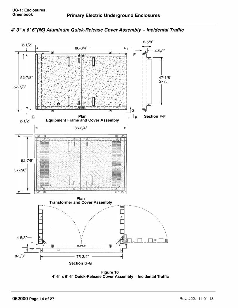
4’ 0” x 6’ 6”(#6) Aluminum Quick-Release Cover Assembly − Incidental Traffic
8-5/8”
Figure 10 4’ 6” x 6’ 6” Quick-Release Cover Assembly − Incidental Traffic
Section F-F
Section G-G
F
F
G
G
PlanEquipment Frame and Cover Assembly
57-7/8”
52-7/8”
86-3/4”
75-3/4”
47-1/8”Skirt
4-5/8”
8-5/8”
4-5/8”
2-1/2”
2-1/2”
PlanTransformer and Cover Assembly
86-3/4”
57-7/8”
52-7/8”
Section F-F

UG-1: EnclosuresGreenbookPrimary Electric Underground Enclosures
Rev. #22: 11-01-18 062000 Page 15 of 27
4’ 0” x 6’ 6” (#6) Steel Quick-Release Cover Assembly − Full Traffic
Figure 11 4’ 0” x 6’ 6” Steel Quick-Release Cover Assembly − Full Traffic
Side View (open)
8-5/8”
Section I-I
H
52-7/8”
86-3/4”2-1/2”
H2-1/2”II
4-5/8”
8-5/8”
75-3/4”
47-1/8”Skirt
PlanEquipment Frame and Cover Assembly
Section H-H

UG-1: EnclosuresGreenbook Primary Electric Underground Enclosures
Rev. #22: 11-01-18062000 Page 16 of 27
4’ 0” x 6’ 6” (#6) Steel Quick-Release Cover Assembly − Full Traffic (continued)
Figure 12 4’ 0” x 6’ 6” Steel Quick-Release Cover Assembly − Full Traffic
Side View (open)
Section J-J
Section K-K
75-3/4”
86-3/4”
2-1/2”
J
J
KK
47-1/8”Skirt
52-7/8”
4-5/8”
2-1/2”
8-5/8”

UG-1: EnclosuresGreenbookPrimary Electric Underground Enclosures
Rev. #22: 11-01-18 062000 Page 17 of 27
4’ 0” x 6’ 6” (#6) Heavy Full-Traffic Cover Assemblies
Figure 13 4’ 0” x 6’ 6” Heavy Full-Traffic Cover Assembly
Grated Heavy Full-Traffic Cast Iron Insert
Solid Heavy Full-Traffic Cast Iron Insert
BaffleHeavy Full-Traffic Frame
4’ 11” OD
7’ 5” OD
6-1/2”
5”
7’ 3-1/2”
Heavy Full-Traffic Cover
4’ 9-1/2”
5”
4.5”
Table 9 Component PartsDescription Weight Code
4’ 0” x 6’ 6”, HFVT Concrete Cover Without Inserts 3,835 lbs. 0419264’ 0” x 6’ 6”, HFVT 5’ x 5’ x 1/2” Steel Frame With Adjustment Feature 339 lbs. 041927
Cast Iron Grate Inserts for Transformer Enclosures 120 lbs. 040346Cast Iron Solid Inserts for Splice Equipment Enclosures 180 lbs. 040343
Baffle 25 lbs. 360036
Table 10 4’ 0” x 6’ 6” Cable Tail Lengths for Estimating 1
4’ 0” x 6’ 6” 28’Horizontal TX Enclosure (Sec. Entrance Side) 26’ Primary/ 7’ Secondary
Horizontal TX Enclosure (Opp. Sec. Entrance Side) 15’ Primary/ 15’ Secondary1 Cable tail length for 3’ 0” x 5” 0” and 4’ 6” x 8’ 6” enclosures are found on the Electric Design Manual under the
Underground 10.10 Section, Table 10 − 4.

UG-1: EnclosuresGreenbook Primary Electric Underground Enclosures
Rev. #22: 11-01-18062000 Page 18 of 27
4’ 6” x 8’ 6” (#7) Complete Enclosure AssembliesNotes1. Swedge reducers are necessary with conduit smaller than 6 inches (see Document 062288).
Figure 144’ 6” x 8’ 6” Enclosure Assembly
(not to scale)
Table 11 Complete Enclosure Assembly (for 600-amp distribution)Application Enclosure Size Type of Traffic Type of Cover Code 1
3∅ Duplex Transformer 24’ 6” x 8’ 6” x 6’ 0” Incidental
Quick-Release Aluminum 043371
4’ 6” x 8’ 6” x 6’ 0” Full-Traffic Quick-Release Steel 0416494’ 6” x 8’ 6” x 7’ 0” Heavy Full-Traffic Concrete 041439
Equipment 34’ 6” x 8’ 6” x 6’ 0” Incidental
Quick-Release Aluminum 043411
4’ 6” x 8’ 6” x 6’ 0” Full-Traffic Quick-Release Steel 0416664’ 6” x 8’ 6” x 7’ 0” Heavy Full-Traffic Concrete 041441
UCD Transformer 44’ 6” x 8’ 6” x 7’ 6” Incidental
Quick-Release Aluminum 040325
4’ 6” x 8’ 6” x 7’ 6” Full-Traffic Quick-Release Steel 0416624’ 6” x 8’ 6” x 8’ 6” Heavy Full-Traffic Concrete 040324
1 Code includes body, extension (as appropriate), frame, and cover assembly. When extra depth is required, orderadditional extension from Table 13 on Page 20.
2 See Document 051776.3 600-amp non-lead splices, 600-amp switches, 600-amp separable connectors.4 112.5 through 500 kVA UCD transformers with 4-hole secondary spades will fit into existing 4’ 6” x 8’ 6” x 6’ 0”
enclosures.

UG-1: EnclosuresGreenbookPrimary Electric Underground Enclosures
Rev. #22: 11-01-18 062000 Page 19 of 27
4’ 6” x 8’ 6” (#7) Complete Enclosure Assemblies (continued)Table 12 Complete Frame and Cover Assembly
Type of Enclosure Type of Traffic Type of cover Code
TransformerIncidental Quick-Release Aluminum 031830
Full-Traffic1 Quick-Release Steel 041055Heavy Full-Traffic Concrete 041442
EquipmentIncidental Quick-Release Aluminum 040642
Full-Traffic1 Quick-Release Steel 041054Heavy Full-Traffic Concrete 041443
1 For application guide, see Note 21 on Page 3.

UG-1: EnclosuresGreenbook Primary Electric Underground Enclosures
Rev. #22: 11-01-18062000 Page 20 of 27
4’ 6” x 8’ 6” (#7) Enclosure and Extensions
Notes1. Do not break out sump.
2. Joints must be interchangeable with those shown in Detail B and approved by PG&E electric distributionpersonnel.
Figure 15 4’ 6” x 8’ 6” Enclosure and Extensions
CL CL
Plan
1-1/4” x 2” HoleNot Required
16-6” ∅ Duct Terminators
Flush Pull IronFive Places
1-1/4” x 1-1/2” Hole Not Required
Seven-5” ∅ Duct Terminators
Tongue and GrooveEnclosure
Width = 30”Length = 54”
Detail B Tongue and Groove
1” ∅ Hole forGround Rod TwoPlaces (blind)
14” ∅ Sump4” Deep Reqd.(see Note 8 onPage 1)
11”
9”
7”
9”
11”
9” 9”
9” 9” 19−1/2”9”
4’ 6”
5’ 6”6”
6” Min.
2-3/4”
6”
11”
9’ 6”
8’ 6”
2-1/4”
2-1/4”1-1/2”
3”
6”
6”
1-3/8”
22” 19”
23”
6’ 0”
1-3/4”
7-1/2”
4-1/4”
24”
11”
10”
Section L-L
M
Section M-M
Not Required
15”
4-1/4”
15”
2 − 1/2” ∅ Brass Insertwith Rod Attached toRebar Cage
7”
30”
M
LL
Table 13 Parts for Enclosure Replacement (Figure 15)Item Description Code Weight - Approximate (lbs.)
1 Body, 72” Depth 043376 17,5202 Extension, 6” Depth 041094 1,0703 Extension, 12” Depth 043415 2,1404 Extension, 18” Depth 043377 3,210

UG-1: EnclosuresGreenbookPrimary Electric Underground Enclosures
Rev. #22: 11-01-18 062000 Page 21 of 27
4’ 6” x 8’ 6” (#7) Aluminum Quick-Release Cover Assembly - Incidental Traffic
58-7/8”
58-7/8”
ÎÎÎÎÎÎÎÎÎÎÎÎÎÎÎÎÎÎÎÎÎÎÎÎÎÎÎÎÎÎÎÎÎÎÎÎÎÎÎÎÎÎÎÎÎÎÎÎÎÎÎÎÎÎÎÎÎÎÎÎÎÎÎÎÎÎÎÎÎÎÎÎÎÎÎÎÎÎÎÎÎÎÎÎÎÎÎÎÎÎÎÎÎÎÎÎÎÎÎÎÎÎÎÎÎÎÎÎÎÎÎÎÎÎÎÎÎÎÎÎÎÎÎÎÎÎ
ÎÎÎÎÎÎÎÎÎÎÎÎÎÎÎÎÎÎÎÎÎÎÎÎÎÎÎÎÎÎÎÎÎÎÎÎÎÎÎÎÎÎÎÎÎÎÎÎÎÎÎÎÎÎÎÎÎÎÎÎÎÎÎÎÎÎÎÎÎÎÎÎÎÎÎÎÎÎÎÎÎÎÎÎÎÎÎÎÎÎÎÎÎÎÎÎÎÎÎÎÎÎÎÎÎÎÎÎÎÎÎÎÎÎÎÎÎÎÎÎÎÎÎÎÎÎÎÎÎÎÎÎÎÎÎ
Figure 16 4’ 6” x 8’ 6” Quick-Release Cover Assembly - Incidental Traffic
End View
PlanEquipment Frame and Cover Assembly
Side View (Closed) Side View (open)
8-1/4”
99-5/8”110-3/4”
4-9/16”
53”
See Detail C and Detail Don Page 25 for GradeAdjustment Feature
53-1/4”110-3/4”
1-3/4”
11-1/8”
See Detail C and Detail D on Page 25for Grade Adjustment Feature
53-1/4”110-3/4”
1-3/4”
PlanTransformer Frame and Cover Assembly
See Note 13on Page 2

UG-1: EnclosuresGreenbook Primary Electric Underground Enclosures
Rev. #22: 11-01-18062000 Page 22 of 27
4’ 6” x 8’ 6”(#7) Steel Quick-Release Cover Assembly− Full Traffic
8-5/8”
Figure 174’ 6” x 8’ 6” Steel Quick-Release Cover Assembly − Full Traffic
110-13/16”
34-1/8” 38-5/16” 34-1/8”
58-7/8”
PlanEquipment Frame and Cover Assembly
Side View
110-13/16”
34-1/8” 34-1/8”38-5/16”
58-7/8”
PlanTransformer Frame and Cover Assembly
Isometric View
4-5/8”
99-15/16”

UG-1: EnclosuresGreenbookPrimary Electric Underground Enclosures
Rev. #22: 11-01-18 062000 Page 23 of 27
4’ 6” x 8’ 6” (#7) Heavy Full-Traffic Cover Assemblies
Figure 18 4’ 6” x 8’ 6” Heavy Full-Traffic Cover Assembly
Grated Heavy Full-Traffic Cast Iron Insert
Solid Heavy Full-Traffic Cast Iron Insert
Baffle
9’ 2-1/2”
5’ 2-1/2”
Heavy Full-Traffic Cover
Heavy Full-Traffic Frame
5’ 4” OD
9’ 4” OD
4-1/2”9”
6-1/2”
5”
Table 14 Component PartsDescription Weight Code
4’ 6” x 8’ 6”, HFVT Concrete Cover Without Inserts 3,840 lbs. 0403404’ 6” x 8’ 6”, HFVT 5’ x 5’ x 1/2” Steel Frame With Adjustment Feature 450 lbs. 040341
Cast Iron Grate Inserts for Transformer Enclosures 120 lbs. 040346Cast Iron Solid Inserts for Splice Equipment Enclosures 180 lbs. 040343
Baffle 25 lbs. 360036

UG-1: EnclosuresGreenbook Primary Electric Underground Enclosures
Rev. #22: 11-01-18062000 Page 24 of 27
Transformer Laser Cut Cover Assembly (Incidental Traffic Shown)
Figure 19 3’ x 5’ (#5) Transformer Assembly − Vent Slot Detail
Figure 20 4’ 0” x 6’ 6” (#6) Transformer Assembly − Vent Slot Detail
PLAN
PLAN
70-1/2”33-1/4”
6 1/8” 16 1/8”5 1/4” 5 1/4”
1/2”
16 1/8”5 1/4” 5 1/4”
1/2”
6 1/8”5 1/4”
Typical Vent Slot Spacing
5 1/4” 5 1/4”
1/2”
1 5/
16”
7/16
”
5 1/4”
Typical Vent Slot Area = 2.26 in 2Total Open Area per Assembly = 225.6 in 2
40 7
/8”
31 1
/8”
25 E
a. S
lots
@ 1
5/1
6” O
.C.
4 1/
16”
4 1/
16”
85”
Typical Vent Slot Spacing
54 5
/8”
32 1
3/16
”
26 E
a. S
lots
@ 1
5/1
6” O
.C.10
7/8
”10
7/8
”
7 1/2”4 1/2”
1/2”1/2”
18 1/2”18 1/2”
4 1/2”
4 1/2”7 1/2”
1/2”
4 1/2”
1/2”
1/2”
4 1/2” 4 1/2”
1/2”
R 7/8”Typ
7/16
”T
typ
4 1/2”7/16”
7/16” R 7/8”Typ
1 5/
16”
Typical Vent Slot Area = 1.93 in 2Total Open Area per Assembly = 300.7 in 2
33-1/4”
Note:Although the 4’ 0” x 6’ 6” (#6) cover has slightly different dimensions than the cover shown on Figure 10 onPage 14, this cover fits on the #6 body enclosure just as well as the cover shown on Figure 10 on Page 14.

UG-1: EnclosuresGreenbookPrimary Electric Underground Enclosures
Rev. #22: 11-01-18 062000 Page 25 of 27
Transformer Laser Cut Cover Assembly (continued)
Plan
Figure 21 4’ 6” x 8’ 6” (#7) Transformer Assembly − Vent Slot Detail
110 3/4”53 1/4” 53 1/4”
6 7/8”
6 1/4” 33 3/8” 33 3/8”1/2”
6 1/4”
Typical Vent Slot Spacing
1/2”
6 1/4”
6 1/4”
6 7/8”
58 7
/8”
48 9
/16”
5 1/
8”
38 E
a. S
lots
@ 1
5/1
6” O
.C.
5 1/
8” 6 1/4” 6 1/4”
7/16
”7/
16”
Typ.
7/16”6 1/4”
R 7/32”Typ
1/2”
Typical Vent Slot Area = 2.70 in 2Total Open Area per Assembly = 409.4 in 2
Notes
1. Laser cut transformer quick-release cover assembly is an approved design for incidental and full-traffic coverassemblies.
2. Material codes for ordering laser cut cover assemblies are the same as the fiberglass grate insert coverassemblies. Therefore, either type of transformer quick-release cover assembly will be shipped.
3. Design complies with th Americans with Disabilities Act (ADA) Section 30.2.
Details for Frame Assemblies
Detail C Grade Adjusting Bolt
Detail D Grade Adjusting Feature
Detail E Adjustment Bolt Support Bracket
Use M041601 Code to OrderSee Detail E
Weld Nutto FrameGrout
12-Gauge Metal1” Radius
10° ±
6”2”
2-1/2”
2-1/2”
3-1/2”
2-1/2”

UG-1: EnclosuresGreenbook Primary Electric Underground Enclosures
Rev. #22: 11-01-18062000 Page 26 of 27
Cement Grouting Instructions for All Enclosure Frame
Frame
Grade Adjusting Bolt(see Detail C on Page 25)
Enclosure Bodyor Extension
Adjustment BoltSupport Bracket
1Grout
Figure 22 Grouting Incidental Enclosure Frame
Female Keyway
Table 15 Grouting Material (structural - Figure 22)Item Quantity Description Code1 1 Sack - 55 lbs. Grout, Zero Shrink, High-Early Strength 121016
1 One sack of grout is required for approximately each 1/2” of space between theenclosure and the frame on a 4’ 6” x 8’ 6” enclosure.
InstructionsStep 1. Thoroughly clean all surfaces of the enclosure that the grout will contact. Use clean water to remove dust
from surfaces.
Step 2. Remove sufficient soil from around the enclosure to preclude accidentally mixing dirt with the grout. Install theenclosure frame and adjust it to grade.
Step 3. Saturate all grout-contact surfaces of the enclosure with water for as long as possible before grouting usingwet rags laid in and around the keyway. The recommended minimum saturation time is 24 hours.Re-saturate the keyways with water before leaving the job. Remove excess water from the female keywayjust prior to grouting.
Step 4. Mix grout in a wheelbarrow with clean water. Do not mix more grout than can be easily used within 15 minutes. The consistency of the grout should allow it to flow under pressure.
Step 5. Install the grout directly from a shovel onto the enclosure using hands with gloves. After an adequate amountof grout has been applied, use a trowel to apply additional pressure to the grout so that all voids are filled andthe grout is completely consolidated. This is necessary to ensure a full bearing surface for the frame.
Step 6. After wiping off any excess grout and making sure that all voids are filled with grout, cover the grout surfacewith water-saturated rags. While on the job, moisten the rags often. Re-saturate the rags with water beforeleaving the job. The water-saturated rags are required to cure the grout properly.
Step 7. Keep wet rags on and traffic off the enclosure for 24 hours to allow the grout to set up properly.
Step 8. Do not backfill and tamp around the enclosure until the set-up period has concluded.
Step 9. Remove the rags before backfilling around the enclosure.
Step 10. Repair any damaged grout by repeating the above procedure.
Step 11. Ready-mix concrete (5-sack mix) is an acceptable alternate.

UG-1: EnclosuresGreenbookPrimary Electric Underground Enclosures
Rev. #22: 11-01-18 062000 Page 27 of 27
Revision Notes
Revision 22 has the following changes:
1. Revised Note 23 on Page 3.
2. Revised Notes 1 and 3 on Page 4.
