primergy bx900/bx400 blade server systems -...
TRANSCRIPT

Configuration Guide
PRIMERGY BX900/BX400 Blade Server Systems Ethernet Connection Blade Module SB6 / SB11a / SB11 Switch VersionEnglish


PRIMERGY BX400/BX900 Connection Blades
Ethernet Connection Blades
PY CB Eth Switch/IBP 1 GB 18/6 (SB6) PY CB Eth Switch/IBP 1 GB 36/12 (SB11a) PY CB Eth Switch/IBP 1 GB 36/8+2 (SB11)
Configuration Guide
Switch Version
Edition Jan 2012

© 2011 Fujitsu Technology Solutions 2
Comments… Suggestions… Corrections…
The User Documentation Department would like to know your opinion on this manual. Your feedback helps us to optimize our documentation to suit your individual needs.
Fax forms for sending us your comments are included at the back of the manual. There you will also find the addresses of the relevant User documentation Department.
Copyright and Trademarks
Copyright © 2011 Fujitsu Technology Solutions GmbH.
All rights reserved.
Delivery subject to availability; right of technical modifications reserved.
All hardware and software names used are trademarks of their respective manufacturers

© 2011 Fujitsu Technology Solutions 3
Content
1 Configuration Guide Overview ................................................................................ 6
2 Configuring VLANs .................................................................................................. 7 2.1 Creating a VLAN ........................................................................................................ 7 2.2 Configuring VLAN Members ..................................................................................... 10 2.3 Configuring Untagged VLAN (Access Port) .............................................................. 13 2.4 Configuring Tagged VLAN (Trunk Port) .................................................................... 15 2.5 Configuring Protocol VLAN ....................................................................................... 17
3 Configuring Link Aggregation ............................................................................... 19 3.1 Configuring Link Aggregation with LACP .................................................................. 19 3.2 Configuring Static Link Aggregation .......................................................................... 21 3.3 Configuring Load Balance of Link Aggregation ......................................................... 23
4 Configuring Port-Backup ....................................................................................... 25 4.1 Creating Port-backup group...................................................................................... 25 4.2 Configuring Active port and Backup port .................................................................. 27
5 Configuring MAC Filtering ..................................................................................... 29 5.1 Configuring MAC filter which passes only packets of the specific source MAC address ........................................................................................................................... 29 5.2 Configuring MAC filter which passes only packets of specified destination MAC address ........................................................................................................................... 31 5.3 Configuring MAC filter which rejects only packets of the specified packet format MAC address ................................................................................................................ 33 5.4 Configuring MAC filter which rejects only traffic between the specified MAC addresses in VLAN................................................................................................................... 35 5.5 Configuring MAC filter which passes only the traffic between the specified MAC addresses in VLAN .......................................................................................................... 37
6 Configuring Static MAC Forwarding ..................................................................... 39
7 Configuring QoS ..................................................................................................... 42 7.1 Configuring priority control ........................................................................................ 42 7.2 Configuring priority control rewrite ............................................................................ 44 7.2.1 IP Precedence value rewrite ..................................................................................... 44 7.2.2 Change queue of packets in VLAN ........................................................................... 47
8 Configuring Spanning Tree ................................................................................... 49 8.1 Configuring Spanning Tree Mode ............................................................................. 49 8.2 Configuring MSTP .................................................................................................... 52
9 Configuring IGMP snooping & Querier ................................................................. 54 9.1 Configuring IGMP snooping by interface .................................................................. 54 9.2 Configuring IGMP snooping by VLAN ....................................................................... 59 9.3 Configuring IGMP snooping static router port ........................................................... 61 9.4 Configuring IGMP snooping static group member .................................................... 63 9.5 Configuring IGMP Snooping Querier by VLAN ......................................................... 64
10 Configuring MLD Snooping & Querier .................................................................. 66 10.1 Configuring MLD Snooping by interface ................................................................... 66 10.2 Configuring MLD Snooping by VLAN ........................................................................ 69 10.3 Configuring MLD Snooping static router port ............................................................ 71 10.4 Configuring MLD Snooping static group member ..................................................... 73 10.5 Configuring MLD Snooping Querier by VLAN ........................................................... 74
© 2011 Fujitsu Technology Solutions 4
11 Configuring IEEE 802.1X Authentication .............................................................. 76 11.1 Using Local User Name/ Password .......................................................................... 76 11.2 Using Remote RADIUS Server ................................................................................. 78
12 Configuring Port Mirroring .................................................................................... 80
13 Configuring IP Filtering .......................................................................................... 81 13.1 Configuring IP filter which passes only packets to the specified service ................... 81
14 Configuring SNMP Agent ....................................................................................... 83 14.1 Configuring SNMP Community ................................................................................. 83 14.2 Configuring SNMP User ........................................................................................... 84 14.3 Configuring SNMP Remote EngineID ....................................................................... 85 14.4 Configuring SNMP Traps .......................................................................................... 86 14.5 Configuring SNMP Informs ....................................................................................... 87
15 Configuring System Log ........................................................................................ 88
16 Configuring Pin Group ........................................................................................... 90 16.1 End-Host-Mode Overview ........................................................................................ 90 16.2 Creating Pin Group ................................................................................................... 91 16.3 Configuring Pin Group Members .............................................................................. 92 16.4 Configuring Auto VLAN Uplink Synchronization ........................................................ 94 16.5 Configuring Pinning State ......................................................................................... 96

© 2011 Fujitsu Technology Solutions 5
Revision History
Revision Date Editor Remark 0.1 12/22/2008 Switch Team
Moore C. J. Lee 1st Draft
0.2 2/18/2009 Moore C. J. Lee Review & Correct 0.3 1/31/2011 Moore C. J. Lee Add SNMP informs 0.4 7/29/2011 Moore C. J. Lee End-Host-Mode 0.5 9/28/2011 Moore C. J. Lee Update EHM Configuration 0.55 1/19/2012 E.Schröer Merged SB6 / SB11/ SB11a

© 2011 Fujitsu Technology Solutions 6
1 Configuration Guide Overview This guide describes the PRIMERGY BX400/BX900 Ethernet Connection Blade specific functions that you might encounter. Basically, the guide describes how to configure your switch or how to configure software features on your switch. It also provides detailed information about commands that have been created or changed for use by the connection blade.
Where “BX900” is shown in the examples below, it is synonymous to “BX400” when working on a Primergy BX400 Blade Server System.
This document provides the following guidelines:
− Configuring VLANs
− Configuring Link Aggregation
− Configuring Backup Port
− Configuring MAC Filtering
− Configuring Static MAC Forwarding
− Configuring QoS
− Configuring Spanning Tree
− Configuring IGMP Snooping & Querier
− Configuring MLD Snooping & Querier
− Configuring IEEE 802.1X Authentication
− Configuring Port Mirroring
− Configuring IP Filtering
− Configuring SNMP Agent
− Configuring System Log
− Configuring Pin Group
Mode Prompt privileged EXEC mode (BX900-CB1)# Configuration mode (BX900-CB1)(Config)# Interface mode (BX900-CB1)(Interface BX900-CB1/0/1)# Interface range mode (BX900-CB1)(if-range)# Vlan database mode (BX900-CB1)(Vlan)# MAC access list mode (BX900-CB1)(Config-mac-access-list)# DiffServ class map mode (BX900-CB1)(Config-classmap)# DiffServ policy map mode (BX900-CB1)(Config-policy-map)#

© 2011 Fujitsu Technology Solutions 7
2 Configuring VLANs This chapter describes how to configure the VLANs in the PRIMERGY BX900 Ethernet Connection Blade system.
2.1 Creating a VLAN
This section describes how to create a VLAN on the system.
Beginning in privileged EXEC mode, follow these steps to create a VLAN on system:
Command Purpose Step 1 configure Enter global configuration mode. Step 2 vlan database Enter VLAN database mode. Step 3 vlan vlan-id To create a VLAN with VLAN ID. Step 4 exit Return to global configuration mode. Step 5 exit Return to privileged EXEC mode. Step 6 show vlan Verify the configuration.
To create a VLAN on system, use the vlan vlan-id VLAN database configuration command. To display the VLAN information, use show vlan privileged EXEC command.
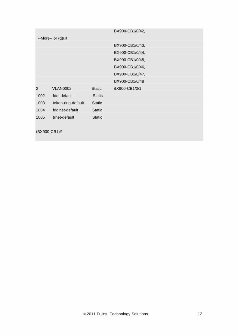
In this example, VLAN 2 is created without any members.
(BX900-CB1)#configure
(BX900-CB1)(Config)#vlan database
(BX900-CB1)(Vlan)#vlan 2
(BX900-CB1)(Vlan)#exit
(BX900-CB1)(Config)#exit
(BX900-CB1)#show vlan
VLAN ID VLAN Name VLAN Type Interface(s)
------- -------------------------------- ---------- -------------------------
1 Default Default BX900-CB1/0/1,
BX900-CB1/0/2,
BX900-CB1/0/3,
BX900-CB1/0/4,
BX900-CB1/0/5,
BX900-CB1/0/6,

© 2011 Fujitsu Technology Solutions 8
BX900-CB1/0/7,
BX900-CB1/0/8,
BX900-CB1/0/9,
BX900-CB1/0/10,
BX900-CB1/0/11,
BX900-CB1/0/12,
BX900-CB1/0/13,
BX900-CB1/0/14,
BX900-CB1/0/15,
BX900-CB1/0/16,
BX900-CB1/0/17,
BX900-CB1/0/18,
BX900-CB1/0/19,
--More-- or (q)uit
BX900-CB1/0/20,
BX900-CB1/0/21,
BX900-CB1/0/22,
BX900-CB1/0/23,
BX900-CB1/0/24,
BX900-CB1/0/25,
BX900-CB1/0/26,
BX900-CB1/0/27,
BX900-CB1/0/28,
BX900-CB1/0/29,
BX900-CB1/0/30,
BX900-CB1/0/31,
BX900-CB1/0/32,
BX900-CB1/0/33,
BX900-CB1/0/34,
BX900-CB1/0/35,
BX900-CB1/0/36,
BX900-CB1/0/37,
BX900-CB1/0/38,
BX900-CB1/0/39,
BX900-CB1/0/40,
BX900-CB1/0/41,
BX900-CB1/0/42,

© 2011 Fujitsu Technology Solutions 9
--More-- or (q)uit
BX900-CB1/0/43,
BX900-CB1/0/44,
BX900-CB1/0/45,
BX900-CB1/0/46,
BX900-CB1/0/47,
BX900-CB1/0/48
2 VLAN0002 Static
1002 fddi-default Static
1003 token-ring-default Static
1004 fddinet-default Static
1005 trnet-default Static
(BX900-CB1)#

© 2011 Fujitsu Technology Solutions 10
2.2 Configuring VLAN Members
This section describes how to add / remove members of a VLAN and change native VLAN.
Beginning in privileged EXEC mode, follow these steps to configure the members of a VLAN:
Command Purpose Step 1 configure Enter global configuration mode. Step 2 interface interface-id Specify the interface, and enter interface
configuration mode. The interface can be a physical Layer 2 interface or a port channel (logical interface).
Step 3 switchport allowed vlan add vlan-id or switchport allowed vlan remove vlan-id
To add/remove an interface to/from a VLAN.
Step 4 switchport native vlan vlan-id To change the port VLAN ID to new one. Step 5 exit Return to global configuration mode. Step 6 exit Return to privileged EXEC mode. Step 7 show vlan id vlan-id Verify the configuration.
To create a VLAN on system, use the vlan vlan-id VLAN database configuration command. To add/remove an interface to/from a VLAN, use switchport allowed vlan add/switchport allowed vlan remove interface configuration command. To display the VLAN information, use show vlan privileged EXEC command.
In this example, VLAN 2 was created without any members. Interface 0/1 is added to VLAN2 and is removed from VLAN 1.
(BX900-CB1)#configure
(BX900-CB1)(Config)#interface 0/1
(BX900-CB1)(Interface BX900-CB1/0/1)#switchport allowed vlan add 2
(BX900-CB1)(Interface BX900-CB1/0/1)#switchport native vlan 2
(BX900-CB1)(Interface BX900-CB1/0/1)#switchport allowed vlan remove 1
(BX900-CB1)(Interface BX900-CB1/0/1)#exit
(BX900-CB1)(Config)#exit
(BX900-CB1)#show vlan
VLAN ID VLAN Name VLAN Type Interface(s)
------- -------------------------------- ---------- -------------------------
1 Default Default BX900-CB1/0/2,
BX900-CB1/0/3,

© 2011 Fujitsu Technology Solutions 11
BX900-CB1/0/4,
BX900-CB1/0/5,
BX900-CB1/0/6,
BX900-CB1/0/7,
BX900-CB1/0/8,
BX900-CB1/0/9,
BX900-CB1/0/10,
BX900-CB1/0/11,
BX900-CB1/0/12,
BX900-CB1/0/13,
BX900-CB1/0/14,
BX900-CB1/0/15,
BX900-CB1/0/16,
BX900-CB1/0/17,
BX900-CB1/0/18,
BX900-CB1/0/19,
--More-- or (q)uit
BX900-CB1/0/20,
BX900-CB1/0/21,
BX900-CB1/0/22,
BX900-CB1/0/23,
BX900-CB1/0/24,
BX900-CB1/0/25,
BX900-CB1/0/26,
BX900-CB1/0/27,
BX900-CB1/0/28,
BX900-CB1/0/29,
BX900-CB1/0/30,
BX900-CB1/0/31,
BX900-CB1/0/32,
BX900-CB1/0/33,
BX900-CB1/0/34,
BX900-CB1/0/35,
BX900-CB1/0/36,
BX900-CB1/0/37,
BX900-CB1/0/38,
BX900-CB1/0/39,
BX900-CB1/0/40,
BX900-CB1/0/41,
© 2011 Fujitsu Technology Solutions 12
BX900-CB1/0/42,
--More-- or (q)uit
BX900-CB1/0/43,
BX900-CB1/0/44,
BX900-CB1/0/45,
BX900-CB1/0/46,
BX900-CB1/0/47,
BX900-CB1/0/48
2 VLAN0002 Static BX900-CB1/0/1
1002 fddi-default Static
1003 token-ring-default Static
1004 fddinet-default Static
1005 trnet-default Static
(BX900-CB1)#

© 2011 Fujitsu Technology Solutions 13
2.3 Configuring Untagged VLAN (Access Port)
This section describes how to configure interfaces to send untagged packet for specific VLAN.
Beginning in privileged EXEC mode, follow these steps to configure untagged VLAN on specific interface:
Command Purpose Step 1 configure Enter global configuration mode. Step 2 interface interface-id Specify the interface, and enter interface
configuration mode. The interface can be a physical Layer 2 interface or a port channel (logical interface).
Step 3 switchport allowed vlan add [untagged] vlan-id
To add this interface to a VLAN as an access port.
Step 4 exit Return to global configuration mode. Step 5 exit Return to privileged EXEC mode. Step 6 show vlan id vlan-id Verify the configuration.
To configure an interface to be an access port for specific VLAN, use the switchport allowed vlan add [untagged] vlan-id interface configuration command. To display the VLAN information, use show vlan id privileged EXEC command.
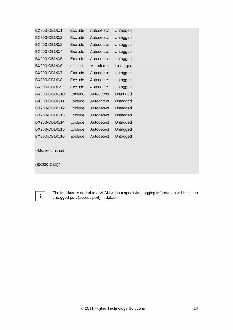
In this example, VLAN 2 is created without any members and interface 0/6 is configured as an access port of VLAN 2:
(BX900-CB1)#configure
(BX900-CB1)(Config)#vlan database
(BX900-CB1)(Vlan)#vlan 2
(BX900-CB1)(Vlan)#exit
(BX900-CB1)(Config)#interface 0/6
(BX900-CB1)(Interface BX900-CB1/0/6)#switchport allowed vlan add 2
(BX900-CB1)(Interface BX900-CB1/0/6)#exit
(BX900-CB1)(Config)#exit
(BX900-CB1)#show vlan id 2
VLAN ID: 2
VLAN Name: VLAN0002
VLAN Type: Static
Interface Current Configured Tagging
----------------- -------- ----------- --------
© 2011 Fujitsu Technology Solutions 14
BX900-CB1/0/1 Exclude Autodetect Untagged
BX900-CB1/0/2 Exclude Autodetect Untagged
BX900-CB1/0/3 Exclude Autodetect Untagged
BX900-CB1/0/4 Exclude Autodetect Untagged
BX900-CB1/0/5 Exclude Autodetect Untagged
BX900-CB1/0/6 Include Autodetect Untagged
BX900-CB1/0/7 Exclude Autodetect Untagged
BX900-CB1/0/8 Exclude Autodetect Untagged
BX900-CB1/0/9 Exclude Autodetect Untagged
BX900-CB1/0/10 Exclude Autodetect Untagged
BX900-CB1/0/11 Exclude Autodetect Untagged
BX900-CB1/0/12 Exclude Autodetect Untagged
BX900-CB1/0/13 Exclude Autodetect Untagged
BX900-CB1/0/14 Exclude Autodetect Untagged
BX900-CB1/0/15 Exclude Autodetect Untagged
BX900-CB1/0/16 Exclude Autodetect Untagged
--More-- or (q)uit
(BX900-CB1)#
i
The interface is added to a VLAN without specifying tagging information will be set to untagged port (access port) in default.

© 2011 Fujitsu Technology Solutions 15
2.4 Configuring Tagged VLAN (Trunk Port)
This section describes how to configure interfaces to send tagged packet for specific VLAN.
Beginning in privileged EXEC mode, follow these steps to configure tagged VLAN on specific interface:
Command Purpose Step 1 configure Enter global configuration mode Step 2 interface interface-id Specify the interface, and enter interface
configuration mode. The interface can be a physical Layer 2 interface or a port channel (logical interface).
Step 3 switchport allowed vlan add [tagged] vlan-id
To add this interface to a VLAN as a trunk port.
Step 4 exit Return to global configuration mode. Step 5 exit Return to privileged EXEC mode. Step 6 show vlan id vlan-id Verify the configuration.
To configure an interface to send tagged packets for specific VLAN, use the switchport allowed vlan add add [tagged] vlan-id interface configuration command. To display the VLAN information, use show vlan id privileged EXEC command.
In this example, the VLAN 2 was created with a member interface 0/6. Interface 0/7 is configured as a trunk port of VLAN 2:
(BX900-CB1)#configure
(BX900-CB1)(Config)#interface 0/7
(BX900-CB1)(Interface BX900-CB1/0/7)#switchport allowed vlan add 2 tagging
(BX900-CB1)(Interface BX900-CB1/0/7)#exit
(BX900-CB1)(Config)#exit
(BX900-CB1)#show vlan id 2
VLAN ID: 2
VLAN Name: VLAN0002
VLAN Type: Static
Interface Current Configured Tagging
----------------- -------- ----------- --------
BX900-CB1/0/1 Exclude Autodetect Untagged
BX900-CB1/0/2 Exclude Autodetect Untagged
BX900-CB1/0/3 Exclude Autodetect Untagged

© 2011 Fujitsu Technology Solutions 16
BX900-CB1/0/4 Exclude Autodetect Untagged
BX900-CB1/0/5 Exclude Autodetect Untagged
BX900-CB1/0/6 Include Autodetect Untagged
BX900-CB1/0/7 Include Autodetect Tagged
BX900-CB1/0/8 Exclude Autodetect Untagged
BX900-CB1/0/9 Exclude Autodetect Untagged
BX900-CB1/0/10 Exclude Autodetect Untagged
BX900-CB1/0/11 Exclude Autodetect Untagged
BX900-CB1/0/12 Exclude Autodetect Untagged
BX900-CB1/0/13 Exclude Autodetect Untagged
BX900-CB1/0/14 Exclude Autodetect Untagged
BX900-CB1/0/15 Exclude Autodetect Untagged
BX900-CB1/0/16 Exclude Autodetect Untagged
--More-- or (q)uit
(BX900-CB1)#
© 2011 Fujitsu Technology Solutions 17
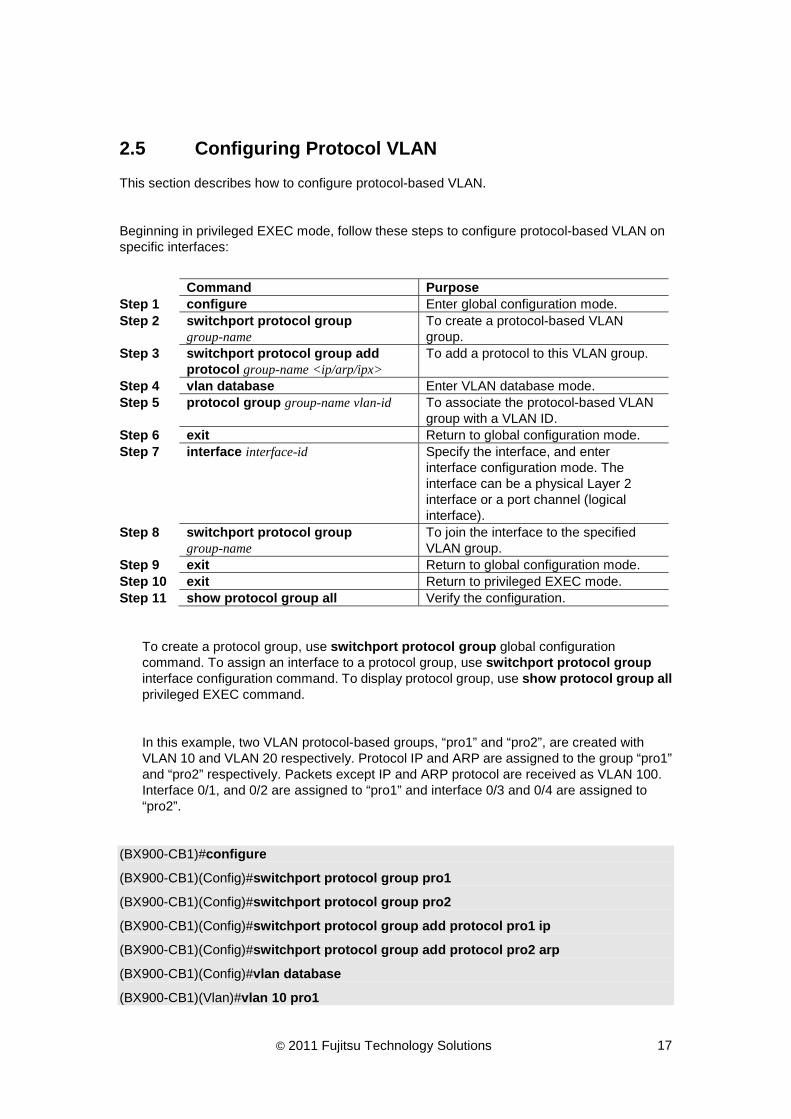
2.5 Configuring Protocol VLAN
This section describes how to configure protocol-based VLAN.
Beginning in privileged EXEC mode, follow these steps to configure protocol-based VLAN on specific interfaces:
Command Purpose Step 1 configure Enter global configuration mode. Step 2 switchport protocol group
group-name To create a protocol-based VLAN group.
Step 3 switchport protocol group add protocol group-name <ip/arp/ipx>
To add a protocol to this VLAN group.
Step 4 vlan database Enter VLAN database mode. Step 5 protocol group group-name vlan-id To associate the protocol-based VLAN
group with a VLAN ID. Step 6 exit Return to global configuration mode. Step 7 interface interface-id Specify the interface, and enter
interface configuration mode. The interface can be a physical Layer 2 interface or a port channel (logical interface).
Step 8 switchport protocol group group-name
To join the interface to the specified VLAN group.
Step 9 exit Return to global configuration mode. Step 10 exit Return to privileged EXEC mode. Step 11 show protocol group all Verify the configuration.
To create a protocol group, use switchport protocol group global configuration command. To assign an interface to a protocol group, use switchport protocol group interface configuration command. To display protocol group, use show protocol group all privileged EXEC command.
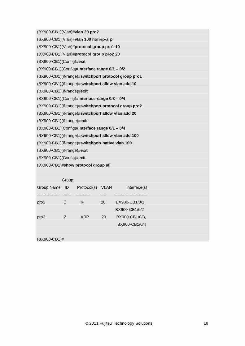
In this example, two VLAN protocol-based groups, “pro1” and “pro2”, are created with VLAN 10 and VLAN 20 respectively. Protocol IP and ARP are assigned to the group “pro1” and “pro2” respectively. Packets except IP and ARP protocol are received as VLAN 100. Interface 0/1, and 0/2 are assigned to “pro1” and interface 0/3 and 0/4 are assigned to “pro2”.
(BX900-CB1)#configure
(BX900-CB1)(Config)#switchport protocol group pro1
(BX900-CB1)(Config)#switchport protocol group pro2
(BX900-CB1)(Config)#switchport protocol group add protocol pro1 ip
(BX900-CB1)(Config)#switchport protocol group add protocol pro2 arp
(BX900-CB1)(Config)#vlan database
(BX900-CB1)(Vlan)#vlan 10 pro1
© 2011 Fujitsu Technology Solutions 18
(BX900-CB1)(Vlan)#vlan 20 pro2
(BX900-CB1)(Vlan)#vlan 100 non-ip-arp
(BX900-CB1)(Vlan)#protocol group pro1 10
(BX900-CB1)(Vlan)#protocol group pro2 20
(BX900-CB1)(Config)#exit
(BX900-CB1)(Config)#interface range 0/1 – 0/2
(BX900-CB1)(if-range)#switchport protocol group pro1
(BX900-CB1)(if-range)#switchport allow vlan add 10
(BX900-CB1)(if-range)#exit
(BX900-CB1)(Config)#interface range 0/3 – 0/4
(BX900-CB1)(if-range)#switchport protocol group pro2
(BX900-CB1)(if-range)#switchport allow vlan add 20
(BX900-CB1)(if-range)#exit
(BX900-CB1)(Config)#interface range 0/1 – 0/4
(BX900-CB1)(if-range)#switchport allow vlan add 100
(BX900-CB1)(if-range)#switchport native vlan 100
(BX900-CB1)(if-range)#exit
(BX900-CB1)(Config)#exit
(BX900-CB1)#show protocol group all
Group
Group Name ID Protocol(s) VLAN Interface(s)
---------------- ------ ----------- ---- ------------------------
pro1 1 IP 10 BX900-CB1/0/1,
BX900-CB1/0/2
pro2 2 ARP 20 BX900-CB1/0/3,
BX900-CB1/0/4
(BX900-CB1)#

© 2011 Fujitsu Technology Solutions 19
3 Configuring Link Aggregation This chapter describes how to configure the Link Aggregation in the PRIMERGY BX900 Connection Blade system.
3.1 Configuring Link Aggregation with LACP
This section describes how to configure link aggregation with LACP with 4 links.
Beginning in privileged EXEC mode, follow these steps to configure link aggregation with LACP:
Command Purpose Step 1 configure Enter global configuration mode. Step 2 port-channel name To create a port-channel. Step 3 interface logical-interface-id Specify the port-channel interface (logical
interface), and enter interface configuration mode.
Step 4 no staticcapability To disable the static mode of the port-channel.
Step 5 exit Return to global configuration mode. Step 6 interface physical-interface-id Specify the interface, and enter interface
configuration mode. Step 7 channel-group logicall-interface-id To join the specified port-channel group. Step 8 exit Return to global configuration mode. Step 9 exit Return to privileged EXEC mode. Step 10 show port-channel all Verify the configuration.
To create a port-channel group, use port-channel global configuration command. To assign an interface to a port-channel group, use channel-group interface configuration command. To display port-channel group, use show port-channel all privileged EXEC command.
In this example, a port-channel group is created and interface 0/1, 0/2, 0/3 and 0/4 are set to the member of this port-channel group.
(BX900-CB1)(Config)#port-channel pc-1
Interface BX900-CB1/1/1 created for port-channel pc-1
(BX900-CB1)(Config)#interface BX900-CB1/1/1
(BX900-CB1)(Interface BX900-CB1/1/1)#no staticcapability
(BX900-CB1)(Interface BX900-CB1/1/1)#exit
(BX900-CB1)(Config)#interface range 0/1 – 0/4
(BX900-CB1)(if-range)#channel-group BX900-CB1/1/1

© 2011 Fujitsu Technology Solutions 20
(BX900-CB1)(if-range)#exit
(BX900-CB1)(Config)#exit
(BX900-CB1)#show port-channel all
Port- Link
Log. Channel Adm. Trap STP Mbr Port Port
Intf Name Link Mode Mode Mode Type LB Ports Speed Active
------ --------------- ------ ---- ---- ------ ---- --- ------ --------- ------
BX900-CB1/1/1 pc-1 Down En. En. En. Dy. SDM BX900-CB1/0/1 Auto False
BX900-CB1/0/2 Auto False
BX900-CB1/0/3 Auto False
BX900-CB1/0/4 Auto False
(BX900-CB1)#

© 2011 Fujitsu Technology Solutions 21
3.2 Configuring Static Link Aggregation
This section describes how to configure link aggregation without LACP with 4 links.
Beginning in privileged EXEC mode, follow these steps to configure link aggregation without LACP:
Command Purpose Step 1 configure Enter global configuration mode. Step 2 port-channel name To create a port-channel. Step 3 interface logical-interface-id Specify the port-channel interface (logical
interface), and enter interface configuration mode.
Step 4 staticcapability To enable the static mode of the port-channel.
Step 5 exit Return to global configuration mode. Step 6 interface physical-interface-id Specify the interface, and enter interface
configuration mode. Step 7 channel-group logical-interface-id To join the specified port-channel group. Step 8 exit Return to global configuration mode. Step 9 exit Return to privileged EXEC mode. Step 10 show port-channel all Verify the configuration.
To create a port-channel group, use port-channel global configuration command. To assign an interface to a port-channel group, use channel-group interface configuration command. To display port-channel group, use show port-channel all privileged EXEC command.
In the following example, a port-channel group is created with static property and interface 0/1, 0/2, 0/3 and 0/4 are set to the member of this port-channel group.
(BX900-CB1)(Config)#port-channel pc-1
Interface BX900-CB1/1/1 created for port-channel pc-1
(BX900-CB1)(Config)#interface BX900-CB1/1/1
(BX900-CB1)(Interface BX900-CB1/1/1)#staticcapability
(BX900-CB1)(Interface BX900-CB1/1/1)#exit
(BX900-CB1)(Config)#interface range 0/1 – 0/4
(BX900-CB1)(if-range)#channel-group BX900-CB1/1/1
(BX900-CB1)(if-range)#exit
(BX900-CB1)(Config)#exit

© 2011 Fujitsu Technology Solutions 22
(BX900-CB1)#show port-channel all
Port- Link
Log. Channel Adm. Trap STP Mbr Port Port
Intf Name Link Mode Mode Mode Type LB Ports Speed Active
------ --------------- ------ ---- ---- ------ ---- --- ------ --------- ------
BX900-CB1/1/1 pc-1 Down En. En. En. St. SDM BX900-CB1/0/1 Auto False
BX900-CB1/0/2 Auto False
BX900-CB1/0/3 Auto False
BX900-CB1/0/4 Auto False
(BX900-CB1)#

© 2011 Fujitsu Technology Solutions 23
3.3 Configuring Load Balance of Link Aggregation
This section describes how to configure link aggregation with load balance settings.
Beginning in privileged EXEC mode, follow these steps to configure link aggregation with load balance settings:
Command Purpose Step 1 configure Enter global configuration mode. Step 2 interface logical-interface-id Specify the port-channel interface (logical
interface), and enter interface configuration mode.
Step 3 load-balance <dst-ip/dst-mac/src-dst-ip/src-dst-mac/src-ip/src-mac>
Set the load balance for the port-channel group.
Step 4 exit Return to global configuration mode. Step 5 exit Return to privileged EXEC mode. Step 6 show port-channel all Verify the configuration.
To set the load balance setting of a port-channel group, use load-balance interface configuration command. To display port-channel group, use show port-channel all privileged EXEC command.
In this example, a port-channel group is set to use source IP and destination IP for its load balance setting.
(BX900-CB1)(Config)#port-channel pc-1
Interface BX900-CB1/1/1 created for port-channel pc-1
(BX900-CB1)(Config)#interface BX900-CB1/1/1
(BX900-CB1)(Interface BX900-CB1/1/1)#load-balance src-dst-ip
(BX900-CB1)(Interface BX900-CB1/1/1)#exit
(BX900-CB1)(Config)#exit
(BX900-CB1)#show port-channel all
Port- Link
Log. Channel Adm. Trap STP Mbr Port Port
Intf Name Link Mode Mode Mode Type LB Ports Speed Active
------ --------------- ------ ---- ---- ------ ---- --- ------ --------- ------
BX900-CB1/1/1 pc-1 Down En. En. En. St. SDI BX900-CB1/0/1 Auto False
BX900-CB1/0/2 Auto False
BX900-CB1/0/3 Auto False
BX900-CB1/0/4 Auto False

© 2011 Fujitsu Technology Solutions 24
(BX900-CB1)#

© 2011 Fujitsu Technology Solutions 25
4 Configuring Port-Backup This chapter describes how to configure port-backup.
4.1 Creating Port-backup group
This section will describe how to create a port-backup group and how to enable the port-backup group.
Beginning in privileged EXEC mode, follow these steps to create port-backup group:
Command Purpose Step 1 configure Enter global configuration mode. Step 2 port-backup group To create a port-backup group. Step 3 port-backup To enable the port-backup admin mode. Step 4 port-backup group enable
group-id To enable a specific port-backup group.
Step 5 exit Return to privileged EXEC mode. Step 6 show port-backup Verify the configuration.
To create a port-backup group, use port-backup group global configuration command. To enable the created port-backup group, use port-backup group enable group-id interface configuration command. To display the port-backup information, use show port-backup privileged EXEC command.
!
The port-backup group could only be enabled if both of active and backup ports have been assigned.
In this example, a port group is created and it is tried to be enabled.
(BX900-CB1)#configure
(BX900-CB1)(Config)#port-backup group
Port backup group 1 is created
(BX900-CB1)(Config)#port-backup
(BX900-CB1)(Config)#port-backup group enable 1
port pair should be configured before enabling this group.
(BX900-CB1)(Config)#exit
(BX900-CB1)#show port-backup

© 2011 Fujitsu Technology Solutions 26
Admin Mode: Enable
Group ID Mode Active Port Backup Port Current Active Port
--------- ----------- ------------ ------------ --------------------
1 Disable
(BX900-CB1)#

© 2011 Fujitsu Technology Solutions 27
4.2 Configuring Active port and Backup port
This section describes how to configure active port and backup port for a port-backup group.
Beginning in privileged EXEC mode, follow these steps to configure active port and backup port:
Command Purpose Step 1 configure Enter global configuration mode. Step 2 port-backup group To create a port backup group. Step 3 interface interface-id Specify the physical interface or logical
interface with uplinks, then enter interface configuration mode.
Step 4 port-backup group group-id active Set the interface to the specific port-backup group as an active port.
Step 5 interface interface-id Specify the physical interface or logical interface with uplinks, then enter interface configuration mode.
Step 6 port-backup group group-id backup
Set the interface to the specific port-backup group as a backup port.
Step 7 exit Return to global configuration mode. Step 8 port-backup group enable
group-id To enable the port-backup group.
Step 9 exit Return to privileged EXEC mode. Step 10 show port-backup Verify the configuration.
To create a port-backup group, use port-backup group global configuration command. To set an interface to be the active port of a port-backup group, use port-backup group group-id active interface configuration command. To set an interface to be the backup port of a port-backup group, use port-backup group group-id backup interface configuration command.
In this example, interface 0/40 is set to the active port and interface 0/41 is set to the backup port of the port-backup group.
(BX900-CB1)#configure
(BX900-CB1)(Config)#port-backup group
Port backup group 2 is created
(BX900-CB1)(Config)#interface BX900-CB1/0/40
(BX900-CB1)(Interface BX900-CB1/0/40)#port-backup group 2 active
(BX900-CB1)(Interface BX900-CB1/0/40)#interface BX900-CB1/0/41
(BX900-CB1)(Interface BX900-CB1/0/41)#port-backup group 2 backup
(BX900-CB1)(Interface BX900-CB1/0/41)#exit
(BX900-CB1)(Config)#port-backup group enable 2
(BX900-CB1)(Config)#exit

© 2011 Fujitsu Technology Solutions 28
(BX900-CB1)#show port-backup
Admin Mode: Enable
Group ID Mode Active Port Backup Port Current Active Port
--------- ------- ------------ ------------ --------------------
1 Disable
2 Enable BX900-CB1/0/40 BX900-CB1/0/41
(BX900-CB1)#
© 2011 Fujitsu Technology Solutions 29
5 Configuring MAC Filtering This chapter describes how to configure MAC filtering which can limit network traffic and restrict network for security with combination of MAC address, Packet, Ethernet type, VLAN ID and CoS value.
5.1 Configuring MAC filter which passes only packets of the specific source MAC address
This section describes how to configure MAC filter which passes only packets of the specified source MAC address and rejects the other packets.
Beginning in privileged EXEC mode, follow these steps to configure ACL MAC filter on specific interface:
Command Purpose Step 1 configure Enter global configuration mode Step 2 mac access-list extended acl
–name Create a new extended MAC access-list with a name.
Step 3 permit xx:xx:xx:xx:xx:xx 00:00:00:00:00:00 any
Create a new matching rule for specific source MAC address (xx:xx:xx:xx:xx:xx) with MAC address bit mask (00:00:00:00:00:00).
Step 4 exit Return to global configuration mode. Step 5 interface interface-id Specify the interface, and enter interface
configuration mode. The interface can be a physical Layer 2 interface or a port channel (logical interface).
Step 6 mac access-group acl –name in Specify the ACL which will be applied to this interface.
Step 7 exit Return to global configuration mode. Step 8 exit Return to privileged EXEC mode. Step 9 show access-lists interface
interface-id in Verify the configuration.
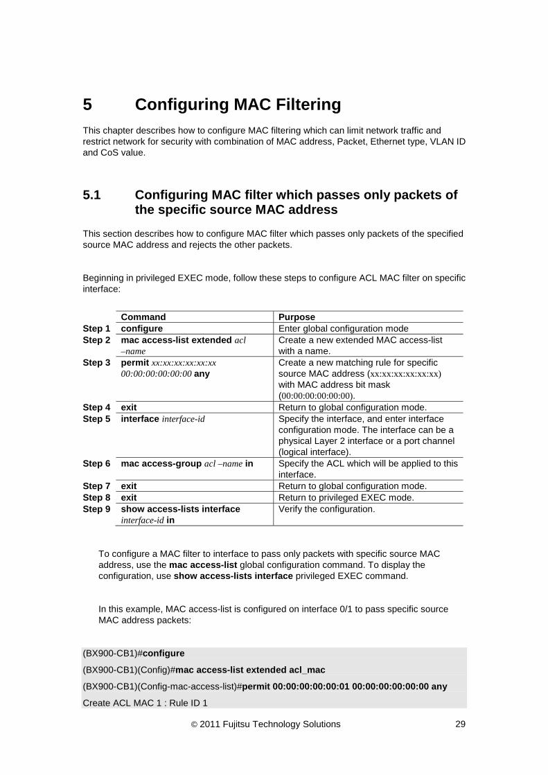
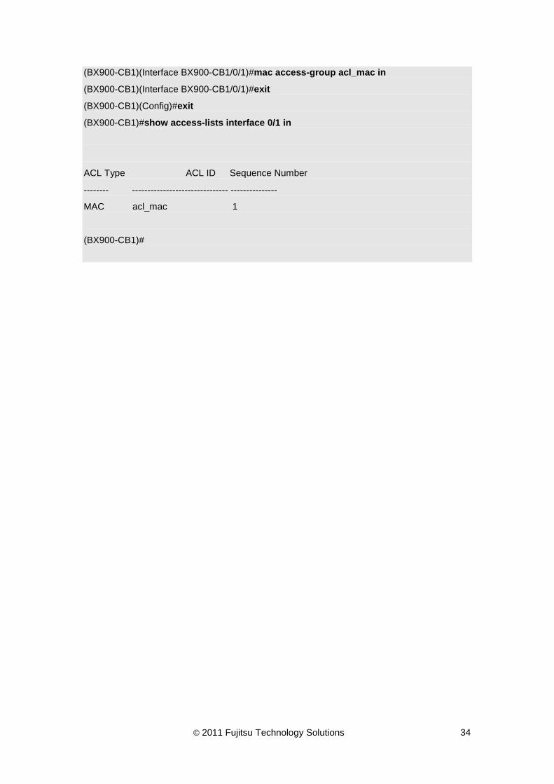
To configure a MAC filter to interface to pass only packets with specific source MAC address, use the mac access-list global configuration command. To display the configuration, use show access-lists interface privileged EXEC command.
In this example, MAC access-list is configured on interface 0/1 to pass specific source MAC address packets:
(BX900-CB1)#configure
(BX900-CB1)(Config)#mac access-list extended acl_mac
(BX900-CB1)(Config-mac-access-list)#permit 00:00:00:00:00:01 00:00:00:00:00:00 any
Create ACL MAC 1 : Rule ID 1

© 2011 Fujitsu Technology Solutions 30
(BX900-CB1)(Config-mac-access-list)#exit
(BX900-CB1)(Config)#interface 0/1
(BX900-CB1)(Interface BX900-CB1/0/1)#mac access-group acl_mac in
(BX900-CB1)(Interface BX900-CB1/0/1)#exit
(BX900-CB1)(Config)#exit
(BX900-CB1)#show access-lists interface 0/1 in
ACL Type ACL ID Sequence Number
-------- ------------------------------- ---------------
MAC acl_mac 1
(BX900-CB1)#

© 2011 Fujitsu Technology Solutions 31
5.2 Configuring MAC filter which passes only packets of specified destination MAC address
This section describes how to configure MAC filter which passes only packets of the specified destination MAC address and rejects the other packets.
Beginning in privileged EXEC mode, follow these steps to configure ACL MAC filter on specific interface:
Command Purpose Step 1 configure Enter global configuration mode Step 2 mac access-list extended
acl–name Create a new extended MAC access-list with a name.
Step 3 permit any xx:xx:xx:xx:xx:xx 00:00:00:00:00:00
Create a new matching rule for specific destination MAC address (xx:xx:xx:xx:xx:xx) with MAC address bit mask (00:00:00:00:00:00).
Step 4 exit Return to global configuration mode. Step 5 interface interface-id Specify the interface, and enter interface
configuration mode. The interface can be a physical Layer 2 interface or a port channel (logical interface).
Step 6 mac access-group acl –name in Specify the ACL which will be applied to this interface.
Step 7 exit Return to global configuration mode. Step 8 exit Return to privileged EXEC mode. Step 9 show access-lists interface
interface-id in Verify the configuration.
To configure a MAC filter to interface to pass only packets with specific destination MAC address, use the mac access-list global configuration command. To display the configuration, use show access-lists interface privileged EXEC command.
In this example, MAC access-list is configured on interface 0/1 to pass specific destination MAC address packets:
(BX900-CB1)#configure
(BX900-CB1)(Config)#mac access-list extended acl_dst_mac
(BX900-CB1)(Config-mac-access-list)#permit any 00:00:00:00:00:01 00:00:00:00:00:00
Create ACL MAC 1 : Rule ID 1
(BX900-CB1)(Config-mac-access-list)#exit
(BX900-CB1)(Config)#interface 0/1
(BX900-CB1)(Interface BX900-CB1/0/1)#mac access-group acl_dst_mac in
(BX900-CB1)(Interface BX900-CB1/0/1)#exit
(BX900-CB1)(Config)#exit

© 2011 Fujitsu Technology Solutions 32
(BX900-CB1)#show access-lists interface 0/1 in
ACL Type ACL ID Sequence Number
-------- ------------------------------- ---------------
MAC acl_dst_mac 1
(BX900-CB1)#

© 2011 Fujitsu Technology Solutions 33
5.3 Configuring MAC filter which rejects only packets of the specified packet format MAC address
This section describes how to configure MAC filter which rejects only the traffic between the specified destination MAC address and passes the other packets.
Beginning in privileged EXEC mode, follow these steps to configure ACL MAC filter on specific interface:
Command Purpose Step 1 configure Enter global configuration mode Step 2 mac access-list extended acl
–name Create a new extended MAC access-list with a name.
Step 3 deny any xx:xx:xx:xx:xx:xx 00:00:00:00:00:ff
Create a new matching rule for specific destination MAC address (xx:xx:xx:xx:xx:xx) with MAC address bit mask (00:00:00:00:00:ff).
Step 4 permit any any Create a new matching rule for all packets. Step 5 exit Return to global configuration mode. Step 6 interface interface-id Specify the interface, and enter interface
configuration mode. The interface can be a physical Layer 2 interface or a port channel (logical interface).
Step 7 mac access-group acl –name in Specify the ACL which will be applied to this interface.
Step 8 exit Return to global configuration mode. Step 9 exit Return to privileged EXEC mode. Step 10 show access-lists interface
interface-id in Verify the configuration.
To configure a MAC filter to interface to reject only packets with specific destination MAC address format, use the mac access-list global configuration command. To display the configuration, use show access-lists interface privileged EXEC command.
In this example, MAC access-list is configured on interface 0/1 to reject specific format of destination MAC address packets (00:00:00:00:00:01 ~ 00:00:00:00:00:ff):
(BX900-CB1)#configure
(BX900-CB1)(Config)#mac access-list extended acl_mac
(BX900-CB1)(Config-mac-access-list)#deny any 00:00:00:00:00:01 00:00:00:00:00:ff
Create ACL MAC 1 : Rule ID 1
(BX900-CB1)(Config-mac-access-list)#permit any any
Create ACL MAC 1 : Rule ID 2
(BX900-CB1)(Config-mac-access-list)#exit
(BX900-CB1)(Config)#interface 0/1
© 2011 Fujitsu Technology Solutions 34
(BX900-CB1)(Interface BX900-CB1/0/1)#mac access-group acl_mac in
(BX900-CB1)(Interface BX900-CB1/0/1)#exit
(BX900-CB1)(Config)#exit
(BX900-CB1)#show access-lists interface 0/1 in
ACL Type ACL ID Sequence Number
-------- ------------------------------- ---------------
MAC acl_mac 1
(BX900-CB1)#

© 2011 Fujitsu Technology Solutions 35
5.4 Configuring MAC filter which rejects only traffic between the specified MAC addresses in VLAN
This section describes how to configure MAC filter which rejects only the traffic between the specified MAC addresses.
Beginning in privileged EXEC mode, follow these steps to configure ACL MAC filter on specific interface:
Command Purpose Step 1 configure Enter global configuration mode Step 2 mac access-list extended acl
–name Create a new extended MAC access-list with a name.
Step 3 deny xx:xx:xx:xx:xx:xx 00:00:00:00:00:ff any vlan eq <0-4095>
Create a new matching rule for specific source MAC address (xx:xx:xx:xx:xx:xx) with MAC address bit mask (00:00:00:00:00:ff) and a specific VLAN ID.
Step 4 permit any any Create a new matching rule for all packets. Step 5 exit Return to global configuration mode. Step 6 interface interface-id Specify the interface, and enter interface
configuration mode. The interface can be a physical Layer 2 interface or a port channel (logical interface).
Step 7 mac access-group acl –name in Specify the ACL which will be applied to this interface.
Step 8 exit Return to global configuration mode. Step 9 exit Return to privileged EXEC mode. Step 10 show access-lists interface
interface-id in Verify the configuration.
To configure a MAC filter to interface to reject only packets between specific destination MAC addresses in VLAN, use the mac access-list global configuration command. To display the configuration, use show access-lists interface privileged EXEC command.
In this example, MAC access-list is configured on interface 0/1 to reject specific format of destination MAC address packets (00:00:00:00:00:01 ~ 00:00:00:00:00:ff):
(BX900-CB1)#configure
(BX900-CB1)(Config)#mac access-list extended acl_mac
(BX900-CB1)(Config-mac-access-list)# deny 00:00:00:00:00:01 00:00:00:00:00:ff any vlan eq 1
Create ACL MAC 1 : Rule ID 1
(BX900-CB1)(Config-mac-access-list)#permit any any
Create ACL MAC 1 : Rule ID 2
(BX900-CB1)(Config-mac-access-list)#exit
(BX900-CB1)(Config)#interface 0/1

© 2011 Fujitsu Technology Solutions 36
(BX900-CB1)(Interface BX900-CB1/0/1)#mac access-group acl_mac in
(BX900-CB1)(Interface BX900-CB1/0/1)#exit
(BX900-CB1)(Config)#exit
(BX900-CB1)#show access-lists interface 0/1 in
ACL Type ACL ID Sequence Number
-------- ------------------------------- ---------------
MAC acl_mac 1
(BX900-CB1)#

© 2011 Fujitsu Technology Solutions 37
5.5 Configuring MAC filter which passes only the traffic between the specified MAC addresses in VLAN
This section describes how to configure MAC filter which passes sonly the traffic between the specified MAC addresses.
Beginning in privileged EXEC mode, follow these steps to configure ACL MAC filter on specific interface:
Command Purpose Step 1 configure Enter global configuration mode Step 2 mac access-list extended acl
–name Create a new extended MAC access-list with a name.
Step 3 permit xx:xx:xx:xx:xx:xx 00:00:00:00:00:00 any vlan eq <0-4095>
Create a new matching rule for specific destination MAC address (xx:xx:xx:xx:xx:xx) with MAC address bit mask (00:00:00:00:00:00) and a specific VLAN ID.
Step 4 exit Return to global configuration mode. Step 5 interface interface-id Specify the interface, and enter interface
configuration mode. The interface can be a physical Layer 2 interface or a port channel (logical interface).
Step 6 mac access-group acl –name in Specify the ACL which will be applied to this interface.
Step 7 exit Return to global configuration mode. Step 8 exit Return to privileged EXEC mode. Step 9 show access-lists interface
interface-id in Verify the configuration.
To configure a MAC filter to interface to pass only packets between specific destination MAC addresses in VLAN, use the mac access-list global configuration command. To display the configuration, use show access-lists interface privileged EXEC command.
In this example, MAC access-list is configured on interface 0/1 to pass specific destination MAC address packets:
(BX900-CB1)#configure
(BX900-CB1)(Config)#mac access-list extended acl_mac
(BX900-CB1)(Config-mac-access-list)# permit 00:00:00:00:00:01 00:00:00:00:00:00 any vlan eq 1
Create ACL MAC 1 : Rule ID 1
(BX900-CB1)(Config-mac-access-list)#exit
(BX900-CB1)(Config)#interface 0/1
(BX900-CB1)(Interface BX900-CB1/0/1)#mac access-group acl_mac in
(BX900-CB1)(Interface BX900-CB1/0/1)#exit

© 2011 Fujitsu Technology Solutions 38
(BX900-CB1)(Config)#exit
(BX900-CB1)#show access-lists interface 0/1 in
ACL Type ACL ID Sequence Number
-------- ------------------------------- ---------------
MAC acl_mac 1
(BX900-CB1)#

© 2011 Fujitsu Technology Solutions 39
6 Configuring Static MAC Forwarding This section describes how to add MAC address to filter table. Only filtered member can access those MAC address.
Beginning in privileged EXEC mode, follow these steps to configure MAC filter on specific interface:
Command Purpose Step 1 configure Enter global configuration mode. Step 2 macfilter mac-address vlan-id Add mac-filter new rule. Step 3 interface interface-id Specify the interface, and enter interface
configuration mode. The interface can be a physical Layer 2 interface or a port channel (logical interface).
Step 4 macfilter addsrc mac-address vlan-id
Add specific interface to mac-filter.
Step 5 exit Return to global configuration mode. Step 6 exit Return to privileged EXEC mode. Step 7 show mac-addr-table static all Verify the configuration.
To configure a static MAC filter, use the macfilter global configuration command. To assign an interface to macfilter addsrc interface configuration command. To display the configuration, use show mac-addr-table static all privileged EXEC command.
In this example, create VLAN 1 MAC address 00:00:00:00:00:01 filter, and interface 0/40 is filter member:
(BX900-CB1)#configure
(BX900-CB1)(Config)#macfilter 00:00:00:00:00:01 1
(BX900-CB1)(Config)#interface 0/40
(BX900-CB1)(Interface BX900-CB1/0/40)#macfilter addsrc 00:00:00:00:00:01 1
(BX900-CB1)(Interface BX900-CB1/0/40)#exit
(BX900-CB1)(Config)#exit
(BX900-CB1)#show mac-addr-table static all
Source
MAC Address VLAN ID Port(s)
----------------- ------- -----------------------------------------
00:00:00:00:00:01 1 BX900-CB1/0/40
(BX900-CB1)#
© 2011 Fujitsu Technology Solutions 40
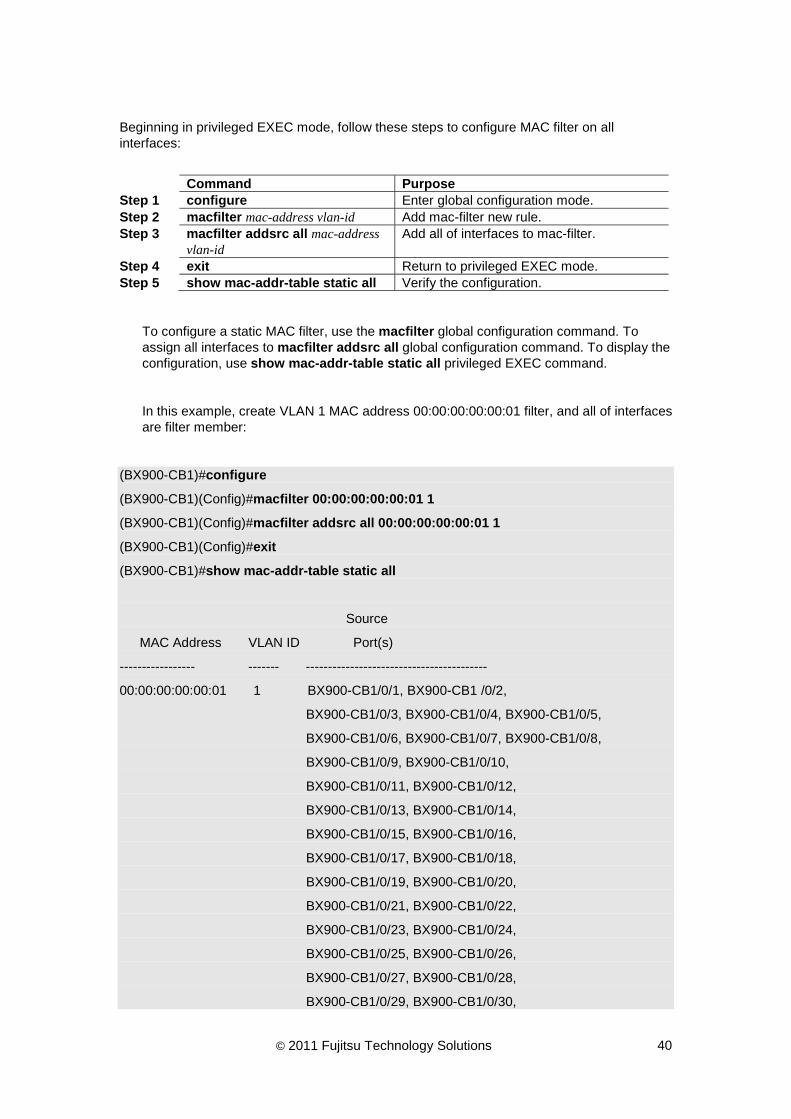
Beginning in privileged EXEC mode, follow these steps to configure MAC filter on all interfaces:
Command Purpose Step 1 configure Enter global configuration mode. Step 2 macfilter mac-address vlan-id Add mac-filter new rule. Step 3 macfilter addsrc all mac-address
vlan-id Add all of interfaces to mac-filter.
Step 4 exit Return to privileged EXEC mode. Step 5 show mac-addr-table static all Verify the configuration.
To configure a static MAC filter, use the macfilter global configuration command. To assign all interfaces to macfilter addsrc all global configuration command. To display the configuration, use show mac-addr-table static all privileged EXEC command.
In this example, create VLAN 1 MAC address 00:00:00:00:00:01 filter, and all of interfaces are filter member:
(BX900-CB1)#configure
(BX900-CB1)(Config)#macfilter 00:00:00:00:00:01 1
(BX900-CB1)(Config)#macfilter addsrc all 00:00:00:00:00:01 1
(BX900-CB1)(Config)#exit
(BX900-CB1)#show mac-addr-table static all
Source
MAC Address VLAN ID Port(s)
----------------- ------- -----------------------------------------
00:00:00:00:00:01 1 BX900-CB1/0/1, BX900-CB1 /0/2,
BX900-CB1/0/3, BX900-CB1/0/4, BX900-CB1/0/5,
BX900-CB1/0/6, BX900-CB1/0/7, BX900-CB1/0/8,
BX900-CB1/0/9, BX900-CB1/0/10,
BX900-CB1/0/11, BX900-CB1/0/12,
BX900-CB1/0/13, BX900-CB1/0/14,
BX900-CB1/0/15, BX900-CB1/0/16,
BX900-CB1/0/17, BX900-CB1/0/18,
BX900-CB1/0/19, BX900-CB1/0/20,
BX900-CB1/0/21, BX900-CB1/0/22,
BX900-CB1/0/23, BX900-CB1/0/24,
BX900-CB1/0/25, BX900-CB1/0/26,
BX900-CB1/0/27, BX900-CB1/0/28,
BX900-CB1/0/29, BX900-CB1/0/30,

© 2011 Fujitsu Technology Solutions 41
BX900-CB1/0/31, BX900-CB1/0/32,
BX900-CB1/0/33, BX900-CB1/0/34,
BX900-CB1/0/35, BX900-CB1/0/36,
BX900-CB1/0/37, BX900-CB1/0/38,
--More-- or (q)uit
Source
MAC Address VLAN ID Port(s)
----------------- ------- -----------------------------------------
00:00:00:00:00:01 1 BX900-CB1/0/39, BX900-CB1/0/40,
BX900-CB1/0/41, BX900-CB1/0/42,
BX900-CB1/0/43, BX900-CB1/0/44,
BX900-CB1/0/45, BX900-CB1/0/46,
BX900-CB1/0/47, BX900-CB1/0/48
(BX900-CB1)#

© 2011 Fujitsu Technology Solutions 42
7 Configuring QoS
7.1 Configuring priority control
This section describes how to configure priority control which assigns egress port queue of different priority to User priority value (CoS) in VLAN tag.
Beginning in privileged EXEC mode, follow these steps to configure priority control on specific interface:
Command Purpose Step 1 configure Enter global configuration mode Step 2 interface interface-id Specify the interface, and enter interface
configuration mode. The interface can be a physical Layer 2 interface or a port channel (logical interface).
Step 3 queue trust dot1p Set the trust mode to dot1p. Step 4 queue cos-map priority-id queue-id Assign a priority ID to specific traffic class
queue to configure dot1p priority mapping. Step 5 exit Return to global configuration mode. Step 6 exit Return to privileged EXEC mode. Step 7 show queue cos-map interface-id Verify the configuration.
To configure priority control and assign priority mapping to an interface, use the CoS interface configuration command. To display the configuration, use show queue cos-map privileged EXEC command.
In this example, cos-map is configured on interface 0/1 to assigns egress port queue of different priority to User priority value (CoS) in VLAN tag:
(BX900-CB1)#configure
(BX900-CB1)(Config)#interface 0/1
(BX900-CB1)(Interface BX900-CB1/0/1)#queue trust dot1p
(BX900-CB1)(Interface BX900-CB1/0/1)#queue cos-map 0 1
(BX900-CB1)(Interface BX900-CB1/0/1)#queue cos-map 1 2
(BX900-CB1)(Interface BX900-CB1/0/1)#queue cos-map 4 2
(BX900-CB1)(Interface BX900-CB1/0/1)#exit
(BX900-CB1)(Config)#exit
(BX900-CB1)#show queue cos-map 0/1

© 2011 Fujitsu Technology Solutions 43
User Priority Traffic Class
------------- -------------
0 1
1 2
2 0
3 1
4 2
5 2
6 3
7 3
(BX900-CB1)#

© 2011 Fujitsu Technology Solutions 44
7.2 Configuring priority control rewrite
This section describes how to configure priority control rewrite which rewrites priority control information of packets specified with combination of MAC address, packet format, Ethernet type, VLAN ID and CoS value.
7.2.1 IP Precedence value rewrite
This section describes how to configure IP precedence value rewrite which rewrites IP precedence value of packets which has the specified CoS value in the specified port in VLAN.
Beginning in privileged EXEC mode, follow these steps to configure IP precedence value rewrite on specific interface:
Command Purpose Step 1 configure Enter global configuration mode Step 2 diffserv Enable DiffServ Admin mode. Step 3 class-map match-all
class-map-name Create a DiffServ class with a class-map name and enter the class map mode.
Step 4 match cos <0-7> Configure a match condition based on a CoS value.
Step 5 exit Return to global configuration mode. Step 6 policy-map policy-name in Create a DiffServ policy with a policy-map
name. Step 7 class class-map-name Attach the DiffServ class to this policy. Step 8 mark ip-precedence <0-7> Configure marking action on the specific IP
precedence value. Step 9 exit Return to policy-map configuration mode. Step 10 exit Return to global configuration mode. Step 11 interface interface-id Specify the interface, and enter interface
configuration mode. The interface can be a physical Layer 2 interface or a port channel (logical interface).
Step 12 service-policy in policy-map-name Specify the policy which will be applied to this interface.
Step 13 exit Return to global configuration mode. Step 14 exit Return to privileged EXEC mode. Step 15 show class-map Verify the configuration. Step 16 show policy-map Verify the configuration. Step 17 show policy-map interface
interface-id in Verify the configuration.
To configure an IP precedence rewrite to interface, use the DiffServ configuration command. To display the policy configuration, use show policy-map privileged EXEC command. To display the class configuration, use show class-map privileged EXEC command.
© 2011 Fujitsu Technology Solutions 45
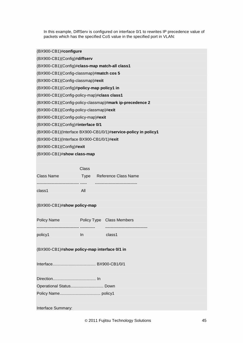
In this example, DiffServ is configured on interface 0/1 to rewrites IP precedence value of packets which has the specified CoS value in the specified port in VLAN:
(BX900-CB1)#configure
(BX900-CB1)(Config)#diffserv
(BX900-CB1)(Config)#class-map match-all class1
(BX900-CB1)(Config-classmap)#match cos 5
(BX900-CB1)(Config-classmap)#exit
(BX900-CB1)(Config)#policy-map policy1 in
(BX900-CB1)(Config-policy-map)#class class1
(BX900-CB1)(Config-policy-classmap)#mark ip-precedence 2
(BX900-CB1)(Config-policy-classmap)#exit
(BX900-CB1)(Config-policy-map)#exit
(BX900-CB1)(Config)#interface 0/1
(BX900-CB1)(Interface BX900-CB1/0/1)#service-policy in policy1
(BX900-CB1)(Interface BX900-CB1/0/1)#exit
(BX900-CB1)(Config)#exit
(BX900-CB1)#show class-map
Class
Class Name Type Reference Class Name
------------------------------- ----- -------------------------------
class1 All
(BX900-CB1)#show policy-map
Policy Name Policy Type Class Members
------------------------------- ----------- -------------------------------
policy1 In class1
(BX900-CB1)#show policy-map interface 0/1 in
Interface...................................... BX900-CB1/0/1
Direction...................................... In
Operational Status............................. Down
Policy Name.................................... policy1
Interface Summary:

© 2011 Fujitsu Technology Solutions 46
Class Name..................................... class1
In Offered Packets............................. 0
In Discarded Packets........................... 0
(BX900-CB1)#
© 2011 Fujitsu Technology Solutions 47
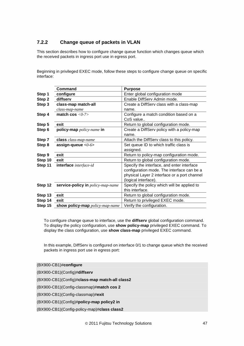
7.2.2 Change queue of packets in VLAN
This section describes how to configure change queue function which changes queue which the received packets in ingress port use in egress port.
Beginning in privileged EXEC mode, follow these steps to configure change queue on specific interface:
Command Purpose Step 1 configure Enter global configuration mode Step 2 diffserv Enable DiffServ Admin mode. Step 3 class-map match-all
class-map-name Create a DiffServ class with a class-map name.
Step 4 match cos <0-7> Configure a match condition based on a CoS value..
Step 5 exit Return to global configuration mode. Step 6 policy-map policy-name in Create a DiffServ policy with a policy-map
name. Step 7 class class-map-name Attach the DiffServ class to this policy. Step 8 assign-queue <0-6> Set queue ID to which traffic class is
assigned. Step 9 exit Return to policy-map configuration mode. Step 10 exit Return to global configuration mode. Step 11 interface interface-id Specify the interface, and enter interface
configuration mode. The interface can be a physical Layer 2 interface or a port channel (logical interface).
Step 12 service-policy in policy-map-name Specify the policy which will be applied to this interface.
Step 13 exit Return to global configuration mode. Step 14 exit Return to privileged EXEC mode. Step 15 show policy-map policy-map-name Verify the configuration.
To configure change queue to interface, use the diffserv global configuration command. To display the policy configuration, use show policy-map privileged EXEC command. To display the class configuration, use show class-map privileged EXEC command.
In this example, DiffServ is configured on interface 0/1 to change queue which the received packets in ingress port use in egress port:
(BX900-CB1)#configure
(BX900-CB1)(Config)#diffserv
(BX900-CB1)(Config)#class-map match-all class2
(BX900-CB1)(Config-classmap)#match cos 2
(BX900-CB1)(Config-classmap)#exit
(BX900-CB1)(Config)#policy-map policy2 in
(BX900-CB1)(Config-policy-map)#class class2

© 2011 Fujitsu Technology Solutions 48
(BX900-CB1)(Config-policy-classmap)#assign-queue 7
(BX900-CB1)(Config-policy-classmap)#exit
(BX900-CB1)(Config-policy-map)#exit
(BX900-CB1)(Config)#interface 0/1
(BX900-CB1)(Interface BX900-CB1/0/1)#service-policy in policy2
(BX900-CB1)(Interface BX900-CB1/0/1)#exit
(BX900-CB1)(Config)#exit
(BX900-CB1)#show class-map
Class
Class Name Type Reference Class Name
------------------------------- ----- -------------------------------
class1 All
class2 All
(BX900-CB1)#show policy-map
Policy Name Policy Type Class Members
------------------------------- ----------- -------------------------------
policy1 In class1
policy2 In class2
(BX900-CB1)#show policy-map policy2
Policy Name.................................... policy2
Policy Type.................................... In
Class Name..................................... class2
Assign Queue................................... 7
(BX900-CB1)#

© 2011 Fujitsu Technology Solutions 49
8 Configuring Spanning Tree This chapter describes how to configure Spanning Tree protocol.
8.1 Configuring Spanning Tree Mode
This section describes how to configure spanning tree mode. MSTP, RSTP and STP are supported in current firmware.
Beginning in privileged EXEC mode, follow these steps to specify the spanning tree mode and enable the spanning tree for the system.
Command Purpose Step 1 configure Enter global configuration mode. Step 2 spanning-tree mode {stp | rstp |
mstp} To specify the spanning tree protocol.
Step 3 spanning-tree Enable the spanning tree admin mode. Step 4 spanning-tree port mode all Enable the spanning tree for all interfaces.Step 5 exit Return to privileged EXEC mode. Step 6 show spanning-tree summary Verify the configuration.
To specify the spanning tree mode, use spanning-tree mode global configuration command. To enable spanning tree, use spanning-tree global configuration command. To enable interface mode, use spanning-tree port mode all global configuration command or use spanning-tree port mode interface configuration command. To display settings and parameters for the spanning tree, use show spanning-tree summary privileged EXEC command.
In this example, we configure to use RSTP for the system and enable spanning tree for all interfaces.
(BX900-CB1)#configure
(BX900-CB1)(Config)#spanning-tree mode rstp
(BX900-CB1)(Config)#spanning-tree
(BX900-CB1)(Config)#spanning-tree port mode all
(BX900-CB1)(Config)#exit
(BX900-CB1)#show spanning-tree summary
Spanning Tree Adminmode........... Enabled
Spanning Tree Forward BPDU........ Enabled
Spanning Tree Version............. IEEE 802.1w

© 2011 Fujitsu Technology Solutions 50
Configuration Name................ 00-1E-68-85-F7-5F
Configuration Revision Level...... 0
Configuration Digest Key.......... 0xac36177f50283cd4b83821d8ab26de62
Configuration Format Selector..... 0
No MST instances to display.
(BX900-CB1)#show spanning-tree mst port summary 0 all
STP STP Port
Interface Mode Type State Role
----------------- -------- ------- ----------------- ----------
BX900-CB1/0/1 Enabled Disabled Disabled
BX900-CB1/0/2 Enabled Disabled Disabled
BX900-CB1/0/3 Enabled Disabled Disabled
BX900-CB1/0/4 Enabled Disabled Disabled
BX900-CB1/0/5 Enabled Disabled Disabled
BX900-CB1/0/6 Enabled Disabled Disabled
BX900-CB1/0/7 Enabled Disabled Disabled
BX900-CB1/0/8 Enabled Disabled Disabled
BX900-CB1/0/9 Enabled Disabled Disabled
BX900-CB1/0/10 Enabled Disabled Disabled
BX900-CB1/0/11 Enabled Disabled Disabled
BX900-CB1/0/12 Enabled Disabled Disabled
BX900-CB1/0/13 Enabled Disabled Disabled
BX900-CB1/0/14 Enabled Disabled Disabled
BX900-CB1/0/15 Enabled Disabled Disabled
BX900-CB1/0/16 Enabled Disabled Disabled
BX900-CB1/0/17 Enabled Disabled Disabled
BX900-CB1/0/18 Enabled Disabled Disabled
BX900-CB1/0/19 Enabled Disabled Disabled
--More-- or (q)uit
BX900-CB1/0/20 Enabled Disabled Disabled
BX900-CB1/0/21 Enabled Disabled Disabled
BX900-CB1/0/22 Enabled Disabled Disabled
BX900-CB1/0/23 Enabled Disabled Disabled
BX900-CB1/0/24 Enabled Disabled Disabled
BX900-CB1/0/25 Enabled Disabled Disabled
BX900-CB1/0/26 Enabled Disabled Disabled

© 2011 Fujitsu Technology Solutions 51
BX900-CB1/0/27 Enabled Disabled Disabled
BX900-CB1/0/28 Enabled Disabled Disabled
BX900-CB1/0/29 Enabled Disabled Disabled
BX900-CB1/0/30 Enabled Disabled Disabled
BX900-CB1/0/31 Enabled Disabled Disabled
BX900-CB1/0/32 Enabled Disabled Disabled
BX900-CB1/0/33 Enabled Disabled Disabled
BX900-CB1/0/34 Enabled Disabled Disabled
BX900-CB1/0/35 Enabled Disabled Disabled
BX900-CB1/0/36 Enabled Disabled Disabled
BX900-CB1/0/37 Enabled Disabled Disabled
BX900-CB1/0/38 Enabled Disabled Disabled
BX900-CB1/0/39 Enabled Disabled Disabled
BX900-CB1/0/40 Enabled Disabled Disabled
BX900-CB1/0/41 Enabled Disabled Disabled
BX900-CB1/0/42 Enabled Disabled Disabled
--More-- or (q)uit
BX900-CB1/0/43 Enabled Disabled Disabled
BX900-CB1/0/44 Enabled Disabled Disabled
BX900-CB1/0/45 Enabled Disabled Disabled
BX900-CB1/0/46 Enabled Disabled Disabled
BX900-CB1/0/47 Enabled Forwarding Root
BX900-CB1/0/48 Enabled Disabled Disabled
(BX900-CB1)#

© 2011 Fujitsu Technology Solutions 52
8.2 Configuring MSTP
This section describes how to configure MSTP. MSTP can handle frames per VLAN.
Beginning in privileged EXEC mode, follow these steps to specify the MSTP configuration and enable MSTP.
Command Purpose Step 1 configure Enter global configuration mode. Step 2 spanning-tree mst instance
instance-id Add a MSTP instance to the switch.
Step 3 spanning-tree configuration name Set the MSTP region name. Step 4 spanning-tree configuration
revision Set the MSTP configuration revision number.
Step 5 spanning-tree mst vlan instance-id vlan-id
Add an association between a MSTP instance and a VLAN.
Step 6 spanning-tree mode mstp Set the Force Protocol Version parameter to MSTP.
Step 7 spanning-tree Set the spanning-tree operational mode to be enabled.
Step 8 exit Return to global configuration mode.
To add a multiple spanning tree instance to the switch, use spanning-tree mst instance global configuration command. To add an association between a multiple spanning tree instance and a VLAN, use spanning-tree mst vlan global configuration command. To set the MSTP region name and revision number, use spanning-tree configuration name and spanning-tree configuration revision global configuration command.
To display settings and parameters for the specified multiple spanning tree instance, use show spanning-tree mst detailed privileged EXEC command.
To display configuration for the MSTP, use show spanning-tree summary privileged EXEC command.
In this example, a multiple spanning tree instance 2 is added to the switch and associated with VLAN 100.
(BX900-CB1)#configure
(BX900-CB1)(Config)#spanning-tree mst instance 2
(BX900-CB1)(Config)#spanning-tree configuration name FSC
(BX900-CB1)(Config)#spanning-tree configuration revision 2
(BX900-CB1)(Config)#spanning-tree mst vlan 2 100
(BX900-CB1)(Config)#spanning-tree mode mstp
(BX900-CB1)(Config)#spanning-tree
(BX900-CB1)(Config)#exit

© 2011 Fujitsu Technology Solutions 53
(BX900-CB1)#show spanning-tree mst detailed 2
MST Instance ID................................ 2
MST Bridge Priority............................ 32768
MST Bridge Identifier.......................... F0:02:00:1E:68:C6:06:0C
Time Since Topology Change..................... 0 day 0 hr 43 min 49 sec
Topology Change Count.......................... 1
Topology Change in progress.................... FALSE
Designated Root................................ F0:02:00:1E:68:C6:06:0C
Root Path Cost................................. 0
Root Port Identifier........................... 00:00
Associated FIDs Associated VLANs
--------------- ----------------
100 100
(BX900-CB1)#show spanning-tree summary
Spanning Tree Adminmode........... Enabled
Spanning Tree Forward BPDU........ Enabled
Spanning Tree Version............. IEEE 802.1s
Configuration Name................ FSC
Configuration Revision Level...... 2
Configuration Digest Key.......... 0xe1dd2d16f2958ee5b41cde578b6d2336
Configuration Format Selector..... 0
MST Instances..................... 2
!
Be careful when using the revision command to set the MST configuration revision level because a mistake can put the switch in a different region.

© 2011 Fujitsu Technology Solutions 54
9 Configuring IGMP snooping & Querier This section describes how to configure the IGMP snooping.
9.1 Configuring IGMP snooping by interface
This section describes how to configure IGMP snooping on a specific interface.
Beginning in privileged EXEC mode, follow these steps to configure IGMP snooping on a specific interface:
Command Purpose Step 1 configure Enter global configuration mode. Step 2 ip igmp snooping Enable IGMP snooping admin mode. Step 3 interface interface-id Specify the interface, and enter interface
configuration mode. The interface can be a physical Layer 2 interface or a port channel (logical interface).
Step 4 ip igmp snooping interfacemode
Enable IGMP snooping on a specific interface.
Step 5 ip igmp snooping groupmembershipinterval <2-3600>
Setting multicast member timeout interval. If specific interface never update group info during groupmembershipinterval, it will be remove from multicast group member (dynamic member).
Step 6 ip igmp snooping max-response-time <1-3599>
Setting multicast member remove interval. If specific interface receive IGMP leave packets, it will not remove this multicast group during max-response-time. IGMP fast leave must be disabled.
Step 7 ip igmp snooping fast-leave Enable IGMP snooping fast leave mode. Step 8 ip igmp snooping
mcrtrexpiretime <0-3600> Setting multicast router timeout interval. If specific interface never receive IGMP query packet during Multicast Router Present Expiration time, it will be remove from multicast router port (dynamic router).
Step 9 exit Return to global configuration mode. Step 10 exit Return to privileged EXEC mode. Step 11 show ip igmp snooping
interface-id Verify the configuration.
To enable/disable the IGMP snooping on a switch, use ip igmp snooping/no ip igmp snooping global configuration command. To enable IGMP snooping on a specific interface, use ip igmp snooping interfacemode interface configuration command. To display the IGMP snooping configuration for a specific interface, use show ip igmp snooping interface interface-id privileged EXEC command.
© 2011 Fujitsu Technology Solutions 55
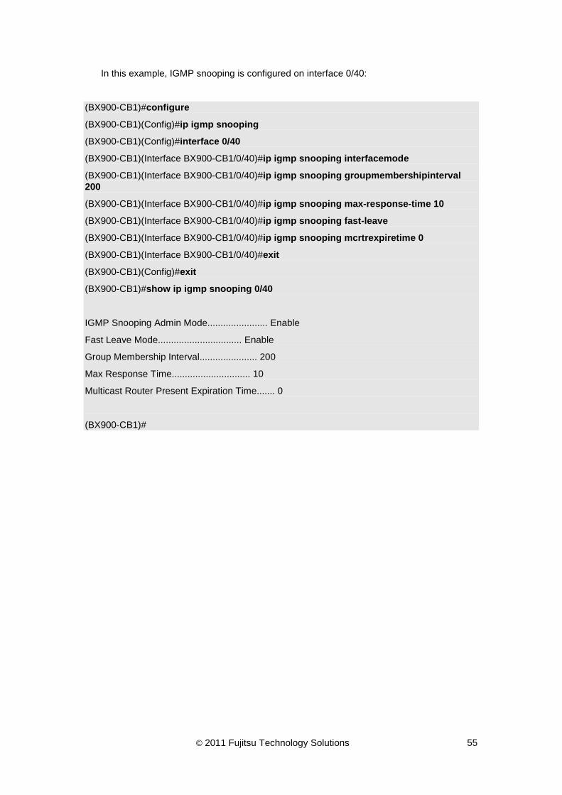
In this example, IGMP snooping is configured on interface 0/40:
(BX900-CB1)#configure
(BX900-CB1)(Config)#ip igmp snooping
(BX900-CB1)(Config)#interface 0/40
(BX900-CB1)(Interface BX900-CB1/0/40)#ip igmp snooping interfacemode
(BX900-CB1)(Interface BX900-CB1/0/40)#ip igmp snooping groupmembershipinterval 200
(BX900-CB1)(Interface BX900-CB1/0/40)#ip igmp snooping max-response-time 10
(BX900-CB1)(Interface BX900-CB1/0/40)#ip igmp snooping fast-leave
(BX900-CB1)(Interface BX900-CB1/0/40)#ip igmp snooping mcrtrexpiretime 0
(BX900-CB1)(Interface BX900-CB1/0/40)#exit
(BX900-CB1)(Config)#exit
(BX900-CB1)#show ip igmp snooping 0/40
IGMP Snooping Admin Mode....................... Enable
Fast Leave Mode................................ Enable
Group Membership Interval...................... 200
Max Response Time.............................. 10
Multicast Router Present Expiration Time....... 0
(BX900-CB1)#

© 2011 Fujitsu Technology Solutions 56
Beginning in privileged EXEC mode, follow these steps to configure IGMP snooping on all interfaces:
Command Purpose Step 1 configure Enter global configuration mode. Step 2 ip igmp snooping Enable IGMP snooping admin mode. Step 3 ip igmp snooping
interfacemode all Enable IGMP snooping on all interfaces.
Step 4 ip igmp snooping groupmembershipinterval <2-3600>
Setting multicast member timeout interval. If specific interface never update group info during groupmembershipinterval, it will be remove from multicast group member (dynamic member).
Step 5 ip igmp snooping max-response-time <1-3599>
Setting multicast member remove interval. If specific interface receive IGMP leave packets, it will not remove this multicast group during max-response-time. IGMP fast leave must be disabled.
Step 6 no ip igmp snooping fast-leave Disable IGMP Snooping fast leave mode. Step 7 ip igmp snooping
mcrtrexpiretime <0-3600> Setting multicast router timeout interval. If specific interface never receive IGMP query packet during Multicast Router Present Expiration time, it will be remove from multicast router port (dynamic router).
Step 8 exit Return to privileged EXEC mode. Step 9 show ip igmp snooping Verify the configuration.
In this example, IGMP Snooping is configured on all interfaces:
(BX900-CB1)#configure
(BX900-CB1)(Config)#ip igmp snooping
(BX900-CB1)(Config)#ip igmp snooping interfacemode all
(BX900-CB1)(Config)#ip igmp snooping groupmembershipinterval 260
(BX900-CB1)(Config)#ip igmp snooping max-response-time 10
(BX900-CB1)(Config)#no ip igmp snooping fast-leave
(BX900-CB1)(Config)#ip igmp snooping mcrtrexpiretime 0
(BX900-CB1)(Config)#exit
(BX900-CB1)#show ip igmp snooping
Admin Mode..................................... Enable
Multicast Control Frame Count.................. 0
Interfaces Enabled for IGMP Snooping........... BX900-CB1/0/1
BX900-CB1/0/2
BX900-CB1/0/3
BX900-CB1/0/4
BX900-CB1/0/5

© 2011 Fujitsu Technology Solutions 57
BX900-CB1/0/6
BX900-CB1/0/7
BX900-CB1/0/8
BX900-CB1/0/9
BX900-CB1/0/10
BX900-CB1/0/11
BX900-CB1/0/12
BX900-CB1/0/13
BX900-CB1/0/14
BX900-CB1/0/15
BX900-CB1/0/16
BX900-CB1/0/17
BX900-CB1/0/18
BX900-CB1/0/19
BX900-CB1/0/20
--More-- or (q)uit
BX900-CB1/0/21
BX900-CB1/0/22
BX900-CB1/0/23
BX900-CB1/0/24
BX900-CB1/0/25
BX900-CB1/0/26
BX900-CB1/0/27
BX900-CB1/0/28
BX900-CB1/0/29
BX900-CB1/0/30
BX900-CB1/0/31
BX900-CB1/0/32
BX900-CB1/0/33
BX900-CB1/0/34
BX900-CB1/0/35
BX900-CB1/0/36
BX900-CB1/0/37
BX900-CB1/0/38
BX900-CB1/0/39
BX900-CB1/0/40
BX900-CB1/0/41
BX900-CB1/0/42

© 2011 Fujitsu Technology Solutions 58
BX900-CB1/0/43
--More-- or (q)uit
BX900-CB1/0/44
BX900-CB1/0/45
BX900-CB1/0/46
BX900-CB1/0/47
BX900-CB1/0/48
Vlans enabled for IGMP snooping................ None
(BX900-CB1)#

© 2011 Fujitsu Technology Solutions 59
9.2 Configuring IGMP snooping by VLAN
This section describes how to configure IGMP snooping on specific VLAN.
Beginning in privileged EXEC mode, follow these steps to configure IGMP snooping on specific VLAN:
Command Purpose Step 1 configure Enter global configuration mode. Step 2 ip igmp snooping Enable IGMP snooping admin mode. Step 3 vlan database Enter VLAN configuration mode. Step 4 set igmp vlan-id Enable IGMP snooping on a specific VLAN. Step 5 set igmp
groupmembership-interval vlan-id <2-3600>
Setting multicast member timeout interval. If specific interface never update group info during groupmembership-interval, it will be remove from multicast group member (dynamic member).
Step 6 set igmp maxresponse vlan-id <1-3599>
Setting multicast member remove interval. If specific interface receive IGMP leave packets, it will not remove this multicast group during maxresponse. IGMP fast leave must be disabled.
Step 7 set igmp fast-leave vlan-id Enable IGMP snooping fast leave mode. Step 8 set igmp mcrtrexpiretime vlan-id
<0-3600> Setting multicast router timeout interval. If specific interface never receive IGMP query packet during Multicast Router Present Expiration time, it will be remove from multicast router port (dynamic router).
Step 9 exit Return to global configuration mode. Step 10 exit Return to privileged EXEC mode. Step 11 show ip igmp snooping vlan-id Verify the configuration.
To enable/disable the IGMP snooping on a switch, use ip igmp snooping/no ip igmp snooping global configuration command. To enable IGMP snooping on a specific VLAN, use set igmp vlan-id VLAN configuration command. To display the IGMP snooping configuration for a specific VLAN, use show ip igmp snooping vlan-id privileged EXEC command.
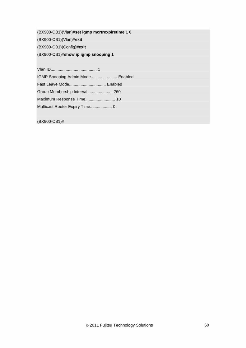
In this example, IGMP Snooping is configured on VLAN 1:
(BX900-CB1)#configure
(BX900-CB1)(Config)#ip igmp snooping
(BX900-CB1)(Config)#vlan database
(BX900-CB1)(Vlan)#set igmp 1
(BX900-CB1)(Vlan)#set igmp groupmembership-interval 1 260
(BX900-CB1)(Vlan)#set igmp maxresponse 1 10
(BX900-CB1)(Vlan)#set igmp fast-leave 1
© 2011 Fujitsu Technology Solutions 60
(BX900-CB1)(Vlan)#set igmp mcrtrexpiretime 1 0
(BX900-CB1)(Vlan)#exit
(BX900-CB1)(Config)#exit
(BX900-CB1)#show ip igmp snooping 1
Vlan ID........................................ 1
IGMP Snooping Admin Mode....................... Enabled
Fast Leave Mode................................ Enabled
Group Membership Interval...................... 260
Maximum Response Time.......................... 10
Multicast Router Expiry Time................... 0
(BX900-CB1)#

© 2011 Fujitsu Technology Solutions 61
9.3 Configuring IGMP snooping static router port
This section describes how to configure IGMP snooping static router port.
Beginning in privileged EXEC mode, follow these steps to configure IGMP snooping static router port on specific interface:
Command Purpose Step 1 configure Enter global configuration mode. Step 2 ip igmp snooping Enable IGMP snooping admin mode. Step 3 interface interface-id Specify the interface, and enter interface
configuration mode. The interface can be a physical Layer 2 interface or a port channel (logical interface).
Step 4 ip igmp snooping mrouter interface
Setting IGMP snooping static router port on specific interface.
Step 5 exit Return to global configuration mode. Step 6 exit Return to privileged EXEC mode. Step 7 show ip igmp snooping mrouter
interface interface-id Verify the configuration.
To enable/disable the IGMP snooping on a switch, use ip igmp snooping/no ip igmp snooping global configuration command. To set IGMP snooping static router port on a specific interface, use ip igmp snooping mrouter interface interface configuration command. To display the IGMP snooping static router port for a specific interface, use show ip igmp snooping mrouter interface privileged EXEC command.
In this example, interface 0/40 is configured to be a static router port:
(BX900-CB1)#configure
(BX900-CB1)(Config)#ip igmp snooping
(BX900-CB1)(Config)#interface 0/40
(BX900-CB1)(Interface BX900-CB1/0/40)#ip igmp snooping mrouter interface
(BX900-CB1)(Interface BX900-CB1/0/40)#exit
(BX900-CB1)(Config)#exit
(BX900-CB1)#show ip igmp snooping mrouter interface 0/40
Slot/Port…................................... BX900-CB1/0/40
Multicast Router Attached…................... Enable
(BX900-CB1)#

© 2011 Fujitsu Technology Solutions 62
Beginning in privileged EXEC mode, follow these steps to configure IGMP snooping static router port on specific VLAN:
Command Purpose Step 1 configure Enter global configuration mode. Step 2 ip igmp snooping Enable IGMP snooping admin mode. Step 3 interface interface-id Specify the interface, and enter interface
configuration mode. The interface can be a physical Layer 2 interface or a port channel (logical interface).
Step 4 ip igmp snooping mrouter vlan-id
Setting IGMP snooping static router port on specific VLAN.
Step 5 exit Return to global configuration mode. Step 6 exit Return to privileged EXEC mode. Step 7 show ip igmp snooping mrouter
vlan-id Verify the configuration.
To enable/disable the IGMP snooping on a switch, use ip igmp snooping/no ip igmp snooping global configuration command. To set IGMP snooping static router port on a specific VLAN for a specific interface, use ip igmp snooping mrouter interface configuration command. To display the IGMP snooping static router port for a specific interface, use show ip igmp snooping mrouter vlan privileged EXEC command.
In this example, VLAN 1, interface 0/40 is configured to static router port:
(BX900-CB1)#configure
(BX900-CB1)(Config)#ip igmp snooping
(BX900-CB1)(Config)#interface 0/40
(BX900-CB1)(Interface BX900-CB1/0/40)#ip igmp snooping mrouter 1
(BX900-CB1)(Interface BX900-CB1/0/40)#exit
(BX900-CB1)(Config)#exit
(BX900-CB1)#show ip igmp snooping mrouter vlan 0/40
Slot/Port...................................... BX900-CB1/0/40
VLAN ID
--------
1
(BX900-CB1)#

© 2011 Fujitsu Technology Solutions 63
9.4 Configuring IGMP snooping static group member
This section describes how to configure IGMP snooping static group member.
Beginning in privileged EXEC mode, follow these steps to configure IGMP snooping static group member on specific interface:
Command Purpose Step 1 configure Enter global configuration mode. Step 2 ip igmp snooping Enable IGMP snooping admin mode. Step 3 ip igmp snooping
interfacemode all Enable IGMP snooping interface mode.
Step 4 ip igmp snooping static mac-addr vlan vlan-id interface interface-id
Setting IGMP snooping static group member on specific interface.
Step 5 exit Return to privileged EXEC mode. Step 6 show ip igmp snooping static Verify the configuration.
To enable/disable the IGMP snooping on a switch, use ip igmp snooping/no ip igmp snooping global configuration command. To set IGMP snooping static group member on a specific interface, use ip igmp snooping static mac-addr vlan vlan-id interface interface-id interface configuration command. To display the IGMP snooping static router port for a specific interface, use show ip igmp snooping static privileged EXEC command.
In this example, interface 0/40 is configured to static group member:
(BX900-CB1)#configure
(BX900-CB1)(Config)#ip igmp snooping
(BX900-CB1)(Config)#ip igmp snooping interfacemode all
(BX900-CB1)(Config)#ip igmp snooping static 01:00:5e:11:11:11 vlan 1 interface 0/40
(BX900-CB1)(Config)#exit
(BX900-CB1)#show ip igmp snooping static
VLAN MAC Address Port State
==== ================= ================= ======
1 01:00:5e:11:11:11 BX900-CB1/0/40 Act.
(BX900-CB1)#

© 2011 Fujitsu Technology Solutions 64
9.5 Configuring IGMP Snooping Querier by VLAN
This section describes how to configure IGMP snooping querier.
Beginning in privileged EXEC mode, follow these steps to configure IGMP snooping querier on specific VLAN:
Command Purpose Step 1 configure Enter global configuration mode. Step 2 ip igmp snooping querier Enable IGMP snooping querier admin
mode. Step 3 ip igmp snooping querier
version <1-2> Setting IGMP snooping querier version.
Step 4 ip igmp snooping querier vlan vlan-id
Enable IGMP snooping querier on specific VLAN.
Step 5 ip igmp snooping querier vlan vlan-id address ip-address
Setting IGMP snooping querier IP address on specific VLAN.
Step 6 ip igmp snooping querier vlan vlan-id election-participate
Enable IGMP snooping querier election participate mode.
Step 7 exit Return to privileged EXEC mode. Step 8 show ip igmp snooping querier Verify the IGMP snooping querier
configuration. Step 9 show ip igmp snooping querier
vlan vlan-id Verify the IGMP snooping querier VLAN configuration.
To enable/disable the IGMP snooping querier on a switch, use ip igmp snooping querier/no ip igmp snooping querier global configuration command. To set IGMP snooping querier version, use ip igmp snooping querier version global configuration command. To enable/disable IGMP snooping querier on a specific VLAN, use ip igmp snooping querier vlan / no ip igmp snooping querier vlan global configuration command. To display the IGMP snooping querier, use show ip igmp snooping querier or show ip igmp snooping querier vlan privileged EXEC command.
In this example, VLAN 1 is configured to enable IGMP snooping querier:
(BX900-CB1)#configure
(BX900-CB1)(Config)#ip igmp snooping querier
(BX900-CB1)(Config)#ip igmp snooping querier version 2
(BX900-CB1)(Config)#ip igmp snooping querier vlan 1
(BX900-CB1)(Config)#ip igmp snooping querier vlan 1 address 192.168.2.1
(BX900-CB1)(Config)#ip igmp snooping querier vlan 1 election-participate
(BX900-CB1)(Config)#exit
(BX900-CB1)#show ip igmp snooping querier
Global IGMP Snooping querier status
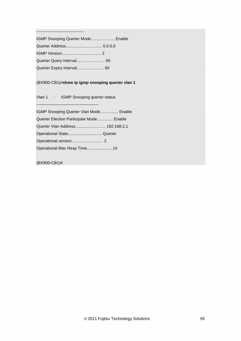
© 2011 Fujitsu Technology Solutions 65
-----------------------------------
IGMP Snooping Querier Mode..................... Enable
Querier Address................................ 0.0.0.0
IGMP Version................................... 2
Querier Query Interval......................... 60
Querier Expiry Interval........................ 60
(BX900-CB1)#show ip igmp snooping querier vlan 1
Vlan 1 : IGMP Snooping querier status
----------------------------------------------
IGMP Snooping Querier Vlan Mode................ Enable
Querier Election Participate Mode.............. Enable
Querier Vlan Address........................... 192.168.2.1
Operational State.............................. Querier
Operational version............................ 2
Operational Max Resp Time...................... 10
(BX900-CB1)#

© 2011 Fujitsu Technology Solutions 66
10 Configuring MLD Snooping & Querier This chapter describes how to configure the MLD snooping.
10.1 Configuring MLD Snooping by interface
This section describes how to configure MLD snooping on specific port.
Beginning in privileged EXEC mode, follow these steps to configure MLD snooping on specific interface:
Command Purpose Step 1 configure Enter global configuration mode. Step 2 ipv6 mld snooping Enable MLD snooping admin mode. Step 3 interface interface-id Specify the interface, and enter interface
configuration mode. The interface can be a physical Layer 2 interface or a port channel (logical interface).
Step 4 ipv6 mld snooping interfacemode
Enable MLD snooping on specific interface.
Step 5 ipv6 mld snooping groupmembership-interval <2-3600>
Setting multicast member timeout interval. If specific interface never update group info during group membership-interval, it will be remove from multicast group member (dynamic member).
Step 6 ipv6 mld snooping max-response-time <1-3599>
Setting multicast member remove interval. If specific interface receive MLD leave packets, it will not remove this multicast group during max-response-time. MLD fast leave must be disabled.
Step 7 ipv6 mld snooping fast-leave Enable MLD snooping fast leave mode. Step 8 ipv6 mld snooping
mcrtrexpiretime <0-3600> Setting multicast router timeout interval. If specific interface never receive MLD query packet during Multicast Router Present Expiration time, it will be remove from multicast router port (dynamic router).
Step 9 exit Return to global configuration mode. Step 10 exit Return to privileged EXEC mode. Step 11 show ipv6 mld snooping Verify the configuration.
To enable/disable the MLD snooping on a switch, use ipv6 mld snooping/no ipv6 mld snooping global configuration command. To enable/disable MLD snooping for a specific interface, use ipv6 mld snooping interfacemode/no ipv6 mld snooping interfacemode interface configuration command. To display the MLD snooping configuration, use show ipv6 mld snooping privileged EXEC command.
In this example, MLD snooping is configured on interface 0/40:

© 2011 Fujitsu Technology Solutions 67
(BX900-CB1)#configure
(BX900-CB1)(Config)#ipv6 mld snooping
(BX900-CB1)(Config)#interface 0/40
(BX900-CB1)(Interface BX900-CB1/0/40)#ipv6 mld snooping interfacemode
(BX900-CB1)(Interface BX900-CB1/0/40)#ipv6 mld snooping groupmembership-interval 260
(BX900-CB1)(Interface BX900-CB1/0/40)#ipv6 mld snooping max-response-time 10
(BX900-CB1)(Interface BX900-CB1/0/40)#ipv6 mld snooping fast-leave
(BX900-CB1)(Interface BX900-CB1/0/40)#ipv6 mld snooping mcrtrexpiretime 0
(BX900-CB1)(Interface BX900-CB1/0/40)#exit
(BX900-CB1)(Config)#exit
(BX900-CB1)#show ipv6 mld snooping
Admin Mode..................................... Enable
Multicast Control Frame Count.................. 0
Interfaces Enabled for MLD Snooping............ BX900-CB1/0/40
Vlans enabled for MLD snooping................. None
(BX900-CB1)#
Beginning in privileged EXEC mode, follow these steps to configure MLD snooping on all interfaces:
Command Purpose Step 1 configure Enter global configuration mode. Step 2 ipv6 mld snooping Enable MLD snooping admin mode. Step 3 ipv6 mld snooping interfacemode
all Enable MLD snooping on all interfaces.
Step 4 ipv6 mld snooping groupmembershipinterval <2-3600>
Setting multicast member timeout interval. If specific interface never update group info during group membership-interval, it will be remove from multicast group member (dynamic member).
Step 5 ipv6 mld snooping max-response-time <1-3599>
Setting multicast member remove interval. If specific interface receive MLD leave packets, it will not remove this multicast group during max-response-time. MLD fast leave must be disabled.
Step 6 ipv6 mld snooping fast-leave Enable MLD snooping fast leave mode. Step 7 ipv6 mld snooping
mcrtrexpiretime <0-3600> Setting multicast router timeout interval. If specific interface never receive MLD query packet during Multicast Router Present Expiration time, it will be remove from multicast router port (dynamic router).
Step 8 exit Return to privileged EXEC mode. Step 9 show ipv6 mld snooping Verify the configuration.

© 2011 Fujitsu Technology Solutions 68
To enable/disable the MLD snooping on all interfaces, use ipv6 mld snooping interfacemode all/no ipv6 mld snooping interfacemode all global configuration command.
In this example, MLD snooping is configured on all interfaces:
(BX900-CB1)#configure
(BX900-CB1)(Config)#ipv6 mld snooping
(BX900-CB1)(Config)#ipv6 mld snooping interfacemode all
(BX900-CB1)(Config)#ipv6 mld snooping groupmembershipinterval 260
(BX900-CB1)(Config)#ipv6 mld snooping snooping max-response-time 10
(BX900-CB1)(Config)#ipv6 mld snooping fast-leave
(BX900-CB1)(Config)#ipv6 mld snooping mcrtrexpiretime 0
(BX900-CB1)(Config)#exit
(BX900-CB1)#

© 2011 Fujitsu Technology Solutions 69
10.2 Configuring MLD Snooping by VLAN
This section describes how to configure MLD snooping on a specific VLAN.
Beginning in privileged EXEC mode, follow these steps to configure MLD snooping on specific VLAN:
Command Purpose Step 1 configure Enter global configuration mode. Step 2 ipv6 mld snooping Enable MLD snooping admin mode. Step 3 vlan database Enter VLAN configuration mode. Step 4 set mld vlan-id Enable MLD snooping on a specific VLAN. Step 5 set mld
groupmembership-interval vlan-id <2-3600>
Setting multicast member timeout interval. If specific interface never update group info during group membership-interval, it will be remove from multicast group member (dynamic member).
Step 6 set mld maxresponse vlan-id <1-3599>
Setting multicast member remove interval. If specific interface receive MLD leave packets, it will not remove this multicast group during max response. MLD fast leave must be disabled.
Step 7 set mld fast-leave vlan-id Enable MLD snooping fast leave mode. Step 8 set mld mcrtrexpiretime vlan-id
<0-3600> Setting multicast router timeout interval. If specific interface never receive MLD query packet during Multicast Router Present Expiration time, it will be remove from multicast router port (dynamic router).
Step 9 exit Return to global configuration mode. Step 10 exit Return to privileged EXEC mode. Step 11 show ipv6 mld snooping Verify the configuration.
To enable/disable the MLD snooping on a specific VLAN, use set mld vlan-id/no set mld vlan-id VLAN configuration command. To display the MLD snooping configuration, use show ipv6 mld snooping privileged EXEC command.
In this example, MLD snooping is configured on VLAN 1:
(BX900-CB1)#configure
(BX900-CB1)(Config)#ipv6 mld snooping
(BX900-CB1)(Config)#vlan database
(BX900-CB1)(Vlan)#set mld 1
(BX900-CB1)(Vlan)#set mld groupmembership-interval 1 260
(BX900-CB1)(Vlan)# set mld maxresponse 1 10
(BX900-CB1)(Vlan)#set mld fast-leave 1
(BX900-CB1)(Vlan)#set mld mcrtrexpiretime 1 0

© 2011 Fujitsu Technology Solutions 70
(BX900-CB1)(Vlan)#exit
(BX900-CB1)(Config)#exit
(BX900-CB1)#show ipv6 mld snooping
Admin Mode..................................... Enable
Multicast Control Frame Count.................. 0
Interfaces Enabled for MLD Snooping............ None
Vlans enabled for MLD snooping................. 1
(BX900-CB1)#

© 2011 Fujitsu Technology Solutions 71
10.3 Configuring MLD Snooping static router port
This section describes how to configure MLD snooping static router port.
Beginning in privileged EXEC mode, follow these steps to configure MLD snooping static router port on specific interface:
Command Purpose Step 1 configure Enter global configuration mode. Step 2 ipv6 mld snooping Enable MLD snooping admin mode. Step 3 interface interface-id Specify the interface, and enter interface
configuration mode. The interface can be a physical Layer 2 interface or a port channel (logical interface).
Step 4 ipv6 mld snooping mrouter interface
Setting MLD snooping static router port on specific interface.
Step 5 exit Return to global configuration mode. Step 6 exit Return to privileged EXEC mode. Step 7 show ipv6 mld snooping mrouter
interface interface-id Verify the configuration.
To enable/disable the MLD snooping static router port on a specific interface, use ipv6 mld snooping interface interface configuration command. To display the static router port, use show ipv6 mld snooping mrouter interface privileged EXEC command.
In this example, interface 0/40 is configured to static router port:
(BX900-CB1)#configure
(BX900-CB1)(Config)#ipv6 mld snooping
(BX900-CB1)(Config)#interface 0/40
(BX900-CB1)(Interface BX900-CB1/0/40)#ipv6 mld snooping mrouter interface
(BX900-CB1)(Interface BX900-CB1/0/40)#exit
(BX900-CB1)(Config)#exit
(BX900-CB1)#show ipv6 mld snooping mrouter interface 0/40
Slot/Port...................................... BX900-CB1/0/40
Multicast Router Attached...................... Enable
VLAN ID
--------
(BX900-CB1)#

© 2011 Fujitsu Technology Solutions 72
Beginning in privileged EXEC mode, follow these steps to configure MLD snooping static router port on specific VLAN:
Command Purpose Step 1 configure Enter global configuration mode. Step 2 ipv6 mld snooping Enable MLD snooping admin mode. Step 3 interface interface-id Specify the interface, and enter interface
configuration mode. The interface can be a physical Layer 2 interface or a port channel (logical interface).
Step 4 ipv6 mld snooping mrouter vlan-id Setting MLD snooping static router port on specific VLAN.
Step 5 exit Return to global configuration mode. Step 6 exit Return to privileged EXEC mode. Step 7 show ipv6 mld snooping mrouter
vlan interface-id Verify the configuration.
To enable/disable the MLD snooping static router port on a specific VLAN for a specific interface, use ipv6 mld snooping mrouter/no ipv6 mld snooping mrouter interface configuration command. To display the static router port, use show ipv6 mld snooping mrouter vlan privileged EXEC command.
In this example, VLAN 1, interface 0/40 is configured to static router port:
(BX900-CB1)#configure
(BX900-CB1)(Config)#ipv6 mld snooping
(BX900-CB1)(Config)#interface 0/40
(BX900-CB1)(Interface BX900-CB1/0/40)#ipv6 mld snooping mrouter 1
(BX900-CB1)(Interface BX900-CB1/0/40)#exit
(BX900-CB1)(Config)#exit
(BX900-CB1)#show ipv6 mld snooping mrouter vlan 0/40
Slot/Port...................................... BX900-CB1/0/40
VLAN ID
--------
1
(BX900-CB1)#

© 2011 Fujitsu Technology Solutions 73
10.4 Configuring MLD Snooping static group member
This section describes how to configure MLD snooping static group member.
Beginning in privileged EXEC mode, follow these steps to configure MLD snooping static group member on specific interface:
Command Purpose Step 1 configure Enter global configuration mode. Step 2 ipv6 mld snooping Enable MLD snooping admin mode. Step 3 Ipv6 mld snooping interfacemode
all Enable MLD snooping interface mode for all interfaces.
Step 4 ipv6 mld snooping static mac-addr vlan vlan-id interface interface-id
Setting MLD snooping static group member on specific interface.
Step 5 exit Return to privileged EXEC mode. Step 6 show ipv6 mld snooping static Verify the configuration.
To add/remove the MLD snooping static group member for specific interface and VLAN, use ipv6 mld snooping static mac-addr vlan vlan-id interface interface-id/no ipv6 mld snooping static mac-addr vlan vlan-id interface interface-id global configuration command. To display the static group members, use show ipv6 mld snooping static privileged EXEC command.
In this example, interface 0/40 is configured to static group member:
(BX900-CB1)#configure
(BX900-CB1)(Config)#ipv6 mld snooping
(BX900-CB1)(Config)#ipv6 mld snooping interfacemode all
(BX900-CB1)(Config)#ipv6 mld snooping static 33:33:00:11:11:11 vlan 1 interface 0/40
(BX900-CB1)(Config)#exit
(BX900-CB1)#show ipv6 mld snooping static
VLAN MAC Address Port State
==== ================= ================= ======
1 33:33:00:11:11:11 BX900-CB1/0/40 Act.
(BX900-CB1)#

© 2011 Fujitsu Technology Solutions 74
10.5 Configuring MLD Snooping Querier by VLAN
This section describes how to configure MLD snooping querier.
Beginning in privileged EXEC mode, follow these steps to configure MLD snooping querier on specific VLAN:
Command Purpose Step 1 configure Enter global configuration mode. Step 2 ipv6 mld snooping querier Enable MLD snooping querier admin mode. Step 3 ipv6 mld snooping querier vlan
vlan-id Enable MLD snooping querier on specific VLAN.
Step 4 ipv6 mld snooping querier vlan vlan-id address ip-address
Setting MLD snooping querier IP address on specific VLAN.
Step 5 ipv6 mld snooping querier vlan vlan-id election-participate
Enable MLD snooping querier election participate mode.
Step 6 exit Return to privileged EXEC mode. Step 7 show ipv6 mld snooping querier Verify the configuration. Step 8 Show ipv6 mld snooping querier
vlan vlan-id Verify the configuration.
To enable/disable the MLD snooping querier on a switch, use ipv6 mld snooping querier/no ipv6 mld snooping querier global configuration command. To enable/disable querier on a specific VLAN, use ipv6 mld snooping querier vlan global configuration mode. To display the querier configuration, use show ipv6 mld snooping querier or show ipv6 mld snooping querier vlan privileged EXEC command.
In this example, VLAN 1 is configured to enable MLD snooping querier:
(BX900-CB1)#configure
(BX900-CB1)(Config)#ipv6 mld snooping querier
(BX900-CB1)(Config)#ipv6 mld snooping querier vlan 1
(BX900-CB1)(Config)#ipv6 mld snooping querier vlan 1 address FE80::11:11
(BX900-CB1)(Config)#ipv6 mld snooping querier vlan 1 election-participate
(BX900-CB1)(Config)#exit
(BX900-CB1)#show ipv6 mld snooping querier
Global MLD Snooping querier status
----------------------------------
MLD Snooping Querier Mode...................... Enable
Querier Address................................ ::
MLD Version.................................... 1
Querier Query Interval......................... 60

© 2011 Fujitsu Technology Solutions 75
Querier Expiry Interval........................ 60
(BX900-CB1)#show ipv6 mld snooping querier vlan 1
Vlan 1 : MLD Snooping querier status
----------------------------------------------
MLD Snooping Querier Vlan Mode................. Enable
Querier Election Participate Mode.............. Enable
Querier Vlan Address........................... FE80::11:11
Operational State.............................. Querier
Operational version............................ 1
Operational Max Resp Time...................... 10
(BX900-CB1)#

© 2011 Fujitsu Technology Solutions 76
11 Configuring IEEE 802.1X Authentication This chapter describes how to configure IEEE 802.1X authentication.
11.1 Using Local User Name/ Password
This section describes how to configure IEEE 802.1X authentication by using local user name and password.
Beginning in privileged EXEC mode, follow these steps to configure IEEE 802.1X authentication:
Command Purpose Step 1 configure Enter global configuration mode Step 2 dot1x system-auth-control Enable IEEE 802.1X authentication
support on the switch Step 3 exit Return to global configuration mode. Step 4 show dot1x summary interface-id Show status for a specified port
To enable/disable IEEE 802.1X authentication for on a switch, use the dot1x system-auth-control/no dot1x system-auth-control global configuration command. The default authentication mode of port control is auto. You can specify the mode you want by using dot1x port-control all mode global configuration command or dot1x port-control mode interface configuration command. To display the configuration, use show dot1x summary interface-id privileged EXEC command.
In this example, we want to configure all interfaces to force-authorized mode but interface 0/6 to auto authentication mode. Then check the authenticated state for the interface 0/6.
(BX900-CB1)(Config)#dot1x port-control all force-authorized
(BX900-CB1)(Config)#interface 0/6
(BX900-CB1)(Interface BX900-CB1/0/6)#dot1x port-control auto
(BX900-CB1)(Interface BX900-CB1/0/6)#exit
(BX900-CB1)(Config)#exit
(BX900-CB1)#show dot1x summary 0/6
Operating Reauthentication
Interface Control Mode Control Mode Enabled Port Status
--------- ------------------ ------------------ ---------------- ------------
BX900-CB1/0/6 auto auto FALSE Authorized

© 2011 Fujitsu Technology Solutions 77
(BX900-CB1)#

© 2011 Fujitsu Technology Solutions 78
11.2 Using Remote RADIUS Server
This section describes how to configure IEEE 802.1X authentication by using remote RADIUS server.
Beginning in privileged EXEC mode, follow these steps to configure IEEE 802.1X authentication:
Command Purpose Step 1 configure Enter global configuration mode Step 2 radius-server host auth
ip-addr/hostname Create a radius server for IEEE 802.1X authentication
Step 3 radius-server key auth ip-addr/hostnam <0/7> key-value
Give s radius share key to a radius server
Step 4 authentication login list-name radius Create a authentication list for radius Step 5 dot1x system-auth-control Enable IEEE 802.1X authentication
support on the switch Step 6 dot1x default-login list-name Assign an authentication list to IEEE
802.1X default login for non-configured users
Step 7 exit Return to global configuration mode. Step 8
To assign a remote radius server for IEEE 802.1X, use radius-server host auth ip-addr/hostname. To create an authentication list for radius, use authentication login list-name radius. To assign an authentication list for IEEE 802.1X non-configured users, use dot1x default-login list-name.
In this example, a radius server 192.168.3.1 will be assigned to authenticate IEEE 802.1X with share key secret.
(BX900-CB1)(Config)#radius-server host auth 192.168.3.1
(BX900-CB1)(Config)#radius-server key auth 192.168.3.1 0 secret
(BX900-CB1)(Config)#authentication login test-list radius
(BX900-CB1)(Config)#dot1x system-auth-control
(BX900-CB1)(Config)#dot1x default-login test-list
(BX900-CB1)(Config)#dot1x port-control all auto
(BX900-CB1)(Config)#exit
(BX900-CB1)#show authentication
Authentication Login List Method 1 Method 2 Method 3
------------------------- -------- -------- --------
defaultList local undefined undefined
test-list radius undefined undefined

© 2011 Fujitsu Technology Solutions 79
(BX900-CB1)#show radius
Current Server Host Address.................... 192.168.3.1
Number of Configured Servers................... 1
Number of Retransmits.......................... 4
Timeout Duration............................... 5
RADIUS Accounting Mode......................... Disable
RADIUS Dead Time............................... 255
RADIUS Attribute 4 Mode........................ Disable
RADIUS Attribute 4 Value....................... 0.0.0.0
(BX900-CB1)#

© 2011 Fujitsu Technology Solutions 80
12 Configuring Port Mirroring This chapter describes how to configure port mirroring function.
Beginning in privileged EXEC mode, follow these steps to configure port mirroring:
Command Purpose Step 1 configure Enter global configuration mode. Step 2 port-monitor session session-id
mode Enable admin mode.
Step 3 port-monitor session session-id source interface interface-id [rx| tx]
Setting port-monitor source port. The interface can be a physical Layer 2 interface or a port channel (logical interface).
Step 4 port-monitor session session-id destination interface interface-id
Setting port-monitor destination port.
Step 5 show port-monitor session session-id
Verify the configuration.
To enable/disable a port mirroring session, use port-monitor session session-id mode / no port-monitor session session-id mode global configuration command. To configure a source port, use port-monitor session session-id source interface global configuration command, to configure a destination port, use port-monitor session session-id destination interface global configuration command. To display port mirroring configuration, use show port-monitor session session-id privileged EXEC command.
In this example, interface 0/46 is configured to monitor the transmitted and received packets of interface 0/40 and to monitor the received packets of interface 0/41:
(BX900-CB1)#configure
(BX900-CB1)(Config)#port-monitor session 1 mode
(BX900-CB1)(Config)#port-monitor session 1 source interface 0/40
(BX900-CB1)(Config)#port-monitor session 1 source interface 0/41 rx
(BX900-CB1)(Config)#port-monitor session 1 destination interface 0/46
(BX900-CB1)(Config)#exit
(BX900-CB1)#show port-monitor session 1
Session ID Admin Mode Dest.Port Sour.Port Type
---------- ---------- ---------- ------------- -----
1 Enable BX900-CB1/0/46 BX900-CB1/0/40 Rx,Tx
BX900-CB1/0/41 Rx
(BX900-CB1)#
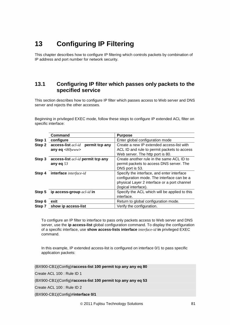
© 2011 Fujitsu Technology Solutions 81
13 Configuring IP Filtering This chapter describes how to configure IP filtering which controls packets by combination of IP address and port number for network security.
13.1 Configuring IP filter which passes only packets to the specified service
This section describes how to configure IP filter which passes access to Web server and DNS server and rejects the other accesses.
Beginning in privileged EXEC mode, follow these steps to configure IP extended ACL filter on specific interface:
Command Purpose Step 1 configure Enter global configuration mode Step 2 access-list acl-id permit tcp any
any eq <80|www> Create a new IP extended access-list with ACL ID and rule to permit packets to access Web server. The http port is 80.
Step 3 access-list acl-id permit tcp any any eq 53
Create another rule in the same ACL ID to permit packets to access DNS server. The DNS port is 53.
Step 4 interface interface-id Specify the interface, and enter interface configuration mode. The interface can be a physical Layer 2 interface or a port channel (logical interface).
Step 5 ip access-group acl-id in Specify the ACL which will be applied to this interface.
Step 6 exit Return to global configuration mode. Step 7 show ip access-list Verify the configuration.
To configure an IP filter to interface to pass only packets access to Web server and DNS server, use the ip access-list global configuration command. To display the configuration of a specific interface, use show access-lists interface interface-id in privileged EXEC command.
In this example, IP extended access-list is configured on interface 0/1 to pass specific application packets:
(BX900-CB1)(Config)#access-list 100 permit tcp any any eq 80
Create ACL 100 : Rule ID 1
(BX900-CB1)(Config)#access-list 100 permit tcp any any eq 53
Create ACL 100 : Rule ID 2
(BX900-CB1)(Config)#interface 0/1

© 2011 Fujitsu Technology Solutions 82
(BX900-CB1)(Interface BX900-CB1/0/1)#ip access-group 100 in
(BX900-CB1)(Interface BX900-CB1/0/1)#exit
(BX900-CB1)(Config)#exit
(BX900-CB1)#show access-lists interface 0/1 in
ACL Type ACL ID Sequence Number
-------- ------------------------------- ---------------
IP 100 1
(BX900-CB1)#

© 2011 Fujitsu Technology Solutions 83
14 Configuring SNMP Agent This chapter describes how to configure SNMP agent which informs MIB information of SNMP host.
14.1 Configuring SNMP Community
Beginning in privileged EXEC mode, follow these steps to configure SNMP v1/v2 agent community:
Command Purpose Step 1 configure Enter global configuration mode Step 2 snmp-server community
community-name1 Create a snmp community. The default access mode is READ-ONLY.
Step 3 snmp-server community community-name2
Create another snmp community.
Step 4 snmp-server community rw community-name2
Set the access mode of the SNMP community to READ-WRITE access mode..
Step 5 exit Return to global configuration mode. Step 6 show snmp Verify the configuration.
To configure snmp community, use the snmp-server global configuration command. To display the snmp configuration, use show snmp privileged EXEC command.
In this example, two snmp communities are created for read and read-write:
(BX900-CB1)(Config)#snmp-server community public
(BX900-CB1)(Config)#snmp-server community private
(BX900-CB1)(Config)#snmp-server community rw private
(BX900-CB1)(Config)#exit
(BX900-CB1)#show snmp
SNMP Community Name Client IP Address Client IP Mask Access Mode Status
------------------- ----------------- ----------------- ----------- --------
public 0.0.0.0 0.0.0.0 Read Only Enable
private 0.0.0.0 0.0.0.0 Read/Write Enable
(BX900-CB1)#

© 2011 Fujitsu Technology Solutions 84
14.2 Configuring SNMP User
Beginning in privileged EXEC mode, follow these steps to configure SNMPv3 agent user:
Command Purpose Step 1 configure Enter global configuration mode Step 2 snmp-server user v3-username
[auth <md5|noauth|sha> <0|7> v3-password [priv <des> <0|7> v3-encripted-password]]
Create a SNMPv3 username
Step 3 exit Return to global configuration mode. Step 4 show snmp user Verify the configuration.
To configure SNMPv3 user, use the snmp-server global configuration command. To display the SNMPv3 configuration, use show snmp user privileged EXEC command.
In this example, one SNMPv3 user is created for MD5 authentication and plain password:
(BX900-CB1)(Config)#snmp-server user v3_user auth md5 0 v3_password
(BX900-CB1)(Config)#exit
(BX900-CB1)#show snmp user
User Name Authentication Encryption
----------------- ------------------- -----------------
v3_user MD5 None
(BX900-CB1)#

© 2011 Fujitsu Technology Solutions 85
14.3 Configuring SNMP Remote EngineID
Beginning in privileged EXEC mode, follow these steps to configure SNMPv3 remote Engine ID:
Command Purpose Step 1 configure Enter global configuration mode Step 2 snmp-server engineID remote
<ipAddr|ipv6Addr> <engineid-string>
Create a remote engine ID
Step 3 exit Return to global configuration mode. Step 4 show snmp engineID Verify the configuration.
To configure SNMPv3 remote EngineID, use the snmp-server engineID global configuration command. To display the SNMPv3 configuration, use show snmp engineID privileged EXEC command.
In this example, one SNMPv3 remote EngineID is created for station 172.16.2.100:
(BX900-CB1)(Config)#snmp-server engineID remote 172.16.2.100 8000052301AC100266
(BX900-CB1)(Config)#exit
(BX900-CB1)#show snmp engineID
Remote EngineID IP Address
------------------------ ---------------
8000052301AC100266 172.16.2.100
(BX900-CB1)#
A remote engine ID is required when a SNMPv3 inform is configured. The remote engine ID is used to compute the security digest for authenticating and encrypting packets sent to a user on the remote host.

© 2011 Fujitsu Technology Solutions 86
14.4 Configuring SNMP Traps
Beginning in privileged EXEC mode, follow these steps to configure SNMP trap receiver:
Command Purpose Step 1 configure Enter global configuration mode Step 2 snmptrap trap-name ipaddress
snmpversion <snmpv1|snmpv2|snmpv3>
Create a SNMP trap and specify the client IP address to receive SNMP traps. trap-name should be SNMPv2 community string or SNMPv3 user name.
Step 3 exit Return to global configuration mode. Step 4 show snmptrap Verify the configuration.
To configure SNMP trap, use the snmptrap global configuration command. To display the SNMP trap configuration, use show snmptrap privileged EXEC command.
As configuring the SNMPv3 trap, the security level of the trap has to be the same or lower than the one of the SNMP user. (Refer to section 14.2 Configuring SNMP User)
In this example, create and activate the SNMPv2 and v3 trap for SNMP trap receiver:
(BX900-CB1)(Config)#snmptrap public 192.168.2.2 snmpversion snmpv2
(BX900-CB1)(Config)#snmptrap v3_user 192.168.2.2 snmpversion snmpv3 auth
(BX900-CB1)(Config)#exit
(BX900-CB)#show snmptrap
SNMP Trap Name IP Address SNMP Version Status
------------------- ----------------- -------------- --------
public 192.168.2.2 snmpv2 Enable
v3_user 192.168.2.2 snmpv3 Enable
(BX900-CB)#

© 2011 Fujitsu Technology Solutions 87
14.5 Configuring SNMP Informs
Beginning in privileged EXEC mode, follow these steps to configure SNMP informs receiver:
Command Purpose Step 1 configure Enter global configuration mode Step 2 snmpinform inform-name ipaddress
snmpversion <snmpv2|snmpv3> Create a SNMP inform and specify the client IP address to receive SNMP informs. Inform-name should be SNMPv2 community string or SNMPv3 user name.
Step 3 exit Return to global configuration mode. Step 4 show snmpinform Verify the configuration.
To configure SNMP informs, use the snmpinform global configuration command. To display the SNMP informs configuration, use show snmpinform privileged EXEC command.
As configuring the SNMPv3 informs, the security level of inform has to be the same or lower than the one of the SNMP user. (Refer to section 14.2 Configuring SNMP User)
In this example, create and activate the SNMPv2 and v3 informs for SNMP informs receiver:
(BX900-CB1)(Config)#snmpinform public 192.168.2.2 version snmpv2
(BX900-CB1)(Config)#snmpinform v3_user 192.168.2.2 version snmpv3 auth
(BX900-CB1)(Config)#exit
(BX900-CB)#show snmpinform
SNMP Inform Name IP Address SNMP Version Status
------------------- ----------------- -------------- --------
public 192.168.2.2 snmpv2 Enable
v3_user 192.168.2.2 snmpv3(Auth) Enable
(BX900-CB)#

© 2011 Fujitsu Technology Solutions 88
15 Configuring System Log This chapter describes how to configure system log function which sends system logs to syslog server.
Beginning in privileged EXEC mode, follow these steps to configure system logs to syslog server:
Command Purpose Step 1 configure Enter global configuration mode. Step 2 logging host hostaddress [port]
[severitylevel] Set the IP address and port number of logging host/server which syslog message to be sent.
Step 3 logging syslog To enable the syslog to configured hosts. Step 4 exit Return to privileged EXEC mode. Step 5 show logging Verify the configuration of syslog Step 6 show logging host Verify the configuration of syslog host
To create a syslog host, use logging host global configuration command. To enable or disable syslog, use logging syslog global configuration command.
In this example, create a logging host to sent critical messages and enable the syslog client.
(BX900-CB1)(Config)#logging host 172.16.2.109 514 critical
(BX900-CB1)(Config)#logging syslog
(BX900-CB1)(Config)#exit
(BX900-CB1)#show logging
Logging Client Local Port : 514
CLI Command Logging : disabled
Console Logging : disabled
Console Logging Severity Filter : alert
Buffered Logging : enabled
Syslog Logging : enabled
Log Messages Received : 94
Log Messages Dropped : 0
Log Messages Relayed : 14

© 2011 Fujitsu Technology Solutions 89
(BX900-CB1)#show logging hosts
Index IP Address Severity Port Status
----- ----------------- ----------- ------ -------------
1 172.16.2.109 critical 514 Active

© 2011 Fujitsu Technology Solutions 90
16 Configuring Pin Group
This chapter introduces the End-Host-Mode (EHM) and how to configure Pin Group in EHM.
16.1 End-Host-Mode Overview
End-Host-Mode (EHM) forwarding is based on server-to-uplink pinning. A given server interface (downlink port) uses a given uplink regardless of the destination it’s trying to reach. Therefore, connection blade will not learn MAC addresses from external LAN switches; they only learn MACs from servers inside the chassis. Therefore, the address table only contains MAC addresses of server blades connected to downlink ports. Addresses are not learned on frames from uplink ports; and frames from downlinks are allowed to be forwarded only when their addresses have been learned into the connection blade’s forwarding table. Frames sourced from servers inside the chassis take optimal paths to all destinations (unicast or multicast) inside. If these frames need to leave connection blade, they only exit on their pinned interface. Frames received on uplink ports are filtered, based on various checks, with an overriding requirement that any frame received from external LAN switches must not be forwarded back to the external LAN switches. However, connection blade does perform local switching for server to server traffic.
Connection blade FW provides an option to switch between the normal LAN switch and End-Host-Mode. However, a reboot of connection blade is required after the mode is changed. After customer changed the mode, the system will be rebooted automatically.
End-Host-Mode and Switch-Mode use the same startup configuration file. The spanning tree configuration will be hidden while the FW is running with End-Host-Mode. Customers will have their original spanning tree configuration after the FW is switched back to Switch-Mode. Other functions such as VLAN configuration are shared in Switch-Mode and End-Host-Mode.
In EHM, a “Pin Group” is introduced to define a pinning Group. The goal for Pin Groups is to provide partitioned bandwidth for the downlinks you configured. The Pin Group could guarantee the uplink bandwidth will not be shared with other downlink ports outside the Pin Group. User could configure the uplinks and downlinks to form a Pin Group so that the downlinks of the Pin Group will select the pinned interface from the uplinks of that Pin Group.
With EHM it is assumed that all uplinks connect to the same L2 network. Per default, all servers are pinned to dedicated uplink-ports. Thus no port-channel is required between CB and ToR (Top-of-Rack) switch. As an option, a standard port-channel can be configured on the uplink-site.

© 2011 Fujitsu Technology Solutions 91
16.2 Creating Pin Group
Beginning in privileged EXEC mode, follow these steps to configure Pin Group:
Command Purpose Step 1 configure Enter global configuration mode. Step 2 pin-group pinGroupName Create a pin group. Step 3 exit Return to privileged EXEC mode. Step 4 show pin-group
[<pinGroupName>] Verify the configuration of pin group
To create a Pin Group, use pin-group global configuration command. To delete a Pin Group, use no pin-group global configuration command.
In this example, create a Pin Group called “QoS”.
(BX900-CB1)(Config)#pin-group QoS
(BX900-CB1)(Config)#exit
(BX900-CB1)#show pin-group QoS
Auto VLAN Uplink Synchronization............... Disable
Repinning Timer................................ 10
Name Uplink Ports Downlink Ports
-------------------- -------------------- --------------------
QoS
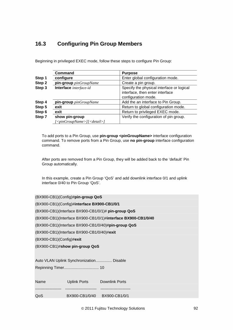
© 2011 Fujitsu Technology Solutions 92
16.3 Configuring Pin Group Members
Beginning in privileged EXEC mode, follow these steps to configure Pin Group:
Command Purpose Step 1 configure Enter global configuration mode. Step 2 pin-group pinGroupName Create a pin group. Step 3 Interface interface-id Specify the physical interface or logical
interface, then enter interface configuration mode.
Step 4 pin-group pinGroupName Add the an interface to Pin Group. Step 5 exit Return to global configuration mode. Step 6 exit Return to privileged EXEC mode. Step 7 show pin-group
[<pinGroupName>][<detail>] Verify the configuration of pin group.
To add ports to a Pin Group, use pin-group <pinGroupName> interface configuration command. To remove ports from a Pin Group, use no pin-group interface configuration command.
After ports are removed from a Pin Group, they will be added back to the ‘default’ Pin Group automatically.
In this example, create a Pin Group ‘QoS’ and add downlink interface 0/1 and uplink interface 0/40 to Pin Group ‘QoS’.
(BX900-CB1)(Config)#pin-group QoS
(BX900-CB1)(Config)#interface BX900-CB1/0/1
(BX900-CB1)(Interface BX900-CB1/0/1)# pin-group QoS
(BX900-CB1)(Interface BX900-CB1/0/1)#interface BX900-CB1/0/40
(BX900-CB1)(Interface BX900-CB1/0/40)#pin-group QoS
(BX900-CB1)(Interface BX900-CB1/0/40)#exit
(BX900-CB1)(Config)#exit
(BX900-CB1)#show pin-group QoS
Auto VLAN Uplink Synchronization............... Disable
Repinning Timer................................ 10
Name Uplink Ports Downlink Ports
-------------------- ------------------------ -----------------------
QoS BX900-CB1/0/40 BX900-CB1/0/1

© 2011 Fujitsu Technology Solutions 93
(BX900-CB1)#show pin-group QoS detail
Auto VLAN Uplink Synchronization............... Disable
Pin Group Name................................. QoS
Downlink Ports Selected Interface Pin Stats
-------------------- -------------------------- ----------
BX900-CB1/0/1 Idle
(BX900-CB1)#

© 2011 Fujitsu Technology Solutions 94
16.4 Configuring Auto VLAN Uplink Synchronization
Beginning in privileged EXEC mode, follow these steps to configure Auto VLAN Uplink Synchronization feature:
Command Purpose Step 1 configure Enter global configuration mode. Step 2 pin-group uplink-sync {auto |
manual} Enable uplink sync feature. Auto for continuous uplink VLAN synchronization and manual for one-time uplink VLAN synchronization.
Step 3 exit Return to privileged EXEC mode. Step 4 show pin-group Verify the configuration of Auto VLAN
Uplink Synchronization feature.
To enable Auto VLAN Uplink Synchronization feature, use pin-group uplink-sync auto global configuration command. To disable Auto VLAN Uplink Synchronization feature, use no pin-group uplink-sync global configuration command.
(BX900-CB1)(Config)#pin-group uplink-sync auto
(BX900-CB1)(Config)#exit
(BX900-CB1)#show pin-group
Auto VLAN Uplink Synchronization............... Enable
Repinning Timer................................ 10
Name Uplink Ports Downlink Ports
-------------------- -------------------------- --------------------
default BX900-CB1/0/37, BX900-CB1/0/2, BX900-CB1/0/3,
BX900-CB1/0/38, BX900-CB1/0/4, BX900-CB1/0/5,
BX900-CB1/0/39, BX900-CB1/0/6, BX900-CB1/0/7,
BX900-CB1/0/41, BX900-CB1/0/8, BX900-CB1/0/9,
BX900-CB1/0/42, BX900-CB1/0/10, BX900-CB1/0/11,
BX900-CB1/0/43, BX900-CB1/0/12, BX900-CB1/0/13,
BX900-CB1/0/44, BX900-CB1/0/14, BX900-CB1/0/15,
BX900-CB1/0/45, BX900-CB1/0/16, BX900-CB1/0/17,
BX900-CB1/0/46 BX900-CB1/0/18, BX900-CB1/0/19,
BX900-CB1/0/20, BX900-CB1/0/21,
BX900-CB1/0/22, BX900-CB1/0/23,

© 2011 Fujitsu Technology Solutions 95
BX900-CB1/0/24, BX900-CB1/0/25,
BX900-CB1/0/26, BX900-CB1/0/27,
BX900-CB1/0/28, BX900-CB1/0/29,
BX900-CB1/0/30, BX900-CB1/0/31,
BX900-CB1/0/32, BX900-CB1/0/33,
BX900-CB1/0/34, BX900-CB1/0/35,
BX900-CB1/0/36
QoS BX900-CB1/0/40 BX900-CB1/0/1
(BX900-CB1)#

© 2011 Fujitsu Technology Solutions 96
16.5 Configuring Pinning State
Beginning in privileged EXEC mode, follow these steps to configure pinning state for a downlink:
Command Purpose Step 1 configure Enter global configuration mode. Step 2 Interface interface-id Specify the physical interface or logical
interface, then enter interface configuration mode.
Step 3 no pinning Disable the pinning state for the interface. Step 4 exit Return to global configuration mode. Step 5 exit Return to privileged EXEC mode. Step 6 show pin-interface interface-id Verify the pinning state of the interface
To configure an interface to participate the pinning state, use pinning interface configuration command. To configure an interface not to participate the pinning state, use no pinning interface configuration command.
(BX900-CB1)(Config)#interface BX900-CB1/0/1
(BX900-CB1)(Config)#no pinning
(BX900-CB1)#show pin-interface BX900-CB1/0/1
(BX900-CB1)#show pin-interface BX900-CB1/0/1
Interface...................................... BX900-CB1/0/1
Pin Group Name.................................
Selected Pin-Interface.........................
Pin State...................................... Disable
(BX900-CB1)#