principle of massive support in the opposed anvil high pressure apparatus
TRANSCRIPT

PramS.ha, Vol. 18, No. 1, January 1982, pp. 1-15. © Primed in India.
Principle of massive support in the opposed anvil high pressure apparatus
M O H A M M A D YOUSUF and K GOVINDA RAJAN Reactor Research Centre, Kalpakkam 603 102, India
MS received 24 April 1981 ; revised 13 November 1981
Abstract. The Bridgman anvil technique offers a simple and versatile means of generating very high pressures required in solid state studies. The opposed anvil technique is based on the principle of massive support. The practical case of a gas- ketted anvil is considered, and an expression for the maximum pressure generated under massive support is derived in terms of the geometric parameters, the strength of the anvil material and the gasket properties. In particular, for a given maximum pressure, it is possible to calculate the taper angle, the taper height and the gasket thickness from this expression. The anvil is assumed to be in the elastic region under load. Good agreement is obtained between the calculated and the experimental values for the massive support factor (MSF) for various taper angles. By choosing the proper geometry, it is possible to achieve a pressure as high as 130 kbar in an alloy steel anvil. It has been dearly found that the straight portion, where the taper ends, does not really take any part in changing the stress pattern. Thus the minimum straight portion can serve the purpose, and will result in material saving. Anvils exhibit yielding at very high pressure. It is also pointed out that a further strengthen- ing of the anvil can extend the ultimate pressure. Several methods of further strengthening the anvils are discussed.
Keywords. Very high pressures; Bridgman anvil; massive support; alloy steel anvil; yielding; further strengthening.
1. Introduction
The Bridgman opposed anvil technique is very widely used in high pressure solid state studies (Bandyopadhyay et al 1980; Mao and Bell 1979; Bassett 1979; Dricka- mer 1970; Wakatsuki et al 1972; Vereschagin et al 1969; Govinda Rajan et al 1981 and the references quoted therein). This is because the method is simple, easy to assemble and inexpensive. This works on the principle of massive support, a labora- tory analogue of the tapered foundation design, employed by civil engineers, since antiquity, to support the great loads of huge structures by the comparatively softer earth (Merritt 1968). That the taper reduces the large working stresses quickly to tolerable levels has been realised for a long time, and yet no quantitative under- standing of the massive support was seriously pursued. In this paper, the design considerations of the anvil that have been developed in order to arrive at an expression for the massive support factor are presented.
In § 2 an expression for the massive support factor (MSV) within the realm of prin- ciple stress theory is derived and the MSF is found to be proportional to the square of the ratio of the overall diameter to the working face diameter.
In § 3, the experimental studies ar~described. The compression test on anvils with

2 Mohammad Yousuf and K Govinda Rajan
varying straight portions indicate that the load necessary to cause yielding is inde- pendent of the length of the straight portion. The massive support factor is obtained for various taper angles, and very good agreement between the experimental results and the calculated values is obtained upto MSF N 14. At higher pressures severe yielding or cupping takes place and hence the expression for MSF needs to be corres- pondingly modified in order to accommodate the elasto-plastic behaviour of the anvil. By performing the electrical resistivity measurements with alloy steel anvils, it is possible to observe the structural phase transition in Pb occurring at 130 kbar.
In § 4, the experimental results are discussed. Then the limitations of the calculations carried out in § 2 are pointed out, and the possible methods for further strengthening the anvil in an appropriate manner are indicated.
In § 5, conclusions are drawn from the experimental findings. And it is pointed out that a general MSF calculation needs to be developed which will be valid both in the elastic and elasto-plastic regions.
2. Theory of massive support
The anvil geometry is shown in figure I. The material properties entering the calculations are: S A, the compressive strength of the anvil, and/~ the coetficient of friction between the anvil and the gasket. The geometrical parameters are: 2a, the anvil face diameter (the working diameter), Z, the depth into the tapered portion, Zb, the depth at which the tapered portion ends, a, the taper angle, and h, the critical thickness of the gasket. The problem is to obtain a design formula for the maximum pressure that can be generated at the centre of the anvil face (Z = 0, r = 0), in terms of the anvil parameters listed above. Denoting P(Z, r) as the stress across any Z plane, the stress distribution P (0, r) on the top of the anvil face when a thick gasket is employed is given by (Jackson and Waxman 1963; Mohammad Yousuf and Govinda Rajan 1979),
P(O, r)---- A exp [ ~ ( a - - r)], (1)
GASKE~
G Figure 1. The anvil geometry, showing the anvils and the gasket before loading. The various geometrical parameters are defined in the sketch.

MSF in the opposed anvil high pressure apparatus 3
where r is measured within any Z-plane, and A is related to the strength of the gasket. It must be pointed out that (1) is a limiting equation and is not valid for all pressures. For example, the stress distribution is much more complicated near the yield point. The load to be applied to generate a given stress profile P(0, r) is given by
a
L = 2 ~ r r d r A e x p ( a - - r ) =
0
where B = 2lz/h.
Assuming that across any other Z-plane, the stress is given by
P(Z, r) ----- A' exp [B' (a + Z cot ~ -- r)], (3)
the total load applied at any plane (Z, r) is given by,
a+Z cot a f 2zrr dr A' exp [B' (a + Z cot ~ -- r)], L' 0
= 2zrA__._j' [exp {B' (a + Z cot a)) -- B' (a + Z cot a) -- 1]. B'~
(4)
Since there is no loss in load, L = L ' ; and thus from (3) and (4) one gets by comparing:
B ' = B a (5) a + Z cot
and, A ' = A [ a + zacot a]3" (6)
On substituting the values of A' and B' in (3), the stress distribution is given by
P(Z , r )= A(a + zacot a f e x p [ B a ( a + Z c o t a - - r)/(a W Z cot a)].
Let the tapered portion end at Z = Zb (say) and the straight portion begin there- after. The stress distribution of the form (7) averages out rapidly. That is
P (Z = Zb, r = O) = Pay (Zb). (8)
Since after Z =Zb, there is no tapered portion, there is no contribution to the mass- ive support factor from the straight portion. This aspect is further discussed in § 4. From (7), Pay (Z~) is obtained to be
Pay a f = e x p (Ba) , a + Z~ cot
(9)

4 Mohammad Yousuf and K Govinda Rajan
and the load applied to generate stress Pav (Zb) is
L = Pay (Zb)" *r" (a + Zb cot a) 2. (10)
On comparing (2) and (10),
Pay (Zb) = 2 A exp (Ba) -- Ba -- 1 B 2 ( a + Z b c o t a ) ~ ' (11)
and from (1)
P [0, r = 0] = P (0, 0) = a exp (Ba),
so that, A = P(0, 0) exp (--Ba). (12)
On substituting this value of A in (11), one gets
P(0, 0) = {B z exp (Ba) (a + Z~ cot e)2 Pav (Zb). (13) exp (Ba) -- Ba -- 1
It is now postulated that when Pay (Zb) approaches S A, the compressive strength of
the anvil, the anvil fails. Hence, the expression for the maximum pressure possible to generate at the centre of the anvil before failure is given by
P(0, 0) = Pmax = ½ B~ exp (Ba) (a + Z~ cot a) ~ S A. (14) exp (Ba) -- Ba -- 1
Similarly it is also postulated that as soon as Pay (Z~) --> (ay) A, the compressive yield strength of the anvil, the anvil yields. Therefore, the maximum pressure that can be generated at the centre of the anvil before it yields is given by replacing Pay (Z~) in (15) by (ay)A, that is
P (0, 0) -'=- Pmax = ½ B2 exp (Ba) (a + Zb cot ~)z (*Y)A" (15) exp (Ba)'-- Ba -- 1
The massive support factor (MSF) is defined as the ratio of the maximum pressure generated at the centre of the anvil to the compressive strength of the anvil, S A; that is,
MSF -- Pmax_ ½ B ~ exp (Ba) (a + Zb cot a) ~. (16) S A exp ( B a ) - B a - 1
It may be noted that when B = 21~/h ~ O, that is, when the gasket amplitieation is unity,
B e 2 ~ ' t ~ - -
B=0exp ( B a ) - B a - 1 a S'

MSF in the opposed anvil high pressure apparatus 5
and, ha this limit,
M S F = ( a + Z o c ° t a f " a (17)
On substituting b = a + Zo cot a,
Pmax = SA b'/a2" (18)
The MSF for the thin gasket case thus turns out to be ba/a 2. The general expression for maximum pressure generated at the centre of the thick gasket is therefore
P (0, 0) = s a (b/a)' ( o A), (19)
where (G A) = ½ a s B ~ exp (Ba) [exp (Ba) -- Ba -- 1]-1, which is the interaction term between the anvil and the gasket. This term is the well-known gasket ampli- fication factor and approaches unity for a very thin ~ gasket. Thus for a uniform stress distribution (thin gasket case) on the top of the anvil face, maximum pressure generated at the centre is just the product of the compressive strength of the anvil and the ratio of the squares of the overall and working face diameters (equation 18).
3. Experimental studies
Experiments were performed with EN24 anvils and three kinds of studies, namely, the compressive displacement test, the yield test and the electrical resistivity measurements were made.
3.1 Compressive displacement test
Anvils fabricated out of EN24 (gsl 4340) alloy steel were used after hardening to Re 58. In order to retain the maximum brittleness tempering was not performed. Anvils with various b/a ratios, taper angles and untapered lengths were loaded and the load vs. compressive displacement characteristics with thick gaskets were obtained. The load from a 100 tonne universal testing machine was increasingly applied on the anvil, till the automatic indicator in the press showed that either the anvil had failed or had yielded. Some of the compression test results are reproduced in figure 2. Here the compressive displacements are indicated and the loads at which the anvil- yielding started or the anvil had a failure, are also indicated with arrows. It is noticed that as soon as the anvil starts yielding, the compressive displacement starts deviating from linearity, indicating that the maximum pressure generated at the centre of the anvil may no longer be represented by (19). That is, (19) needs appropriate correc- tions in order to estimate the pressure in the centre of the anvil. The failure of the anvils was observed preferentially in the Z-plane. Moreover in most of the failed anvils, the front portion remained almost intact, while the straight rear portion always fractured into two parts. That is, the failure always starts from the rear portion and proceeds to the working face. These failure patterns support the proposition made in

6 Mohammad Yousuf and K Govinda Rajan
I - - 7
:~m ~72-s) 1
. . . I i1.
E
@ l,s ° • J
- o
YIELDING LOAD i ANGLI: IN TONNE5
t
LOAD (tonne) Figure 2. The load test in compression on anvils. The results indicate that while the yielding load increases with decreasing taper angle, it is independent of the length of the straight portion for a given load.
§ 2 that as soon as Pay (Zb) reaches SA in the straight portion, the anvil fails. Photo-
graphs of the failed anvils are shown in figure 3. It is noticed from figure 2 that the yielding or the failure of the anvil is independent
of the lengthof the straight portion and that the failure load is a strong function of the taper angle. It is seen that for very small taper angles, the MSF exhibits saturation. These results are shown in figure 4. The comparison of the experimental values with the calculated values indicates that the agreement is very good in almost the full range of the taper angles except at small taper angles.
3.2 Yield test
Experiments on the anvils with and without the straight portions were performed. It was observed that the yielding in the anvil takes place at almost the same load for both the types of anvil, supporting the proposition that as soon as the straight por- tion is reached, the stress distribution averages out and this average stress propagates in the straight portion. Several experiments were performed to study the yielding behaviour of the alloy steel anvils. For thick gasketted anvil, the equidepression

WO
RK
ING
FA
CE
-:
:
t~
Fig
ure
3.
Fai
lure
p
atte
rn
obse
rved
in
anvi
ls.
The
se
wer
e de
libe
rate
ly
load
ed
to f
ailu
re a
nd
the
p
ho
tog
rap
h c
lear
ly s
how
s th
at
frac
ture
alw
ays
star
t fr
om
the
rea
r fa
ce a
nd p
rogr
esse
s to
war
ds t
he w
orki
ng f
ace.
-4


MSF in the opposed anvil high pressure apparatus 9
MSL 7S 030
20 II a: 18 t • EXPERIMENTAL RESULTS o • ~ ON QUENCHED EN-2t. -
I6 ~ ANVILS I / , - ~
* ~ "--CALCLILA TED 12-
Z
~ 8 - - - -
I ! I I I I I 0 10 20 30 L.O 50 60 70
TAPER ANGLE Figure 4. Massive support factor obtained for different taper angles on EN-24 anvils. The solid line is obtained from (19).
E__qui- de.pression
-2:t
-~o Ca) -tO2
5
AFTER LOADING BEFORE LOADING
2 ~
Equi-depression contour
GASKET
~ 1 ......... ANd/ILl ...........
BEFORE LOADING
~ 1 l I T I i I } I I I l l ~ [ I I I I I t I F ~
AFTER LOADING
Figure 5. Yielding behaviour of steel anvils. The depression was measured by a sensitive dial gauge. Anvil loaded with (a) a thick gasket, and (b) a thin gasket.
contours were obtained. The results are shown in figure 5a, where the depressions at the step of 1 mm in a 12 mm working fac~ diameter anvil are shown. These depres- sions can be taken to represent the existing pressures at those places when the anvil was under load. The stress distribution exhibited by the plot is exponential in nature lending direct support to the form of the stress distribution assumed in (1). Further, the equidepression profile can be used to obtain/~, the coefficient of friction between the gasket and the anvil, when a thick gasket has been employed. From the data /~ ~ 0-2 is obtained for the combination of pyrophyllite gasket and EN24 anvils.

10 Mohammad Yousuf and K Govinda Rajah
Experiments were also performed with very thin gaskets and the results are shown in figure 5b. It is observed that the yielding profile is somewhat squarewell like, indi- cating that the stress distribution throughout the top of the anvil face is uniform; that is, no gasket amplification (GA) takes place in such a case. This proves the result obtained in (18), that for a very thin gasketted anvil, the maximum pressure that can be generated is
P(O, O) = S A (b=/a~).
3.3 Electrical resistivity measurements
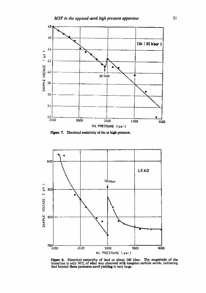
Four probe electrical resistivity measurements were done with heat treated (Rc 58) alloy steel anvils, and the sample assembly and electrical lead configuration were arranged as described elsewhere by Govinda Rajan et al (1981). Bismuth, tellurium, thallium, tin and lead were loaded and the well-known resistance jumps in these occurring respectively at (24, 74), 39, 40, 95 and 130 kbar were observed; The results for Bi, Sn and Pb are shown in figures 6-8.
4. Discussion
The results on MSF vs. taper angle indicate that the agreement between the experi- mental results and the calculated values is very good. The saturation of MSF at small taper angles can be explained if the present calculation is extended to the elastoplastic
60
I
25.4kbar
I BISMUTH
>
~- 20 - < (/3
I 7Z, k b a r
O 0 1000 2000
OIL PRESSURE (ps i ) Figure 6. Electrical resistivity of bismuth at high pressure studied with alloy steel anvils.
MSF in the opposed anvil high pressure apparatus
/.8,
/.4 ..¢
42 LLI L.~
~0 0
I.gl ~_ 3B ~E < U'I 36
3~
32
95 kbi~r ~
2500
Figure 7.
3000 3500 4000
OIL PRESSURE ( p s i )
Electrical resistivity of tin at high pressure.
TIN ( 9S kb~- )
/,500
11
UIJ
0
< U')
840
130 kbar
LEAD
82O
B00 ~ , ~ ° ~ o o ~ ,
780 1 4000 4500 5000 5500 6000
OIL PRESSURE ( psi ) Figure 8. Electrical resistivity of lead to about 140 kbar. The magnitude of the transition is only 30~o of what was observed with tungsten carbide anvils, indicating that beyond these pressures anvil yielding is very large.

12 Mohammad Yousuf and K Govinda Rajan
regime because yielding is more for small taper angles. It is noticed that the MSF VS. taper angle characteristic is unchanged with anvils of different straight portions. Thus it is only from practical considerations like aligning, mounting the sample assembly etc. that one retains some straight portion in the anvil.
It is observed from the resistivity experiments that it is possible to use alloy steel anvils, with appropriate taper angle and taper depth, to a pressure of upto 130 kbar. However, the magnitudes of the resistivity jumps are observed to be less than those reported in the literature (Dunn and Bundy 1978; Bundy 1968). While the earlier workers used tungsten carbide anvils, alloy steel anvils have been used in the present work, and it is possible to interpret the results by taking into account the yielding of the anvil face under high stress. While (16) and (17) give an expression for the MSF and the maximum stress that can be generated, there is a limitation, in practice, set by the yielding of the anvil face. The yielding of the anvil is still not fully under- stood. However, one can borrow the results from the Hertz contact stress problem, and estimate the magnitude of the shear stress z and the depth Zma x from the working
face at which it reaches a maximum (Ruoff 1977). The relevant expressions are:
"rmax -- 2 (I _}_fz)u2 2 (1 +~)a/z ' (20)
where s - max _ 0 + 2a \ "7-----2v 1 , and v is the Poisson's ratio.
The yielding in the anvil can be explained in the following way. After a certain limiting pressure has been reached, further increase in the load is not fully transferred into increasing the sample pressure. Rather a significant part of it is absorbed by the anvil in forming a cup or a lens. According to this approach, when ~'rnax, the maximum shear stress reaches a certain limiting value at Z-----Zma x, the anvil portion at this point exhibits the onset of yielding. And this portion of the anvil due to yielding would not be able to support the anvil portion at Z ---- 0 (the region of highest pressure) as rigidly as it would have before the onset of yielding. Consequently, the portion at Z = 0 to Z=Zma x and r~<a acquires the shape of a lens or a cup (because of the exponential nature of the stress distribution), and further increase in the load- ing cotitributes more to the increase in the lens curvature than to the sample pressure. For a thick gasket, a cup-shaped profile results, while for a very thin gasket, a square well results. Figure 5 displays these observed behaviours. It is possible to circumvent yielding to some extent and raise the working pressure range of the alloy steel anvil by designing special anvils.
4.1 Anvil with a cavity filled with fluid
A successful way of avoiding the yielding is by having a cavity inside the anvil and filling it with a liquid of high freezing pressure. Thus the maximum shear stress is allowed to take place inside the liquid, which cannot sustain any shear stress and in effect the region Z < Zma x has a compressive hydrostatic backup equal in mag-
nitude to the average shear stress. The anvils so designed as shown in figure 9a

MSF in the opposed anvil high pressure apparatus 13
~ ~Ft.Y A N V I L ~
~ \ \ \ \ \ \ \ \ \ \ \ \ \ \ ~ I (a)
I i (b)
Figure 9. Some methods of anvil strengthening. (a) Anvil with a cavity in its under- belly which is filled with a fluid, (b) Anvil fitted with an insert of a hard metal, (e) Anvil prestressed by shrunk-fitted cylinder. Processes (b) and (c) pose fabrication problems.
work very well (Mohammad Yousuf and Govinda Rajan 1980) and pressures upto 140 kbar can be obtained with them. 4 • 1 ethanol : methanol liquid mixture was used to fill the cavity. The seal between the anvil and the base plate is an O-ring or a teflon gasket. The anvil is inverted, the fluid is filled and the base plate is lightly pressed to accomplish the seal.
4.2 Anvil fitted with a rod o f hard material
A second way to strengthen the anvil is to shrink-fit a hard metal in the anvil in the way shown in figure 9b. In this design the anvil has a built-in compression. Thus Pao (Zb) is correspondingly increased by the compressive stress.
4.3 Anvil fitted with a cylinder
The third possible way to strengthen the anvil will be to support the tapered portion (Bundy 1977; Balchan and Drickamer 1961). Thus, in effect, the tapered portion is under compression. Hence, the applied load has to circumvent this barrier before pulling the tapered region under tension. Thus the pressure capability of the anvil is accordingly raised. This added flank support can either be imparted during the main loading via the tapered gaskets, or be built in by shrink-fitting a cylinder as shown in figure 9c. This way Pay (Zb) is raised by the amount of shrinkage stress along
Z-direction.
4.4 Anvils fitted with binding rings
It is common in the literature (Christiansen et al 1961) to find binding rings fitted to the anvils, with the analogy drawn from multilayer pressure vessel design (Faupel 1964). While the shrink-fitted binding rings in a pressure vessel increasethe pressure retaining capacity by the built-in compressive stress due to interference fitting, the similar kind of interference fitted binding rings in an anvil do not serve any useful purpose (Lees 1966).

14 M o h a m m a d Yousu f and K Govinda Rajan
5. Conclusion
(a) An expression for the maximum pressure possible to generate in an opposed anvil apparatus is developed. The expression is valid in the elastic regime. Experi- ments with EN24 anvils have been done and it is observed that a very good agreement between the experimental results and the calculated values of ~,tsF exists in the elastic region.
(b) It is possible to generate a pressure as high as 130 kbar with alloy steel anvils, (which have a nominal strength ,-~ 10 kbar) with appropriate choice of the taper angle and taper depth for a given working face diameter.
(c) It is observed that the straight portion in the anvil does not take any part in reducing the stress distribution. Once the straight portion (Z ~ Zb) is approached, the stress distribution averages out, and the same average value propagates along the Z-direction without any attenuation. Therefore, it is possible to save material by minimizing the straight portion after the taper depth.
(d) The shape and the magnitude of the resistivity jumps indicate that they are somewhat different from those obtained with tungsten carbide anvils, especially at very high pressures. These can be explained by taking into account the plastic behaviour (yielding) of the anvil.,
(e) Finally a few methods for the further strengthening of the anvils to circumvent yielding are described.
Acknowledgements
The authors thank Dr G Venkataraman for his keen interest and encouragement in this work. They are happy to acknowledge a stimulating discussion they had with Prof. E S Raja Gopal on some aspects of this work. It is a pleasure to thank M/s V Anandkumar, N Kannan, S Aravamuthan, A S Raghu and S V Nagabhushana for their help and cooperation during the various stages of this work. They also thank Miss V Hemalatha for skillful typing and the referee for useful suggestions.
References
Balchan A S and Drickamer H G 1961 Rev. $ci. Inst. 32 308 Bandyopadhyay A K, Nalini A V, Gopal E S R and Subramanyam S V 1980 Rev. Sci. Inst. 51 136 Bassett W A 1979 Ann. Rev. Earth Planet. Sci. 7 357 Bundy F P 1968 in Accounts eharacterisation o f the high pressure environment (Washington: National
Bureau of Standards) Bundy F P 1977 Rev. Sei. Inst. 48 591 Christiansen E B, Kistler S S and Gogarty W B 1961 Rev. $ci. Inst. 32 775 Drickamer H G 1970 Rev. Sci. Inst. 41 1667 Dunn K J and Bundy F P 1978 Rev. Sei. Inst. 49 365 Faupel J H 1964 Engineering design: A synthesis o f stress analysis and material engineering (New
York: John Wiley) Govinda Rajan K, Sankara Sastry V and Rita Khanna 1981 Rev. Sei. Inst. (To be published in the
Nov. issue) and the references therein Jackson J W and Waxman M 1963 High pressure measurement (eds) A A Giardini and E C Lloyd
('New York: Butterworths) p. 39

M S F in the opposed anvil high pressure apparatus 15
Lees J 1966 in Advances in high pressure research (ed) R S Bradley (London and New York: Academic Press) Vol. I p. 1
Mao H K, Bell P M, Shaner J and Steinberg 1979 in High pressure science and technology (ed) K D Timmerhaus and M S Barber (New York: Plenum) Vol. 1 p. 1
Merritt F S 1968 Standard handbook for civil engineers (New York: McGraw-Hill) p. 7-22 Mohammad Yousuf and Govinda Rajah K 1979 Nucl Phys. Solid State Phys. (India) C22 815 Mohammad Yousuf and Govinda Rajan K 1980 Nucl. Phys. and Solid State Phys. (India) C23 (In
Press) Ruoff A L 1977 High pressure science and technology (eds) K D Timmerhaus and M S Barber (New
York: Plenum Press) Vol. 2 p. 525 Verschagin L F, Semerehan A A, Kusin and Popova S V 1969 Soy. Phys. Dokl. 6 41 Wakatsuki M, Ichinose K and Aoki T 1972 Jpn. J. Appi. Phys. U 578