principles and hardw are of electrolytic...
TRANSCRIPT
Mettler-Toledo Ingold, Inc.
Address 36 Middlesex Turnpike Bedford, MA 01730Phone 781-301-8800Customer Service 800-352-8763Fax 781-301-8920Internet http://www.mtpro.com
PRINCIPLES AND HARDW ARE OF ELECTROLYTIC
CONDUCTIVITY M EASUREM ENTS
Kenneth M. Queeney
Product Manager
METTLER TOLEDO Ingold
299 W ashington Street
W oburn, MA 01801
KEYW ORDS
Conductivity, Electrolytic conductivity, Resistivity, Theory, Design, Applications
ABSTRACT
Electrolytic conductivity is a widely used analytical parameter in the Industrial Processing market
segment. It is used throughout the "W ater Cycle" ranging from water preparation, to chemical
processes, to wastewater treatment. Applications include water purity analysis following ion-exchange
and/or reverse osmosis units, monitoring washing and rinsing stages, chemical concentration control of
dilution processes, monitoring chemical reactions, and measurement of ionic content in industrial
wastewater.
Given the diversity of the applications, it should not be surprising that there is not a single measurement
technology which is optimized for every situation. Rather, there are three main methodologies for
electrolytic conductivity: two-electrode, four-electrode, and inductive. The classical two-electrode
sensors are well positioned for measurement in high purity water and relatively low conductivity ranges.
The four-electrode sensors are suited to mid to high ranges and are more resistant to fouling than two-
electrode designs. The inductive sensors cover mid to very high conductivity ranges, and are
particularly resistant to fouling.
This paper examines the principles of each measurement technique, the advantages and disadvantages of
each, and describes specific industrial situations where each sensor type is best applied.
Copyright by ISA – The Instrumentation, Systems, and Automation Society
Presented at the ISA 48th Analysis Division Symposium, April 27 – May 1, 2003
Calgary, Alberta, Canada

INTRODUCTION
Electrolytic conductivity is one of the oldest analytical methodologies having a 200+ year history.
Investigating the electric shock capabilities of the torpedo fish, Henry Cavendish is credited with
performing some amazingly accurate conductivity experiments dating back to 1776 [1].
Some of the reasons that this method has endured are the simplicity of the basic measurement, its low-
cost, robust sensors, and the high accuracy of the technique. Further, the technology has evolved
substantially since the initial findings of Cavendish to allow use in areas previous not possible. This
paper will focus on on-line industrial measurement of aqueous solutions.
THEORY OF ELECTROLYTIC CONDUCTIVITY
TERMINOLOGY
Electrolytic conductance can be defined as the ability of a solution to carry an electric current. The
conductance, L (with units of Siemens (S)), is defined as the reciprocal of the cells resistance, R (ohms)
[2].
L = 1/R (1)
Further, the "specific conductance" or conductivity, (units S/cm) is expressed relative to standard
conditions of a fixed geometry of the electrode cell configuration. The reference conditions are for a
cell with electrodes with a surface area (A) of 1 cm2 each spaced a distance (d) 1 cm apart such that
= (1/R)(d/A) (2)
Therefore, the conductivity of a solution can be determined by measuring the resistance of a cell with
defined electrode geometry.
BASIC PRINCIPLE
As illustrated in Figure 1A, the current is carried by ions dissolved in solution. Applying a potential
between the two electrodes will cause positive ions to migrate toward the negatively charged electrode
and negative ions to be drawn to the positive electrode. The potential applied is below activation
voltage so that no reaction takes place at the electrodes [3].

FIGURE 1A - CONDUCTIVITY CELL DESIGN FIGURE 1B - POLARIZATION
It may be apparent from the illustration that the more ions that are available, the greater the current
carrying capability. This is indeed the case in dilute solutions such that the total conductivity is the sum
of the conductivity of the individual ions. The ability of the bulk solution to conduct electricity is also
dependent upon the specific ions present. Each ion has a different mobility in solution, affecting its
capability of carrying current. Table 1 lists the equivalent ionic conductance, , of several common ions
[2]. It can be seen that the relative conductance varies substantially depending on the specific ion, with
hydrogen ion and hydroxide ion being far more conductive than all other ions.
Cation 0 Anions 0
H+
349.8 OH-
198.6
K+
73.5 Fe(CN)6-4
110.5
NH4+
73.5 SO4-2
80.0
Pb+2
69.6 Br-
78.1
La+3
69.6 I-
76.8
Ba+2
63.6 Cl-
76.4
Ag+
61.9 NO3-
71.4
Ca+2
59.5 CO3-2
69.3
Mg+2
53.1 ClO4-
67.3
Na+
50.1 HCO3-
44.5
Li+
38.7 CH3O2-
40.9
TABLE 1 – EQUIVALENT IONIC CONDUCTANCE OF VARIOUS IONS
Electrode
plate
1 cm
CondVAC
+
-
-
-
-
-
-
- +
++
+
+
++
1 cm
1 cmSolution
++
+
+
+
+
+
--
-
-
-
-
- +
Ion Clouds

In consideration of all the above conditions, the conductance, L, can be expressed as [4]:
L = (A/d )10-3
ziCi I (3)
Where: zi = ionic charge of ion "i"
Ci = molar concentration of ion "i"
One would expect conductance to vary linearly with concentration according to equation 3. While this
holds true approaching infinite dilution, for many common applications, empirical correlations must be
established. The conductivity response is not only non-linear at high concentrations, it can actually
reach a point where additional ions will decrease the overall concentration as illustrated in Figure 2.
Perhaps the most interesting example of this phenomenon is the conductivity vs. concentration curve for
sulfuric acid. As shown in Figure 2, this series of peaks and troughs resembles a roller coaster more
than a typical analytical calibration curve [5].
0
100
200
300
400
500
600
700
800
900
0 10 20 30 40 50 60 70 80 90 100
% by W eight
Mil
liS
iem
en
s/c
m
Sodium Chloride Potassium Chloride Sodium Hydroxide
Hydrochloric Nitric Acid Sulfuric Acid
FIGURE 2 – CONDUCTIVITY vs. CONCENTRATION CURVES
POLARIZATION
If a DC voltage is applied, ions would build up an "ion cloud" near the surface of the electrode as shown
in Figure 1B [3]. This would prevent other ions in solution from being attracted to the electrode. This is
referred to as the "polarization effect". Therefore, AC potentials are utilized to prevent localized build
up of ions. The AC driven signal is typically operates between 2-10 volts at 60 Hz-3,000 Hz, with lower
frequencies being used for lower concentrations [2].
TEMPERATURE EFFECTS
The effect of temperature on conductivity is a very complex relationship. An increase in temperature
results in an increase in conductivity, but depending on the specific ions in solution and their
concentration, the extent of the temperature effect will vary dramatically. Ultrapure water also presents
an additional consideration, this being the dissociation of H+ and OH
- ions as a function of temperature.
Figure 3 shows how the temperature effect varies dramatically depending both on temperature and
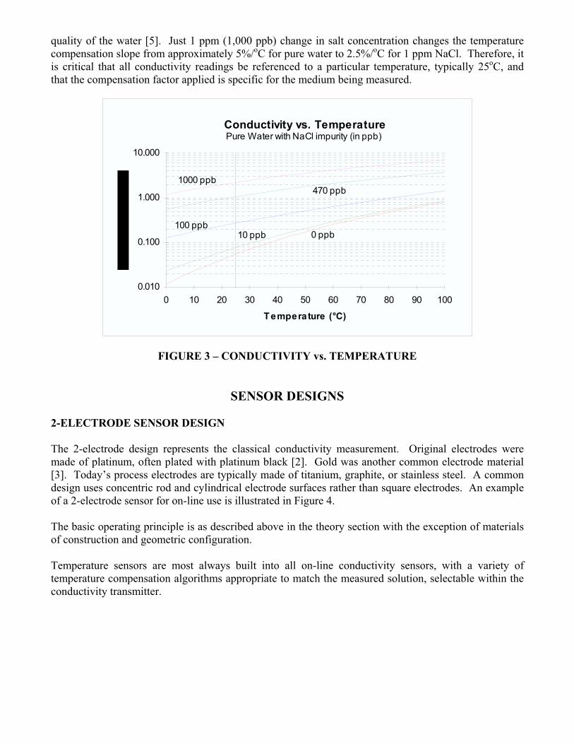
quality of the water [5]. Just 1 ppm (1,000 ppb) change in salt concentration changes the temperature
compensation slope from approximately 5%/oC for pure water to 2.5%/
oC for 1 ppm NaCl. Therefore, it
is critical that all conductivity readings be referenced to a particular temperature, typically 25oC, and
that the compensation factor applied is specific for the medium being measured.
Conductivity vs. Temperature
Temperature (°C)
0.010
0.100
1.000
10.000
0 10 20 30 40 50 60 70 80 90 100
0 ppb10 ppb100 ppb
470 ppb1000 ppb
Pure Water with NaCl impurity (in ppb)
FIGURE 3 – CONDUCTIVITY vs. TEMPERATURE
SENSOR DESIGNS
2-ELECTRODE SENSOR DESIGN
The 2-electrode design represents the classical conductivity measurement. Original electrodes were
made of platinum, often plated with platinum black [2]. Gold was another common electrode material
[3]. Today’s process electrodes are typically made of titanium, graphite, or stainless steel. A common
design uses concentric rod and cylindrical electrode surfaces rather than square electrodes. An example
of a 2-electrode sensor for on-line use is illustrated in Figure 4.
The basic operating principle is as described above in the theory section with the exception of materials
of construction and geometric configuration.
Temperature sensors are most always built into all on-line conductivity sensors, with a variety of
temperature compensation algorithms appropriate to match the measured solution, selectable within the
conductivity transmitter.

FIGURE 4 – CONCENTRIC 2-ELECTRODE DESIGN
OUTER ELECTRODE
CYLINDER
INNNER
ELECTRODE
ROD
2-electrode Sensor Considerations – The 2-electrode design excels in applications of low conductivity
solutions. The well defined cell geometry and the high solution resistance allow for very accurate and
precise conductivity determination.
Polarization can still occur to an appreciable degree at high ionic concentrations even with the use of an
AC voltage. While the range of application is dependent on the cell constant and transmitter used, 2-
electrode sensors are typically applied to conductivity measurements not greater 1,000-10,000 uS/cm.
Also, the cell resistance measured is the total of the solution plus any resistive coatings on the electrode
surfaces. Therefore, resistive coating on the electrode surface will directly affect the reading.
4-ELECTRODE SENSOR DESIGN
The 4-electrode sensor design is illustrated in Figure 5. An AC voltage is applied across the 2 outside
electrodes as with the 2-electrode sensor. However, rather than directly measuring the current between
these 2 electrodes, the principle of the 4-electrode sensor is to measure the voltage drop across the 2
inner electrodes [2]. Operating with a known current condition, "I", the cell resistance can be calculated
by rearrangement of Ohm’s law:
V = I R R = V/I
4-electrode Sensor Considerations – One limitation of the 2-electrode design is the polarization effect at
high concentrations. In the 4-electrode configuration, there is virtually no current flow at the inner
voltage sensing electrodes. Therefore, polarization does not occur, allowing the 4-electrode design to be
used at higher concentrations. A second benefit of the 4-electrode sensor is its tolerance of electrode
coating. Since the 4-electrode technique measures potential drop rather than resistance, the
measurement remains accurate, despite minor coating. Other advantages of the 4-electrode
design are its design permits easier in-process cleaning than 2-electrode designs, and that it can be
installed in smaller piping than inductive sensors.

FIGURE 5 4-ELECTRODE SENSOR DESIGN
INDUCTIVE SENSOR DESIGN
The next methodology differs substantially from the previous described methods. Due to the nature of
the measurement principle, the "inductive" design is also known by a variety of names including "non-
contacting" conductivity or "electrodeless" conductivity owing to the fact that there are no metallic
electrodes in contact with the solution. Given the sensor construction, it is also referred to as "toroidal"
conductivity.
The inductive conductivity sensor consists of two toroidal coils encapsulated in an inert polymer body
(PEEK, polypropylene, etc.) as shown in Figure 6. One coil is energized at a frequency of 10 kHz - 20
kHz, which, by means of electromagnetic principle, induces an electric field through the center bore of
the sensor [6, 7]. When placed in a conductive solution, a current loop is generated, which is then
sensed by the measurement toroid. The more conductive the medium, the more signal is transferred to
the second coil.
Inductive Sensor Considerations – The inductive design offers several major advantages over other
designs: since there are no metallic electrodes contact with the sample solution, corrosion is less of an
issue; there are no polarization effects; and the signal increases with decreasing resistance (as compared
to opposite with contacting electrodes). Also, to a great extent, the sensor is not affected by resistive
coatings on the sensor, including oils and grease.
An installation consideration is that the induced field extends several inches beyond the sensor body
itself. Therefore, typically larger piping is required for inductive sensors than contacting. If sufficient
clearance is not provided, the reading will be impacted. If the piping is non-conductive, the readings

will be low, if the piping is conductive, the readings will be high. This effect can be compensated by
calibrating the sensor in the configuration in which it will be used.
GENERATOR DETECTOR
INDUCED
CURRENT
FIGURE 6 – INDUCTIVE SENSOR DESIGN
APPLICATIONS
TYPES OF APPLICATIONS
There are two major types of applications where conductivity is used; either for detection of the
presence of an impurity, or, as determination of concentration of a specific chemical.
Perhaps the largest application of conductivity is during water purification. The presence of any ionic
contamination clearly can have a major impact on product as applied to semiconductor rinsing and water
for injection. Impurities in water used in industrial processing can raise concerns due to reduced
lifetime of resin beds, scale formation at heat exchangers and boilers, or undesirable flavors and odors in
food industry.
Rinsing stages in manufacturing processes can be optimized using conductivity measurement to assure
elimination of impurities while minimizing water consumption.
Another major class of applications involves determination of chemical concentration. It has been
discussed that conductivity is non-specific; unable to distinguish specifically which ions are present.
However, under controlled conditions, the presence of binary mixtures (1 chemical + water) is well
suited for concentration measurement and control.
Some specific examples of each of these types of applications and each conductivity sensor type are
presented below.
APPLICATION EXAMPLES
Water Preparation for Production – High purity water plays a key role in the production of quality
product across industries including chemical and industrial processing, food and beverage, and
bio/pharmaceutical. Conductivity is an ideal measurement parameter for detecting trace impurities
throughout the water purification stages including measuring incoming water, monitoring efficiency of
ultra-filtration and reverse osmosis units or ion-exchangers. The 2-electrode sensor provides the high
accuracy and sensitivity required in these installations, and there is no concern for dirty particles coating
the sensor.
CIP Chemical Control – A common practice in the Food and Beverage industry is to Clean In Place
(CIP) process piping and vessels by pumping sodium hydroxide through the process. Typically, bulk
chemicals are stored at a high concentration, 40-45%, and then diluted to the required concentration,
typically 3-5%. This represents a binary mixture of sodium hydroxide and water, and over this range,
there is a significant change in conductivity (refer to Figure 2) making it a sensitive, fast responding
detector. Therefore, this dilution step can be controlled by applying feedback control from a
conductivity measurement system. Also, in the process lines, conductivity is commonly used for
interface detection. The lines are sequentially flushed with cleaning agents, caustic, and water.
Conductivity senses when the caustic is sufficiently flushed from lines and ready for process. Due the
high conductivity of the caustic, a requirement for hygienic and sterilizable design, and preference to
keep piping size small, the 4-electrode is the sensor of choice.
Pulp and Paper Caustic Measurement – Caustic solutions including sodium hydroxide, sodium
carbonate, sodium sulfide and sodium hypochlorite are widely in the pulp and paper industry.
Hydroxide ions are far more conductive than its resulting neutralized salts. Therefore, conductivity is a
useful indication of sodium hydroxide concentration. Complex mixtures of chemicals minimize the
application of conductivity for absolute concentration measurement. Rather, it is a valuable tool for
monitoring trends in concentration of white liquor feeding digesters, recovering depleted black liquor, or
monitoring fiber rinsing efficiency. Inductive sensors are required due to the high concentration range,
the potential for precipitates and scaling, as well as fibers in solution.
CONCLUSION
The theory and measurement of electrolytic conductivity is more complex than simply two electrodes
immersed into solution. Conductivity has established a broad base of applications from ultrapure water,
to chemical concentration control, to wastewater monitoring despite the fact that conductivity is non-
specific. By knowing both the limitations and the capabilities of the methodology, coupled with
continued advances in hardware technology, the applications of electrolytic conductivity will continue to
expand over its third century of service.
REFERENCES
1. Stock, John T., "Two Centuries of Quantitative Electrolytic Conductivity", Analytical Chemistry,
vol. 6, (4), April, 1984, pp. 561-570.
2. Ewing, G.W., Analytical Instrumentation Handbook, 2nd
edition, M. Decker, New York, 1997, pp.
1099-1105.
3. Bender, Gary T., Principles of Chemical Instrumentation, Saunders Company, Philadelphia, PA,
1987, pp. 169-170.
4. Ewing, Galen Wood, Instrumental Methods of Chemical Analysis, McGraw-Hill, New York,
1985, pp. 332.
5. Internal Communication, Mettler-Toledo In gold.
6. McMillan, Gregory K.; Editor-in-Chief; Process/Industrial Instruments and Controls Handbook, 5th
Edition; McGraw-Hill; New York; (1999) pp. 6.14-6.23.
7. Light, T.S., “Conduct Electricity without Electrodes?” Chemtech, 20, (9), August, 1990, pp.496-
501.
8. Clesceri, Lenore S., "2510 Conductivity", Standard Methods for the Examination of Water and
Wastewater, 20th
ed., American Public Health Association, Washington, D.C., 1998, pp. 2-44 -2-
47.
9. Dreyfus, Robert H., "D 1125-95, Standard Test Methods for Electrical Conductivity and
Resistivity of Water", 2002 Annual Book of ASTM Standards, Vol. 11.01 Water (I), ASTM, West
Conshohocken, PA, 2002, pp. 85-91.