principles of blast cleaning - home - blast & … & final conditions: rust grade a...
TRANSCRIPT

PRINCIPLES OF BLAST
CLEANING
October 2013

AGENDA
In the next 45 to 50 minutes.........................
• Blast cleaning – application basics
• Initial and final conditions of new steel - significance
• Types of media propulsion
• Elements of a blast cleaning machine
• Wheel parts and hot spots
• Process parameters affecting blast quality
• Operating cost elements - wheel and airblast systems
• Blast media information, its effect on cleaning and operating mix
• Introduction to shot peening – comparison with blast cleaning

Blast Cleaning - Purpose
BLAST CLEANING
Purpose Remove rust, scale and prepare surface prior to downstream coating
Application
Carried out on most metallic components
Result Enhances life of coating, cosmetic finish
Process Control
Etching, De-burring & other special processes
Quality / Measurement
Generally visual to standards or preference

Blast Cleaning – what do you need to know about the application?
What do you need to know?
• Are we blast cleaning or shot peening?
• What is the initial condition of the steel component?
• What is the final desired outcome?
• Has the part ever been shot blasted – if not, did an alternate process
work?

Blast Cleaning – Impact Energy
Kinetic or Impact Energy
= ½ x mass of abrasive x square of velocity
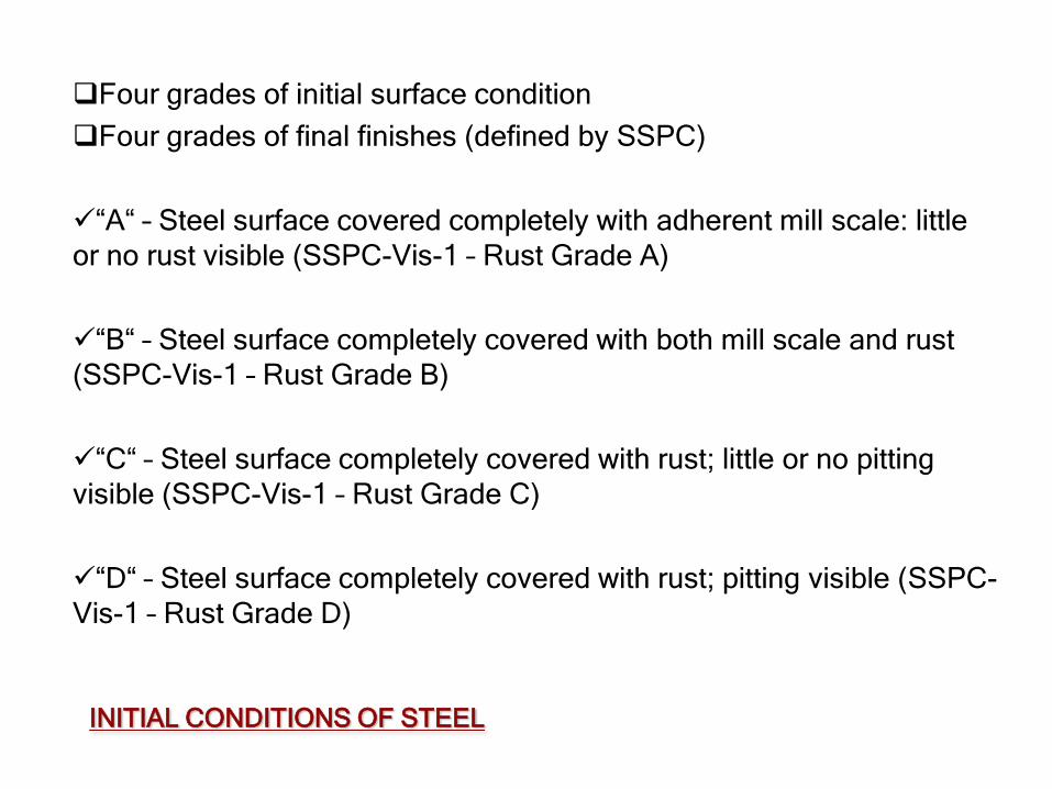
Four grades of initial surface condition
Four grades of final finishes (defined by SSPC)
“A“ – Steel surface covered completely with adherent mill scale: little
or no rust visible (SSPC-Vis-1 – Rust Grade A)
“B“ – Steel surface completely covered with both mill scale and rust
(SSPC-Vis-1 – Rust Grade B)
“C“ – Steel surface completely covered with rust; little or no pitting
visible (SSPC-Vis-1 – Rust Grade C)
“D“ – Steel surface completely covered with rust; pitting visible (SSPC-
Vis-1 – Rust Grade D)
INITIAL CONDITIONS OF STEEL

INITIAL & FINAL CONDITIONS: RUST GRADE A
•“A“ – Steel surface covered
completely with adherent mill scale:
little or no rust visible (SSPC-Vis-1 –
Rust Grade A)
•These are the TWO levels of surface
preparation recognized by SSPC in
(SSPC-Vis-1 – Rust Grade A):
•SSPC VIS 1, Guide & Reference Photographs
for Steel Surfaces Prepared by Dry Abrasive
Blast Cleaning.
SP 5 (White Metal) SP 10 (Near White)

INITIAL & FINAL CONDITIONS: RUST GRADE B
•“B“ – Steel surface completely
covered with both mill scale and rust
(SSPC-Vis-1 – Rust Grade B)
•These are the FOUR levels of surface
preparation recognized by SSPC
(SSPC-Vis-1 – Rust Grade B):
SP 5 (White Metal)
•SSPC VIS 1, Guide & Reference Photographs
for Steel Surfaces Prepared by Dry Abrasive
Blast Cleaning.
SP 10 (Near White) SP 10 (Commercial) SP 7 (Brush)

INITIAL & FINAL CONDITIONS: RUST GRADE C
SP 5 (White Metal)
•SSPC VIS 1, Guide & Reference Photographs
for Steel Surfaces Prepared by Dry Abrasive
Blast Cleaning.
SP 10 (Near White) SP 10 (Commercial) SP 7 (Brush)
•“C“ – Steel surface completely
covered with rust; little or not pitting
visible (SSPC-Vis-89 – Rust Grade C)
•These are the FOUR levels of surface
preparation recognized by SSPC
(SSPC-Vis-89 – Rust Grade C) :

INITIAL & FINAL CONDITIONS: RUST GRADE D
SP 5 (White Metal)
•SSPC VIS 1, Guide & Reference Photographs
for Steel Surfaces Prepared by Dry Abrasive
Blast Cleaning.
SP 10 (Near White) SP 10 (Commercial) SP 7 (Brush)
•“D“ – Steel surface completely
covered with rust; pitting visible
(SSPC-Vis-89 – Rust Grade D)
•These are the FOUR levels of surface
preparation recognized by SSPC
(SSPC-Vis-89 – Rust Grade D):

Why do contamination & finish requirement matter?
Total Power Required = Speed (FPM) x width of work / factor
Factor Cleaning Quality SSPC Profile
0.5 to 0.6 sq.ft./min./HP White Metal SSPC SP5
0.8 to 1.0 sq.ft./min./HP Near White SSPC SP10
1.5 sq.ft./min./HP Commercial SSPC SP6
1.8 sq.ft./min./HP Brush-off SSPC SP7

Two main types of media propulsion
• Propels abrasive by centrifugal
force through controlled blast
pattern and direction
• Blast media is pressurized in a
blast tank and propelled through
a nozzle or multiple nozzles
Airblast
Wheelblast
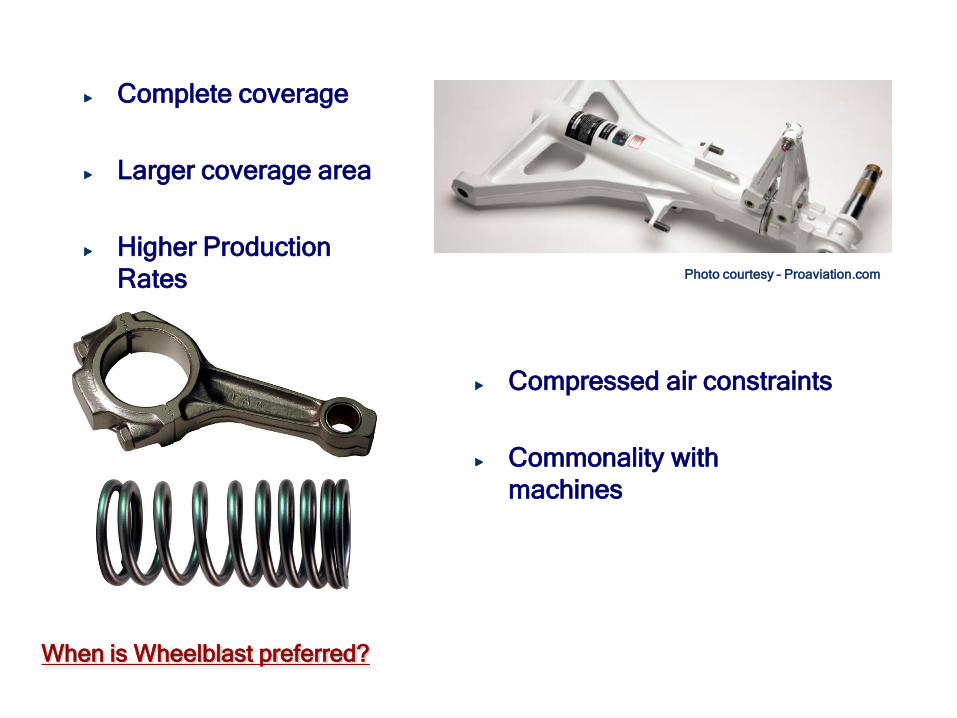
When is Wheelblast preferred?
Complete coverage
Larger coverage area
Higher Production
Rates
Compressed air constraints
Commonality with
machines
Photo courtesy – Proaviation.com

When is Airblast preferred?
Intricate Areas
Non-metallic media
Holes, Slots and Bores
Targeted areas on part
Flexibility of stand-off
distance
Thin wall sections
Ease of automation

Airblast and Wheelblast applications
Typical parts processed in a Wheelblast machine
Typical parts processed in an airblast machine
Typical Components: AIRBLAST & WHEELBLAST

Wheel Blast Machine – Elements
Five Basic Elements in a Wheelblast Machine

Wheel Blast Machine – Elements

COMPONENTS OF A BLAST WHEEL
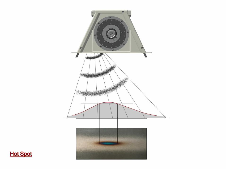
Hot Spot

Hot Spot
Hot Spot
Blast Pattern Test Sheet
Headings Tailings

Power Requirement of Wheel and Air systems
Comparison of media propulsion types
For abrasive flow of 2100 Lbs per minute
•21 operators
•½” nozzles
•Compressed air consumption 350 ft³/min per nozzle
•Compressor power 1400 kW
OR
4 wheels 20 HP each
80 HP (60 KW)
Energy factor 24 !!!

Wheelblast – Pros and Cons
Advantages:
• Velocity of shot easily controlled through wheel speed.
• High flow rate of abrasive will provide high production.
• Economical – one wheel can throw 300 lbs per minute with a 15 HP wheel equal to five 3/8” nozzles at direct pressure at 80 psi at a power requirement of 190 HP.
• Self contained unit does not require a compressor.
Disadvantages:
• Can only use metallic media.
• Can damage delicate parts.
• Not good for localized peening.
• Greater abrasive consumption.

Factors affecting Shot Blasting process
Factors affecting the Shot Blasting process
•Initial condition of the component – material and contamination
•Velocity of abrasive
•Size (and shape) of abrasive
•Hardness of abrasive
•Blast wheel location
•Travel speed of part through the machine (cycle time / exposure time)
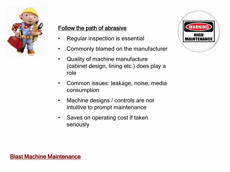
Blast Machine Maintenance
Follow the path of abrasive
• Regular inspection is essential
• Commonly blamed on the manufacturer
• Quality of machine manufacture
(cabinet design, lining etc.) does play a
role
• Common issues: leakage, noise, media
consumption
• Machine designs / controls are not
intuitive to prompt maintenance
• Saves on operating cost if taken
seriously

Elements of Operating Cost - Wheelblast
Operating Cost Elements
•Primary heads - Wheelblast
•Electricity (total connected load x cost of power)
•Media consumption / replenishment (total media flow x breakdown rate)
•Cost of wheel parts – wheel parts
•Cabinet and other component wear – liners, bearings, elevator belt & buckets,
dust collector cartridges etc.
•Wear on work handling arrangement components – table, rollers, belts etc.

Elements of Operating Cost - Airblast
Operating Cost Elements
•Primary heads - Airblast
•Electricity (total connected load x cost of power) – to operate compressor
•Media consumption / replenishment (total media flow x breakdown rate)
•Cost of wear parts – nozzle, hoses, tank valves etc.
•Cabinet and other component wear – liners, bearings, elevator belt & buckets,
dust collector cartridges etc.
•Wear on work handling arrangement components – table, rollers, belts etc.

BLAST MEDIA SIZES
Information courtesy:
Ervin Industries

Peening Parameters – Media size, shape and type
• Media size, shape
and type
• Most commonly
used peening
media
• Manufactured to
AMS
specifications
Source: ervinindustries.com

Media: Shot vs. Grit
1st Choice = Smallest Effective Shot
Flow: Volume in Pounds per Minute
1st Choice = Highest Usable Amount
Speed: Velocity at Blade Tip in FPS
1st Choice = Lowest Effective FPS
Blast Media Selection

Media size and cleaning
BLAST MEDIA SPECIFICATIONS
Too small
Scale
Base metal
Scale
Base metal
Too big
Scale
Base metal
Balanced operating mix

SHOT SIZE & COUNT
Abrasive Size Nominal Average number of pellets
Dimensions per pound of shot
inches
S-70 0.007 12,000,000
S-110 0.0117 3,390,000
S-170 0.0165 1,200,000
S-230 0.0232 420,000
S-280 0.028 250,000
S-330 0.0331 152,000
S-390 0.0394 93,000
S-460 0.0469 54,000
S-550 0.0555 32,000
S-660 0.0661 19,000
S-780 0.0787 11,000
• For a given mass (steel
shot), impact power
delivered to the work
varies as the square of
a change in velocity
• Weight or mass of a
sphere varies as a
cube of its diameter.

ROUGHNESS MEASUREMENTS
The profile depth (or height) is dependent on the size, type, hardness of abrasive, particle velocity and angle of impact

Conditioned Cut Wire - Media size, shape and type
• Cut wire
• Blasting Applications - HRC 45-
50;
• Shot Peening high strength parts
HRC 55-60
• Shot Peening softer parts - HRC
50-55
Advantages:
Improved consistency
Highest durability
Dust generation
Surface contamination
Improved part fatigue resistance
Source: premiershot.com

Blast Cleaning and Shot Peening
BLAST CLEANING SHOT PEENING
Purpose Remove rust, scale and prepare surface prior to downstream coating
Induce compressive residual stress and enhance useful life
Application
Carried out on most metallic components
Generally on components that undergo cyclic loading
Result Enhances life of coating, cosmetic finish
Part of maintenance procedure
Process Control
Etching, De-burring & other special processes
Quantifiable & measurable
Quality / Measurement
Generally visual to standards or preference
Specification driven

Fundamentals of Peening - Intensity
Photo courtesy – Electronics Inc.
Process to increase resistance to fatigue
fracture of a part that undergoes cyclic
loading.
Peening intensity is measured by
deflection of a piece of spring steel called
‘Almen Strip’
Almen intensity is a measurable
representation of the compressive
stresses induced in the peened part
Ferrous peening media: steel shot,
conditioned cut wire; Non-ferrous: glass
bead and ceramic

INTENSITY MEASUREMENT PROCEDURE
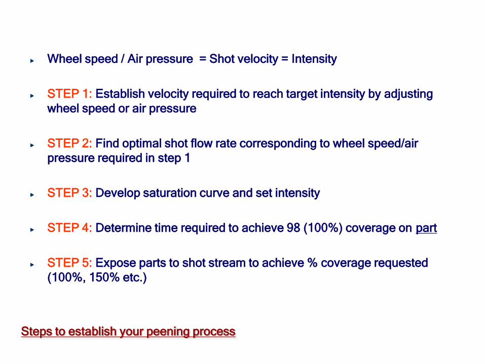
Steps to establish your peening process
Wheel speed / Air pressure = Shot velocity = Intensity
STEP 1: Establish velocity required to reach target intensity by adjusting
wheel speed or air pressure
STEP 2: Find optimal shot flow rate corresponding to wheel speed/air
pressure required in step 1
STEP 3: Develop saturation curve and set intensity
STEP 4: Determine time required to achieve 98 (100%) coverage on part
STEP 5: Expose parts to shot stream to achieve % coverage requested
(100%, 150% etc.)

Cleaning and Peening - Comparison
Media velocity
Media size
Media shape
Measurement of
results
Monitoring of
results and
reporting
inconsistencies
No monitoring
Inconsistency not
an issue
Not critical
Visual only
For critical etching
applications only
Measurement and
monitoring required
Consistency critical
Consistency critical
Need to be carried
out regularly
Specification driven

Cleaning and Peening – Comparison - Media
Blast Cleaning Steel shot (carbon & stainless) Steel grit Zinc shot / cut wire Shot / grit mix (operating mix) Shot size mix (operating mix) Non-ferrous – glass bead, ceramic, aluminum oxide Organic – corn cob, walnut shell Consistency of shot size and shape is not critical
• Shot Peening
• Steel shot
• Conditioned cut wire
• Glass bead
• Ceramic
• Consistency of shot size,
shape very critical for
repeatable peening results