principles of breast tomosynthesis acquisition …...1 principles of breast tomosynthesis...
TRANSCRIPT
1
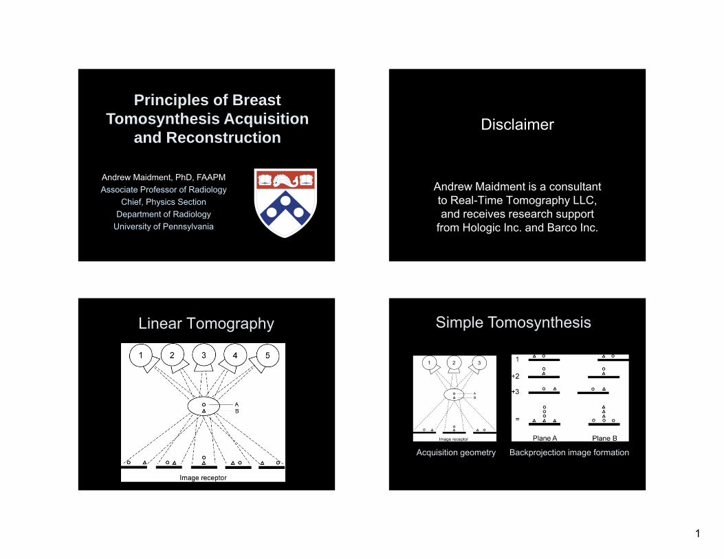
Principles of BreastTomosynthesis Acquisition
and Reconstruction
Andrew Maidment, PhD, FAAPMAssociate Professor of Radiology
Chief, Physics SectionDepartment of Radiology
University of Pennsylvania
Disclaimer
Andrew Maidment is a consultant to Real-Time Tomography LLC, and receives research support
from Hologic Inc. and Barco Inc.
Linear Tomography Simple Tomosynthesis
Acquisition geometry Backprojection image formation
2
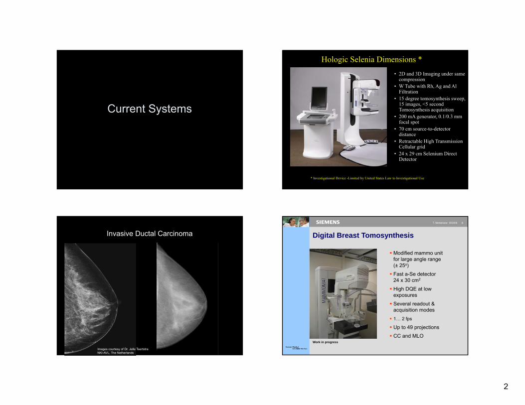
Current Systems
Hologic Selenia Dimensions *
* Investigational Device -Limited by United States Law to Investigational Use
• 2D and 3D Imaging under same compression
• W Tube with Rh, Ag and Al Filtration
• 15 degree tomosynthesis sweep, 15 images, <5 second Tomosynthesis acquisition
• 200 mA generator, 0.1/0.3 mm focal spot
• 70 cm source-to-detector distance
• Retractable High Transmission Cellular grid
• 24 x 29 cm Selenium Direct Detector
Invasive Ductal Carcinoma
Images courtesy of Dr. Jelle Teertstra NKI-AVL, The Netherlands
8T. Mertelmeier 05/2006
Digital Breast Tomosynthesis
Work in progress
Modified mammo unitfor large angle range (± 25o)
Fast a-Se detector 24 x 30 cm2
High DQE at lowexposures
Several readout & acquisition modes
1… 2 fps
Up to 49 projections
CC and MLO

3
9T. Mertelmeier 05/2006
Human subject
Age 68 MLO position6 cm compressed
28 kVp, W/Rh 133 mAs49 projections 39 s scan1 mm slices
scar (benign biopsy 1980)invasive ductal CA with lobular component
Image data Duke University, Dr. Jay Baker
Proc SPIE 5745, 529-540 (2005)
slice at z = 21 mm above patient tableslice close to the surface of the breast
Doc. No/Page 10(xx)2007-xx-xx/Signature
Photon Counting Tomosynthesis
Work in progress
Doc. No/Page 11(xx)2007-xx-xx/Signature
Doc. No/Page 11(xx)
2007-xx-xx/Signature
Geometry
• One sweep 3D data
• Multi-slit photon counting: no electronic noise, no ghosting, no scattered radiation
4
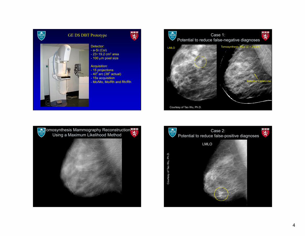
GE DS DBT Prototype
Detector:- a-Si (CsI) - 23×19.2 cm2 area- 100 m pixel size
Acquisition: - 15 projections- 40o arc (38o actual) - 15s acquisition- Mo/Mo, Mo/Rh and Rh/Rh
Case 1: Potential to reduce false-negative diagnoses
Invasive Carcinoma
LMLO Tomosynthesis Slice (Z = 24mm)
Courtesy of Tao Wu, Ph.D.
Tomosynthesis Mammography Reconstruction Using a Maximum Likelihood Method
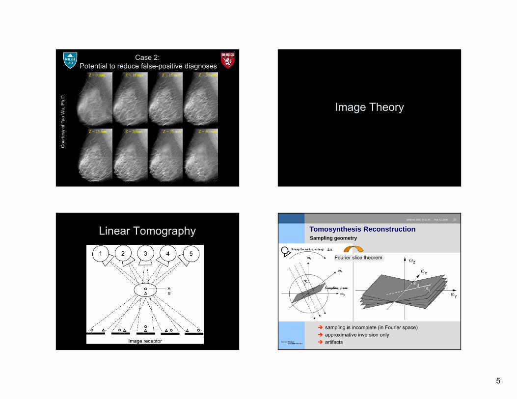
Case 2: Potential to reduce false-positive diagnoses
LMLO
Cou
rtesy
of T
ao W
u, P
h.D
.
5
Case 2: Potential to reduce false-positive diagnoses
Z = 0 mm Z = 10 mm Z = 15 mm Z = 20 mm
Z = 25 mm Z = 30mm Z = 35 mm Z = 40 mm
Cou
rtesy
of T
ao W
u, P
h.D
.
Image Theory
Linear Tomography20SPIE MI 2006 6142-15 Feb 12,.2006
Tomosynthesis ReconstructionSampling geometry
sampling is incomplete (in Fourier space) approximative inversion only artifacts
±
Fourier slice theorem
6
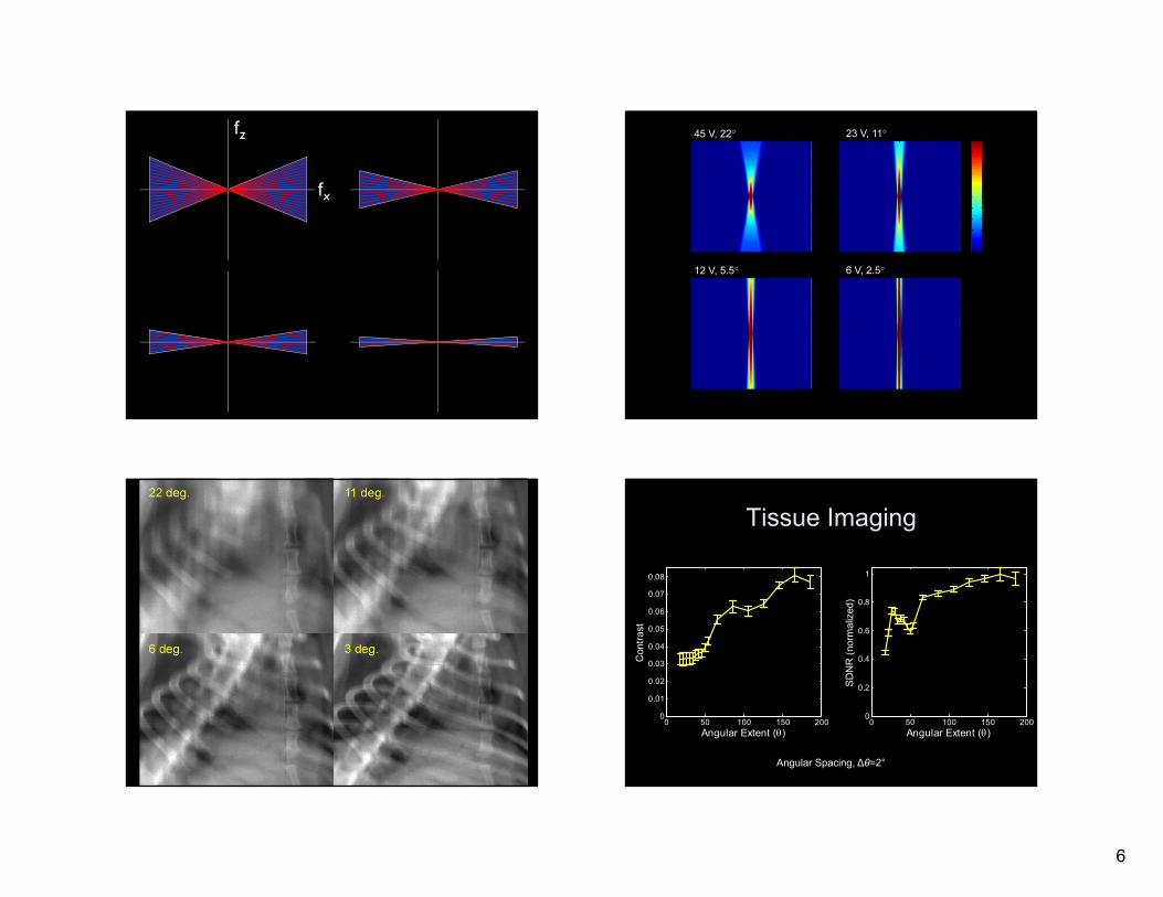
fz
fx
45 V, 22° 23 V, 11°
12 V, 5.5° 6 V, 2.5°
Tissue Imaging
0 50 100 150 2000
0.01
0.02
0.03
0.04
0.05
0.06
0.07
0.08
Angular Extent ()
Con
trast
0 50 100 150 2000
0.2
0.4
0.6
0.8
1
Angular Extent ()
SDN
R (n
orm
aliz
ed)
Angular Spacing, ∆θ=2°
7
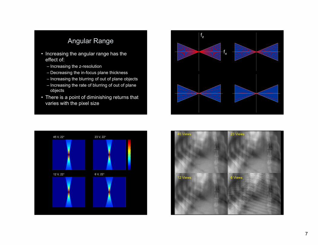
Angular Range
• Increasing the angular range has the effect of:– Increasing the z-resolution– Decreasing the in-focus plane thickness– Increasing the blurring of out of plane objects– Increasing the rate of blurring of out of plane
objects• There is a point of diminishing returns that
varies with the pixel size
fz
fx
45 V, 22° 23 V, 22°
12 V, 22° 6 V, 22°
8
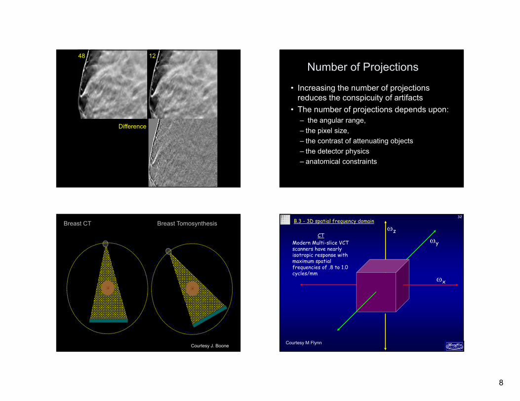
48 12
Difference
Number of Projections
• Increasing the number of projections reduces the conspicuity of artifacts
• The number of projections depends upon:– the angular range, – the pixel size, – the contrast of attenuating objects– the detector physics– anatomical constraints
Breast CT Breast Tomosynthesis
Courtesy J. Boone
32B.3 - 3D spatial frequency domain
CTModern Multi-slice VCT scanners have nearly isotropic response with maximum spatial frequencies of .8 to 1.0 cycles/mm
z
x
y
Courtesy M Flynn
9
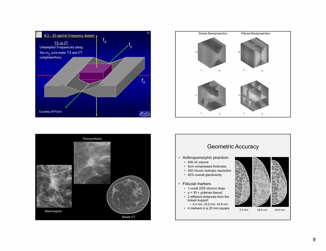
33B.3 - 3D spatial frequency domain
TS vs CTUnsampled frequencies along the y axis make TS and CT complimentary.
fz
fx
fy
Courtesy M Flynn
Simple Backprojection Filtered Backprojection
296
Mammogram
Tomosynthesis
Breast CT
• Anthropomorphic phantom:• 450 ml volume• 5cm compressed thickness• 200 micron isotropic resolution• 40% overall glandularity
• Fiducial markers • 1-voxel (200 micron) large• μ = 30 × μ(dense tissue)• 3 different distances from the
breast support • 6.4 mm, 25.6 mm, 44.8 mm
• 4 markers in a 20 mm square
Geometric Accuracy
6.4 mm 25.6 mm 44.8 mm
10
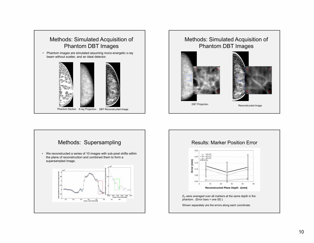
• Phantom images are simulated assuming mono-energetic x-ray beam without scatter, and an ideal detector.
Phantom Section DBT Reconstructed ImageX-ray Projection
Methods: Simulated Acquisition of Phantom DBT Images
Methods: Simulated Acquisition of Phantom DBT Images
Reconstructed ImageDBT Projection
Methods: Supersampling
• We reconstructed a series of 10 images with sub-pixel shifts within the plane of reconstruction and combined them to form a supersampled image.
6.1 6.2 6.3 6.4 6.5 6.6 6.7 6.81
1.5
2
2.5
3
3.5
4x 10
4
x (mm) from Chest Wall
Supe
rsam
pled
reco
nstru
cted
Imag
e In
tens
ity
6.52 6.53 6.54 6.55 6.56 6.571.5
2
2.5
3x 10
4
x (mm) from Chest Wall
Supe
rsam
pled
reco
nstru
cted
Imag
e In
tens
ity
Results: Marker Position Error
0.00
0.05
0.10
0.15
0.20
0.25
0 10 20 30 40 50
Reconstructed Plane Depth z(mm)
Erro
r (m
m)
(xC-xT)(yC-yT)(zC-zT)Ep
EP were averaged over all markers at the same depth in the phantom. (Error bars = one SD.)
Shown separately are the errors along each coordinate.
11
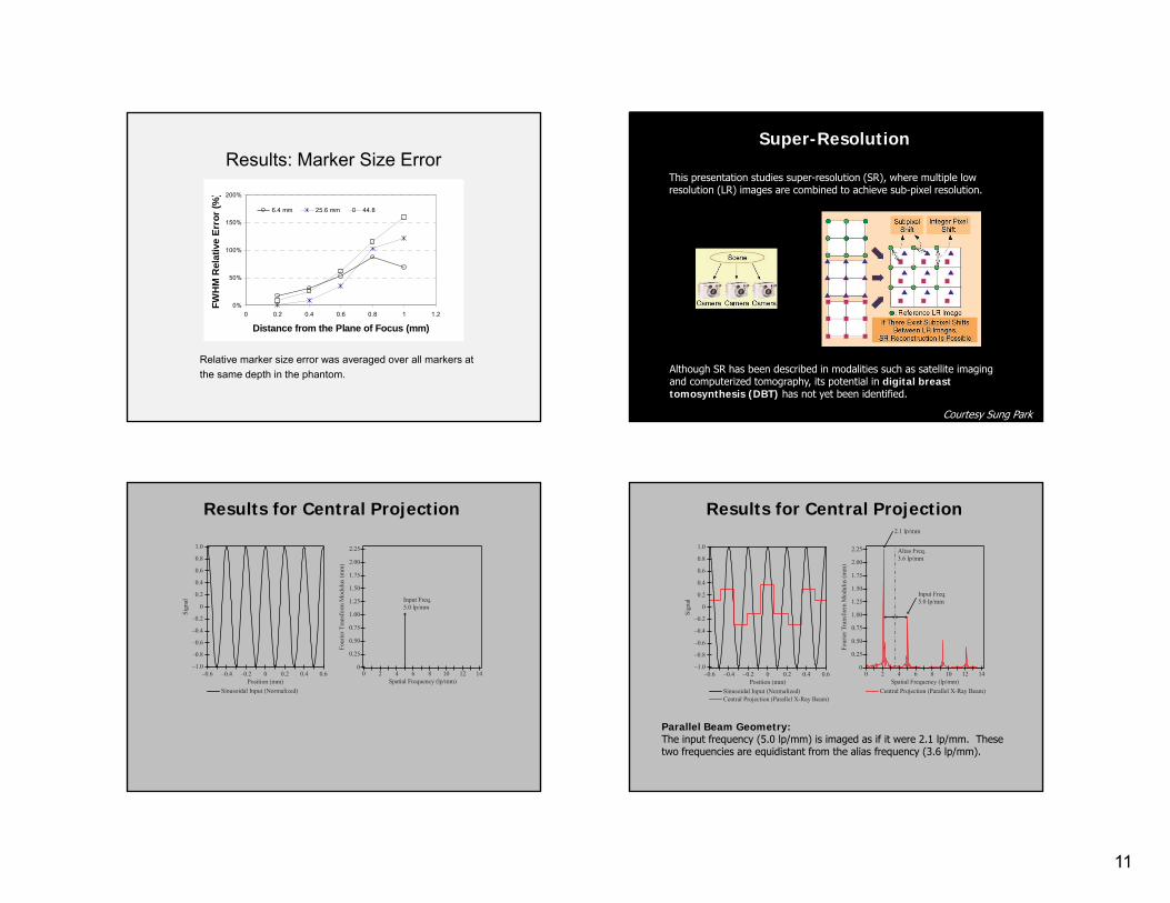
Results: Marker Size Error
Relative marker size error was averaged over all markers at the same depth in the phantom.
0%
50%
100%
150%
200%
0 0.2 0.4 0.6 0.8 1 1.2
Distance from the Plane of Focus (mm)
FWH
M R
elat
ive
Erro
r (%
)6.4 mm 25.6 mm 44.8
Super-Resolution
This presentation studies super-resolution (SR), where multiple low resolution (LR) images are combined to achieve sub-pixel resolution.
Courtesy Sung Park
Although SR has been described in modalities such as satellite imaging and computerized tomography, its potential in digital breast tomosynthesis (DBT) has not yet been identified.
Results for Central Projection
–0.6–1.0
–0.8
Position (mm)
Sign
al
–0.4 –0.2 0 0.2 0.4 0.6
–0.6
–0.4
–0.2
0
0.2
0.4
0.6
0.8
1.0
Sinusoidal Input (Normalized)
00
0.25
Spatial Frequency (lp/mm)
Four
ierT
rans
form
Mod
ulus
(mm
)
2 4 6 8 10 12
0.50
0.75
1.00
1.25
1.50
1.75
2.00
2.25
14
Input Freq.5.0 lp/mm
Results for Central Projection
Parallel Beam Geometry:The input frequency (5.0 lp/mm) is imaged as if it were 2.1 lp/mm. These two frequencies are equidistant from the alias frequency (3.6 lp/mm).
–0.6–1.0
–0.8
Position (mm)Si
gnal
–0.4 –0.2 0 0.2 0.4 0.6
–0.6
–0.4
–0.2
0
0.2
0.4
0.6
0.8
1.0
Sinusoidal Input (Normalized)Central Projection (Parallel X-Ray Beam)
00
0.25
Spatial Frequency (lp/mm)
Four
ierT
rans
form
Mod
ulus
(mm
)
2 4 6 8 10 12
0.50
0.75
1.00
1.25
1.50
1.75
2.00
2.25
Central Projection (Parallel X-Ray Beam)
14
Input Freq.5.0 lp/mm
2.1 lp/mm
Alias Freq.3.6 lp/mm
12
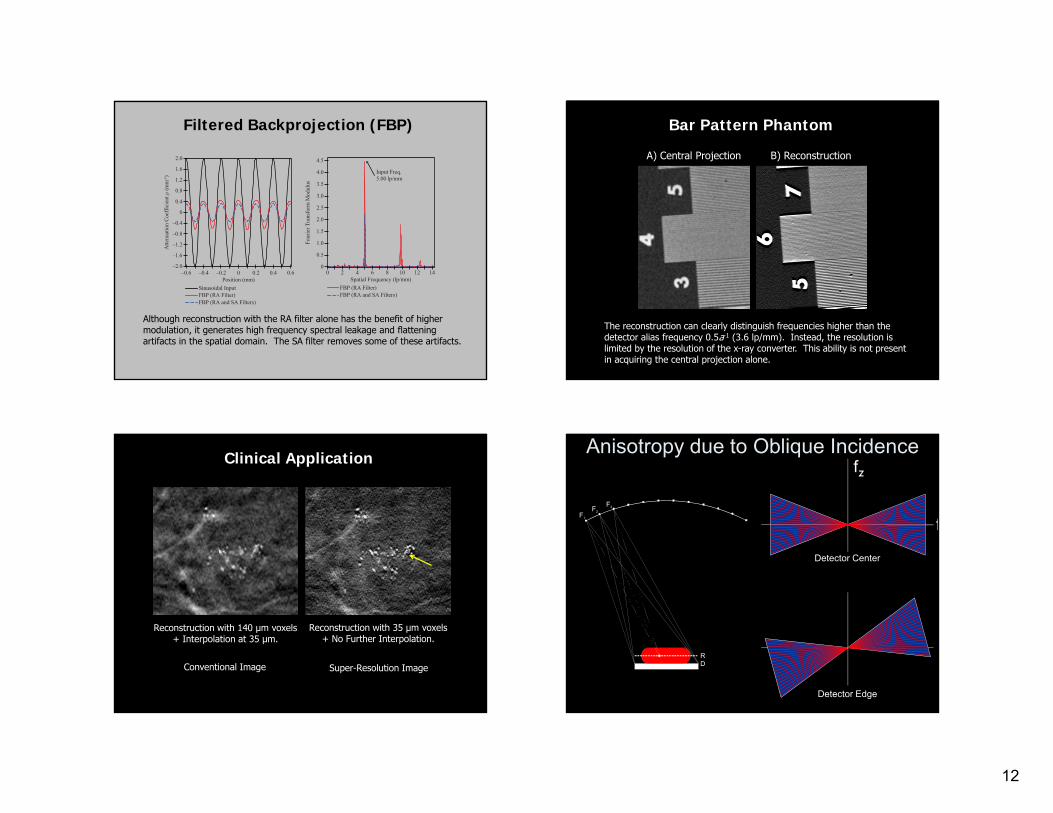
Filtered Backprojection (FBP)
Although reconstruction with the RA filter alone has the benefit of higher modulation, it generates high frequency spectral leakage and flattening artifacts in the spatial domain. The SA filter removes some of these artifacts.
–0.6–2.0
–1.6
Position (mm)
Atte
nuat
ion
Coef
ficie
ntμ
(mm
-1)
–0.4 –0.2 0 0.2 0.4 0.6
–1.2
–0.8
–0.4
0
0.4
0.8
1.2
1.6
2.0
Sinusoidal InputFBP (RA Filter)FBP (RA and SA Filters)
00
0.5
Spatial Frequency (lp/mm)
Four
ierT
rans
form
Mod
ulus
2 4 6 8 10 12
1.0
1.5
2.0
2.5
3.0
3.5
4.0
4.5
FBP (RA Filter)FBP (RA and SA Filters)
14
Input Freq.5.00 lp/mm
Bar Pattern Phantom
A) Central Projection B) Reconstruction
The reconstruction can clearly distinguish frequencies higher than the detector alias frequency 0.5a-1 (3.6 lp/mm). Instead, the resolution is limited by the resolution of the x-ray converter. This ability is not present in acquiring the central projection alone.
Clinical Application
Reconstruction with 140 μm voxels+ Interpolation at 35 μm.
Reconstruction with 35 μm voxels+ No Further Interpolation.
Conventional Image Super-Resolution Image
Anisotropy due to Oblique Incidencefz
fF1
F2
F3
DR
Detector Center
Detector Edge
13
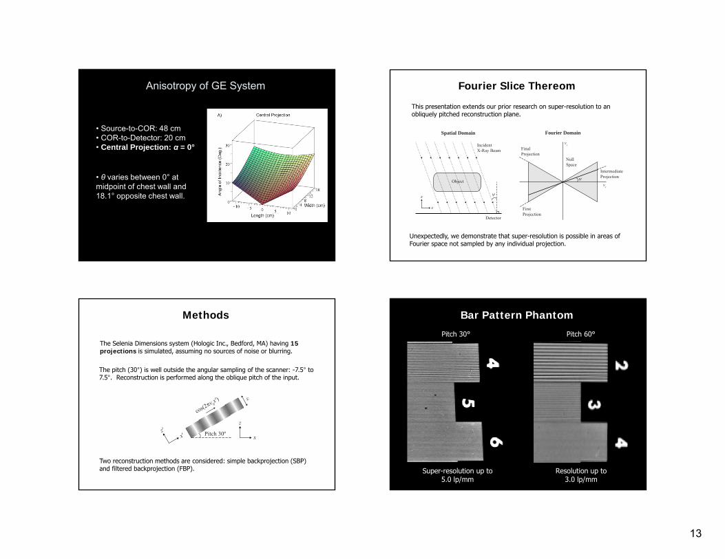
Anisotropy of GE System
• Source-to-COR: 48 cm• COR-to-Detector: 20 cm• Central Projection: α = 0°
• θ varies between 0° at midpoint of chest wall and 18.1° opposite chest wall.
Fourier Slice Thereom
Unexpectedly, we demonstrate that super-resolution is possible in areas of Fourier space not sampled by any individual projection.
This presentation extends our prior research on super-resolution to an obliquely pitched reconstruction plane.
νx
νz
ψ
FinalProjection
FirstProjection
IntermediateProjection
Detector
IncidentX-Ray Beam
Object
ψ
x
z
Spatial Domain Fourier Domain
NullSpace
The pitch (30°) is well outside the angular sampling of the scanner: -7.5° to 7.5°. Reconstruction is performed along the oblique pitch of the input.
Methods
The Selenia Dimensions system (Hologic Inc., Bedford, MA) having 15 projections is simulated, assuming no sources of noise or blurring.
Two reconstruction methods are considered: simple backprojection (SBP) and filtered backprojection (FBP).
ε
cos(2ν 0x′)
x
z
Pitch 30ºx′z′
Bar Pattern Phantom
Pitch 30° Pitch 60°
Super-resolution up to5.0 lp/mm
Resolution up to3.0 lp/mm
14
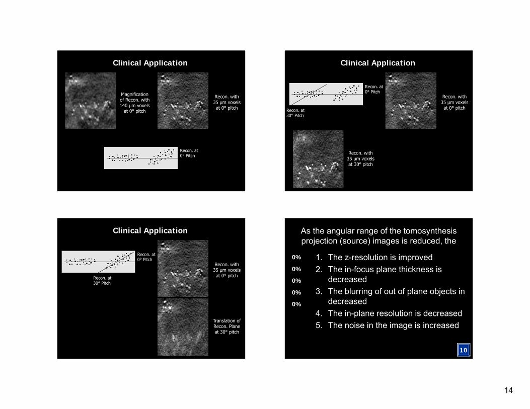
Clinical Application
Magnification of Recon. with 140 μm voxels
at 0° pitch
Recon. with 35 μm voxels at 0° pitch
Recon. at0° Pitch
Clinical Application
Recon. with 35 μm voxels at 0° pitch
Recon. with 35 μm voxels at 30° pitch
Recon. at30° Pitch
Recon. at0° Pitch
Clinical Application
Recon. with 35 μm voxels at 0° pitch
Translation of Recon. Plane at 30° pitch
Recon. at30° Pitch
Recon. at0° Pitch
As the angular range of the tomosynthesis projection (source) images is reduced, the
0%
0%
0%
0%
0%
10
1. The z-resolution is improved2. The in-focus plane thickness is
decreased3. The blurring of out of plane objects in
decreased4. The in-plane resolution is decreased5. The noise in the image is increased
15
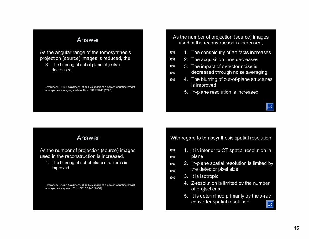
Answer
As the angular range of the tomosynthesis projection (source) images is reduced, the
3. The blurring of out of plane objects in decreased
References: A D A Maidment, et al, Evaluation of a photon-counting breast tomosynthesis imaging system, Proc. SPIE 5745 (2005).
As the number of projection (source) images used in the reconstruction is increased,
0%
0%
0%
0%
0%
10
1. The conspicuity of artifacts increases2. The acquisition time decreases3. The impact of detector noise is
decreased through noise averaging4. The blurring of out-of-plane structures
is improved5. In-plane resolution is increased
Answer
As the number of projection (source) images used in the reconstruction is increased,
4. The blurring of out-of-plane structures is improved
References: A D A Maidment, et al, Evaluation of a photon-counting breast tomosynthesis system, Proc. SPIE 6142 (2006).
With regard to tomosynthesis spatial resolution
0%
0%
0%
0%
0%
10
1. It is inferior to CT spatial resolution in-plane
2. In-plane spatial resolution is limited by the detector pixel size
3. It is isotropic4. Z-resolution is limited by the number
of projections5. It is determined primarily by the x-ray
converter spatial resolution
16
Answer
With regard to tomosynthesis spatial resolution
5. It is determined primarily by the x-ray converter spatial resolution
References: R J Acciavatti and A D A Maidment, Investigating the potential for super-resolution in digital breast tomosynthesis, Proc SPIE 7961 (2011).
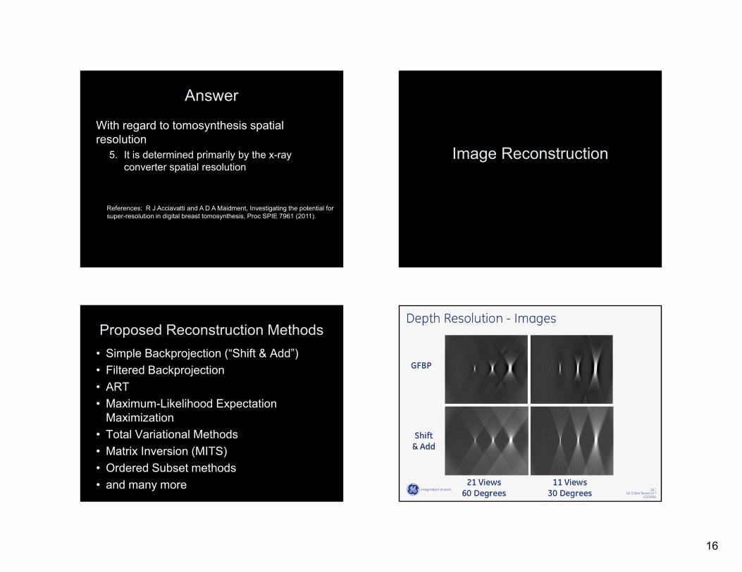
Image Reconstruction
Proposed Reconstruction Methods• Simple Backprojection (“Shift & Add”)• Filtered Backprojection• ART• Maximum-Likelihood Expectation
Maximization• Total Variational Methods • Matrix Inversion (MITS)• Ordered Subset methods• and many more
Tomo LSF
17
65T. Mertelmeier 05/2006
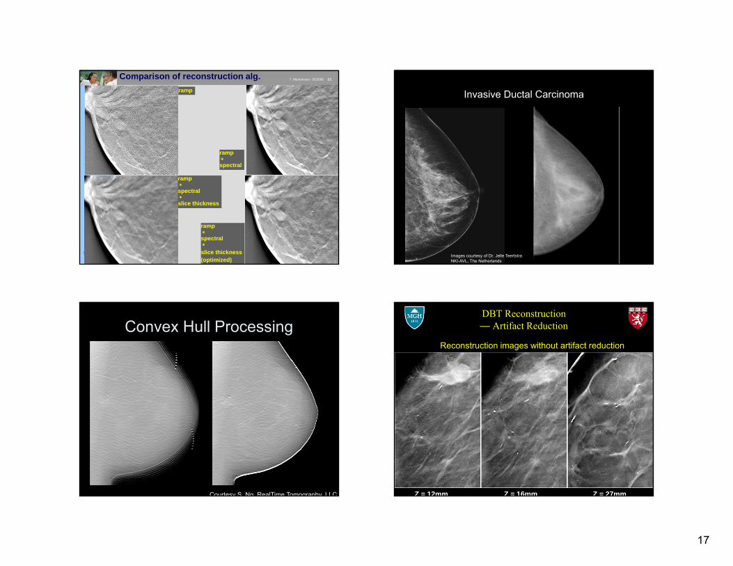
ramp
ramp
spectral
ramp
spectral
slice thickness
ramp
spectral
slice thickness(optimized)
Comparison of reconstruction alg.
Invasive Ductal Carcinoma
Images courtesy of Dr. Jelle Teertstra NKI-AVL, The Netherlands
Convex Hull Processing
Courtesy S. Ng, RealTime Tomography, LLC
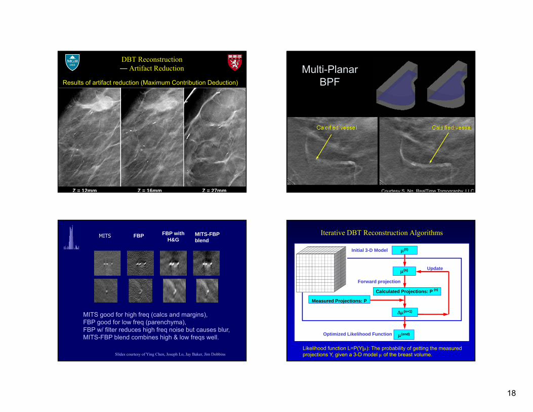
DBT Reconstruction — Artifact Reduction
Z = 16mm Z = 27mmZ = 12mm
Reconstruction images without artifact reduction
18
DBT Reconstruction — Artifact Reduction
Z = 16mm Z = 27mmZ = 12mm
Results of artifact reduction (Maximum Contribution Deduction)
Multi-PlanarBPF
Courtesy S. Ng, RealTime Tomography, LLC
MITS FBP FBP with H&G
MITS-FBP blend
Slides courtesy of Ying Chen, Joseph Lo, Jay Baker, Jim Dobbins
MITS good for high freq (calcs and margins),FBP good for low freq (parenchyma),FBP w/ filter reduces high freq noise but causes blur,MITS-FBP blend combines high & low freqs well.
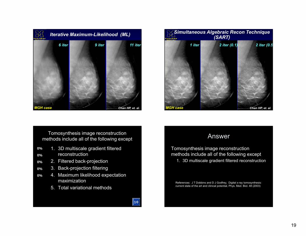
Iterative DBT Reconstruction Algorithms
(n)
(n+1)
Initial 3-D Model
Calculated Projections: P (n)
(end)
Forward projection
Update
Optimized Likelihood Function
Measured Projections: P
(0)
Likelihood function L=P(Y|): The probability of getting the measured projections Y, given a 3-D model of the breast volume.
19
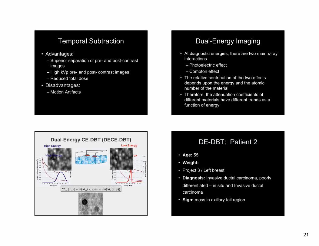
6 iter 9 iter 11 iter
Iterative Maximum-Likelihood (ML)
Chan HP, et. al.MGH case
1 iter 2 iter (0.5)2 iter (0.1)
Simultaneous Algebraic Recon Technique (SART)
Chan HP, et. al.MGH case
Tomosynthesis image reconstruction methods include all of the following except
0%
0%
0%
0%
0%
10
1. 3D multiscale gradient filtered reconstruction
2. Filtered back-projection3. Back-projection filtering4. Maximum likelihood expectation
maximization5. Total variational methods
Answer
Tomosynthesis image reconstruction methods include all of the following except
1. 3D multiscale gradient filtered reconstruction
References: J T Dobbins and D J Godfrey, Digital x-ray tomosynthesis: current state of the art and clinical potential, Phys. Med. Biol. 48 (2003)
20
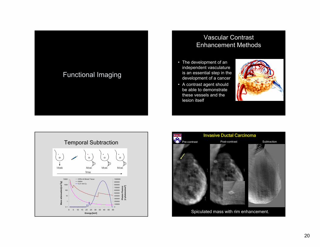
Functional Imaging
Vascular Contrast Enhancement Methods
• The development of an independent vasculature is an essential step in the development of a cancer
• A contrast agent should be able to demonstrate these vessels and the lesion itself
Temporal Subtraction
0.1
1
10
100
1000
10000
0 5 10 15 20 25 30 35 40 45 50
Energy [keV]
Mas
s at
tenu
atio
n[cm
2 /g]
0
100000
200000
300000
400000
500000
600000
700000
800000
900000
1000000
Phot
on F
luen
ce [#
pho
tons
/mm
2 ]
ICRU-44 Breast TissueIodine0.27 mm Cu
Post-contrastPre-contrast
Spiculated mass with rim enhancement.
Subtraction
Invasive Ductal Carcinoma
21
Temporal Subtraction
• Advantages:– Superior separation of pre- and post-contrast
images– High kVp pre- and post- contrast images– Reduced total dose
• Disadvantages:– Motion Artifacts
Dual-Energy Imaging
• At diagnostic energies, there are two main x-ray interactions– Photoelectric effect– Compton effect
• The relative contribution of the two effects depends upon the energy and the atomic number of the material
• Therefore, the attenuation coefficients of different materials have different trends as a function of energy
Dual-Energy CE-DBT (DECE-DBT)
Low Energy
High Energy Low Energy
High Energy
)),(ln()),(ln(),( yxSIwyxSIyxSI LtHDE
DE-DBT: Patient 2
• Age: 55
• Weight:• Project 3 / Left breast
• Diagnosis: Invasive ductal carcinoma, poorly
differentiated – in situ and Invasive ductal carcinoma
• Sign: mass in axillary tail region
22
DE
Temp 1 Temp2
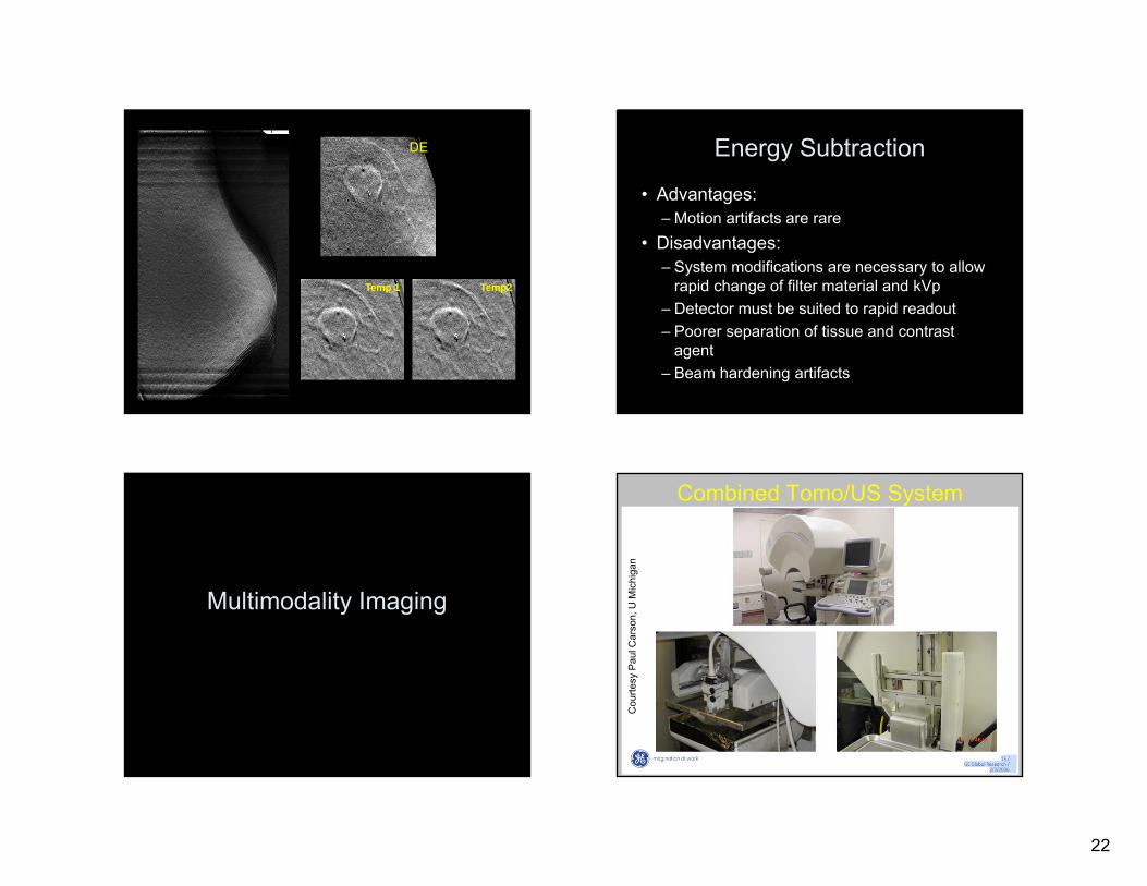
Energy Subtraction
• Advantages:– Motion artifacts are rare
• Disadvantages:– System modifications are necessary to allow
rapid change of filter material and kVp– Detector must be suited to rapid readout– Poorer separation of tissue and contrast
agent– Beam hardening artifacts
Multimodality Imaging
Combined Tomo/US System
Cou
rtesy
Pau
l Car
son,
U M
ichi
gan
23
PLC UoM / GE GR 6/5/06
Tomo with marked US
Cou
rtesy
Pau
l Car
son,
U M
ichi
gan
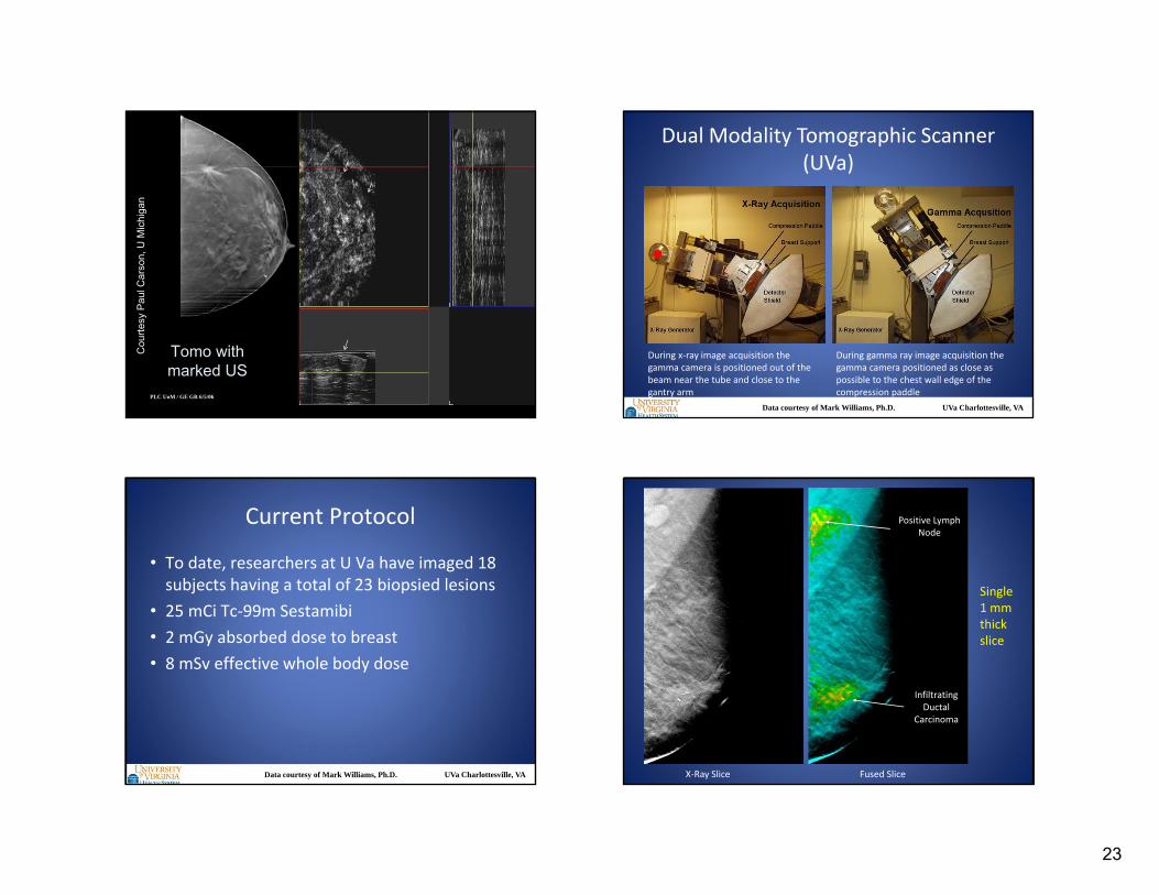
Dual Modality Tomographic Scanner (UVa)
During x‐ray image acquisition the gamma camera is positioned out of the beam near the tube and close to the gantry arm
During gamma ray image acquisition the gamma camera positioned as close as possible to the chest wall edge of the compression paddle
Data courtesy of Mark Williams, Ph.D. UVa Charlottesville, VA
Current Protocol
• To date, researchers at U Va have imaged 18 subjects having a total of 23 biopsied lesions
• 25 mCi Tc‐99m Sestamibi• 2 mGy absorbed dose to breast• 8 mSv effective whole body dose
Data courtesy of Mark Williams, Ph.D. UVa Charlottesville, VA
Positive Lymph Node
Infiltrating Ductal
Carcinoma
X‐Ray Slice Fused Slice
Single 1 mm thick slice
24
Advantages of tomosynthesis
• Improves conspicuity by removing overlying structures
• Permits section imaging with high resolution in coronal view and limited MPR
• Easily performed on the high volume of radiography patients
• Lower radiation dose compared with CT • Lower cost compared with CT