principles of retarders - meadowlark optics | … · polarization components and produces a phase...
TRANSCRIPT
Tel (303) 833 -4333 • Fax (303) 833 -4335 • web s i t e : www.meadowla rk . com
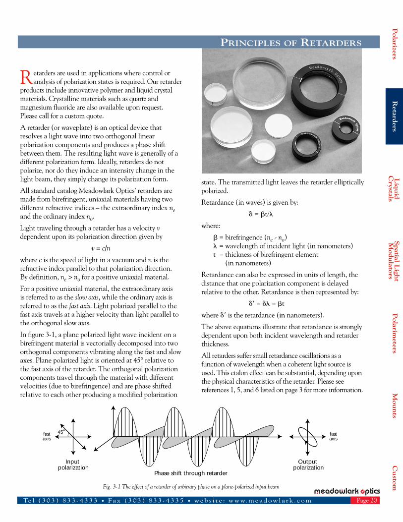
Retarders are used in applications where control oranalysis of polarization states is required. Our retarder
products include innovative polymer and liquid crystalmaterials. Crystalline materials such as quartz andmagnesium fluoride are also available upon request. Please call for a custom quote.
A retarder (or waveplate) is an optical device thatresolves a light wave into two orthogonal linearpolarization components and produces a phase shiftbetween them. The resulting light wave is generally of adifferent polarization form. Ideally, retarders do notpolarize, nor do they induce an intensity change in thelight beam, they simply change its polarization form.
All standard catalog Meadowlark Optics’ retarders aremade from birefringent, uniaxial materials having twodifferent refractive indices – the extraordinary index neand the ordinary index no.
Light traveling through a retarder has a velocity vdependent upon its polarization direction given by
v = c/n
where c is the speed of light in a vacuum and n is therefractive index parallel to that polarization direction. By definition, ne > no for a positive uniaxial material.
For a positive uniaxial material, the extraordinary axis is referred to as the slow axis, while the ordinary axis isreferred to as the fast axis. Light polarized parallel to thefast axis travels at a higher velocity than light parallel tothe orthogonal slow axis.
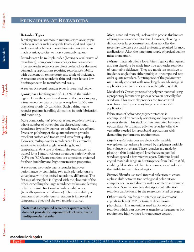
In figure 3-1, a plane polarized light wave incident on abirefringent material is vectorially decomposed into twoorthogonal components vibrating along the fast and slowaxes. Plane polarized light is oriented at 45° relative tothe fast axis of the retarder. The orthogonal polarizationcomponents travel through the material with differentvelocities (due to birefringence) and are phase shiftedrelative to each other producing a modified polarization
state. The transmitted light leaves the retarder ellipticallypolarized.
Retardance (in waves) is given by:
� = �t��
where:
� = birefringence (ne - no)� = wavelength of incident light (in nanometers)t = thickness of birefringent element
(in nanometers)
Retardance can also be expressed in units of length, thedistance that one polarization component is delayedrelative to the other. Retardance is then represented by:
�� = �� = �t
where �� is the retardance (in nanometers).
The above equations illustrate that retardance is stronglydependent upon both incident wavelength and retarderthickness.
All retarders suffer small retardance oscillations as afunction of wavelength when a coherent light source isused. This etalon effect can be substantial, depending uponthe physical characteristics of the retarder. Please seereferences 1, 5, and 6 listed on page 3 for more information.
fastaxis
fastaxis
Input polarization
Output polarization
Phase shift through retarder
45˚
Fig. 3-1 The effect of a retarder of arbitrary phase on a plane-polarized input beam
Page 20
PRINCIPLES OF RETARDERS
Retarders
Custom
Polarizers
Liqu
idC
rystalsSpatial L
ight
Modu
latorsM
ounts
Polarim
eters
Tel (303) 833 -4333 • Fax (303) 833 -4335 • e -ma i l : s a l e s@meadowla rk . com
Retarder TypesBirefringence is common in materials with anisotropicmolecular order such as crystals (both solid and liquid)and oriented polymers. Crystalline retarders are oftenmade of mica, calcite, or most commonly, quartz.
Retarders can be multiple-order (having several waves ofretardance), compound zero-order, or true zero-order.True zero-order retarders are often preferred for the mostdemanding applications requiring retardance stabilitywith wavelength, temperature, and angle of incidence. A true zero-order retarder is thin and must have a lowbirefringence to be manufactured easily.
A review of several retarder types is presented below.
Quartz has a birefringence of ~0.0092 in the visibleregion. From the equations shown on the previous page,a true zero-order quartz quarter waveplate for 550 nmoperation is only 15 �m thick. Such a thin, fragileretarder presents handling difficulties in both fabricationand mounting.
More commonly, multiple-order quartz retarders having awhole number of waves plus the desired fractionalretardance (typically quarter- or half-wave) are offered.Precision polishing of the quartz substrate providesexcellent surface and transmitted wavefront quality.However, multiple-order retarders can be extremelysensitive to incident angle, wavelength, andtemperature. As a rule of thumb, the retardance (inwaves) for a 1 mm thick quartz retarder varies by about -0.3% per °C. Quartz retarders are sometimes preferredfor their durability and high transmission properties.
A compound zero-order quartz retarder improvesperformance by combining two multiple-order quartzwaveplates with the desired retardance difference. Thefast axis of one plate is aligned with the slow axis of theother, cancelling the large retardance values and leavingonly the desired fractional retardance difference(typically quarter- or half-wave). Thermal stability ofcompound zero-order quartz retarders is improved astemperature effects of the two retarders cancel.
Mica, a natural mineral, is cleaved to precise thicknessesoffering true zero-order retarders. However, cleaving isdifficult over large apertures and does not offer thenecessary tolerance or spatial uniformity required for mostapplications. Also, the long term supply of optical qualitymica is uncertain.
Polymer materials offer a lower birefringence than quartzand can therefore be made into true zero-order retardersof reasonable thickness. They are much less sensitive toincidence angle than either multiple- or compound zero-order quartz retarders. Birefringence of the polymer weuse is nearly constant with wavelength, an advantage inapplications where the source wavelength may shift.
Meadowlark Optics protects the polymer material usinga proprietary lamination process between optically flatwindows. This assembly provides the transmittedwavefront quality necessary for precision opticalapplications.
Fabrication of achromatic polymer retarders isaccomplished by precisely orienting and layering severalpolymer sheets. This stack is then laminated betweenoptical flats. Achromatic polymer retarders offer theversatility needed for broadband applications withdemanding performance requirements.
Liquid crystal retarders are electrically variablewaveplates. Retardance is altered by applying a variable,low voltage waveform. These retarders are made byplacing a thin liquid crystal layer between parallelwindows spaced a few microns apart. Different liquidcrystal materials range in birefringence from 0.07 to 0.26,enabling fabrication of thin, true zero-order retarders inthe visible to near infrared region.
Fresnel Rhombs use total internal reflection to create a phase shift between two orthogonal polarizationcomponents. Fresnel rhombs make excellent achromaticretarders. A more complete description of reflectionretarders can be found in the references listed on page 3.
Other tunable birefringent retarders use electro-opticcrystals such as KD*P (potassium dideuteriumphosphate). This material is used in Pockels cellretarders which can operate at megahertz frequencies butrequire very high voltage for retardance control.
PRINCIPLES OF RETARDERS
Page 21
Note that a compound zero-order quartz retarderdoes not provide for improved field of view over amultiple-order retarder.
Ret
arde
rsC
ust
omP
olar
izer
sSpa
tial
Lig
ht
Mod
ula
tors
Liq
uid
Cry
stal
sM
ounts
Pol
arim
eter
s
Tel (303) 833 -4333 • Fax (303) 833 -4335 • web s i t e : www.meadowla rk . com
Naturally-occurring crystalline materials (calcite, mica, andquartz) have traditionally been the birefringent materials
of choice for retarders. Today’s applications require performanceversatility beyond the limitations of those crystals.
Meadowlark Optics specializes in the use of birefringentpolymers and liquid crystals for polarization control in precisionoptical applications. These innovative materials offer a uniquecombination of high performance and cost-effectiveness.
Birefringent PolymersOur polymer retarder assembly consists of birefringent polymermaterial laminated between two precision polished, opticallyflat BK-7 windows. Antireflection coatings and indexmatching optical cement help to maximize transmission in thevisible to near infrared region. This construction (shown infigure 3-2) ensures excellent transmitted wavefront quality,while minimizing beam deviation and surface reflection losses.
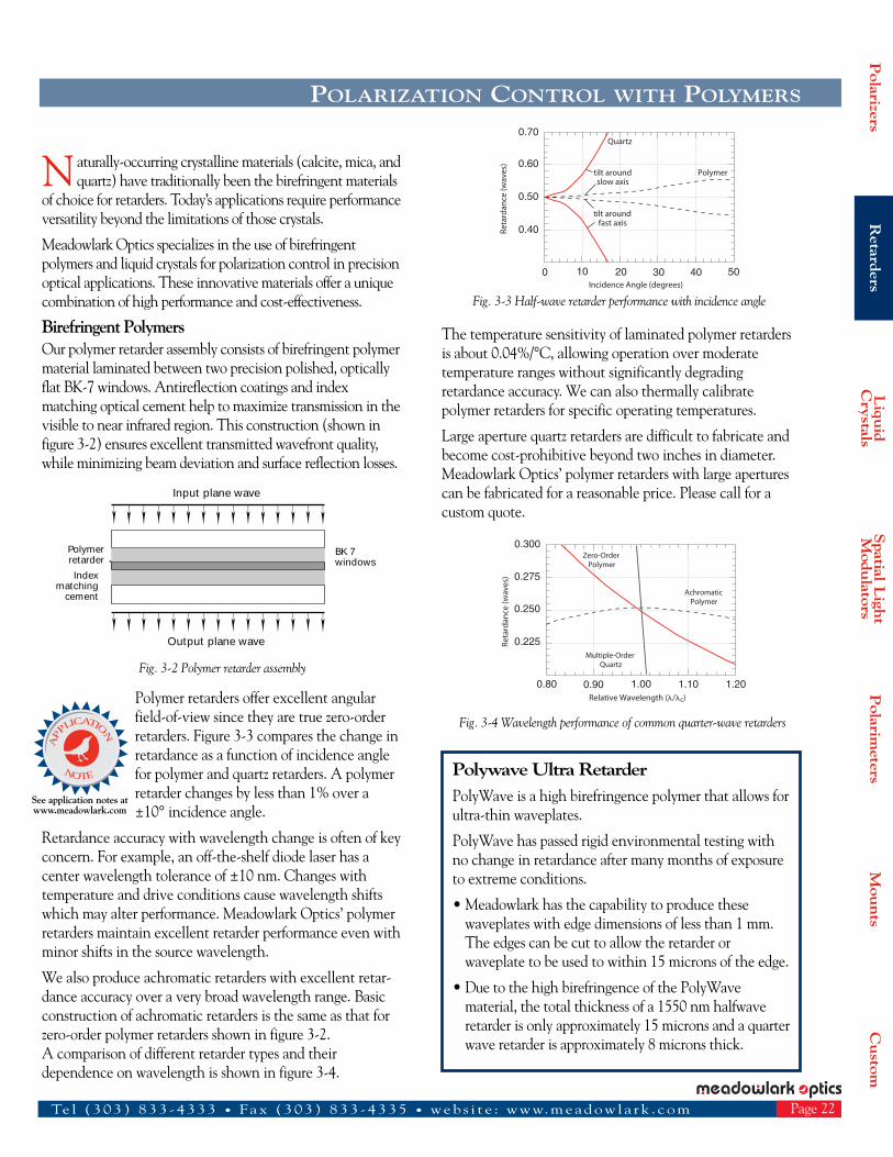
Polymer retarders offer excellent angularfield-of-view since they are true zero-orderretarders. Figure 3-3 compares the change inretardance as a function of incidence anglefor polymer and quartz retarders. A polymerretarder changes by less than 1% over a±10° incidence angle.
Retardance accuracy with wavelength change is often of keyconcern. For example, an off-the-shelf diode laser has acenter wavelength tolerance of ±10 nm. Changes withtemperature and drive conditions cause wavelength shiftswhich may alter performance. Meadowlark Optics’ polymerretarders maintain excellent retarder performance even withminor shifts in the source wavelength.
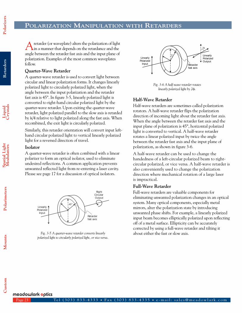
We also produce achromatic retarders with excellent retar-dance accuracy over a very broad wavelength range. Basicconstruction of achromatic retarders is the same as that forzero-order polymer retarders shown in figure 3-2. A comparison of different retarder types and theirdependence on wavelength is shown in figure 3-4.
The temperature sensitivity of laminated polymer retardersis about 0.04%/°C, allowing operation over moderatetemperature ranges without significantly degradingretardance accuracy. We can also thermally calibratepolymer retarders for specific operating temperatures.
Large aperture quartz retarders are difficult to fabricate andbecome cost-prohibitive beyond two inches in diameter.Meadowlark Optics’ polymer retarders with large aperturescan be fabricated for a reasonable price. Please call for acustom quote.
➛ ➛ ➛ ➛ ➛ ➛ ➛ ➛ ➛ ➛ ➛ ➛ ➛ ➛➛
Input plane wave
Output plane wave
BK 7windows
Polymerretarder
Indexmatching
cement
➛ ➛ ➛ ➛ ➛ ➛ ➛ ➛ ➛ ➛ ➛ ➛ ➛ ➛➛
10 20 30 40 500
0.50
0.40
0.60
0.70
Incidence Angle (degrees)
Quartz
Polymertilt aroundslow axis
tilt aroundfast axis
Reta
rdan
ce (w
aves
)
Fig. 3-3 Half-wave retarder performance with incidence angle
0.90 1.00 1.10 1.200.80
0.250
0.225
0.275
0.300
Relative Wavelength (�/�c)
Multiple-OrderQuartz
Zero-OrderPolymer
AchromaticPolymer
Reta
rdan
ce (w
aves
)
Fig. 3-4 Wavelength performance of common quarter-wave retarders
POLARIZATION CONTROL WITH POLYMERS
Page 22
NOTE
AP
PLICATIO
N
Retarders
Custom
Polarizers
Liqu
idC
rystalsSpatial L
ight
Modu
latorsM
ounts
Polarim
eters
Fig. 3-2 Polymer retarder assembly
Polywave Ultra Retarder
PolyWave is a high birefringence polymer that allows forultra-thin waveplates.
PolyWave has passed rigid environmental testing withno change in retardance after many months of exposureto extreme conditions.
• Meadowlark has the capability to produce thesewaveplates with edge dimensions of less than 1 mm.The edges can be cut to allow the retarder orwaveplate to be used to within 15 microns of the edge.
• Due to the high birefringence of the PolyWavematerial, the total thickness of a 1550 nm halfwaveretarder is only approximately 15 microns and a quarterwave retarder is approximately 8 microns thick.
See application notes atwww.meadowlark.com
Tel (303) 833 -4333 • Fax (303) 833 -4335 • e -ma i l : s a l e s@meadowla rk . com
Aretarder (or waveplate) alters the polarization of lightin a manner that depends on the retardance and the
angle between the retarder fast axis and the input plane ofpolarization. Examples of the most common waveplatesfollow.
Quarter-Wave RetarderA quarter-wave retarder is used to convert light betweencircular and linear polarization forms. It changes linearlypolarized light to circularly polarized light, when theangle between the input polarization and the retarder fast axis is 45°. In figure 3-5, linearly polarized light isconverted to right-hand circular polarized light by thequarter-wave retarder. Upon exiting the quarter-waveretarder, light polarized parallel to the slow axis is retardedby �/4 relative to light polarized along the fast axis. Whenrecombined, the exit light is circularly polarized.
Similarly, this retarder orientation will convert input left-hand circular polarized light to vertical linearly polarizedlight for a reversed direction of travel.
IsolatorA quarter-wave retarder is often combined with a linearpolarizer to form an optical isolator, used to eliminateundesired reflections. A common application preventsunwanted reflected light from re-entering a laser cavity.Please see page 17 for a discussion of optical isolators.
Half-Wave RetarderHalf-wave retarders are sometimes called polarizationrotators. A half-wave retarder flips the polarizationdirection of incoming light about the retarder fast axis.When the angle between the retarder fast axis and theinput plane of polarization is 45°, horizontal polarizedlight is converted to vertical. A half-wave retarderrotates a linear polarized input by twice the anglebetween the retarder fast axis and the input plane ofpolarization, as shown in figure 3-6.
A half-wave retarder can be used to change the handedness of a left-circular polarized beam to right-circular polarized, or vice versa. A half-wave retarder isalso conveniently used to change the polarizationdirection where mechanical rotation of a large laser is impractical.
Full-Wave RetarderFull-wave retarders are valuable components foreliminating unwanted polarization changes in an opticalsystem. Many optical components, especially metalmirrors, alter the polarization state by introducingunwanted phase shifts. For example, a linearly polarizedinput beam becomes elliptically polarized upon reflectingoff of a metal surface. Ellipticity can be accuratelycorrected by using a full-wave retarder and tilting itabout either the fast or slow axis.
45°
Retarderfast axis
LinearlyPolarized
Input
RightCircular Output
Fig. 3-5 A quarter-wave retarder converts linearly polarized light to circularly polarized light, or vice versa.
�
2�
Retarderfast axis
LinearlyPolarized
Input
LinearlyPolarizedOutput
Fig. 3-6 A half-wave retarder rotates linearly polarized light by 2�.
POLARIZATION MANIPULATION WITH RETARDERS
Page 23
Ret
arde
rsC
ust
omP
olar
izer
sSpa
tial
Lig
ht
Mod
ula
tors
Liq
uid
Cry
stal
sM
ounts
Pol
arim
eter
s
Tel (303) 833 -4333 • Fax (303) 833 -4335 • web s i t e : www.meadowla rk . com
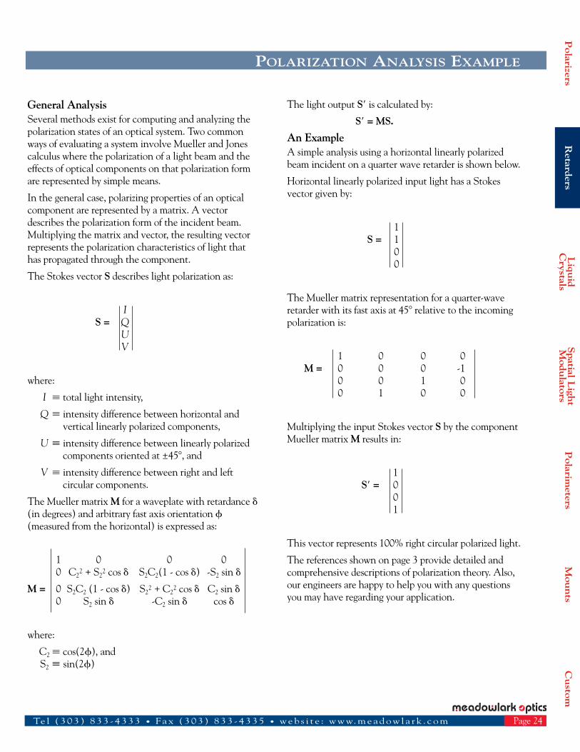
General AnalysisSeveral methods exist for computing and analyzing thepolarization states of an optical system. Two commonways of evaluating a system involve Mueller and Jonescalculus where the polarization of a light beam and theeffects of optical components on that polarization formare represented by simple means.
In the general case, polarizing properties of an opticalcomponent are represented by a matrix. A vectordescribes the polarization form of the incident beam.Multiplying the matrix and vector, the resulting vectorrepresents the polarization characteristics of light thathas propagated through the component.
The Stokes vector S describes light polarization as:
IS = Q
UV
where:
I total light intensity,
Q intensity difference between horizontal and vertical linearly polarized components,
U intensity difference between linearly polarizedcomponents oriented at ±45, and
V intensity difference between right and left circular components.
The Mueller matrix M for a waveplate with retardance �(in degrees) and arbitrary fast axis orientation �(measured from the horizontal) is expressed as:
1 0 0 00 C2
2 + S22 cos � S2C2(1 - cos �) -S2 sin �
M = 0 S2C2 (1 - cos �) S22 + C2
2 cos � C2 sin �0 S2 sin � -C2 sin � cos �
where:
C2 cos(2�), and S2 sin(2�)
The light output S� is calculated by:
S� = MS.
An ExampleA simple analysis using a horizontal linearly polarizedbeam incident on a quarter wave retarder is shown below.
Horizontal linearly polarized input light has a Stokesvector given by:
1S = 1
00
The Mueller matrix representation for a quarter-waveretarder with its fast axis at 45 relative to the incomingpolarization is:
1 0 0 0M = 0 0 0 -1
0 0 1 00 1 0 0
Multiplying the input Stokes vector S by the componentMueller matrix M results in:
1S� = 0
01
This vector represents 100% right circular polarized light.
The references shown on page 3 provide detailed andcomprehensive descriptions of polarization theory. Also,our engineers are happy to help you with any questionsyou may have regarding your application.
POLARIZATION ANALYSIS EXAMPLE
Page 24
Retarders
Custom
Polarizers
Liqu
idC
rystalsSpatial L
ight
Modu
latorsM
ounts
Polarim
eters
Tel (303) 833 -4333 • Fax (303) 833 -4335 • e -ma i l : s a l e s@meadowla rk . com
stock wavelengths custom regions
500 1000 1500
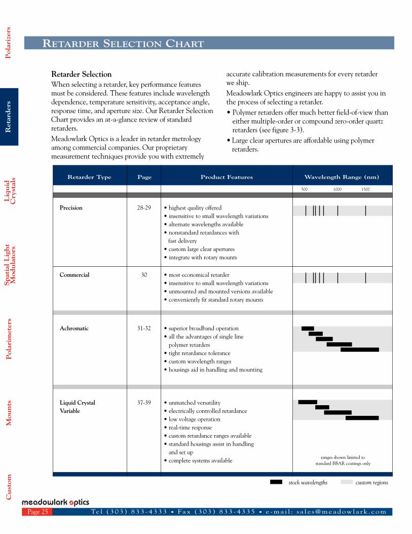
Retarder Type Page Product Features Wavelength Range (nm)
Precision 28-29 • highest quality offered• insensitive to small wavelength variations• alternate wavelengths available• nonstandard retardances with
fast delivery • custom large clear apertures• integrate with rotary mounts
Commercial 30 • most economical retarder• insensitive to small wavelength variations• unmounted and mounted versions available• conveniently fit standard rotary mounts
Achromatic 31-32 • superior broadband operation• all the advantages of single line
polymer retarders• tight retardance tolerance• custom wavelength ranges• housings aid in handling and mounting
Liquid Crystal 37-39 • unmatched versatilityVariable • electrically controlled retardance
• low voltage operation• real-time response• custom retardance ranges available• standard housings assist in handling
and set up• complete systems available
Retarder SelectionWhen selecting a retarder, key performance featuresmust be considered. These features include wavelengthdependence, temperature sensitivity, acceptance angle,response time, and aperture size. Our Retarder SelectionChart provides an at-a-glance review of standardretarders.Meadowlark Optics is a leader in retarder metrologyamong commercial companies. Our proprietary measurement techniques provide you with extremely
accurate calibration measurements for every retarder we ship. Meadowlark Optics engineers are happy to assist you inthe process of selecting a retarder. • Polymer retarders offer much better field-of-view than
either multiple-order or compound zero-order quartzretarders (see figure 3-3).
• Large clear apertures are affordable using polymerretarders.
RETARDER SELECTION CHART
Page 25
Ret
arde
rsC
ust
omP
olar
izer
sSpa
tial
Lig
ht
Mod
ula
tors
Liq
uid
Cry
stal
sM
ounts
Pol
arim
eter
s
ranges shown limited tostandard BBAR coatings only
Tel (303) 833 -4333 • Fax (303) 833 -4335 • web s i t e : www.meadowla rk . com
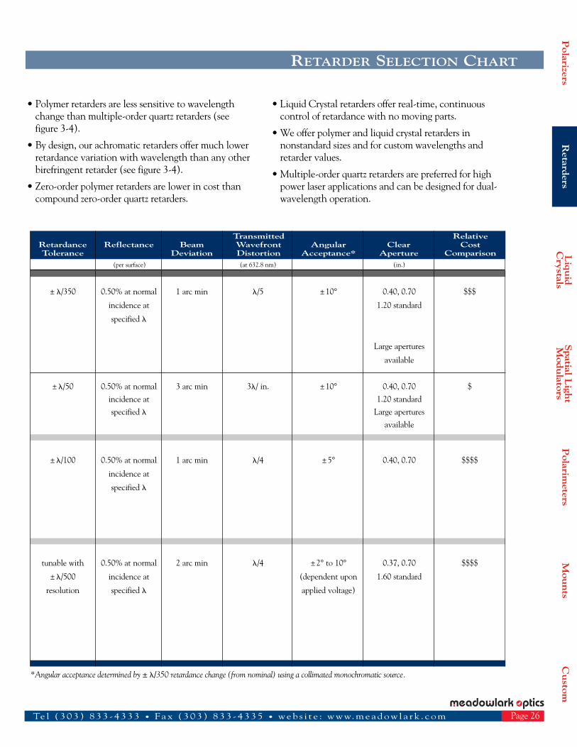
*Angular acceptance determined by ± �/350 retardance change (from nominal) using a collimated monochromatic source.
Transmitted RelativeRetardance Reflectance Beam Wavefront Angular Clear CostTolerance Deviation Distortion Acceptance* Aperture Comparison
(per surface) (at 632.8 nm) (in.)
± �/350 0.50% at normal 1 arc min �/5 ±10° 0.40, 0.70 $$$
incidence at 1.20 standard
specified �
Large apertures
available
± �/50 0.50% at normal 3 arc min 3�/ in. ±10° 0.40, 0.70 $
incidence at 1.20 standard
specified � Large apertures
available
± �/100 0.50% at normal 1 arc min �/4 ±5° 0.40, 0.70 $$$$
incidence at
specified �
tunable with 0.50% at normal 2 arc min �/4 ±2° to 10° 0.37, 0.70 $$$$
± �/500 incidence at (dependent upon 1.60 standard
resolution specified � applied voltage)
• Polymer retarders are less sensitive to wavelengthchange than multiple-order quartz retarders (see figure 3-4).
• By design, our achromatic retarders offer much lowerretardance variation with wavelength than any otherbirefringent retarder (see figure 3-4).
• Zero-order polymer retarders are lower in cost thancompound zero-order quartz retarders.
• Liquid Crystal retarders offer real-time, continuouscontrol of retardance with no moving parts.
• We offer polymer and liquid crystal retarders innonstandard sizes and for custom wavelengths andretarder values.
• Multiple-order quartz retarders are preferred for highpower laser applications and can be designed for dual-wavelength operation.
RETARDER SELECTION CHART
Page 26
Retarders
Custom
Polarizers
Liqu
idC
rystalsSpatial L
ight
Modu
latorsM
ounts
Polarim
eters
Tel (303) 833 -4333 • Fax (303) 833 -4335 • e -ma i l : s a l e s@meadowla rk . com
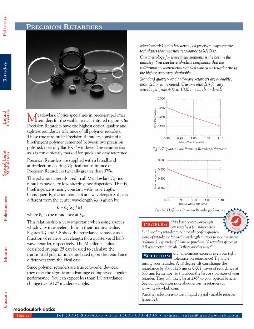
Meadowlark Optics specializes in precision polymerretarders for the visible to near infrared region. Our
Precision Retarders have the highest optical quality andtightest retardance tolerance of all polymer retarders.These true zero-order Precision Retarders consist of abirefringent polymer cemented between two precisionpolished, optically flat BK-7 windows. The retarder fastaxis is conveniently marked for quick and easy reference.
Precision Retarders are supplied with a broadbandantireflection coating. Optical transmittance of aPrecision Retarder is typically greater than 97%.
The polymer materials used in all Meadowlark Opticsretarders have very low birefringence dispersion. That is,birefringence is nearly constant with wavelength.Consequently, the retardance � at a wavelength � that isdifferent from the center wavelength �c is given by:
� = �c(�c / �)
where �c is the retardance at �c.
This relationship is very important when using sourceswhich vary in wavelength from their nominal value. Figures 3-7 and 3-8 show the retardance behavior as afunction of relative wavelength for a quarter- and half-wave retarder, respectively. The Mueller calculusdescribed on page 25 can be used to calculate thetransmitted polarization state based upon the retardancedifferences from the ideal case.
Since polymer retarders are true zero-order devices, they offer the significant advantage of improved angularperformance. You can expect less than 1% retardancechange over ±10° incidence angle.
Meadowlark Optics has developed precision ellipsometrictechniques that measure retardance to �/1000. Our metrology for these measurements is the best in theindustry. You can have absolute confidence that thecalibration measurements supplied with your retarder are ofthe highest accuracy obtainable.Standard quarter- and half-wave retarders are available,mounted or unmounted. Custom retarders for anywavelength from 400 to 1800 nm can be ordered.
0.95 1.00 1.05 1.100.90
0.250
0.225
0.275
0.300
Relative Wavelength (�/�c)
Reta
rdan
ce (w
aves
)
Fig. 3-7 Quarter-wave Premium Retarder performance
0.95 1.00 1.05 1.100.90
0.500
0.450
0.550
0.600
Relative Wavelength (�/�c)
Reta
rdan
ce (w
aves
)
Fig. 3-8 Half-wave Premium Retarder performance
PRECISION RETARDERS
Page 27
“My laser center wavelength can vary by a few nanometers,
but I need my retarder to be a nearly perfect quarter-wave of retardance for each wavelength in order to give maximumisolation. I’ll go broke if I have to purchase 10 retarders spaced at0.5 nanometer intervals. Is there another way?”
0.5 nanometers exceeds even our tighttolerance on retardance! Try angle
tuning your retarder. A 10 degree tilt can change theretardance by about l.25 nm or 0.002 waves of retardance at633 nm. Remember to tilt about the fast or slow axes of yourretarder. They will likely be at ±45° to your optical bench.See our application note about errors in retarders atwww.meadowlark.com. Another solution is to use a liquid crystal variable retarder(page 37).
PROBLEM
SOLUTION
NOTE A
P
PLICATIO
N
Ret
arde
rsC
ust
omP
olar
izer
sSpa
tial
Lig
ht
Mod
ula
tors
Liq
uid
Cry
stal
sM
ounts
Pol
arim
eter
s
Tel (303) 833 -4333 • Fax (303) 833 -4335 • web s i t e : www.meadowla rk . com
Our Precision Retarders have the highest optical quality andtightest retardance tolerance of all our polymer retarders.
Please contact our sales department to obtain a price listfor our standard components.
Custom size retarders with improved transmittedwavefront distortion and/or beam deviation areavailable. Your requirements for custom shapes and sizesare also welcome. Please call for a quote.
Meadowlark Optics’ one and two inch diameterretarders conveniently fit our Rotary Mounts. Please refer to the Mounts section of our catalog for more information.
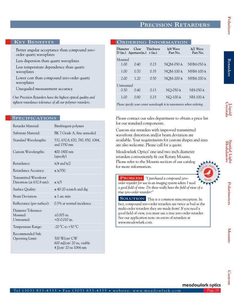
■ Better angular acceptance than compound zero-order quartz waveplates
■ Less dispersion than quartz waveplates■ Less temperature dependence than quartz
waveplates■ Lower cost than compound zero-order quartz
waveplates■ Unequaled measurement accuracy
Retarder Material: Birefringent polymer
Substrate Material: BK 7 Grade A, fine annealed
Standard Wavelengths: 532, 632.8, 670, 780, 850, 1064, and 1550 nm
Custom Wavelengths: 400-1800 nm (specify)
Retardance: �/4 and �/2
Retardance Accuracy: ≤ �/350
Transmitted Wavefront Distortion (at 632.8 nm): ≤ �/5
Surface Quality: ≤ 40-20 scratch and dig
Beam Deviation: ≤ 1 arc min
Reflectance (per surface): 0.5% at normal incidence
Diameter Tolerance:Mounted: ±0.005 in.Unmounted: +0/-0.010 in.
Temperature Range: -20 C to +50 C
Recommended Safe Operating Limit: 500 W/cm2 CW
600 mJ/cm2 20 ns, visible4 J/cm2 20 ns 1064 nm
Diameter Clear Thickness ��/4 Wave ��/2 WaveD (in.) Aperture(in.) t (in.) Part No. Part No.
Mounted1.00 0.40 0.23 NQM-050-� NHM-050-�
1.00 0.70 0.35 NQM-100-� NHM-100-�
2.00 1.20 0.50 NQM-200-� NHM-200-�
Unmounted0.50 0.40 0.13 NQ-050-� NH-050-�
1.00 0.80 0.25 NQ-100-� NH-100-�
Please specify your center wavelength � in nanometers when ordering.
PRECISION RETARDERS
Page 28
“I purchased a compound zero-order retarder for use in an imaging system where I need a good field of view. Do these really have the field of view of atrue zero-order retarder?”
This is a common misconception. Infact, compound zero-order retarders are twice as bad as themulti-order retarders they are made from! If you need agood field of view, you must use a true zero-order retarder.See our application note on errors of retarders atwww.meadowlark.com.
PROBLEM
SOLUTION
Retarders
Custom
Polarizers
Liqu
idC
rystalsSpatial L
ight
Modu
latorsM
ounts
Polarim
eters
NOTE
AP
PLICATIO
N
ORDERING INFORMATIONKEY BENEFITS
SPECIFICATIONS
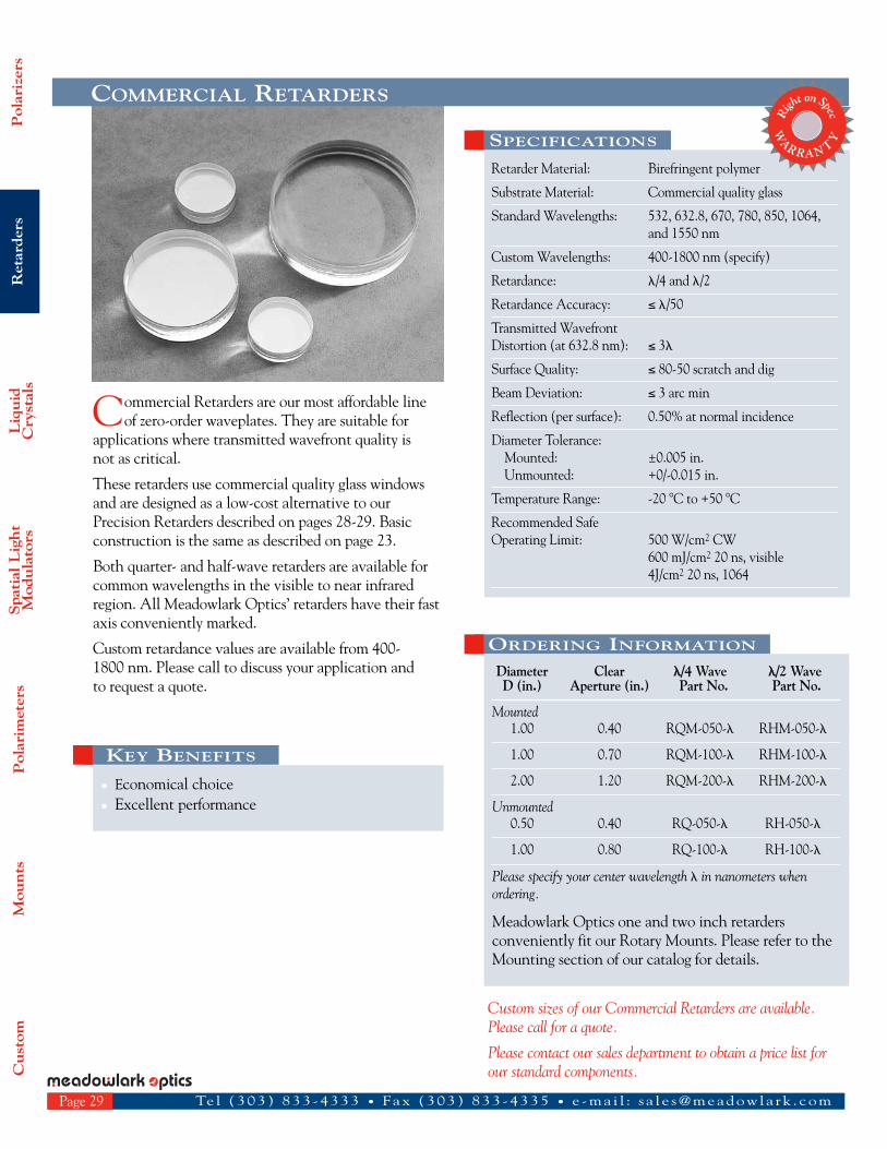
Commercial Retarders are our most affordable line of zero-order waveplates. They are suitable for
applications where transmitted wavefront quality is not as critical.
These retarders use commercial quality glass windowsand are designed as a low-cost alternative to ourPrecision Retarders described on pages 28-29. Basicconstruction is the same as described on page 23.
Both quarter- and half-wave retarders are available forcommon wavelengths in the visible to near infraredregion. All Meadowlark Optics’ retarders have their fastaxis conveniently marked.
Custom retardance values are available from 400-1800 nm. Please call to discuss your application and to request a quote.
Te l (303) 833 -4333 • Fax (303) 833 -4335 • e -ma i l : s a l e s@meadowla rk . com
Retarder Material: Birefringent polymer
Substrate Material: Commercial quality glass
Standard Wavelengths: 532, 632.8, 670, 780, 850, 1064, and 1550 nm
Custom Wavelengths: 400-1800 nm (specify)
Retardance: �/4 and �/2
Retardance Accuracy: ≤ �/50
Transmitted Wavefront Distortion (at 632.8 nm): ≤ 3�
Surface Quality: ≤ 80-50 scratch and dig
Beam Deviation: ≤ 3 arc min
Reflection (per surface): 0.50% at normal incidence
Diameter Tolerance:Mounted: ±0.005 in.Unmounted: +0/-0.015 in.
Temperature Range: -20 C to +50 C
Recommended Safe Operating Limit: 500 W/cm2 CW
600 mJ/cm2 20 ns, visible4J/cm2 20 ns, 1064
Diameter Clear ��/4 Wave ��/2 WaveD (in.) Aperture (in.) Part No. Part No.
Mounted1.00 0.40 RQM-050-� RHM-050-�
1.00 0.70 RQM-100-� RHM-100-�
2.00 1.20 RQM-200-� RHM-200-�
Unmounted0.50 0.40 RQ-050-� RH-050-�
1.00 0.80 RQ-100-� RH-100-�
Please specify your center wavelength � in nanometers whenordering.
Meadowlark Optics one and two inch retardersconveniently fit our Rotary Mounts. Please refer to theMounting section of our catalog for details.
Custom sizes of our Commercial Retarders are available.Please call for a quote.
Please contact our sales department to obtain a price list forour standard components.
COMMERCIAL RETARDERS
Page 29
■ Economical choice■ Excellent performance
Ret
arde
rsC
ust
omP
olar
izer
sSpa
tial
Lig
ht
Mod
ula
tors
Liq
uid
Cry
stal
sM
ounts
Pol
arim
eter
s
ORDERING INFORMATION
KEY BENEFITS
SPECIFICATIONS
Tel (303) 833 -4333 • Fax (303) 833 -4335 • web s i t e : www.meadowla rk . com Page 30
Retarders
Custom
Polarizers
Liqu
idC
rystalsSpatial L
ight
Modu
latorsM
ounts
Polarim
eters
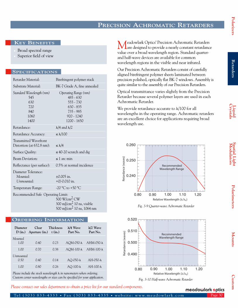
Meadowlark Optics’ Precision Achromatic Retardersare designed to provide a nearly constant retardance
value over a broad wavelength region. Standard quarter-and half-wave devices are available for commonwavelength regions in the visible and near infrared.
Our Precision Achromatic Retarders consist of carefullyaligned birefringent polymer sheets laminated betweenprecision polished, optically flat BK-7 windows. Assembly isquite similar to the assembly of our Precision Retarders.
Optical transmittance varies slightly from the PrecisionRetarder because several polymer layers are used in eachAchromatic Retarder.
We provide retardance accurate to �/100 for allwavelengths in the operating range. Achromatic retardersare an excellent choice for applications requiring broadwavelength use.
0.90 1.00 1.10 1.200.80
0.250
0.240
0.260
Relative Wavelength (�/�c)
RecommendedWavelength Range
Reta
rdan
ce (w
aves
)
Fig. 3-9 Quarter-wave Achromatic Retarder
0.90 1.00 1.10 1.200.80
0.510
0.500
0.490
0.520
Relative Wavelength (�/�c)
RecommendedWavelength Range
Reta
rdan
ce (w
aves
)
Fig. 3-10 Half-wave Achromatic Retarder
PRECISION ACHROMATIC RETARDERS
Retarder Material: Birefringent polymer stack
Substrate Material: BK-7 Grade A, fine annealed
Standard Wavelength (nm) Operating Range (nm)545 485 - 630 630 555 - 730720 630 - 835840 735 - 9851060 920 - 12401400 1200 - 1650
Retardance: �/4 and �/2
Retardance Accuracy: ≤ �/100
Transmitted WavefrontDistortion (at 632.8 nm): ≤ �/4
Surface Quality: ≤ 40-20 scratch and dig
Beam Deviation: ≤ 1 arc min
Reflectance (per surface): 0.5% at normal incidence
Diameter Tolerance:Mounted: ±0.005 in.Unmounted: +0/-0.010 in.
Temperature Range: -20 °C to +50 °C
Recommended Safe Operating Limit:500 W/cm2 CW300 mJ/cm2 10 ns, visible500 mJ/cm2 10 ns, 1064 nm
Diameter Clear Thickness ��/4 Wave ��/2 WaveD (in.) Aperture (in.) t (in.) Part No. Part No.
Mounted1.00 0.40 0.23 AQM-050-� AHM-050-�
1.00 0.70 0.38 AQM-100-� AHM-100-�
Unmounted0.50 0.40 0.14 AQ-050-� AH-050-�
1.00 0.80 0.26 AQ-100-� AH-100-�
Please include the stock wavelength � in nanometers when ordering.Custom center wavelengths or sizes can be specified for your application.
■ Broad spectral range ■ Superior field of view
ORDERING INFORMATION
KEY BENEFITS
SPECIFICATIONS
Please contact our sales department to obtain a price list for our standard components.
Tel (303) 833 -4333 • Fax (303) 833 -4335 • e -ma i l : s a l e s@meadowla rk . com
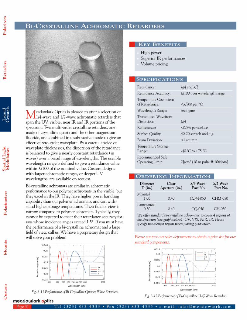
Meadowlark Optics is pleased to offer a selection of1/4-wave and 1/2-wave achromatic retarders that
span the UV, visible, near IR and IR portions of thespectrum. Two multi-order crystalline retarders, onemade of crystalline quartz and the other magnesiumfluoride, are combined in a subtractive mode to give aneffective zero-order waveplate. By a careful choice ofwaveplate thicknesses, the dispersion of the retardanceis balanced to give a nearly constant retardance (inwaves) over a broad range of wavelengths. The useablewavelength range is defined to give a retardance valuewithin �/100 of the nominal value. Custom designswith larger achromatic ranges, or deeper UVwavelengths, are available on request.
Bi-crystalline achromats are similar in achromaticperformance to our polymer achromats in the visible, butthey excel in the IR. They have higher power handlingcapability than our polymer achromats, and can with-stand higher storage temperatures. Their field of view isnarrow compared to polymer achromats. Typically, theycannot be expected to meet their retardance accuracy forrays whose incidence angles exceed 1.5°. If you must havethe performance of a bi-crystalline achromat and a largefield of view, call us. We have a proprietary design thatwill solve your problem!
Retardance: �/4 and �/2
Retardance Accuracy: �/100 over wavelength range
Temperature Coefficientof Retardance: <�/500 per °C
Wavelength Range: see figure
Transmitted Wavefront Distortion: �/4
Reflectance: <0.5% per surface
Surface Quality: 40-20 scratch and dig
Beam Deviation: <1 arc min
Temperature Storage Range: -40 C to +75 C
Recommended Safe Operating Limit: 2J/cm2 (10 ns pulse @ 1064nm)
Diameter Clear ��/4 Wave ��/2 WaveD (in.) Aperture (in.) Part No. Part No.
Mounted1.00 0.40 CQM-050 CHM-050
Unmounted0.50 0.40 CQ-050 CH-050
We offer standard bi-crystalline achromatic to cover 4 regions ofthe spectrum (see graph below): UV, VIS, NIR, IR. Please specify wavelength region when placing your order.
BI-CRYSTALLINE ACHROMATIC RETARDERS
Page 31
■ High power■ Superior IR performances■ Volume pricing
300
0.265
0.26
0.255
0.25
0.245
0.24
0.235400 900500 600 700 800 1000 2000
Wavelength (nm)
Reta
rdat
ion
(wav
es)
UVVISNIRIR
Fig. 3-11 Performance of Bi-Crystalline Quarter-Wave Retarders
Ret
arde
rsC
ust
omP
olar
izer
sSpa
tial
Lig
ht
Mod
ula
tors
Liq
uid
Cry
stal
sM
ounts
Pol
arim
eter
s
ORDERING INFORMATION
KEY BENEFITS
SPECIFICATIONS
Please contact our sales department to obtain a price list for ourstandard components.
0.515
0.51
0.505
0.5
0.495
0.49
0.485400 900500 600 700 800 1000 2000
Wavelength (nm)
Reta
rdat
ion
(wav
es)
UVVISNIRIR
Fig. 3-12 Performance of Bi-Crystalline Half-Wave Retarders