principles of pumpsirieen.indianrailways.gov.in/uploads/files/1302522604445-principles... · out...
TRANSCRIPT

PREFACE The book of “Principles of Pumps and Pumping Installation” was
brought out by Institution of Railway Electrical Engineers (IREE) long back.
Since, lot of changes have taken place in the field of Railway Electrical
Engineering, it has become necessary to incorporate the changes in this
volume. Few additions and modifications regarding pumps are also
included in this book.
For bringing out this book Shri Suryawanshi M.A., Raj Bhasha Supdtt.
And Shri Sanjay Swarup, Section Engineer have made substantial efforts,
under the guidance of Shri D. Ramaswamy, Senior Professor (Academics).
I am delighted to note that lot of efforts have been put-up in bringing
out this “Principles of Pumps and Pumping Installation” in the present form.
I am sure that this book will serve the needs of Electrical Engineers working
in the field of General Services.
Nasik Road A.K.RAWAL 15th April, 2010 DIRECTOR

PRINCIPLES OF PUMPS AND
PUMPING INSTALLATION
CONTENTS
Chapter No.
Topic
Page
01
Basic concepts of Pumping. 01
02
Types of pumps 12
03
Characteristics of Centrifugal Pumps. 33
04
System. head characteristics. 38
05
Design of water supply pumping installations – Basic considerations. 43
06
Selection of Centrifugal Pumps. 51
07
Pumping Stations and Machinery. 59
08
Installation, Operation and Maintenance of Pumps 86
09
Energy Conservation in Pumps 97

1. BASIC CONCEPTS OF PUMPING 1.0 INTRODUCTION
A pump is a device or an apparatus used for conveying a fluid from one point to other, usually through a pipe. A pump may, therefore, be defined as a mechanical device which translates the mechanical energy imparted to it from an external source (electric motor, diesel engine or even manual energy) into hydraulic energy in the fluid handled by it. As a consequence, the energy level of fluid handled by the pump or flowing through the pump is augmented, making it possible for the fluid to move from a lower level to a higher level, against gravity and friction.
There is a vast array of pumps for the innumerable types of jobs and duties to be handled in the complex industrial world. The electrical engineer in railways is called upon to specify, purchase, install, operate and satisfactorily maintain electrically driven and diesel driven centrifugal pumps dealing with colony, railway station, workshop and offices' water supply needs. In some railways, a few installations do exist, where sewage pumps have been installed and maintained in large railway colonies.
Indian Railways are spread over the vast sub-continent and traverse a diverse range of terrain and climate. Depending upon the terrain, such as the dry desert regions of Rajasthan, the perennially flowing river fed regions in the Gangetic belt or the rocky terrains of the Chambal and Deccan regions and, also depending upon the source of water, the yield of the source, distance and elevation over which the water is conveyed and therefore the head encountered would vary considerably. Accordingly the duty requirement of the pumps would vary. The pump to be used could be a horizontal spindle, a submersible pump or, an ejecto pump and so on.
There are also situations/locations, which are somewhat unique, such as an inspection-pit in a loco or EMU shed where the water to be pumped out is unclear and mixed with solid particles, grease, cotton waste etc, and has to be pumped out only against a small head. This would call for the use of a non-clog pump.
It is therefore necessary to have a detailed understanding of the nature and performance characteristics of these various types of pumps.
1.1 POSITIVE DISPLACEMENT PUMPS
In these types of pumps, the medium pumped together with any air which may have entered into the suction pipe gets positively displaced from the suction side to the delivery side at every revolution. Therefore, an important feature of these pumps is that these are inherently self-priming i.e. air in the suction pipe is effectively removed. Reciprocating and rotary pumps are the examples of these types of pumps.
A centrifugal pump on the other hand works only when the pump casing and the suction pipe are entirely filled with water and no air has entered in.
3

1.2 PRIMING
Priming means filling the pump and suction pipe completely with water so that all air is expelled from the system. Unless a centrifugal pump is solidly primed and water which has considerable weight is whirled at a high speed by the impellers, the necessary centrifugal force will not be created to rush the water against the static and friction head in the delivery pipe. Not only should the pump be fully primed when it is started, but it should remain fully primed throughout the period it is running.
Priming can be classified into two categories viz. (i) manual and (ii) mechanical. When the suction pipe is small i.e. where the diameter of suction pipe and length is also small, the suction pipe and pump casing is filled with water manually. When the diameter of suction pipe is large i.e. 200 mm or more and also long, mechanical priming is adopted, since the quantity of water required for filling such a suction pipe would be enormous. In mechanical priming, air from the suction system is emptied out by connecting a motor driven exhaust pump or air ejector. This type of pump is also called 'self ejecting pump. This is, however, different from ejector (jet) pump.
1.3 SYSTEM HEAD
The liquid possessing head provided by the pump encounters different resistances while flowing from the source to the point of discharge. The head for such resistance is called 'system head'. System head consists of the following components; • Total static head, • Frictional Head, • Velocity Head.
The total head developed is a measure of the energy imparted to the water, to move it from the source to the overhead storage tank. The net energy gain experienced by the liquid or water from the moment it begins to move from the source to the moment it finally comes to rest in the overhead tank is equivalent to the dead head or static head. However, the effective energy increment that has to be imparted by the pump must be the sum of the static head and all the energy losses. The details of these are discussed in the following paragraphs. 1.3.1 Total static head (Hs) This comprises of two components viz., (i) Static suction head. (ii) Static delivery or discharge head. The sum of the two components represents the total static head and is not affected by the length of the pipe line, size of the pipe line and, existence of the bends in the pipe line
Static suction head (Hss)
This represents the difference in level between the centre line of the pump (also called datum or datum line and used as reference level in all pumping calculations) and the water level in the source. It indicates the vertical height near which the water has to be lifted or sucked on
4

the suction side of the pump. When the source is below the pump the static suction lift (as it is called) has to be added to all other heads to workout the total head on the pump. If, however, the source is above the pump, the natural gravitational flow available acts as a positive head (as it is called) and reduces the duty on the pump. The suction head is then subtracted from all other heads to work out the total head.
Static Discharge Head (Hsd)
This represents the height through which the delivered water has to be lifted on the discharge side of the pump. It indicates the difference in level or height between the datum and the delivery spout of the discharge pipe if water discharges into an overhead service tank or the level of water in that tank at a given instant, if the delivery pipe is connected to the bottom of the tank. 1.3.2 Friction Head (Hf)
Water flowing through the suction and delivery pipes and the various fittings like bends, valves etc. encounters friction or resistance to its flow. The frictional resistance to the water flow through a pipe depends on the velocity of flow, quality of flow (presence or absence of solid matter), quality of surface of the pipe etc. The calculation of frictional head (or more appropriately loss of head on account of friction) can be done by the use of different formulae developed by (i) Darcy - Weisbach (ii) Manning (iii) Hazen Williams etc. However, precomputed tables and graphs using these formulae are available from pipe manufacturers. The Hydraulic Institute of America's piping hand-book gives tables and graphs which are ready capsules for various sizes of pipes, material composition of pipes, volume rate of flow etc. per metre length or 100 m length of pipe line. The total friction head in metres of water for the entire length of piping of any pumping installation can readily be computed from the values so obtained from the tables or graphs.
The frictional resistance to flow on account of fittings such as bends, elbows, valves etc. is greater than that attributable to the actual length of each such component. Therefore, an equivalent of straight pipe line having frictional resistance to that of the fittings is determined for each type and size of fittings and indicated in the source material referred to above. The sum of equivalent length of pipeline of all such fittings is added to the actual length of pipeline to calculate the friction head for the total installation or system. 1.3.3 Velocity Head (Hv)
The velocity head of water flowing in a given pipe at a given velocity is equivalent to the static head through which it would have to fall in order to attain the given velocity.
Velocity Head (Hv) = V2/2g where,
Hv = Velocity head in metres of water,
V = Velocity of flow in the pipe in M/sec.
g = Acceleration due to gravity in M/sec2. 1.4 LIMITATIONS OF SUCTION LIFT
The maximum permissible suction lift of the rotodynamic pump is limited by the following factors : 1.4.1 Pressure on exposed surface of the liquid in the source
5

It is one of the factors which limit the maximum permissible suction lift. Higher pressure means higher permissible suction lift. The atmospheric pressure at sea level is nearly 1 Kg/Cm2 as such theoretical maximum suction lift is 10 Mts. of water. Atmospheric pressure varies from place to place according to the altitude -of the place Suction lift at a place of higher altitude will be comparatively less than the suction lift at a place of lower altitude. The suction lift is reduced approximately by 1.2 M for each 1000 Mts increase in altitude above sea level.
1.4.2 Frictional head of the suction pipe The frictional head further reduces the maximum permissible suction lift. As the frictional head depends upon the length of suction pipe, diameter of suction pipe, roughness of internal surface of pipe and rate of flow, the suction lift is limited by these factors in the manner they affect the frictional head. Because of these reasons, longer length and lesser diameter pipe is not recommended for use in suction side. Also the suction lift of higher discharge pump is lower than the suction lift of lower discharge pump.
1.4.3 Effect of secondary heads on suction lift
The secondary heads on suction side depends upon various fittings used such as foot-valve, bends etc. and their number. The head due to resistances in these various fittings on suction side further reduces the suction lift. For this reason, use of more bends, tees, elbows etc. is not recommended in suction side.
1.4.4 Vapour pressure of the liquid Absolute pressure at the impeller eye is very low and there is every chance that at such pressure, the liquid may form vapour even at ordinary working temperatures of the liquid. Rate of evaporation increases with increase in temperature. Rate of vapour formation at a particular temperature and absolute pressure also varies according to the type of liquid. The rate of evaporation is more in case of petrol which is more volatile than water. Vapour so formed has considerable pressure and reduces suction lift. 1.4.5 Internal head drop in the pump It is the drop in the head of the liquid between the suction flange and the point within the pump at which the absolute pressure is minimum. This internal head drop in the rotodynamic pump is called 'The dynamic depression head'.
From the above it is seen that the maximum permissible suction lift of a pump is equal to the head due to pressure on exposed surface of the liquid in the source minus internal head drop, frictional head, secondary heads, vapour pressure of liquid and velocity in the suction system. 1.5 NET POSITIVE SUCTION HEAD (NPSH)
It is more often than not that a centrifugal pump is installed at a level higher than the source of water. The pump by itself has not the power to initiate the flow of liquid, so long as the pump remains dry. When the impeller of the pump has only air to work upon, the differential pressure generated is negligible in relation to the designed working pressure of the pump, No
6

matter for how long the pump were to run, the water would never rise more than 30 to 50 mm up the suction pipe.
However when the pump is primed (that is from the pump casing downwards upto the foot-valve water is filled from an external source) and started, the pump will throw away the primed water and thereby create a vacuum at its, suction. The atmospheric pressure acting on the suction sump will then push the water into the suction line through the foot-valve and raise it to the suction mouth of the pump, While reaching upto the suction mouth of the pump, the energy content in the water; which was one atmosphere when it was pushed into the foot-valve would have reduced, partly in overcoming the friction through the foot-valve and piping and pipe fittings, partly in achieving the kinetic energy appropriate to the suction pipe and partly in rising up the (static) suction lift. The energy content left over in the water at the suction-face of the pump is therefore less than one atmosphere.
At this juncture it is appropriate to recall the fundamental fact that every liquid has a vapour pressure, which is a function of the liquid and its temperature. If the pressure acting on the liquid is less than its vapour pressure the liquid will vaporise. It is therefore necessary to ensure that the absolute pressure of the water at the suction face of the pump is greater than the vapour pressure of water at that temperature, so that the water may not vapourize. If, however, vaporization is allowed to take place, vapour bubbles so formed will be carried into the pump and condense under increasing pressure and finally collapse. This phenomenon is know as cavitation. In badly devised pumping systems, cavitation can cause severe damage due to the cavitation erosion or due to vibration and noise associated with the collapsing of the vapour bubbles.
Upto the suction face of the pump, the flow is a fairly streamlined flow as in a pipe-line. But there is a further pressure drop within the pump itself caused by an increased velocity at entrance to the impeller and shock looses in the impeller eye.
In order to be able to cope with this further pressure drop in the pump, the suction pressure at the pump suction face must not only be at least equal to the vapour pressure of the water at the pumping temperature (to prevent water from vaporizing) but should have a margin to overcome the pressure losses in the pump as well. This margin of head available above the vapour pressure of water is the net positive suction head. 1.5.1 Net Positive Suction Head Available (NPSHA)
The NPSH is very commonly used in the pump industry. For any pump installation a distinction is usually made between the available NPSH (i.e. NPSHA) and the required 'NPSH (i.e. NPSHR).
Devising the pumping system so as to have adequate energy to be left in the water at the suction face of the pump is known as providing adequate NPSHA (Net Positive Suction Head Available). From the above narration, one can put down the formula for NPSHA as follows:
NPSHA = Atmospheric Pressure Ha in m of water minus friction head Hf in m of water
7

minus velocity head V2s/2g in m of water minus static suction lift Hss in m of water minus vapour - pressure V in m of water
NPSHA = Absolute pressure head at inlet face of the pump minus vapour pressure
It may readily be seen that NPSHA is a function of the system in which the pump operates. By changing the size of the suction pipe for instance, the friction and velocity head to be over come could be changed or the static suction lift could be changed. These changes would alter the absolute pressure head at the inlet face of the pump.
While calculating NPSHA the atmospheric pressure at the site should be considered.
The vapour pressure of water at different temperatures and the decrease in atmospheric pressure at altitudes above the mean sea-level (MSL) are indicated in the following tables.
Table - Vapour-pressure at different temperatures
°C 0. 5 10 15 20 25 30 35 40 45 50
Vapor Pressure in mwc
0.064 0.092 0,1,25 0.177 0:238 0.329 0.427 0.579 .0.762 1.006 1.281
mwc = meters of water column
Table : Atmospheric pressures at different altitudes above MSL
Altitude above MSL in m
Upto 500
1000 1500 2000 2500 3000 3500 4000
Atmospheric Pressure as head of water m
10.3 9.8 9.3 8.8 8.3 7.8 7.3 6.8
1.5.2 Net Positive Suction Head Required (NPSHR)
As explained earlier, the absolute pressure at the suction face of the pump has not only to be higher than the vapour pressure of the water but also be able to overcome the pressure loss in the pump. This tax on the energy of the water, demanded by the pump is called Net Positive Suction Head Required (NPSHR). NPSHR is a function of the pump design and is the lowest value of NPSH at which the pump can be guaranteed to operate without significant cavitation.
The NPSHR characteristic of a pump is parabolic; increasing with the flow rate. Pumps of high specific speed (a term explained in later paragraphs) have higher NSPHR.
8

There is no absolute criterion for determining what this minimum allowable NPSHR should be, but pump manufacturers normally select an arbitrary drop in total dynamic head of 3% as the normal value for determining NPSHR.
Suction Lift
The concept of suction lift is normally only applied to atmospheric suction systems, with an open tank of reservoir exposed to one atmosphere of pressure.
For a particular system
Total suction lift (S) = Static difference in level (Hss) + pipe friction loss between reservoir and pump including entry loss (Hf) and this is
= Suction gauge reading corrected to pipe centre line and velocity head.
The maximum allowable suction lift is given by S(Max) = Atmospheric Pressure - Vapour Pressure - NPSHR. It may be therefore seen that the maximum allowable suction lift depends on the local atmospheric pressure, the liquid vapour pressure and the NPSHR.
Suction Limitations
Among the more important factors affecting the operation of a centrifugal pump are the suction conditions. Abnormally high suction lifts beyond the suction rating of the pump usually cause considerable reductions in capacity, head and efficiency often leading to serious trouble such as vibration and cavitation.
Cavitation can be described as the condition existing in flowing liquids when the pressure at any point falls below the vapour pressure of the liquid at the prevailing temperature. Some of the liquid flashes into vapour and bubbles of the vapour are carried along with the liquid. If this happens in the suction area of a centrifugal pump or within the entrance of the impellers, the bubbles are carried into the impeller and undergo an increase in pressure and, therefore, condense and finally collapse.
Effects of cavitation : The effects of cavitation are, • Damage to material, • Cavitation noise, • Vibration due to collapse of the bubble, and • Deterioration in performance of the pump. 1.6 SPECIFIC SPEED (Ns)
Centrifugal pumps with impellers and casings of varying types, with widely varying characteristics of speed, head, discharge and dimensions consuming power from a fraction of a KW to tens of thousands of KW are manufactured. It is natural therefore, to enquire if there is any method of broadly comparing one pump with another or one group with another for various types and sizes to be able to exercise a decision on their selection for a given application,
9

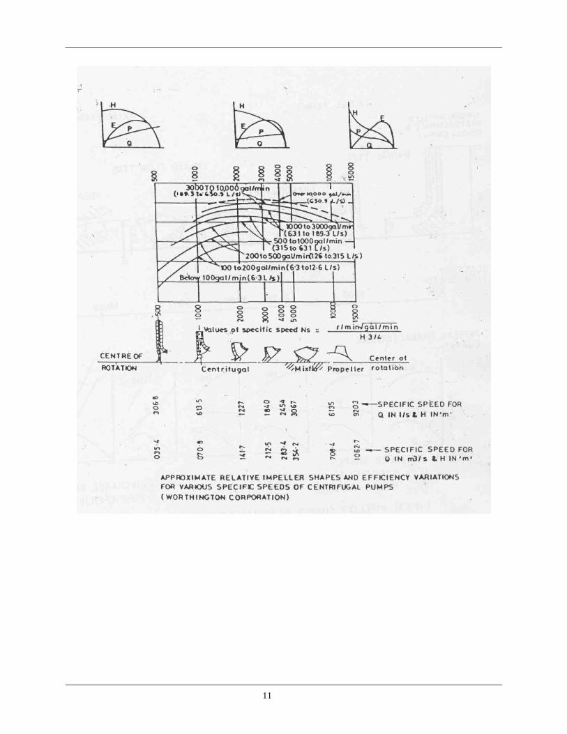
One of the figures which gives a good measure of the type and characteristics of a pump and a ready means of comparing one pump with another is what is known as 'specific speed'. It is merely an index or number which indicates the speed at which a reduced size of impeller geometrically similar to that of the actual pump would have to run to raise unit volume of water in unit time through unit head.
The performance of a pump/is expressed in terms of pump speed, total head and flow rate. Specific speed is calculated from the formula using the data at the best efficiency point as follows:
Specific speed (Ns) = (N√Q)/ H¾ where,
N = Speed of the pump in rpm,
Q = Flow rate in litres per second and,
H = total dynamic head in metres.
Specific speed relates to the geometry of the pump rotor and is independent of the pump size. When applying the above formula, it should be noted that,
(a) with double suction impeller half the best efficiency flow rate should be used.
(b) with multi-stage pump, best efficiency conditions for the first stage impeller only are considered in calculating the speed.
Normally range of specific speed is from 500 to 15000. The relationship between the basic impeller shape and specific speed and the corresponding characteristic curves relating head, power and efficiency for the particular types of impellers are given in figures 1 and 2.
It is instructive to note that lower specific speed numbers are associated with radial flow type of impellers having a comparatively large diameter but a small passage for water flow i.e. a narrow impeller. As the specific speed number increases, the diameter of the impeller decreases but the width of the water passage increases. 1.6.1 Units of specific speed Since specific speed is only an index or type number, certain liberties are permissible in selecting the units used. Consequently, the numerical value of Ns will vary according to the units in which H and Q are expressed. The speed of the impeller is always given in r.p.m.
The following table shows the relationship of specific speed in various units :
Metric (Ns)
British (Ns)
U.S.A. (Ns)
Q (l/s)H (m) Q (igpm) H(ft) Q (US gpm) H (ft)
I 1.5 1.63
10
11

where, igpm and US gpm stand for imperial gallons per minute and US gallons per minute. 1.6.2 Specific speed and pump type
By categorising centrifugal pumps in terms of specific speed, the pump user can visualise the type of pump he is likely to need.
For example, a pump is required to deliver 100 1/s at a head of 89m at 1450 rpm. using the equation,
1450 x (100) ½ Ns = ————————— = 500 893/4
12

This is fairly low specific speed radial flow pump. Hence, the user can expect a large pump with relatively low efficiency. However, if the speed is doubled to 2900 rpm the specific speed of the pump will be 1000. Consequently, the pump can be smaller with a higher efficiency which may allow a less powerful driver and, make the overall pump set package much less expensive.
Civil engineering costs would also be correspondingly reduced. Hence specific speed can be a valuable guide to the pump user in planning and designing a more cost effective pumping. 1.6.3 Specific speed and pump efficiency
The maximum attainable efficiency of centrifugal pumps depends to a great extent on pump geometry as categorized by specific speed. In general, the efficiency increases as the value of Ns rises. Figure 3 illustrates the relationship between pump efficiency and specific speed. The trend of the curve indicates that for economical operation very low values of NS are to be avoided; a condition that can be overcome by employing multistage pumps.
Fig 3. Specific speed and pump efficiency
13

2. TYPES OF PUMPS 2.0 CLASSIFICATION OF PUMPS
2.1 POSITIVE DISPLACEMENT PUMPS
'Reciprocating' and 'Rotary pumps' are called positive displacement pumps, because the medium pumped together with any air which may have entered into the suction pipe gets positively displaced from the suction side to the delivery side at every revolution.
A natural consequence of this is that its delivery pressure is not fixed as in a centrifugal pump, but will rise to high values if delivery becomes restricted. A centrifugal pump on the other hand builds up a definite maximum pressure determined by its speed and will work only when the pump casing and the suction pipe are entirely filled with water and no air has entered in.
2.2 ROTODYNAMIC PUMPS These pumps are rotary machines. Essential part of such pump is a rotor called impeller which is mounted on a shaft and is driven continuously in one direction. Formed on the impeller are blades or vanes so shaped that they increase the pressure of the liquid flowing between them, A fixed casing accommodates the rotor and conducts the liquid from the inlet branch of the pump to the outlet branch. The example of rotodynarnic pumps are 'centrifugal pumps'.
14

2.2.1 Centrifugal pumps
Fig. 1 Centrifugal pumps As the name implies, these pumps employ centrifugal force to lift liquids from a lower to a higher level. This type of pump in its simplest form comprises an impeller rotating in a volute casing. Liquid led into the centre of the impeller is picked up by the vanes and accelerated to high velocity by rotation of the impeller and discharged by centrifugal force at the periphery. When liquid is forced away from the centre, or as it is called the 'eye* of the impeller, a vacuum is created and more liquid flows in, consequently there is a constant flow through the pump. These pumps possess the following characteristic features on the basis of which they can be classified. - Working head. - Type of casing. - Construction of casing. - Number of impellers per shaft. - Relative direction of flow through impeller.
- Number of entrances to the impeller. - Disposition of shaft. - Liquid handled. - Specific speed and, - Method of drive.
15

Working head - Low lift. - Medium lift. - High lift.
Type of casing - Volute - Diffusion
Construction of Casing - Vertically split - horizontally split.
Number of Impellers - Single stage - Multi stage
Relative direction of flow through impeller - Radial flow - Axial flow - Mixed flow
Number of entrances to the impeller - Single entry - Double entry
Disposition of shaft - Horizontal - Vertical
Liquid handled
Depending on the type and viscosity of liquid to be pumped, the pump may have a closed or upon impeller. Specific speed Each type of impeller has a range of specific speeds for which it is best suited, though these ranges are only approximate. There are no sharp dividing lines for demarcation between these types. The range of specific speed for radial type impeller is generally 10 to 60 and for mixed flow type impeller it is usually between 90 and 160.
Method of Drive - Monoblock.
- Separate drive.
16

Volute Casing In the volute type pump , which is the one most commonly used, the impeller discharges into a progressively expanding spiral casing. This casing is so proportioned as to produce equal velocity flow all around its circumference and to reduce gradually the velocity of the liquid as it flows from the impeller to the discharge thus changing velocity head into pressure head.
Single stage pumps Centrifugal pumps with single closed type impeller with single suction is called single stage pumps. These types of pumps are generally used for small lifts like in agricultural activities when the head is less than 20 mts,
Multistage pumps These pumps are used when sufficient head cannot be developed efficiently in single stage. These pumps may have two or more impellers operating in series i.e. the discharge of one impeller is connected to the suction of another. The number of impellers in series will depend upon the head against which the pump must operate, the impeller diameter, the capacity of the pump and its speed.
Advantages of Centrifugal pump
In addition to the fact that the centrifugal pumps are available in wide range of capacities, the other advantages are -
* Simple in construction and easy to operate.
* Relatively low initial and maintenance cost.
* Comparatively silent in operation and makes less vibration.
* Very dependable and durable.
* Compact and requires less floor area for its foundation.
* Uniform and continuous flow.
* Capable of delivering large quantity of water as compared to its size and can handle sandy, gritty, and muddy water without injuring the pump.
* Suitable for high speed operation with an electric motor. No wasteful speed-reduction device is necessary.
* High efficiency.
* Can run for short periods with the delivery valve closed.
Relationship between Head, Quantity, Speed and Power absorbed in a centrifugal pump
a) Variation of impeller diameter with speed remaining constant , - Capacity varies directly as the diameter. - Head varies as the square of the diameter. - BHP varies as the cube of the diameter.
17

b) Variation of speed with impeller, diameter, remaining constant
- Capacity varies directly as the speed.
- Head varies as the square of the speed. - BHP varies as the cube of the speed. Comparison between Horizontal Spindle(HS) and Vertical Spindle (VS) pump
HS Pump VS Pump
Capital cost Less More
Attendant Must, Because it requires priming
Not necessary. It is may be set to run automatically
Operating cost More Less
Troubles & defects More Less
Requirement of maintenance work
More Less
Time and manpower required for attending troubles & defects
More Less
Limitations for use Cannot be used where suction lift is more than certain specified value.
No problem of suction lift, but the pump bowl must be, submerged in water completely i.e. not suitable where depth of water is less.
Very difficult to use where the water level is much below the ground level.
suitable where water is much below the ground level.
Trouble-some to use where there is much variation on water level due to seasonal effect.
Suitable for use where there is variation in water level due to seasonal effect.
Trouble shooting of centrifugal pumps
(a) No liquid delivered - Lack of priming. - Speed of pump drive too low. - Discharge head too high. - Suction lift too high. - Impeller plugged. - Wrong direction of rotation.
18

(b) Not enough liquid delivered - Air leaks - Low NPSH - Wrong bearing rings. - Worn bearing rings. - Damaged impeller. - Undersize foot valve. - Wrong direction of rotation. - Viscosity too high. - Wrong gaskets. - Impeller eye too small.
(c) Pump discharge pressure low - Gas or air in liquid. - Impeller diameter too small.
(d) Pump looses prime after starting - Incomplete priming. - Too high a suction lift. - Air leaks in the suction pipe or packing glands. - Gas or air in the liquid. - Suction line not filled with liquid. - Air or vapour pockets in the suction line. - Inlet not sufficiently submerged. - Low available NPSH. - Plugged seal-liquid piping. - Misplaced lantern ring in the stuffing box.
(e) Pump overloads driver - Discharge head low. - Wrong liquid. - Speed too high or wrong direction of rotation. - Packing too tight. - Distorted casing. - Bent shaft. - Mechanical failures. - Misalignment. - Pump speed too high,
19

(f) Excessive vibration - Gas or air in the liquid leads to a starved suction as do insufficient NPSH. - Pump misalignment. - Worn or loose bearings. - Rotor unbalanced due to plugged or damaged impeller. - Bent shaft. - Improper positioning of control valve in the discharge. - Non rigid foundation,
(g) Bearing overheat - Too low an oil level. - Poor or wrong grade of oil. - Dirt in the bearings or the oil. - Moisture in the oil. - Clogged or scaled oil cooler. - Failure of the oiling system. - Not enough bearing cooling water. - Bearings too tight. - Oil seals fitted too closely on the shaft,
(h) Bearings wear rapidly - Misalignment. - Bent shaft. - Vibration. - Excessive thrust from a mechanical failure inside the pump. - Lack of lubrication. - Wrong bearing installation procedures. - Dirt in the bearings. - Moisture in the oil. - Excessive cooling of the bearings. 2.2.2 Turbine Pumps
The chief difference between centrifugal and turbine pump is in the impeller. The water in a turbine pump also called regenerative pump is admitted not at the centre of the impeller, but through an outside opening on the casing,
The impeller has series of blades/vanes fixed on its outer rim, which revolve inside an annular space within the case in the clockwise direction. Water enters at the outer edge of the
20

impeller and is propelled forward round the pump case through the annular channel, which is much larger than the width of the blades. As the water is carried along, it moves spirally from one blade to the following one, until one revolution, when it is diverted by a deflector plate to the discharge opening.
Different types of impellers are used in this type of pump. They are semi open type and enclosed type. The impellers are usually made of cast iron or bronze, depending upon requirements and preferences. The passage ways through the impellers and diffusers are so designed as to give streamline flow and ensure smooth and efficient operation.
Liquid entering a centrifugal pump's impeller can pass between its vanes only once. It has energy added to it only while going from the impeller's eye to its rim. In a turbine pump, liquid recirculates between the impeller's vanes. Because of this action, the fluid flows in a path like a screw thread (helical) as it is carried forward. Consequently, energy is added to the fluid in a number of impulses by the impeller's vanes as it travels from suction to discharge. These impulses have the same effect as multistaging in a centrifugal pump. A turbine pump can develop several times the discharge pressure of a centrifugal type, having equal impeller and speed. For high pressure, multistage pumps are used. Turbine pump is self-priming once it is filled with water. That is, any air entering it subsequently through the suction is carried alongwith the water and delivered through the delivery pipe, whereas in a centrifugal pump entry of air into the suction would make it inoperative.
Power for a turbine pump reaches maximum at shut off, where it is the lowest on a centrifugal pump. Therefore, turbine pumps should not be operated against a closed discharge, unless a relief valve is provided.
Turbine pumps have come into wide use for both shallow and deep wells. These are built for heads upto 300 Mts and for capacities upto 27000 LPM. A cross section of a pump is shown in fig.2.
Fig. 2 : Turbine Pump
21

Fig. 2a. Pressure produced by a turbine pump increases uniformly around the impeller, from suction to discharge
FIG. 2b. Cross section through a turbine pump. Vanes cut in the periphery of. the impeller revolve in
an annular channel where pressure is produced by helical rotation of the liquid.
22

Vertical Turbine pump
These pumps are designed for vertical operation and find their application in various fields where centrifugal pumps can not be used either due to their limited suction capacity or due to medium capacity demands.
A centrifugal pump has got the problem of limited suction lift capacity i.e.' 6.6 metres. If the water is to be lifted from depths more than 6.6 metres, the entire pump is to be lowered in the well . The alternative method is to lower the pump portion in the casing pipe of the well as in the case of V.T. Pump and keep the motor above the ground level having an extended shaft upto the pump. The shaft is coaxially contained in a column pipe which serves dual purpose of water delivery and supporting base for stationary parts of the pump. These are the best pumps, for pumping water to cities and towns from river or deep tube wells. Vertical turbine pumps are available from 70 litres per minute to 6 lakhs litres per minute, at heads of 5 to 300 metres and horse power upto 200 with bowl diameters 75 mm to 1.5 metres and casing pipes of equivalent external diameter. Vertical turbine pump has got three distinct sections as shown in Fig. 3 viz. bowl assembly, head assembly and column assembly.
Fig. 3 : Vertical Turbine Pump
23

Vertical turbine pumps are of two types viz., * Oil lubricated. * Water lubricated.
Trouble shooting of Vertical Turbine Pumps
(I) Pump won’t start
(A) Faulty wiring or motor * Check current characteristics with data on motor nameplate * Check wiring with diagram and data on motor nameplate. * Be sure starter is properly connected and correct for horsepower and
voltage. * Check fuses or circuit breaker for open power line. * Reset starter overload relays, if tripped. * Check remote-control stations for possible open circuit. * If motor fails to operate independently of pump with all wiring correct,
inspect it for winding failure.
(B) Excessive bearing friction * Use SAE-10 or equivalent oil at pumping temperature on enclosed
shaft of oil lubricated pumps. Lubricate all the bearings before operation.
* On oil lubricated pumps, lack of proper tension on the shaft enclosing tube may allow misalignment of the bearings. Be sure that tube tension nut is tight.
* Be sure enclosing tube spiders(stabilizers) are properly located in column assembly.
* Rubber bearings in water lubricated units may seize if dry. Lubricate before starting.
* Bent shafts must be replaced. * A crooked well causing misalignment must be straightened or a pump
installed of small enough diameter to hang freely in the well. * Check for misalignment caused by crossed threads or burred finished
surfaces. Improper anchoring of head can cause distortion and bending of pump.
(C) Incorrect impeller adjustment * Set impellers high enough to allow for shaft stretch due to hydraulic
thrust. When adjustment allows shaft to turn freely, stretch caused by shaft and rotor weight have been taken care of. Additional clearance may be necessary to allow for shaft stretch during pumping caused by hydraulic thrust. If adjustment is too high impellers may rub.
24
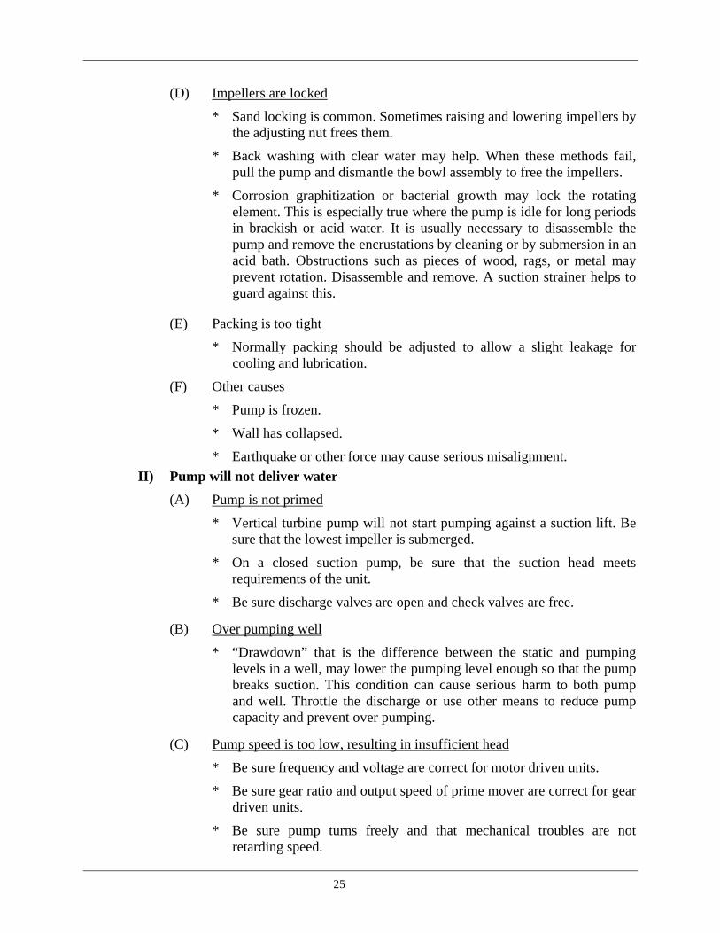
(D) Impellers are locked
* Sand locking is common. Sometimes raising and lowering impellers by the adjusting nut frees them.
* Back washing with clear water may help. When these methods fail, pull the pump and dismantle the bowl assembly to free the impellers.
* Corrosion graphitization or bacterial growth may lock the rotating element. This is especially true where the pump is idle for long periods in brackish or acid water. It is usually necessary to disassemble the pump and remove the encrustations by cleaning or by submersion in an acid bath. Obstructions such as pieces of wood, rags, or metal may prevent rotation. Disassemble and remove. A suction strainer helps to guard against this.
(E) Packing is too tight
* Normally packing should be adjusted to allow a slight leakage for cooling and lubrication.
(F) Other causes
* Pump is frozen.
* Wall has collapsed.
* Earthquake or other force may cause serious misalignment. II) Pump will not deliver water
(A) Pump is not primed
* Vertical turbine pump will not start pumping against a suction lift. Be sure that the lowest impeller is submerged.
* On a closed suction pump, be sure that the suction head meets requirements of the unit.
* Be sure discharge valves are open and check valves are free.
(B) Over pumping well
* “Drawdown” that is the difference between the static and pumping levels in a well, may lower the pumping level enough so that the pump breaks suction. This condition can cause serious harm to both pump and well. Throttle the discharge or use other means to reduce pump capacity and prevent over pumping.
(C) Pump speed is too low, resulting in insufficient head
* Be sure frequency and voltage are correct for motor driven units.
* Be sure gear ratio and output speed of prime mover are correct for gear driven units.
* Be sure pump turns freely and that mechanical troubles are not retarding speed.
25

(D) Suction is clogged * Make sure that the strainer, suction pipe and impellers are not clogged.
Back washing may clear. * Well screens may be clogged and require the services of a competent
well man. (E) Mechanical failure * Check for broken shaft and replace. * Make sure none of the impellers are loose. * All column pipe joints must be tight to eliminate excessive leakage. * Check bowl assembly and make sure it is not broken. Ill) Capacity too low
(A) Head is too high * Centrifugal pump performance is such that an increase in head results
in a decrease in capacity. Conversely decreased head increases capacity.
(B) Poor suction conditions * Pit. or sump must be properly designed so that liquid velocities and
suction submergence are in accordance with recommendation. Baffling or other modifications may be all that is necessary.
* Aerated or gaseous water has the effect of reducing capacity. * Check suction piping for air leaks, * Be sure that the suction head on closed suction pumps is correct. * Check for obstructions in strainer suction pipe and bowls. * Check for partial clogging of water passages because of corrosion,
bacterial growth or other causes.
(C) Leakage * Tighten all pipe threads and flanges. * Replace worn gaskets or packing. * Be sure that there are no cracks or holes in column pipe, bowl
assembly or discharge head.
(D) Incorrect impeller adjustment * Operating clearances of semi-open impellers must be close. To obtain
maximum capacity, be sure impellers are adjusted as close as possible to the bottom of their castings, otherwise slippage reduces pump capacity.
(E) Mechanical failures * Worn impellers or wearing rings allow slippage, which reduces
capacity. A slight increase in capacity can sometimes be obtained by resetting the impeller adjustment for operation closer to the bowls, but if parts are badly worn, replacement is necessary.
26

* On enclosed shaft pumps, worn bearings below the relief vent in the discharge casing may allow excessive leakage through the vent and cause reduced discharge capacity.
* Impellers loose on pump shaft.
(F) Defective test equipment * Make sure that the water level when pumping is accurately determined. * Calibrate pressure gauge. * Check accuracy of capacity measuring devices.
IV) Too much power
(A) Operating condition different from those for which pump is designed * Check pump curves, If conditions can not be corrected to reduce power
required by the pump, a large motor may be needed. * Speed of gear or belt driven pumps can often be reduced to lower the
horse power. This also reduces pump capacity and head. * Diameter of most impellers can be cut down to reduce horse power
which also reduces capacity and head. * Where there is a wide difference between actual operating and pump
design conditions, it may be necessary to change the pump.
(B) Speed too high, resulting in over capacity and higher head * Reverse of too low speed See IIC, 1,2 and 3
(C) Liquid different from that for which pump is designed * Higher specific gravity may require a larger motor. * Higher viscosities can sometimes be corrected by heating the liquid. * Air or gas in the water can cause cavitation. * Increased submergence, lower inlet velocity, or other suction changes
may help correct trouble. * Sand in water may indicate that suction area needs cleaning out. Wells
may require new screens or sand pumping to develop water bearing strata.
(D) Impeller rub because of incorrect adjustment * See I (C).
(E) Lubrication is incorrect * Check for proper quantity and viscosity of oil in oil-lubricated pumps. * Be sure that liquid is lubricating all bearings.
27

V. Pump vibrates
(A) Misalignment
* Check for misalignment as listed for I (B) 5,6 and 7.
(B) Bearing failure
* Be sure that lubrication is correct.
* Check for excessive sand in water.
* Correct pump alignment.
(C) Poor suction conditions
* Correct possible cavitation. (See III (B) 1,3,4, and 5)
(D) Unbalance
* Operate driver alone to see if it vibrates.
* Check for foreign material lodged in impeller or bowl passages. Such material might cause both static and hydraulic unbalance.
* Check rotating parts for excessive wear. Excessive abrasive in water can change water passages and cause hydraulic unbalance. Wear also changes static balance.
VI. Water in the shaft enclosing tube
(A) Enclosing tube failure
* Replace broken or leaking sections.
* Renew broken or loose bearings.
* Be sure that all joints are tight flush.
* Ensure no cuts or dents on the tube faces.
(B) Failure in bowls
* Make sure that discharge case vent is not plugged.
* Be sure that bearing below vent is not worn or scored, allowing excessive pressure on vent.
* Check pump shaft for wear that would produce excessive bearing clearance.
* Be sure that bearing above vent is not worn or scored, allowing any excessive leakage to go into enclosing tube instead of going through vent.
28

2.2.3. Submersible motor pumps In submersible motor pump sets, both pump and the unusually long, small diameter motor are installed deep inside the tube well so that suction lift is minimized which make it possible to lift water from depths as low as 450 metres. These pumps are essentially single or multistage centrifugal turbine pumps designed to form a compact unit in conjunction with a coupled wet type squirrel cage induction motor both of which operate totally submerged below the surface of water. The main parts of a submersible pump set are shown in fig.4.
Fig. 4 : Submersible pump
A submarine armoured cable and a small copper oil tube form the only connection beside the discharge pipe between the pumping unit and the surface of the ground.
The motor is a squirrel cage induction type motor and the rotor is carried on two ball bearings, one of which is a radial thrust bearing to take both the weight of the rotating parts and
29

the hydraulic load. The other ball bearing is of radial type, and its chief function is to centre the rotor. A high dielectric oil is circulated through the entire windings at all times and, although a small copper tube affords a means for replenishing the oil supply, motors have operated continuously for several years without having the oil supply added to or changed. Water is sealed out at the top by mercury in a rotating cup that is attached to motor shaft. A cylindrical sleeve is placed around the motor shaft, with one end attached to the motor casing and the other end submerged in the mercury. Thus the water and the motor oil are sealed off on their respective sides.
In another design of submersible pump, the pump is of centrifugal type with diffusion vanes, built in varying numbers of stages with bronze impellers to meet head requirements. The rotor of the motor, which is of the squirrel cage type, operates in the water, but the stator is completely protected from the water by a rust proof stainless steel cylinder. The motor runs extremely cool because the stator is surrounded by water. Such motor has bearings separately enclosed in its own grease chamber and require greasing only after several thousand hours of operation.
Submersible pumps with radial flow impellers are made for low discharge with high total heads, whereas pumps with mixed flow type impellers are made for medium discharge range with medium heads.
This type of pump initially found most versatile use in naval applications for salvaging purpose and then gained popularity for deep well applications. Now a days, they occupy pioneering position in deep well pumping and are becoming extremely popular in surface pumping like cooling water circulation and ornamental fountains. Advantages of submersible pumps
Easy to install
Installation requires no foundation. The unit with pipe is held by supporting clamps which rest on upper edge of the casing pipe. Instead of pump-house, a small well-head covered with a lid is constructed to prevent contamination of water. Thus construction of pump room can be dispensed with.
No suction trouble As the pump rests below water level, flow inside the pump is automatic and no suction difficulties arise. There are no glands hence there is no leakage in the pump.
No Maintenance As the bearings are water lubricated, periodical oiling or greasing is not needed. This also eliminates contamination of water with grease.
Noiseless operation
As the pump is of centrifugal design, it is nearly noiseless in operation. Since both pump and motor are placed deep down in the well, there is no disturbance from the pumping noise.
30

High efficiency (Economical) Overall efficiency of submersible pump is high than that of shaft type pump, and the higher is the pump efficiency the lower is the power consumption, which means lower cost of operation. As submersible pump operates over a range of loads, rated capacity of the motor has to be high enough to avoid over loading during the period of maximum load. The pump can be controlled manually or automatically depending on the installation.
Quick starting
The slim rotor design effects quick starting since the internal mass (inertia) of rotor is very low.
Comparison of submersible pump with vertical turbine pump
Both the pumps are almost identical. However, the motor of submersible pump is costlier than that of V.T. pump.
The installation of a V.T. pump requires services of an experienced mechanic because perfect alignment of vertical column pipe and the rotating line shaft is essential.
Submersible pump can be installed even in the bores which are not exactly vertical, whereas V.T. pump cannot be installed in such circumstances.
The vertical turbine pump and its motor are slightly more efficient than the submersible pump and its motor. If the friction losses and shaft losses in V.T. pumps are added then both the systems require the same cost. In case of oil lubricated V.T. pump, oiling of the shaft is an additional recurring expenditure.
In case of dry motor type submersible pump, the efficiency of motor is very poor owing to unavoidable losses due to eddy currents in the shell and friction losses due to viscosity of the liquid circulating in the clearance between rotor and shell.
The heating up of the wet type motor while running and cooling down when stopped causes expansion and contraction of the liquid inside the motor. This in turn results in water containing sand being frequently sucked into the motor from the bore hole. Prevention of this complicates the design and increases the losses. The life expectancy of submersible motor depends upon the type of insulation.
As is very clear, submersible pumps should be used in places where electric supply is available at fairly constant voltage supply as motor is under great depth and considerable voltage drop may occur in the cable itself.
The chances of break-down and repairs are more in V.T. pumps, as it has got various mechanical elements like lengthy shaft, bearing spider etc.
Submersible pump has more degree of reliability except for the trouble in motor.
31

Vertical turbine pumps are low speed machines and are, therefore, less subject to routine wear. They are-generally designed for 1450 rpm, whereas submersible pumps are always designed for 3000 rpm because of the limitation of diameter.
In submersible pumps, if the motor gets burnt, it may take more time to resume the water supply. This is due to the time span required in rewinding the motor, which is atleast 48 hours. Therefore it becomes compulsory to keep one spare motor.
Calculations have shown that V.T. pump is more economical in power consumption if the depth is not more than 30 metres, beyond which submersible pump is more economical. V.T. pumps are rotated by a line shaft which involves higher cost and loss of power due to friction, particularly if its length is too large. Due to this reason they are more suitable for shallow settings upto 30 m and are never used beyond 45 m depth. "
Since tube-wells are generally dug in remote areas or in public places, pumps installed at such places are not secured against pilferage and sabotage. Since submersible pump and its motor are totally submerged under water and only starter remains outside, pilferage and sabotage are avoided. The overall efficiency of most submersible pumps ranges between 52 to 60 per cent, while the overall efficiency of vertical turbine sets range between 75 and 77 per cent. Trouble shooting of submersible pumps
Pump fails to start * This may be due to blown fuses, short circuiting or a heavy load on the pump.
* Remedies will include precise testing, diagnosing the trouble and taking remedial measures.
Pump starts but low discharge or no discharge at all * The motor is running in the reverse direction.
* The pump is operating against a head greater than its rated capacity.
* The pump suction is blocked by foreign matter, salt deposits or collapse of the bore.
* The pump is air-locked (no discharge at all).
* The reflux valve above the pump is jammed or the riser pipe closed by obstruction or by the valve.
* Voltage or frequency is considerably lower than required.
Pump runs and discharges steadily but the discharge is below normal
* Fault in power supply,
* Mechanical friction in pump or motor,
32

* Riser pipe developing a hole or a leak developing in the system below the ground level.
* The pump being worn by sand, there is an increase in mechanical friction.
Pump runs and discharges intermittently and air bubbles are present in the discharge
* This means that the pumping rate is greater than the rate of recuperation of the well. If allowed to persist, this may cause damage to the pump, shaft keys, couplings and motor.
2.3 SPECIAL EFFECT PUMPS
2.3.1 Ejecto (Jet) pumps
One of the major drawbacks of centrifugal pump is the limitation of suction lift. To overcome this drawback, deep well, turbine pumps and submersible pumps were developed. However, these necessitate conveyance of power from the top of the well upto the deeply immersed moving parts. Installation, servicing and, maintenance of these pumps are time consuming. These difficulties have been overcome in Ejecto pumps, which are otherwise known as jet pumps. There is no transmission of either mechanical energy or electrical energy from top of the well to the standing water level.
Ejecto pump (Fig 5) is based on the principle of conversion of hydraulic energy from one form to another form.' When high pressure water is passed through a converging passage, the pressure head is converted into velocity head. Similarly, when water having high velocity head is passed through a diverging passage, it gets converted into pressure head. The high velocity water entering the venturi throat impinges against the slow moving water coming from the well. An exchange of momentum takes place and a low pressure area is developed near the throat and an average velocity is established in the mixing zone of the venturi. Thus, suction can be created inside the throat region of venturi submerged in water. Water sucked can mix with high velocity water, which can be again convened into pressure head, enabling the water to rise up. The principle of ejecto pump can be summed up as, - Creating partial vacuum and lifting water from the well. - Imparting sufficient pressure energy to water so that it is raised from the depth to
the desired level.
33

Fig. 5 : Ejecto Pump
Advantages of Ejecto pumps
Offset installation
This is a unique feature of Ejecto pump. It can be installed away from the source of water upto a distance of 90 m or even more.
Deep-well turbine and reciprocating deep-well pumps have to be installed on the well in a strictly vertical position because of their construction feature. In case of centrifugal and shallow-well reciprocating pumps, the offset distance is very much limited. This is because as the distance increase, friction losses increase and hence the suction lift is affected. In case of these pumps, suction lift is limited upto 6.6 m. Hence, the offset installation is also restricted. In case of the present series of ejecto pumps, the maximum suction lift can be upto 85m. Hence off-set installation at greater distance is possible.
Normally ejecto pump's capacities are based on 1.5m off-set. When the offset increases, the capacity decreases slightly, but this can be eliminated by using larger diameter pipe, Theoretically, it is possible to use larger pipe and arrange offset beyond 90m, but great care has to be taken to provide steady slope of pipe towards the well so that no air is entrapped, and all joints should be absolutely air tight under vacuum condition. Depending upon the suction lift and the offset distance, proper size of 'pipes can be selected.
Offset installation saves installation and maintenance trouble considerably. Pump can be located at a convenient place and taken care of properly.
34

Since the pump can be installed away from the source, installation becomes very easy. Moreover, as there is no rotating part inside ejecto assembly to be submerged in water, it can be even installed on crooked well,
Easy to maintain As the pump can be installed at a convenient place away from the well source, maintenance becomes very easy due to easy accessibility.
Trouble-free performance Normally all important parts are made of materials like bronze, stainless steel, etc. which can withstand corrosion, wear and tear. All rotors are dynamically balanced, thereby minimizing noise and increasing bearing life. Air lift pumps Another method of pumping from wells is by air lifts with compressed air being admitted to the well to lift water to the surface. For successful operation of the system, the discharge pipe must have its lower end submerged in the well water. The amount of submergence before air is admitted will vary from 70% for 60 M lifts to 40% for 210 M lifts. When air is admitted to a well the water recedes from the level of static head to the bottom of the discharge pipe. The displaced column of liquid rises up the discharge pipe and as the air flow continues, it enters the pipe, aerating the water and lowering the specific gravity the mixture. Pressure in the well is momentarily decreased and increased as the bottom end of the pipe is uncovered and covered. The cycle repeats rapidly, producing a nearly constant flow from the for of the discharge pipe.
35

3. CHARACTERISTICS OF CENTRIFUGAL PUMPS
3.0 INTRODUCTION
Pump is usually designed for one speed, flow rate or discharge and, head, but in actual practice the operation may be at some other condition of head or discharge and for the changed conditions, the behaviour of the pump may be quite different. If the flow through the pump is less than the designed quantity, the value of the velocity of flow of liquid through the impeller will be changed, thereby changing the head developed by the pump and at the same time the losses will increase so that the efficiency of the pump will be lowered. Therefore, in order to predict the behaviour and performance of a pump under varying conditions, tests are performed and the results of the tests are plotted. The curves thus obtained are known as the characteristic curves and are usually prepared for the centrifugal pumps. These curves can be classified into three categories as under:
• Main and operating characteristics,
• ISO-efficiency (constant efficiency) curves,
• Constant Head and constant discharge curves. 3.1 MAIN AND OPERATING CHARACTERISTICS
3.1.1 Main characteristics
In order to obtain the main characteristics curve of a pump, it is operated at different speeds. For each speed, the rate of flow or discharge (Q) is varied by means of progressively closing or opening of a delivery valve and for the different values of Q, the corresponding values of total head (H), shaft power (P) and the overall efficiency are measured or calculated. The same operation is repeated for different speeds of the pump. Then the following curves are plotted.
• Head - Discharge characteristics i.e. H Vs Q.
• Power- Discharge characteristics i.e. P Vs Q.
• Efficiency - Discharge characteristics i.e. Efficiency Vs Q.
The three curves referred to, arc plotted below in fig. 1. They represent the main characteristics of a pump. The main characteristics are useful in indicating the performance of a pump at different speeds.
36

Fig 1 Main characteristics of a centrifugal pump
3.1.2 Operating characteristics During its working, a pump is normally required to run at a constant speed, which is its design speed and same as the speed of its driving A.C. induction motor or diesel engine. As 'such that particular set of main characteristics which correspond to the designed speed are mostly used in the operation of a pump and are therefore, known as the operating characteristics, A typical set of such characteristics of a pump is shown in fig. 2. The values of head and discharge corresponding to the maximum efficiency are known as the normal (or designed) head and the normal (or designed) discharge of a pump. The head corresponding to zero or no discharge is known as the "Shut-off head" of the pump. From these characteristics, it is possible to determine whether the pump will handle the necessary quantity of liquid against the desired head and what will happen if the head is increased or decreased. The P Vs Q curve will show what size of motor will be required to operate the pump at the required conditions and whether of not the motor will be over loaded under any other operating conditions. 3.2 ISO (CONSTANT) EFFICIENCY CURVES
As shown below in fig. 3, constant of ISO-efficiency curves may be obtained from H-Q and Efficiency - Q curves of fig. 2,
In order to plot the ISO-efficiency curves, horizontal lines representing constant efficiencies are drawn on the Efficiency - Q curves. The points at which these lines cut the efficiency curves at various speeds, are transferred to the corresponding H-Q curves. The points corresponding to the same efficiency are then joined by smooth curves which represent the ISO-
37

efficiency curves. From these curves, the line of maximum efficiency as shown in Fig. 3 may be obtained. The ISO-efficiency facilitate the direct determination of the range of operation of a pump with a particular efficiency, Stated another way, they evaluate the minimum and maximum percentage flows that would maintain the efficiency within say 2 % of the maximum efficiency at the design point.
Fig. 2. Operating characteristic curve of a centrifugal pump
Fig. 3. Constant efficiency of a centrifugal pump
3.3 CONSTANT S HEAD AND CONSTANT DISCHARGE CURVE These curves are useful in determining the performance of a variable speed pump to which the operating speed constantly varies. Characteristics of a pump under varying speeds with one of the parameters viz. Head or Discharge being maintained constant, give interesting insights into the performance of a pump. These are shown in Fig. 4 below.
38

Fig. 4 Q-N, H-N, and P-N curves of pump
It may be seen from the curves that, • With head remaining constant the discharge of the pump varies linearly with speed
and characteristics are a straight line. • With discharge remaining constant, the head developed by the pump varies as the
square of the speed and characteristics is a parabola. • With the discharge valve opening remaining constant, the power demand of the
pump varies as the cube of the speed.. 3.4 PUMP CHARACTERISTICS ON PERCENTAGE BASIS It is indeed very instructive to express all the variables such as H, Q, N etc. constituting the characteristics as a percentage of their values at the design point ( duty point). This method will have the additional convenience of permitting a numerical flow. A percentage flow of 56 will mean that the discharge is 56% of normal or designed flow, a percentage flow of 145 will signify a fairly extreme state of increased flow. The operating characteristics of a centrifugal pump and their representation in percentage terms are shown in Fig. 5.
Fig. 5. Centrifugal pump Characteristics
39

3.5 SIMILARITY OR AFFINITY LAWS FOR CENTRIFUGAL PUMPS
The Head,Capacity and, b.h.p. of a pump vary with speed in such a way that the performance curves retain their characteristics features. The variation follows laws known as AFFINITY or SIMILARITY LAWS. Applicable to any point in the Head-Capacity curve, these laws state that to a given pump, when speed is changed. • Capacity varies directly as the speed. • Head varies directly as the square of the speed and, • B.h.p. varies directly as the cube of the speed.
In a given centrifugal pump, to a given speed, the affinity law states that at constant rotational speed, • Capacity is directly proportional to the impeller diameter. • Head is directly proportional to the square of the impeller diameter. • B.h.p. is directly proportional to the cube of the impeller diameter.
The above statements can be represented mathematically as under for two different conditions.
Impeller diameter constant to a given pump at 2 different speeds
Speed constant i.e. for a given pump with 2 different impeller diameters
Q 2 N 2 ------------ = ------------ Q 1 N 1
Q 2 D2 ------------ = ------------ Q 1 D1
H 2 N 22
------------ = ------------ H 1 N 12
H 2 D22
------------ = ------------ H 1 D1
2
BHP 2 N 23
------------ = ------------ BHP 1 N 13
BHP 2 D23
------------ = ------------ BHP 1 D1
3
40

4. SYSTEM HEAD CHARACTERISTICS 4. 0. Introduction
In the earlier chapter the performance characteristic inter alia covering the shape and nature of the H.Q. i.e. head discharge characteristics as well as efficiency and power consumption characteristics of the entire gamut of radial, mixed flow and axial flow centrifugal pumps of varying specific speeds were discussed. While discussing these , the subject of the total head against which a pump has to function was also discussed. It was observed that all the ingredients or components that go into and add up to the total head are all factors totally external to the pump. The constituent like the total static head or the pipe friction head etc. could vary according to the type of installation. For instance the high service tank could be at a lower or higher level or the length of the pipe line could be more or less depending on the needs of the installation, without in any way affecting the pump and its characteristics one single bit. It may therefore, readily be appreciated that in a pumping installation, there are 2 distinct and independent components namely: (1) The pump with its own Head-Discharge characteristics at the operating speed and (2) The sump, the overhead tank, the piping and associated fittings,
the inlet and exit points - the sum total of which manifests its own characteristics.
In order therefore, to set up a satisfactory pumping installation with a certain desired rate of flow, there has to be a proper matching of the pump and the system in which it operates to be able to attain the overall objective of the installation in an efficient manner. In this chapter the system and its characteristics and the impact of the variations in the characteristics on the output of the pump are discussed. 4.1 System Head Curve
The total head against which a pump has to operate, as discussed in the last chapter comprises of:
1. Total Static Head Given by the difference in level between the suction-sump and the highest point in the delivery piping. This difference in level is independent of the flow-rate of pumping. At best any changes in it occur only when the water level in the suction, sump encounters some seasonal variation and there is a high water level and a low water level (LWL) in which case the higher static head occurring at LWL is taken into the total static water head.
2. Friction Head: This is the sum of the head losses in the entire length of the piping, from the foot valve to the final point of delivery piping, also the losses in all the valves, in the foot-valve, the non-return value and the isolating (generally. sluice or butterfly) valves and the losses in all pipe fittings such as bends, toes elbows,
41

reducers etc. The friction head varies as the square of the velocity of flow and may be expressed as a general equation
K.V2 H = ———— 2g
The total head of the system = static head + Friction head = Hs +Hf
It may be seen that the static head is a fixed quantity, and the friction head a variable quantity. Its value varying as the square of the velocity of flow in the piping system which in turn varies with the quantity of discharge or rate of flow. If the friction heads above were to be plotted on a set of co-ordination it will be a parabola passing through the origin (Fig 1)
Fig. 1 If the total head-is plotted, then the static head is a horizontal line parallel to the X-axis. The friction head will then take off at intersection of Y- axis and the static head line. This curve indicates the total head exhibited by the system for varying rate of flow.
42

4. 2. Effect of Change to System Head Curve
In Fig. 2 are plotted the Head vs. Discharge characteristic of a pump as well as the system Head Curve. The point of intersection A of the system head curve with the H.Q of the pump is the operating point of the pump.
Fig. 2 The system head curve will change by any changes made in the system such as: i) Change in length or size of the piping ii) Change in size & number of pipe-fittings iii) Change in size, number and type of valves iv) By operation of the valves, semi-open or full open
These changes will cause the system head curve to become steep or flat. For instance closing the delivery valve partly (or throttling the valve as it is called) would result in a new system head curve in fig. 2 giving a new operating point B, at the intersection with the H-Q
43

characteristic of the pump. If throttling is done further more, yet one more system head curve would arise intersecting the H-Q curve at C giving a new operating point.
It may be observed that the discharge of the pump has been reduced from point A to B and still further at point C. This is one of the methods of regulating the water output of a pump although a very inefficient one.
Resistance to flow by fittings values etc. The pressure, volume, and velocity of water passing through a pipe are affected in addition to the friction on the sides of the pipe by the friction in passing through valves and fittings. The estimates of this additional friction by different authorities vary considerably. The following two schedules are commonly used, which can be taken as a good working guide to estimate the friction losses caused by fittings or valves in a run of pipe, each fitting or valve causing additional friction equal to an additional length .of straight pipe.
Table 1.
Fittings Equivalent length of straight Pipe in meters
Sluice value full bore type Non-return value, full bore type Foot valve, full-bore type Strainer Bends
4.6 6.0 6.0 12.0 4.6
Valve / elbow / tee Equivalent length of straight pipe
Globe valve, open Angle valve open Gate valve open 90 Deg. elbow open 45 Deg. elbow Tee, straight through Tee, through side outlet
275 times the internal pipe dia 150 times the internal pipe dia 9 times the internal pipe dia 30 times the internal pipe dia 20 times the internal pipe dia 16 times the internal pipe dia 60 times the internal pipe dia
Except in congested areas, the head losses 'through fittings and gate valves are relatively small in relation to the pipe friction loss. When the length of pipe is greater than 1000 times its diameter, the loss of head due to valves and fittings may be disregarded.
44

Table No. 2
Head Loss due to Friction head losses in metre per 100 m length of CI used pipe line
Pipe diameter (mm) Discharge Litre/sec 150 175 200
18 1.0 0.4
20 1.5 0.6 0.25
22 1.6 0.7 0 3
24 1.8 0.8 0.4
26 2.2 1.0 0.5
28 2.3 1.2 0.55
30 2.8 1.3 0.6
35 4.0 1.8 0.85
40 5.0 2.5 1.1
45 7.0 3.0 1.5
50 7.8 3.5 1.7
55 10.0 4.5 2.2
60 12.0 5.0 2.5
6s 14.0 6.0 3.0
70 16.0 6.5 3.5
75 18.0 8,0 4.0
80 - 9.0 4.5
85 - 10.8 5.0
90 - 12.0 5.6
95 - 13.0 6.5
100 - 14.0 7.0
120 - 20.0 10.0
140 - - 14.0
45

5. DESIGN OF WATER SUPPLY PUMPING
INSTALLATIONS - BASIC CONSIDERATIONS 5.0 INTRODUCTION A mismatched water supply system wastes lot of energy. It is necessary to consider all factors effecting the proper design of pumping installations. Given below are various factors which should be taken into account at the time of designing water supply pumping installations. 5.1 BASIC CONSIDERATIONS The following are the basic considerations for the design of water supply pumping installation.
- Ascertain maximum daily consumption of water for the present and anticipated increased consumption for the next 5 years at least. The estimate should be made by considering each point of consumption for domestic, commercial, industrial use on the basis of accepted yard stick and past experience. The way and works manual of the Civil Engineering department gives the scale of daily supply ascertaining the requirement of water. In addition IS; 1172-1983 gives the same information which is shown in Annexure -I.
- For designing an efficient water supply system, it would be better if consumption of water is ascertained on an hourly basis. Plotting the requirement on hourly basis will greatly help in deciding the primary storage capacity (main overhead tank), secondary storage capacity (the small storage tank) available in each residential block and other points of consumption.
- Similarly the requirement of water in station premises for watering of carriages, for washing lines, workshops etc. should also be worked out on an hourly basis. The selection of pipelines for delivering water would thus become easy.
- After the total requirement of water has been worked out, it would be ascertained whether the water source available is adequate and continuous to meet the demand.
- Collect necessary hydraulic data for the source such as the highest and lowest water level recorded during the last 10 to 15 years.
- Finalise the locations of the pump house(s), diameter and route of the pipe line, locations "of overhead water tank(s) on the similar analogy as that of designing the electrical substations.
46

5.2 CAPACITY OF STORAGE TANK
Para 2517 of the 'Way and Works Manual says that the storage capacity should be equal to the higher of the following figures. a) With efficient standby pump: - One quarter of the maximum water consumption in 24 hrs. - One third of the normal water consumption in 24 hrs.
b) Without standby pump: - One third of the maximum water consumption in 24 hrs. - One half of the normal consumption in 24 hrs. . Local conditions should
however be considered when deciding on storage capacity.
5.3 CAPACITY (OUTPUT) OF PUMP For assessing the capacity of pumps to be provided at a particular installation, the following guidelines are provided in para 2514 of Way and Works Manual'. The pumping system should be capable of supply. In 12 hrs. of less, the normal quantity required in 24 hrs. In 16 hrs. or less, the present maximum quantity required in 24 hrs. In about 20 hrs. the estimated maximum future requirements in 24 hrs.
5.4 STANDBY PUMP A standby pump normally should be decided on the basis of importance of the water supply installations. Whether an installation should have a diesel engine driven pump or a DG set, should be decided after due consideration. Normally a well maintained pump set should not work more than 16 hours a day.
5.5 SELECTION OF PUMPS The selection of pump for particular application is influenced by system requirements, system layouts, water characteristics, intended life, energy cost and material of construction. Basically, a pump is expected to, - Pump a given capacity in given length of time. - Overcome the resistance in the form of head of pressure imposed by the system.
While calculating and selecting the type and size of pumps, the following hydraulic data is required to be taken into consideration. - Type of source viz., natural/artificial, perennial/seasonal. - Average yield. - Total daily requirement from the source. - Data of static water level and infiltration level below ground level during (a)
Monsoon or wet season (b) Dry season. - Diameter of pipe proposed to be used for suction side and delivery side as well as
the length of the delivery.
47

- No. of bends and valves and general layout of the pipe. No valves should be used on suction side.
- Height of the overhead tank from the ground level as well as the total storage capacity to be provided.
It is also necessary for checking the piping layout. It is not uncommon that whenever an old pump is replaced by a new pump, the discharge of the pump at the overhead tank is much below the rated capacity. This may be due to scale formation inside the pipe line, thereby reducing the diameter of pipe line.
A good method of testing the discharge of the pump is to measure the discharge over a specified time in the overhead tank by closing all the delivery, system of the tank. After taking number of such readings, calculate discharge per hour. This may be compared with the discharge at ground level by disconnecting the main delivery line and then computing the discharge at overhead tank level from the pump characteristic overhead tank level from the pump characteristics curves.
Water characteristics such as turbidity, contents of chlorides and total solids, PH value, temperature and sp. gravity are also important factors for consideration. The handling of water with different characteristics may present problems in the selection of pump. The characteristics of clear, cold and fresh water specified in IS: 1710 - 1981 are given below.
Turbidity 50 ppm (sillica scale) max. Chlorides 500 ppm max. Total solids 3000 ppm max. PH 6.5 to 8.5 Temperature 33°C, max. Specific gravity 1.004 max.
If the range of PH value of the water pumped is between 6.5 and 7.5 and also the chloride content is less than 100 ppm, the pump may be made of any bronze. However, if the range of PH is between 6.5 and 8.5 and the chloride content exceeds 100 ppm stainless steel construction shall be permitted.
The power required to drive the pump and suction lift depend on the sp. gravity of water. The suction life also gets reduced with the rise in temperature of the liquid. If any other characteristics of the water differ from those mentioned above, the pump details will have to be agreed between the manufacturer or supplier and the user and shall be specified in the order.
Materials are affected by both the water and environment. Resistance to corrosion and wear are the two important properties in this regard. Suitable material for pump can be selected keeping in mind the purpose and operating conditions.
5.6 SELECTION OF SUCTION/DELIVERY PIPE NETWORK
The route of the suction and delivery pipes should be measured and their diameter determined. The pipe lines should be free from scales, welding residuals etc. Note is to be made
48

of every fitting on the suction and delivery pipe such as footvalve, strainer, non-return valve, T-bend, right angle bend etc. Use of long radius bends is strongly recommended for use in suction as well as delivery pipes. No point of suction line should be at a higher level than the suction eye of the impeller as this will form air pockets.
Pipes of different material are available. Their selection depends on various factors such as, purpose of pipe line, characteristics of water, nature of ground and cost etc. Cast iron pipes are most extensively used for water mains. They are durable, good in strength and their maintenance cost is also low.
The diameter of pipes through which the water is pumped, is of great importance specially for long pipes. Assuming the velocity of flow for suction and delivery pipes the nearest diameter of pipes can be found out from table 1 given below.
Pipe dia (mm) Velocity (Metres/sec)
100 .0.75 to 0.91
150 0.81 to 1.22
200 0.91 to 1.32
250 0.99 to 1.52
320 1.09 to 1.67
400 1.27 to 1.83
500 1.40
650 1.69
800 1.92
900 1.95
1000 2.00
Table - 1 If the velocity of flow is very low, settlement of silt is likely to take place, the economic and self-clearing velocity of 3-4 feet/sec, is usually recommended for average pipe diameters.
Suction pipe should be a little larger in diameter than the delivery pipe. This is so, because the suction head available for a pump is very limited and every foot should be saved. By using larger diameters the velocity of flow and hence frictional losses are reduced.
It is advantageous to keep the frictional head loss low in comparison to static head. However, in some cases where the water has to be pumped over a long distance of several kilometres, the static head will not be much and the total head from all causes will be much higher. The frictional head in such cases, can be reduced by selecting larger diameter pipes, but cost of pipeline will increase. In such cases, diameter of pipes should be chosen after careful
49

study to achieve economical pumping installations. Table - 2 gives the recommended economic diameters for pumping mains.
Discharge (Lts./hr. in thousands)
Pipe Diameter (mm)
0.12 to 0.24 50
0.24 to 0.42 65
0.42 to 0.72 80
0.72 to 1.32 100
0.32 to 2.40 125
2.40 to 27.0 150
54 225
109 250
163 300
215 350
295 400
445 500
590 600
900 700
Table 2 5.7 SELECTION OF MOTOR
To determine the horse power of the electric motor or engine used in driving a pump, it is necessary to know the efficiency of the pump, type of drive, type of power unit, head under which the pump operates and the losses in the pumping system. The BHP of the motor as well as the input HP of a pump set can be assessed with the application of following formulae.
Water Horse Power (WHP)
It is the theoretical power required for pumping. It is expressed as,
Discharge in GPH x 10 (Ibs.) x total head in ft. Water Horse Power (WHP) = ——————————————————— 33000 x 60
or
Discharge in Lps x head in mtrs. ——————————————————— 75
50

Shaft Horse Power (SHP)
It is the horse power required at the pump shaft. It is expressed as,
Water Horse power Shaft Horse Power (SHP) = ————————————— Pump efficiency
Brake Horse Power (BHP)
It is the actual horse power to be supplied by the engine or electric motor for driving a pump. In case of monoblock and other direct driven pumps, the BHP is equal to SHP, assuming the drive efficiency to be 100%. In case of belt or other indirect drives,
VHP WHP = ———————————————————————————— Pump efficiency x Drive efficiency Input Horse Power (IHP) It is expressed as follows WHP IHP = ———————————————————————————— Pump efficiency x Drive efficiency x Motor/Engine efficiency KW input to electric motor = IHP x 0.746 5.8 CONCLUSION
If the pumping installation is provided with a properly selected high efficiency pump and a low friction piping system, pump sets need use only half of the amount of fuel. Besides savings using the proper equipment for the correct value of work, results in pay back in terms of time saved, less wear and tear of machinery and on the whole, an increased efficiency.
51

ANNEXURE-I WATER REQUIREMENT (IS: 1172)
RESIDENTIAL BUILDINGS
The requirements regarding water supply, drainage, and sanitation for residence is minimum 135 litres (about 30 gallons) per head per day. Of this 135 litres, about 40 litres are used for W.C. flushing system. The safe side is to take 180 litres per head per day, This quantity is considered where water meters are provided.
However, as already stated, the requirement of water per head per day also depends upon size of population to be served.
The following table gives the minimum rates of water consumption per head per day for domestic and non-domestic needs. For communities with population,
- up to 10000 - 70 to 100 Its. - 10000 to 50000 - 100 to 125 Its. - more than 50000 - 125 to 200 Its,
NON-RESIDENTIAL BUILDINGS The following table indicates the requirement of water for buildings other than residences.
S.No. Type of Building Consumption in Its, per head per day 1. Factories where bathrooms are provided 45 2. Factories without bathrooms 30 3. Hospitals - a) No. of beds not exceeding 100 340 b) No. of beds exceeding 100 455 4. Hotels (per bed) 180 5. Offices 45 6. Restaurants (per seat) 70 7. Cinemas, Theatres 15 8. Schools - a) Day 45 b) Boarding 135 Railway platforms and bus stations 70 litres/head
Junction station with bathing facilities Junction station without bathing facilities 40 litres/head Terminus stations with or without bathing facilities 40 litres/head
52

The number of persons shall be determined by the average number of passengers handled by the station daily. Staff and vendors likely to use shall also be included.
Public purposes
Road watering - 140 litres per 100 sq.m. of road surface.
Sewer flushing . - 45 litres per head.
The water requirement for public purposes shall be roughly 10% of the total demand.
Irrigation
Roadside Trees - 28,000 litres./km.
Private gardens - 20 to 30 litres per 100 sqm.
The water requirement for irrigation purposes shall be roughly 20 to 25% of the total demand. However, in most of the localities irrigation water will not be a factor in system design..
In addition to above, provision has also to be made for animals, public stand posts, bathing tanks, swimming pools etc.
INDUSTRIAL USE
Industrial usage can play a major role in the design of water supply system. The water requirement for industrial purposes will be roughly 20 to 25% of the total demand,
Fires etc.
It is estimated that only about 1% of water supply is actually used to fight fires but a substantial provision has to be made. The greater the population, the greater is the possibility of outbreak of fires.
LEAKAGE AND WASTAGE
A very important factor while estimating the total demand is loss due to leakage and wastage. Meter system reduces the wastage. Increased pressure increases the wastage. There is always some leakage in C.I. Pipes. A dripping house tap may waste as much as 100 to 200 litres of water per day and a tap not under heavy pressure running full may waste 5,000 to 10,000 litres per day. The most serious leakages are those which take place under the. ground and may take place for months or years without coming to notice.
A provision of about 15% of the total requirement is to be made for waste and leakages of water.
53

6. SELECTION OF CENTRIFUGAL PUMPS 6.0 INTRODUCTION With so many types of pumps available and so much literature on each, the task of selecting the best pump for a given set of conditions, becomes extremely difficult. The gap between the performance data and its application at site is bridged by giving careful attention to the factor influencing the selection of the right job. These factors are : • Rate of discharge or capacity required for the pump, • Total head from all causes to be developed by the pump, • Physical and chemical properties of the liquid to be pumped, • Site conditions, • Operating conditions, • Source of power.
In general, the total head and rate of discharge determine the size of the pump. Properties of liquid determine type and material of construction. Site condition and operating conditions determine the layout of the system and source of power determine method of drive. The success or failure of any pumping system is usually a direct function of the degree of suitability of the pump and hence each factor influencing selection is discussed in detail. 6.1 RATE OF DISCHARGE OR CAPACITY OF THE PUMP Usually capacity requirements are determined from the job conditions taking into account the minimum, maximum and, normal flow requirements.
In some installations like, boiler feed, condenser cooling etc., the flow requirements are fairly easy to determine because there is a certain minimum demand and predictable maximum demand. In installations like irrigations, town water supply, sewage disposal etc., the capacity is to be determined on the basis of data complied on the basis of years' experience. However, in the installations like general industrial units where liquid is re-used or circulated or processed (viz.-evaporation, extraction, filtration etc.), it is usually more difficult to predict capacity requirement accurately and hence the pumps are selected with somewhat higher capacities.
When the capacity requirements are of varying nature, the pump is chosen for maximum requirement and the capacity is controlled by adopting any of the following methods • Throttling the discharge valve, • By-passing the excess quantity of the discharged liquid, • Using more pumps, proportioning the capacity of each so that one or more can be
shutdown or started to provide the required flow, • Using a reservoir or storage tank and operating the pump intermittently to
maintain certain minimum level, • Using a variable capacity pump.
54

When the pump operates in throttled condition, near shut-off point, the liquid gets re-circulated within impeller and casing the energy consumed for recirculation gets converted into heat energy which in turn, raises the temperature of the liquid. The temperature rise is calculated by the equation : ( 1 – E )H t = –––––––––– 427 E Where t is temperature rise in °C, E is efficiency expressed as decimal and H is the total dynamic head in meters. This temperature rise can be best controlled by providing flow which is known as minimum safe flow, through pumps at all times.
6.2 TOTAL HEAD FROM ALL CAUSES TO BE DEVELOPED BY THE PUMP
Particular care must be taken in determining the total manometric head, since it is most important element in pump selection Unless pump is to be replaced (for which data is already known), this has to be worked,
Total head developed by the pump is the increase in pressure that takes place between the suction and discharge branches of the pump expressed in Meters or Ft. of liquid column. The total head developed by the pump must be equal to the total manometric head of the installation which comprises of the following elements • Static head and, • Frictional head.
The Static head (Hs) This is the sum of static suction lift Hss (vertical distance between the centre line of the pump and lowest suction liquid level) and static discharge head Hds (vertical distance between the centre line of the pump and highest discharge line).
Hs = Hss + Hds
Frictional head - (HF) This is equivalent head needed to overcome resistance of pipe, valves and other fittings in the pumping system and is measured in meters or feet of liquid column. Friction head exists on both the suction (Hsf) and discharge (Hdf) sides of the pump and varies with liquid flow rate, pipe and nature of liquid being handled (Hf = Hsf + Hdf).
6.3 PHYSICAL AND CHEMICAL PROPERTIES OF THE LIQUID
The properties of the liquid which are to be considered with their effects on pump selection are as under :
6.3.1 Specific gravity
a) The manometric head of the pump in the performance curves is expressed in meters column and is the same for all liquids, irrespective of the specific gravity of the liquid.
55

If the manometric head of the system ( or any factor there of ) is given in pressure unit, the specific gravity of the liquid must be known to convert the head into metres or ft. of liquid column. Pressure in Kg/cm2 H in metres = —————————— X 10 SP gravity Pressure in psi H in ft. = —————————— X 2.31 SP gravity
b) Power consumed by the pump is higher or lower depending on specific gravity of the liquid.
bhp for = bhp for water for x Sp. gravity of the liquid. same duties the liquid
c) Maximum static suction lift depends on the specific gravity, and varies inversely as specific gravity. For liquid with specific gravity more than water, the maximum static lift is less and that for sp. gravity less than water it is more.
6.3.2 Viscosity
a) The viscosity of the liquid produce more fluid friction and disc friction within the pump. Hence characteristics of the pump while handling water, are invariably reduced when the same pump is used for handling viscous liquids, H and Q for viscous liquids, are therefore required to be corrected for which correction factors are established, and given in various reference tables published by Hydraulic Institute.
b) Owing to increased disc friction the efficiency of the pump also drops down and consequently pump requires more power, The power required by the pump while handling viscous liquids is calculated by the formula:
Qv x Hv bhp = —————————— x Sp. gravity 75 x nv
Where, Qv = Capacity in 1/s corrected for viscosity. Hv = Head in meters corrected for viscosity. nv = Efficiency (in decimal corrected for viscosity).
c) Viscosity affects the maximum static suction lift owing to greater friction losses in the suction piping.
d) For liquids with higher viscosities, pump with open or semi-open impeller is chosen so that the disc friction can be reduced.
56

As the temperature rises, viscosity decreases. Hence viscosity at working temperature must be taken into consideration. 6.3.3 Temperature
a) The specific gravity of the liquid decreases as the temperature increases. The specific gravity of the liquid should, therefore, be corrected for pumping temperature.
b) The viscosity of the liquid decreases as the temperature increases. The viscosity of the liquid should, therefore, be corrected for pumping temperature.
c) Vapour pressure of the liquid changes as the temperature changes. The vapour pressure of the liquid plays an important role, in suction lift problems. The maximum permissible suction lift of the pump, therefore, reduces as the temperature of the liquid increases.
d) The temperature has effect on material of construction of the pump. Generally, cast iron casing is suitable upto 120°C Higher temperature call for casings made of cast steel or stainless steel.
e) The construction of the pump requires to be made suitable for pumping liquids with higher temperature. For liquids above 90°C temperature, the water cooled stuffing box is provided in the pump. For liquids above 150°C, water cooled bearings are provided. For liquids above 200°C temperature, provision is required to be made for expansion of internal components.
6.3.4 Corrosive properties
The liquids which are corrosive in nature affect the material of construction of the pumps handling them. These liquids corrode or attack various parts of the pumps coming in contact with them and reduce the life of the pump in general. Special precautions are therefore, necessary .to select the correct material to resist corrosive action.
Corrosion of metal occur in various forms but it is important to recognise the various forms of corrosion in order that the available information can be applied effectively.
Number of factors influence the occurrence and rate of corrosion, the more important being temperature, velocity, pH, oxidising and reducing conditions and moisture. The rate of corrosion increases generally by increase in temperature and velocity. pH value of a solution is not a controlling factor with respect to corrosion of metals, although the relative rate of corrosion is a function of the solubility of corrosion film or products and this in turn, may be a function of pH value, but as a general rule, decrease in pH value will result in increase in corrosion of metals subject to corrosion in dilute acid solutions and an increase in pH value above the neutral range will result in increase in corrosion of.
57

6.3.5 Volatile property
Any fluid at or near its boiling point is in a volatile state and may be classified as volatile liquid so far as its effect on a pump is considered. Usually, however, liquids like gasoline, kerosene, naphtha, refrigerants etc., which vaporise readily at normal atmospheric temperatures and pressures, need special attention from this consideration.
a) The principle problem encountered in pumping volatile liquids is the net positive suction head (NPSH). To avoid cavitation sufficient NPSH should be provided.
b) Leakage through stuffing box should be minimised or eliminated from safety considerations. Mechanical seals are best suited to this problem. They give excellent service in all types of pumps in refineries, petrochemical plants etc.
c) If mechanical seal is not provided, grease sealed stuffing box may serve the purpose though not entirely satisfactory.
d) Selection of sump pump may eliminate the troubles entirely since the pump is completely submerged in the liquid.
To overcome all the problems arising out of volatile properties, the vapour pressure of the liquid at pumping temperature musi be known and care should be taken while designing suction pipe line layout that the absolute pressure at any point must not be less than the vapour pressure of pumping temperature. 6.3.6 Abrasive property
Abrasive property of the liquid produces erosion on the materials of construction of the pump.
In corrosion, the washing away of the metal is generally associated with the chemical actions and reaction. However, in erosion it is associated mainly with abrasive qualities which are found in handling liquids containing sand, slag, quartz or slurries.
Erosion can be reduced by selecting pumps with low speed which have lower water velocities and lesser disc friction. Erosion can also be reduced by using pump part made of fine grain hard metal like 2% Nickel Cast Iron. For high concentrations of abrasive particles, more resistant materials like high Ni/CR/MO alloys may be needed. Rubber coating or epoxy coating in water - ways is also satisfactory for some applications for handling abrasive liquids, special attention is required for stuffing box sealing and avoidance of close clearances. 6.3.7 Solid contents- percentage & size Handling of liquids containing solids poses the most difficult problem. These liquids may contain sewage, paper stock slurries sand, fibres, tenacious materials of foods of various types. For such liquids, special consideration is required for the Fall Velocity or hydraulic subsiding values to present the solids from depositing out of the liquid and collecting at the bottom of the pipe. The flow rate should be suitable to allow solids to travel in or near the centre
58

of the pipe and thus to keep friction in the pipe to minimum, protect the solid from disintegration on the pipe wall and reduce wear caused by abrasion of the pipe walls by the solids.
The liquids carrying solids in suspension require special constructional feature of the pumps as under:
a) Large cross sections of flow are necessary both in the impeller and the volute keeping in view the size of solids to be handled. This design of pump is known as 'Chokeless’,
b) The number of vanes of impeller of these pumps should be minimum i.e. two or three to avoid choking.
c) Inspection holes are necessary in the casing and the suction passages.
d) Material of construction should be abrasion resistant if the solids are abrasive in nature.
e) The stuffing box should properly be sealed with clear water or grease to prevent excessive wear of the shaft/ shaft sleeve and the stuffing box packing.
f) Sharp corners or edges should be avoided in the passages through which liquid flows.
Centrifugal pumps of chokeless designs can generally handle liquids with solid contents approx .35-40% by volume. The maximum size that can pass through depends on the dimensions of passage areas.
In addition to above properties, some other properties like pulp consistency, entrained gases dissolved or undissolved etc., are also required to be considered if the same are prevailing. 6.4 SITE CONDITIONS
6.4.1 Altitude
The barometric pressure reduces as the altitude increases. The barometric pressure has direct effect on available NPSH. Hence, altitude must be considered to keep maximum manometric suction lift within permissible limits. 6.4.2 Ambient temperature
If the pumps are to be driven by diesel engines, the HP of the engine requires derating depending on ambient temperature.
For ambient temperature upto 15.5° C - Nil Above 15.5° C for every 5°C - 1%
If the pumps are to be driven by electric motors, the insulations for motors should be chosen suitable for ambient temperature. The electrical losses in the motor go into heat that must
59

be dissipated to the surrounding atmosphere or to the cooling air. The amount of heat generated is dependent upon the load, and the actual temperature of the motor is dependent on the load and the surrounding cooling air temperature. The safe operating temperature of the motor depends upon the insulation used.
For Class A - 105 " C For Class E - 120 ° C ' For Class B - 130 ' C 6.4.3 Gas hazards and Dust hazards
If the gas hazards, dust hazards, humidity etc., are prevailing at site, the motors should be of special construction like flame proof, splash proof and dust proof etc. 6.5 OPERATING CONDITIONS
• The pump may be reduced to be operated continuously or intermittently. In case, there are frequent startings and stoppages, suitable starting and stopping equipments like starters etc., should be provided.
• The pump may require remote control. For this suitable remote control equipments for starting and stopping the pump sets and controlling valves should be provided.
• Importance of pump sets in the system may be vital as in boiler feed system or fire fighting appliances. In such cases, standby units/standby driving arrangements should be provided.
• The pump may have to be operated in series or in parallel with the existing units, In such cases, the H-Q characteristics of the existing unit need careful study.
• The pump may require automatic operation. For this, automatic control equipments like float controls, electrode controls etc., may be necessary.
• Space availability determines whether the pump should be horizontal or vertical. 6.6 SOURCE OF POWER
• If the pump is to be driven by a diesel engine, the engine HP should be determined by considering duration due to altitude and ambient temperature. The HP selected should cover the entire range of operation to avoid possible overloading at low head operations.
• If the pump is to be driven by an electric motor, the power characteristics like voltage, AC/DC, phases and frequency should be studied and suitable measures taken to take care of possible fluctuations
60

• If the pump is to be driven by turbine, the rotating unit of the pump needs special care in dynamic balancing since operational speed is high.
• If the source of power is away, suitable arrangements like belt driven through jack shafts etc., be made with due consideration of transmission losses.
After all these considerations, the specifications of the pump required can be set out so that it becomes easy to pick up the most suitable pump from the performance data available on the wide range.
61

7. PUMPING STATIONS AND MACHINERY 7.0 GENERAL OVERALL REQUIREMENTS
Planning, installation and operation of a pumping stations embraces considerations of the following points : • Selection of the pumps, • Piping layout, • Providing space, equipment and facilities, • Installation of pumps, • Operation of pumps, • Maintenance of pumps, • Selection of motors, • Selection of starters, • Provisions in control-panel, • Selection of cables, • Planning of transformation sub-station, • Maintenance and repairs of the electrical equipments, • Trouble-shooting of the electrical equipments.
Guidelines on the above points are detailed in the following paragraphs. 7.1 SELECTION OF PUMPS
In a water-supply system, pumping machinery serves the following purposes: (a) Lifting water from the source (surface or ground) to purification works or to the service
reservoir. (b) Boosting water from source to low service areas and to the upper floors of multistoried
buildings and (c) Transporting water through treatment works, draining of settling tanks and the other
treatment units, withdrawing sludge, supplying water, especially water under pressure to operating equipment and pumping chemical solutions to treatment units.
While proceeding to decide which type of pump would be suitable for the desired service, it would help to survey the types and constructions available in pumps.
62

7.1.1 Types and construction of pumps
There are various ways of classifying pumps. One way of classification is based on the underlying operating principles. In this classification broadly there are four classes, viz.
• Velocity (kinetic energy) adaptations as in centrifugal-types, regenerative types and jet-centrifugal combinations.
• Positive-displacement pumps including both reciprocating and rotary pumps,
• Buoyancy (air-lift) operated pumps
• Impulse-operated, such as hydraulic rams.
Of these, the centrifugal pumps and the reciprocating type (positive displacement pumps) are more popular. The positive displacement pumps are good on high-head (high-pressure)/low-flow duties and for metering/dosing requirements The centrifugal pumps are more efficient and of mechanically simpler construction They give continuous flow.
Pumps types based on the type of energy input
Pumps need external energy to be input. It can be manual (as for handpumps), from I.C. Engines or from electric motors
Pump types based on the method of coupling the drive
Pumps are coupled to the drives direct through flexible couplings or are close-coupled or are distantly driven through belt and pulley arrangements, sometimes with gearing arrangements and even with infinitely variable speed arrangements.
Pump types based on the position of the pump axis
Pumps normally work with their axis horizontal. Vertical turbine pumps, borewell submersible pumps, volute-type sump pumps have their axis vertical. Dry pit pumps are also often arranged to work with their axis vertical,
Pump types based on constructional features
For ease of maintenance, pumps are made with axially split casing or with back pull-out arrangement. Pumps for high heads are built with multi staging, Pumps handling solids and sewage are provided with access for inspection and cleaning the choking and also with provisions for flushing and draining Submersible pumps for handling raw water should be with mechanical seals, A large variety of constructional features are provided in-pumps for different purposes in different situations. Pumps are also made in a variety of materials to withstand corrosion, erosion, abrasion and for longer life under wear and tear. 7.1.2 Criteria for pump-selection Prior to the selection of pumps for pumping station, detailed consideration has to be given to various aspects, viz.,
• Nature of liquid, water (raw or treated) or chemicals to be handled,
63

• Type of duty required, i.e. whether continuous, intermittent or cyclic,
• Present and projected demands and pattern of change in demand,
• The details of head and flow-rate required,
• Type and duration of the availability of the power supply,
• Selecting the operating speed of the pump and suitable drive/driving gear,
• The efficiency of the pumps and consequent influence on power-consumption and the running costs,
• Possible permutations of the parameters of the pumping system, including capacity and number of pumps (with standbyes), combining them in series or in parallel.
• Options of different modes of installation, their influence on the civil and structural costs, on the ease of operation and maintenance and on overall economics.
7.1.3 Considerations of the parameters of Head, discharge and speed in the selection of pump These parameters are combined together in the term 'Specific Speed' of the pump, which is calculated as, 3.65 n√Q Ns = ————— H+.75
where, Ns = the specific speed n = the operating speed of the pump in rpm Q = the rate of flow in cubic meters per sec. H = the rated head of the pump in m
Most aspects of the performance characteristics of different types of pumps can be compared based on their specific speed. Fig 1 illustrates the relationships amongst the pump-efficiency, the shape of the impeller and the nature of curves of H v/s Q, Power v/s Q, and Efficiency v/s Q, as influenced by the specific speed of the pump.
This figure presents details for centrifugal pumps. Considering the formula for the specific speed in greater detail, one can derive some useful observations:
64

Fig. 1 Speed and Efficiency Characteristics
• Positive displacement pumps develop high pressures (high head) and have low specific speed.
• Centrifugal pumps are made with specific speeds above 40.
• For high discharges, by which specific speed becomes high and the corresponding Net Positive Suction Head required, NPSHr (see 7.1.4) also, becomes high, the pump-design can be arranged to provide sharing the flow by two impellers or by two sides of an impeller, thereby reducing the design specific speed of each impeller (or of each side of the impeller). Such arrangement is often provided in pumps with axially split casing. While estimating the attainable efficiency for such pumps, for the value of the specific speed, only half the total Q should be considered.
• Similarly, in multi-stage pumps, every individual impeller has higher specific speed and consequent better efficiency, since the impeller of each stage shares only part of the total head.
7.1.4 Consideration of suction-lift capacity in pump-selection The meaning of NPSHr
The suction-lift capacity of a pump depends on the NPSHr characteristics of the pump. .The meaning of NPSHr of a pump can be explained by considering the installation of a pump working under suction lift, as illustrated in fig. 2.
65

When the pump installed as shown is primed and started, the pump will throw away the primed water and will have vacuum developed at its suction, the atmospheric pressure acting on the water in the suction sump will then push the water into the suction line, through the foot-valve and raise it upto the suction mouth of the pump. While reaching upto the suction of the pump, the energy content in the water which was one atmosphere when it was pushed into the foot-valve would have reduced, partly in overcoming the friction through the foot-valve and the piping and the pipe-fittings, partly in achieving the kinetic energy appropriate to the velocity in the suction-pipe and partly in rising up the (static) suction lift. The energy content left over in the water at the suction - face of the pump is less than one atmosphere. Until here, the flow is a fairly streamlined flow as in a pipeline. But with the impeller rotating at the pump-suction, the flow suffers energy in the process. This tax on the energy of the water, demanded by the pump, before the pump would impart its energy, is called as the NPSHr of the pump.
The NPSHr characteristics of a pump is itself parabolic, increasing with the flow-rate. Pumps of high specific speed have higher NPSHr.
Fig. 2 Schematic Representation of NPSHr
.Vapour-pressure and Cavitation
The energy in the water at the suction, even after deducting the NPSHr, should be more than the vapour-pressure corresponding to the pumping temperature. The vapour-pressures at different temperatures are detailed in Table I
66

TABLE 1
°C 0 5 10 15 20 25 30 35 40 45 50
Vapour pressure in mWC
0.064 0.092 0.125 0.177 0.238 0.329 0.427 0.579 0.762 1.006 1.281
mWC = metres of Water Column
If the energy of the water at the suction would be less than the vapour-pressure, the water will tend to vapourise. Vapour-bubbles so formed will travel along the flow until they collapse. This phenomenon is known as cavitation. In badly devised pumping systems, cavitation can cause severe damage, due to cavitation-erosion or due to the vibration and noise associated with the collapsing of the vapour-bubbles.
Calculating NPSHa
Devising the pumping system so as to have adequate energy to be left in the water at the impeller-eye is called as providing adequate NPSHa (Net Positive Suction Head available). From the above narration, one can put down the formula for the NPSHa, as follows.
NPSHa = (Pressure on the water in the suction sump) - (friction losses across the foot-valve, piping and pipe-fittings) - (velocity head at the suction face) - (the potential energy corresponding to the difference between the levels of the pump's centre-line and of the water in the suction-sump) - of the vapour-pressure)
V2s PS – Hfs – ———— – Zs – Vp 2g While calculating NPSHa, the atmospheric pressure at the site should be considered. The decrease in atmospheric pressure at altitudes above the mean sea level is detailed in Table 2.
TABLE 2 Atmoshperic Pressures at different altitudes above Mean Sea Level
Altitude above MSL in m
upto 500
1000 1500 2000 2500 3000 3500 4000
Atm. Pr. as head of water, m
10.3 9.8 9.3 8.8 8.3 7.8 7.3 6.8
Guidelines on NPSHr
The NPHSa has to be so provided in a system, that it would be higher than the NPSHr for the pump. The characteristics of the pump's NPSHr are to be obtained from the pump-manufacturers. However some general guidelines, based on the type of pump and specific speed are detailed below.
67

General Observations
• Horizontal Centrifugal pumps are installed to work with suction-lift.
• Vertical pumps, mainly of the vertical turbine type and of the borewell submersible type are installed, when suction-lift has to be totally avoided. Even for these pumps, when the discharge required is high, they have to be installed providing minimum submergence. The minimum submergence required may at times demand submerging more than the first stage of the pump. It should also be checked, whether the submergence would be adequate for vortex-free operation.
• Jet-centrifugal combinations can work for lifting from depths upto 70 m. However, the efficiency of the pumps is very low.
• Positive displacement pumps are normally self-priming. However, this should not be confused with the NPSHr If the NPSHa is not adequate, the pump may prime itself and run, but would cavitate.
7.1.5 Considerations of the System Head Curves in Pump-Selection
A pump or a set of pumps has to satisfy the needs of the pumping system. Hence, one has to, first, evaluate the Head needed to be developed by the pump, for delivering different values of flow-rate. A plot of these values is called as the System Head Curve. In the System Head Curve, the values of the Head needed to be developed comprise of :
Static Head
This is the difference between the level of the liquid in the suction-sump and the level of the highest point on the delivery piping Obviously, the static head is more at low water level (LWL) and less at high water level (HWL)
Friction Head
This is the sum of the head-losses in the entire length of the piping, from the footvalve to the final point of delivery piping, also the losses in all the valves, i.e. the footvalve, the non-return (reflux) valve and the isolating (generally, sluice or butterfly) valves and the losses in all pipe-fittings such as bends, tees, elbows, reducers, etc. The Friction head varies parabolically with the rate of flow.
Velocity Head
When the sizes of the suction and delivery pipes are different; the delivery pipe being usually of smaller size than the suction, for a given rate of flow, the flow in the delivery pipe has higher kinetic energy than in the suction pipe This differential in the kinetic energies has to be provided by the pump and is one part of the Velocity Head. At the final point of delivery, the kinetic energy is lost to the atmosphere. To recover part of this loss, a bell-mouth is often provided at the final point of delivery. The kinetic energy at the final point of delivery has also to be a part of the Velocity Head.
68

Fig.3a Fig.3b
System resistance curve
Fig.3 shows a typical system head curve. As shown in Fig. 3b, the system head curves for HWL and LWL are parallel to each other. The system head curve will change by any changes made in the system, such as, • Change in length of size of the pipings, • Change in size and number of pipe-fittings, • Change in size, number and type of valves by operating the valves semi-open or
full-open. 7.1.6 Defining the Operating Point or the Operating Range of the Pump. The Operating Point of a Pump is the point of intersection of the H-Q Characteristics of the pump by the system head curve.(See Fig.4) Changes in the system head curve, as discussed above, will cause a change in the operating point of the pump. For example,
Fig. 4. Operating point of the pump.
69

(a) HWL and flat system head curve will cause the pump to deliver maximum flow.
(b) LWL and steep system head curve will cause the pump to work under high head.
The most average Water-level in the suction sump and the most Average system head curve would define the operating point of the pump. While selecting a pump for such an operating point, the pump should have its maximum efficiency at or nearest to this point. To provide for marginal changes likely in the operating point the nature of the pump's efficiency characteristics should be as flat as possible, in the vicinity of the best efficiency point (BEP). 7.1.7 Drive rating
Since, at HWL, the pump will deliver high discharge, and may hence draw more power, the rating of the drive should be such that it should not get overloaded, when the pump would be delivering such high discharge 7.1.8 Stability of Pump-Characteristics
At LWL, the pump will have to work under high head. It should be checked that such high head is within the zone of stability on the H-Q characteristics of the pump. The H-Q characteristics of a pump may be completely stable, i.e. continuously rising upto shutoff (zero flow) as shown in Fig.5.
Fig.5. Stable and Unstable characteristics of pumps
It is also probable that in the H-Q Characteristics of a pump, the head at shutoff would be somewhat less than the maximum head In such cases, for all heads above the shut-off head, the flow is likely to keep hunting between two values of flow. Such H-Q Characteristics is hence unstable.
70

7.1.9 Avoiding margins
While specifying the operating point of the pump, margins and safety factors, especially in specifying head should be avoided on providing margins and safety-factors, the rated head for the pump will work out high.
In actual running, the pump will then work under a head less than the rate as shown in Fig.6 Then,
Fig.6.
(a) The discharge being high, the drive may get overloaded.
(b) The operating point may lie in the region beyond the recommended operating range for the pump and the pump may cavitate.
(c) If the operating point will induce very high discharge, the pump may vibrate. Sometimes, this would result in serious damage to the shaft and bearings.
7.1.10. Considerations while selecting pumps for series or parallel operation
If pumps are to be put into parallel operation in a system, the combined H-Q Characteristics obtained by adding the flow of individual pumps, against specific values of head, tends to become flat, even when the H-Q Characteristics of the individual pumps may be steep. For the high value of added up discharge, the system head curve intersects the combined H-Q Characteristics at high head and high flow.
Each individual pump should be capable of developing such high head, within its zone of stability. Rather, it is always desirable to put into parallel operation only pumps having stable H-Q Characteristics.
71

A pumping system is often sought to be modified to meet increasing demand, by commissioning additional pumps in parallel Two identical pumps in parallel would not give the discharge double of the individual pump A steep system head curve will cause the intersection on the combined H-Q Characteristics at much less than 200 % of the intersection on the H-Q Characteristics of the individual pump (See Fig.7a).
Out of a number of pumps put in parallel, when the system has to work with only a few of the pumps or a single pump, then the duty-flow of each pump becomes more than when the all pumps are pumping. This is illustrated in Fig.7d. The individual pump then has higher NPSHr. If NPSHa is not adequate, the pump or the pumps may cavitate. To prevent such possibility, individual pumps, which are to be put into parallel operation have the duty-flow in combined operation to the left of the BEP of the individual pump.
It is probable that putting pumps in series may give higher combined discharge, as shown in Fig. 7b.
Pumps in series are similar to multistage pumps. Rather, multi-stage pumps are only a compact construction of an inbuilt series operation. Obviously, each pump in a series system need not be capable of developing the high head corresponding to the point of intersection of the system head curve on the combined H-Q Characteristics. However, for pumps to put in a series system, each pump should be capable of withstanding the highest pressure that is likely to be developed in the system.
The head towards the potential difference and the friction losses in the pipeline between the delivery of one pump to the suction of the next pump in series has to be considered as a part of the total head of the pump giving the delivery calculated, especially when the difference is likely to be significant.
Fig. 7. Consideration of size of the system and the number of pumps to be provided
72

For small pumping systems, generally of capacity less than 15mld, two pumps (one duty and one standbye) should be provided. Alternatively, two duties and one standbye, each of 50% capacity may be provided. Although this alternative may need largespace, this facilitates flexibility in the water supply. Even in an emergency of two pumps going out of order simultaneously, the third helps to maintain at least partial water supply. In case of medium and large pumping stations, at least two standbyes should be provided. 7.1.11 Considerations regarding probable variations of actual duties from the rated duties Affinity laws The running speed of the electric motors is at a slip from its synchronous speed. The running speed of the motor would be different, depending upon the variation in the slip. The pump-Characteristic furnished by the pump manufacturers is at certain nominal speed. Depending on the actual speed from the drive, the pump-characteristics would also be different from the declared characteristics. The characteristics at the actual running speed can be calculated by using Affinity Laws, viz.:
n” Q” If ——— = k ——— = K n’ Q’
H” P” ——— = K2 ——— = k3 H’ P’
In the above formulae, n denotes the running speed of the pump p denotes the power input to the pump the (") denotes the values at the actual speed and the (') denotes the values at the nominal speed.
Recalculating the pump-performance at the actual speed may reveal the following :
(a) If the actual speed is less than the nominal speed, then, both the head and discharge would be less.
(b) If the actual speed is more than the nominal, alongside of the head and discharge being more, the power drawn by the pump would also be more, in fact, in the cubical ratio. It should be checked whether the higher value of power drawn would not overload the motor.
(c) When the actual speed is more, because the discharge is correspondingly more, the NPSHr of the pump would also be more, varying as per the formula,
(NPSHr)" { Q" }2
————— = (———) (NPSHr)' { Q' }
73

Scope for adjusting the actual characteristics To avoid overloading or cavitation (due to higher NPSHr), marginal adjustments to the pump-characteristics may be done at site, either by employing speed-change arrangements or by trimming down the impeller. The modifications in the performances on trimming the impeller can be estimated as follows :
D” Q” If ——— = k then, ——— = k D” Q”
H” PP
” ——— = K2 = ——— = K3 H’ P’
Such modification is recommended to be done within 10 % of the largest diameter of the impeller. The percentage depends upon the impeller-design and its size and shape. The pump-manufacturer should be consulted on this 7.2 PIPING LAYOUT 7.2.1 Suction piping • The suction-piping should be as short and straight as possible. • Any bends or elbows should be of long radius. • As a general rule, the size of the suction-pipe should be one or two sizes larger
than the nominal suction-size of the pump. Alternatively, the suction pipe should be of such size that the velocity shall be about 2 m/s.
Where bell-mouth is used, the inlet of the bell-mouth should be of such size that the velocity at the inlet of the bell-mouth shall be about 1 5 m/s. • Where suction-lift is encountered, no point on the suction pipe should be higher
than the suction-port. • If a reducer is used, it should be of the eccentric type. When on suction-lift, the
taper side of the reducer should be below the centre-line of the pump. • The suction-strainer should have net open area, minimum equal to three times the
area of the suction-pipe.
7.2.2 Discharge Piping The size of the discharge piping may be selected one size higher than the nominal delivery-size of the pump. Alternatively, the delivery pipe should be of such size that the velocity shall be about 2.5 m/s. • Discharge piping connecting to a common manifold or header should be
connected by a radial tee or by 30-45 bend. • A dismantling joint must be provided between the pump and the valves. The
design of the dismantling joint should be such that no pull or moment is transmitted to the pump.
74

7.2.3 Valves When suction-lift is encountered, a foot valve is provided to facilitate priming. The pump can be primed also by a vacuum pump, if the pump is of large size usually with suction-pipe larger than 300 mm dia. (a) The footvalves are normally available with strainers. The strainer of the footvalve
should provide net opening area equal to three times the area of the suction-pipe. (b) When there is positive suction head, a sluice or a butterfly valve is provided on
the pump-suction, for isolation the sluice valves should be installed with their axis horizontal, to avoid formation of air-pockets in the dome of the sluice valve.
Delivery valves Near to the pump, a non-return (reflux) valve and a delivery valve (sluice or butterfly valve) should be provided. The non-return valve should be between the pump and the delivery valve. The size of the valves should match the size of the piping.
Air valves Wherever there are distinct high points in the gradient of the pipeline, an air valve should be installed to permit expulsion of air from the pipe-line. If the air is not expelled, it is likely to be compressed by the moving column of water. The compressed air develops high pressures, which can even cause the bursting of pipeline Air valve also permits air to enter into the pipeline, when the pipeline is being emptied during shut-down. If air would not enter during emptying, the pipeline will have vacuum inside and atmospheric pressure externally Pipelines would hence get subjected to undue stresses. 7.2.4 Supports All valves (including the footvalve, where necessary) and pipings should be supported independent of each other and independent of the pump-foundation. 7.3 SPACE-REQUIREMENT AND PLANNING THE LAYOUT OF A PUMPING
STATION Sufficient space should be available in the pump-house to locate the pump, motor, valves, pipings, control-panels and cable-trays, in a rational manner, with easy access and with sufficient space around each equipment for the maintenance and repairs. The minimum space between two adjoining pumps or motors should be 0.6 m for small and medium units and 1 m for large units Space for the control-panels should be planned as per the I.E. Rules, 1956. As per these, • A clear space of not less than 915 mm in width shall be provided in front of the
switch-board.
75

In case of large panels, a draw-out space for circuit-breakers may exceed 915mm, in such cases, manufacturers' recommendations should be followed. • If there are any attachments or bare connections, at the back of the switch-board,
the space, if any, behind the switchboard shall be either less than 230 mm or more than 760 mm in width, measured from the farthest part of any attachment or conductor,
• If the switchboard exceeds 760 mm in width, there shall be a passage-way from either end of the switch-board, clear to a height of 1830 mm,
A service bay should be provided in the station, with such space that the largest equipment can be accommodated there for overhauling and repairs. A ramp and/or a loading-unloading bay should be provided. In large installations, the floors should be so planned that all pipings and valves can be laid on the lower floor and the upper floor would permit free movement,
Head-room and material-handling tackle • In the case of vertical pumps with hollow-shaft motors, the clearance should be
adequate to lift the motor clear off the face of the service bay without interference with any other apparatus. The clearance should also be adequate to dismantle and lift the longest column-assembly.
• In the case of horizontal pumps (or vertical pumps with solid-shaft motors), the head room should permit transport of the motor above the other apparatus, with adequate clearance.
• The mounting level of the lifting tackle should be decided, considering the above needs and the need of the head-room for the maintenance and repair of the lifting tackle itself
• The traverse of the lifting tackle should cover all bays and all apparatus. • The rated capacity of the lifting tackle should be adequate for the maximum
weight to be handled at a time. 7.4 INSTALLATION OF PUMPS The procedure of installation depends upon whether the pump is to be mounted horizontal or vertical. Most pumps to be mounted horizontal are supplied by the manufacturers as a wholesome, fully-assembled unit. However pumps to be mounted vertically are supplied as sub-assemblies. For the installation of these pumps, the proper sequence of assembly has to be clearly understood from the manufacturer’s drawings The installation of a pump should proceed through five stages in the following order: • Preparing the foundation and locating the foundation bolts. • Locating the pump on the foundation bolts, however resting on leveling wedges,
which permit not only easy levelling but also space for filling in the grout later on. • Levelling. • Grouting • Alignment.
76
The foundation should be sufficiently substantial to absorb vibrations and to form a permanent, rigid support for the baseplate. The capacity of the soil or of the supporting structure should be adequate to withstand the entire load of the foundation and the dynamic load of the machinery. As mentioned in clauses 6.2.2 and 6.2.3 of IS. 2974 (Part IV) - 1979, the total load for the pumpset and foundation should include the following: (a) Constructional loads. (b) Three times the total weight of the pump. (c) Two times the total weight of the motor. (d) Weight of the water in the column pipe. (e) half of the weight of the unsupported pipe connected to the pump-flanges.
If the pumps are mounted on steel structure, the location of the pump should be as nearest as possible to the main members (i.e. beams walls). The sections for structural should have allowance for corrosion also. Pumps kept in storage for a long time should be thoroughly cleaned before installation. Submersible pumps with wet type motors should be filled with water and the opening should be properly plugged after filling the water. Alignment of the pumpsets should be checked, even if they are received aligned by the manufacturer. The alignment should be proper both for parallelism (by filler gauge) and for co-axiality (by straight edge or by dial gauge) During all alignment-checks, both the shafts should be pressed hard, over to one side, while taking readings. Alignment should be also checked after fastening the piping and thereafter, periodically during operation. 7.5 OPERATION OF THE PUMPS Dry running of the pumps should be avoided. Centrifugal pumps should be started only after priming. • It should be ensured that the direction of the motor agrees with the arrow on the
pump. • Pumps should be operated only within the recommended range on the H-Q
Characteristics of the pump. • Operation near to the shut-off head of the pump should be totally avoided, as
recirculation within the pump will cause overheating. • Whether a pump should be started with the delivery valve open or closed has to
be decided by studying the power-characteristics of the pump. As shown in Fig 1, pumps of low and medium specific speeds draw more power as the flow increases. So to minimise the load on the motor at the time of starting, such pumps
77

are started with the delivery valve closed. Conversely, pumps of high specific speed draw more power at shut-off. These pumps should hence be started with the delivery valve open. While stopping, the position of the delivery valve should be as at the time of starting. • The delivery valve should be operated gradually, to avoid surges. • When pumps are to operate in parallel, the pumps should be started and stopped
with time-lag between two pumps the time-lag should be adequate to let the pressure-gauge stabilise.
• When pumps are to operate in series, they should be started and stopped sequentially, but with minimum time-lag as possible. Any pump, next in sequence should be started immediately after the delivery valve of the previous pump is even partly opened.
Due care should be taken to keep the air-vent of the pump, next in sequence, open, before starting that pump. • The stuffing box should let a drip of leakage to ensure that no air is passing into
the pump and that the packing is getting adequate water for cooling and lubrication.
When the stuffing box is grease-sealed, adequate refill of the grease should be maintained. • The running of the duty-pumps and of the standbyes should be so scheduled that
all pumps are in ready-to-run condition. 7.6 MAINTENANCE OF PUMPS
7.6.1 Periodic inspection and test
The maintenance schedule should enlist items to be attended to at different periods, such as daily, semi-annually, annually, etc. 7.6.2 Daily observations should include • Leakage through packings, • Bearing temperature, • Whether any undue noise or vibration, • Pressure, voltage and current readings. 7.6.3 Semi-annual • Free movement of the gland of the stuffing box, • Cleaning and oiling of the gland-bolts, • Inspection of packing and repacking, if necessary,
78

• Alignment of the pump and the drive, • Cleaning of oil-lubricated bearings and replenishing fresh oil. If bearings are
grease-lubricated, the condition of the grease should be checked and replaced to correct quantity, if necessary.
An anti-friction bearing should have its housing so packed with grease, that the void spaces in the bearings and the housing be 1/3 to 1/2 filled with grease. A fully packed housing will cause the bearing to overheat and will result in reduced life of the bearing. 7.6.4 Annual Inspection • Cleaning and examination of all bearings for flaws developed, if any, • Examination of shaft-sleeves for wear or scour, • Checking clearances. Clearances at the wearing rings should be within the limits recommended by the manufacturer. Excessive clearances mean a drop in the efficiency of the pump. If the wear is on only one side, it means mis-alignment. Not only that the mis-alignment should be set right, but also the causes for the disturbance of the alignment should be investigated. When the clearances have to be redeemed to the values recommended by the manufacturers, some general guidelines are detailed in Table 3.
TABLE 3
Inside Dia of wearing ring. mm
Diametrical Clearance, mm
Tolerance in machining mm
Up to 100 0.3 0.04
100 - 150 0.35 0.04
150 - 200 0.4 0.06
200 - 300 0.45 0.06
300 - 500 0.55 0.06
500 - 750 6.58 0.06
750 - 1200 0.69 0.08
1200 - 2000 079 0.1
If the clearance on wear is seen to be 0.2 or 0.25 mm more than the original clearance, the wearing ring should be renewed or replaced to get original clearance.
• Impeller-hubs and vane-tips should be examined for any pitting or erosion.
• End-play of the bearings should be checked.
• All instruments and flow-meters should be re-calibrated.
• Pump should be tested to determine, whether proper performance is being obtained.
79

• In case of vertical turbine pumps, the inspection can be bi-annual. Annual inspection is not advisable, because it involves disturbing the alignments and clearances.
7.6.5 Facilities for maintenance and repairs
Consumables and lubricants Adequate stock of such items as gland-packings, belts, lubricating oils, greases should be maintained.
Replacement spares To avoid downtime, a stock of fast-moving spares should be maintained. A set of recommended spares, for two years of trouble-free operation should be ordered alongwith the pump.
Repair work-shop
The repair work-shop should be equipped with, (a) Tools such as bearing-pullers, clamps, pipe-wrenches, etc. (b) General-purpose machinery such as welding set, grinder, blower, drilling
machine, etc. 7.7 ELECTRIC MOTORS 7.7.1 In water-supply systems, mainly three types of motors are used • Induction (A.C.) motors, • Synchronous (A.C.) motors, • D.C. Motors.
Amongst these, induction motors are the most common. Synchronous motors merit consideration when large-hp, low speed motors are required. D.C. Motors are used occasionally for pumps where only direct current is available as in ships, railways, etc. 7.7.2 Selection criteria Type of motors has to be selected considering various criteria such as the constructional features desired, environmental conditions, type of duty, etc.
Constructional features of induction motors Squirrel cage motors are most commonly used. Normally the starting torque requirement of centrifugal pumps is quite low and squirrel cage motors are therefore suitable. Slip ring or wound rotor motors are to be used where required starting torque is high as in positive displacement pumps or for centrifugal pumps handling sludge. The slip ring motors are also used when the starting current has to be very low, such as 1¼ times the full load current, such regulatory limits being specified by the power supply authorities.
80

Method of starting Squirrel cage motors when started direct-on-line (with DOL starter) draw starting current about 6 times the full load (FL) current If the starting current has to be within the regulatory limits specified by the Power Supply Authorities, the squirrel-cage motors should be provided with the star-delta starter or auto-transformer starter.
Voltage ratings Table 4 would give general guidance on the standard voltages and corresponding range of motor ratings.
Table 4 Selection of motors based on supply voltages
Supply Voltage Range of motor Rating in KW
Min Max.
1Ph a.c. 230 V 0.3 2.5
3Ph a.c. 415 V - - 250
3.3 KV 225 750
6.6 KV 400 - -
11 KV 600 " '
d.c. 230 V - - 150
N.B. When no minimum is given, very small motors are feasible. Where no maximum is given very large motors are feasible.
For motors of ratings 225 KW and above where HT voltages of 3.3 KV, 6.6 KV and 11 KV can be chosen, the choice should be made by working out relative economics of investment and running costs, taking into consideration costs or transformer, motor, switchgear, cable etc.
Type of Enclosures
Type Where Used
Screen- protected drip proof, SPDP Indoor, clean(dust-free) environment
IP.44 Indoor, dust-prone areas
IP.54 Normal Outdoor
Totally enclosed fan cooled, TEFC
IP.55 Outdoor at places of heavy rainfall.
Class of duty • All motors should be suitable for continuous duty i.e. class SI as specified in
IS:325. • Additionally, it is recommended that motors should be suitable for minimum 3
equally spaced starts per hour • The motor should also be suitable for atleast one hot restart.
81

Insulation
Class B insulation is generally satisfactory, since it permits temperature rise upto 80 degree C.
At cool places having maximum ambients of 30 degree C or less, motors with Class E insulation can also be considered
At hot places having maximum ambients above 40 degree C/45 degree C motors with class F insulation should be considered.
Margin in Brake kilowatts (BkW) Motors are rated as per the output shaft horsepower (Brake kilowatts, BkW). As explained in (7.1.7), the motor rating should be selected as to provide margins over the required BkW, calculated for the pump. The following margins are recommended.
Required BkW of Pump Multiplying factor to decide motor-rating
Upto 1.5 1.5
1.5 to 3.7 1.4
3.7 to 7.5 1.3
7.5 to 15 1.2
15 to 75 1.15
Above 75 1.1 7.8 STARTERS • Starters are of different types, viz. DOL, Star-Delta, auto-transformer and stator-
rotor. Of these, the last one is used with slip-ring motors. The other three are used with squirrel-cage motors.
• General guidelines for Starters for squirrel cage motors are given in Table.5. Table 5 Guidelines for starters for squirrel cage motors
Type of Starter Percentage of voltage reduction
Starting Current Ratio of starting torque to locked rotro troques %
DOL Nil 6 x FLC 100
Star-delta 58% 2 x FLC 33
tap 50% 1.68 x FLC 25
tap 65% 2.7 x FLC 42
Auto-Transformer
tap 80% 4 x FLC 64
Note :- As per the torque-speed characteristics of the motor, the torque of the motor at the chosen percentage of reduced voltage should be adequate to accelerate the pump to the full speed.
82

7.9 CONTROL PANEL The regulations, as per I.E. Rules, in respect of space to be provided around the panel are detailed under (7.3). The various functions, which the panel has to serve and the corresponding provisions to be made in the panel are detailed below: • For receiving the supply, Circuit breaker or switch and fuse units. • For distribution, Bus bar, Switch fuse units, circuit breakers. • For controls, Starters, level-controls, if needed, Time delay relays. • As protections, Under voltage relay, Over current relay. Hot fault relay, Single
phasing preventor. • For indications and readings, Phase indicating lamps, voltmeters, Ammeters,
Frequency meter, power factor meter, temperature scanners. Indications for state of relays, indications for levels, indications of valve positions, if valves are power actuated.
The scope and extent of provisions to be made on the panel would depend upon the size and importance of the water works.
For improvement of power factor, appropriate capacitors should be provided. Capacitors may be located in the control panel or separately. 7.10 CABLES
7.10.1 Table 6 gives guidance on the type of cable to be used for different voltages:
Table 6. Types of cables for different voltages
Sr.No. Range of Voltage Types of cable to be used IS Ref.
1. lPh,230 V or 3Ph - 415 V PVC insulated, PVC Sheathed IS:1554
2. Upto 6.6. KV PVC insulated, PVC Sheathed IS:1554
Paper insulated, lead sheathed IS:692
XLPE (Cross linked Polyethylene) insulated, PVC Sheathed
IS:7098
3. 11 KV Paper insulated, lead sheathed IS:692
The size of the cable should be so selected that the total drop in voltage, when calculated as the product of current and the resistance of the cable shall not exceed 3%. Values of the resistance of the cable are available from the cable-manufacturers. In selecting the size of the cable the following points should be considered: • The current carrying capacity should be appropriate for the lowest voltage, the
lowest power factor and the worst condition of installation i.e. duct-condition. • The cable should also be suitable for carrying the short circuit current for the
duration of the fault. The duration of the fault should preferably be restricted to 0.1 sec. by proper relay setting.
83

• Appropriate rating factors should be applied when cables are laid in group (parallel) and/or laid below ground
• For laying cables, suitable trenches or racks should be provided.
7.10 TRANSFORMER SUBSTATION Normally outdoor substations are provided. However on considerations of public safety and for protection from exposure to environmental pollution, the substations may be indoors. Following are the essential features of a transformer substation: • Lightning arresters • Ground operated disconnectors (GOD) are provided in outdoor substation. In
indoor substation, circuit-breakers are provided. In case of outdoor substations of capacities 1000 KVA and above, circuit breakers should be provided in addition to GOD.
• Drop out fuses for small outdoor substations. • Overhead bus-bars and insulators • Transformer. • Current transformer and potential transformer for power measurement. • Current transformers and potential transformers for protection in substations of
capacity above 1000 KVA. • Earthing.
Earthing should be very comprehensive covering every item in the substation, and in accordance with IS:3043. • Duplicate if installation so demands. 7.12 MAINTENANCE AND REPAIRS OF ELECTRICAL EQUIPMENT 7.12.1 Facilities for maintenance and repairs Consumables Adequate stock of lubricating oil and transformer oil should be maintained.
Replacement spares To avoid downtime stock of fast moving spares and of spares likely to be damaged by short circuit should be maintained. A set of recommended spares for two years of trouble free operation should be ordered alongwith the equipments.
Tools and test equipments (a) Tools such as crimping tools, soldering, brazing and usual electrical tools should
be available. (b) Usual test equipments such as megger, AVO meter (Multi-meter) long-tester,
vibration tester, noise level tester, tachometer should be available.
84

7.12.2 Preventive maintenance As preventive maintenance, it is advisable to follow a schedule for the maintenance of equipments. The schedule covers recommendations for checks and remedial actions, to be observed at different periodicities such as daily, monthly, quarterly, semi-annually and bi-annually.
Daily • For motors, (a) Check bearing temperature, (b) Check for any undue noise or vibration.
• For panel, circuit-breaker, starter, (a) Check the phase-indicating lamps. (b) Note readings of voltage, current, frequency, etc. (c) Note energy-meter readings.
• For transformer substation, (a) Note voltage and current readings
Monthly
For panel, circuit-breaker, starter, (a) Examine contacts of relay and circuit-breaker. Clean, if necessary. (b) Check setting of over-current relay, no volt coil and tripping mechanism
and oil in the dash-pot relay.
For transformer substation, (a) Check the level of the transformer oil. (b) Check that the operation of the GOD is okay. (c) Check contacts of GOD and OC. (d) Check temperatures of the oil and windings. (e) Clean radiators to be free of dust or scales. (f) Pour 3 to 4 buckets of water in each earth-pit.
Quarterly
For motor, (a) Blow away dust and clean any splashing of oil or grease. (b) Check wear of slip ring and brushes, smoothen contact-faces or replace, if
necessary. Check spring-tension, Check brush-setting for proper contact on the slip-ring.
(c) Check cable connections and terminals and insulation of the cable near the lugs, clean all contacts, if insulation is damaged by overheating, investigate and rectify. All contacts should be fully tight.
85

For panel, circuit-breaker, starter, etc., (a) Check fixed and moving contacts of the circuit-breakers/switches. Check
and smoothen contacts with fine glass-paper (b) Check condition and quantity of oil/liquid in circuit-breaker, auto-
transformer starter and rotor-controller.
For transformer substation, (a) Check condition of the H.T. bushing. (b) Check the condition of the de-hydrating breather and replace the silicagel
charge, if necessary. Reactivate old charge for reuse.
Semi-annual For motor, (a) Check condition of oil or grease, and replace if necessary. While greasing,
avoid excessive greasing. (b) Test insulation by megger
For panel, etc - nothing special. For transformer substation, (a) Check die-electric strength and acid-test of transformer oil and filter, if
necessary. Test insulation by megger. (b) Check continuity for proper earth connections.
Annual
For motors, (a) Examine bearings for Flaws, clean and replace if necessary. (b) Check end-play of bearings and reset by locknuts, wherever provided.
For panel, etc. (a) All indicating meters should be calibrated.
For transformer substation, a) Check resistance of earth pit/earth electrodes.
Bi-annual
For motor :- same as annual. For panel, etc.:- same as annual For transformer substation, (a) Complete examination including internal connections, core and windings.
86

7.13 TROUBLE-SHOOTING FOR ELECTRICAL EQUIPMENTS Trouble-shooting comprises of detecting the trouble, diagnosing the cause and taking remedial action. Detection of the trouble is prompted by noticing symptoms. The trouble-shooting details are hence outlined here below for various symptoms.
7.13.1 Symptom :- Motor gets overheated
• Check whether voltage too high or too low.
Change tapping of transformer, if HT supply is availed. Otherwise approach power supply authorities for correction of the supply voltage
• Check whether air ventilation passage of motor is blocked. Clean the passage.
• Check whether the motor bearings are improperly lubricated or damaged. Check bearings for damage and lubrication.
• Check whether the cable terminals at the motor are loose. Tighten the terminals.
7.13.2 Symptom :- Motor gets overloaded
• Check for any friction
• Check whether characteristics of pump (i.e. the related driven equipment) are of the overloading type.
• Check for any vortices in the sump.
• Check that there is no short-circuiting or single phasing.
• Check whether any foreign matter has entered the airgap, causing obstruction to the smooth running of the motor.
7.13.3 Symptom :- Starter/Breaker Trips • Check whether the relay is set properly. Correct the setting, if necessary.
• This can happen also if motor is getting overloaded for which details are mentioned above.
• Tripping can also be due to short-circuiting or single-phasing, which are also discussed above. Oil in dashpot relay may be either inadequate or of low viscosity.
• Check that there are no loose connections.
• Check whether the timer setting of star-delta or auto-transformer starter are proper.
87

7.13.4 Symptom :- Vibration in motor • Check for rigidity of supporting frame and foundation. • Check alignment of pump and motor. • Check that the nuts on foundation bolts are tight. • Check if rotor has an imbalance. • Check for resonance from supporting structure or foundation or from critical
speed of rotor or from vibration of adjoining equipment. 7.13.5 Symptom :- Cables get over heated • Check whether the cable is undersized. Change the cable or provide another cable
in parallel
• Check for loose termination or joint Fasten the termination and make proper joint.
• Check whether only a few strands of the cable are inserted in the lug. Insert all strands using a new lug, if necessary.
88

8. INSTALLATION OPERATION AND MAINTENANCE OF PUMPS
8.0.0 INSTALLATION OF PUMPS Due and proper care taken at the time of installation of a pump avoids in future the occurrence of a large number of operating and maintenance difficulties. The paragraphs that follow highlight the aspects on which care should be bestowed.
8.0.1 Location The pump should be located as near the liquid source as possible. This will minimize the suction lift and pump will give better performance. Ample space should be provided on all the sides so that the pump can be inspected while in operation and can be serviced conveniently whenever required.
8.0.2 Intake Design Intake should be designed a} to prevent vortex-formation, b) to obtain uniform distribution of the inflow to all the operating pumps and to
prevent starvation of any pump and c) to maintain sufficient depth of water to avoid air-entry during draw-down.
8.0.3 Installation of Pump The procedure of installation depends upon whether the pump is to be mounted horizontal or vertical. Most pumps to be mounted horizontal are supplied by the manufacturers as a wholesome, fully assembled unit. However pumps to be mounted vertically are supplied as sub-assemblies. For the installation of these pumps, the proper sequence of assembly has to be clearly understood from the manufacturer's drawings. The installation of a pump should proceed through five stages in the following order: • Preparing the foundation and locating the foundation bolts. • Locating the pump on the foundation-bolts, however, resting on levelling wedges,
which .permit not only easy levelling but also space for filling in the grout later on –
– levelling – grouting – alignment – Foundation
89

The foundation should be sufficiently substantial to absorb any vibration and to form a permanent rigid support for the base plate. This is important in maintaining the alignment of a direct connected unit. A concrete foundation on a solid base is advisable. Foundation bolts of the proper size should be embedded in the concrete located by a drawing or template. A pipe sleeve of about two and one-half diameter larger than the bolt should be used to allow movement for the final position of the foundation bolts. The capacity of the soil or of the supporting structure should be adequate to withstand the entire load of the foundation and the dynamic load of the machinery. As mentioned in clauses 6.2.2 and 6.2.3 of IS:2974 (Part-IV),the total load for the pump set and foundation should include the following: a) Constructional loads, b) three times the total weight of the pump, c) two times the total weight of the motor, d) weight of the water in the column pipe and e) half of the weight of the unsupported pipe, connected to the pump-flanges. If the pumps are mounted on steel structures, the location of the pump should be as near as possible to the main members (i.e. beams or walls). The sections for structurals should have allowance for corrosion also.
Alignment Pumps and drivers that are supplied by the manufacturers, mounted on a common base plate are accurately aligned before despatch. However, all the base plates are flexible to some extent and therefore must not be relied upon to maintain the factory alignment. Realignment is necessary after the complete unit has been levelled on the foundation and again after the grout has been set and foundation bolts have been tightened. The alignment must be checked after the unit is piped up and rechecked periodically. . Type of Misalignment (See Figure 1) There are two types of misalignment between the pump shaft and the driver shaft. ANGULAR MISALIGNMENT PARALLEL MISALIGNMENT
Fig. 1. Types of Misalignment
90

Fig. 2. Alignment of Flexible coupling
a) Angular misalignment: Shafts with axis concentric but not parallel.
b) Parallel Misalignment; Shaft with axis parallel but not concentric. Flexible Coupling alignment (See Fig. 2)
The two halves of the coupling should be at least 4 mm apart so that they cannot touch each other when the driver shaft is rotated. Necessary tools for approximately checking are a straightedge and an outside caliper.
A check for parallel alignment is made by placing a straightedge across both coupling periphery at the top, bottom and both the sides. The unit will be in parallel alignment when the straight-edge rests evenly on the coupling periphery at all positions. Care must be taken to have the straight-edge parallel to the axis of the shafts.
A check for angular alignment is made by using an outside caliper across the width of the coupling faces at various points.
Coupling alignment can be checked with dial gauge indicator as shown in Fig. 3.
Levelling the Unit
When the unit is received with the pump and driver mounted on the base plate, it should be placed on the foundation and the coupling halves disconnected. The coupling should not be reconnected until nil alignment operations have been completed. The base plate must be supported evenly on wedges inserted under the four corners so that it will not be distorted or sprung by the uneven distribution of the weight. Adjust the wedges until the shafts of the pump and driver are in level. Check the coupling faces, suction and discharge flanges for the horizontal or vertical position by means of spirit level.
Grouting
When the alignment is correct, the foundation bolts should be tightened evenly but not too firmly. The unit can then be grouted by working soft concrete under the edges.
91

Foundation bolts should not be fully tightened until the grout is hardened, usually 48 hours after pouring. • Factors that may disturb alignment
The unit should be periodically checked for alignment. If the unit does not stay in line after being properly installed, the following are possible causes: a) Setting, seasoning of the foundation and/or b) Pipe strains distorting or shifting the machines and/or c) Wear of the bearings.
Piping Both suction and delivery pipes and accessories should be independently supported near the pump so that when the flanges bolts are tightened no strain will be transmitted to the pump casing. It is usually advisable to increase the size of both suction and delivery pipes at the pump nozzles in order to decrease the loss of head from friction and for the same reason piping should be arranged with as minimum bends as possible, as these should be made with a long-.radius wherever possible. The pipe lines should be free from scales, welding residuals etc. and have to be mounted in such a way that they can be connected to suction and delivery, flanges without any stress on the pump. Adequate supports should be given to pipe lines so that the weight of the pipe lines does not fall on the pump, the use of minimum number of the bends and other fittings will minimize the frictional losses.
Suction Piping The suction pipe should be as short as possible. This can be achieved by placing the pump near the liquid to be pumped. The suction pipe must be kept free from air leaks. This is particularly important when the suction lift is high. A horizontal suction line must have a gradual rise to the pump. Any high point in the pipe will be filled with air and thus prevent proper operation of the pump. A concentric taper piece should not be used in a horizontal suction line as it forms an air pocket in the top of the reducer and the pipe. Use an eccentric piece instead. The end of the suction pipe must be well submerged to avoid whirlpools and ingress of air but must be kept clear of any deposits of mud, silt grit etc. The pipe must be clear from any side of wall by at least 450mm. The end of the suction pipe should be provided with a strainer of sufficient open area.
Delivery Pipe A check (non-return) valve and a gate or sluice valve (regulating valve) should be installed in the discharge line.
Stuffing Boxes and Packing Stuffing boxes should be carefully cleaned and the packing placed in them. Be sure that sufficient packing is placed at the back of the water seal cage. If the water to be pumped
92

is dirty or gritty, sealing water should be piped to the stuffing boxes from clean outside source of supply in order to prevent damage to the packing and shaft. In placing the packing, each packing ring should be cut to the proper length so that ends come together but do not overlap. The succeeding rings of packing should be placed in the stuffing box having packing joints staggered. The packing should not be pressed too tight as it may result in burning the packing and cutting the shaft. If the stuffing box is not properly packed, friction in stuffing, box prevents turning the rotor by hand. On starting the pump it is well to have the packing slightly loose without causing an air leak, and if it seems to leak, instead of putting too much pressure on the gland put some heavy oil in the stuffing box until the pump works properly and then gradually tighten up the gland. The packing should be occasionally changed. 8.0.4 Ball Bearings Correct maintenance of ball bearings is essential. The bearing manufacturers give the following as a guide to relubrication periods under normal conditions:
• Three monthly when on continuous duty or
• Six monthly when on eight-hour-per day duty and
• The bearings and housings should be completely cleaned and recharged with fresh grease after 2500 hours or the nearest pump overhaul time.
8.1. OPERATION OF PUMP
Generally pumps are selected for certain characteristics referred to as "rated service conditions" & with a few exception represent those conditions at or near which the pump will operate the major part of the time.
Centrifugal pumps can operate over a wide range of capacities from near zero to well beyond the rated capacity. Since a centrifugal pump will always operate at the infer-section of its Head-Volume rate of flow curve with system head curve, the pump's operating volume rate of flow may be altered either by throttling the pump volume rate of flow {hence altering the system head curve) or by varying the pump. This makes the centrifugal pump very flexible in a wide range of services and applications. 8.1.1 Starting
The pump must not be started without being primed. It must be ensured that the driver rotates in the proper direction as indicated by a direction arrow on the pump casing. 8.1.2 Running On account of its simple construction, the centrifugal pump requires practically no attention while running. Lubrication of the bearings and manipulation of the glands are the only things that need attention from the operator.
93

8.1.3 Stopping
Before stopping the pump, the gate valve should be closed. This will prevent water hammer on check valve. 8.1.4 Stuffing Boxes
The glands should not be tightened excessively, a slight dripping of water from the stuffing boxes when pump is running keeps packing in good condition. 8.1.5 Parallel Operation of Pump
In certain applications such as city and industrial water supply schemes, to meet with variable demands, parallel operation of centrifugal pumps is resorted to.
When two or more pumps are connected to a common discharge line and are in same suction conditions they are installed for parallel operation. The head is the same across each pump but the quantity is additive.
Referring to Figure 3, one pump by itself will operate at point A. When two pumps are operating in parallel in the system, the operating point on the combined head-quantity curve is B. Therefore, each individual pump must be operating at point B on its own curve. We can draw following two conclusions from this:
Fig. 3
94

a) Two pumps operating in parallel will deliver less than twice the flow rate of an individual pump operating by itself in the same system {due to increased friction with two pumps). It will also be noted that the increase in quantity obtained by placing two pumps in parallel is determined by the shape of the system resistance curve. Thus, if there is considerable friction (as indicated by the dotted line), two pumps in a, parallel may deliver only slightly more than one pump operating by itself.
b) One pump by itself will operate at a higher flow rate (A) than if it were working in parallel with another pump (B) in other words, it would be operating further out the curve, possibility with greater power requirements. Therefore, when a pump is designed for a parallel duty, also ensure that the driver is adequately rated for solo operation,
Fig. 4
95

8.1.6 Series Operation of Pump
Centrifugal Pumps are connected in series if the discharge of one unit leads to the suction of the next i.e. two similar pumps in series operate in the same way as a two stage pump.
Each pump imparts energy to the liquid and the resultant total head generated at any quantity is therefore the sum of the individual heads at that quantity (refer Figure 6.4) The main requirements with series operation are:
i) that casing of the second or higher stage pump is rated for the higher pressure i.e. higher strength materials, ribbing or extra bolting may be required,
ii) that the stuffing box of the second stage pump is designed for the high suction pressure i.e. mechanical seal may be necessary.
iii) that all pumps are filled with fluid during start-up and operation and the second pump is started after the first is running.
8.2. MAINTENANCE OF PUMPS
The upkeep expense of centrifugal pumps is usually small for the reason that the only moving parts in contact are the shaft and bearings. The clearance between the impeller rings and case rings is almost always greater than the permissible wear of the bearings. Even if they did make contact, this would prpbably be detected and the pump shut down before any damage was done.
However, one doesn't actually wait for a breakdown as above, but actually plans a maintenance programme of various types of attention to ensure trouble-free and continuous operation. 8.2.1. Periodic Inspection & Test The maintenance schedule should enlist items to be attended to at different periods, such as daily, semi-annually, annually, etc, 8.2.2 Daily Observations i) Leakage through packing,
ii) bearing temperature,
iii} whether any undue noise or vibration is present and
iv) pressure, voltage and current readings
96

Table 1 Check-Points For Breakdowns
BREAKDOWN CHECK POINTS
Pump does not deliver 1 7 8 9 10 11 12 14 15 17 18 19 23 25 26 56 57 58
Pump delivers at 1 2 3 4 5 6 7 8 9 10 reduced capacity 11 12 13 14 15 17 18 19 20 21 22 56 57 58
Delivery performance 1 3 7 9 10 11 12 13 14 19 Deteriorates 20 21 22 23 24 53 57 62
Pump delivers too much 16 56 57 58
Delivery is interrupted 1 3 6 7 8 9 10 11 12 13 14 15 16 19 22 23 25 26 56 57 58 62 -
After stopping pump runs in reverse direction 52
Very noisy 1 2 5 6 7 8 11 12 13 15
19 20 22 54 55 56 57 62
Unsteady running 19 20 22 31 32 33 35 36 37 38 of pump 39 40 43 44 47 48 49 50 51 54 55 58
Stuffing box leaks excessively 24 27 28 29 30 31 47 48 49 53
Fumes from 22 23 24 25 26 27 28 29 30 41 stuffing ho^7 42 43
Pump rotor locked in standstill position 22 45 46 50
Pump is heating up 23 24 25 26 27 28 29 30 40 41 and seizing 42 45 46 47 48 49 50 54
Bearing ten temperature 19 20 21 22 31 32 33 34 35 36 increases 37 38 39 40 41 42 43 44 45 46 47 48. 49 51 54 55 58
Motor will not start 14 22 60 -
Motor gets hot 14 22 27 28 40 43 50 55 56 57 or bums out 58 59 60 61,
Motor is difficult to start 14 22 27 28 45 46 50 58 59 60
97

TABLE NO. 2 CHECK POINTS 1. Suction pipe, foot value chocked. ' 2. Nominal diameter of suction line too small. 3. Suction pipe not sufficiently submerged. 4. Too many bends in the suction line. 5. Clearance around suction inlet not sufficient. 6. Shut off valve in the suction line in unfavourable position, 7. Incorrect layout of suction line (formation of air packets). 8. Value in the suction line not fully open. 9. Joints in the suction line not leak-proof. 10. Air leaking through the suction line & stuffing box etc, 11. Suction lift too high. 12. Suction head too low (difference between pressure at suction connection and vapour
pressure too low). 13. Delivery liquid contains too much gas and/or air. 14. Delivery liquid too viscous. 15. Insufficient venting. 16. Number of revolutions too high. 18. Incorrect direction of rotation (electric motor incorrectly connected, leads of phases on
the terminal block interchanged). 19. Impeller clogged. 20. Impeller damaged. 21. Casing rings worn out. 22. Separation of crystals from the flow of pumping liquid (falling below the temperature
limit/equilibrium temp.). 23. Sealing liquid line obstructed. 24. Sealing liquid contaminated. 25. Lantern ring in the stuffing box is not positioned below the sealing liquid inlet. 26. Sealing liquid omitted. 27. Packing incorrectly fitted. 28. Grand tightened too much/slanted. 29. Packing not suitable for operating conditions. 30. Shaft sleeve worn in the region of the packing 31. Bearing worn out. 32. Specified oil level not maintained. 33. Insufficient lubrication of bearings. 34. Ball bearings over lubricated. 35. Oil/grease quality unsuitable 36. Ball bearing incorrectly fitted.
98

37. Axial stress on ball bearings (no axial clearance for rotor). 38. Bearing dirty. 39. Bearings rusty (corroded). . 40. Axial thrust too great because of worn casing rings, relief holes obstructed. 41. 'Insufficient cooling water supply to stuffing box cooling. 42. Sediment in the cooling water chamber of stuffing box cooling. 43. Alignment of coupling faulty or coupling loose. 44. Elastic element of coupling worn. 45. Pump casing under stress. - 46. Pipeline under stress. 47. Shaft runs untrue. 48. Shaft bent. 49. Rotor parts insufficiently balanced. 50. Rotor parts touching the casing. 51. Vibration of pipe work. 52. Non-return valve gets caught. 53. Contaminated delivery liquid. 54. Obstruction in delivery line. 55. Delivery flow too great. 56. Pump unsuitable for parallel operation. 57. Type of pump unsuitable. 58. Incorrect choice of pump for existing operating conditions. 59. Voltage too low/power supply overloaded. 60. Short circuit in the motor 61. Setting of starter for motor too high. 62. Temperature of delivery liquid too high.
99

9. ENERGY CONSERVATION IN PUMPS 9.0 INTRODUCTION Nearly 90 percent of the pumpsets in the country are faulty. They waste 40 percent of electricity/diesel as they use three times the amount of power needed by efficient models to pump the same amount of water. How can this colossal waste be controlled?. The answer is simple - Rectification of pumpsets. 9.1 COMMON DEFECTS
Among the several factors affecting the overall efficiency of pumpsets leading to profligate energy consumption are:
(a) Mismatched Systems : a majority of us usually pay more attention to the selection of costly components viz. diesel engine and electric monoblock pump, while less attention is directed to selection of pipes, foot valves and pipe fittings. Most of us buy these separately instead of buying the system as a whole. This subsequently results in a mismatch of the components which in turn, affects the efficiency of the system.
(b) Errors in the system ; Most pumping systems, popularly known as pumps, consists of 5 major components : (a) prime-mover (diesel engine or electric motor), (b) pump (c) suction line with foot valve, (d) delivery line (e) power transmission system.
The factors that lead to energy drain are identified as errors commonly found in field conditions and can be grouped as follows:
1. Errors which increase frictional losses in the piping system
These errors increase the frictional head and hence are an unnecessary load on the prime-mover (diesel or electric motor). Such additional load creates wastage of energy without doing any useful work.
- Use of high resistance foot valve, - Use of elbow in place of 90° long radius bend. - Use of undersized suction pipe, - Use of undersized delivery pipe, - Use of too many or unnecessary pipe fittings. - Use of rusty or rough surface pipe.
100

2. Errors which increase the total head - Unnecessary length of the delivery pipe, - Unnecessary length of the delivery pipe of small diameter causing frictional
losses.
3. Inefficient conversion of energy for useful work - Use of inefficient centrifugal pump. - Use of efficient pump at wrong head (H) during peak season. - Use of inferior quality diesel engine with high SFC value, or inefficient
electric motor as prime-mover.
4. Losses in power transmission - Use of belt and pulley %arrangement where monoblock or directly coupled
system can be used. - Loose or wrong belt causing excessive belt slipping.
5. Installation and maintenance defects If the installation of centrifugal pump is at a higher feasible level, it would
increase the static suction head and the total suction head beyond the suction lift capacity of the pump and, hence the pump would drain energy.
- Pump is not operated at proper speed (RPM). - Suction line is slightly leaky. - Gland packing of the pump is too tight. - Foot valve or impeller of the centrifugal pump is clogged. - Poor maintenance. 9.2 SYSTEM EFFICIENCY In this way the efficiency in converting electricity or diesel into useful work in the different pumping systems varies depending upon the efficiencies of every component used in those systems. This is the ratio of energy output (in terms of Q.h/102kW) through water lifted and energy input (in terms of kW) through prime-mover and it is known as systems efficiency. It can be as high as 60 per cent but also as low as 13 per cent (Table 1).
Components of Maximum Usually observed system efficiency achievable in field units Motor efficiency 0.88 0.80 to 0.70 Power transmission Efficiency 1.00 0.95 to 0.90 Pump efficiency 0.75 0.50 to 0.35 Ratio of h: H system 0.92 0.80 to 0.60 Overall system efficiency 0.60 0,27 to 0.13
Table -1: Desirable and observed levels of system efficiency
101

9.3 RECTIFICATION: CHEAP AND CONVENIENT
Inefficiencies in the existing pumpset can be rectified by taking several simple measures such as replacing G.I. Pipes, bends and elbows with pipes, bends and accessories from low frictional material such as RPVC and HDPE. Old foot valve need to be replaced by low k-value foot valves. Similarly replacing the inefficient diesel engines with efficient sets and monoblocks would enhance the efficiency of the pumpset significantly.
The best energy saver is, of course the low resistance foot valve. It costs about Rs.100/ - to Rs.125/- depending on the size of the pipe and would result in a net saving of 10-15 per cent, amounting to five hundred rupees each year, for at least ten years. The low resistance improved foot valves with their smoother and larger openings ease the entry of water into the suction pipes.
In addition, the rust-free special Rigid P.V.C.(RPVC) pipes with their smooth inner surfaces and larger diameter would further reduce the flow friction, increasing the rate of discharge and as has been amply proven in the field, save 15-20 per cent of energy. Whereas, if the entire piping system of a centrifugal pump, operated by diesel engine or electric motor, is replaced by a low friction piping system, a substantial saving of 30 per cent can further be increased improving the overall system efficiency by 40 per cent.
If the inefficient pump and high friction piping system are replaced by a properly selected high efficiency pump and a low friction piping system and if the entire pumping system is overhauled with matching monoblock, special RPVC pipes of the correct diameter, the pumpsets need use only half the amount of fuel. We could operate double the number of pumpsets that we use today, at their present level of consumption.
Besides savings, using the proper equipment for the correct value of work pays back in terms of time saved, less wear and tear on machinery and, on the whole, an increased efficiency on the system.
Techno-economically Feasible Pump Rectification Measures tried in Field Conditions
Sr.No. Type of pump rectification measure Energy conservation potential % Rl Replacement of high friction suction line 20 and foot valve of S a centrifugal pump by low friction suction line and foot valve.
R2 Rl plus similar change in delivery line 30
R3 R2 plus replacement of the inefficient 40 pump by an efficient pump.
R4 Complete replacement of the existing 50 pump, motor, piping system etc. by a new efficient pumping systems i.e. R2 plus change of pumpset.
102

The operating efficiencies of electrical pumps of 3,5,7,8 and 10 horsepower capacity were measured on selected parameters i.e. rate of discharge in litres per second, static head in metres and electricity consumption in kWh. Data of the two situations- before and after the rectification of the selected pumping system- were collected. These measurements indicated the consumption of electricity in both the situations.
An analysis of the data and the level of energy consumption were calculated and the extent of improvement in the systems efficiency is detailed in (Table 2).
TABLE – 2
Capacity (H.P.)
Rate of discharge in litres/second
Rate of energy consumption
per hour
Annual consumption
(KWH)
% of saving
Saving in Rs.
Before After Before After
3 7.72 10.58 2.44 2.52 1276.58 28.58 893,61
5 7.70 10.99 3.48 3.69 1704.54 29.88 1193.18
7.5 9.35 13.51 5.30 5.40 2699.73 28.99 1189.81
10 17.70 24.11 10.54 9.98 6520.13 32.82 2282.57
Thus in case of R2 type rectification either the rate of discharge of pumpset improves(reducing the time required for pumping the given quantity of water) or the pumpset gives the same discharge at a greater head with same or slightly reduced power consumption. To summarise, the improvement in the performance of the pumpset after rectifications is indicated by reduced electricity consumption.
The data on energy indices before and after rectification worked out showed tremendous potential for energy conservation.
103

9.4 HOW TO SELECT ? Selection of Suction and Delivery pipes
The diameter of the delivery pipe will be related to the rate of discharge of water. For higher rate of discharge (Q) one would require thick pipes. The under mentioned table (Table 3) gives the approximate figure one could choose in selection of suction and delivery pipes. Rate of discharge (Q) Lts/secs.
TABLE – 3
Rate of Discharge Pipe diameter
Mm inch 2.0 - 4,0 50 2.0 4.0 - 7.0 65 2.3 7.0 - 12.0 80 3.0 12.0 - 22.0 100 4.0 22.0 - 40.0 125 5.0 40.0 - 60.0 150 6.0
9.5. WHAT CAPACITY ENGINE TO SELECT To pump 2 Its/sec, from 6 M of water depth the required engine is of 1.5 horse power. One will have to calculate the water level and select the engine. The following chart (Table 4) shows the required horse power for different water levels.
TABLE 4: Select the capacity (Horsepower) of engine
Litres/Sec Depth of water level
3 M 4.5 M 6 M 7.5 M 9 M 12 M 2-4 1.0 1.0 1.5 1.5 2.5 3.0 4-6 1.0 1.5 2.0 2.5 3.5 5.0 6-8 1.5 2.0 3.0 5.0 5.0 6.0 8-10 2.0 3.0 5.0 5.0 6.0 7.0 10-14 2.5 4.0 6.0 6.0 7.5 10.0 14-18 3.0 5.0 6.5 8.0 10.0 13.0 18-22 4.0 6.0 8.0 10.0 12.0 16.0
104

9.6 E\NERGY SAVING TIPS
Which foot-valve saves more energy?
The foot valve in the fig. A has wider mouth and larger area of openings. This helps save about 10 percent energy (diesel/electricity) because less fuel or less power is needed to draw water from the well (A good foot-valve, though slightly costlier, pays back fast for the extra cost by saving a lot of energy). The recommended foot valve should have K value which is less than 0.8.
Fig. 1
Which pipeline requires lesser quantity of diesel?
The pipeline, with bigger diameter (Figure 2A) requires less energy. More energy is required to pump water through small diameter pipes because they offer higher friction. If the pipe is bigger than the pump flange size, a reducer (see the figure) must be used. A 20 mm decrease in diameter increases the friction 3 times. If, in place of a 100 mm 4' pipe, you use 80 mm 3" pipe, the loss due to friction for drawing the same quantity or water will be three times more, and your energy consumption greater.
Fig.2
105

Which pipeline arrangement needs less energy? The pipeline arrangement (Figure 3 B) with many bends and unnecessary fittings, increases energy consumption. Do you know that each bend in a 80 mm 3" diameter pipeline leads to as much friction loss as with 3 metres of additional pipe length? Just remember, the lesser the number of bends and fittings in a pipe, the more energy it saves.
Fig.. 3
Which bend would you use in the pipeline? Sharp bends (Figure 4 B) in the pipe lead to 70 percent more frictional losses than standard bends. And this results in a greater energy consumption.
Fig. 4
Which installation is better?
A pump works most efficiently when it is not more than 3 M above the water level (figure 5A). Some people install their pumps even upto 25 feet above the water level. This results in a wastage of energy. If the well is deep, the pump should be installed on a platform at the right height.
106

Fig. 5
Which pipe will you choose for pumping water? The pipe that is unnecessary high would require more energy for pumping water (figure 6B).
Fig. 6
Which transmission is better? The transmission shown in the figure 7B has a belt. It can slip or snap anytime, causing a loss in the transmission of power and hence an increased energy consumption.
Fig. 7
Three check points especially concerning diesel engines are:
- Reduce the number of joints in the belt.
- Check and adjust the belt tension frequently.
- Check the alignment of the pump with the engine.
107

How to select the right pump?
There are various pumps available in the market today for pumping water. Therefore, it is important that you choose a good quality ISI marked pump.
Rectification measures for pumpsets
- Change suction lines,
- Change suction and delivery lines,
- Use materials which reduce the frictional losses and increase efficiency,
- Rectify piping system and pumps,
- Optimum RPM (Rotation per minute) of the pump,
- Engine pulley diameter and friction,
- Pulley ratio,
- Fuel injection pressure and timings, nozzle clearing and fuel pump overhaul.
- - - - - - - - -
108