printable thin film supercapacitors using single-walled carbon nanotubes
TRANSCRIPT

8/17/2019 Printable Thin Film Supercapacitors Using Single-Walled Carbon Nanotubes
http://slidepdf.com/reader/full/printable-thin-film-supercapacitors-using-single-walled-carbon-nanotubes 1/7
See discussions, stats, and author profiles for this publication at: https://www.researchgate.net/publication/24259532
Printable Thin Film Supercapacitors UsingSingle-Walled Carbon Nanotubes
Article in Nano Letters · May 2009
Impact Factor: 13.59 · DOI: 10.1021/nl8038579 · Source: PubMed
CITATIONS
655
READS
135
5 authors, including:
Martti Kaempgen
Novelis Inc.
32 PUBLICATIONS 1,897 CITATIONS
SEE PROFILE
Candace K Chan
Arizona State University
61 PUBLICATIONS 6,110 CITATIONS
SEE PROFILE
Juhwan ma
Inha University
196 PUBLICATIONS 4,673 CITATIONS
SEE PROFILE
Available from: Candace K Chan
Retrieved on: 04 May 2016

8/17/2019 Printable Thin Film Supercapacitors Using Single-Walled Carbon Nanotubes
http://slidepdf.com/reader/full/printable-thin-film-supercapacitors-using-single-walled-carbon-nanotubes 2/7
Subscriber access provided by UNIV ILLINOIS URBANA
Nano Letters is published by the American Chemical Society. 1155 Sixteenth
Street N.W., Washington, DC 20036
Letter
Printable Thin Film SupercapacitorsUsing Single-Walled Carbon NanotubesMartti Kaempgen, Candace K. Chan, J. Ma, Yi Cui, and George Gruner
Nano Lett., Article ASAP • DOI: 10.1021/nl8038579 • Publication Date (Web): 06 April 2009
Downloaded from http://pubs.acs.org on April 24, 2009
More About This Article
Additional resources and features associated with this article are available within the HTML version:
• Supporting Information• Access to high resolution figures• Links to articles and content related to this article• Copyright permission to reproduce figures and/or text from this article

8/17/2019 Printable Thin Film Supercapacitors Using Single-Walled Carbon Nanotubes
http://slidepdf.com/reader/full/printable-thin-film-supercapacitors-using-single-walled-carbon-nanotubes 3/7
Printable Thin Film SupercapacitorsUsing Single-Walled Carbon Nanotubes
Martti Kaempgen,†,‡ Candace K. Chan,†,§ J. Ma,‡ Yi Cui,*,| and George Gruner*,‡
Department of Physics and Astronomy, UniVersity of California, Los Angeles,
California 90095, and Department of Chemistry and Department of Materials Science
and Engineering, Stanford UniVersity, Stanford, California 94305
Received December 22, 2008; Revised Manuscript Received March 18, 2009
ABSTRACT
Thin film supercapacitors were fabricated using printable materials to make flexible devices on plastic. The active electrodes were made from
sprayed networks of single-walled carbon nanotubes (SWCNTs) serving as both electrodes and charge collectors. Using a printable aqueous
gel electrolyte as well as an organic liquid electrolyte, the performances of the devices show very high energy and power densities (6 W h/kg
for both electrolytes and 23 and 70 kW/kg for aqueous gel electrolyte and organic electrolyte, respectively) which is comparable to performancein other SWCNT-based supercapacitor devices fabricated using different methods. The results underline the potential of printable thin film
supercapacitors. The simplified architecture and the sole use of printable materials may lead to a new class of entirely printable charge
storage devices allowing for full integration with the emerging field of printed electronics.
Introduction. Portable electronic devices (e.g., mobile
phones, notebooks, cameras) are reaching a point where
increased functionality is limited by existing technologies
for energy management.1-3 Conventional charge storage
devices, such as batteries, cannot provide the peak power
needed without becoming too heavy or bulky. In addition,
future developments are moving toward thin, light, cheap,and often also flexible solutions, with wearable electronics
as one typical application. Here, the emerging field of
“printed electronics”, including printable transistors, solar
cells, and organic light-emitting diodes has the potential to
achieve these goals in future applications, but a comple-
mentary energy source is still missing. Although there have
been reports on flexible batteries4,5 and electrochemical
double-layer capacitors, also known as supercapacitors,6,7
these are rather thinned-down versions of conventional
devices. Truly printable charge storage devices that can be
easily fabricated using large-scale, solution-based, roll-to-
roll processing, while still displaying good electrochemical
performance, are still needed. Only fully printable charge
storage devices would allow for full integration into the
manufacturing process of printed electronics.
In this context, the idea of “printed power” has been
recently evaluated in our group.8 We have demonstrated that
both batteries and supercapacitors can be realized with
printable nanoscale materials9,10 Because of the higher power
densities possible compared to batteries, supercapacitors, in
addition to significant storage capacity, can provide current
boosts on high load demands to supplement battery perfor-
mance. Thus, supercapacitors are expected to help batteries
to meet current and future energy needs.
Here we discuss our progress toward fully printable high-performance supercapacitors based on thin films of single-
walled carbon nanotubes (SWCNTs). The architecture we
pioneered involves the use of such carbonaceous material
as both the electrode and charge collector and has several
advantages. Using the same material for this dual purpose
eliminates the metal-carbon charge collector-electrode
interface, leading to a simplified and lightweight architecture.
The high current carrying capability together with the
substantial mechanical strength of the SWCNT networks also
allows for the realization of flexible yet robust devices, which
are required for mobile applications. Because SWCNTs can
be solubilized in a variety of formulations and deposited fromsolution, SWCNT thin films can be easily deposited using
printing techniques.11-13 Thus, the thin film architecture based
on SWCNT networks has the potential for fully printable
devices with the ability of full integration with printable
electronics.
Compared to other carbonaceous materials, carbon nano-
tube networks provide a significantly higher conductivity due
to a decreased contact resistance from fewer interparticle
contacts. In the case of SWCNTs, the conductivity is high
enough to make a metallic current collector in many cases
unnecessary. In contrast, films of amorphous carbon, the state
* To whom correspondence should be addressed: [email protected](G.G.) and [email protected] (Y.C.).
† These authors contributed equally.‡ Department of Physics and Astronomy, University of California.§ Department of Chemistry, Stanford University.| Department of Materials Science and Engineering, Stanford University.
NANO
LETTERS
XXXXVol. xx, No. x
-
10.1021/nl8038579 CCC: $40.75 © XXXX American Chemical Society
8/17/2019 Printable Thin Film Supercapacitors Using Single-Walled Carbon Nanotubes
http://slidepdf.com/reader/full/printable-thin-film-supercapacitors-using-single-walled-carbon-nanotubes 4/7
of the art material in supercapacitor devices, have a rather
poor conductivity requiring an extra metallic foil as a current
collector, which adds extra weight. Carbon nanotube (CNT)
networks also have a superior robustness in terms of bending
and abrasion, and their functionalities do not suffer upon
mechanical stress14-16,18,19 Also, networks in general offer a
high fault tolerance since many different current pathwaysremain possible even with a few disconnected or missing
links within the network. CNT networks, in particular, also
have a high electrochemical stability due to slow kinetics of
carbon oxidation, which is at least comparable to amorphous
carbon.17 This allows, in combination with the increased
conductivity, the entire replacement of amorphous carbon
in many electrochemical devices without lowering the device
performance. This has already been demonstrated success-
fully for transparent electrodes,14,9 batteries,10 and fuel cells.18
The CNT electrodes, however, are often fabricated using
means that are difficult or too expensive to scale up for
widespread commercialization. These methods include vacuum
filtration to form thick, free-standing membranes also known
as “buckypapers”,19-21 chemical vapor deposition of verti-
cally aligned CNTs22-27 inside anodic alumina pores,28
electrophoretic deposition,29 and mixing with a binder30 and
subsequent pressing into a pellet.31,32 In many of these cases,
a metallic current collector is still needed. To date, devices
based on nanofiber networks without current collectors have
only been demonstrated for poly(3,4-ethylenedioxythiophene)(PEDOT).33 Regarding CNT networks, the double-layer
capacitance has been evaluated for thin films sprayed onto
metallic substrates.34 However, in both cases, the fundamental
behavior of single films was studied using two-electrode
measurements in liquid electrolyte, whereas in our case we
wish to assemble and evaluate the printable, symmetric two-
electrode device architecture.
In order to make our devices fully printable, we explored
the use of printable solid gel or polymer electrolytes. The
use of a liquid electrolyte in an electrochemical device
requires both robust encapsulation to prevent leakage and a
separator to avoid electrical contact between the electrodes.On the other hand, solid gel or polymer electrolytes35,36 offer
dual functionality as they combine the separator and the
electrolyte into a single layer. It also avoids potential leakage
since the electrolyte is bound within the polymer matrix. The
performance of gel electrolytes has already been demon-
strated to be comparable to its liquid counterparts.37,38 Also,
flexible devices based on PVA/H3PO4, the electrolyte of
choice within this work, have already been demonstrated.39
Device Fabrication. We have employed a simple device
architecture consisting of two thin SWCNT films that serve as
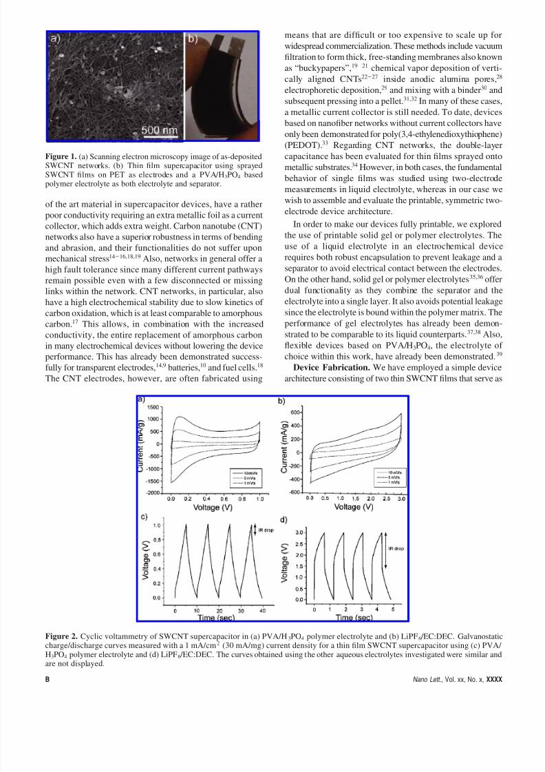
Figure 1. (a) Scanning electron microscopy image of as-depositedSWCNT networks. (b) Thin film supercapacitor using sprayedSWCNT films on PET as electrodes and a PVA/H3PO4 basedpolymer electrolyte as both electrolyte and separator.
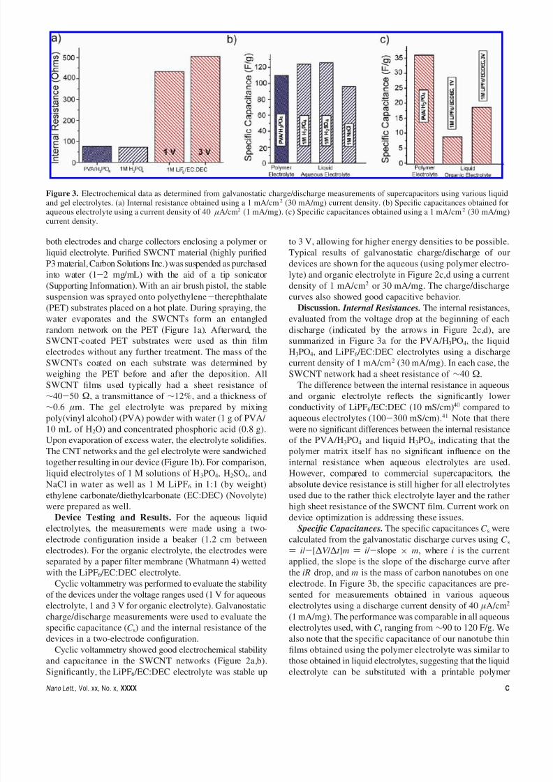
Figure 2. Cyclic voltammetry of SWCNT supercapacitor in (a) PVA/H3PO4 polymer electrolyte and (b) LiPF6 /EC:DEC. Galvanostaticcharge/discharge curves measured with a 1 mA/cm2 (30 mA/mg) current density for a thin film SWCNT supercapacitor using (c) PVA/ H3PO4 polymer electrolyte and (d) LiPF6 /EC:DEC. The curves obtained using the other aqueous electrolytes investigated were similar and
are not displayed.B Nano Lett., Vol. xx, No. x, XXXX
8/17/2019 Printable Thin Film Supercapacitors Using Single-Walled Carbon Nanotubes
http://slidepdf.com/reader/full/printable-thin-film-supercapacitors-using-single-walled-carbon-nanotubes 5/7
both electrodes and charge collectors enclosing a polymer or
liquid electrolyte. Purified SWCNT material (highly purified
P3 material, Carbon Solutions Inc.) was suspended as purchased
into water (1-2 mg/mL) with the aid of a tip sonicator
(Supporting Information). With an air brush pistol, the stable
suspension was sprayed onto polyethylene-therephthalate
(PET) substrates placed on a hot plate. During spraying, the
water evaporates and the SWCNTs form an entangled
random network on the PET (Figure 1a). Afterward, the
SWCNT-coated PET substrates were used as thin film
electrodes without any further treatment. The mass of the
SWCNTs coated on each substrate was determined by
weighing the PET before and after the deposition. All
SWCNT films used typically had a sheet resistance of
∼40-50 Ω, a transmittance of ∼12%, and a thickness of
∼0.6 µm. The gel electrolyte was prepared by mixingpoly(vinyl alcohol) (PVA) powder with water (1 g of PVA/
10 mL of H2O) and concentrated phosphoric acid (0.8 g).
Upon evaporation of excess water, the electrolyte solidifies.
The CNT networks and the gel electrolyte were sandwiched
together resulting in our device (Figure 1b). For comparison,
liquid electrolytes of 1 M solutions of H3PO4, H2SO4, and
NaCl in water as well as 1 M LiPF6 in 1:1 (by weight)
ethylene carbonate/diethylcarbonate (EC:DEC) (Novolyte)
were prepared as well.
Device Testing and Results. For the aqueous liquid
electrolytes, the measurements were made using a two-
electrode configuration inside a beaker (1.2 cm betweenelectrodes). For the organic electrolyte, the electrodes were
separated by a paper filter membrane (Whatmann 4) wetted
with the LiPF6 /EC:DEC electrolyte.
Cyclic voltammetry was performed to evaluate the stability
of the devices under the voltage ranges used (1 V for aqueous
electrolyte, 1 and 3 V for organic electrolyte). Galvanostatic
charge/discharge measurements were used to evaluate the
specific capacitance (C s) and the internal resistance of the
devices in a two-electrode configuration.
Cyclic voltammetry showed good electrochemical stability
and capacitance in the SWCNT networks (Figure 2a,b).
Significantly, the LiPF6 /EC:DEC electrolyte was stable up
to 3 V, allowing for higher energy densities to be possible.
Typical results of galvanostatic charge/discharge of our
devices are shown for the aqueous (using polymer electro-
lyte) and organic electrolyte in Figure 2c,d using a current
density of 1 mA/cm2 or 30 mA/mg. The charge/discharge
curves also showed good capacitive behavior.
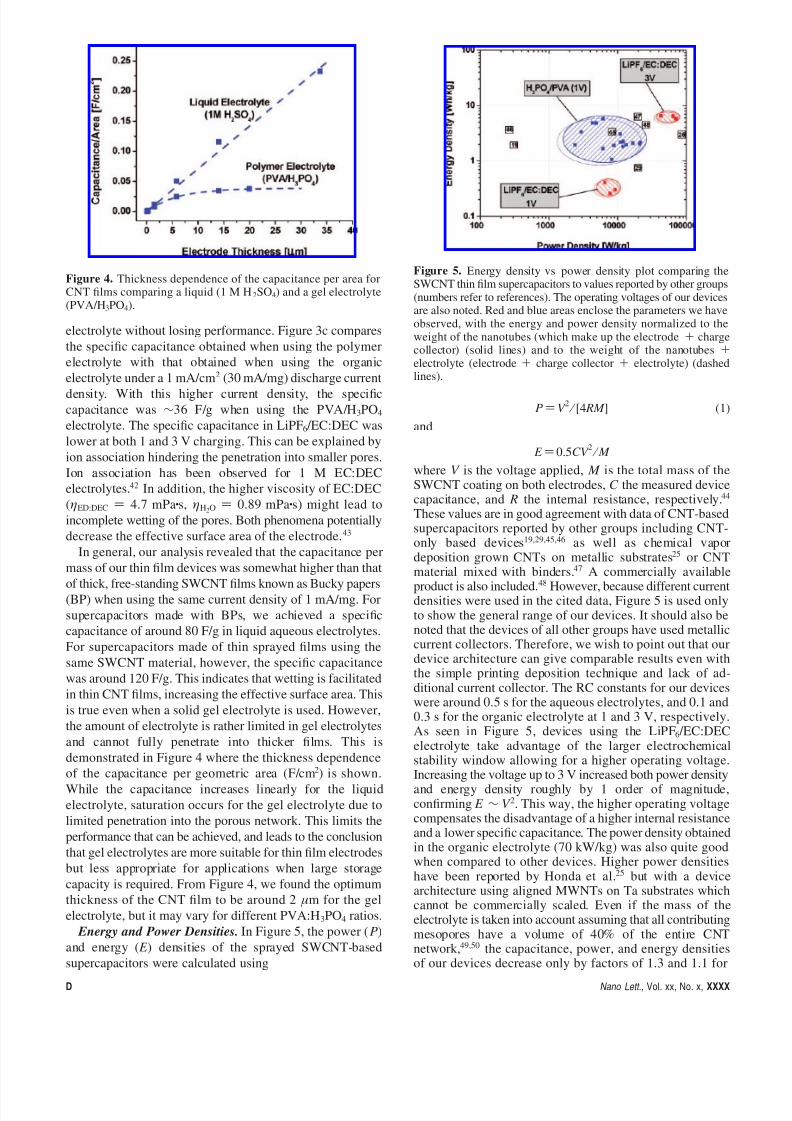
Discussion. Internal Resistances. The internal resistances,
evaluated from the voltage drop at the beginning of each
discharge (indicated by the arrows in Figure 2c,d), are
summarized in Figure 3a for the PVA/H3PO4, the liquid
H3PO4, and LiPF6 /EC:DEC electrolytes using a discharge
current density of 1 mA/cm2 (30 mA/mg). In each case, the
SWCNT network had a sheet resistance of ∼40 Ω.
The difference between the internal resistance in aqueous
and organic electrolyte reflects the significantly lower
conductivity of LiPF6 /EC:DEC (10 mS/cm)40 compared toaqueous electrolytes (100-300 mS/cm).41 Note that there
were no significant differences between the internal resistance
of the PVA/H3PO4 and liquid H3PO4, indicating that the
polymer matrix itself has no significant influence on the
internal resistance when aqueous electrolytes are used.
However, compared to commercial supercapacitors, the
absolute device resistance is still higher for all electrolytes
used due to the rather thick electrolyte layer and the rather
high sheet resistance of the SWCNT film. Current work on
device optimization is addressing these issues.
Specific Capacitances. The specific capacitances C s were
calculated from the galvanostatic discharge curves using C s) i / -[∆V / ∆t ]m ) i / -slope × m, where i is the current
applied, the slope is the slope of the discharge curve after
the iR drop, and m is the mass of carbon nanotubes on one
electrode. In Figure 3b, the specific capacitances are pre-
sented for measurements obtained in various aqueous
electrolytes using a discharge current density of 40 µA/cm2
(1 mA/mg). The performance was comparable in all aqueous
electrolytes used, with C s ranging from ∼90 to 120 F/g. We
also note that the specific capacitance of our nanotube thin
films obtained using the polymer electrolyte was similar to
those obtained in liquid electrolytes, suggesting that the liquid
electrolyte can be substituted with a printable polymer
Figure 3. Electrochemical data as determined from galvanostatic charge/discharge measurements of supercapacitors using various liquidand gel electrolytes. (a) Internal resistance obtained using a 1 mA/cm2 (30 mA/mg) current density. (b) Specific capacitances obtained foraqueous electrolyte using a current density of 40 µA/cm2 (1 mA/mg). (c) Specific capacitances obtained using a 1 mA/cm2 (30 mA/mg)current density.
Nano Lett., Vol. xx, No. x, XXXX C
8/17/2019 Printable Thin Film Supercapacitors Using Single-Walled Carbon Nanotubes
http://slidepdf.com/reader/full/printable-thin-film-supercapacitors-using-single-walled-carbon-nanotubes 6/7
electrolyte without losing performance. Figure 3c compares
the specific capacitance obtained when using the polymer
electrolyte with that obtained when using the organic
electrolyte under a 1 mA/cm2 (30 mA/mg) discharge current
density. With this higher current density, the specific
capacitance was ∼36 F/g when using the PVA/H3PO4
electrolyte. The specific capacitance in LiPF6 /EC:DEC was
lower at both 1 and 3 V charging. This can be explained by
ion association hindering the penetration into smaller pores.
Ion association has been observed for 1 M EC:DEC
electrolytes.42 In addition, the higher viscosity of EC:DEC
(ηED:DEC ) 4.7 mPa·s, ηH2O ) 0.89 mPa·s) might lead to
incomplete wetting of the pores. Both phenomena potentially
decrease the effective surface area of the electrode.43
In general, our analysis revealed that the capacitance per
mass of our thin film devices was somewhat higher than that
of thick, free-standing SWCNT films known as Bucky papers(BP) when using the same current density of 1 mA/mg. For
supercapacitors made with BPs, we achieved a specific
capacitance of around 80 F/g in liquid aqueous electrolytes.
For supercapacitors made of thin sprayed films using the
same SWCNT material, however, the specific capacitance
was around 120 F/g. This indicates that wetting is facilitated
in thin CNT films, increasing the effective surface area. This
is true even when a solid gel electrolyte is used. However,
the amount of electrolyte is rather limited in gel electrolytes
and cannot fully penetrate into thicker films. This is
demonstrated in Figure 4 where the thickness dependence
of the capacitance per geometric area (F/cm2
) is shown.While the capacitance increases linearly for the liquid
electrolyte, saturation occurs for the gel electrolyte due to
limited penetration into the porous network. This limits the
performance that can be achieved, and leads to the conclusion
that gel electrolytes are more suitable for thin film electrodes
but less appropriate for applications when large storage
capacity is required. From Figure 4, we found the optimum
thickness of the CNT film to be around 2 µm for the gel
electrolyte, but it may vary for different PVA:H3PO4 ratios.
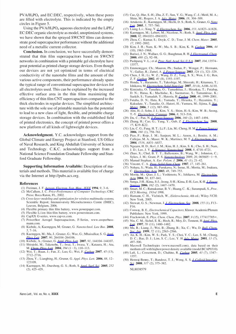
Energy and Power Densities. In Figure 5, the power (P)
and energy ( E ) densities of the sprayed SWCNT-based
supercapacitors were calculated using
P )V 2 ⁄ [4 RM ] (1)
and
E ) 0.5CV 2 ⁄ M
where V is the voltage applied, M is the total mass of theSWCNT coating on both electrodes, C the measured devicecapacitance, and R the internal resistance, respectively.44
These values are in good agreement with data of CNT-basedsupercapacitors reported by other groups including CNT-only based devices19,29,45,46 as well as chemical vapordeposition grown CNTs on metallic substrates25 or CNTmaterial mixed with binders.47 A commercially availableproduct is also included.48 However, because different currentdensities were used in the cited data, Figure 5 is used onlyto show the general range of our devices. It should also benoted that the devices of all other groups have used metalliccurrent collectors. Therefore, we wish to point out that ourdevice architecture can give comparable results even withthe simple printing deposition technique and lack of ad-ditional current collector. The RC constants for our deviceswere around 0.5 s for the aqueous electrolytes, and 0.1 and0.3 s for the organic electrolyte at 1 and 3 V, respectively.As seen in Figure 5, devices using the LiPF6 /EC:DECelectrolyte take advantage of the larger electrochemicalstability window allowing for a higher operating voltage.
Increasing the voltage up to 3 V increased both power densityand energy density roughly by 1 order of magnitude,confirming E ∼ V 2. This way, the higher operating voltagecompensates the disadvantage of a higher internal resistanceand a lower specific capacitance. The power density obtainedin the organic electrolyte (70 kW/kg) was also quite goodwhen compared to other devices. Higher power densitieshave been reported by Honda et al.25 but with a devicearchitecture using aligned MWNTs on Ta substrates whichcannot be commercially scaled. Even if the mass of theelectrolyte is taken into account assuming that all contributingmesopores have a volume of 40% of the entire CNTnetwork,49,50 the capacitance, power, and energy densities
of our devices decrease only by factors of 1.3 and 1.1 for
Figure 4. Thickness dependence of the capacitance per area forCNT films comparing a liquid (1 M H2SO4) and a gel electrolyte(PVA/H3PO4).
Figure 5. Energy density vs power density plot comparing theSWCNT thin film supercapacitors to values reported by other groups(numbers refer to references). The operating voltages of our devicesare also noted. Red and blue areas enclose the parameters we haveobserved, with the energy and power density normalized to theweight of the nanotubes (which make up the electrode + chargecollector) (solid lines) and to the weight of the nanotubes +electrolyte (electrode + charge collector + electrolyte) (dashedlines).
D Nano Lett., Vol. xx, No. x, XXXX
8/17/2019 Printable Thin Film Supercapacitors Using Single-Walled Carbon Nanotubes
http://slidepdf.com/reader/full/printable-thin-film-supercapacitors-using-single-walled-carbon-nanotubes 7/7
PVA/H3PO4 and EC:DEC, respectively, when these poresare filled with electrolyte. This is indicated by the emptycircles in Figure 5.
Using the PVA/H3PO4 aqueous electrolyte and the LiPF6 /
EC:DEC organic electrolyte as model, unoptimized systems,
we have shown that the sprayed SWCNT films can demon-
strate good supercapacitor performance without the additional
need of a metallic current collector.
Conclusion. In conclusion, we have successfully demon-
strated that thin film supercapacitors based on SWCNTnetworks in combination with a printable gel electrolyte have
great potential as printed charge storage devices. Even though
our devices are not yet optimized in terms of electrical
conductivity of the nanotube films and the amount of the
various active components, their performance already spans
the typical range of conventional supercapacitor devices for
all electrolytes used. This can be explained by the increased
effective surface area in the thin films maximizing the
efficiency of thin film CNT supercapacitors compared to the
thick electrodes in regular devices. The simplified architec-
ture with the sole use of printable materials has the potential
to lead to a new class of light, flexible, and printable charge
storage devices. In combination with the established field
of printed electronics, the concept of printed power offers a
new platform of all kinds of lightweight devices.
Acknowledgment. Y.C. acknowledges support from the
Global Climate and Energy Project at Stanford, US Office
of Naval Research, and King Abdullah University of Science
and Technology. C.K.C. acknowledges support from a
National Science Foundation Graduate Fellowship and Stan-
ford Graduate Fellowship.
Supporting Information Available: Description of ma-
terials and methods. This material is available free of charge
via the Internet at http://pubs.acs.org.
References(1) Freiman, J. F. Aerosp. Electron. Syst. Mag., IEEE 1994, 9, 3–6.(2) McCallum, J. C. Price-Performance of Computer Technology; CRC
Press: Boca Raton, FL, 2002.(3) Cross-layer modeling and optimization for wireless multimedia systems,
Scientific Report; Interuniversity Microelectronics Centre (IMEC),Leuven, Belgium, 2006.
(4) Flexible primary thin film battery, www.powerpaper.com.(5) Flexible Li ion thin film battery, www.powerstream.com.(6) CapXX G-series, www.cap-xx.com.(7) PowerStor Aerogel Supercapacitors, F-Series, www.cooperbuss-
mann.com.(8) Kiebele, A; Kaempgen, M; Gruner, G. Nanotechnol. Law Bus. 2008,
5, 7–16.(9) Kaempgen, M.; Ma, J.; Gruner, G.; Wee, G.; Mhaisalkar, S. G. Appl.
Phys. Lett. 2007, 90, 264104–264106.(10) Kiebele, A.; Gruner, G. Appl. Phys. Lett. 2007, 91, 144104–144107.(11) Shiraishi, M.; Takenobu, T.; Iwai, T.; Iwasa, Y.; Kataura, H.; Ata,
M. Chem. Phys. Lett. 2004, 394 (1-3), 110–113.(12) Wei, T.; Ruan, J.; Fan, Z.; Luo, G.; Wei, F. Carbon 2007, 45 (13),
2712–2716.(13) Zhou, Y.; Liangbing, H.; Gruner, G. Appl. Phys. Lett. 2006, 88, 12–
123109.(14) Kaempgen, M.; Duesberg, G. S.; Roth, S. Appl. Surf. Sci. 2005, 252
(2), 425–429.
(15) Cao, Q.; Hur, S.-H.; Zhu, Z.-T.; Sun, Y. G.; Wang, C.-J.; Meitl, M. A.;
Shim, M.; Rogers, J. A. Ad V. Mater. 2006, 18, 304–309.(16) Artukovic, E.; Kaempgen, M.; Hecht, D. S.; Roth, S.; Gruner, G. Nano
Lett. 2005, 5, 757–760.(17) Liang, L.i.; Xing, Y. J. Electrochem. Soc. 2006, 153, A1823–A1828.(18) Kaempgen, M.; Lebert, M.; Nicoloso, N.; Roth, S. Appl. Phys. Lett.
2008, 92, 0941031–0941033.(19) Zhou, C.; Kumar, S.; Doyle, C. D.; Tour, J. M. Chem. Mater. 2005,
17 , 1992–2002.(20) Kim, J. H.; Nam, K.-W.; Ma, S. B.; Kim, K. B. Carbon 2006, 44
(10), 1963–1968.(21) Barisci, J. N.; Wallace, G. G.; Baughman, R. H. J. Electroanal. Chem.
2000, 488 (2), 92–98.(22) Pushparaj, V. L.; et al. Proc. Natl. Acad. Sci. U.S.A. 2007, 104, 13574–
13577.(23) Emmenegger, Ch.; Mauron, Ph.; Sudan, P.; Wenger, P.; Hermann,
V.; Gallay, R.; Zuttel, A. J. Power Sources 2003, 124 (1), 321–329.(24) Chen, J. H.; Li, W. Z.; Wang, D. Z.; Yang, S. X.; Wen, J. G.; Ren,
Z. F. Carbon 2002, 40 (8), 1193–1197.(25) Honda, Y.; Haramoto, T.; Takeshige, M.; Shiozaki, H.; Kitamura, T.;
Ishikawa, M. Electrochem. Solid-State Lett. 2007, 10 (4), A106–A110.(26) Kimizuka, O; Tanaikea, O.; Yamashitaa, J.; Hiraokaa, T.; Futabaa,
D. N.; Hataa, K.; Machidac, K.; Suematsuc, S.; Tamamitsuc, K.;Saekib, S.; Yamadab, Y.; Hatoria, H. Carbon 2008, 46 , 1999–2001.
(27) Futaba, D. N.; Hata, K.; Yamada, T.; Hiraoka, T.; Hayamizu, Y.;Kakudate, Y.; Tanaike, O.; Hatori, H.; Yumura, M.; Iijima, S. Nat.
Mater. 2006, 5 (12), 987–994.(28) Ahn, H.-J.; Sohn, J. I.; Kim, Y. S.; Shim, H.-S.; Kim, W. B.; Seong,
T.-Y. Electrochem. Commun. 2006, 8, 513–516.(29) Du, C.; Pan, N. J. Power Sources 2006, 160 (2), 1487–1494.(30) Zhang, H.; Cao, G.; Yang, Y.; Gub, Z. J. Electrochem. Soc. 2008,
15, K19–K22.(31) Liu, C. G.; Fang, H. T.; Li, F.; Liu, M.; Cheng, H. M. J. Power Sources
2006, 160 (1), 758–761.(32) Pico, F.; Rojo, J. M.; Sanjuan, M. L.; Anson, A.; Benito, A. M.;
Callejas, M. A.; Maser, W. K.; Martinez, M. T. J. Electrochem. Soc.
2004, 1516 , A831–A837.(33) Nguyen, H. D.; Ko1, J. M.; Kim, H. J.; Kim, S. K.; Cho, S. H.; Nam,
J. D.; Lee, J. Y. J. Nanosci. Nanotechnol. 2008, 8 , 4718–4721.(34) Zhao, X.; Chul, B. T. T.; Ballesteros, B.; Wang, W.; Johnston, C.;
Sykes, J. M.; Grant, P. S. Nanotechnology 2009, 20, 065605-1-9.(35) Manuel Stephan, A. Eur. Polym. J. 2006, 41 (1), 21–42.(36) Vincent, C. A. Prog. Solid-State Chem. 1987, 17 , 145–261.(37) Nohara, S.; Wada, H.; Furukawa, N.; Inoue, H.; Morita, M.; Iwakura,
C. Electrochim. Acta 2003, 48, 749–753.(38) Morita, M.; Qiao, J. L.; Yoshimoto, N.; Ishikawa, M. Electrochim.
Acta 2004, 50, 837–841.(39) Sunga, J-H.; Kima, S-J.; Jeong, S-H.; Kima, E-H.; Lee, K-H. J. Power
Sources 2006, 162 (2), 1467–1470.(40) Smart, M. C.; Ratnakumar, B. V.; Huang, C. -K.; Surampudi, S., Proc.
ECS Meeting, 193rd 1998.(41) Hamann, C. H., Vielstich, W., Elektrochemie, 4th ed.; Wiley-VCH:
New York, 2005.(42) Stewart, G. S.; Newman, J. J. Electrochem. Soc. 2008, 155 (1), F13–
F16.(43) Conway, B. E., Electrochemical Capacitors; Kluwer Academic/Plenum
Publishers: New York, 1999.(44) Frackowiak, E. Phys. Chem. Chem. Phys. 2007, 9 (15), 177417785).(45) Niu, C. M.; Sichel, E. K.; Hoch, R.; Moy, D.; Tennent, H. Appl. Phys.
Lett. 1997, 70 (11), 1480–1482.(46) Ma, R.; Liang, J.; Wei, B.; Zhang, B.; Xu, C.; Wu, D. Bull. Chem.
Soc. Jpn. 1999, 72 (11), 2563–2566.(47) An, K. H.; Kim, W. S.; Park, Y. S.; Choi, Y. C.; Lee, S. M.; Chung,
D. C.; Bae, D. J.; Lim, S. C.; Lee, Y. H. Ad V. Mater. 2001, 13 (7),497–500.
(48) Maxwell Technologies (www.maxwell.com), data based on theirmedium cell with highest power density available (model BCAP0310).
(49) Lafi, L.; Cossement, D.; Chahine, R. Carbon 2005, 43 (7), 1347–1357.
(50) Hemraj-Benny, T.; Bandosz, T. J.; Wong, S. S. J. Colloid Interface
Sci. 2008, 317 (2), 375–382.
NL8038579
Nano Lett., Vol. xx, No. x, XXXX E