printed freeform lens arrays on multi-core fibers for
TRANSCRIPT

Printed freeform lens arrays on multi-core fibers for highly efficient coupling in astrophotonic systems PHILIPP-IMMANUEL DIETRICH,1,2,3,6 ROBERT J. HARRIS,4,6 MATTHIAS BLAICHER,1,2 MARK K. CORRIGAN,5 TIM J. MORRIS,5 WOLFGANG FREUDE,2 ANDREAS QUIRRENBACH,4 AND CHRISTIAN KOOS1,2,3,* 1Institute of Microstructure Technology (IMT), Karlsruhe Institute of Technology (KIT), Hermann-von-Helmholtz-Platz 1,76344 Eggenstein-Leopoldshafen, Germany 2Institute of Photonics and Quantum Electronics (IPQ), Karlsruhe Institute of Technology (KIT), Engesserstr. 5, 76131 Karlsruhe, Germany 3Vanguard Photonics GmbH, Hermann-von-Helmholtz-Platz 1,76344 Eggenstein-Leopoldshafen, 76227 Karlsruhe, Germany 4Zentrum für Astronomie der Universität Heidelberg, Landessternwarte Königstuhl, Königstuhl 12, 69117 Heidelberg, Germany 5Durham University, Centre for Advanced Instrumentation, Department of Physics, South Road, Durham, DH1 3LE, UK 6P.-I. D. and R. J. H. contributed equally *[email protected]
Abstract: Coupling of light into multi-core fibers (MCF) for spatially resolved spectroscopy is of great importance to astronomical instrumentation. To achieve high coupling efficiencies along with fill-fractions close to unity, micro-optical elements are required to concentrate the incoming light to the individual cores of the MCF. In this paper we demonstrate facet-attached lens arrays (LA) fabricated by two-photon polymerization. The LA provide close to 100% fill-fraction along with efficiencies of up to 73% (down to 1.4 dB loss) for coupling of light from free space into an MCF core. We show the viability of the concept for astrophotonic applications by integrating an MCF-LA assembly in an adaptive-optics test bed and by assessing its performance as a tip/tilt sensor. © 2017 Optical Society of America OCIS codes: (230.0230) Optical devices; (350.1260) Astronomical optics; (130.0130) Integrated optics; (010.1080) Active or adaptive optics; (300.0300) Spectroscopy.
References and links 1. J. Bland-Hawthorn, J. Lawrence, G. Robertson, S. Campbell, B. Pope, C. Betters, S. Leon-Saval, T. Birks, R.
Haynes, N. Cvetojevic, and N. Jovanovic, “PIMMS: photonic integrated multimode microspectrograph,” Proc. SPIE 7735, 7735ON (2010).
2. A. Bechter, J. Crass, R. Ketterer, J. R. Crepp, R. O. Reynolds, E. Bechter, P. Hinz, F. Pedichini, M. Foley, E. Runburg, and E. Onuma, “On-sky single-mode fiber coupling measurements at the Large Binocular Telescope,” in SPIE Astronomical Telescopes+ Instrumentation (International Society for Optics and Photonics, 2016), paper 99092X.
3. J. Bland-Hawthorn, M. Englund, and G. Edvell, “New approach to atmospheric OH suppression using an aperiodic fibre Bragg grating,” Opt. Express 12(24), 5902–5909 (2004).
4. I. Spaleniak, N. Jovanovic, S. Gross, M. J. Ireland, J. S. Lawrence, and M. J. Withford, “Integrated photonic building blocks for next-generation astronomical instrumentation II: the multimode to single mode transition,” Opt. Express 21(22), 27197–27208 (2013).
5. S. Halverson, A. Roy, S. Mahadevan, and C. Schwab, ““Modal-noise” in single-mode fibers: A cautionary note for high precision radial velocity instruments,” Astrophys. J. 814, 6 (2015).
6. S. Shaklan and F. Roddier, “Coupling starlight into single-mode fiber optics,” Appl. Opt. 27(11), 2334–2338 (1988).
7. S. Esposito, A. Riccardi, E. Pinna, A. Puglisi, F. Quirós-Pacheco, C. Arcidiacono, M. Xompero, R. Briguglio, G. Agapito, L. Busoni, L. Fini, J. Argomedo, A. Gherardi, G. Brusa, D. Miller, J. C. Guerra, P. Stefanini, and P. Salinari, “Large Binocular Telescope Adaptive Optics System: new achievements and perspectives in adaptive
Vol. 25, No. 15 | 24 Jul 2017 | OPTICS EXPRESS 18288
#295277 https://doi.org/10.1364/OE.25.018288 Journal © 2017 Received 4 May 2017; revised 16 Jun 2017; accepted 26 Jun 2017; published 20 Jul 2017
Corrected: 19 September 2017

optics,” in Astronomical Adaptive Optics Systems and Applications IV, R. K. Tyson and M. Hart, eds. (International Society for Optics and Photonics, 2011), paper 814902.
8. N. Jovanovic, C. Schwab, N. Cvetojevic, O. Guyon, and F. Martinache, “Enhancing Stellar Spectroscopy with Extreme Adaptive Optics and Photonics,” Publ. Astron. Soc. Pac. 128(970), 1–15 (2016).
9. M. Glück, J.-U. Pott, and O. Sawodny, “Investigations of an Accelerometer-based Disturbance Feedforward Control for Vibration Suppression in Adaptive Optics of Large Telescopes,” Publ. Astron. Soc. Pac. 129(976), 65001 (2017).
10. P. R. Gillingham, S. Miziarski, and U. Klauser, “Mechanical features of the OzPoz fiber positioner for the VLT,” Proc. SPIE 4008, 914 (2000).
11. J. J. Bryant, J. W. O’Byrne, J. Bland-Hawthorn, and S. G. Leon-Saval, “Characterization of hexabundles: initial results,” Mon. Not. R. Astron. Soc. 415(3), 2173–2181 (2011).
12. P.-I. Dietrich, I. Reuter, M. Blaicher, S. Schneider, M. Billah, T. Hoose, A. Hofmann, C. Caer, R. Dangel, B. Offrein, U. Troppenz, M. Zander, W. Freude, and C. Koos, “Lenses for Low-Loss Chip-to-Fiber and Fiber-to-Fiber Coupling Fabricated by 3D Direct-Write Lithography,” in Conference on Lasers and Electro-Optics (CLEO’16) (OSA, 2016), paper SM1G.4.
13. Zemax, “OpticStudio - Zemax,” http://www.zemax.com/os/opticstudio. 14. Fibercore, “Product - Multicore Fiber,” http://fibercore.com/product/multicore-fiber. 15. Nanoscribe GmbH, “IP Photoresists,” http://www.nanoscribe.de/en/products/ip-photoresists/. 16. R. J. Harris, D. G. MacLachlan, D. Choudhury, T. J. Morris, E. Gendron, A. G. Basden, G. Brown, J. R.
Allington-Smith, and R. R. Thomson, “Photonic spatial reformatting of stellar light for diffraction-limited spectroscopy,” Mon. Not. R. Astron. Soc. 450(1), 428–434 (2015).
17. S. Kirkpatrick, C. D. Gelatt, Jr., and M. P. Vecchi, “Optimization by simulated annealing,” Science 220(4598), 671–680 (1983).
Introduction Optimizing free-space coupling efficiency of light into fibers for spectroscopy is highly important in astronomy due to the low light levels involved. To achieve the required alignment accuracy, the system needs to be very stable. However, this is challenging, as large telescopes are constantly exposed to changing temperatures and gravity vectors. Conventionally, larger multimode fibers are used, relaxing these constraints somewhat. However, with spectrographs aiming for greater precision than ever before, instruments using smaller single-mode fibers (SMF) have been proposed [1,2]. This allows the spectrographs to be reduced in size, and make use of single-mode devices such as fiber Bragg gratings (FBG) for suppression of hydroxyl emission lines [3,4]. Further, a SMF mitigates the problem of modal noise [2,5].
Due to diffraction effects from the telescope aperture, a theoretical maximum of 80% of the incoming light can be coupled into an SMF [6]. However coupling to a SMF is particularly susceptible to the effect of optical turbulence in the atmosphere, which degrades the beam quality and reduces the coupling efficiency to unacceptable levels. To improve this coupling into the fiber, adaptive optics (AO) systems [7] can be used. Further increases in coupling can be achieved using techniques such as point spread function (PSF) apodisation, jitter control [8], linear quadratic Gaussian control (LQG) and feed-forward systems [7].
Together, all of these techniques show that coupling into SM fibers could be viable in future instrumentation. Experiments using turbulence simulators reach 65% [8] coupling, and on-sky experiments show (10…25)% [2]. However, this is still below the optimal coupling, due to remaining residual aberrations and structural vibrations, mainly in the form of tip/tilt [9].
Ideally, any system would sense tip/tilt at the coupling point where the fiber feeds the spectrograph, and would not consume any light that could be fed to the spectrograph. This demand can be realized by highly integrated integral field unit (IFU) devices. An IFU has many spatial pixels (spaxels) sampling the focal plane of the telescope. When connected to a spectrograph, both spatial position and wavelength can be resolved. To use an IFU as a tip/tilt sensor, light from a central spaxel is coupled into the science spectrograph, while adjacent spaxels are used to monitor the position of the beam. Fiber-based IFUs stand out due to their compactness and flexibility. They can be realized with fiber bundles [10], hexabundles [11], or multi-core fibers. The achievable performance, however, is inherently limited by a trade-off of fill-fraction versus cross talk between the fibers.
In this paper we show that the aforementioned challenges can be overcome by lens arrays (LA) that are directly attached to the facet of an MCF. The LA are fabricated in situ by direct-
Vol. 25, No. 15 | 24 Jul 2017 | OPTICS EXPRESS 18289

write two-photon lithography with sub-µm precision. We demonstrate fill-fractions of close to 100% along with efficiencies of up to 73% (1.4 dB loss) for coupling of light from free space into a single-mode MCF core. We show that this IFU-style device can be used as a tip/tilt sensor for measuring the beam displacement at the facet of a single-mode MCF. The surrounding fiber cores supply a feedback signal for correction of residual tip/tilt movement in the system. We demonstrate the viability of our MCF-LA in an adaptive optics simulator. To the best of our knowledge, this is the first demonstration of MCFs with lenses attached to individual fiber cores.
1. Concept, Design, and Fabrication The concept of the facet-attached LA is illustrated in Fig. 1(a). It comprises seven 3D freeform lenses fabricated with sub-µm precision on the facet of a seven-core single-mode MCF. The assembly aims at maximizing coupling efficiency of the main signal into the center core, whereas the surrounding cores are used to capture error signals for tip/tilt control. For better illustration of main path and error signal, the lens array and part of the fiber are cut away in the illustration. The Inset shows the simulated coupling efficiency to the center core and one adjacent core as a function of radial offset from the center assuming a Gaussian beam with a waist of 26 µm in diameter on the top surface of the lenses. Figure 1(b) shows the 3D topography of the lens array measured with a white-light interferometer. An electron microscope image of a fabricated LA is shown in Fig. 1(c). The concept builds upon earlier experiments where we used direct-write two-photon lithography to realize facet-attached lenses for improved fiber-chip coupling [12].
1.1 Simulation and Design
The tip/tilt sensor was simulated with the physical-optics module of the commercially available software Zemax [13]. We used a commercially available seven-core fiber [14] with a 1/e2-intensity mode-field diameter (MFD) of 0 6. µm2 1 w = . The data sheet specified a numerical aperture of 0.22 at a wavelength of 1550 nm, derived from the beam divergence at the 1/102 = 1 % intensity level. The numerical aperture for a Gaussian beam at the 1/e2-intensity level would be AN0 = 2λ/(2πw0) = 0.16. The core spacing is 35 µm, and the fiber diameter is 125 µm, see Fig. 1(a). This means that cross coupling between the cores can be neglected. The lens surfaces were modelled by even polynomials with coefficients up to the sixth order. We optimized the coefficients of the polynomials for maximum coupling of a beam with a 26 µm Gaussian waist at the surface of a single freeform lens into the fiber core. The diameter of the simulated lens was chosen to be 40 µm such that there is a 5 µm overlap between adjacent lenses to achieve a 100% fill-fraction. The height of the lenses was designed to be 115 µm. The highest simulated coupling efficiency excluding reflection was 98.5%. We found that 1% loss can be attributed to clipping of the beam, while 0.5% loss is due to a residual mode-field mismatch. We simulated the coupling efficiency of a single lens with respect to a transverse misalignment of the Gaussian waist, see inset Fig. 1(a). The 1 dB (79%) tolerance is ± 7.2 µm, assuming a freeform lens with a 35 µm diameter. We additionally simulate the light coupled into an adjacent fiber core. This signal can be considered a feedback-signal that is fed into an adaptive optics system. With a 1 dB position tolerance (79%) of the center core, the error signal is found to be at 1.6% of the maximum coupling efficiency.
Vol. 25, No. 15 | 24 Jul 2017 | OPTICS EXPRESS 18290

Fig. 1. 3D freeform lens array fabricated on the facet of a multi-core fiber (MCF). The center core use to capture the main signal for spectral analysis, whereas the adjacent cores are used to measure error signals for tip/tilt correction. Mechanical dimensions and mode-field diameters (MFDs) are indicated in µm. (a) 3D model of the MCF and the fabricated lens array. For better illustration of beam path (red) and error signal (orange), the lens array and part of the fiber are cut away. Inset: Simulated and measured coupling efficiency of the main signal and of the error signal. Note that, due to the available lenses and for avoiding an iris diaphragm, the MFD of the measured signal was only 21 µm instead of the optimum 26 µm; this explains the discrepancy between simulation and measurement. (b) 3D topography of the lens array measured with a white-light interferometer. The maximum distance d of the lens surfaces from the MCF facet are indicated. (c) Electron microscopy image at a 45° angle of the lens array in situ printed on the MCF facet. The fiber has a diameter of 125 µm.
1.2 Fabrication by 3D printing
We used two-photon polymerization of the commercial resist IP-Dip [15] for in situ printing of the freeform lenses on the facet of a cleaved MCF. The structures were defined by a commercial device (Nanoscribe Photonic ProfessionalGT) with proprietary software for high-precision alignment and writing with high shape fidelity. The system was equipped with a scanning mirror and a piezo actuator. We exposed the structure by line-scanning with a 100 nm spacing of adjacent exposure lines. The lens array shown in Fig. 1(a) was fabricated in a single block.
Vol. 25, No. 15 | 24 Jul 2017 | OPTICS EXPRESS 18291

Alignment of the individual lenses with respect to the cores was done using machine vision and confocal scanning. A scanning electron microscopy image (SEM) of a fabricated lens array is shown in Fig. 1(b). A vertically-scanned white-light interferometry image (VSI) is shown in Fig. 1(c). The height of the lenses was measured from the facet of the SMF. All lenses are within ± 500 nm of the designed height of 115 µm, well within acceptable tolerances.
2. Characterization and measurement of coupling efficiency To evaluate the performance of the MCF-LA, the coupling efficiency from a free-space Gaussian beam to the central core was measured. The measurement was performed using a fiber-attached beam expander (Thorlabs TC25FC-1550, MFD = 4.65 mm) with a diffraction-limited focusing lens (Thorlabs AL2550H, f = 50 mm) to produce a Gaussian waist diameter of 21 µm, which is slightly smaller than the 26 µm MFD the lenses were designed for. Note that we did not use an iris diaphragm which would have lead to an Airy-type intensity distribution and hence to increased coupling loss. As a reference, we coupled the test focal field into an integrating sphere – the same devices that is subsequently used to measure the power coupled captured by the MCF cores. The extra Fresnel reflection loss of 0.16 dB from the plane MCF end was taken into account. The coupling efficiency of the test focal field into the fiber amounted to 73% (1.4 dB loss). The coupling loss can be partly attributed to Fresnel reflection at the freeform lens (4%, 0.2 dB) and partly to the mode-field mismatch of the test focus with 21 µm instead of the 26 µm used for the design (2%, 0.1 dB). The residual coupling loss of (21%, 1.1 dB) can be attributed to the imperfectly cleaved facet that leads to a slightly angled fabrication of the freeform-lens array. Simulation indicates that a tilt of 3° of the MCF facet normal with respect to the optical axis of the MCF leads to a coupling loss of 1 dB, which approximately corresponds to the measured loss. This can be avoided by a better cleaving procedure or by polished fiber facets as in fiber-arrays or physical-contact (PC) fiber connectors. To confirm the simulation of the position dependency of the signal coupled into the MCF, see Section 1.1, we show the position-resolved coupling efficiency in the inset of Fig. 1(a). To avoid coupling of light into several fiber cores, we couple light into one of the outer cores and show the signal decay when moving the test focus away from the center core. We find fair agreement to the simulated data. The observed deviations are a consequence of the reduced MFD of 21 µm instead of the optimum 26 µm.
3. Demonstration as a tip/tilt sensor 3.1 Adaptive optics testbed
In order to assess the potential of the MCF-LA as a tip/tilt sensor, the sensitivity to beam displacement was tested. This was performed using an adaptive optics testbed configured in a similar way to that described in [16], see Fig. 2. The system is fed by two fibers. The first is a multimode fiber, coupled to a 633 nm laser for wavefront sensing by a Shack-Hartmann sensor. The second beam is emitted by a single-mode fiber (SMF) which carries light from a 1550 nm laser and is used to simulate the light of an AO system. Both fiber outputs are collimated and pass through an iris diaphragm located at the pupil plane of the beam expander. To allow the deformable mirror (DM) to have the correct spacing from the iris, the beam is re-collimated by two lenses with longer focal lengths. The light is reflected from a beamsplitter onto the DM. This allows to control tip, tilt and other low-order aberrations. At a dichroic mirror, the 663nm light is reflected to a Shack-Hartman sensor to monitor the shape of the DM. We thereby obtain a feedback signal that allows us to control the DM. The 1550 nm light is transmitted to the test section, where a beam splitter and a lens direct 10% of the light onto an infrared (IR) camera (Xenics-Xeva 1.7 320 InGaAs) while 90% of the light is focused to the surface of the 3D printed lenses.
Vol. 25, No. 15 | 24 Jul 2017 | OPTICS EXPRESS 18292

Fig. 2. Schematic of the beam path used for testing the lens array attached to the multi-core fiber (MCF). The common input beam is shown in red (1550 nm from a single mode fiber, SMF) and blue (633 nm from a multimode fiber, MMF). The 633nm beam is used for feedback control of the deformable mirror while the 1550nm beam is focused onto the MCF lens-array (MCF-LA). The beam position is scanned using the deformable mirror that is operated with an optical feedback from the Shack-Hartmann sensor. The amount of light coupled into individual fiber cores of the MCF can be obtained by observing the rear facet of the MCF with an infrared (IR) camera. To monitor the beam quality, a reference beam (yellow) is split off from the main beam (red).
3.2 Use as a tip/tilt sensor
The MCF-LA was placed in the adaptive optics testbed, see Section 3.1. A simulated-annealing algorithm was performed [17] to initially adjust the DM for optimum coupling, and the DM was then used to scan the beam waist (see Fig. 2) across the 3D-printed lenses in order to ascertain the response. To this end, we imaged the end facet of the fiber with the infrared (IR) camera and calculated the optical power in each individual core. This power output is shown in Fig. 3 as a function of the test focus position. The position of the individual plots corresponds to the measured fiber core at the output facet. All plots are normalized to the maximum coupling of the central core. The color-coded intensities show that, as expected, the coupling is maximum when the beam waist is positioned at the center of the corresponding micro-lens. For example, the coupling for the central fiber is best when the beam waist is centered on this fiber. All the lenses show similar responses, with only minor deviations for the outer ones, which we attribute due to loss of image quality as the position of the test beam is scanned away from the axis of the center lens and to inaccuracies in the positioning of the deformable mirror. For application as a tip/tilt sensor, the center fiber can be connected to a spectrometer, while the other lenses generate a beam displacement-dependent error signal that can be used to compensate residual tip/tilt of the beam.
Vol. 25, No. 15 | 24 Jul 2017 | OPTICS EXPRESS 18293
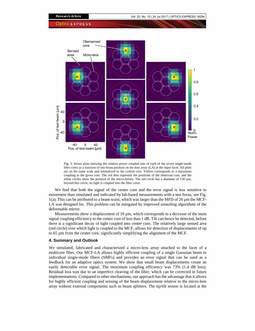
Fig. 3. Seven plots showing the relative power coupled into of each of the seven single-mode fiber cores as a function of test beam position on the lens array (LA) at the input facet. All plots are on the same scale and normalized to the central core. Yellow corresponds to a maximum coupling to the given core. The red dots represent the positions of the observed core, and the white circles show the position of the micro-lenses. The red circle has a diameter of 130 µm, beyond this circle, no light is coupled into the fiber cores.
We find that both the signal of the center core and the error signal is less sensitive to movement than simulated and indicated by lab-based measurements with a test focus, see Fig. 1(a). This can be attributed to a beam waist, which was larger than the MFD of 26 µm the MCF-LA was designed for. This problem can be mitigated by improved annealing algorithms of the deformable mirror.
Measurements show a displacement of 10 µm, which corresponds to a decrease of the main signal coupling efficiency to the center core of less than 1 dB. Tilt can hence be detected, before there is a significant decay of light coupled into center core. The relatively large sensed area (red circle) over which light is coupled to the MCF, allows for detection of displacements of up to 65 µm from the center core, significantly simplifying the alignment of the MCF.
4. Summary and Outlook We simulated, fabricated and characterized a micro-lens array attached to the facet of a multicore fiber. Our MCF-LA allows highly efficient coupling of a single Gaussian beam to individual single-mode fibers (SMFs) and provides an error signal that can be used as a feedback for an adaptive optics system. We show that small beam displacements create an easily detectable error signal. The maximum coupling efficiency was 73% (1.4 dB loss). Residual loss was due to an imperfect cleaving of the fiber, which can be corrected in future implementations. Compared to other mechanisms, our approach has the advantage that it allows for highly efficient coupling and sensing of the beam displacement relative to the micro-lens array without external components such as beam splitters. The tip/tilt sensor is located at the
Vol. 25, No. 15 | 24 Jul 2017 | OPTICS EXPRESS 18294

position of the coupling device itself, and non-common path aberrations or vibrations between sensing and coupling device can be avoided. Our MCF-LA can sense a beam displacement of up to 65 µm. By connecting our MCF to a commercially available MCF-to-SMF fan-out [14], high speed detectors with SMF pigtails can be used.
Our demonstration also paves the path to innovative multichannel optical devices such as a new generation of integral field units (IFUs) with 100% fill-fraction and high coupling efficiency. Facet-attached lens arrays are not limited to coupling to single-mode devices. Using a suitable multimode multicore fiber, the concept could be used for devices similar to hexabundles [11]. Our next effort will concentrate on improvements of coupling efficiency, flexibility and ruggedness of the system in order to allow deployment as part of an astronomical instrument. To achieve this, we print lens arrays on standard commercial mountings, e.g., on a fiber coupling ferrule. This increases the flexibility and ruggedness of the system and allows an easy integration in an astronomical instrument. In addition, fabrication on a standard polished ferrule will automatically resolve issues with imperfectly cleaved fiber facets.
Funding This work was supported by the BMBF Project PHOIBOS (Grant 13N12574); by the Helmholtz International Research School for Teratronics (HIRST); by the European Research Council (ERC Starting Grant 280145 ‘EnTeraPIC’); by the EU-FP7 project BigPipes; by the H2020 Photonic Packaging Pilot Line PIXAPP; by the Alfried Krupp von Bohlen und Halbach Foundation; by the Karlsruhe Nano-Micro Facility (KNMF); by the Deutsche Forschungsgemeinschaft (DFG) through SFB 1173; by the IBM PhD Fellowship Program (P.-I. D.); and by the Carl-Zeiss-Foundation (R.H.).
Acknowledgments We thank Marco Hummel and Lutz Geuer for fabricating mechanical setups, and Florian Rupp for recording SEM images.
Vol. 25, No. 15 | 24 Jul 2017 | OPTICS EXPRESS 18295