prism experiment
DESCRIPTION
Prism PDFTRANSCRIPT

Contents
1 Spectrometer 11.1 Optical spectrometer . . . . . . . . . . . . . . . . . . . . . . . . . . . . . . . . . . . . . . . . . 11.2 Mass spectrometer . . . . . . . . . . . . . . . . . . . . . . . . . . . . . . . . . . . . . . . . . . . 11.3 Time-of-flight spectrometer . . . . . . . . . . . . . . . . . . . . . . . . . . . . . . . . . . . . . . 11.4 Magnetic spectrometer . . . . . . . . . . . . . . . . . . . . . . . . . . . . . . . . . . . . . . . . 11.5 Resolution . . . . . . . . . . . . . . . . . . . . . . . . . . . . . . . . . . . . . . . . . . . . . . . 21.6 References . . . . . . . . . . . . . . . . . . . . . . . . . . . . . . . . . . . . . . . . . . . . . . 2
2 Prism 32.1 How prisms work . . . . . . . . . . . . . . . . . . . . . . . . . . . . . . . . . . . . . . . . . . . 3
2.1.1 Deviation angle and dispersion . . . . . . . . . . . . . . . . . . . . . . . . . . . . . . . . 42.2 Prisms and the nature of light . . . . . . . . . . . . . . . . . . . . . . . . . . . . . . . . . . . . . 42.3 Types of prisms . . . . . . . . . . . . . . . . . . . . . . . . . . . . . . . . . . . . . . . . . . . . 5
2.3.1 Dispersive prisms . . . . . . . . . . . . . . . . . . . . . . . . . . . . . . . . . . . . . . . 52.3.2 Reflective prisms . . . . . . . . . . . . . . . . . . . . . . . . . . . . . . . . . . . . . . . 52.3.3 Polarizing prisms . . . . . . . . . . . . . . . . . . . . . . . . . . . . . . . . . . . . . . . 52.3.4 Deflecting prisms . . . . . . . . . . . . . . . . . . . . . . . . . . . . . . . . . . . . . . . 6
2.4 In optometry . . . . . . . . . . . . . . . . . . . . . . . . . . . . . . . . . . . . . . . . . . . . . . 62.5 See also . . . . . . . . . . . . . . . . . . . . . . . . . . . . . . . . . . . . . . . . . . . . . . . . 62.6 References . . . . . . . . . . . . . . . . . . . . . . . . . . . . . . . . . . . . . . . . . . . . . . . 62.7 Further reading . . . . . . . . . . . . . . . . . . . . . . . . . . . . . . . . . . . . . . . . . . . . 62.8 External links . . . . . . . . . . . . . . . . . . . . . . . . . . . . . . . . . . . . . . . . . . . . . 6
3 Minimum deviation 73.1 References . . . . . . . . . . . . . . . . . . . . . . . . . . . . . . . . . . . . . . . . . . . . . . . 7
4 Angle of incidence 84.1 Optics . . . . . . . . . . . . . . . . . . . . . . . . . . . . . . . . . . . . . . . . . . . . . . . . . 8
4.1.1 Grazing angle . . . . . . . . . . . . . . . . . . . . . . . . . . . . . . . . . . . . . . . . . 84.2 Angle of incidence of fixed-wing aircraft . . . . . . . . . . . . . . . . . . . . . . . . . . . . . . . 84.3 See also . . . . . . . . . . . . . . . . . . . . . . . . . . . . . . . . . . . . . . . . . . . . . . . . 94.4 Notes . . . . . . . . . . . . . . . . . . . . . . . . . . . . . . . . . . . . . . . . . . . . . . . . . 94.5 External links . . . . . . . . . . . . . . . . . . . . . . . . . . . . . . . . . . . . . . . . . . . . . 9
i
ii CONTENTS
5 Refractive index 105.1 Definition . . . . . . . . . . . . . . . . . . . . . . . . . . . . . . . . . . . . . . . . . . . . . . . 105.2 History . . . . . . . . . . . . . . . . . . . . . . . . . . . . . . . . . . . . . . . . . . . . . . . . . 115.3 Typical values . . . . . . . . . . . . . . . . . . . . . . . . . . . . . . . . . . . . . . . . . . . . . 11
5.3.1 Refractive index below unity . . . . . . . . . . . . . . . . . . . . . . . . . . . . . . . . . 115.3.2 Negative refractive index . . . . . . . . . . . . . . . . . . . . . . . . . . . . . . . . . . . 12
5.4 Microscopic explanation . . . . . . . . . . . . . . . . . . . . . . . . . . . . . . . . . . . . . . . . 125.5 Dispersion . . . . . . . . . . . . . . . . . . . . . . . . . . . . . . . . . . . . . . . . . . . . . . . 125.6 Complex refractive index . . . . . . . . . . . . . . . . . . . . . . . . . . . . . . . . . . . . . . . 135.7 Relations to other quantities . . . . . . . . . . . . . . . . . . . . . . . . . . . . . . . . . . . . . . 14
5.7.1 Optical path length . . . . . . . . . . . . . . . . . . . . . . . . . . . . . . . . . . . . . . 145.7.2 Refraction . . . . . . . . . . . . . . . . . . . . . . . . . . . . . . . . . . . . . . . . . . . 155.7.3 Total internal reflection . . . . . . . . . . . . . . . . . . . . . . . . . . . . . . . . . . . . 155.7.4 Reflectivity . . . . . . . . . . . . . . . . . . . . . . . . . . . . . . . . . . . . . . . . . . 155.7.5 Lenses . . . . . . . . . . . . . . . . . . . . . . . . . . . . . . . . . . . . . . . . . . . . . 155.7.6 Microscope resolution . . . . . . . . . . . . . . . . . . . . . . . . . . . . . . . . . . . . . 165.7.7 Relative permittivity and permeability . . . . . . . . . . . . . . . . . . . . . . . . . . . . 165.7.8 Density . . . . . . . . . . . . . . . . . . . . . . . . . . . . . . . . . . . . . . . . . . . . 165.7.9 Group index . . . . . . . . . . . . . . . . . . . . . . . . . . . . . . . . . . . . . . . . . . 175.7.10 Momentum (Abraham–Minkowski controversy) . . . . . . . . . . . . . . . . . . . . . . . 175.7.11 Other relations . . . . . . . . . . . . . . . . . . . . . . . . . . . . . . . . . . . . . . . . 175.7.12 Refractivity . . . . . . . . . . . . . . . . . . . . . . . . . . . . . . . . . . . . . . . . . . 17
5.8 Nonscalar, nonlinear, or nonhomogeneous refraction . . . . . . . . . . . . . . . . . . . . . . . . . 175.8.1 Birefringence . . . . . . . . . . . . . . . . . . . . . . . . . . . . . . . . . . . . . . . . . 175.8.2 Nonlinearity . . . . . . . . . . . . . . . . . . . . . . . . . . . . . . . . . . . . . . . . . . 185.8.3 Inhomogeneity . . . . . . . . . . . . . . . . . . . . . . . . . . . . . . . . . . . . . . . . 18
5.9 Refractive index measurement . . . . . . . . . . . . . . . . . . . . . . . . . . . . . . . . . . . . . 185.9.1 Homogeneous media . . . . . . . . . . . . . . . . . . . . . . . . . . . . . . . . . . . . . 195.9.2 Refractive index variations . . . . . . . . . . . . . . . . . . . . . . . . . . . . . . . . . . 19
5.10 Applications . . . . . . . . . . . . . . . . . . . . . . . . . . . . . . . . . . . . . . . . . . . . . . 205.11 See also . . . . . . . . . . . . . . . . . . . . . . . . . . . . . . . . . . . . . . . . . . . . . . . . 205.12 References . . . . . . . . . . . . . . . . . . . . . . . . . . . . . . . . . . . . . . . . . . . . . . . 205.13 External links . . . . . . . . . . . . . . . . . . . . . . . . . . . . . . . . . . . . . . . . . . . . . 22
6 Prism spectrometer 236.1 Theory . . . . . . . . . . . . . . . . . . . . . . . . . . . . . . . . . . . . . . . . . . . . . . . . . 236.2 Usage . . . . . . . . . . . . . . . . . . . . . . . . . . . . . . . . . . . . . . . . . . . . . . . . . 23
6.2.1 Spectroscopy . . . . . . . . . . . . . . . . . . . . . . . . . . . . . . . . . . . . . . . . . 236.2.2 Measurement of refractive index . . . . . . . . . . . . . . . . . . . . . . . . . . . . . . . 23
6.3 External links . . . . . . . . . . . . . . . . . . . . . . . . . . . . . . . . . . . . . . . . . . . . . 246.4 Text and image sources, contributors, and licenses . . . . . . . . . . . . . . . . . . . . . . . . . . 25
6.4.1 Text . . . . . . . . . . . . . . . . . . . . . . . . . . . . . . . . . . . . . . . . . . . . . . 25
CONTENTS iii
6.4.2 Images . . . . . . . . . . . . . . . . . . . . . . . . . . . . . . . . . . . . . . . . . . . . 266.4.3 Content license . . . . . . . . . . . . . . . . . . . . . . . . . . . . . . . . . . . . . . . . 27
Chapter 1
Spectrometer
In physics, a spectrometer is an apparatus to measure aspectrum.[1] Generally, a spectrum is a graph that showsintensity as a function of wavelength, of frequency, ofenergy, of momentum, or of mass.
1.1 Optical spectrometer
Optical spectrometers (often simply called “spectrome-ters”), in particular, show the intensity of light as a func-tion of wavelength or of frequency. The deflection is pro-duced either by refraction in a prism or by diffraction ina diffraction grating.
1.2 Mass spectrometer
A mass spectrometer is an analytical instrument that isused to identify the amount and type of chemicals presentin a sample by measuring the mass-to-charge ratio andabundance of gas-phase ions.[2]
1.3 Time-of-flight spectrometer
The energy spectrum of particles of known mass can alsobe measured by determining the time of flight betweentwo detectors (and hence, the velocity) in a time-of-flightspectrometer. Alternatively, if the velocity is known,masses can be determined in a time-of-flight mass spec-trometer.
1.4 Magnetic spectrometer
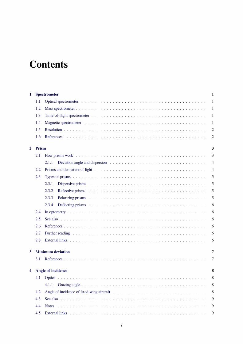
When a fast charged particle (charge q, mass m) entersa constant magnetic field B at right angles, it is deflectedinto a circular path of radius r, due to the Lorentz force.The momentum p of the particle is then given by
p = mv = qBr
B
v
+F
A positive charged particle moving in a circle under the influenceof the Lorentz force F
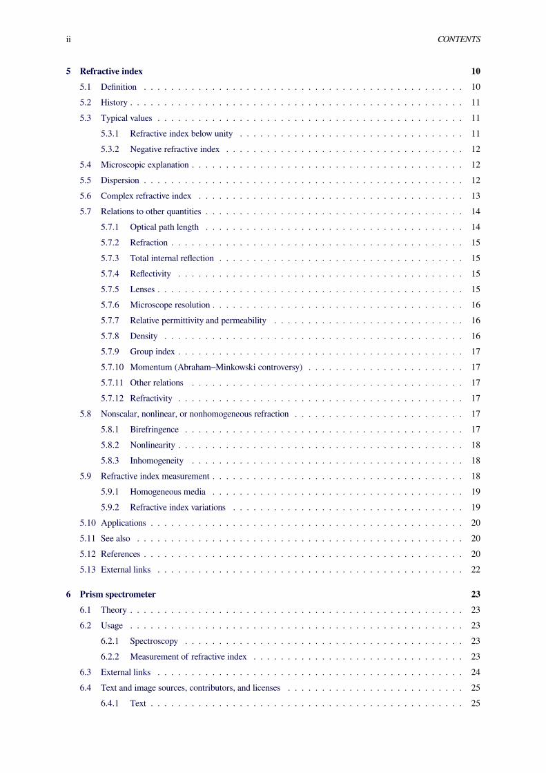
Focus of a magnetic semicircular spectrometer
where m and v are mass and velocity of the particle. Thefocussing principle of the oldest and simplest magneticspectrometer, the semicircular spectrometer,[3] inventedby J. K. Danisz, is shown on the left. A constant magneticfield is perpendicular to the page. Charged particles ofmomentum p that pass the slit are deflected into circularpaths of radius r = p/qB. Evidently, they hit the horizontalline at nearly the same place, the focus, where a particlecounter should be placed. Varying B, this makes possi-ble to measure the energy spectrum of alpha particles inan alpha particle spectrometer, of beta particles in a betaparticle spectrometer,[1] of particles (e.g., fast ions) in aparticle spectrometer, or to measure the relative contentof the various masses in a mass spectrometer.
1
2 CHAPTER 1. SPECTROMETER
Since Danysz' time, many types of magnetic spectrom-eters more complicated than the semicircular type havebeen devised.[1]
1.5 Resolution
Generally, the resolution of an instrument tells us howwell two close-lying energies (or wavelengths, or frequen-cies, or masses) can be resolved. Generally, for an instru-ment with mechanical slits, higher resolution will meanlower intensity.[1]
1.6 References[1] K. Siegbahn, Alpha-, Beta- and Gamma-Ray Spec-
troscopy, North-Holland Publishing Co. Amsterdam(1966)
[2] “mass spectrometer” (PDF). 2009.doi:10.1351/goldbook.M03732.
[3] Jan Kazimierz Danysz, Le Radium 9, 1 (1912); 10, 4(1913)
Chapter 2
Prism
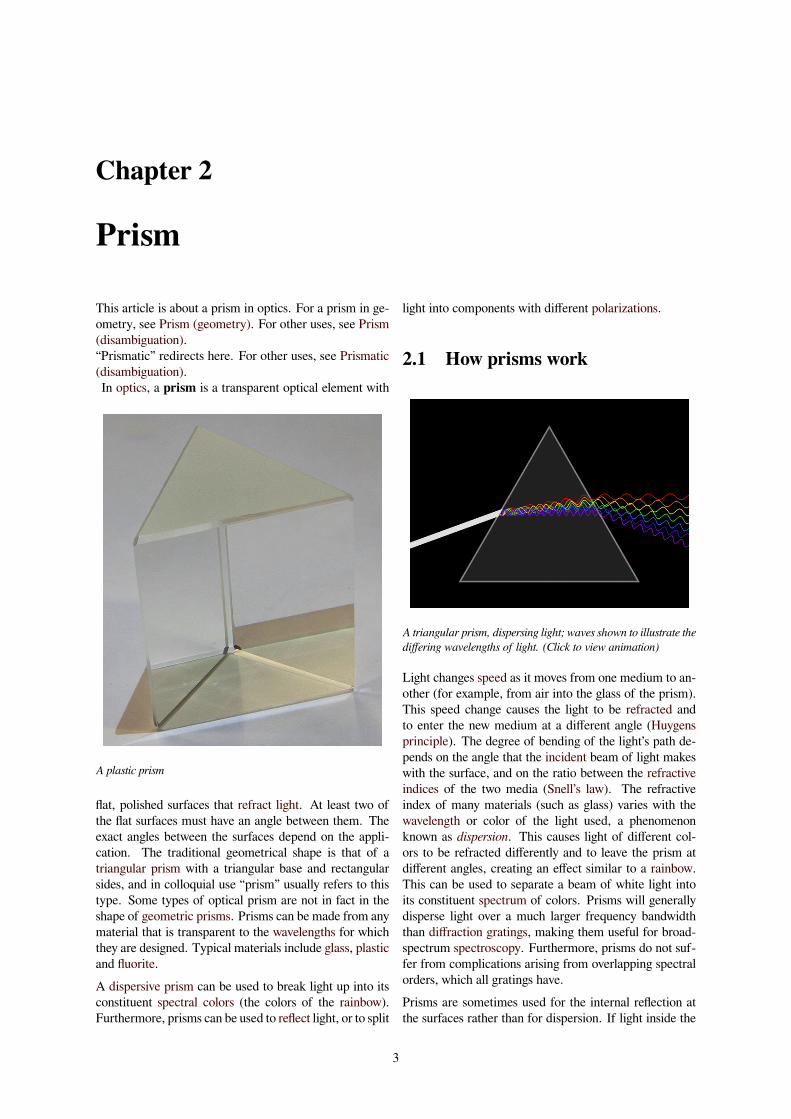
This article is about a prism in optics. For a prism in ge-ometry, see Prism (geometry). For other uses, see Prism(disambiguation).“Prismatic” redirects here. For other uses, see Prismatic(disambiguation).In optics, a prism is a transparent optical element with
A plastic prism
flat, polished surfaces that refract light. At least two ofthe flat surfaces must have an angle between them. Theexact angles between the surfaces depend on the appli-cation. The traditional geometrical shape is that of atriangular prism with a triangular base and rectangularsides, and in colloquial use “prism” usually refers to thistype. Some types of optical prism are not in fact in theshape of geometric prisms. Prisms can be made from anymaterial that is transparent to the wavelengths for whichthey are designed. Typical materials include glass, plasticand fluorite.A dispersive prism can be used to break light up into itsconstituent spectral colors (the colors of the rainbow).Furthermore, prisms can be used to reflect light, or to split
light into components with different polarizations.
2.1 How prisms work
A triangular prism, dispersing light; waves shown to illustrate thediffering wavelengths of light. (Click to view animation)
Light changes speed as it moves from one medium to an-other (for example, from air into the glass of the prism).This speed change causes the light to be refracted andto enter the new medium at a different angle (Huygensprinciple). The degree of bending of the light’s path de-pends on the angle that the incident beam of light makeswith the surface, and on the ratio between the refractiveindices of the two media (Snell’s law). The refractiveindex of many materials (such as glass) varies with thewavelength or color of the light used, a phenomenonknown as dispersion. This causes light of different col-ors to be refracted differently and to leave the prism atdifferent angles, creating an effect similar to a rainbow.This can be used to separate a beam of white light intoits constituent spectrum of colors. Prisms will generallydisperse light over a much larger frequency bandwidththan diffraction gratings, making them useful for broad-spectrum spectroscopy. Furthermore, prisms do not suf-fer from complications arising from overlapping spectralorders, which all gratings have.Prisms are sometimes used for the internal reflection atthe surfaces rather than for dispersion. If light inside the
3
4 CHAPTER 2. PRISM
prism hits one of the surfaces at a sufficiently steep an-gle, total internal reflection occurs and all of the light isreflected. This makes a prism a useful substitute for amirror in some situations.
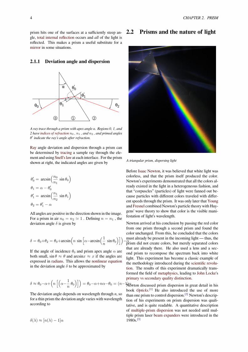
2.1.1 Deviation angle and dispersion
2
θ
α
0 2θ
10
0θʹ
1θʹ
1θ
A ray trace through a prism with apex angle α. Regions 0, 1, and2 have indices of refraction n0 , n1 , and n2 , and primed anglesθ′ indicate the ray’s angle after refraction.
Ray angle deviation and dispersion through a prism canbe determined by tracing a sample ray through the ele-ment and using Snell’s law at each interface. For the prismshown at right, the indicated angles are given by
θ′0 = arcsin(n0
n1sin θ0
)θ1 = α− θ′0
θ′1 = arcsin(n1
n2sin θ1
)θ2 = θ′1 − α
All angles are positive in the direction shown in the image.For a prism in air n0 = n2 ≃ 1 . Defining n = n1 , thedeviation angle δ is given by
δ = θ0+θ2 = θ0+arcsin(n sin
[α−arcsin
( 1
nsin θ0
)])−α
If the angle of incidence θ0 and prism apex angle α areboth small, sin θ ≈ θ and arcsinx ≈ x if the angles areexpressed in radians. This allows the nonlinear equationin the deviation angle δ to be approximated by
δ ≈ θ0−α+(n[(
α− 1
nθ0
)])= θ0−α+nα−θ0 = (n−1)α .
The deviation angle depends on wavelength through n, sofor a thin prism the deviation angle varies with wavelengthaccording to
δ(λ) ≈ [n(λ)− 1]α
2.2 Prisms and the nature of light
A triangular prism, dispersing light
Before Isaac Newton, it was believed that white light wascolorless, and that the prism itself produced the color.Newton’s experiments demonstrated that all the colors al-ready existed in the light in a heterogeneous fashion, andthat “corpuscles” (particles) of light were fanned out be-cause particles with different colors traveled with differ-ent speeds through the prism. It was only later that Youngand Fresnel combinedNewton’s particle theory with Huy-gens’ wave theory to show that color is the visible mani-festation of light’s wavelength.Newton arrived at his conclusion by passing the red colorfrom one prism through a second prism and found thecolor unchanged. From this, he concluded that the colorsmust already be present in the incoming light — thus, theprism did not create colors, but merely separated colorsthat are already there. He also used a lens and a sec-ond prism to recompose the spectrum back into whitelight. This experiment has become a classic example ofthe methodology introduced during the scientific revolu-tion. The results of this experiment dramatically trans-formed the field of metaphysics, leading to John Locke'sprimary vs secondary quality distinction.Newton discussed prism dispersion in great detail in hisbook Opticks.[1] He also introduced the use of morethan one prism to control dispersion.[2] Newton’s descrip-tion of his experiments on prism dispersion was quali-tative, and is quite readable. A quantitative descriptionof multiple-prism dispersion was not needed until mul-tiple prism laser beam expanders were introduced in the1980s.[3]
2.3. TYPES OF PRISMS 5
2.3 Types of prisms
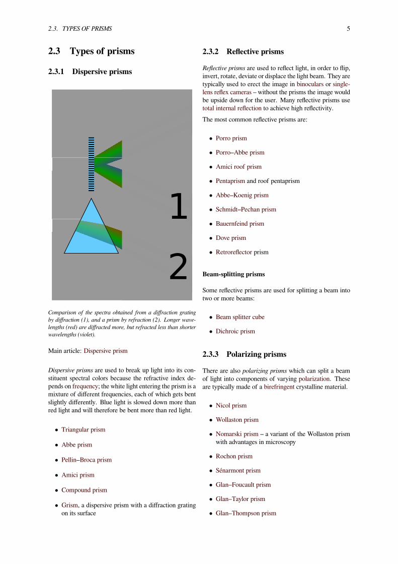
2.3.1 Dispersive prisms
1
2Comparison of the spectra obtained from a diffraction gratingby diffraction (1), and a prism by refraction (2). Longer wave-lengths (red) are diffracted more, but refracted less than shorterwavelengths (violet).
Main article: Dispersive prism
Dispersive prisms are used to break up light into its con-stituent spectral colors because the refractive index de-pends on frequency; the white light entering the prism is amixture of different frequencies, each of which gets bentslightly differently. Blue light is slowed down more thanred light and will therefore be bent more than red light.
• Triangular prism
• Abbe prism
• Pellin–Broca prism
• Amici prism
• Compound prism
• Grism, a dispersive prism with a diffraction gratingon its surface
2.3.2 Reflective prisms
Reflective prisms are used to reflect light, in order to flip,invert, rotate, deviate or displace the light beam. They aretypically used to erect the image in binoculars or single-lens reflex cameras – without the prisms the image wouldbe upside down for the user. Many reflective prisms usetotal internal reflection to achieve high reflectivity.The most common reflective prisms are:
• Porro prism
• Porro–Abbe prism
• Amici roof prism
• Pentaprism and roof pentaprism
• Abbe–Koenig prism
• Schmidt–Pechan prism
• Bauernfeind prism
• Dove prism
• Retroreflector prism
Beam-splitting prisms
Some reflective prisms are used for splitting a beam intotwo or more beams:
• Beam splitter cube
• Dichroic prism
2.3.3 Polarizing prisms
There are also polarizing prisms which can split a beamof light into components of varying polarization. Theseare typically made of a birefringent crystalline material.
• Nicol prism
• Wollaston prism
• Nomarski prism – a variant of the Wollaston prismwith advantages in microscopy
• Rochon prism
• Sénarmont prism
• Glan–Foucault prism
• Glan–Taylor prism
• Glan–Thompson prism
6 CHAPTER 2. PRISM
2.3.4 Deflecting prisms
Wedge prisms are used to deflect a beam of light by a fixedangle. A pair of such prisms can be used for beam steer-ing; by rotating the prisms the beam can be deflected intoany desired angle within a conical “field of regard”. Themost commonly found implementation is a Risley prismpair.[4] Two wedge prisms can also be used as an anamor-phic pair to change the shape of a beam. This is used tomake a round beam from the elliptical output of a laserdiode.Rhomboid prisms are used to laterally displace a beam oflight without inverting the image.Deck prisms were used on sailing ships to bring daylightbelow deck, since candles and kerosene lamps are a firehazard on wooden ships.
2.4 In optometry
By shifting corrective lenses off axis, images seen throughthem can be displaced in the same way that a prism dis-places images. Eye care professionals use prisms, as wellas lenses off axis, to treat various orthoptics problems:
• Diplopia (double vision)• Positive and negative fusion problems• Positive relative accommodation and negative rela-tive accommodation problems.
Prism spectacles with a single prism perform a relativedisplacement of the two eyes, thereby correcting eso-,exo, hyper- or hypotropia.In contrast, spectacles with prisms of equal power forboth eyes, called yoked prisms (also: conjugate prisms,ambient lenses or performance glasses) shift the visualfield of both eyes to the same extent.[5]
2.5 See also• Minimum deviation• Multiple-prism dispersion theory• Prism compressor• Prism dioptre• Prism spectrometer• Prism (geometry)• Theory of Colours• Triangular prism (geometry)• Superprism• Eyeglass prescription
2.6 References[1] I. Newton (1704). Opticks. London: Royal Society. ISBN
0-486-60205-2.
[2] “The Discovery of the Spectrum of Light”. Retrieved 19December 2009.
[3] F. J. Duarte and J. A. Piper (1982). “Dispersiontheory of multiple-prism beam expanders for pulseddye lasers”. Opt. Commun. 43 (5): 303–307. Bibcode:1982OptCo..43..303D. doi:10.1016/0030-4018(82)90216-4.
[4] B.D. Duncan; et al. (2003). “Wide-angle achro-matic prism beam steering for infrared coun-termeasure applications”. Opt. Eng. 42 (4):1038–1047. Bibcode:2003OptEn..42.1038D.doi:10.1117/1.1556393.
[5] Kaplan, M; Carmody, D. P.; Gaydos, A (1996). “Posturalorientation modifications in autism in response to ambientlenses”. Child Psychiatry and Human Development 27 (2):81–91. PMID 8936794.
2.7 Further reading• Hecht, Eugene (2001). Optics (4th ed.). PearsonEducation. ISBN 0-8053-8566-5.
2.8 External links• Java applet of refraction through a prism
Chapter 3
Minimum deviation
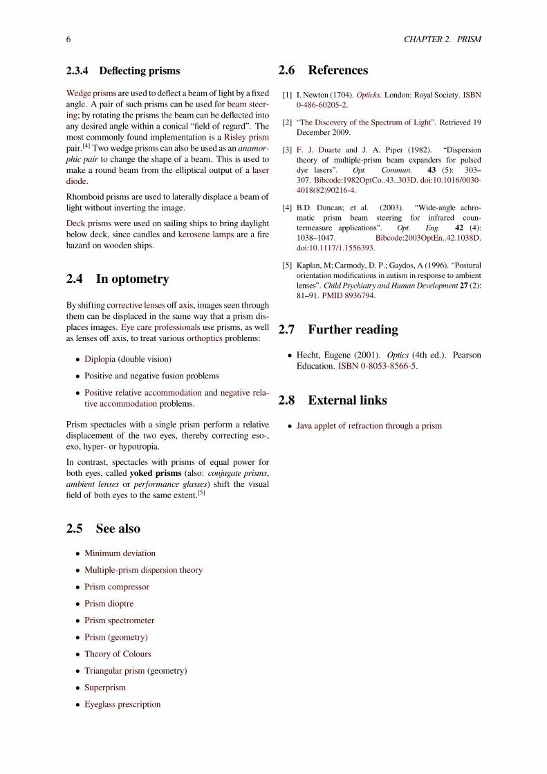
Light is deflected as it enters a material with refractive index > 1.
A ray of light is deflected twice in a prism. The sum of thesedeflections is the deviation angle.
When the entrance and exit angles are equal, the deviation angleof a ray passing through a prism will be a minimum.
As a ray of light enters a transparent material, the ray’sdirection is deflected, based on both the entrance angle(typically measured relative to the perpendicular to thesurface) and thematerial’s refractive index, and accordingto Snell’s Law. A beam passing through an object like a
prism or water drop is deflected twice: once entering, andagain when exiting. The sum of these two deflections iscalled the deviation angle.The deviation angle in a prism depends upon:Refractive index of the prism: The refractive index de-pends on thematerial and the wavelength of the light. Thelarger the refractive index, the larger the deviation angle.Angle of the prism: The larger the prism angle, thelarger the deviation angle.Angle of incidence: The deviation angle depends on theangle that the beam enters the object, called angle of inci-dence. The deviation angle first decreases with increasingincidence angle, and then it increases.There is an angle of incidence at which the sum of thetwo deflections is a minimum. The deviation angle at thispoint is called the “minimum deviation” angle, or “angleof minimum deviation”.[1] At the minimum deviation an-gle, the incidence and exit angles of the ray are identical.This is a consequence of the principle of time reversibil-ity; if the incidence and exit angles were not identical,then reversing the paths (exit becomes entrance, and viceversa) would indicate erroneously that there were two in-cidence angles resulting in minimum deviation. One ofthe factors that causes a rainbow is the bunching of lightrays at the minimum deviation angle that is close to therainbow angle.A convenient way to measure the refractive index of aprism is to direct a light ray through the prism so it pro-duces the minimum deviation angle. This yields a simpleformula:[2]
nλ =sin(A+Dλ
2 )
sin(A2 )
where n is the refractive index at a wavelength λ , D is theangle of minimum deviation, and A is the internal angleof the prism.
3.1 References[1] Mark A. Peterson. “Minimum Deviation by a Prism”.
Mount Holyoke College.
[2] “Derivation of Angle of Deviation through a Prism”.
7
Chapter 4
Angle of incidence
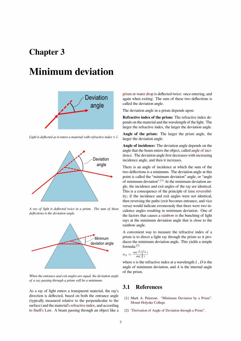
Angle of incidence
Angle of incidence is a measure of deviation of some-thing from “straight on”, for example:
• in the approach of a ray to a surface, or
• the angle at which the wing or horizontal tail of anairplane is installed on the fuselage, measured rela-tive to the axis of the fuselage.
4.1 Optics
In geometric optics, the angle of incidence is the anglebetween a ray incident on a surface and the line perpen-dicular to the surface at the point of incidence, called thenormal. The ray can be formed by any wave: optical,acoustic, microwave, X-ray and so on. In the figure above,the red line representing a ray makes an angle θ with thenormal (dotted line). The angle of incidence at whichlight is first totally internally reflected is known as thecritical angle. The angle of reflection and angle of re-fraction are other angles related to beams.Determining the angle of reflection with respect to a pla-nar surface is trivial, but the computation for almost anyother surface is significantly more difficult. The exact so-lution for a sphere (which has important applications inastronomy and computer graphics) was an open problem
for nearly 50 years until a closed-form result was derivedby mathematicians Allen R Miller and Emanuel Vegh in1991.[1]
Air
Water
n1
n2
Critical angle
Refra
cted
ray
θ1θ1
θ2
θ2
θc
Total internalreflection
Inci
dent
ray
Refraction of light at the interface between two media.
4.1.1 Grazing angle
When dealing with a beam that is nearly parallel to a sur-face, it is sometimes more useful to refer to the angle be-tween the beam and the surface, rather than that betweenthe beam and the surface normal, in other words 90° mi-nus the angle of incidence. This small angle is called aglancing angle or grazing angle. Incidence at grazingangles is called “grazing incidence”.Grazing incidence diffraction is used in X-ray spec-troscopy and atom optics, where significant reflection canbe achieved only at small values of the grazing angle.Ridged mirrors are designed for reflection of atoms com-ing at small grazing angle. This angle is usually measuredin milliradians. In optics, there is Lloyd’s mirror.
4.2 Angle of incidence of fixed-wing aircraft
On fixed-wing aircraft, the angle of incidence (sometimesreferred to as the mounting angle[2]) is the angle betweenthe chord line of the wing where the wing is mounted tothe fuselage, and a reference axis along the fuselage (oftenthe direction of minimum drag, or where applicable, thelongitudinal axis). The angle of incidence is fixed in thedesign of the aircraft, and with rare exceptions, cannot bevaried in flight.The term can also be applied to horizontal surfaces in gen-eral (such as canards or horizontal stabilizers) for the an-
8
4.5. EXTERNAL LINKS 9
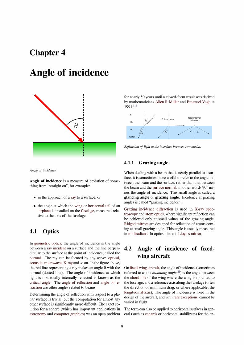
Angle of incidence of an airplane wing on an airplane.
gle they make relative the longitudinal axis of the fuse-lage.The figure to the right shows a side view of an airplane.The extended chord line of the wing root (red line) makesan angle with the longitudinal axis (roll axis) of the air-craft (blue line). Wings are typically mounted at a smallpositive angle of incidence, to allow the fuselage to behave a low angle with the airflow in cruising flight. An-gles of incidence of about 6° are common onmost generalaviation designs. Other terms for angle of incidence inthis context are rigging angle and rigger’s angle of inci-dence. It should not be confused with the angle of attack,which is the angle the wing chord presents to the airflowin flight. Note that some ambiguity in this terminologyexists, as some engineering texts that focus solely on thestudy of airfoils and their medium may use either termwhen referring to angle of attack. The use of the term“angle of incidence” to refer to the angle of attack occurschiefly in British usage.[3]
4.3 See also
• Effect of sun angle on climate
• Reflection (physics)
• Refraction
• Season
• Total internal reflection
4.4 Notes
[1] Allen R Miller and Emanuel Vegh (1993). “Ex-act Result for the Grazing Angle of Specular Reflec-tion from a Sphere”. SIAM Review 35: 472–480.doi:10.1137/1035091.
[2] Phillips, Warren F. (2010). Mechanics of Flight (2nd ed.).Wiley & Sons. ISBN 978-0-470-53975-0.
[3] Kermode, A.C. (1972), Mechanics of Flight, Chapter 3,8th edition, Pitman Publishing, London. ISBN 0-273-31623-0
4.5 External links• Weisstein, Eric W., “Angle of incidence”,MathWorld.
• geometry : rebound on the strip billiards Flash ani-mation
Chapter 5
Refractive index
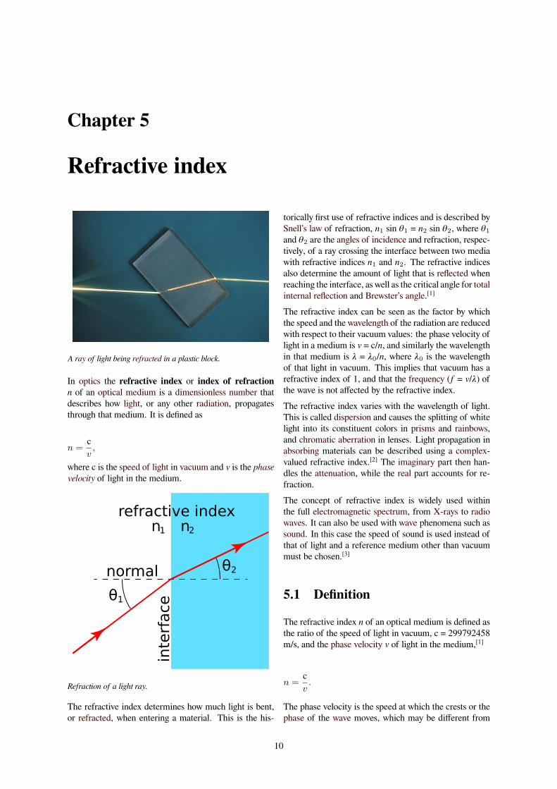
A ray of light being refracted in a plastic block.
In optics the refractive index or index of refractionn of an optical medium is a dimensionless number thatdescribes how light, or any other radiation, propagatesthrough that medium. It is defined as
n =cv,
where c is the speed of light in vacuum and v is the phasevelocity of light in the medium.
refractive indexn1 n2
θ1
θ2normal
inte
rface
Refraction of a light ray.
The refractive index determines how much light is bent,or refracted, when entering a material. This is the his-
torically first use of refractive indices and is described bySnell’s law of refraction, n1 sin θ1 = n2 sin θ2, where θ1and θ2 are the angles of incidence and refraction, respec-tively, of a ray crossing the interface between two mediawith refractive indices n1 and n2. The refractive indicesalso determine the amount of light that is reflected whenreaching the interface, as well as the critical angle for totalinternal reflection and Brewster’s angle.[1]
The refractive index can be seen as the factor by whichthe speed and the wavelength of the radiation are reducedwith respect to their vacuum values: the phase velocity oflight in a medium is v = c/n, and similarly the wavelengthin that medium is λ = λ0/n, where λ0 is the wavelengthof that light in vacuum. This implies that vacuum has arefractive index of 1, and that the frequency (f = v/λ) ofthe wave is not affected by the refractive index.The refractive index varies with the wavelength of light.This is called dispersion and causes the splitting of whitelight into its constituent colors in prisms and rainbows,and chromatic aberration in lenses. Light propagation inabsorbing materials can be described using a complex-valued refractive index.[2] The imaginary part then han-dles the attenuation, while the real part accounts for re-fraction.The concept of refractive index is widely used withinthe full electromagnetic spectrum, from X-rays to radiowaves. It can also be used with wave phenomena such assound. In this case the speed of sound is used instead ofthat of light and a reference medium other than vacuummust be chosen.[3]
5.1 Definition
The refractive index n of an optical medium is defined asthe ratio of the speed of light in vacuum, c = 299792458m/s, and the phase velocity v of light in the medium,[1]
n =cv.
The phase velocity is the speed at which the crests or thephase of the wave moves, which may be different from
10
5.3. TYPICAL VALUES 11
the group velocity, the speed at which the pulse of lightor the envelope of the wave moves.The definition above is sometimes referred to as theabsolute refractive index or the absolute index ofrefraction to distinguish it from definitions where thespeed of light in other reference media than vacuum isused.[1] Historically air at a standardized pressure andtemperature have been common as a reference medium.
5.2 History
Thomas Young coined the term index of refraction.
Thomas Young was presumably the person who first used,and invented, the name “index of refraction”, in 1807.[4]At the same time he changed this value of refractivepower into a single number, instead of the traditional ra-tio of two numbers. The ratio had the disadvantage ofdifferent appearances. Newton, who called it the “pro-portion of the sines of incidence and refraction”, wrote itas a ratio of two numbers, like “529 to 396” (or “nearly4 to 3"; for water).[5] Hauksbee, who called it the “ratioof refraction”, wrote it as a ratio with a fixed numerator,like “10000 to 7451.9” (for urine).[6] Hutton wrote it as aratio with a fixed denominator, like 1.3358 to 1 (water).[7]
Young did not use a symbol for the index of refraction,in 1807. In the next years, others started using differ-ent symbols: n, m, and µ.[8][9][10] The symbol n graduallyprevailed.
5.3 Typical values
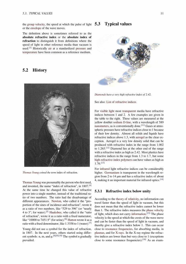
Diamonds have a very high refractive index of 2.42.
See also: List of refractive indices
For visible light most transparent media have refractiveindices between 1 and 2. A few examples are given inthe table to the right. These values are measured at theyellow doublet sodium D-line, with a wavelength of 589nanometers, as is conventionally done.[11] Gases at atmo-spheric pressure have refractive indices close to 1 becauseof their low density. Almost all solids and liquids haverefractive indices above 1.3, with aerogel as the clear ex-ception. Aerogel is a very low density solid that can beproduced with refractive index in the range from 1.002to 1.265.[12] Diamond lies at the other end of the rangewith a refractive index as high as 2.42. Most plastics haverefractive indices in the range from 1.3 to 1.7, but somehigh-refractive-index polymers can have values as high as1.76.[13]
For infrared light refractive indices can be considerablyhigher. Germanium is transparent in the wavelength re-gion from 2 to 14 µm and has a refractive index of about4, making it an important material for infrared optics.[14]
5.3.1 Refractive index below unity
According to the theory of relativity, no information cantravel faster than the speed of light in vacuum, but thisdoes not mean that the refractive index cannot be lowerthan 1. The refractive index measures the phase velocityof light, which does not carry information.[15] The phasevelocity is the speed at which the crests of the wave moveand can be faster than the speed of light in vacuum, andthereby give a refractive index below 1. This can occurclose to resonance frequencies, for absorbing media, inplasmas, and for X-rays. In the X-ray regime the refrac-tive indices are lower than but very close to 1 (exceptionsclose to some resonance frequencies).[16] As an exam-
12 CHAPTER 5. REFRACTIVE INDEX
ple, water has a refractive index of 0.99999974 = 1 −2.6×10⁻⁷ for X-ray radiation at a photon energy of 30keV (0.04 nm wavelength).[16]
5.3.2 Negative refractive index
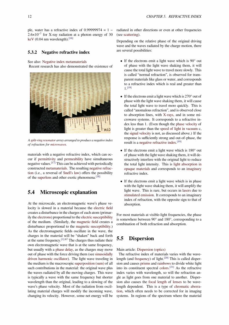
See also: Negative index metamaterialsRecent research has also demonstrated the existence of
A split-ring resonator array arranged to produce a negative indexof refraction for microwaves.
materials with a negative refractive index, which can oc-cur if permittivity and permeability have simultaneousnegative values.[17] This can be achieved with periodicallyconstructed metamaterials. The resulting negative refrac-tion (i.e., a reversal of Snell’s law) offers the possibilityof the superlens and other exotic phenomena.[18]
5.4 Microscopic explanation
At the microscale, an electromagnetic wave’s phase ve-locity is slowed in a material because the electric fieldcreates a disturbance in the charges of each atom (primar-ily the electrons) proportional to the electric susceptibilityof the medium. (Similarly, the magnetic field creates adisturbance proportional to the magnetic susceptibility.)As the electromagnetic fields oscillate in the wave, thecharges in the material will be “shaken” back and forthat the same frequency.[1]:67 The charges thus radiate theirown electromagnetic wave that is at the same frequency,but usually with a phase delay, as the charges may moveout of phase with the force driving them (see sinusoidallydriven harmonic oscillator). The light wave traveling inthe medium is the macroscopic superposition (sum) of allsuch contributions in the material: the original wave plusthe waves radiated by all the moving charges. This waveis typically a wave with the same frequency but shorterwavelength than the original, leading to a slowing of thewave’s phase velocity. Most of the radiation from oscil-lating material charges will modify the incoming wave,changing its velocity. However, some net energy will be
radiated in other directions or even at other frequencies(see scattering).Depending on the relative phase of the original drivingwave and the waves radiated by the charge motion, thereare several possibilities:
• If the electrons emit a light wave which is 90° outof phase with the light wave shaking them, it willcause the total light wave to travel more slowly. Thisis called “normal refraction”, is observed for trans-parent materials like glass or water, and correspondsto a refractive index which is real and greater than1.[19]
• If the electrons emit a light wavewhich is 270° out ofphase with the light wave shaking them, it will causethe total light wave to travel more quickly. This iscalled “anomalous refraction”, and is observed closeto absorption lines, with X-rays, and in some mi-crowave systems. It corresponds to a refractive in-dex less than 1. (Even though the phase velocity oflight is greater than the speed of light in vacuum c,the signal velocity is not, as discussed above.) If theresponse is sufficiently strong and out-of-phase, theresult is a negative refractive index.[19]
• If the electrons emit a light wave which is 180° outof phase with the light wave shaking them, it will de-structively interfere with the original light to reducethe total light intensity. This is light absorption inopaque materials and corresponds to an imaginaryrefractive index.
• If the electrons emit a light wave which is in phasewith the light wave shaking them, it will amplify thelight wave. This is rare, but occurs in lasers due tostimulated emission. It corresponds to an imaginaryindex of refraction, with the opposite sign to that ofabsorption.
For most materials at visible-light frequencies, the phaseis somewhere between 90° and 180°, corresponding to acombination of both refraction and absorption.
5.5 Dispersion
Main article: Dispersion (optics)The refractive index of materials varies with the wave-
length (and frequency) of light.[20] This is called disper-sion and causes prisms and rainbows to divide white lightinto its constituent spectral colors.[21] As the refractiveindex varies with wavelength, so will the refraction an-gle as light goes from one material to another. Disper-sion also causes the focal length of lenses to be wave-length dependent. This is a type of chromatic aberra-tion, which often needs to be corrected for in imagingsystems. In regions of the spectrum where the material
5.6. COMPLEX REFRACTIVE INDEX 13
Light of different colors has slightly different refractive indicesin water and therefore shows up at different positions in therainbow.
In a prism dispersion causes different colors to refract at differentangles, splitting white light into a rainbow of colors.
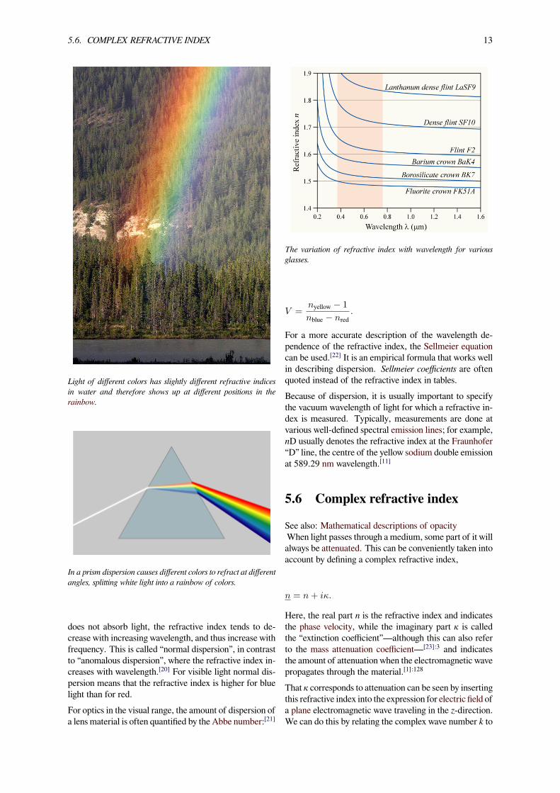
does not absorb light, the refractive index tends to de-crease with increasing wavelength, and thus increase withfrequency. This is called “normal dispersion”, in contrastto “anomalous dispersion”, where the refractive index in-creases with wavelength.[20] For visible light normal dis-persion means that the refractive index is higher for bluelight than for red.For optics in the visual range, the amount of dispersion ofa lens material is often quantified by the Abbe number:[21]
The variation of refractive index with wavelength for variousglasses.
V =nyellow − 1
nblue − nred.
For a more accurate description of the wavelength de-pendence of the refractive index, the Sellmeier equationcan be used.[22] It is an empirical formula that works wellin describing dispersion. Sellmeier coefficients are oftenquoted instead of the refractive index in tables.Because of dispersion, it is usually important to specifythe vacuum wavelength of light for which a refractive in-dex is measured. Typically, measurements are done atvarious well-defined spectral emission lines; for example,nD usually denotes the refractive index at the Fraunhofer“D” line, the centre of the yellow sodium double emissionat 589.29 nm wavelength.[11]
5.6 Complex refractive index
See also: Mathematical descriptions of opacityWhen light passes through a medium, some part of it willalways be attenuated. This can be conveniently taken intoaccount by defining a complex refractive index,
n = n+ iκ.
Here, the real part n is the refractive index and indicatesthe phase velocity, while the imaginary part κ is calledthe “extinction coefficient”—although this can also referto the mass attenuation coefficient—[23]:3 and indicatesthe amount of attenuation when the electromagnetic wavepropagates through the material.[1]:128
That κ corresponds to attenuation can be seen by insertingthis refractive index into the expression for electric field ofa plane electromagnetic wave traveling in the z-direction.We can do this by relating the complex wave number k to
14 CHAPTER 5. REFRACTIVE INDEX
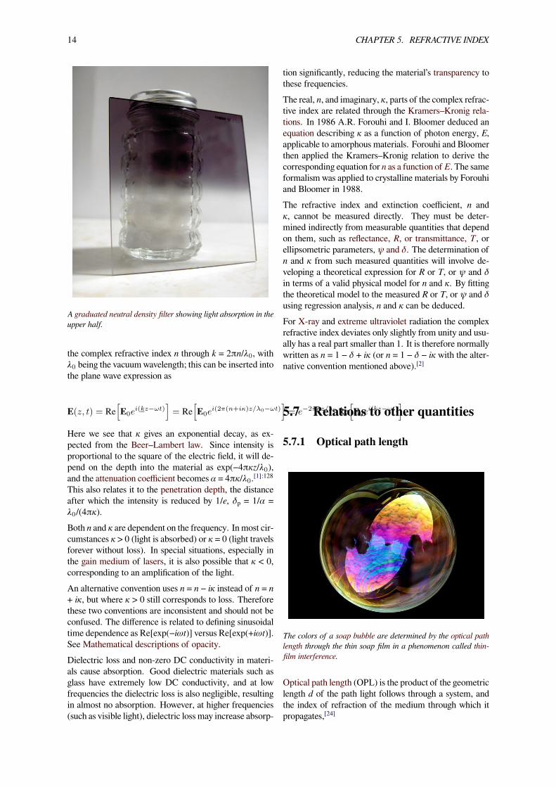
A graduated neutral density filter showing light absorption in theupper half.
the complex refractive index n through k = 2πn/λ0, withλ0 being the vacuum wavelength; this can be inserted intothe plane wave expression as
E(z, t) = Re[E0e
i(kz−ωt)]= Re
[E0e
i(2π(n+iκ)z/λ0−ωt)]= e−2πκz/λ0 Re
[E0e
i(kz−ωt)].
Here we see that κ gives an exponential decay, as ex-pected from the Beer–Lambert law. Since intensity isproportional to the square of the electric field, it will de-pend on the depth into the material as exp(−4πκz/λ0),and the attenuation coefficient becomes α = 4πκ/λ0.[1]:128This also relates it to the penetration depth, the distanceafter which the intensity is reduced by 1/e, δ = 1/α =λ0/(4πκ).Both n and κ are dependent on the frequency. In most cir-cumstances κ > 0 (light is absorbed) or κ = 0 (light travelsforever without loss). In special situations, especially inthe gain medium of lasers, it is also possible that κ < 0,corresponding to an amplification of the light.An alternative convention uses n = n − iκ instead of n = n+ iκ, but where κ > 0 still corresponds to loss. Thereforethese two conventions are inconsistent and should not beconfused. The difference is related to defining sinusoidaltime dependence as Re[exp(−iωt)] versus Re[exp(+iωt)].See Mathematical descriptions of opacity.Dielectric loss and non-zero DC conductivity in materi-als cause absorption. Good dielectric materials such asglass have extremely low DC conductivity, and at lowfrequencies the dielectric loss is also negligible, resultingin almost no absorption. However, at higher frequencies(such as visible light), dielectric loss may increase absorp-
tion significantly, reducing the material’s transparency tothese frequencies.The real, n, and imaginary, κ, parts of the complex refrac-tive index are related through the Kramers–Kronig rela-tions. In 1986 A.R. Forouhi and I. Bloomer deduced anequation describing κ as a function of photon energy, E,applicable to amorphous materials. Forouhi and Bloomerthen applied the Kramers–Kronig relation to derive thecorresponding equation for n as a function of E. The sameformalism was applied to crystalline materials by Forouhiand Bloomer in 1988.The refractive index and extinction coefficient, n andκ, cannot be measured directly. They must be deter-mined indirectly from measurable quantities that dependon them, such as reflectance, R, or transmittance, T , orellipsometric parameters, ψ and δ. The determination ofn and κ from such measured quantities will involve de-veloping a theoretical expression for R or T, or ψ and δin terms of a valid physical model for n and κ. By fittingthe theoretical model to the measured R or T, or ψ and δusing regression analysis, n and κ can be deduced.For X-ray and extreme ultraviolet radiation the complexrefractive index deviates only slightly from unity and usu-ally has a real part smaller than 1. It is therefore normallywritten as n = 1 − δ + iκ (or n = 1 − δ − iκ with the alter-native convention mentioned above).[2]
5.7 Relations to other quantities
5.7.1 Optical path length
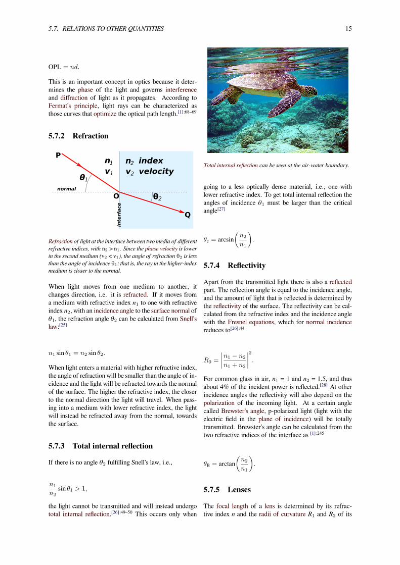
The colors of a soap bubble are determined by the optical pathlength through the thin soap film in a phenomenon called thin-film interference.
Optical path length (OPL) is the product of the geometriclength d of the path light follows through a system, andthe index of refraction of the medium through which itpropagates,[24]
5.7. RELATIONS TO OTHER QUANTITIES 15
OPL = nd.
This is an important concept in optics because it deter-mines the phase of the light and governs interferenceand diffraction of light as it propagates. According toFermat’s principle, light rays can be characterized asthose curves that optimize the optical path length.[1]:68–69
5.7.2 Refraction
P
Q
O
interface
normal
θ1
θ2
2n1n
2v1vindexvelocity
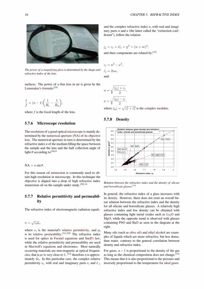
Refraction of light at the interface between two media of differentrefractive indices, with n2 > n1. Since the phase velocity is lowerin the second medium (v2 < v1), the angle of refraction θ2 is lessthan the angle of incidence θ1; that is, the ray in the higher-indexmedium is closer to the normal.
When light moves from one medium to another, itchanges direction, i.e. it is refracted. If it moves froma medium with refractive index n1 to one with refractiveindex n2, with an incidence angle to the surface normal ofθ1, the refraction angle θ2 can be calculated from Snell’slaw:[25]
n1 sin θ1 = n2 sin θ2.
When light enters a material with higher refractive index,the angle of refraction will be smaller than the angle of in-cidence and the light will be refracted towards the normalof the surface. The higher the refractive index, the closerto the normal direction the light will travel. When pass-ing into a medium with lower refractive index, the lightwill instead be refracted away from the normal, towardsthe surface.
5.7.3 Total internal reflection
If there is no angle θ2 fulfilling Snell’s law, i.e.,
n1
n2sin θ1 > 1,
the light cannot be transmitted and will instead undergototal internal reflection.[26]:49–50 This occurs only when
Total internal reflection can be seen at the air-water boundary.
going to a less optically dense material, i.e., one withlower refractive index. To get total internal reflection theangles of incidence θ1 must be larger than the criticalangle[27]
θc = arcsin(n2
n1
).
5.7.4 Reflectivity
Apart from the transmitted light there is also a reflectedpart. The reflection angle is equal to the incidence angle,and the amount of light that is reflected is determined bythe reflectivity of the surface. The reflectivity can be cal-culated from the refractive index and the incidence anglewith the Fresnel equations, which for normal incidencereduces to[26]:44
R0 =
∣∣∣∣n1 − n2
n1 + n2
∣∣∣∣2.For common glass in air, n1 = 1 and n2 = 1.5, and thusabout 4% of the incident power is reflected.[28] At otherincidence angles the reflectivity will also depend on thepolarization of the incoming light. At a certain anglecalled Brewster’s angle, p-polarized light (light with theelectric field in the plane of incidence) will be totallytransmitted. Brewster’s angle can be calculated from thetwo refractive indices of the interface as [1]:245
θB = arctan(n2
n1
).
5.7.5 Lenses
The focal length of a lens is determined by its refrac-tive index n and the radii of curvature R1 and R2 of its
16 CHAPTER 5. REFRACTIVE INDEX
The power of a magnifying glass is determined by the shape andrefractive index of the lens.
surfaces. The power of a thin lens in air is given by theLensmaker’s formula:[29]
1
f= (n− 1)
(1
R1− 1
R2
),
where f is the focal length of the lens.
5.7.6 Microscope resolution
The resolution of a good optical microscope is mainly de-termined by the numerical aperture (NA) of its objectivelens. The numerical aperture in turn is determined by therefractive index n of themedium filling the space betweenthe sample and the lens and the half collection angle oflight θ according to[30]:6
NA = n sin θ.
For this reason oil immersion is commonly used to ob-tain high resolution in microscopy. In this technique theobjective is dipped into a drop of high refractive indeximmersion oil on the sample under study.[30]:14
5.7.7 Relative permittivity and permeabil-ity
The refractive index of electromagnetic radiation equals
n =√εrµr,
where εᵣ is the material’s relative permittivity, and μᵣis its relative permeability.[31]:229 The refractive indexis used for optics in Fresnel equations and Snell’s law;while the relative permittivity and permeability are usedin Maxwell’s equations and electronics. Most naturallyoccurring materials are non-magnetic at optical frequen-cies, that is μr is very close to 1, [32] therefore n is approx-imately √εᵣ. In this particular case, the complex relativepermittivity εᵣ, with real and imaginary parts εᵣ and ɛ̃ ᵣ,
and the complex refractive index n, with real and imagi-nary parts n and κ (the latter called the “extinction coef-ficient”), follow the relation
εr = εr + iε̃r = n2 = (n+ iκ)2,
and their components are related by:[33]
εr = n2 − κ2,
ε̃r = 2nκ,
and:
n =
√|εr|+ εr
2,
κ =
√|εr| − εr
2.
where |εr| =√ε2r + ε̃2r is the complex modulus.
5.7.8 Density
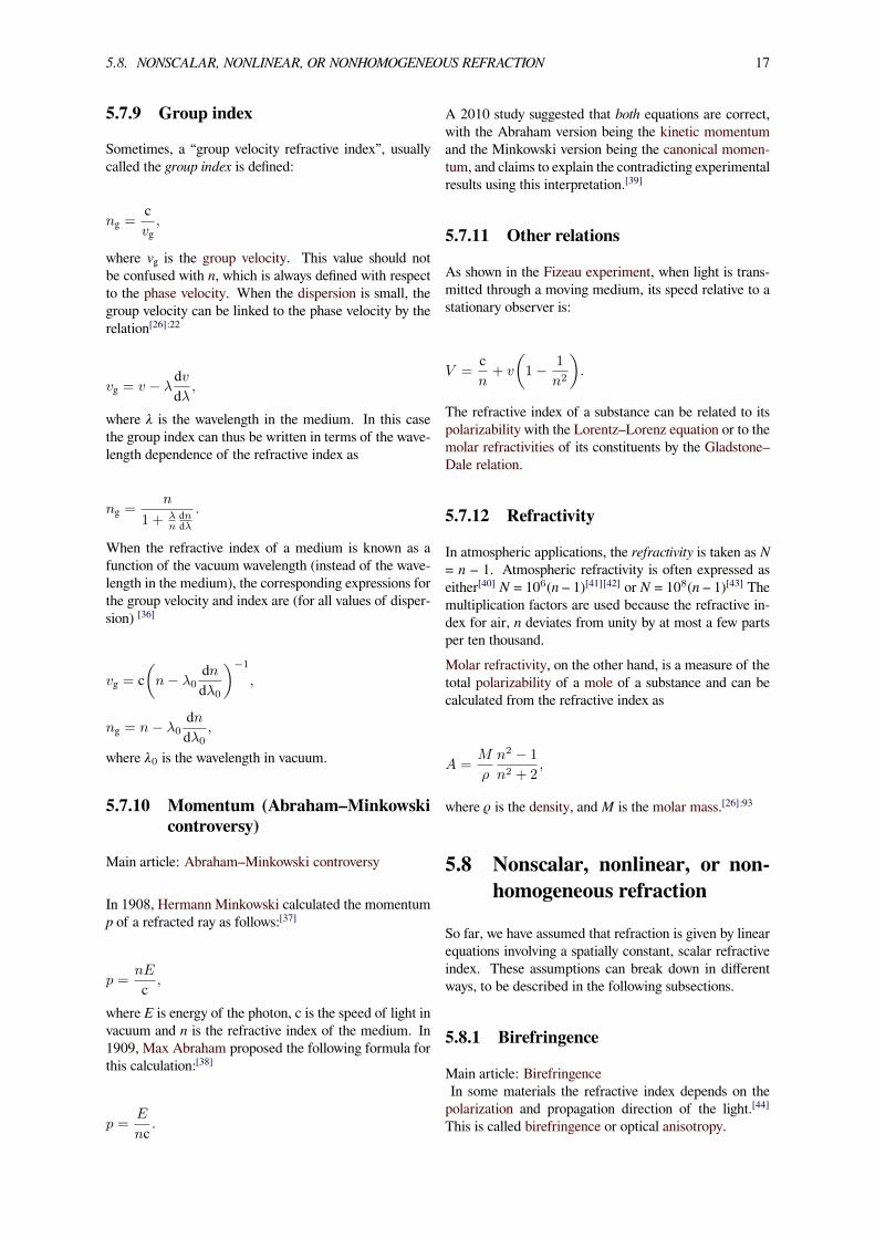
Relation between the refractive index and the density of silicateand borosilicate glasses.[34]
In general, the refractive index of a glass increases withits density. However, there does not exist an overall lin-ear relation between the refractive index and the densityfor all silicate and borosilicate glasses. A relatively highrefractive index and low density can be obtained withglasses containing light metal oxides such as Li2O andMgO, while the opposite trend is observed with glassescontaining PbO and BaO as seen in the diagram at theright.Many oils (such as olive oil) and ethyl alcohol are exam-ples of liquids which are more refractive, but less dense,than water, contrary to the general correlation betweendensity and refractive index.For gases, n − 1 is proportional to the density of the gasas long as the chemical composition does not change.[35]This means that it is also proportional to the pressure andinversely proportional to the temperature for ideal gases.
5.8. NONSCALAR, NONLINEAR, OR NONHOMOGENEOUS REFRACTION 17
5.7.9 Group index
Sometimes, a “group velocity refractive index”, usuallycalled the group index is defined:
ng =cvg,
where v is the group velocity. This value should notbe confused with n, which is always defined with respectto the phase velocity. When the dispersion is small, thegroup velocity can be linked to the phase velocity by therelation[26]:22
vg = v − λdvdλ,
where λ is the wavelength in the medium. In this casethe group index can thus be written in terms of the wave-length dependence of the refractive index as
ng =n
1 + λndndλ
.
When the refractive index of a medium is known as afunction of the vacuum wavelength (instead of the wave-length in the medium), the corresponding expressions forthe group velocity and index are (for all values of disper-sion) [36]
vg = c(n− λ0
dndλ0
)−1
,
ng = n− λ0dndλ0
,
where λ0 is the wavelength in vacuum.
5.7.10 Momentum (Abraham–Minkowskicontroversy)
Main article: Abraham–Minkowski controversy
In 1908, Hermann Minkowski calculated the momentump of a refracted ray as follows:[37]
p =nE
c ,
where E is energy of the photon, c is the speed of light invacuum and n is the refractive index of the medium. In1909, Max Abraham proposed the following formula forthis calculation:[38]
p =E
nc .
A 2010 study suggested that both equations are correct,with the Abraham version being the kinetic momentumand the Minkowski version being the canonical momen-tum, and claims to explain the contradicting experimentalresults using this interpretation.[39]
5.7.11 Other relations
As shown in the Fizeau experiment, when light is trans-mitted through a moving medium, its speed relative to astationary observer is:
V =cn+ v
(1− 1
n2
).
The refractive index of a substance can be related to itspolarizability with the Lorentz–Lorenz equation or to themolar refractivities of its constituents by the Gladstone–Dale relation.
5.7.12 Refractivity
In atmospheric applications, the refractivity is taken as N= n – 1. Atmospheric refractivity is often expressed aseither[40] N = 106(n – 1)[41][42] or N = 108(n – 1)[43] Themultiplication factors are used because the refractive in-dex for air, n deviates from unity by at most a few partsper ten thousand.Molar refractivity, on the other hand, is a measure of thetotal polarizability of a mole of a substance and can becalculated from the refractive index as
A =M
ρ
n2 − 1
n2 + 2,
where ρ is the density, and M is the molar mass.[26]:93
5.8 Nonscalar, nonlinear, or non-homogeneous refraction
So far, we have assumed that refraction is given by linearequations involving a spatially constant, scalar refractiveindex. These assumptions can break down in differentways, to be described in the following subsections.
5.8.1 Birefringence
Main article: BirefringenceIn some materials the refractive index depends on thepolarization and propagation direction of the light.[44]This is called birefringence or optical anisotropy.
18 CHAPTER 5. REFRACTIVE INDEX
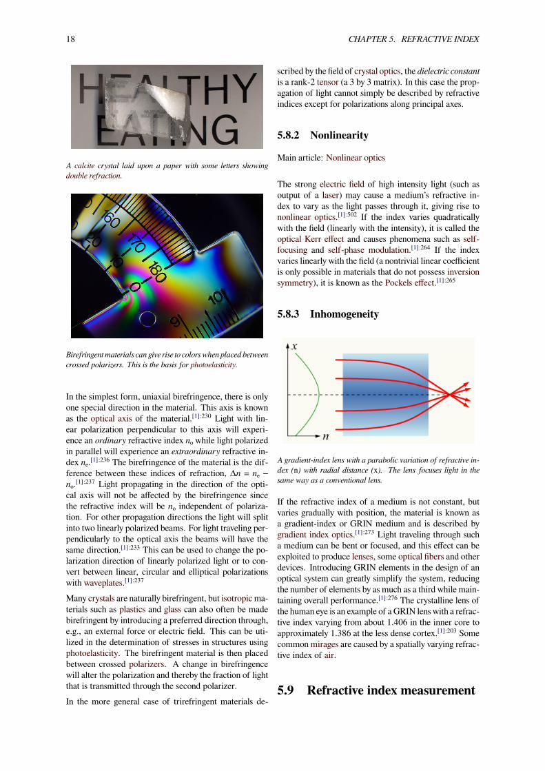
A calcite crystal laid upon a paper with some letters showingdouble refraction.
Birefringent materials can give rise to colors when placed betweencrossed polarizers. This is the basis for photoelasticity.
In the simplest form, uniaxial birefringence, there is onlyone special direction in the material. This axis is knownas the optical axis of the material.[1]:230 Light with lin-ear polarization perpendicular to this axis will experi-ence an ordinary refractive index nₒ while light polarizedin parallel will experience an extraordinary refractive in-dex nₑ.[1]:236 The birefringence of the material is the dif-ference between these indices of refraction, Δn = nₑ −nₒ.[1]:237 Light propagating in the direction of the opti-cal axis will not be affected by the birefringence sincethe refractive index will be nₒ independent of polariza-tion. For other propagation directions the light will splitinto two linearly polarized beams. For light traveling per-pendicularly to the optical axis the beams will have thesame direction.[1]:233 This can be used to change the po-larization direction of linearly polarized light or to con-vert between linear, circular and elliptical polarizationswith waveplates.[1]:237
Many crystals are naturally birefringent, but isotropic ma-terials such as plastics and glass can also often be madebirefringent by introducing a preferred direction through,e.g., an external force or electric field. This can be uti-lized in the determination of stresses in structures usingphotoelasticity. The birefringent material is then placedbetween crossed polarizers. A change in birefringencewill alter the polarization and thereby the fraction of lightthat is transmitted through the second polarizer.In the more general case of trirefringent materials de-
scribed by the field of crystal optics, the dielectric constantis a rank-2 tensor (a 3 by 3 matrix). In this case the prop-agation of light cannot simply be described by refractiveindices except for polarizations along principal axes.
5.8.2 Nonlinearity
Main article: Nonlinear optics
The strong electric field of high intensity light (such asoutput of a laser) may cause a medium’s refractive in-dex to vary as the light passes through it, giving rise tononlinear optics.[1]:502 If the index varies quadraticallywith the field (linearly with the intensity), it is called theoptical Kerr effect and causes phenomena such as self-focusing and self-phase modulation.[1]:264 If the indexvaries linearly with the field (a nontrivial linear coefficientis only possible in materials that do not possess inversionsymmetry), it is known as the Pockels effect.[1]:265
5.8.3 Inhomogeneity
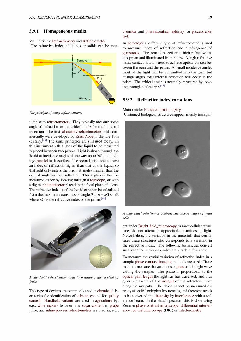
A gradient-index lens with a parabolic variation of refractive in-dex (n) with radial distance (x). The lens focuses light in thesame way as a conventional lens.
If the refractive index of a medium is not constant, butvaries gradually with position, the material is known asa gradient-index or GRIN medium and is described bygradient index optics.[1]:273 Light traveling through sucha medium can be bent or focused, and this effect can beexploited to produce lenses, some optical fibers and otherdevices. Introducing GRIN elements in the design of anoptical system can greatly simplify the system, reducingthe number of elements by as much as a third while main-taining overall performance.[1]:276 The crystalline lens ofthe human eye is an example of aGRIN lens with a refrac-tive index varying from about 1.406 in the inner core toapproximately 1.386 at the less dense cortex.[1]:203 Somecommon mirages are caused by a spatially varying refrac-tive index of air.
5.9 Refractive index measurement
5.9. REFRACTIVE INDEX MEASUREMENT 19
5.9.1 Homogeneous media
Main articles: Refractometry and RefractometerThe refractive index of liquids or solids can be mea-
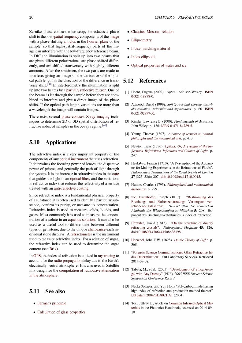
The principle of many refractometers.
sured with refractometers. They typically measure someangle of refraction or the critical angle for total internalreflection. The first laboratory refractometers sold com-mercially were developed by Ernst Abbe in the late 19thcentury.[45] The same principles are still used today. Inthis instrument a thin layer of the liquid to be measuredis placed between two prisms. Light is shone through theliquid at incidence angles all the way up to 90°, i.e., lightrays parallel to the surface. The second prism should havean index of refraction higher than that of the liquid, sothat light only enters the prism at angles smaller than thecritical angle for total reflection. This angle can then bemeasured either by looking through a telescope, or witha digital photodetector placed in the focal plane of a lens.The refractive index n of the liquid can then be calculatedfrom the maximum transmission angle θ as n = nG sin θ,where nG is the refractive index of the prism.[46]
A handheld refractometer used to measure sugar content offruits.
This type of devices are commonly used in chemical lab-oratories for identification of substances and for qualitycontrol. Handheld variants are used in agriculture by,e.g., wine makers to determine sugar content in grapejuice, and inline process refractometers are used in, e.g.,
chemical and pharmaceutical industry for process con-trol.In gemology a different type of refractometer is usedto measure index of refraction and birefringence ofgemstones. The gem is placed on a high refractive in-dex prism and illuminated from below. A high refractiveindex contact liquid is used to achieve optical contact be-tween the gem and the prism. At small incidence anglesmost of the light will be transmitted into the gem, butat high angles total internal reflection will occur in theprism. The critical angle is normally measured by look-ing through a telescope.[47]
5.9.2 Refractive index variations
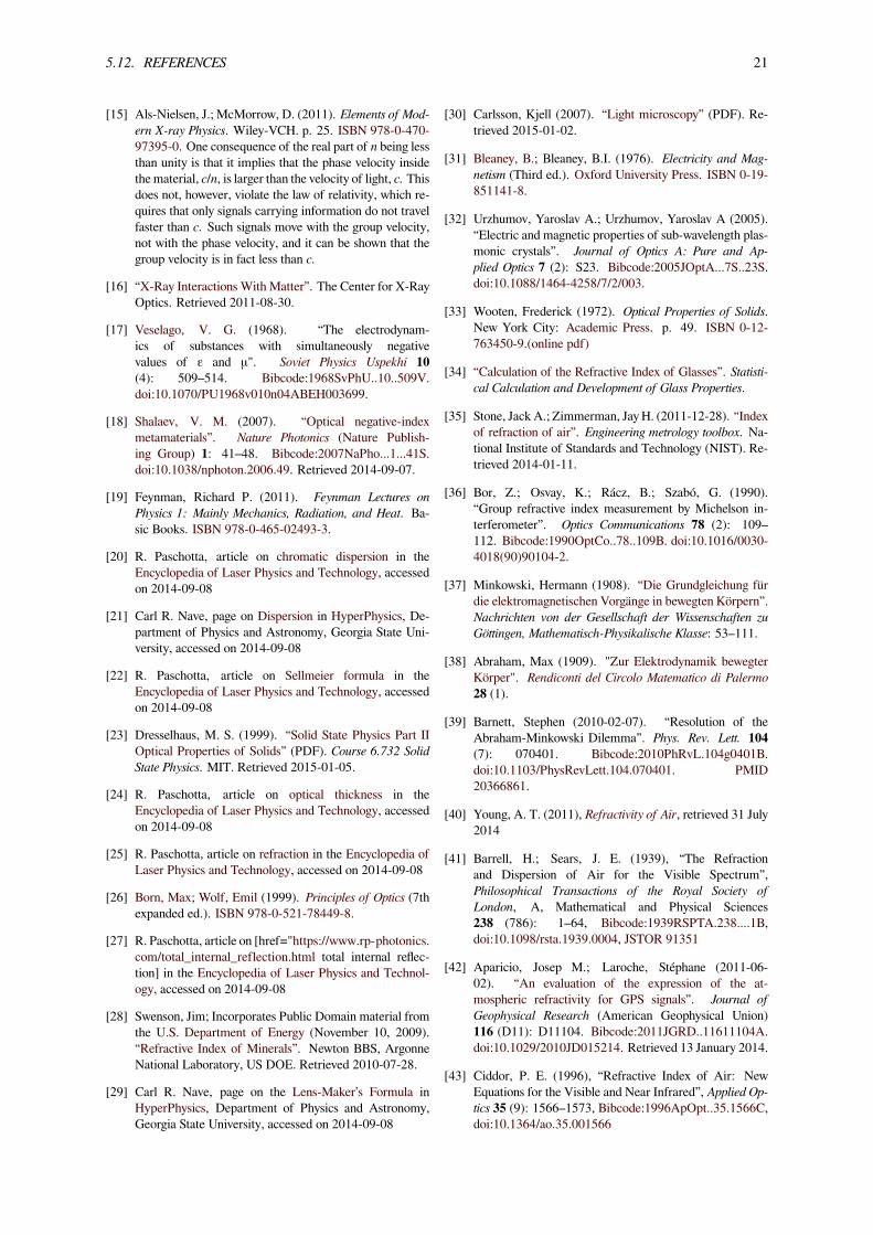
Main article: Phase-contrast imagingUnstained biological structures appear mostly transpar-
A differential interference contrast microscopy image of yeastcells.
ent under Bright-field_microscopy as most cellular struc-tures do not attenuate appreciable quantities of light.Nevertheless, the variation in the materials that consti-tutes these structures also corresponds to a variation inthe refractive index. The following techniques convertsuch variation into measurable amplitude differences:To measure the spatial variation of refractive index in asample phase-contrast imaging methods are used. Thesemethods measure the variations in phase of the light waveexiting the sample. The phase is proportional to theoptical path length the light ray has traversed, and thusgives a measure of the integral of the refractive indexalong the ray path. The phase cannot be measured di-rectly at optical or higher frequencies, and therefore needsto be converted into intensity by interference with a ref-erence beam. In the visual spectrum this is done usingZernike phase-contrast microscopy, differential interfer-ence contrast microscopy (DIC) or interferometry.
20 CHAPTER 5. REFRACTIVE INDEX
Zernike phase-contrast microscopy introduces a phaseshift to the low spatial frequency components of the imagewith a phase-shifting annulus in the Fourier plane of thesample, so that high-spatial-frequency parts of the im-age can interfere with the low-frequency reference beam.In DIC the illumination is split up into two beams thatare given different polarizations, are phase shifted differ-ently, and are shifted transversely with slightly differentamounts. After the specimen, the two parts are made tointerfere, giving an image of the derivative of the opti-cal path length in the direction of the difference in trans-verse shift.[30] In interferometry the illumination is splitup into two beams by a partially reflective mirror. One ofthe beams is let through the sample before they are com-bined to interfere and give a direct image of the phaseshifts. If the optical path length variations are more thana wavelength the image will contain fringes.There exist several phase-contrast X-ray imaging tech-niques to determine 2D or 3D spatial distribution of re-fractive index of samples in the X-ray regime.[48]
5.10 Applications
The refractive index is a very important property of thecomponents of any optical instrument that uses refraction.It determines the focusing power of lenses, the dispersivepower of prisms, and generally the path of light throughthe system. It is the increase in refractive index in the corethat guides the light in an optical fiber, and the variationsin refractive index that reduces the reflectivity of a surfacetreated with an anti-reflective coating.Since refractive index is a fundamental physical propertyof a substance, it is often used to identify a particular sub-stance, confirm its purity, or measure its concentration.Refractive index is used to measure solids, liquids, andgases. Most commonly it is used to measure the concen-tration of a solute in an aqueous solution. It can also beused as a useful tool to differentiate between differenttypes of gemstone, due to the unique chatoyance each in-dividual stone displays. A refractometer is the instrumentused to measure refractive index. For a solution of sugar,the refractive index can be used to determine the sugarcontent (see Brix).In GPS, the index of refraction is utilized in ray-tracing toaccount for the radio propagation delay due to the Earth’selectrically neutral atmosphere. It is also used in Satellitelink design for the computation of radiowave attenuationin the atmosphere.
5.11 See also
• Fermat’s principle
• Calculation of glass properties
• Clausius–Mossotti relation
• Ellipsometry
• Index-matching material
• Index ellipsoid
• Optical properties of water and ice
5.12 References[1] Hecht, Eugene (2002). Optics. Addison-Wesley. ISBN
0-321-18878-0.
[2] Attwood, David (1999). Soft X-rays and extreme ultravi-olet radiation: principles and applications. p. 60. ISBN0-521-02997-X.
[3] Kinsler, Lawrence E. (2000). Fundamentals of Acoustics.John Wiley. p. 136. ISBN 0-471-84789-5.
[4] Young, Thomas (1807). A course of lectures on naturalphilosophy and the mechanical arts. p. 413.
[5] Newton, Isaac (1730). Opticks: Or, A Treatise of the Re-flections, Refractions, Inflections and Colours of Light. p.247.
[6] Hauksbee, Francis (1710). “A Description of the Appara-tus forMaking Experiments on the Refractions of Fluids”.Philosophical Transactions of the Royal Society of London27 (325–336): 207. doi:10.1098/rstl.1710.0015.
[7] Hutton, Charles (1795). Philosophical and mathematicaldictionary. p. 299.
[8] von Fraunhofer, Joseph (1817). “Bestimmung desBrechungs und Farbenzerstreuungs Vermogens ver-schiedener Glasarten”. Denkschriften der KöniglichenAkademie der Wissenschaften zu München 5: 208. Ex-ponent des Brechungsverhältnisses is index of refraction
[9] Brewster, David (1815). “On the structure of doublyrefracting crystals”. Philosophical Magazine 45: 126.doi:10.1080/14786441508638398.
[10] Herschel, John F.W. (1828). On the Theory of Light. p.368.
[11] “Forensic Science Communications, Glass Refractive In-dex Determination”. FBI Laboratory Services. Retrieved2014-09-08.
[12] Tabata, M.; et al. (2005). “Development of Silica Aero-gel with Any Density” (PDF). 2005 IEEE Nuclear ScienceSymposium Conference Record.
[13] Naoki Sadayori and Yuji Hotta “Polycarbodiimide havinghigh index of refraction and production method thereof”US patent 2004/0158021 A1 (2004)
[14] Tosi, Jeffrey L., article on Common Infrared Optical Ma-terials in the Photonics Handbook, accessed on 2014-09-10
5.12. REFERENCES 21
[15] Als-Nielsen, J.; McMorrow, D. (2011). Elements of Mod-ern X-ray Physics. Wiley-VCH. p. 25. ISBN 978-0-470-97395-0. One consequence of the real part of n being lessthan unity is that it implies that the phase velocity insidethematerial, c/n, is larger than the velocity of light, c. Thisdoes not, however, violate the law of relativity, which re-quires that only signals carrying information do not travelfaster than c. Such signals move with the group velocity,not with the phase velocity, and it can be shown that thegroup velocity is in fact less than c.
[16] “X-Ray Interactions With Matter”. The Center for X-RayOptics. Retrieved 2011-08-30.
[17] Veselago, V. G. (1968). “The electrodynam-ics of substances with simultaneously negativevalues of ε and μ". Soviet Physics Uspekhi 10(4): 509–514. Bibcode:1968SvPhU..10..509V.doi:10.1070/PU1968v010n04ABEH003699.
[18] Shalaev, V. M. (2007). “Optical negative-indexmetamaterials”. Nature Photonics (Nature Publish-ing Group) 1: 41–48. Bibcode:2007NaPho...1...41S.doi:10.1038/nphoton.2006.49. Retrieved 2014-09-07.
[19] Feynman, Richard P. (2011). Feynman Lectures onPhysics 1: Mainly Mechanics, Radiation, and Heat. Ba-sic Books. ISBN 978-0-465-02493-3.
[20] R. Paschotta, article on chromatic dispersion in theEncyclopedia of Laser Physics and Technology, accessedon 2014-09-08
[21] Carl R. Nave, page on Dispersion in HyperPhysics, De-partment of Physics and Astronomy, Georgia State Uni-versity, accessed on 2014-09-08
[22] R. Paschotta, article on Sellmeier formula in theEncyclopedia of Laser Physics and Technology, accessedon 2014-09-08
[23] Dresselhaus, M. S. (1999). “Solid State Physics Part IIOptical Properties of Solids” (PDF). Course 6.732 SolidState Physics. MIT. Retrieved 2015-01-05.
[24] R. Paschotta, article on optical thickness in theEncyclopedia of Laser Physics and Technology, accessedon 2014-09-08
[25] R. Paschotta, article on refraction in the Encyclopedia ofLaser Physics and Technology, accessed on 2014-09-08
[26] Born, Max; Wolf, Emil (1999). Principles of Optics (7thexpanded ed.). ISBN 978-0-521-78449-8.
[27] R. Paschotta, article on [href="https://www.rp-photonics.com/total_internal_reflection.html total internal reflec-tion] in the Encyclopedia of Laser Physics and Technol-ogy, accessed on 2014-09-08
[28] Swenson, Jim; Incorporates Public Domain material fromthe U.S. Department of Energy (November 10, 2009).“Refractive Index of Minerals”. Newton BBS, ArgonneNational Laboratory, US DOE. Retrieved 2010-07-28.
[29] Carl R. Nave, page on the Lens-Maker’s Formula inHyperPhysics, Department of Physics and Astronomy,Georgia State University, accessed on 2014-09-08
[30] Carlsson, Kjell (2007). “Light microscopy” (PDF). Re-trieved 2015-01-02.
[31] Bleaney, B.; Bleaney, B.I. (1976). Electricity and Mag-netism (Third ed.). Oxford University Press. ISBN 0-19-851141-8.
[32] Urzhumov, Yaroslav A.; Urzhumov, Yaroslav A (2005).“Electric and magnetic properties of sub-wavelength plas-monic crystals”. Journal of Optics A: Pure and Ap-plied Optics 7 (2): S23. Bibcode:2005JOptA...7S..23S.doi:10.1088/1464-4258/7/2/003.
[33] Wooten, Frederick (1972). Optical Properties of Solids.New York City: Academic Press. p. 49. ISBN 0-12-763450-9.(online pdf)
[34] “Calculation of the Refractive Index of Glasses”. Statisti-cal Calculation and Development of Glass Properties.
[35] Stone, JackA.; Zimmerman, JayH. (2011-12-28). “Indexof refraction of air”. Engineering metrology toolbox. Na-tional Institute of Standards and Technology (NIST). Re-trieved 2014-01-11.
[36] Bor, Z.; Osvay, K.; Rácz, B.; Szabó, G. (1990).“Group refractive index measurement by Michelson in-terferometer”. Optics Communications 78 (2): 109–112. Bibcode:1990OptCo..78..109B. doi:10.1016/0030-4018(90)90104-2.
[37] Minkowski, Hermann (1908). “Die Grundgleichung fürdie elektromagnetischen Vorgänge in bewegten Körpern”.Nachrichten von der Gesellschaft der Wissenschaften zuGöttingen, Mathematisch-Physikalische Klasse: 53–111.
[38] Abraham, Max (1909). "Zur Elektrodynamik bewegterKörper". Rendiconti del Circolo Matematico di Palermo28 (1).
[39] Barnett, Stephen (2010-02-07). “Resolution of theAbraham-Minkowski Dilemma”. Phys. Rev. Lett. 104(7): 070401. Bibcode:2010PhRvL.104g0401B.doi:10.1103/PhysRevLett.104.070401. PMID20366861.
[40] Young, A. T. (2011), Refractivity of Air, retrieved 31 July2014
[41] Barrell, H.; Sears, J. E. (1939), “The Refractionand Dispersion of Air for the Visible Spectrum”,Philosophical Transactions of the Royal Society ofLondon, A, Mathematical and Physical Sciences238 (786): 1–64, Bibcode:1939RSPTA.238....1B,doi:10.1098/rsta.1939.0004, JSTOR 91351
[42] Aparicio, Josep M.; Laroche, Stéphane (2011-06-02). “An evaluation of the expression of the at-mospheric refractivity for GPS signals”. Journal ofGeophysical Research (American Geophysical Union)116 (D11): D11104. Bibcode:2011JGRD..11611104A.doi:10.1029/2010JD015214. Retrieved 13 January 2014.
[43] Ciddor, P. E. (1996), “Refractive Index of Air: NewEquations for the Visible and Near Infrared”, Applied Op-tics 35 (9): 1566–1573, Bibcode:1996ApOpt..35.1566C,doi:10.1364/ao.35.001566
22 CHAPTER 5. REFRACTIVE INDEX
[44] R. Paschotta, article on birefringence in the Encyclopediaof Laser Physics and Technology, accessed on 2014-09-09
[45] “The Evolution of the Abbe Refractometer”. HumboldtState University, Richard A. Paselk. 1998. Retrieved2011-09-03.
[46] “Refractometers and refractometry”. Refractometer.pl.2011. Retrieved 2011-09-03.
[47] “Refractometer”. The Gemology Project. Retrieved2011-09-03.
[48] Fitzgerald, Richard (July 2000). “Phase‐SensitiveX‐Ray Imaging”. Physics Today 53 (7): 23.Bibcode:2000PhT....53g..23F. doi:10.1063/1.1292471.
5.13 External links• NIST calculator for determining the refractive indexof air
• Dielectric materials
• Science World
• Filmetrics’ online database Free database of refrac-tive index and absorption coefficient information
• RefractiveIndex.INFO Refractive index databasefeaturing online plotting and parameterisation ofdata
• sopra-sa.com Refractive index database as text files(sign-up required)
• LUXPOP Thin film and bulk index of refraction andphotonics calculations
Chapter 6
Prism spectrometer
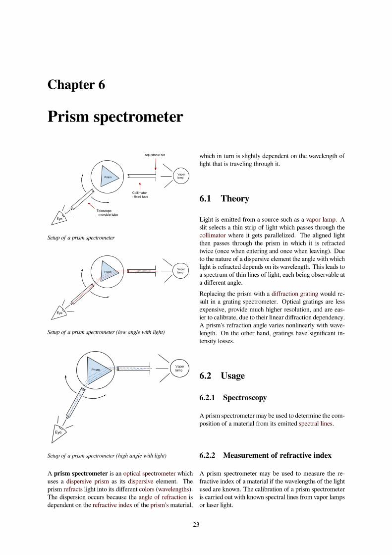
Setup of a prism spectrometer
Setup of a prism spectrometer (low angle with light)
Setup of a prism spectrometer (high angle with light)
A prism spectrometer is an optical spectrometer whichuses a dispersive prism as its dispersive element. Theprism refracts light into its different colors (wavelengths).The dispersion occurs because the angle of refraction isdependent on the refractive index of the prism’s material,
which in turn is slightly dependent on the wavelength oflight that is traveling through it.
6.1 Theory
Light is emitted from a source such as a vapor lamp. Aslit selects a thin strip of light which passes through thecollimator where it gets parallelized. The aligned lightthen passes through the prism in which it is refractedtwice (once when entering and once when leaving). Dueto the nature of a dispersive element the angle with whichlight is refracted depends on its wavelength. This leads toa spectrum of thin lines of light, each being observable ata different angle.Replacing the prism with a diffraction grating would re-sult in a grating spectrometer. Optical gratings are lessexpensive, provide much higher resolution, and are eas-ier to calibrate, due to their linear diffraction dependency.A prism’s refraction angle varies nonlinearly with wave-length. On the other hand, gratings have significant in-tensity losses.
6.2 Usage
6.2.1 Spectroscopy
A prism spectrometer may be used to determine the com-position of a material from its emitted spectral lines.
6.2.2 Measurement of refractive index
A prism spectrometer may be used to measure the re-fractive index of a material if the wavelengths of the lightused are known. The calibration of a prism spectrometeris carried out with known spectral lines from vapor lampsor laser light.
23
24 CHAPTER 6. PRISM SPECTROMETER
6.3 External links• The prism spectrometer Physics Laboratory Guide,Durham University
• The Prism Spectrometer
• Spectrometer, Refractive Index of the material of aprism Virtual Laboratory, Amrita University
6.4. TEXT AND IMAGE SOURCES, CONTRIBUTORS, AND LICENSES 25
6.4 Text and image sources, contributors, and licenses
6.4.1 Text• Spectrometer Source: https://en.wikipedia.org/wiki/Spectrometer?oldid=676465986 Contributors: Vsmith, Kkmurray, HPaul, Ronningt,
Download, Tom.Reding, ClueBot NG, BG19bot, Crystallizedcarbon, KasparBot and Anonymous: 3• Prism Source: https://en.wikipedia.org/wiki/Prism?oldid=683039989 Contributors: DrBob, Patrick, Michael Hardy, Glenn, Tantalate,
Saltine, Robbot, Hankwang, Chris 73, Altenmann, DHN, Hadal, Xanzzibar, Reytan, Mintleaf~enwiki, Fudoreaper, BenFrantzDale, ÆvarArnfjörð Bjarmason, AJim, Andycjp, Chris Howard, Bumphoney, Magic5ball, Vsmith, Pavel Vozenilek, El C, Huntster, Semper discens,Smalljim, Flammifer, Einar Myre, Mareino, Jumbuck, Snowolf, Lokedhs, Sakus, Alai, HenryLi, Kazvorpal, Kmg90, Xiong, Nanite, Saper-aud~enwiki, TeemuN, Johnrpenner, FlaBot, RexNL, Srleffler, Spencerk, Johnpenner, Bgwhite, YurikBot, RobotE, RussBot, SpuriousQ,Eleassar, Wimt, ErkDemon, DeadEyeArrow, BorgQueen, JoanneB, Alexandrov, GrinBot~enwiki, Cmglee, SmackBot, Gilliam, Saros136,DHN-bot~enwiki, Can't sleep, clown will eat me, MastaTKK367, Lizzielizzielizzie, SundarBot, CanDo, Baby-g, Jidanni, Robofish, Iron-Gargoyle, Grumpyyoungman01, Dicklyon, Citicat, Tawkerbot2, NickSpiker, Karenjc, Meno25, Gogo Dodo, Quibik, Vanished User jdks-fajlasd, Justinp93, PKT, Michael Fourman, Thijs!bot, Headbomb, Rlupsa, Escarbot, AntiVandalBot, Widefox, BailesB, Tomorrow NeverKnows, Magioladitis, RogierBrussee, VoABot II, MartinBot, CommonsDelinker, J.delanoy, Hans Dunkelberg, Acalamari, Rod57, Shawn inMontreal, Afluegel, Joshua Issac, DorganBot, D-Kuru, VolkovBot, NathanHagen, TXiKiBoT, NPrice, Qxz, LeaveSleaves, Cremepuff222,Trueemo, Spinningspark, AlleborgoBot, Symane, SieBot, Trent17 99, Gerakibot, Dawn Bard, Caltas, Flyer22, Aruton, Oxymoron83, An-tonio Lopez, WingkeeLEE, BenoniBot~enwiki, ClueBot, Frdayeen, Adrian dakota, Manishearth, Paul Pot, Computer97, Thingg, Versus22,Adrian Teh, Darkicebot, XLinkBot, RP459, Addbot, Guoguo12, Jncraton, CanadianLinuxUser, Chzz, Tide rolls, Arnoques, Luckas-bot,Amirobot, Rrokkedd, AnomieBOT, Ciphers, Jim1138, Materialscientist, Citation bot, ArthurBot, Xqbot, Corrigendas, Frosted14, Ribot-BOT, Doulos Christos, Captain-n00dle, Hexicola, D'ohBot, Steve Quinn, Craig Pemberton, Valerian456, Lskil09, Pinethicket, Monkey-fox, Dinamik-bot, UNIT A4B1, Weedwhacker128, TheMesquito, Marie Poise, TjBot, Ripchip Bot, Nyxaus, Petar607, EmausBot, OrphanWiki, ZéroBot, Josve05a, AManWithNoPlan, ClueBot NG, CocuBot, Widr, Aniketmh035569, Helpful Pixie Bot, Sandro-xxx, BibcodeBot, Jeraphine Gryphon, Wikgeek11, Tom Pippens, NotWith, Achowat, Lugia2453, SFK2, Telfordbuck, 069952497a, NottNott, Quenhi-tran, Smellypoos, Kali David Heffernan, Argailyasa, Xturtle MasterX, Amortias, Speakfromthesoul, ToonLucas22, Alex macneil, Clicksm,KasparBot, Bobtobs, G.Edenhofer and Anonymous: 226
• Minimum deviation Source: https://en.wikipedia.org/wiki/Minimum_deviation?oldid=670193920 Contributors: David Gerard, Icairns,Kwamikagami, SmackBot, Pieter Kuiper, Wayne Miller, Biscuittin, WingkeeLEE, KathrynLybarger, ClueBot, Yobot, Capricorn42,PhysicsR, GoingBatty, Gowtham vmj, Scientific29, Cjb9212, Mogism, SiBr4, Supdiop and Anonymous: 18
• Angle of incidence Source: https://en.wikipedia.org/wiki/Angle_of_incidence?oldid=671348001 Contributors: Fubar Obfusco, SimonP,Maury Markowitz, Michael Hardy, Sergiusz Patela, Theresa knott, GRAHAMUK, Syclop, UtherSRG, BenFrantzDale, Frencheigh, Vess-bot, Tomruen, Trevor MacInnis, Rich Farmbrough, CanisRufus, Bobo192, Meggar, Mac Davis, IMeowbot, Shoefly, Eaolson, Rjwilmsi,Vegaswikian, Maustrauser, Srleffler, Kri, Chobot, Splintercellguy, Ssbohio, Moralis, Bluebot, Viewfinder, Eynar, UVnet, Pflatau, 16@r,Dicklyon, JMK, Domitori, Tawkerbot2, Cydebot, Matt.S., KrakatoaKatie, AntiVandalBot, Akradecki, RebelRobot, VoABot II, Cat-slash, Appraiser, Andreas 06, Nobuts, Bdodo1992, Kyle the bot, Bosoxs 2000, Madhero88, Robo.mind, Blood sliver, Struway, Manway,Spooky1966, Dolphin51, Muhends, ClueBot, Ideal gas equation, Ariadacapo, DumZiBoT, WikHead, RyanCross, Addbot, Fgnievinski,Fieldday-sunday, Coffeeassured, Mpfiz, Yobot, Ptbotgourou, AnomieBOT, Agentex, Erik9bot, Gummer85, Pinethicket, FrozenPencil,DexDor, Mikko raikkonen, Torturella, Wikipelli, Hhhippo, Joshua Doubek, MonoAV, ChuispastonBot, ClueBot NG, Jay8g, Mrt3366,Josell2, Filedelinkerbot, Neilstraus and Anonymous: 59
• Refractive index Source: https://en.wikipedia.org/wiki/Refractive_index?oldid=684659646 Contributors: Bryan Derksen, Tarquin,XJaM, Fredbauder, DrBob, Bdesham, Michael Hardy, W~enwiki, Fwappler, Looxix~enwiki, Ellywa, Stevenj, Tantalate, Andrevan, Max-imus Rex, Donarreiskoffer, Gentgeen, Robbot, Hankwang, Eman, RedWolf, Yelyos, Chris Roy, Robinh, Diberri, Syntax~enwiki, Centrx,Giftlite, Smjg, Harp, BenFrantzDale, Xerxes314, TomViza, Hugh2414, Nayuki, Jurema Oliveira, Selva, Aulis Eskola, Grm wnr, Danh, L-H, Geof, DanielCD, Rich Farmbrough, Vsmith, R6144, Graceej, Rgdboer, Causa sui, Kjkolb, RPaschotta, Neonumbers, Keenan Pepper,Benjah-bmm27, MattWade, Velella, Dirac1933, Oleg Alexandrov, Linas, Jimbryho, JonBirge, Wurzel~enwiki, Isnow, Bobmilkman, Seven-tyThree, GraemeLeggett, Askewmind, Graham87, Rjwilmsi, Ceinturion, MZMcBride, S Schaffter, FlaBot, Weihao.chiu~enwiki, Arnero,Latka, DrVeghead, Fresheneesz, Goudzovski, Srleffler, Chobot, YurikBot, RobotE, Rowan Moore, Pigman, Sasuke Sarutobi, Kirill Lok-shin, Chrisada~enwiki, TDogg310, Dbfirs, Bota47, Rallette, Elkman, Petri Krohn, GraemeL, Pentasyllabic, Sbyrnes321, Finell, SmackBot,RDBury, The Photon, Gilliam, Jlsilva, Marc Kupper, Chris the speller, Bluebot, Oli Filth, Leifisme, Complexica, Metacomet, Jfsamper,DHN-bot~enwiki, A. B., Can't sleep, clown will eat me, Nick Levine, Mpolianski~enwiki, Smokefoot, Jbergquist, Mwtoews, DMacks,Rhkramer, JMO, Stefano85, Lambiam, Akhlesh, Nick Green, Mksword, Pflatau, Jonasbinding, Mr Stephen, Rogerbrent, Erwin, MTS-bot~enwiki, Vincecate, DabMachine, Pgadfor, Mrainer, Andreas Rejbrand, Jaksmata, Tawkerbot2, Hammer Raccoon, Kingoomieiii, Do-manix, Chrumps, NickSpiker, Aubrey Jaffer, Icek~enwiki, Cydebot, Difluoroethene, Skittleys, SteveMcCluskey, Msebast~enwiki, ,הסרפדBarticus88, Frozenport, Headbomb, Pjvpjv, John254, Timbercon, Ingolfson, CosineKitty, Swpb, Georgeasdf, UnaLaguna, Daarznieks, JJHarrison, DerHexer, Hbent, MartinBot, CommonsDelinker, Extransit, Nemo bis, Afluegel, Mikael Häggström, Chiswick Chap, BigHair-Ref, Squids and Chips, VolkovBot, DeftTechie, TXiKiBoT, Martin451, Falcon8765, Zebas, Jovial Air, Gerakibot, Jason Patton, Keilana,Pigletion, Sunrise, Spitfire19, Wsmith202~enwiki, Klsyking, ClueBot, Pointillist, Awickert, Gnome de plume, Eeekster, Rwestafer, Brewsohare, Arjayay, SchreiberBike, ChrisHodgesUK, Omer88f, Crowsnest, RexxS, Forbes72, Deszoeke, Boyfarrell, Srhat, Addbot, DOI bot,Fgnievinski, TutterMouse, Fluffernutter, Asymptotic wiki, MrOllie, Download, CarsracBot, TStein, BobK31416, Tide rolls, Finley08, Gail,Zorrobot, Quantumobserver, Skippy le Grand Gourou, Luckas-bot, Yobot, Amirobot, Litherum, Gelbukh, Feldkurat Katz, AnomieBOT,Rubinbot, AdjustShift, Materialscientist, Citation bot, ArthurBot, Xqbot, Nasnema, Anon423, Raffamaiden, Turk oğlan, NOrbeck, A. diM., Acky69, Paisiello2, K217, DKToptics, Mfwitten, Steve Quinn, Dome1ioun1, DivineAlpha, Citation bot 1, Maggyero, Pinethicket,Matt.urq, Ionelenadaniela, Gryllida, Orenburg1, Double sharp, 0x30114, LogAntiLog, RjwilmsiBot, TheArguer, Mod mmg, Ankid,Yuhuach, VoteITP, Racerx11, Koilon, Δ, Brandmeister, Donner60, Carmichael, RockMagnetist, Hiukkas, Mjbmrbot, Thuytnguyen48,ClueBot NG, Ulflund, Pradeep717, Gilderien, Wgolf, Touchlee, Helpful Pixie Bot, Bibcode Bot, BG19bot, Yosemite29brandon, Nsda,Jeffluo1011, Skkies, Vswitchs, Wannabemodel, 786b6364, Graphium, Josell2, Reatlas, ChrisCharma, PC-XT, Antuanne, Visura1, Izhaq,Monkbot, Martinmagnuson, Nandktech, Votingstar, TaeYunPark, Colin2702, Bunnycarrot9898, David G Pedia, Bobfelix38, Kekking434,KiarashKevin, Tranttipsy8888, Intrinsico, WhyWillSheNotDoTheNastyWithMe and Anonymous: 290
• Prism spectrometer Source: https://en.wikipedia.org/wiki/Prism_spectrometer?oldid=684457415 Contributors: Srleffler, Stefan2,Philg88, Revent, Yobot, Elee, Josve05a, BattyBot and G.Edenhofer

26 CHAPTER 6. PRISM SPECTROMETER
6.4.2 Images• File:Aircraft_Angle_of_Incidence_(improved)-$-$1080x660-$-$25Mar2009.jpg Source: https://upload.wikimedia.org/wikipedia/
en/0/0e/Aircraft_Angle_of_Incidence_%28improved%29-$-$1080x660-$-$25Mar2009.jpg License: PD Contributors:Own workOriginal artist:Gummer85 (talk) (Uploads)
• File:Angle_of_incidence.svg Source: https://upload.wikimedia.org/wikipedia/commons/3/30/Angle_of_incidence.svg License: Publicdomain Contributors: Own work Original artist: Andreas 06
• File:Brillanten.jpg Source: https://upload.wikimedia.org/wikipedia/commons/6/6f/Brillanten.jpg License: CC-BY-SA-3.0 Contributors:Self-photographed Original artist: Mario Sarto
• File:Calcite.jpg Source: https://upload.wikimedia.org/wikipedia/commons/7/7a/Calcite.jpg License: Public domain Contributors: ? Orig-inal artist: ?
• File:Commons-logo.svg Source: https://upload.wikimedia.org/wikipedia/en/4/4a/Commons-logo.svg License: ? Contributors: ? Originalartist: ?
• File:Comparison_refraction_diffraction_spectra.svg Source: https://upload.wikimedia.org/wikipedia/commons/1/10/Comparison_refraction_diffraction_spectra.svg License: CC BY-SA 3.0 Contributors: Own work Original artist: Cmglee
• File:Deflection_of_light_ray_passing_through_prism.png Source: https://upload.wikimedia.org/wikipedia/commons/9/98/Deflection_of_light_ray_passing_through_prism.png License: CC BY-SA 3.0 Contributors: created in powerpoint Original artist:PhysicsR
• File:Density-nd.GIF Source: https://upload.wikimedia.org/wikipedia/en/3/3b/Density-nd.GIF License: PD Contributors: ? Originalartist: ?
• File:Deviation_angle_of_a_beam_of_light_entering_a_medium_with_refractive_index.png Source: https://upload.wikimedia.org/wikipedia/commons/4/4c/Deviation_angle_of_a_beam_of_light_entering_a_medium_with_refractive_index.png License: CC0 Contrib-utors: PowerPoint Original artist: PhysicsR
• File:Dispersion-curve.png Source: https://upload.wikimedia.org/wikipedia/commons/2/20/Dispersion-curve.png License: CC-BY-SA-3.0 Contributors: Transferred from en.wikipedia to Commons. Original artist: DrBob at English Wikipedia
• File:Experiment_setup.svg Source: https://upload.wikimedia.org/wikipedia/commons/9/90/Experiment_setup.svg License: CC BY-SA4.0 Contributors: Own work Original artist: Gordian Edenhofer
• File:Experiment_setup_(high_angle_with_light).svg Source: https://upload.wikimedia.org/wikipedia/en/d/da/Experiment_setup_%28high_angle_with_light%29.svg License: CC-BY-SA-3.0 Contributors:own workOriginal artist:Gordian Edenhofer
• File:Experiment_setup_(low_angle_with_light).svg Source: https://upload.wikimedia.org/wikipedia/en/0/03/Experiment_setup_%28low_angle_with_light%29.svg License: CC-BY-SA-3.0 Contributors:own workOriginal artist:Gordian Edenhofer
• File:Focus01.png Source: https://upload.wikimedia.org/wikipedia/commons/4/4b/Focus01.png License: CC BY-SA 4.0 Contributors:Own work Original artist: HPaul
• File:FuerzaCentripetaLorentzP.svg Source: https://upload.wikimedia.org/wikipedia/commons/a/a9/FuerzaCentripetaLorentzP.svg Li-cense: CC BY-SA 3.0 Contributors: Own work Original artist: Jfmelero
• File:Gradndfilter.jpg Source: https://upload.wikimedia.org/wikipedia/commons/c/c2/Gradndfilter.jpg License: CC BY-SA 2.5 Contrib-utors: Transferred from en.wikipedia to Commons. Original artist: Ziggur at English Wikipedia
• File:Grin-lens.png Source: https://upload.wikimedia.org/wikipedia/commons/2/2c/Grin-lens.png License: CC-BY-SA-3.0 Contributors:? Original artist: ?
• File:Lens_triplet.svg Source: https://upload.wikimedia.org/wikipedia/commons/7/74/Lens_triplet.svg License: CC-BY-SA-3.0 Contrib-utors: Image:Lens triplet.png Original artist: Panther, Antilived
• File:Light_dispersion_conceptual_waves.gif Source: https://upload.wikimedia.org/wikipedia/commons/f/f5/Light_dispersion_conceptual_waves.gif License: Public domain Contributors: ? Original artist: ?
• File:Light_dispersion_of_a_mercury-vapor_lamp_with_a_flint_glass_prism_IPNr°0125.jpg Source: https://upload.wikimedia.org/wikipedia/commons/1/1f/Light_dispersion_of_a_mercury-vapor_lamp_with_a_flint_glass_prism_IPNr%C2%B00125.jpg License:CC BY-SA 3.0 at Contributors: Own work Original artist: D-Kuru
• File:Lupa.na.encyklopedii.jpg Source: https://upload.wikimedia.org/wikipedia/commons/f/f4/Lupa.na.encyklopedii.jpg License: Pub-lic domain Contributors: Own work Original artist: Julo
• File:Minimum_deflection_of_light_ray_passing_through_prism.png Source: https://upload.wikimedia.org/wikipedia/commons/e/e0/Minimum_deflection_of_light_ray_passing_through_prism.png License: CC BY-SA 3.0 Contributors: created in powerpoint Originalartist: PhysicsR
• File:Plastic_Protractor_Polarized_05375.jpg Source: https://upload.wikimedia.org/wikipedia/commons/e/e4/Plastic_Protractor_Polarized_05375.jpg License: CC-BY-SA-3.0 Contributors: Own Photograph Original artist: Nevit Dilmen
• File:Prism-side-fs_PNr°0117.jpg Source: https://upload.wikimedia.org/wikipedia/commons/c/cd/Prism-side-fs_PNr%C2%B00117.jpg License: CC BY-SA 3.0 at Contributors: Own work Original artist: D-Kuru
6.4. TEXT AND IMAGE SOURCES, CONTRIBUTORS, AND LICENSES 27
• File:Prism_rainbow_schema.png Source: https://upload.wikimedia.org/wikipedia/commons/0/06/Prism_rainbow_schema.png License:CC-BY-SA-3.0 Contributors: ? Original artist: ?
• File:Prism_ray_trace.svg Source: https://upload.wikimedia.org/wikipedia/commons/7/7d/Prism_ray_trace.svg License: PD Contribu-tors: ? Original artist: ?
• File:Pulfrich_refraktometer_en.png Source: https://upload.wikimedia.org/wikipedia/commons/e/ed/Pulfrich_refraktometer_en.pngLicense: CC BY-SA 2.5 Contributors: No machine-readable source provided. Own work assumed (based on copyright claims). Origi-nal artist: No machine-readable author provided. Kodak17~commonswiki assumed (based on copyright claims).
• File:Question_book-new.svg Source: https://upload.wikimedia.org/wikipedia/en/9/99/Question_book-new.svg License: Cc-by-sa-3.0Contributors:Created from scratch in Adobe Illustrator. Based on Image:Question book.png created by User:Equazcion Original artist:Tkgd2007
• File:RefractionReflextion.svg Source: https://upload.wikimedia.org/wikipedia/commons/5/5d/RefractionReflextion.svg License: CCBY-SA 3.0 Contributors: Own work Original artist: Josell7
• File:Refraction_at_interface.svg Source: https://upload.wikimedia.org/wikipedia/commons/3/3f/Refraction_at_interface.svg License:CC0 Contributors: Own work Original artist: Ulflund
• File:Refraction_photo.png Source: https://upload.wikimedia.org/wikipedia/commons/8/85/Refraction_photo.png License: Public do-main Contributors: http://www.docstoc.com/docs/130534946/Chapter-7-Refractive-index Original artist: ajizai
• File:Refractometer.jpg Source: https://upload.wikimedia.org/wikipedia/commons/9/9e/Refractometer.jpg License: CC-BY-SA-3.0Contributors: Own work Original artist: Fernando G. (FGM)
• File:S_cerevisiae_under_DIC_microscopy.jpg Source: https://upload.wikimedia.org/wikipedia/commons/d/d9/S_cerevisiae_under_DIC_microscopy.jpg License: Public domain Contributors: Own work Original artist: Masur
• File:Snells_law.svg Source: https://upload.wikimedia.org/wikipedia/commons/d/d1/Snells_law.svg License: Public domain Contributors:Transferred from en.wikipedia to Commons. Original artist: Cristan at English Wikipedia
• File:Soap_bubble_sky.jpg Source: https://upload.wikimedia.org/wikipedia/commons/1/18/Soap_bubble_sky.jpg License: CC-BY-SA-3.0 Contributors: Own work Original artist: Brocken Inaglory
• File:Split-ring_resonator_array_10K_sq_nm.jpg Source: https://upload.wikimedia.org/wikipedia/commons/8/82/Split-ring_resonator_array_10K_sq_nm.jpg License: Public domain Contributors: NASA Glenn Research Original artist: [email protected](Glenn research contact)
• File:Thomas_Young_(scientist).jpg Source: https://upload.wikimedia.org/wikipedia/commons/9/9f/Thomas_Young_%28scientist%29.jpg License: Public domain Contributors: National Portrait Gallery: NPG 1899D7714, also on gutenberg.org Original artist: AfterThomas Lawrence
• File:Total_internal_reflection_of_Chelonia_mydas.jpg Source: https://upload.wikimedia.org/wikipedia/commons/5/5c/Total_internal_reflection_of_Chelonia_mydas.jpg License: GFDL Contributors: Own work Original artist: Brocken Inaglory
• File:WhereRainbowRises.jpg Source: https://upload.wikimedia.org/wikipedia/commons/2/27/WhereRainbowRises.jpg License: CCBY-SA 2.5 Contributors: self-made; at Jasper National Park, Alberta, Canada (along Yellowhead Highway 16 between intersection toMalign Valley Road and intersection to Snaring River Campground, overlooking Colin Range in the south). Original artist: Wing-Chi Poon
6.4.3 Content license• Creative Commons Attribution-Share Alike 3.0