prism tm450 installation guide for jbus 1708 and 1939 · prism tm450 installation guide for jbus...
TRANSCRIPT
Prism TM450 Installation Guide
For JBus 1708 and 1939
Document Number: 1624-0301 00
Date: May 5, 2010

Table of Contents
Overview............................................................................................................ 1
Kit Components .............................................................................................. 1
Differences between the TM450 and the TM2J. ............................................. 2
Installation ......................................................................................................... 3
Main Power Connections. ............................................................................... 4
Alternate Power Input .................................................................................... 4
Antenna .......................................................................................................... 5
Antenna Placement ..................................................................................... 5
Hidden Antenna Placement ......................................................................... 5
Testing the Installation ...................................................................................... 6
TM450 Hardware Information ........................................................................... 8
Firmware Versions .......................................................................................... 8
Pin Assignments .............................................................................................. 8
Pin Out Table and Functions ........................................................................... 9
Teletrac Installer Work Sheet ............................................................................. 1
Prism TM450 Installation Guide for JBus 1708 and 1939
Teletrac Inc. 1634-0300 00 Page 1
Overview
The purpose of this document is to provide the installer with instructions on how to install the TM450. Adding TBT (CTO or MDT) and other accessories in conjunction with diagnostics is now possible; refer to the appropriate installation guide for reference.
This document focuses on the installation and deployment of the TM450 interfaced with JBUS. JBUS is commonly found in SEA approved Diesel trucks starting in 1998. The TM450 supports 1708 and 1939 with its internal decoder. There is no need of mechanical configuration to select one protocol over the other. The communication scheme must be documented in order to configure the TM450 over the air. The installer is able to switch the JBUS input using a laptop.
The installation of the system into the vehicle is the most important component of the system. It is very important to test the system and all its features at the end of the installation.
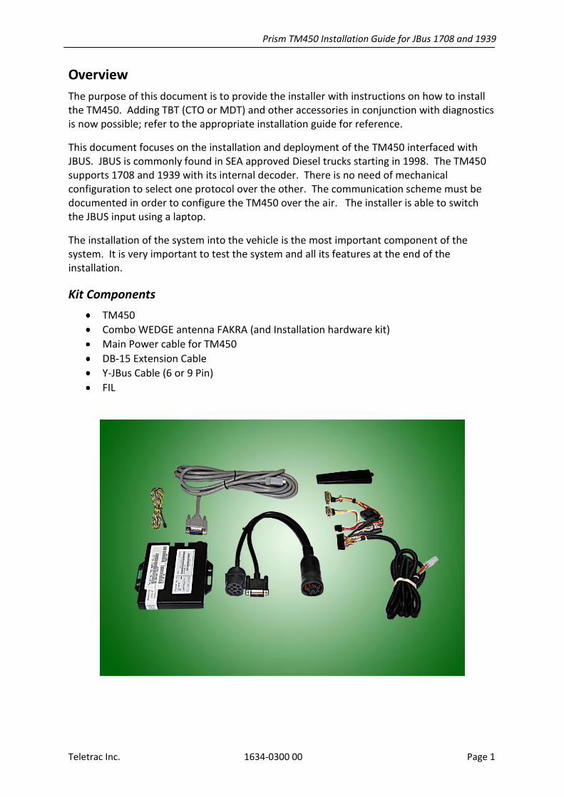
Kit Components
TM450
Combo WEDGE antenna FAKRA (and Installation hardware kit)
Main Power cable for TM450
DB-15 Extension Cable
Y-JBus Cable (6 or 9 Pin)
FIL

Prism TM450 Installation Guide for JBus 1708 and 1939
Teletrac Inc. 1634-0300 00 Page 2
Differences between the TM450 and the TM2J
The TM450 and the TM2J are very similar in basic appearance and basic functionality. There are two main differences;
1) The TM450 has FAKRA connectors for the antenna. This makes perfect antenna connections very simple and more reliable –no more lose or too tight connectors-. The connector features a locking mechanism that guarantees perfect connection every time.
2) The on-board connectors are Micro Fit. This is a smaller pitch connector, it frees up
valuable board space inside the TM450. The actual interface into the TM450 connector is exactly the same. The DB9 (MDT port) and DB15 (JBUS PORT) is
backwards compatible. No tools are ever required.
Prism TM450 Installation Guide for JBus 1708 and 1939
Teletrac Inc. 1634-0300 00 Page 3
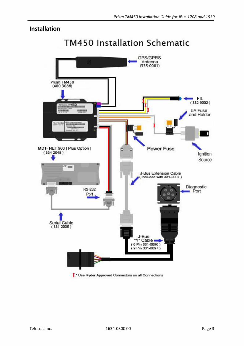
Installation
Prism TM450 Installation Guide for JBus 1708 and 1939
Teletrac Inc. 1634-0300 00 Page 4
Main Power Connections
The system is designed to receive power and ground via the JBUS connector. Only the Ignition wire is to be connected to a source of power. The ignition connection should be made to a source of power other than the Accessory.
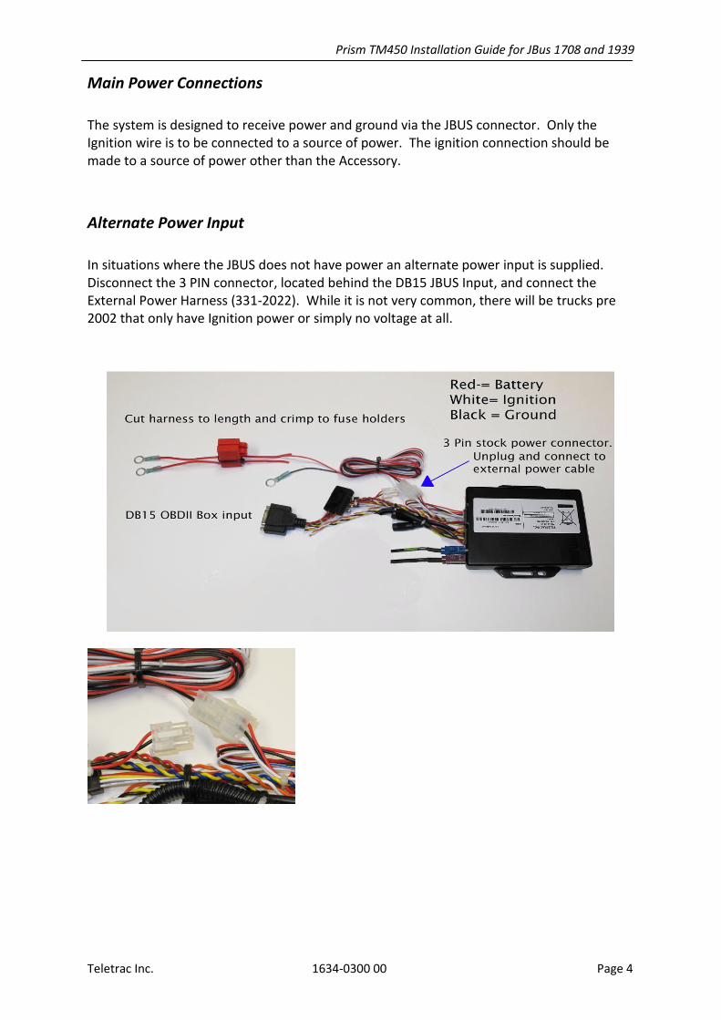
Alternate Power Input
In situations where the JBUS does not have power an alternate power input is supplied. Disconnect the 3 PIN connector, located behind the DB15 JBUS Input, and connect the External Power Harness (331-2022). While it is not very common, there will be trucks pre 2002 that only have Ignition power or simply no voltage at all.
Prism TM450 Installation Guide for JBus 1708 and 1939
Teletrac Inc. 1634-0300 00 Page 5
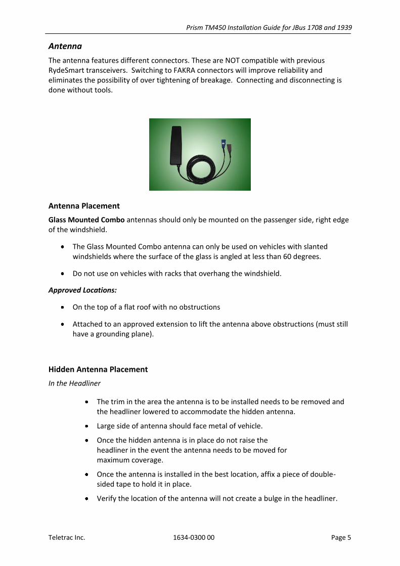
Antenna
The antenna features different connectors. These are NOT compatible with previous RydeSmart transceivers. Switching to FAKRA connectors will improve reliability and eliminates the possibility of over tightening of breakage. Connecting and disconnecting is done without tools.
Antenna Placement
Glass Mounted Combo antennas should only be mounted on the passenger side, right edge of the windshield.
The Glass Mounted Combo antenna can only be used on vehicles with slanted windshields where the surface of the glass is angled at less than 60 degrees.
Do not use on vehicles with racks that overhang the windshield.
Approved Locations:
On the top of a flat roof with no obstructions
Attached to an approved extension to lift the antenna above obstructions (must still have a grounding plane).
Hidden Antenna Placement
In the Headliner
The trim in the area the antenna is to be installed needs to be removed and the headliner lowered to accommodate the hidden antenna.
Large side of antenna should face metal of vehicle.
Once the hidden antenna is in place do not raise the headliner in the event the antenna needs to be moved for maximum coverage.
Once the antenna is installed in the best location, affix a piece of double-sided tape to hold it in place.
Verify the location of the antenna will not create a bulge in the headliner.

Prism TM450 Installation Guide for JBus 1708 and 1939
Teletrac Inc. 1634-0300 00 Page 6
In the Dashboard
Antenna should be placed as high as possible in the dash with a clear view out the windshield with no metallic obstructions.
Antenna must be secured in place to assure it does not move and degrade signal.
Test the antenna prior to putting everything back together because some dashboards are made with carbon composites that will deteriorate the signal strength.
Testing the Installation
Verifying that the installation is fully operational is the single most important part of the installation.
Before you start the Installation Test, turn the ignition to the On position for 1 minute, and then turn it back to Off.
Step 1: Once all power and antenna connections are complete, make sure the Transceiver is working properly. The easiest way to do this is using an MDT 955.
Press <Control 1> to Display Radio Status, Confirm Registration and RSSI (>105)
Confirm that the IP number displayed matches the paperwork.
Step 2: Press <Control 2> in the MDT to confirm that:
The number of satellites acquired is greater than 5, and
The SNR is greater than 33.
Confirm that date and time are valid (the time reflected will be GMT -5 to -8 hours of your local time).
Step 3: MUST be completed for an installation to be completed!
There are 2 possible ways to complete Step 3:
Option 1- Use the eClient software - Log into the customer’s account in eClient on your laptop or another computer, and confirm that the IP you are working with is in the customer’s account and is assigned to a vehicle.
Once you have done this, perform a locate on the vehicle to confirm that the vehicle responds.

Prism TM450 Installation Guide for JBus 1708 and 1939
Teletrac Inc. 1634-0300 00 Page 7
Option 2- Check the customer’s Detailed Report by logging into www.teletrac.net. Select the vehicle from the Vehicles selection and run a Detailed report. Verify that data is coming in from the unit.
For more information on using the Web Reporter see the eClient Training Guide or Help
Topics in eClient about “Creating Reports”.
**WARNINGS**
Installation is NOT complete unless all 3 of the above described steps are completed.
Testing with the MDT only is not acceptable.
Every repair or new installation must be tested following the three steps outlined
above to confirm proper operation.
Failure to complete all testing as described in this section (above) is considered a
serious offense and may result in disciplinary action up to and including termination.

Prism TM450 Installation Guide for JBus 1708 and 1939
Teletrac Inc. 1634-0300 00 Page 8
TM450 Hardware Information
Firmware Versions
MDT 960 CE; V09083138
CTO; 35.07 (NYR)
TM450 firmware TBT enabled; 5.0.143
Pin Assignments
(View looking in to connector)
Figure 2: Power/Data Interface (CON1)
1. RS232 Tx Output 2. RS232 Rx Input 3. Signal Ground 4. Ignition Sense (IGN) White 5. Power Ground (GND) Black 6. Positive Battery (VBATT) Red
(View looking in to connector)
Figure 1: Accessory Connector (CON2)
1. Microphone input (MIC IN-)
2 Normally high switch input (INHIGH) 3 Ground (GND)
4 Emergency switch input (ESW)
5 Relay driver output (RELAY2)
6 Smartnav switch input (TSW)
7 Relay driver output (RELAY1)
8 SAE J1708 bus A signal (J1708A)
9 CAN bus L signal (CANL)
10 Microphone input (MIC IN+)
11 Info switch input (ISW)
12 Ignition Sense (IGN)
13 Speaker output (SPK+)
14 Speaker output (SPK-)
15 Ground (GND)
16 Battery supply rail (VBATT)
17 SAE J1708 bus B signal (J1708B)
18 CAN bus H signal (CANH)
Prism TM450 Installation Guide for JBus 1708 and 1939
Teletrac Inc. 1634-0300 00 Page 9
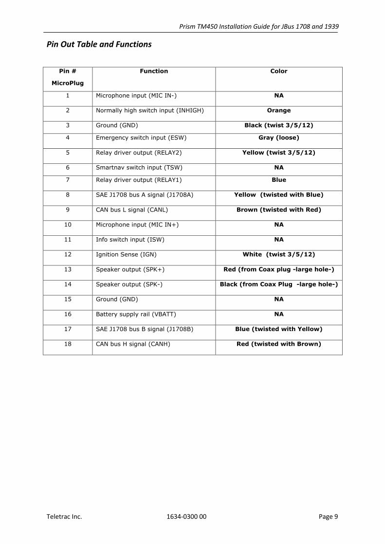
Pin Out Table and Functions
Pin #
MicroPlug
Function Color
1 Microphone input (MIC IN-) NA
2 Normally high switch input (INHIGH) Orange
3 Ground (GND) Black (twist 3/5/12)
4 Emergency switch input (ESW) Gray (loose)
5 Relay driver output (RELAY2) Yellow (twist 3/5/12)
6 Smartnav switch input (TSW) NA
7 Relay driver output (RELAY1) Blue
8 SAE J1708 bus A signal (J1708A) Yellow (twisted with Blue)
9 CAN bus L signal (CANL) Brown (twisted with Red)
10 Microphone input (MIC IN+) NA
11 Info switch input (ISW) NA
12 Ignition Sense (IGN) White (twist 3/5/12)
13 Speaker output (SPK+) Red (from Coax plug -large hole-)
14 Speaker output (SPK-) Black (from Coax Plug -large hole-)
15 Ground (GND) NA
16 Battery supply rail (VBATT) NA
17 SAE J1708 bus B signal (J1708B) Blue (twisted with Yellow)
18 CAN bus H signal (CANH) Red (twisted with Brown)

Teletrac Installer Work Sheet
Prior to calling Teletrac make sure that you have the following fields filled out.
Account Number____________________________ Date ________________
Customer Name –who is the vehicle for- ___________________________________
Installed By –tech name- ___________ Installation Company ______________
Vehicle Number ______________ VIN Number ________________________
Make and Model _______________Year ________License Plates___________
Teletrac Options Installed (JBUS, OBDII, PTO, MDT,etc). _________________
If installing OBDII record the Odometer mileage _________________
Affix the SIM, VIP, MIN sticker here.
Numbers to call
Calling for Activation and Test (714) 890 7656
Calling for expanded support (714) 552 8002 or (713) 359 8723
Fax the work sheets daily to (714) 379 6378.
Attention; HELP DESK.