private telecommunication networks (ptn) -...
TRANSCRIPT
Standard ECMA-1063rd Edi t ion - December 1993
S t a n d a r d i z i n g I n f o r ma t i o n a n d C o mmu n i c a t i o n S y s t e ms
Phone: +41 22 849.60.00 - Fax: +41 22 849.60.01 - URL: h t tp : / /www.ecma.ch - In ternet : he [email protected]
Private TelecommunicationNetworks (PTN) - SignallingProtocol at the S Reference Point- Circuit Mode Basic Services


Standard ECMA-1063rd Edi t ion - December 1993
S t a n d a r d i z i n g I n f o r ma t i o n a n d C o mmu n i c a t i o n S y s t e ms
Phone: +41 22 849.60.00 - Fax: +41 22 849.60.01 - URL: h t tp : / /www.ecma.ch - In ternet : he [email protected]
IW - ECMA-106.DOC - 16.11.95 16,57
Private TelecommunicationNetworks (PTN) - SignallingProtocol at the S Reference Point- Circuit Mode Basic Services(SSIG-BC)


Brief history
This Standard is one of a series of ECMA standards defining services and signalling protocols applicable to PrivateTelecommunication Networks (PTNs). The series uses the ISDN concepts as developed by the ITU-T and is also within theframework of standards for open systems interconnection as defined by ISO. It has been produced under ITSTC work items M-IT-05 4.3.1.1 and 4.4 for Bon de commande 75D.5.
This particular Standard defines the signalling protocol for use at the S reference point in support of basic circuit modeservices. It is intended to be supported by a suitable layer 2 protocol, for example Standard ECMA-105, in the D-channel of abasic access interface or a primary rate access interface.
The 1st Edition of Standard ECMA-106 was published by ECMA in 1985. A 2nd Edition was published by ECMA in June1991, to extend the scope to include the connection of all types of Terminal Equipment to Private TelecommunicationNetworks, instead of just the connection of Data Processing Equipment to Private Circuit-Switching Networks, and to reflectwork undeway in ETSI on the corresponding standard for public ISDNs in Europe.
The protocol defined in this 3rd Edition of Standard ECMA-106 is based upon that now specified in ETS 300 102-1. ETS 300102-1 is applicable to interfaces to public ISDNs at the T reference point, or at coincident S and T reference points if there isno NT2 function. This ECMA Standard references many of the clauses of ETS 300 102-1 to avoid reproducing large quantitiesof text. Some of the options in ETS 300 102-1 are not applicable to interfaces at the S reference point, and therefore areexcluded by this Standard. On the other hand, certain additions have been identified as being required at the S reference point.However, the major part of the protocol is identical with that specified in ETS 300 102-1, enabling TEs to be designed whichare compatible with both PTNs and public ISDNs and can therefore be connected to either.
This ECMA Standard refers to ETS 300 102-2 for the description of the protocol in SDL form.
Compared to the 2nd Edition of Standard ECMA-106, various changes have been made in order to achieve alignment withETS 300 192 (which is based on the 2nd Edition of ECMA-106 but modified during ETSI Public Enquiry and published byETSI in December 1992).
Further, this 3rd Edition of Standard ECMA-106 includes a PICS proforma (annex G), which has itself been forwarded to ETSIas a proposed Amendment to ETS 300 192.
This Standard is based upon the practical experience of ECMA member companies and the results of their active andcontinuous participation in the work of ISO/IEC JTC1, ITU-T, ETSI and other international, regional and nationalstandardization bodies. It represents a pragmatic and widely based consensus.
Adopted as 3rd Edition of Standard ECMA-106 by the General Assembly of December 1993.


- i -
Table of contents
Page
1 Scope 1
2 Conformance 1
3 References 1
4 Definitions 1
4.1 Basic call 1
4.2 Incoming call 1
4.3 Outgoing call 1
4.4 User and network 2
5 Acronyms 2
6 General principles 2
6.1 Protocol model 2
6.2 Services provided to call control 2
6.3 Services required of the Data Link Layer 3
6.3.1 Acknowledged information transfer services 3
6.3.2 Unacknowledged information transfer services 3
6.4 Protocol control states 3
6.4.1 States for circuit mode call control 3
6.4.2 States for layer management 4
6.5 Message segmentation and reassembly functions 4
6.5.1 Null (0) 5
6.5.2 Receiving segmented message (1) 5
7 General procedures 5
7.1 Use of the services of Layer 2 5
7.1.1 Establishment of a Data Link connection 5
7.1.2 Transfer of data 5
7.2 Message segmentation procedures 5
7.3 Handling of protocol error conditions 6
7.3.1 Addition to requirements of subclause 5.8.6.1 of ETS 300 102-1 6
7.3.2 Addition to requirements of subclause 5.8.6.2 of ETS 300 102-1 6
7.3.3 Modification to subclause 5.8.7.1, second paragraph, of ETS 300 102-1 6
7.3.4 Replacement for items a, b and c of subclause 5.8.7.1 of ETS 300 102-1 6
7.3.5 Addition to requirements of subclause 5.8.7.2 of ETS 300 102-1 6
7.3.6 Modification to subclause 5.8.7.2, first paragraph, of ETS 300 102-1 6
7.3.7 Modification to subclause 5.8.7.2, second paragraph, of ETS 300 102-1 6
7.4 Handling of configuration errors 6
- i i -
7.5 Status and status enquiry procedures 7
7.5.1 Modifications to subclause 5.8.10 of ETS 300 102-1 7
7.5.2 Modifications to subclause 5.8.11 of ETS 300 102-1 7
8 Procedures for circuit mode call control 7
8.1 Call establishment at the originating interface 7
8.1.1 Addition to subclause 5.1.1 of ETS 300 102-1 7
8.1.2 Modification to the "ETSI requirement" concerning en-bloc sending in subclause 5.1.1 of ETS 300 102-1 7
8.1.3 Modification to the "ETSI requirement" concerning the tone option in subclause 5.1.3 of ETS 300 102-1 7
8.1.4 Clarification of subclause 5.1.5 of ETS 300 102-1 8
8.1.5 Modification to subclause 5.1.6 of ETS 300 102-1 8
8.1.6 Modification to the "ETSI requirement" concerning the sending of the alerting message in subclause 5.1.7 ofETS 300 102-1 8
8.1.7 Modification to the "ETSI requirement" concerning the receipt of the alerting message in subclause 5.1.7 ofETS 300 102-1 8
8.1.8 Addition to subclause 5.1.8 of ETS 300 102-1 8
8.1.9 Non-applicability of transit network selection 8
8.2 Call establishment at the destination interface 8
8.2.1 Addition to subclause 5.2.1 of ETS 300 102-1 8
8.2.2 Change to case 4 of subclause 5.2.3.1 of ETS 300 102-1 8
8.2.3 Change to case b of subclause 5.2.3.2 of ETS 300 102-1 9
8.2.4 Non-applicability of overlap receiving procedure 9
8.2.5 Replacement of the first paragraph of 5.2.5.2 of ETS 300 102-1 9
8.2.6 Modification to the "ETSI requirement" concerning progress description value No. 1 9
8.2.7 Addition to subclause 5.2.8 of ETS 300 102-1 9
8.3 Call clearing 9
8.3.1 Replacement of item b of subclause 5.3.2 of ETS 300 102-1 9
8.3.2 Non-applicability of item c of subclause 5.3.2 of ETS 300 102-1 9
8.3.3 Modification to subclause 5.3.3 of ETS 300 102-1 9
8.3.4 Modification to subclause 5.3.4.1 of ETS 300 102-1 9
8.3.5 Modification to subclause 5.3.4.2 of ETS 300 102-1 9
8.4 In-band tones and announcements 9
8.5 Call collisions 9
8.6 Suspend and resume procedures 10
8.7 TE-side and PTN-side SDL diagrams 10
9 Procedures for layer management 10
9.1 Restart procedures 10
10 List of system parameters 10
11 Functional definition and content of messages 10
11.1 Messages for general procedures 12
11.1.1 STATUS 12
11.1.2 STATUS EQUIRY 12

- i i i -
11.2 Messages for circuit mode call control 12
11.2.1 ALERTING 12
11.2.2 CALL PROCEEDING 12
11.2.3 CONNECT 12
11.2.4 CONNECT ACKNOWLEDGE 13
11.2.5 DISCONNECT 13
11.2.6 INFORMATION 13
11.2.7 PROGRESS 13
11.2.8 RELEASE 13
11.2.9 RELEASE COMPLETE 13
11.2.10 RESUME 13
11.2.11 RESUME ACKNOWLEDGE 13
11.2.12 RESUME REJECT 13
11.2.13 SETUP 13
11.2.14 SETUP ACKNOWLEDGE 14
11.2.15 SUSPEND 14
11.2.16 SUSPEND ACKNOWLEDGE 14
11.2.17 SUSPEND REJECT 14
11.3 Messages for layer management 14
11.3.1 RESTART 14
11.3.2 RESTART ACKNOWLEDGE 14
12 General message format and coding of information elements 14
12.1 Overview 14
12.2 Protocol discriminator 14
12.3 Call reference 14
12.4 Message type 14
12.5 Other information elements (Codeset 0) 15
12.5.1 Coding rules 15
12.5.2 Extensions of codesets 16
12.5.3 Locking shift procedure 16
12.5.4 Non-locking shift procedure 17
12.5.5 Bearer capability 17
12.5.6 Call identity 17
12.5.7 Call state 17
12.5.8 Called party number 17
12.5.9 Called party subaddress 17
12.5.10 Calling party number 17
12.5.11 Calling party subaddress 17
12.5.12 Cause 18
12.5.13 Channel identification 18
12.5.14 Connected number 18
12.5.15 Connected subaddress 18
12.5.16 Date / time 19

- iv -
12.5.17 Display 19
12.5.18 High layer compatibility (Layers 4 - 7) 19
12.5.19 Low layer compatibility (Layers 1 - 3) 19
12.5.20 Progress indicator 19
12.5.21 Restart indicator 19
12.5.22 Segmented message 19
12.5.23 Sending complete 20
12.6 Information elements of codeset 5 20
12.6.1 Party category 20
Annex A (informative) Use of progress indicators 21
Annex B (informative) Use of cause values 23
Annex C (informative) Examples of message sequences 25
Annex D (informative) Manufacturer-specific information 31
Annex E (informative) Bibliography 33
Annex F (informative) Terminal interchangeability 35
Annex G (normative) Protocol Implementation Conformance Statement (PICS) Proforma 37

1 ScopeThis Standard defines the Layer 3 protocol for signalling for the support of circuit-mode bearer services (used either ontheir own or in support of teleservices) at an interface at the S reference point between a Terminal Equipment (TE) anda Private Telecommunication Network (PTN). The S reference point is defined in ENV 41004.
This Standard is based upon ETS 300 102-1, which defines the equivalent protocol for the T and coincident T and Sreference points between a user and a public ISDN. Many of the clauses of ETS 300 102-1 are incorporated byreference. Any reference in the text of ETS 300 102-1 to annex D of that document are not applicable to this Standard.Annex F contains information on terminal interchangeability between PTNs and public ISDNs.
This Standard is applicable to basic and primary rate accesses of PTNXs and to TEs that are intended for connection tosuch accesses.
The conveyance of non-standardized (e.g. manufacturer-specific) information in messages is outside the scope of thisStandard. Annex D discusses ways in which this can be achieved.
2 ConformanceIn order to conform to this Standard, a PTNX shall satisfy the PTN requirements and a TE shall satisfy the TErequirements identified in the Protocol Implementation Conformance Statement (PICS) Proforma in annex G.
3 ReferencesECMA-105 Private Telecommunication Networks (PTN) - Signalling at the S Reference Point - Data Link
Layer Protocol (SSIG-L2) (1993)
ECMA-155 Addressing in Private Telecommunication Networks (1991)
ETS 300 102-1 Integrated Services Digital Network (ISDN); User-network interface layer 3; Specifications forbasic call control (1990)
ETS 300 171 Private Telecommunication Network (PTN); Specification, functional models and informationflows; Control aspects of circuit-mode basic services (1992)
ETS 300 189 Private Telecommunication Network (PTN); Addressing (1992)
ENV 41004 Reference configurations for calls through exchanges of private telecommunication networks(1989)
ENV 41005 Method for the specification of basic and supplementary services of private telecommunicationnetworks (1990)
ENV 41007 Definition of terms in private telecommunication networks (1989)
CCITT Rec. I.112 Vocabulary of terms for ISDNs (1988)
4 DefinitionsFor the purpose of this Standard, the terminology defined in ENV 41007 and CCITT Rec. I.112 applies. If there isconflict, the definitions in ENV 41007 shall take precedence. In addition the following definitions apply.
4.1 Basic call
A single invocation of a basic service according to ETS 300 171.
4.2 Incoming call
A call presented to the TE by the PTN.
4.3 Outgoing call
A call presented to the PTN by the TE.

- 2 -
4.4 User and network
Throughout this Standard, reference is made to clauses in ETS 300 102-1. When applying a clause in ETS 300 102-1 to the TE-PTN interface, the term "user" shall be interpreted as "TE", and the term "network" shall be interpretedas "PTN".
5 AcronymsCLIP Calling Line Identification PresentationCOLP Connected Line Identification PresentationISDN Integrated Services Digital NetworkMSI Manufacturer-Specific InformationPICS Protocol Implementation Conformance StatementPTN Private Telecommunication NetworkPTNX Private Telecommunication Network eXchangeSAP Service Access PointTE Terminal Equipment
6 General principlesThis Standard specifies the signalling procedures for establishing, maintaining and clearing a basic circuit-switchedcall at a PTN user access. These signalling procedures are defined in terms of messages exchanged over a data linkconnection on the D-channel of a basic or primary rate interface structure. The result of successful basic callestablishment is a connection for the purpose of user information transfer. This connection uses a B-channel of a basicor primary rate interface structure.
Throughout this Standard, the term "B-channel" is used to indicate any channel other than the D-channel.
The basic call signalling procedures specified in this Standard apply to circuit mode bearer services, used either ontheir own or in support of teleservices.
In addition, this Standard includes signalling procedures for layer management, including restart.
6.1 Protocol model
Figure 1 shows the relationship, within the Control Plane, between the layer 3 protocol at the S reference point, theprotocol entities in the TE and PTN, and the adjacent layers.
The Protocol Control entity provides services to Call Control. Call Control corresponds to the functional entitiesidentified for the basic call at Stage 2 (see ETS 300 171), i.e. the Call Control functional entity within the PTN(PTNX) and the Call Control Agent functional entity within the TE. Primitives exchanged across the boundarybetween Call Control and Protocol Control correspond to the information flows exchanged between the Call Controland Call Control Agent functional entities, as identified at Stage 2. Protocol Control provides the mapping betweenthese primitives and the messages transferred across the TE-PTN interface.
In order to transfer messages, Protocol Control uses the services of the Data Link Layer, as available at the DataLink Layer Service Access Point (SAP). The Data Link Layer in turn uses the services of the Physical Layer.
6.2 Services provided to call control
Protocol Control provides services to Call Control whereby Call Control can send information flows to and receiveinformation flows from the peer Call Control. A primitive from Call Control to Protocol Control of type "request" or"response" normally results in the associated information flow being presented to the peer Call Control as aprimitive of type "indication" or "confirmation" respectively.
PTN side primitives are as listed in subclause 5.3 of ETS 300 102-2. TE side primitives are as listed in subclause6.3 of ETS 300 102-2.
NOTE 1
These primitive names differ from the information flow names specified at Stage 2 in ETS 300 171.

- 3 -
. ECMA-94-0043-A
TE
CALL
CONTROL
PROTOCOLCONTROL
LAYER 2
LAYER 1
CALL
CONTROL
PROTOCOL
CONTROL
LAYER 2
LAYER 1
PTN
INTERFACE
TE-PTN
LAYER 3
PROTOCOL
LAYER 2 SERVICE
ACCESS POINT
Figure 1 - Protocol model
6.3 Services required of the Data Link Layer
Services provided by the Data Link Layer and the associated primitives are defined in Standard ECMA-105.Protocol Control uses the following services:
6.3.1 Acknowledged information transfer services
− Data Transfer, using the DL-DATA-REQUEST/INDICATION primitives;
− Establishment of Multiple Frame Operation, using theDL-ESTABLISH-REQUEST/INDICATION/CONFIRM primitives;
− Termination of Multiple Frame Operation, using the DL-RELEASE-REQUEST/INDICATION/CONFIRMprimitives.
6.3.2 Unacknowledged information transfer services
− Data Transfer, using the DL-UNIT-DATA-REQUEST/INDICATION primitives.
6.4 Protocol control states
Protocol Control procedures for calls and layer management are specified in terms of:
− messages which are transferred across the TE-PTN interface;
− the primitives to and from Call Control at the TE side and the PTN side of the TE-PTN interface;
− the information processing and actions that take place within Protocol Control at the TE side and the PTN sideof the TE-PTN interface; and
− the states that can exist within Protocol Control at the TE side and the PTN side of the TE-PTN interface.
State machines are deemed to exist for each circuit mode call. A further state machine is deemed to exist for layermanagement, covering restart procedures.
6.4.1 States for circuit mode call control
The call states defined in subclause 2.1.1 of ETS 300 102-1 for the user side of the user-network interface applyalso to the TE side of the TE-PTN interface.

- 4 -
NOTE 2
If the TE does not support the optional suspend and resume procedures of subclause 8.6, states U15 and U17will never be entered.
The call states defined in subclause 2.1.2 of ETS 300 102-1 for the network side of the user-network interfaceapply also to the PTN side of the TE-PTN interface.
NOTE 3
If the PTN does not support the optional suspend and resume procedures of subclause 8.6, states N15 and N17will never be entered.
6.4.2 States for layer management
The states defined in subclause 2.4.1 of ETS 300 102-1 for use in association with the global call reference at theuser side of the user-network interface apply also to the TE side of the TE-PTN interface.
The states defined in subclause 2.4.2 of ETS 300 102-1 for use in association with the global call reference at thenetwork side of the user-network interface apply also to the PTN side of the TE-PTN interface.
6.5 Message segmentation and reassembly functions
Message segmentation and reassembly functions are employed where the size of a message exceeds the maximumsize of the Data Link Layer information field size. The architectural relationship of segmentation and reassemblyfunctions to other Protocol Control functions is shown in figure 2.
ECMA-94-0044-A
CALL CONTROL
SEGMENTATIONAND REASSEMBLY
FUNCTIONS
PROTOCOLDISCRIMINATOR
FILTER
OTHER FUNCTIONS
PROTOCOLCONTROL
DATA LINK LAYER
Figure 2 - Logical architecture of Protocol Control showing segmentation and reassembly functions
Segmentation and reassembly, where provided, effectively constitutes a lower sub-layer of Protocol Control. Theonly function of Protocol Control which lies below the segmentation and reassembly functions is the filtering out ofmessages containing a protocol discriminator which is not in accordance with that specified.
The primitives across the boundary between segmentation and reassembly functions and other functions are thesame as those between the Data Link Layer and Protocol Control. The segmentation functions act upon DL-DATA-REQUEST primitives by converting, where necessary, a single primitive into two or more primitives beforepassing to the Data Link Layer. The reassembly functions act upon DL-DATA-INDICATION primitives from theData Link Layer by converting, where necessary, two or more primitives into a single primitive for passing up to theother functions of Protocol Control. Other primitives to and from the Data Link Layer are not affected by thesegmentation and reassembly functions.

- 5 -
Message segmentation and reassembly procedures are each specified in terms of a state machine. Messagesegmentation uses a single state, Null (0). Message reassembly uses two states, as listed below.
6.5.1 Null (0)
No message is being reassembled.
6.5.2 Receiving segmented message (1)
One or more segments of a segmented message have been received and one or more further segments areawaited.
7 General procedures7.1 Use of the services of Layer 2
7.1.1 Establishment of a Data Link connection
Before the procedures for call control, layer management or any of the general procedures in subclauses 7.2 to7.4 can be performed, a Data Link connection must be established between the PTN and the TE. The exception isthe sending of a SETUP message by the PTN using the unacknowledged information transfer service of the DataLink Layer.
If a Data Link connection has not already been established, Protocol Control can request establishment bysending a DL-ESTABLISH-REQUEST primitive to the Data Link Layer. Receipt of a DL-ESTABLISH-CONFIRMATION primitive or a DL-ESTABLISH-INDICATION primitive from the Data Link Layer indicatesthat a Data Link connection has been established.
7.1.2 Transfer of data
If a multi-point configuration exists at an interface, or if the PTN does not know whether the configuration ismulti-point or point-to-point, a SETUP message sent by the PTN shall use the unacknowledged data transferservice (broadcast Data Link) of the Data Link Layer. A message (or message segment) shall be transmitted byincluding it within a DL-UNIT-DATA-REQUEST primitive to the Data Link Layer. A received message (ormessage segment) will appear included with a DL-UNIT-DATA-INDICATION primitive from the Data LinkLayer.
All other messages shall use the acknowledged data transfer service of the Data Link Layer (point-to-point DataLink). A message (or message segment) shall be transmitted by including it with a DL-DATA-REQUESTprimitive to the Data Link Layer. A received message (or message segment) will appear included within a DL-DATA-INDICATION primitive from the Data Link Layer.
NOTE 4
Before a TE can respond to a SETUP message delivered using the unacknowledged data transfer service, it mustestablish a Data Link connection according to the procedures of 7.1.1, unless a Data Link connection alreadyexists between the PTN and that TE.
7.2 Message segmentation procedures
This subclause specifies message segmentation and reassembly procedures for messages whose length exceeds themaximum size of the Data Link Layer information field. The maximum Data Link Layer information field size isdefined in ETS 300 169 (parameter N201).
A PTN or a TE conforms to the message segmentation procedures if it is capable of transmitting a message whichexceeds the maximum size of the Data Link Layer information field. Segmentation procedures shall not be appliedto messages which do not exceed the maximum size of the Data Link Layer information field.
A PTN or a TE which claims conformance to this Standard shall declare the maximum size of message which it isable to receive. The declared maximum size shall not be less than 260 octets. If the maximum size of the Data LinkLayer information field is less than the declared maximum size of message which can be received, the PTN or TEshall conform to the message reassembly procedures.
The message segmentation and reassembly procedures of annex K of ETS 300 102-1 shall apply, except therequirement in clause K.1.
If a segmented message is received by a PTN or TE which does not support reassembly procedures, the proceduresspecified in subclause 5.8.4 of ETS 300 102-1 for message type errors shall apply to each received segment.

- 6 -
7.3 Handling of protocol error conditions
The requirements of subclauses 5.8.1 to 5.8.9 of ETS 300 102-1 shall apply with the following clarifications andadditions.
7.3.1 Addition to requirements of subclause 5.8.6.1 of ETS 300 102-1
When a RELEASE message which contains no Cause information element is received as a first clearing message,the actions to be taken shall be the same as if a RELEASE message with Cause No. 31 "normal, unspecified" hadbeen received, except that if a RELEASE COMPLETE message is sent, it shall contain Cause No. 96 "mandatoryinformation element is missing".
7.3.2 Addition to requirements of subclause 5.8.6.2 of ETS 300 102-1
When a RELEASE message with invalid content of the Cause information element is received as a first clearingmessage, the actions to be taken shall be the same as if a RELEASE message with Cause No. 31 "normal,unspecified" had been received, except that if a RELEASE COMPLETE message is sent, it shall contain CauseNo. 100 "invalid information element contents".
7.3.3 Modification to subclause 5.8.7.1, second paragraph, of ETS 300 102-1
When the unrecognized information element occurs in a message other than DISCONNECT, RELEASE, orRELEASE COMPLETE, the STATUS message, if sent, shall indicate the call state that the receiving entityenters after processing the message in which the unrecognized information element was received.
7.3.4 Replacement for items a, b and c of subclause 5.8.7.1 of ETS 300 102-1
a) When a DISCONNECT message is received which has one or more unrecognized information elements,the actions taken shall be the same as if a DISCONNECT message had been received without theseunrecognized information elements with the exception that the RELEASE message returned shall containCause No. 99 "information element non-existent". It is recommended to provide Cause No. 99 withdiagnostics, although the inclusion of diagnostics is optional.
b) When a RELEASE message is received which has one or more unrecognized information elements, theactions taken shall be the same as if a RELEASE message had been received without these unrecognizedinformation elements with the exception that the RELEASE COMPLETE message returned shall containCause No. 99 "information element non-existent". It is recommended to provide Cause No. 99 withdiagnostics, although the inclusion of diagnostics is optional.
c) When a RELEASE COMPLETE message is received which has one or more unrecognized informationelements, the actions taken shall be the same as if a RELEASE COMPLETE message without theseunrecognized information elements had been received.
7.3.5 Addition to requirements of subclause 5.8.7.2 of ETS 300 102-1
If a DISCONNECT, RELEASE or RELEASE COMPLETE message is received which has one or more non-mandatory information elements with invalid contents, normal call clearing shall apply. The RELEASE andRELEASE COMPLETE messages returned shall contain Cause No. 100 "invalid information element contents".It is recommended to provide Cause No. 100 with diagnostics, although the inclusion of diagnostics is optional.
7.3.6 Modification to subclause 5.8.7.2, first paragraph, of ETS 300 102-1
When the information element with content error occurs in a message other than DISCONNECT, RELEASE, orRELEASE COMPLETE, the STATUS message, if sent, shall indicate the call state that the receiving entityenters after processing the message in which the information element with content error was received.
7.3.7 Modification to subclause 5.8.7.2, second paragraph, of ETS 300 102-1
Access information elements with a length exceeding the maximum length shall be treated as having contenterror, i.e. they shall not be truncated and processed.
7.4 Handling of configuration errors
In point-to-multipoint configurations at the TE-PTN interface, the PTN capability may be limited by manufacturerdeclaration. This means that the PTN may accept only a limited number of positive responses to a SETUP messagewhich was delivered using the broadcast data link. If the number of positively responding TEs, as defined by thedata link on which an initial responding message (i.e. CALL PROCEEDING, ALERTING or CONNECT) isreceived, reaches the limit, any additional positive response shall be rejected. Depending on implementation, the

- 7 -
PTN shall either send a RELEASE COMPLETE message containing Cause No. 47 "Resource unavailable,unspecified" or initiate normal call clearing using the same Cause number.
NOTE 5
It is the user's responsibility to configure a basic access in accordance with the particular PTN's limitation.
7.5 Status and status enquiry procedures
The requirements of subclauses 5.8.10 to 5.8.11 of ETS 300 102-1 shall apply with the following amendments.
7.5.1 Modifications to subclause 5.8.10 of ETS 300 102-1
The requirements of the paragraph beginning with "The sending or receipt of the STATUS ENQUIRYmessage..." shall be modified as follows.
A STATUS message containing Cause No. 97 shall not be treated as a response to the STATUS ENQUIRYmessage.
7.5.2 Modifications to subclause 5.8.11 of ETS 300 102-1
The requirements of the paragraph beginning with "A STATUS message may be received..." and the paragraphbeginning with "In this case the actions..." shall be replaced by the following.
On receipt of a STATUS message indicating a compatible protocol control state butcontaining one of the Causes No. 96, No. 97, No. 99, or No. 100, the receiving entity shouldattempt to analyse the contents of the received STATUS message considering the currentstage of the call in order to determine whether or not the call can continue. The actions to betaken are an implementation option.
8 Procedures for circuit mode call controlThe call states referred to in this clause cover the states perceived by the PTN, states perceived by the TE and stateswhich are common to both TE and PTN. Unless specifically qualified, all states described in the following text shall beunderstood as common.
As a general principle, any message sent by the PTN to the TE may contain a Display information element whosecontents may be displayed by the TE.
In addition to the messages exchanged as described in the following subclauses, INFORMATION messages for callcontrol may be sent by the TE or by the PTN only after the first response to a SETUP message has been sent orreceived, and before clearing of the call reference is initiated. An INFORMATION message received in the ReleaseRequest state may be ignored.
8.1 Call establishment at the originating interface
The requirements of subclause 5.1 of ETS 300 102-1 shall apply with the following additions and modifications.
8.1.1 Addition to subclause 5.1.1 of ETS 300 102-1
Address information elements shall be handled as specified in ETS 300 189.
8.1.2 Modification to the "ETSI requirement" concerning en-bloc sending in subclause 5.1.1 of ETS 300 102-1
The #-character shall not be used as sending complete indication.
8.1.3 Modification to the "ETSI requirement" concerning the tone option in subclause 5.1.3 of ETS 300 102-1
If the PTN provides dial tone to the TE, the progress description value No. 8 shall be included in the SETUPACKNOWLEDGE message. The "tone option" should be interpreted as the need to return dial tone in the casewhere the Bearer capability information element indicates an appropriate Bearer capability, e.g. "3,1 kHz audio"or "speech". The TE may attach to the B-channel on receipt of the SETUP ACKNOWLEDGE message with theProgress description value No. 8.

- 8 -
NOTE 6
The attachment to the B-channel by the TE at this point is recommended, when the network-provided tones orannouncements are of use.
8.1.4 Clarification of subclause 5.1.5 of ETS 300 102-1
The indicated Causes in subclause 5.1.5 of ETS 300 102-1 for rejecting a call because the requested service isnot authorized or is not available, are only examples. Other Causes are possible in this case.
8.1.5 Modification to subclause 5.1.6 of ETS 300 102-1
The requirements in subclause 5.1.6 of ETS 300 102-1 for receipt of a Progress indicator information elementshall be replaced by the following requirement.
If the Progress indication information element is included in a call control message, theprocedures specified in the rest of subclause 5.1 shall apply. If the Progress indicatorinformation element is included in the PROGRESS message, no state change shall occur butsupervisory timer T310 shall be stopped if progress description value No. 1, 2 or 8 isincluded in the PROGRESS message. In both cases the user shall connect to the B-channel (ifnot already connected) if progress description value No. 1 or 8 is included.
8.1.6 Modification to the "ETSI requirement" concerning the sending of the alerting message in subclause 5.1.7of ETS 300 102-1
The first "ETSI Requirement" in subclause 5.1.7 of ETS 300 102-1 concerning the sending of the ALERTINGmessage shall be replaced by the following requirement.
For services which require an in-band tone or announcement to be supplied to the calling TEduring the period of alerting, the PTN shall connect the appropriate tone or announcement tothe B-channel.
8.1.7 Modification to the "ETSI requirement" concerning the receipt of the alerting message in subclause 5.1.7of ETS 300 102-1
The second "ETSI Requirement" in subclause 5.1.7 of ETS 300 102-1 concerning the receipt of the ALERTINGmessage shall be replaced by the following requirement.
When the TE receives the ALERTING message with Progress description value No. 1 or No.8 of the Progress indicator information element included in the message, the TE may attach tothe B-channel (if not attached already). The TE shall attach to the B-channel on receipt of theCONNECT message if not already attached.
8.1.8 Addition to subclause 5.1.8 of ETS 300 102-1
The PTN shall support the transfer of the Low layer compatibility information element transparently in bothdirections in the SETUP and the CONNECT message if it is provided by the calling TE (using the SETUPmessage) or by the called TE (using the CONNECT message). The requirements of annex M and of annex L,clauses L.1 and L.2, of ETS 300 102-1 shall apply.
8.1.9 Non-applicability of transit network selection
The transit network selection, described in subclause 5.1.10 of ETS 300 102-1, is outside the scope of thisStandard.
8.2 Call establishment at the destination interface
The requirements of subclause 5.2 of ETS 300 102-1 shall apply with the following modifications.
8.2.1 Addition to subclause 5.2.1 of ETS 300 102-1
Address information elements shall be handled as specified in ETS 300 189.
8.2.2 Change to case 4 of subclause 5.2.3.1 of ETS 300 102-1
In case 4 "no B-channel available" of the channel selection procedure, the TE shall be allowed to reject the callby sending a RELEASE COMPLETE message with the Cause No. 34 (free TE) or No. 17 (busy TE). Alternativeactions whereby the user employs supplementary services in order to proceed with the call are outside the scopeof this Standard.

- 9 -
8.2.3 Change to case b of subclause 5.2.3.2 of ETS 300 102-1
In case b "no B-channel available" of the channel selection procedure, the TE shall be allowed to reject the callby sending a RELEASE COMPLETE message with the Cause No. 34 (free TE) or No. 17 (busy TE). Alternativeactions whereby the user employs supplementary services in order to proceed with the call are outside the scopeof this Standard.
8.2.4 Non-applicability of overlap receiving procedure
The overlap receiving procedure described in subclauses 5.2.1 and 5.2.4 of ETS 300 102-1 shall not be used, butonly the en-bloc receiving procedure. Complete called party number information shall always be sent in theSETUP message.
8.2.5 Replacement of the first paragraph of 5.2.5.2 of ETS 300 102-1
When the SETUP message is delivered on a broadcast data link, the PTN shall maintain a state machine thattracks the overall progression of the incoming call. The PTN shall also maintain an associated call state, up to animplementation-dependent number, for each responding TE as determined by the data link on which a message isreceived.
8.2.6 Modification to the "ETSI requirement" concerning progress description value No. 1
On receipt of a PROGRESS message with the Progress description value No. 1, the PTN shall stop onlysupervisory timer T310.
8.2.7 Addition to subclause 5.2.8 of ETS 300 102-1
The PTN shall support the transfer of the Low layer compatibility information element transparently in bothdirections in the SETUP and the CONNECT message if it is provided by the calling TE (using the SETUPmessage) or by the called TE (using the CONNECT message). The requirements of annex M and of annex L,clauses L.1 and L.2, of ETS 300 102-1 shall apply.
The PTN shall connect the B-channel in both directions on receipt of the CONNECT message from the calledTE. Optionally, and if the SETUP message was delivered on a point-to-point Data Link, through connection mayoccur in one or both directions at an earlier stage, but not before completion of channel negotiation at thedestination interface.
8.3 Call clearing
The requirements of subclause 5.3 of ETS 300 102-1 shall apply with the following amendments.
8.3.1 Replacement of item b of subclause 5.3.2 of ETS 300 102-1
If a SETUP message has been delivered on the broadcast data link, the PTN shall initiate the clearing of aresponding TE which is not awarded the call by sending a RELEASE message or, if the PTN is unable toestablish a state machine for the TE, by sending a RELEASE COMPLETE message. The RELEASE orRELEASE COMPLETE message shall contain cause No. 26 "non-selected user clearing".
8.3.2 Non-applicability of item c of subclause 5.3.2 of ETS 300 102-1
Subclause 5.3.2 of ETS 300 102-1 item c) shall not apply.
8.3.3 Modification to subclause 5.3.3 of ETS 300 102-1
A second Cause information element shall not be used in a clearing message.
8.3.4 Modification to subclause 5.3.4.1 of ETS 300 102-1
A second Cause information element shall not be used in a clearing message.
8.3.5 Modification to subclause 5.3.4.2 of ETS 300 102-1
A second Cause information element shall not be used in a clearing message.
8.4 In-band tones and announcements
The requirements of subclause 5.4 of ETS 300 102-1 shall apply with the exception of its Note 3.
8.5 Call collisions
The requirements of subclause 5.7 of ETS 300 102-1 shall apply.

- 10 -
8.6 Suspend and resume procedures
These procedures are optional for TEs and for PTNs.
The requirements of subclause 5.6 of ETS 300 102-1 shall apply with the following exceptions.
i. The "ETSI requirement" permitting some networks only to support a maximum length of the Call identity valueof two octets shall not apply.
ii. Subclause 5.6.7 shall not apply.
iii. The sending of the NOTIFY message is outside the scope of this Standard.
NOTE 7
The use of these procedures in support of the Terminal Portability supplementary service is outside the scope of thisStandard.
8.7 TE-side and PTN-side SDL diagrams
The user-side and network-side Specification and Description Language (SDL) diagrams contained in ETS 300 102-2 may also be used to provide additional clarification of the procedures described in this Standard, except for thoseaspects which conflict with differences between this Standard and ETS 300 102-1. The differences specified insubclauses 7.4, 7.5, 8.1.5, 8.2.2, 8.2.3, 8.2.4 and 8.3.2 of this Standard are not reflected in the SDL diagrams ofETS 300 102-2.
9 Procedures for layer management9.1 Restart procedures
The requirements of subclause 5.5 of ETS 300 102-1 shall apply.
ETS 300 102-2 contains (informative) SDL diagrams of the Restart procedures, which may be used to provideadditional clarification of these procedures.
10 List of system parametersThe requirements of clause 9 of ETS 300 102-1 shall apply with the following amendments.
i. All TE-side timer values shall have a tolerance of 5%; all PTN-side timer values shall have a tolerance of 10%.
ii. TE-side timer T310 shall have a value in the range 30 s to 120 s.
NOTE 8
It is recommended that, if TE-side timer T310 is implemented, a value near to the upper-end of the range bechosen to avoid problems when routeing is delayed, e.g. while waiting for resources.
iii. Timer T320 and timer T321 are not used.
11 Functional definition and content of messagesThe procedures of this Standard make use of the messages listed in table 1 below.

- 11 -
Table 1 - Messages
Call establishment messages:
ALERTINGCALL PROCEEDINGCONNECTCONNECT ACKNOWLEDGEPROGRESSSETUPSETUP ACKNOWLEDGE
Call information phase messages:
RESUMERESUME ACKNOWLEDGERESUME REJECTSUSPENDSUSPEND AKCNOWLEDGESUSPEND REJECT
Call clearing messages:
DISCONNECTRELEASERELEASE COMPLETE
Layer management messages:
RESTARTRESTART ACKNOWLEDGE
Miscellaneous messages:
INFORMATIONSTATUSSTATUS ENQUIRY
This clause defines each of these messages by means of a reference to the corresponding clause of ETS 300 102-1which describes the particular message, supplemented by a description of the differences in those cases where thisStandard differs from ETS 300 102-1.
Each definition in ETS 300 102-1 includes:
a) A brief description of the direction, significance and use of that message.
Statements in ETS 300 102-1 concerning the significance of a message shall be ignored.
b) A table listing the information elements of codeset 0 in the order of their appearance in the message (samerelative order for all message types). For each information element the table indicates:
− the clause of ETS 300 102-1 describing the information element (clause 12 below defines all theinformation elements used for this Standard);
− the direction in which it may be sent ['n → u', meaning network-to-user (PTN-to-TE); 'u → n', meaning user-to-network (TE-to-PTN) or both];
− whether inclusion is mandatory (M) or optional (O), with a reference to notes explaining the circumstancesunder which the information element shall be included;
− the length (or length range) of the information element, in octets, where * denotes an undefined maximumlength which may be network- or service- dependent.

- 12 -
c) Further explanatory notes, as necessary.
Additional elements in codeset 5 are specified in this Standard. Note, however, that the shift from codeset 0 to codeset5 is not explicitly shown.
Since this Standard only deals with basic call control, all messages and information elements of ETS 300 102-1 that donot pertain to basic services as defined in ETS 300 171 are excluded from its scope. This means that support of thesemessages and information elements is not required in order to conform to this Standard.
NOTE 9
Other messages and information elements than those defined here will be required for the support of supplementaryservices and Additional Network Features (ANFs); these will be defined in other standards.
11.1 Messages for general procedures
11.1.1 STATUS
The requirements of subclause 3.1.18 and of subclause 3.4.3 of ETS 300 102-1 shall apply.
11.1.2 STATUS EQUIRY
The requirements of subclause 3.1.19 of ETS 300 102-1 shall apply.
11.2 Messages for circuit mode call control
11.2.1 ALERTING
The requirements of subclause 3.1.1 of ETS 300 102-1 shall apply, with the following modifications:
− the information elements 'Facility' and 'User-user' are outside the scope of this Standard;
− the last statement of note 2, explaining the use of 'Progress indicator' in the direction 'user to network', shallnot apply since annex N is not applicable;
− the following codeset 5 information element may also be included:
Table 2 - Information element of codeset 5
Information Element Reference Direction Type Length
Party category 12.6 n → u 0 4
11.2.2 CALL PROCEEDING
The requirements of subclause 3.1.2 of ETS 300 102-1 shall apply, with the following exception:
− the last statement of note 3, explaining the use of 'Progress indicator' in the direction 'user to network', shallnot apply since annex N is not applicable.
11.2.3 CONNECT
The requirements of subclause 3.1.4 of ETS 300 102-1 shall apply, with the following modifications:
− the information elements 'Facility' and 'User-user' are outside the scope of this Standard;
− the following information elements may also be included:
Table 3 - Additional information elements
Information Element Reference Direction Type Length
Connected number 12.5 u → n (Notes 10 and 11) 0 4-24
Connected subaddress 12.5 u → n (Note 10) 0 4-23
Party category 12.6 n → u 0 4

- 13 -
NOTE 10
Inclusion in the direction user-to-network shall be in accordance with the provisions of ETS 300 189. Inclusionin the direction network-to-user is part of the supplementary service COLP.
NOTE 11
Information element Connected number is relevant only in the context of a multiple subscriber numberarrangement at the access.
11.2.4 CONNECT ACKNOWLEDGE
The requirements of subclause 3.1.5 of ETS 300 102-1 shall apply.
11.2.5 DISCONNECT
The requirements of subclause 3.1.6 of ETS 300 102-1 shall apply, with the following exception:
− the information elements 'Facility' and 'User-user' are outside the scope of this Standard.
11.2.6 INFORMATION
The requirements of subclause 3.1.8 of ETS 300 102-1 shall apply, with the following exceptions:
− the information element 'Keypad facility' is outside the scope of this Standard;
− the network option 'Inclusion of the 'Cause' information element' shall not apply.
11.2.7 PROGRESS
The requirements of subclause 3.1.10 of ETS 300 102-1 shall apply, with the following exception:
− the information element 'User-user' is outside the scope of this Standard.
11.2.8 RELEASE
The requirements of subclause 3.1.11 of ETS 300 102-1 shall apply, with the following exception:
− the information elements 'Facility' and 'User-user' are outside the scope of this Standard.
11.2.9 RELEASE COMPLETE
The requirements of subclause 3.1.12 of ETS 300 102-1 shall apply, with the following exception:
− the information elements 'Facility' and 'User-user' are outside the scope of this Standard.
11.2.10 RESUME
The requirements of subclause 3.1.13 of ETS 300 102-1 shall apply.
11.2.11 RESUME ACKNOWLEDGE
The requirements of subclause 3.1.14 of ETS 300 102-1 shall apply.
11.2.12 RESUME REJECT
The requirements of subclause 3.1.15 of ETS 300 102-1 shall apply.
11.2.13 SETUP
The requirements of subclause 3.1.16 of ETS 300 102-1 shall apply, with the following modifications:
− The information elements 'Facility', 'Keypad facility', 'Network specific facilities', 'Transit network selection'and 'User-user' are outside the scope of this Standard.
− The information element 'Progress indicator' shall be used only to indicate interworking.
− The information elements 'Calling party number' and 'Calling party subaddress' may optionally be included inthe direction user-to-network, in accordance with the provisions of ETS 300 189. Information elementCalling party number is relevant only in the context of a multiple subscriber number arrangement at theaccess.
NOTE 12
Inclusion in the direction network-to-user is part of the supplementary service CLIP.
− The following codeset 5 information element may also be included:
- 14 -
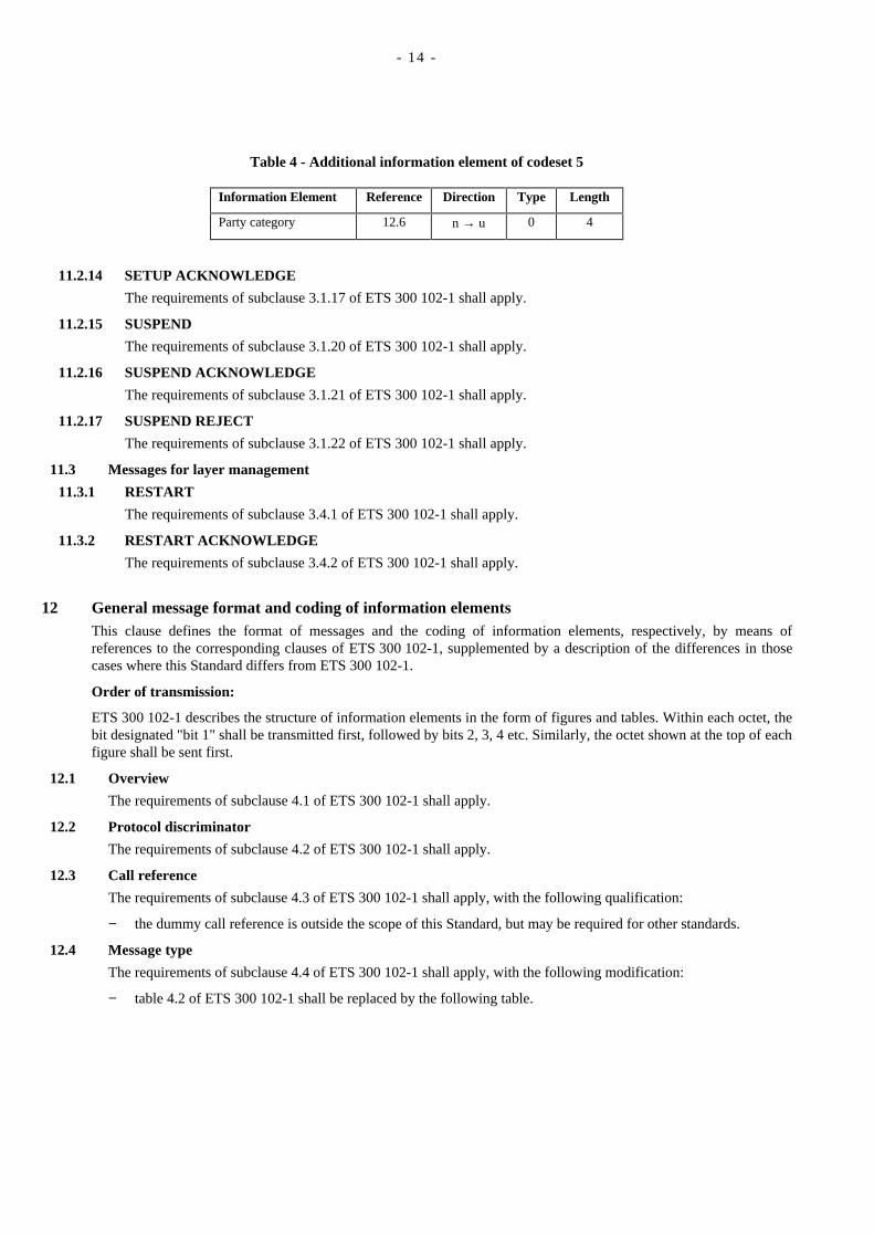
Table 4 - Additional information element of codeset 5
Information Element Reference Direction Type Length
Party category 12.6 n → u 0 4
11.2.14 SETUP ACKNOWLEDGE
The requirements of subclause 3.1.17 of ETS 300 102-1 shall apply.
11.2.15 SUSPEND
The requirements of subclause 3.1.20 of ETS 300 102-1 shall apply.
11.2.16 SUSPEND ACKNOWLEDGE
The requirements of subclause 3.1.21 of ETS 300 102-1 shall apply.
11.2.17 SUSPEND REJECT
The requirements of subclause 3.1.22 of ETS 300 102-1 shall apply.
11.3 Messages for layer management
11.3.1 RESTART
The requirements of subclause 3.4.1 of ETS 300 102-1 shall apply.
11.3.2 RESTART ACKNOWLEDGE
The requirements of subclause 3.4.2 of ETS 300 102-1 shall apply.
12 General message format and coding of information elementsThis clause defines the format of messages and the coding of information elements, respectively, by means ofreferences to the corresponding clauses of ETS 300 102-1, supplemented by a description of the differences in thosecases where this Standard differs from ETS 300 102-1.
Order of transmission:
ETS 300 102-1 describes the structure of information elements in the form of figures and tables. Within each octet, thebit designated "bit 1" shall be transmitted first, followed by bits 2, 3, 4 etc. Similarly, the octet shown at the top of eachfigure shall be sent first.
12.1 Overview
The requirements of subclause 4.1 of ETS 300 102-1 shall apply.
12.2 Protocol discriminator
The requirements of subclause 4.2 of ETS 300 102-1 shall apply.
12.3 Call reference
The requirements of subclause 4.3 of ETS 300 102-1 shall apply, with the following qualification:
− the dummy call reference is outside the scope of this Standard, but may be required for other standards.
12.4 Message type
The requirements of subclause 4.4 of ETS 300 102-1 shall apply, with the following modification:
− table 4.2 of ETS 300 102-1 shall be replaced by the following table.

- 15 -
Table 5 - Messages Types
8 7 6 5 4 3 2 1
0 0 0 Call establishment messages:
0000000
0001001
0011011
0111100
1011111
ALERTINGCALL PROCEEDINGCONNECTCONNECT ACKNOWLEDGEPROGRESSSETUPSETUP ACKNOWLEDGE
0 0 1 Call information phase messages:
000000
010010
110110
111000
000111
RESUMERESUME ACKNOWLEDGERESUME REJECTSUSPENDSUSPEND ACKNOWLEDGESUSPEND REJECT
0 1 0 Call clearing and Layer managementmessages:
00100
01101
11011
00111
11000
DISCONNECTRELEASERELEASE COMPLETERESTARTRESTART ACKNOWLEDGE
0 1 1 Miscellaneous messages:
0111
0110
0011
0100
0111
SEGMENTINFORMATIONSTATUSSTATUS ENQUIRY
All other settings are reserved.
12.5 Other information elements (Codeset 0)
12.5.1 Coding rules
The requirements of subclause 4.5.1 of ETS 300 102-1 shall apply, with the following modifications:
− the requirements of subclause 4.5.1.1 shall not apply: table 4.3 of ETS 300 102-1 shall be replaced by thefollowing table 6, which specifies the information elements of codeset 0 used in this Standard;
− the requirements of subclause 4.5.1.2 of ETS 300 102-1 (specifying the use of codeset 5) shall not apply; see12.6 of this Standard for a definition of codeset 5 elements.

- 16 -
Table 6 - Coding of the information element identifier coding (Codeset 0)
Coding Reference Max. Length(octets)
(Note 13)
8 7 6 5 4 3 2 1
1 : : : - - - - Single-octet informationelements:
000
001
010
--0
--0
--0
--1
ReservedShiftSending complete
12.5.312.5.23
11
0 : : : : : : : Variable-length informationelements:
000000000111111111
000000011001111111
000111100000011111
001001111111100111
010010100111100011
000000100000000000
000000001010101101
Segmented messageBearer capabilityCauseCall identityCall stateChannel identificationProgress indicatorDisplayDate/TimeConnected numberConnected subaddressCalling party numberCalling party subaddressCalled party numberCalled party subaddressRestart indicatorLow Layer compatibilityHigh Layer compatibility
12.5.2212.5.512.5.1212.5.612.5.712.5.1312.5.2012.5.1712.5.1612.5.1412.5.1512.5.1012.5.1112.5.812.5.912.5.2112.5.1912.5.18
41332103Note 1443482423242323233165
All other settings are reserved.
NOTE 13
The length limits for the variable-length information elements take into account only the present CCITTstandardized coding values. Future enhancements and expansions to this Standard will not be restricted to theselimits.
NOTE 14
The maximum length is network-dependent.
NOTE 15
The reserved values with bits 5 to 8 set to "0000" are for future information elements for which comprehensionby the receiver is required.
12.5.2 Extensions of codesets
The requirements of subclause 4.5.2 of ETS 300 102-1 shall apply, with the following modifications:
− codeset 5 is used for information elements defined by ETSI for PTN use;
− codeset 6: the terms 'national network' and 'national or international boundary' shall be replaced by 'localnetwork' and 'local network boundary' respectively in the text concerning codeset 6.
12.5.3 Locking shift procedure
The requirements of subclause 4.5.3 of ETS 300 102-1 shall apply, with the following modifications to table 4.4:
- 17 -
− codeset 5: information elements defined by ETSI for PTN use;
− replace 'national' by 'local' in the text concerning codeset 6.
12.5.4 Non-locking shift procedure
The requirements of subclause 4.5.4 of ETS 300 102-1 shall apply, with the following modifications to table 4.5:
− codeset 5: information elements defined by ETSI for PTN use;
− replace 'national' by 'local' in the text concerning codeset 6.
12.5.5 Bearer capability
The requirements of subclause 4.5.5 of ETS 300 102-1 shall apply, with the following exceptions:
− the information transfer capability 'restricted digital information' shall only apply in interworking cases;
− the requirements prohibiting the use of rate adaption according to CCITT Rec. V.120 ("ETSI Note" in userinformation layer 1 protocol) shall not apply;
− only the codings applicable to services defined in ETS 300 171 shall be used.
NOTE 16
ETR 018 gives guidance on the combinations of code values applicable to the different basic services.
12.5.6 Call identity
The requirements of subclause 4.5.6 of ETS 300 102-1 shall apply.
12.5.7 Call state
The requirements of subclause 4.5.7 of ETS 300 102-1 shall apply.
12.5.8 Called party number
The requirements of subclause 4.5.8 of ETS 300 102-1 shall apply, with the following modifications:
− type of number (octet 3): the coding specified in ETS 300 102-1 applies only to numbers from the CCITTRec. E.163/164 Numbering Plan;
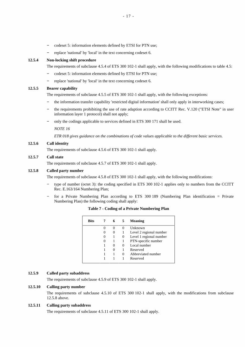
− for a Private Numbering Plan according to ETS 300 189 (Numbering Plan identification = PrivateNumbering Plan) the following coding shall apply:
Table 7 - Coding of a Private Numbering Plan
Bits 7 6 5 Meaning
00001111
00110011
01010101
UnknownLevel 2 regional numberLevel 1 regional numberPTN-specific numberLocal numberReservedAbbreviated numberReserved
12.5.9 Called party subaddress
The requirements of subclause 4.5.9 of ETS 300 102-1 shall apply.
12.5.10 Calling party number
The requirements of subclause 4.5.10 of ETS 300 102-1 shall apply, with the modifications from subclause12.5.8 above.
12.5.11 Calling party subaddress
The requirements of subclause 4.5.11 of ETS 300 102-1 shall apply.

- 18 -
12.5.12 Cause
The requirements of subclause 4.5.12 of ETS 300 102-1 shall apply, with the following qualifications:
− the Cause information element shall not appear more than once in a message;
− all values in the range 1 to 127 shall be accepted as valid cause values;
− any suitable cause value may be chosen from ETS 300 102-1, table 4.13, except where the procedures of thisStandard explicitly specify certain cause values, in which case those values shall be used;
− ETSI-specific cause values, encoded using coding standard '10', shall not apply.
NOTE 17
Refer to annex B for information on the use of cause values.
12.5.13 Channel identification
The requirements of subclause 4.5.13 of ETS 300 102-1 shall apply, with the following restrictions:
− channel type (octet 3.2): only the value 'B-channel units' shall be used (bits 4 to 1 set to 0011);
− Note 4 of ETS 300 102-1 figure 4.20 (optional repetition of octet 3.3) shall not apply.
NOTE 18
Refer to annex H of ETS 300 102-1 for examples of the encoding of the Channel identification informationelement.
12.5.14 Connected number
The purpose of the Connected number information element is to indicate which number is connected to a call.The connected number may be different from the called party number because of changes (e.g. call redirection,transfer) during the lifetime of the call.
The Connected number information element is coded as shown in figure 3. The coding of octets 3, 3a and 4 shallfollow the rules of subclause 4.5.10 of ETS 300 102-1, with the modifications from subclause 12.5.8 above.
8 7 6 5 4 3 2 1
Connected number information element identifier0 1 0 0 1 1 0 0 Octet 1
Length of connected number information Octet 2
0/1ext
Type of number Numbering plan identification Octet 3
1 Presentation 0 0 0 Screening Octet 3a*)ext Indicator spare Indicator
0spare Number digits
Octet 4(repeated)
* This octet is optional
Figure 3 - Connected number information element
12.5.15 Connected subaddress
The purpose of the Connected subaddress information element is to identify the subaddress of the connectedparty of a call. The Connected subaddress may be different from the called party subaddress because of changes(e.g. call redirections, transfer) during the lifetime of the call.
The Connected subaddress information element is coded as shown in figure 4. The coding of octets 3, 4, etc. shallfollow the rules of subclause 4.5.11 of ETS 300 102-1.
The maximum length of this information element is 23 octets.

- 19 -
8 7 6 5 4 3 2 1
Connected subaddress information element identifier0 1 0 0 1 1 0 1 Octet 1
Length of connected subaddress information Octet 2
1 odd/even 0 0 0 Octet 3ext Type of subaddress indicator spare
Subaddress informationOctet 4 etc.
Figure 4 - Connected subaddress information element
12.5.16 Date / time
The requirements of subclause 4.6.1 of ETS 300 102-1 shall apply.
12.5.17 Display
The requirements of subclause 4.5.15 of ETS 300 102-1 shall apply.
12.5.18 High layer compatibility (Layers 4 - 7)
The requirements of subclause 4.5.16 of ETS 300 102-1 shall apply.
NOTE 19
ETR 018 gives guidance on the combinations of code values applicable to the different basic services.
12.5.19 Low layer compatibility (Layers 1 - 3)
The requirements of subclause 4.5.18 of ETS 300 102-1 shall apply.
NOTE 20
ETR 018 gives guidance on the combinations of code values applicable to the different basic services.
12.5.20 Progress indicator
The requirements of subclause 4.5.22 of ETS 300 102-1 shall apply, with the following modifications:
− this information element may appear up to three times in a message, in ascending order according to progressdescription values.
− Progress description (octet 4):
1. Coding standard (octet 3) = 00 (CCITT-standardized coding): the requirements of sub-clause 4.5.22 ofETS 300 102-1 shall apply.
2. Coding standard (octet 3) = 01 (other international standards):
Bits 7 6 5 4 3 2 1 No Meaning0 0 1 0 0 0 0 16 Interworking with a public network0 0 1 0 1 0 0 20 Interworking with another private network
All other settings are reserved.
NOTE 21
Refer to annex A for information on the use of progress indicators.
12.5.21 Restart indicator
The requirements of subclause 4.5.24 of ETS 300 102-1 shall apply.
12.5.22 Segmented message
The requirements of subclause 4.5.25 of ETS 300 102-1 shall apply.

- 20 -
12.5.23 Sending complete
The requirements of subclause 4.5.26 of ETS 300 102-1 shall apply.
12.6 Information elements of codeset 5
Codeset 5 contains information elements defined by ETSI, in addition to those specified in CCITT Rec. Q.931.
In general, the coding rules defined for codeset 0 apply also to codeset 5.
Table 8 lists the information element identifiers for information elements of codeset 5 which are used for thisStandard.
Table 8 - Information element identifier coding (Codeset 5)
Coding Reference Length
8 7 6 5 4 3 2 1
1 :00
:00
:01
---
---
---
---
Single-octet information elements:reservedShift
-12.5.3
-1
0 :0
:1
:1
:0
:0
:1
:0
Variable-length information elements:Party category 12.6.1 3
All other settings are reserved.
12.6.1 Party category
The purpose of this information element is to indicate the category of a party involved in a call.
The Party category information element is coded as shown in figure 5.
8 7 6 5 4 3 2 1
Party category information element identifier
0 0 1 1 0 0 1 0 Octet 1
Length of party category information Octet 2
1 0 0 0 0 party category Octet 3ext reserved Meaning
0000
0011
0101
unknownextensionoperatoremergencyextension
All other settings are reserved.
Figure 5 - Party category information element

- 21 -
Annex A (informative)
Use of progress indicators
Progress description 1 indicates that interworking with a non-ISDN has occured within the network or networks which the callhas traversed.
Progress description 2 indicates that the destination TE is non-ISDN equipment.
Progress description 3 indicates that the origination TE is non-ISDN equipment.
Progress description 4 indicates that a call which had left the ISDN has returned at the same point it had left due to redirectionwithin the non-ISDN. This progress indicator would be employed if a progress indicator No. 1 "call is not end-to-end ISDN"had been delivered to the calling user before.
The use of progress description 8 is described in clause 8.
Progress description 16 indicates that the call comes from or goes to the public ISDN.
Progress description 20 indicates that the call comes from or goes to a private network other than the local PTN.

- 22 -
- 23 -
Annex B (informative)
Use of cause values
B.1 Definition of cause valuesFor a definition of cause values, refer to ETS 300 102-1 annex G.
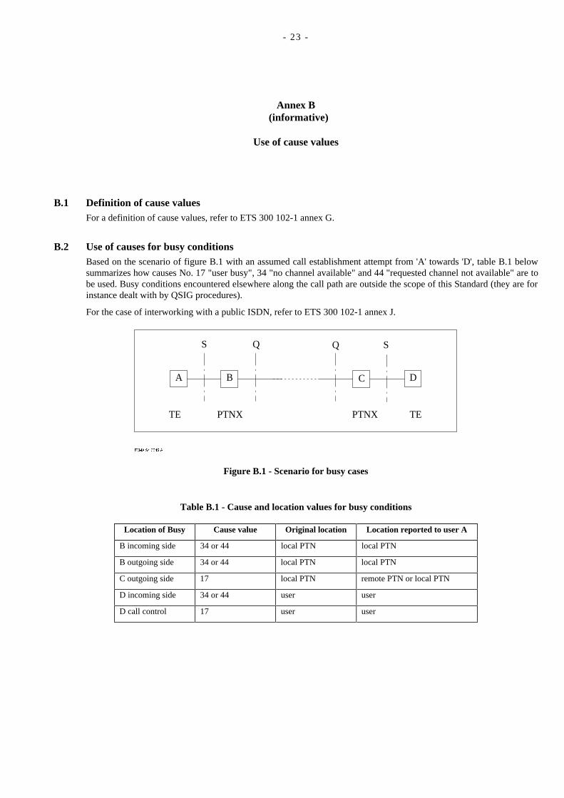
B.2 Use of causes for busy conditionsBased on the scenario of figure B.1 with an assumed call establishment attempt from 'A' towards 'D', table B.1 belowsummarizes how causes No. 17 "user busy", 34 "no channel available" and 44 "requested channel not available" are tobe used. Busy conditions encountered elsewhere along the call path are outside the scope of this Standard (they are forinstance dealt with by QSIG procedures).
For the case of interworking with a public ISDN, refer to ETS 300 102-1 annex J.
ECMA-94-0045-A
A D
S Q Q S
TE PTNX PTNX TE
B C
Figure B.1 - Scenario for busy cases
Table B.1 - Cause and location values for busy conditions
Location of Busy Cause value Original location Location reported to user A
B incoming side 34 or 44 local PTN local PTN
B outgoing side 34 or 44 local PTN local PTN
C outgoing side 17 local PTN remote PTN or local PTN
D incoming side 34 or 44 user user
D call control 17 user user

- 24 -
- 25 -
Annex C (informative)
Examples of message sequences
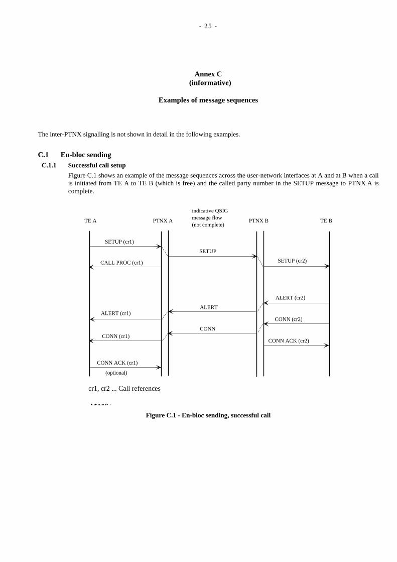
The inter-PTNX signalling is not shown in detail in the following examples.
C.1 En-bloc sendingC.1.1 Successful call setup
Figure C.1 shows an example of the message sequences across the user-network interfaces at A and at B when a callis initiated from TE A to TE B (which is free) and the called party number in the SETUP message to PTNX A iscomplete.
ECMA-94-0046-A
indicative QSIGmessage flow(not complete)
TE A PTNX A PTNX B TE B
SETUP
ALERT
CONN
SETUP (cr1)
CALL PROC (cr1)
ALERT (cr1)
CONN (cr1)
CONN ACK (cr1)
(optional)
SETUP (cr2)
ALERT (cr2)
CONN (cr2)
CONN ACK (cr2)
cr1, cr2 ... Call references
Figure C.1 - En-bloc sending, successful call
- 26 -
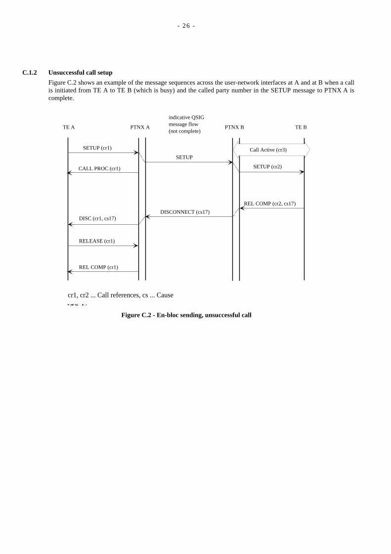
C.1.2 Unsuccessful call setup
Figure C.2 shows an example of the message sequences across the user-network interfaces at A and at B when a callis initiated from TE A to TE B (which is busy) and the called party number in the SETUP message to PTNX A iscomplete.
ECMA-94-0047-A
indicative QSIGmessage flow(not complete)
TE A PTNX A PTNX B TE B
SETUP
DISCONNECT (cs17)
SETUP (cr1)
CALL PROC (cr1)
DISC (cr1, cs17)
RELEASE (cr1)
REL COMP (cr1)
SETUP (cr2)
REL COMP (cr2, cs17)
cr1, cr2 ... Call references, cs ... Cause
Call Active (cr3)
Figure C.2 - En-bloc sending, unsuccessful call

- 27 -
C.2 Overlap sendingC.2.1 Successful call setup
Figure C.3 shows an example of the message sequences across the user-network interfaces at A and at B when a callis initiated from TE A to TE B (which is free) and the called party number in the SETUP message to PTNX A isnot complete.
ECMA-94-0048-A
indicative QSIGmessage flow(not complete)
TE A PTNX A PTNX B TE B
SETUP
ALERT
CONN
SETUP (cr1)
CALL PROC (cr1)
ALERT (cr1)
INFO (cr1)
CONN ACK (cr1)
(optional)
SETUP (cr2)
ALERT (cr2)
CONN (cr2)
CONN ACK (cr2)
cr1, cr2 ... Call references
SETUP ACK (cr1)
CONN (cr1)
INFO (cr1)
INFO (cr1)
INFO (cr1)INFO
INFO
Figure C.3 - Overlap sending, successful call

- 28 -
C.2.2 Unsuccessful call setup
Figure C.4 shows an example of the message sequences across the user-network interfaces at A and at B when a callis initiated from TE A to TE B (which is busy) and the called party number in the SETUP message to PTNX A isnot complete.
ECMA-94-0049-A
indicative QSIGmessage flow(not complete)
TE A PTNX A PTNX B TE B
SETUP
DISCONNECT (cs17)
SETUP (cr1)
CALL PROC (cr1)
DISC (cr1, cs17)
INFO (cr1)
REL COMP (cr1)
SETUP (cr2)
REL COMP (cr2, cs17)
cr1, cr2 ... Call references, cs ... Cause
SETUP ACK (cr1)
RELEASE (cr1)
INFO (cr1)
INFO (cr1)
INFO (cr1)INFO
INFO
Call Active (cr3)
Figure C.4 - Overlap sending, unsuccessful call

- 29 -
C.3 Call clearingFigure C.5 shows an example of normal call clearing from the active state, initiated by TE A.
ECMA-94-0051-A
TE A PTNX A PTNX B TE B
DISC (cr1, cs16)
RELEASE (cr1)
REL COMP (cr1)
cr1, cr2 ... Call references, cs ... Cause
DISC (cs16)
RELEASE
REL COMP
DISC (cr2, cs16)
RELEASE (cr2)
REL COMP (cr2)
Call Active between TE-A and TE-B
Figure C.5 - Normal call clearing

- 30 -

- 31 -
Annex D (informative)
Manufacturer-specific information
This Standard permits the inclusion in messages of non-standardized information which is specific to a particular manufacturer,a particular design of equipment, a particular network, etc.. This information is known as Manufacturer-Specific Information(MSI).
The exchange of MSI across a user-network interface may be achieved by means of information elements of codeset 6 or 7. Theerror procedures of subclause 7.3 will apply in the event of an information element being received and not recognized by aterminal or PTNX. Note that ambiguity may arise when two items of equipment use the same information element identifier fordifferent purposes.
A general purpose method of conveying MSI is by means of the Facility information element specified for supplementaryservices in another standard. This provides a transparent means of conveying information between a terminal and a PTNXwhich is not necessarily the terminal's local PTNX. It uses internationally-recognized Object Identifiers to avoid ambiguity.

- 32 -

- 33 -
Annex E (informative)
Bibliography
ETS 300 102-2 Integrated Services Digital Network (ISDN); User-network interface layer 3, Specifications forbasic call control, Specification Description Language (SDL) diagrams (1990).
ETS 300 055 Integrated Services Digital Network (ISDN); Terminal Portability (TP) supplementary service,Digital Subscriber Signalling System No. 1 (DSS1) protocol (1991).
ETR 018 Integrated Services Digital Network (ISDN); Application of the BC-, HLC-, LLC-informationelements by terminals supporting ISDN services.

- 34 -

- 35 -
Annex F (informative)
Terminal interchangeability
Terminals can be designed that will be compatible with both public ISDNs offering interfaces conforming to ETS 300 102-1and PTNs offering interfaces conforming to this Standard.

- 36 -
- 37 -
Annex G (normative)
Protocol Implementation Conformance Statement (PICS) Proforma
G.1 IntroductionThe supplier of a protocol implementation which is claimed to conform to this Standard shall complete one of thefollowing Protocol Implementation Conformance Statement (PICS) proformas. The PICS proforma in G.3 is for aPTNX. The PICS proforma in G.4 is for a TE.
A completed PICS proforma is the PICS for the implementation in question. The PICS is a statement of whichcapabilities and options of the protocol have been implemented. The PICS can have a number of uses, including use:
− by the protocol implementor, as a check list to reduce the risk of failure to conform to the Standard throughoversight;
− by the supplier and acquirer (or potential acquirer) of the implementation, as a detailed indication of thecapabilities of the implementation, stated relative to the common basis for understanding provided by the StandardPICS proforma;
− by the user (or potential user) of the implementation, as a basis for initially checking the possibility ofinterworking with another implementation (note that, while interworking cannot be guaranteed, failure to interworkcan often be predicted from incompatible PICS);
− by a protocol tester, as the basis for selecting appropriate tests against which to assess the claim for conformanceof the implementation.
G.2 Instructions for completing the PICS proformaG.2.1 General structure of the PICS proforma
The PICS proforma is a fixed-format questionnaire divided into subclauses each containing a group of individualitems. Each item is identified by an item number, the name of the item (question to be answered), and thereference(s) to the clause(s) specifying the item in the main body of this Standard.
The "Status" column indicates whether an item is applicable, and if so whether support is mandatory or optional.The following terms are used:
m mandatory (the capability is required for conformance to this Standard);
o optional (the capability is not required for conformance to this Standard, but if the capability isimplemented then it is required to conform to the protocol specifications);
o.<n> optional, but support of at least one of the group of options labelled by the same numeral <n> isrequired;
x prohibited;
c.<cond> conditional requirement, depending on support for the item or items listed in condition <cond>;
<item>:m simple-conditional requirement, the capability being mandatory if item number <item> issupported, otherwise not applicable;
<item>:o simple-conditional requirement, the capability being optional if item number <item> is supported,otherwise not applicable.
Answers to the questionnaire items are to be provided in the "Support" column, by simply marking an answer toindicate a restricted choice (Yes or No), or in the "Not Applicable" column (N/A).

- 38 -
G.2.2 Additional information
Items of additional information allow a supplier to provide further information intended to assist the interpretationof the PICS. It is not intented or expected that a large quantity will be supplied, and a PICS can be consideredcomplete without any such information. Examples might be an outline of the ways in which a (single)implementation can be set up to operate in a variety of environments and configurations.
References to items of additional information may be entered next to any answer in the questionnaire, and may beincluded in items of exception information.
G.2.3 Exception information
It may occasionally happen that a supplier will wish to answer an item with mandatory or prohibited status (after anyconditions have been applied) in a way that conflicts with the indicated requirements. No pre-printed answer will befound in the Support column for this. Instead, the supplier is required to write into the support column an x.<i>reference to an item of exception information, and to provide the appropriate rationale in the exception item itself.
An implementation for which an exception item is required in this way does not conform to this Standard. Apossible reason for the situation described above is that a defect in the Standard has been reported, a correction forwhich is expected to change the requirement not met by the implementation.

- 39 -
G.3 PICS proforma for ECMA-106 PTNX implementationG.3.1 Implementation identification
Supplier
Contact point for queries about thePICS
Implementation Name(s) and Version(s)
Other information necessary for fullidentification, e.g. name(s) andversion(s) for machines and/oroperating systems; system name(s)
Only the first three items are required for all implementations; other information may be completed as appropriate inmeeting the requirement for full identification.
The terms "Name" and "Version" should be interpreted appropriately to correspond with a supplier’s terminology(e.g. Type, Series, Model).
G.3.2 Protocol summary
Protocol version 3rd Edition
Addenda implemented
Amendments implemented
Have any exception items been required? No [ ] Yes [ ]
(The answer "Yes" means that the implementation does notconform to this Standard)
Date of Statement

- 40 -
G.3.3 Major capabilities
Item Questions/feature Reference Status N/A Support
Z1 Support of the 64 kbps unrestricted bearer 12.5.5 o.1 Yes [ ] No [ ]
Z2 Support of the 64 kbps bearer with speech transfercapability
12.5.5 o.1 Yes [ ] No [ ]
Z3 Support of the 64 kbps bearer with 3.1 khz audiotransfer capability
12.5.5 o.1 Yes [ ] No [ ]
Z4 Support of point-to-point configuration for basicaccess
o.2 Yes [ ] No [ ]
Z5 Support of multipoint configuration for basicaccess
o.2 Yes [ ] No [ ]
Z6 Support of primary rate access o.2 Yes [ ] No [ ]
G.3.4 General procedures
G.3.4.1 Use of the services of Layer 2
Item Questions/feature Reference Status N/A Support
A1 Establishment of a data link connection 7.1.1 m Yes [ ]
A2 Transfer of data 7.1.2 m Yes [ ]
G.3.4.2 Message segmentation procedures
Item Questions/feature Reference Status N/A Support
A3 Maximum message size generated 7.2 m Size [ ]
A4 Maximum message size received 7.2 m Size [ ]
A5 Length of data link information field generated< Maximum message size generated
7.2 o Yes [ ] No [ ]
A6 Length of data link information field received< Maximum message size received
7.2 o Yes [ ] No [ ]
A7 Procedures for message segmentation 7.2 c.1 m: Yes [ ]x: No [ ]
A8 Procedures for message reassembly 7.2 A6:m [ ] m: Yes [ ]
c.1 If A5, then mandatory else, prohibited

- 41 -
G.3.4.3 Handling of protocol error conditions
Item Questions/feature Reference Status N/A Support
A9 Treatment of protocol discriminator error 7.3 m Yes [ ]
A10 Treatment of too short message 7.3 m Yes [ ]
A11 Treatment of call reference errors 7.3 m Yes [ ]
A12 Treatment of message type or message sequenceerrors
7.3 m Yes [ ]
A13 Treatment of general information element errors 7.3 m Yes [ ]
A14 Treatment of mandatory information element errors 7.3 m Yes [ ]
A15 Treatment of non-mandatory information elementerrors
7.3 m Yes [ ]
A16 Treatment of data link reset 7.3 m Yes [ ]
A17 Treatment of data link failure 7.3 m Yes [ ]
G.3.4.4 Handling of a multipoint configuration
Item Questions/feature Reference Status N/A Support
A18 Limit of positive responses to a SETUP message ina multipoint configuration
7.4 Z5:o [ ] o: Yes [ ] No [ ]Limit [ ]
A19 Number of maintained state machines that track theoverall progression of an incoming call on abroadcast data link
7.4 Z5:m [ ] m: Yes [ ]Number [ ]
A20 Procedure for positive responses exceeding thelimit of PTN capabilities
7.4 A18:m [ ] m: Yes [ ]
G.3.4.5 Status and status enquiry
Item Questions/feature Reference Status N/A Support
A21 Receipt of a STATUS ENQUIRY message 7.5 m Yes [ ]
A22 Sending of a STATUS ENQUIRY message 7.5 o Yes [ ] No [ ]
A23 Receipt of a solicited STATUS message 7.5 A22:m [ ]m: Yes [ ]
A24 Receipt of an unsolicited STATUS message 7.5 m Yes [ ]

- 42 -
G.3.5 Messages and information elements for general procedures
Item Questions/feature Reference Status N/A Support
B1 Receipt of the messages in accordance with theprocedures supported and receipt of all thepermitted information elements in those messages
11 m Yes [ ]
B2 Sending of messages, including for each messagethose information elements marked as mandatoryfor that message, in accordance with proceduressupported
11 m Yes [ ]
B3 Sending of the Channel identification informationelement in a SETUP ACKNOWLEDGE, CALLPROCEEDING, ALERTING or CONNECTmessage when that message is a first response to aSETUP message
11 m Yes [ ]
B4 Sending of a Progress indicator informationelement in an ALERTING message in connectionwith the provision of in-band information/patterns
11.2.1 o Yes [ ] No [ ]
B5 Sending of a Party category information element inan ALERTING message
11.2.1 o Yes [ ] No [ ]
B6 Sending of a Progress indicator informationelement in a CALL PROCEEDING message inconnection with the provision of in-bandinformation/patterns
11.2.2 o Yes [ ] No [ ]
B7 Sending of a Progress indicator informationelement in a CONNECT message in connectionwith the provision of in-band information/patterns
11.2.3 o Yes [ ] No [ ]
B8 Sending of a Low layer compatibility informationelement in a CONNECT message
11.2.3 o Yes [ ] No [ ]
B9 Sending of a Party category information element ina CONNECT message
11.2.3 o Yes [ ] No [ ]
B10 Sending of Date/Time information element in aCONNECT message
11.2.3 o Yes [ ] No [ ]
B11 Sending of a Progress indicator informationelement in a DISCONNECT message in connectionwith the provision of in-band information/patterns
11.2.5 o Yes [ ] No [ ]
B12 Sending of a Cause information element in aPROGRESS message
11.2.7 o Yes [ ] No [ ]
B13 Sending of a Cause information element in aRELEASE message when it is not the first clearingmessage
11.2.8 o Yes [ ] No [ ]
B14 Sending of a Cause information element in aRELEASE COMPLETE message when it is not thefirst clearing message
11.2.9 o Yes [ ] No [ ]
B15 Sending of a Sending complete informationelement in a SETUP message when en bloc sending
11.2.13 o Yes [ ] No [ ]

- 43 -
B16 Sending of a Progress indicator informationelement in a SETUP message in connection withthe provision of in-band information/patterns
11.2.13 o Yes [ ] No [ ]
B17 Sending of a Calling party number informationelement in a SETUP message
11.2.13 o Yes [ ] No [ ]
B18 Sending of a Calling party subaddress informationelement in a SETUP message
11.2.13 o Yes [ ] No [ ]
B19 Sending of a Called party subaddress informationelement in a SETUP message
11.2.13 o Yes [ ] No [ ]
B20 Sending of a Low layer compatibility informationelement in a SETUP message
11.2.13 o Yes [ ] No [ ]
B21 Sending of a High layer compatibility informationelement in a SETUP message
11.2.13 o Yes [ ] No [ ]
B22 Sending of a Party category information element ina SETUP message
11.2.13 o Yes [ ] No [ ]
B23 Sending of a Progress indicator informationelement in a SETUP ACKNOWLEDGE messagein connection with the provision of in-bandinformation/patterns
11.2.14 o Yes [ ] No [ ]
B24 Sending of a Channel identification informationelement in a RESTART message
11.3.1 D1:o [ ] o: Yes [ ] No [ ]
B25 Message formats and codings for non-segmentedmessages and information elements supported
11 m Yes [ ]
B26 Message formats and codings for segmentedmessage types and information elements supported
11 (A7 or A8):m [ ] m: Yes [ ]

- 44 -
G.3.6 Procedures for circuit mode call control
G.3.6.1 Call establishment at the originating interface
Item Questions/feature Reference Status N/A Support
C1 Support of procedures for outgoing call at theoriginating interface
8.1 m Yes [ ]
G.3.6.2 Call establishment at the destination interface
Item Questions/feature Reference Status N/A Support
C2 Support of procedures for incoming call in apoint-to-point configuration
8.2 Z4:m [ ] Yes [ ]
C3 Support of procedures for incoming call in amultipoint terminal configuration
8.2 Z5:m [ ] Yes [ ]
C4 Support of procedures for incoming call on aprimary rate access
8.2 Z6:m [ ] Yes [ ]
G.3.6.3 Call clearing
Item Questions/feature Reference Status N/A Support
C5 Support of call clearing procedures whentones/announcement not provided
8.3 m Yes [ ]
C6 Support of call clearing procedures whentones/announcement provided
8.3 o Yes [ ] No [ ]
G.3.6.4 Call collisions
Item Questions/feature Reference Status N/A Support
C7 Support of the channel selection mechanism 8.5 m Yes [ ]
G.3.6.5 Suspend and resume procedure
Item Questions/feature Reference Status N/A Support
C8 Support of call suspend and resume procedure on abasic access
8.6 o Yes [ ] No [ ]

- 45 -
G.3.7 Procedures for layer management
Item Questions/feature Reference Status N/A Support
D1 Initiation of restart procedures 9.1 o Yes [ ] No [ ]
D2 Receipt of RESTART 9.1 m Yes [ ]
D3 Restart procedures - Restart collision 9.1 D1:m [ ]m: Yes [ ]
G.3.8 Timers
Item Questions/feature Reference Status N/A Support
E1 Implementation of T301 10 o Yes [ ] No [ ]Value [ ]
E2 Implementation of T302 10 m Yes [ ]Value [ ]
E3 Implementation of T303 10 m Yes [ ]Value [ ]
E4 Implementation of T304 10 m Yes [ ]Value [ ]
E5 Implementation of T305 10 m Yes [ ]Value [ ]
E6 Implementation of T306 10 C6:m [ ] m: Yes [ ]
E7 Implementation of T307 10 C8:m [ ] m: Yes [ ]
E8 Implementation of T308 10 m Yes [ ]
E9 Implementation of T309 10 m Yes [ ]
E10 Implementation of T310 10 m Yes [ ]
E11 Implementation of T312 10 m Yes [ ]
E12 Implementation of T314 10 A8:m [ ] m: Yes [ ]Value [ ]
E13 Implementation of T316 10 D1:m [ ] m: Yes [ ]
E14 Implementation of T317 10 m Yes [ ]Value [ ]
E15 Implementation of T322 10 A22:m [ ] m: Yes [ ]Value [ ]

- 46 -
G.4 PICS proforma for ECMA-106 TE implementationG.4.1 Implementation identification
Supplier
Contact point for queries about thePICS
Implementation Name(s) and Version(s)
Other information necessary for fullidentification, e.g. name(s) andversion(s) for machines and/oroperating systems; system name(s)
Only the first three items are required for all implementations; other information may be completed as appropriate inmeeting the requirement for full identification.
The terms "Name" and "Version" should be interpreted appropriately to correspond with a suppliers terminology(e.g. Type, Series, Model).
G.4.2 Protocol summary
Protocol version 3rd Edition
Addenda implemented
Amendments implemented
Have any exception items been required? No [ ] Yes [ ]
(The answer "Yes" means that the implementation does notconform to this Standard)
Date of Statement

- 47 -
G.4.3 Major capabilities
Item Questions/feature Reference Status N/A Support
Z1 Support of the 64 kbps unrestricted bearer 12.5.5 o.1 Yes [ ] No [ ]
Z2 Support of the 64 kbps bearer with speech transfercapability
12.5.5 o.1 Yes [ ] No [ ]
Z3 Support of the 64 kbps bearer with 3.1 khz audiotransfer capability
12.5.5 o.1 Yes [ ] No [ ]
Z4 Support of point-to-point configuration for basicaccess
o.2 Yes [ ] No [ ]
Z5 Support of multipoint configuration for basicaccess
o.2 Yes [ ] No [ ]
Z6 Support of primary rate access o.2 Yes [ ] No [ ]
Z7 Support of outgoing calls o.3 Yes [ ] No [ ]
Z8 Support of incoming calls o.3 Yes [ ] No [ ]
G.4.4 General procedures
G.4.4.1 Use of the services of Layer 2
Item Questions/feature Reference Status N/A Support
A1 Establishment of a data link connection 7.1.1 m Yes [ ]
A2 Transfer of data 7.1.2 m Yes [ ]
G.4.4.2 Message segmentation procedures
Item Questions/feature Reference Status N/A Support
A3 Maximum message size generated 7.2 m Size [ ]
A4 Maximum message size received 7.2 m Size [ ]
A5 Length of data link information field generated< Maximum generated message size
7.2 o Yes [ ] No [ ]
A6 Length of data link information field received< Maximum received message size
7.2 o Yes [ ] No [ ]
A7 Procedures for message segmentation 7.2 c.1 m: Yes [ ]x: No [ ]
A8 Procedures for message reassembly 7.2 A6:m [ ]m: Yes [ ]
c.1 If A5, then mandatory else, prohibited

- 48 -
G.4.4.3 Handling of protocol error conditions
Item Questions/feature Reference Status N/A Support
A9 Treatment of protocol discriminator error 7.3 m Yes [ ]
A10 Treatment of too short message 7.3 m Yes [ ]
A11 Treatment of call reference errors 7.3 m Yes [ ]
A12 Treatment of message type or sequence errors 7.3 m Yes [ ]
A13 Treatment of general information errors 7.3 m Yes [ ]
A14 Treatment of mandatory information element errors 7.3 m Yes [ ]
A15 Treatment of non-mandatory information elementerrors
7.3 m Yes [ ]
A16 Treatment of data link reset 7.3 m Yes [ ]
A17 Treatment of data link failure 7.3 m Yes [ ]
G.4.4.4 Status and status enquiry
Item Questions/feature Reference Status N/A Support
A18 Receipt of a STATUS ENQUIRY message 7.5 m Yes [ ]
A19 Sending of a STATUS ENQUIRY message 7.5 o Yes [ ]
A20 Receipt of a solicited STATUS message 7.5 A19:m [ ] m: Yes [ ]
A21 Receipt of an unsolicited STATUS message 7.5 m Yes [ ]

- 49 -
G.4.5 Messages and information elements for general procedures
G.4.5.1 Outgoing calls
This table shall apply only if the answer to item Z7 is "Yes".
Item Questions/feature Reference Status N/A Support
B1 Receipt of the messages in accordance with theprocedures supported and receipt of all thepermitted information elements in those messages
11 m Yes [ ]
B2 Sending of messages, including for each messagethose information elements marked as mandatoryfor that message, in accordance with proceduressupported
11 m Yes [ ]
B3 Sending of a Sending complete informationelement in an INFORMATION message whenoverlap sending is complete
11.2.6 C2:o [ ] o: Yes [ ] No [ ]
B4 Sending of a Cause information element in aRELEASE message when it is not the first clearingmessage
11.2.8 o Yes [ ] No [ ]
B5 Sending of a Cause information element in aRELEASE COMPLETE message when it is not thefirst clearing message
11.2.9 o Yes [ ] No [ ]
B6 Sending of a Call identity information element in aRESUME message
11.2.10 o Yes [ ] No [ ]
B7 Sending of a Channel identification informationelement in a SETUP message
11.2.13 o Yes [ ] No [ ]
B8 Sending of a Sending complete informationelement in a SETUP message when en bloc sending
11.2.13 C1:o [ ] o: Yes [ ] No [ ]
B9 Sending of a Progress indicator informationelement in a SETUP message
11.2.13 o Yes [ ] No [ ]
B10 Sending of a Calling party number informationelement in a SETUP message
11.2.13 o Yes [ ] No [ ]
B11 Sending of a Calling party subaddress informationelement in a SETUP message
11.2.13 o Yes [ ] No [ ]
B12 Sending of a Called party subaddress informationelement in a SETUP message
11.2.13 o Yes [ ] No [ ]
B13 Sending of a Low layer compatibility informationelement in a SETUP message
11.2.13 o Yes [ ] No [ ]
B14 Sending of a High layer compatibility informationelement in a SETUP message
11.2.13 o Yes [ ] No [ ]
B15 Sending of a Call identity information element in aSUSPEND message
11.2.15 o Yes [ ] No [ ]
B16 Sending of a Channel identification informationelement in a RESTART message
11.3.1 D1:o [ ] o: Yes [ ] No [ ]

- 50 -
B17 Message formats and codings for non-segmentedmessages and information elements supported
11 m Yes [ ]
B18 Message formats and codings for segmentedmessage types and information elements supported
11 (A7 or A8):m [ ] m: Yes [ ]
G.4.5.2 Incoming calls
This table shall apply only if the answer to item Z8 is "Yes".
Item Questions/feature Reference Status N/A Support
B19 Receipt of the messages in accordance with theprocedures supported and receipt of all thepermitted information elements in those messages
11 m Yes [ ]
B20 Sending of messages, including for each messagethose information elements marked as mandatoryfor that message, in accordance with proceduressupported
11 m Yes [ ]
B21 Sending of a Connected number informationmessage element in a CONNECT message
11.2.3 o Yes [ ] No [ ]
B22 Sending of a Connected subaddress informationelement in a CONNECT message
11.2.3 o Yes [ ] No [ ]
B23 Sending of a Low layer compatibility informationelement in a CONNECT message
11.2.3 o Yes [ ] No [ ]
B24 Sending of a Cause information element in aPROGRESS message
11.2.7 o Yes [ ] No [ ]
B25 Sending of a Cause information element in aRELEASE message when it is not the first clearingmessage
11.2.8 o Yes [ ] No [ ]
B26 Sending of a Cause information element in aRELEASE COMPLETE message when it is not thefirst clearing message
11.2.9 o Yes [ ] No [ ]
B27 Sending of a Call identity information element in aRESUME message
11.2.10 o Yes [ ] No [ ]
B28 Sending of a Call identity information element in asSUSPEND message
11.2.15 o Yes [ ] No [ ]
B29 Sending of a Channel identification informationelement in a RESTART message
11.3.1 D1:o [ ] o: Yes [ ] No [ ]
B30 Message formats and codings for non-segmentedmessages and information elements supported
11 m Yes [ ]
B31 Message formats and codings for segmentedmessage types and information elements supported
11 (A7 or A8):m [ ] m: Yes [ ]

- 51 -
G.4.6 Procedures for circuit mode call control
G.4.6.1 Call establishment for outgoing call
Item Questions/feature Reference Status N/A Support
C1 Support of en bloc sending procedures 8.1 Z7:o.4 [ ]o: Yes [ ] No [ ]
C2 Support of overlap sending procedures 8.1 Z7:o.4 [ ]o: Yes [ ] No [ ]
G.4.6.2 Call establishment for incoming call
Item Questions/feature Reference Status N/A Support
C3 Support of procedures for incoming call over apoint-to-point data link for basic access
8.2 (Z4 and Z8):m [ ] m: Yes [ ]
C4 Support of procedures for incoming call over aBroadcast data link for basic access
8.2 (Z5 and Z8):m [ ] m: Yes [ ]
C5 Support of procedures for incoming call on aprimary rate access
8.2 (Z6 and Z8):m [ ] m: Yes [ ]
G.4.6.3 Call clearing
Item Questions/feature Reference Status N/A Support
C6 Support of call clearing procedures whentones/announcement not provided
8.3 m Yes [ ]
C7 Support of call clearing procedures whentones/announcement provided
8.3 m Yes [ ]
G.4.6.4 Suspend and resume
Item Questions/feature Reference Status N/A Support
C8 Support of call suspend and resume procedure on abasic access
8.6 (Z4 or Z5):o [ ] o: Yes [ ] No [ ]
G.4.7 Procedures for layer management
Item Questions/feature Reference Status N/A Support
D1 Initiation of restart procedures 9.1 o Yes [ ] No [ ]
D2 Receipt of RESTART 9.1 m Yes [ ]
D3 Restart procedures - Restart collision 9.1 D1:m [ ]m: Yes [ ]

- 52 -
G.4.8 Timers
G.4.8.1 Outgoing calls
This table shall apply only if the answer to item Z7 is "Yes".
Item Questions/feature Reference Status N/A Support
E1 Implementation of T301 10 o Yes [ ] No [ ]Value [ ]
E2 Implementation of T304 10 C2:m [ ] m: Yes [ ]
E3 Implementation of T305 10 m Yes [ ]
E4 Implementation of T308 10 m Yes [ ]
E5 Implementation of T309 10 o Yes [ ] No [ ]Value [ ]
E6 Implementation of T310 10 o Yes [ ] No [ ]
E7 Implementation of T314 10 A8:m [ ] m: Yes [ ]
E8 Implementation of T316 10 D1:m [ ] m: Yes [ ]
E9 Implementation of T317 10 D1:m [ ] m: Yes [ ]Value [ ]
E10 Implementation of T322 10 A19:m [ ] m: Yes [ ]
G.4.8.2 Incoming calls
This table shall apply only if the answer to item Z8 is "Yes".
Item Questions/feature Reference Status N/A Support
E11 Implementation of T305 10 m Yes [ ]
E12 Implementation of T308 10 m Yes [ ]
E13 Implementation of T309 10 o Yes [ ] No [ ]
E14 Implementation of T313 10 m Yes [ ]
E15 Implementation of T314 10 A8:m [ ] m: Yes [ ]
E16 Implementation of T316 10 D1:m [ ] m: Yes [ ]
E17 Implementation of T317 10 m Yes [ ]Value [ ]
E18 Implementation of T322 10 A19:m [ ] m: Yes [ ]


This Third Edition of Standard ECMA-106 is available free of charge from:
ECMA114 Rue du RhôneCH-1204 GenevaSwitzerland
Fax: +41 22 849 60 01Internet: [email protected]
This Standard can also be downloaded as files E106-PSC.EXE and E106-DOC.EXE from ECMANEWS