pro upright bike pro recumbent bike - sportsmith · pro upright bike pro recumbent bike. 4 star...
TRANSCRIPT

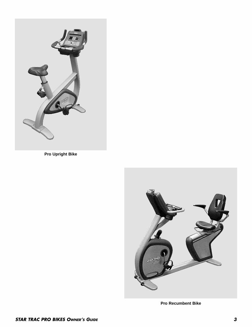
Pro Upright BikePro Recumbent Bike
O W N E R ’ S M A N U A L
Introduction . . . . . . . . . . . . . . . . . . . . . . . . . . . . . . . . . . . . . . . . . . . . . . . . . . . . . . . . . . . . . . . . . . . . . . . . . . . . . . . . . . 4About This Manual . . . . . . . . . . . . . . . . . . . . . . . . . . . . . . . . . . . . . . . . . . . . . . . . . . . . . . . . . . . . . . . . . . . . 4
Safety Instructions . . . . . . . . . . . . . . . . . . . . . . . . . . . . . . . . . . . . . . . . . . . . . . . . . . . . . . . . . . . . . . . . . . . . . . . . . . . . . 5English . . . . . . . . . . . . . . . . . . . . . . . . . . . . . . . . . . . . . . . . . . . . . . . . . . . . . . . . . . . . . . . . . . . . . . . . . . . . . . 5Dutch . . . . . . . . . . . . . . . . . . . . . . . . . . . . . . . . . . . . . . . . . . . . . . . . . . . . . . . . . . . . . . . . . . . . . . . . . . . . . . . 6French . . . . . . . . . . . . . . . . . . . . . . . . . . . . . . . . . . . . . . . . . . . . . . . . . . . . . . . . . . . . . . . . . . . . . . . . . . . . . . 6German . . . . . . . . . . . . . . . . . . . . . . . . . . . . . . . . . . . . . . . . . . . . . . . . . . . . . . . . . . . . . . . . . . . . . . . . . . . . . 7Italian . . . . . . . . . . . . . . . . . . . . . . . . . . . . . . . . . . . . . . . . . . . . . . . . . . . . . . . . . . . . . . . . . . . . . . . . . . . . . . 7Portuguese . . . . . . . . . . . . . . . . . . . . . . . . . . . . . . . . . . . . . . . . . . . . . . . . . . . . . . . . . . . . . . . . . . . . . . . . . . . 8Spanish . . . . . . . . . . . . . . . . . . . . . . . . . . . . . . . . . . . . . . . . . . . . . . . . . . . . . . . . . . . . . . . . . . . . . . . . . . . . . 8Swedish . . . . . . . . . . . . . . . . . . . . . . . . . . . . . . . . . . . . . . . . . . . . . . . . . . . . . . . . . . . . . . . . . . . . . . . . . . . . . 9Chinese . . . . . . . . . . . . . . . . . . . . . . . . . . . . . . . . . . . . . . . . . . . . . . . . . . . . . . . . . . . . . . . . . . . . . . . . . . . . . 9Japanese . . . . . . . . . . . . . . . . . . . . . . . . . . . . . . . . . . . . . . . . . . . . . . . . . . . . . . . . . . . . . . . . . . . . . . . . . . . . 10
Assembly and Setup . . . . . . . . . . . . . . . . . . . . . . . . . . . . . . . . . . . . . . . . . . . . . . . . . . . . . . . . . . . . . . . . . . . . . . . . . . . 11Pro Upright Bike Assembly and Setup . . . . . . . . . . . . . . . . . . . . . . . . . . . . . . . . . . . . . . . . . . . . . . . . . . . . . 11Pro Recumbent Bike Assembly and Setup . . . . . . . . . . . . . . . . . . . . . . . . . . . . . . . . . . . . . . . . . . . . . . . . . . 13
Operating Instructions . . . . . . . . . . . . . . . . . . . . . . . . . . . . . . . . . . . . . . . . . . . . . . . . . . . . . . . . . . . . . . . . . . . . . . . . . . 15Seat Adjustments . . . . . . . . . . . . . . . . . . . . . . . . . . . . . . . . . . . . . . . . . . . . . . . . . . . . . . . . . . . . . . . . . . . . . 15Pedal Strap Operation . . . . . . . . . . . . . . . . . . . . . . . . . . . . . . . . . . . . . . . . . . . . . . . . . . . . . . . . . . . . . . . . . 16Heart Rate Bar Operation (Pro Recumbent Bike) . . . . . . . . . . . . . . . . . . . . . . . . . . . . . . . . . . . . . . . . . . . . 16Display Panel Features . . . . . . . . . . . . . . . . . . . . . . . . . . . . . . . . . . . . . . . . . . . . . . . . . . . . . . . . . . . . . . . . . 16Hints and Tips for Getting Started . . . . . . . . . . . . . . . . . . . . . . . . . . . . . . . . . . . . . . . . . . . . . . . . . . . . . . . . 18Viewing Workout Data During a Program . . . . . . . . . . . . . . . . . . . . . . . . . . . . . . . . . . . . . . . . . . . . . . . . . . 18Cooldown Cycle . . . . . . . . . . . . . . . . . . . . . . . . . . . . . . . . . . . . . . . . . . . . . . . . . . . . . . . . . . . . . . . . . . . . . . . 19Using the Personal Fan . . . . . . . . . . . . . . . . . . . . . . . . . . . . . . . . . . . . . . . . . . . . . . . . . . . . . . . . . . . . . . . . . 19Heart Rate Monitoring . . . . . . . . . . . . . . . . . . . . . . . . . . . . . . . . . . . . . . . . . . . . . . . . . . . . . . . . . . . . . . . . . 19Quick Start . . . . . . . . . . . . . . . . . . . . . . . . . . . . . . . . . . . . . . . . . . . . . . . . . . . . . . . . . . . . . . . . . . . . . . . . . . 20Preset Programs . . . . . . . . . . . . . . . . . . . . . . . . . . . . . . . . . . . . . . . . . . . . . . . . . . . . . . . . . . . . . . . . . . . . . . 20Training Tools Programs . . . . . . . . . . . . . . . . . . . . . . . . . . . . . . . . . . . . . . . . . . . . . . . . . . . . . . . . . . . . . . . . 23
Preventative Maintenance . . . . . . . . . . . . . . . . . . . . . . . . . . . . . . . . . . . . . . . . . . . . . . . . . . . . . . . . . . . . . . . . . . . . . . . 28Daily Maintenance . . . . . . . . . . . . . . . . . . . . . . . . . . . . . . . . . . . . . . . . . . . . . . . . . . . . . . . . . . . . . . . . . . . . 28Weekly Maintenance . . . . . . . . . . . . . . . . . . . . . . . . . . . . . . . . . . . . . . . . . . . . . . . . . . . . . . . . . . . . . . . . . . . 28Monthly Maintenance . . . . . . . . . . . . . . . . . . . . . . . . . . . . . . . . . . . . . . . . . . . . . . . . . . . . . . . . . . . . . . . . . . 28
Manager / Maintenance Mode . . . . . . . . . . . . . . . . . . . . . . . . . . . . . . . . . . . . . . . . . . . . . . . . . . . . . . . . . . . . . . . . . . . . 28Manager Mode . . . . . . . . . . . . . . . . . . . . . . . . . . . . . . . . . . . . . . . . . . . . . . . . . . . . . . . . . . . . . . . . . . . . . . . . 28Maintenance Mode . . . . . . . . . . . . . . . . . . . . . . . . . . . . . . . . . . . . . . . . . . . . . . . . . . . . . . . . . . . . . . . . . . . . 28
Troubleshooting . . . . . . . . . . . . . . . . . . . . . . . . . . . . . . . . . . . . . . . . . . . . . . . . . . . . . . . . . . . . . . . . . . . . . . . . . . . . . . . 31Start-Up Service Messages . . . . . . . . . . . . . . . . . . . . . . . . . . . . . . . . . . . . . . . . . . . . . . . . . . . . . . . . . . . . . . 31
Regulatory Information . . . . . . . . . . . . . . . . . . . . . . . . . . . . . . . . . . . . . . . . . . . . . . . . . . . . . . . . . . . . . . . . . . . . . . . . . 31
2 STAR TRAC PRO BIKES OWNER’S GUIDE
TABLE OF CONTENTS
Copyright 2003. Star Trac by Unisen, Inc. All rights reserved, including those to reproduce this book or parts thereof in any form without first obtaining written permissionfrom Star Trac.
Every effort has been made to keep this information current; however, periodically, changes are made to the information herein, and these changes will be incorporated intonew editions of this publication. All product names and logos are trademarks of their respective owners. Printed in the USA.
STAR TRAC PRO BIKES OWNER’S GUIDE 3
Pro Upright Bike
Pro Recumbent Bike
4 STAR TRAC PRO BIKES OWNER’S GUIDE
Thank you for choosing the STAR TRAC PRO BIKE. The Upright and Recumbent Bikes have been designed to provide the userthe most rewarding experience based upon the carefully planned features it possesses. The design elements of these Bikes willprovide you with a comfortable, intuitive, safe and reliable experience, guiding you to a habit-forming lifestyle. Our mission is toprovide products to mold lifelong habits for health and fitness, and our Bikes will provide the path to meet your goals. Enjoy theride.
ABOUT THIS MANUALThis manual is applicable to the STAR TRAC PRO UPRIGHT BIKE and the STAR TRAC PRO RECUMBENT BIKE. Themanual is divided into eight sections, as follows:
Introduction
Provides an overview of each section within the manual.
Safety Instructions
Provides guidelines, in multiple languages, for safely operating the Star Trac Pro Bikes.
Assembly and Setup
Provides instructions for unpacking, assembling and setting up the Star Trac Pro Bikes.
Operating Instructions
Provides a detailed description of the Display Panel, and includes step-by-step instructions for operating the Star TracPro Bikes.
Preventative Maintenance
Describes the preventative maintenance measures required to keep the Star Trac Pro Bikes in top condition.
Manager / Maintenance Mode
Provides step-by-step instructions for changing universal parameters on Star Trac Pro Bikes, and for performing built-intesting procedures.
Troubleshooting
Describes the start-up and shutdown messages provided as a result of the self-test routine.
Regulatory Information
Provides regulatory information for the Star Trac Pro Bikes.
INTRODUCTION

STAR TRAC PRO BIKES OWNER’S GUIDE 5
This chapter includes fitness safeguards and precautions for the installation and use of the Star Trac Pro Bikes. Please read thischapter carefully before installing or using your equipment.
Safety instructions are provided in the following languages (in the order shown):
■ English
■ Dutch
■ French
■ German
■ Italian
■ Portuguese
■ Spanish
■ Swedish
■ Chinese
■ Japanese
PRECAUTIONSThese safety notes are directed to you as the owner of the Star Trac Pro Bike. Please train all your users and fitness staff to fol-low these safety instructions.
SAFETY INSTRUCTIONS
Do
■ Do encourage each of your users to discuss theirhealth program or fitness regimen with a healthcareprofessional.
■ Do stop operating your Pro Bike if you feel dizzy orfaint.
■ Do perform regular preventative maintenance.
■ Do exercise slowly until you reach a level of comfort.
■ Do use the Pro Bike only for its intended use, asdescribed in this manual.
Do Not
■ Do not let unsupervised children operate your ProBike.
■ Do not use without athletic shoes.
■ Do not use in rainy weather outdoors, or in anenclosed pool environment.
■ Do not drop or insert any object, hands, or feet intoany opening, or underneath your Pro Bike.
■ Do not attempt to remove any shrouds or modify yourPro Bike.
WARNINGYour Star Trac Pro Bike is designed for aerobic exercise in a commercial or consumer environment.
Please check with your physician prior to beginning any exercise program.
Do not push yourself to excess. Stop if you are feeling faint, dizzy, or exhausted. Use common sense whencycling.
Read the Owner's Manual in its entirety before operating your cycle.
Failure to obey this warning can result in injury or death.

VEILIGHEIDSINSTRUCTIESDeze veiligheidsinstructies zijn aan u gericht als de eigenaar van de Star Trac Pro Bikes. Train uw leden en fitness-personeel omdezelfde veiligheidsinstructies te volgen.
CONSIGNES DE SÉCURITÉCes consignes de sécurité sont destinées au propriétaire du Vélo d,exercice Star Trac. Veuillez enseigner ces consignes à tous vosmembres et employés.
Doe Dit Wel
■ Moedig uw leden aan om hun gezondheids- of fit-nessprogramma met een geneeskundige te bespreken.
■ Stop met de fiets als u zich duizelig voelt of het gevoelheeft dat u flauwvalt.
■ Verricht regelmatig preventief onderhoud.
■ Begin langzaam totdat u een comfortabel en veiligniveau heeft bereikt.
■ Gebruik het apparaat alleen voor het doel waarvoorhet bestemd is en zoals in dit handboek beschreven.
Doe Dit Neit
■ Laat kinderen niet zonder toezicht de fiets bedienen.
■ Plaats uw voeten niet onder uw fiets.
■ Gebruik de fiets niet zonder sportschoenen.
■ Niet buiten in regenachtig weer gebruiken of in eenomgeving met een overdekt zwembad.
■ Laat nooit objecten in het apparaat vallen en steekgeen objecten, handen of voeten in welke opening danook of onder het apparaat.
■ Verwider nooit afschermingen en verander het appa-raat niet.
WAARSCHUWINGUw Star Trac Pro Bike is ontworpen voor aerobics in een commerciële of consumentenomgeving.
Vraag advies aan uw arts voordat u met een fitnessprogramma begint.
Vraag niet teveel van uzelf. Stop als u het gevoel heeft dat u flauw gaat vallen, als u duizelig bent of uit-geput. Gebruik uw gezonde verstand bij het steppen. Lees de gebruikshandleiding helemaal door voordat uuw fiets gebruikt.
À Faire
■ Encouragez vos membres à disuter de leur pro-gramme de santé ou d'exercice avec un médecin.
■ Arrêtez tout exercice sur le vélo si vous éprouvez unétourdissement ou une défaillance.
■ Effectuez régulièrement un entretien préventif.
■ Exercez-vous lentement jusqu'à ce que vous vous sen-tiez à l'aise et en sécurité.
■ N'utilisez cet appareil que dans le but pour lequel ilest conçu.
À Ne Pas Faire
■ Ne laissez pas des enfants utiliser le vélo sans sur-veillance.
■ Ne placez pas vos pieds sous le vélo.
■ Ne permettez à personne de s'exercer sans chaussuresathlétiques.
■ N'utilisez pas l'appareil à l'extérieur par temps plu-vieux ou à proximité d'une piscine.
■ N'insérez jamais la main, le pied ou un objet dand lesouvertures de l'appareil, ni sous l'appareil.
■ Ne mofifiez jamais cet appareil et ne retirez aucun deses éléments protecteurs.
MISE EN GARDEVotre Vélo Star Trac est conçu pour l'exercice d'aérobic dans un contexte commercial ou à la maison.
Veuillez consulter votre médecin avant d'entreprendre tout programme d'exercice.
Évitez tout exercice excessif. Arrêtez us viys éprouvez un étourdissement, une défaillance ou de la fatigue.Fiez-vous à votre bon sens. Lisez attentivement la notice d'utilisation dans son intégralité avant d'utiliservotre vélo.
6 STAR TRAC PRO BIKES OWNER’S GUIDE
STAR TRAC PRO BIKES OWNER’S GUIDE 7
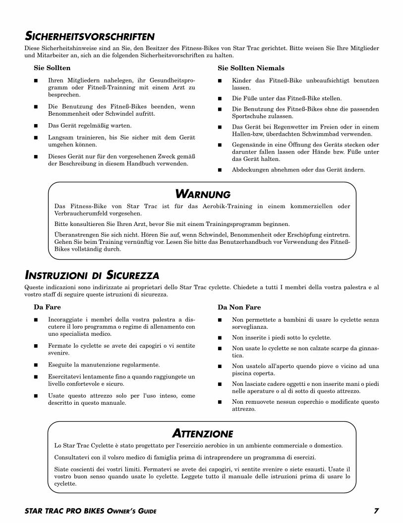
SICHERHEITSVORSCHRIFTENDiese Sicherheitshinweise sind an Sie, den Besitzer des Fitness-Bikes von Star Trac gerichtet. Bitte weisen Sie Ihre Mitgliederund Mitarbeiter an, sich an die folgenden Sicherheitsvorschriften zu halten.
INSTRUZIONI DI SICUREZZAQueste indicazioni sono indirizzate ai proprietari dello Star Trac cyclette. Chiedete a tutti I membri della vostra palestra e alvostro staff di seguire queste istruzioni di sicurezza.
Sie Sollten
■ Ihren Mitgliedern nahelegen, ihr Gesundheitspro-gramm oder Fitneß-Trainning mit einem Arzt zubesprechen.
■ Die Benutzung des Fitneß-Bikes beenden, wennBenommenheit oder Schwindel aufritt.
■ Das Gerät regelmäßig warten.
■ Langsam trainieren, bis Sie sicher mit dem Gerätumgehen können.
■ Dieses Gerät nur für den vorgesehenen Zweck gemäßder Beschreibung in diesem Handbuch verwenden.
Sie Sollten Niemals
■ Kinder das Fitneß-Bike unbeaufsichtigt benutzenlassen.
■ Die Füße unter das Fitneß-Bike stellen.
■ Die Benutzung des Fitneß-Bikes ohne die passendenSportschuhe zulassen.
■ Das Gerät bei Regenwetter im Freien oder in einemHallen-bzw, überdachten Schwimmbad verwenden.
■ Gegensände in eine Öffnung des Geräts stecken oderdarunter fallen lassen oder Hände bzw. Füße unterdas Gerät halten.
■ Abdeckungen abnehmen oder das Gerät ändern.
WARNUNGDas Fitness-Bike von Star Trac ist für das Aerobik-Training in einem kommerziellen oderVerbraucherumfeld vorgesehen.
Bitte konsultieren Sie Ihren Arzt, bevor Sie mit einem Trainingsprogramm beginnen.
Überanstrengen Sie sich nicht. Hören Sie auf, wenn Schwindel, Benommenheit oder Erschöpfung eintretrn.Gehen Sie beim Training vernünftig vor. Lesen Sie bitte das Benutzerhandbuch vor Verwendung des Fitneß-Bikes vollständig durch.
Da Fare
■ Incoraggiate i membri della vostra palestra a dis-cutere il loro programma o regime di allenamento conuno specialista medico.
■ Fermate lo cyclette se avete dei capogiri o vi sentitesvenire.
■ Eseguite la manutenzione regolarmente.
■ Esercitatevi lentamente fino a quando raggiungete unlivello confortevole e sicuro.
■ Usate questo attrezzo solo per l'uso inteso, comedescritto in questo manuale.
Da Non Fare
■ Non permettete a bambini di usare lo cyclette senzasorveglianza.
■ Non inserite i piedi sotto lo cyclette.
■ Non usate lo cyclette se non calzate scarpe da ginnas-tica.
■ Non usatelo all'aperto quendo piove o vicino ad unapiscina coperta.
■ Non lasciate cadere oggetti e non inserite mani o piedinelle aperature o al di sotto di questo attrezzo.
■ Non remuovete nessun coperchio o modificate questoattrezzo.
ATTENZIONELo Star Trac Cyclette è stato progettato per l'esercizio aerobico in un ambiente commerciale o domestico.
Consultatevi con il volsro medico di famiglia prima di intraprendere un programma di esercizi.
Siate coscienti dei vostri limiti. Fermatevi se avete dei capogiri, vi sentite svenire o siete esausti. Usate ilvostro buon senso quando usate lo cyclette. Leggete tutto il manuale delle istruzioni prima di usare locyclette.
8 STAR TRAC PRO BIKES OWNER’S GUIDE
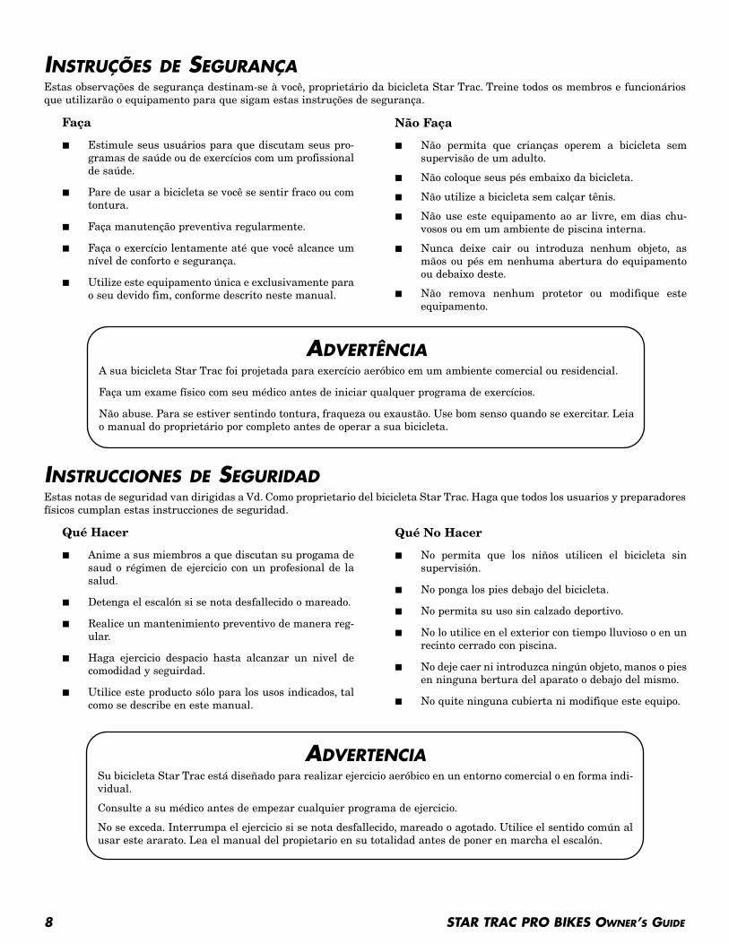
INSTRUÇÕES DE SEGURANÇAEstas observações de segurança destinam-se à você, proprietário da bicicleta Star Trac. Treine todos os membros e funcionáriosque utilizarão o equipamento para que sigam estas instruções de segurança.
INSTRUCCIONES DE SEGURIDADEstas notas de seguridad van dirigidas a Vd. Como proprietario del bicicleta Star Trac. Haga que todos los usuarios y preparadoresfísicos cumplan estas instrucciones de seguridad.
Faça
■ Estimule seus usuários para que discutam seus pro-gramas de saúde ou de exercícios com um profissionalde saúde.
■ Pare de usar a bicicleta se você se sentir fraco ou comtontura.
■ Faça manutenção preventiva regularmente.
■ Faça o exercício lentamente até que você alcance umnível de conforto e segurança.
■ Utilize este equipamento única e exclusivamente parao seu devido fim, conforme descrito neste manual.
Não Faça
■ Não permita que crianças operem a bicicleta semsupervisão de um adulto.
■ Não coloque seus pés embaixo da bicicleta.
■ Não utilize a bicicleta sem calçar tênis.
■ Não use este equipamento ao ar livre, em dias chu-vosos ou em um ambiente de piscina interna.
■ Nunca deixe cair ou introduza nenhum objeto, asmãos ou pés em nenhuma abertura do equipamentoou debaixo deste.
■ Não remova nenhum protetor ou modifique esteequipamento.
ADVERTÊNCIAA sua bicicleta Star Trac foi projetada para exercício aeróbico em um ambiente comercial ou residencial.
Faça um exame físico com seu médico antes de iniciar qualquer programa de exercícios.
Não abuse. Para se estiver sentindo tontura, fraqueza ou exaustão. Use bom senso quando se exercitar. Leiao manual do proprietário por completo antes de operar a sua bicicleta.
Qué Hacer
■ Anime a sus miembros a que discutan su progama desaud o régimen de ejercicio con un profesional de lasalud.
■ Detenga el escalón si se nota desfallecido o mareado.
■ Realice un mantenimiento preventivo de manera reg-ular.
■ Haga ejercicio despacio hasta alcanzar un nivel decomodidad y seguirdad.
■ Utilice este producto sólo para los usos indicados, talcomo se describe en este manual.
Qué No Hacer
■ No permita que los niños utilicen el bicicleta sinsupervisión.
■ No ponga los pies debajo del bicicleta.
■ No permita su uso sin calzado deportivo.
■ No lo utilice en el exterior con tiempo lluvioso o en unrecinto cerrado con piscina.
■ No deje caer ni introduzca ningún objeto, manos o piesen ninguna bertura del aparato o debajo del mismo.
■ No quite ninguna cubierta ni modifique este equipo.
ADVERTENCIASu bicicleta Star Trac está diseñado para realizar ejercicio aeróbico en un entorno comercial o en forma indi-vidual.
Consulte a su médico antes de empezar cualquier programa de ejercicio.
No se exceda. Interrumpa el ejercicio si se nota desfallecido, mareado o agotado. Utilice el sentido común alusar este ararato. Lea el manual del propietario en su totalidad antes de poner en marcha el escalón.
STAR TRAC PRO BIKES OWNER’S GUIDE 9
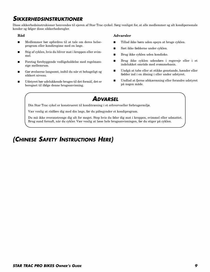
SIKKERHEDSINSTRUKTIONERDisse sikkerhedsinstrukioner henvendes til ejeren af Star Trac cyckel. Sørg venligst for, at alle medlemmer og alt kondipersonalekender og følger disse sikkerhedsregler.
(CHINESE SAFETY INSTRUCTIONS HERE)
Råd
■ Medlemmer bør opfordres til at tale om deres helse-program eller kondiregime med en læge.
■ Stig af cyklen, hvis du bliver mat i kroppen eller svim-mel.
■ Foretag forebyggende vedligeholdelse med regelmæs-sige mellemrum.
■ Gør øvelserne langsomt, indtil du når et behageligt ogsikkert niveau.
■ Udstyret bør udelukkende bruges til det formål, det erberegnet til ifølge denne brugsanvisning.
Advarsler
■ Tillad ikke børn uden opsyn at bruge cyklen.
■ Sæt ikke fødderne under cyklen.
■ Brug ikke cyklen uden kondisko.
■ Brug ikke cyklen udendørs i regnvejr eller i etindelukket område med svømmebasin.
■ Undgå at tabe eller at stikke genstande, hænder ellerfødder ind i en åbning i eller under udstyret.
■ Undlad at fjerne afskærmning eller forandre udstyretpå nogen måde.
ADVARSELDin Star Trac cykel er konstrueret til konditræning i et erhvervseller forbrugermiljø.
Vær venlig at rådføre dig med din læge, før du påbegynder et kondiprogram.
Du må ikke overanstrenge dig alt for meget. Stop hvis du føler dig mat i kroppen, svimmel eller udmattet.Brug sund fornuft, når du cykler. Vær venlig at læse hele brugsanvisningen, før du stiger på cyklen.

10 STAR TRAC PRO BIKES OWNER’S GUIDE
(JAPANESE SAFETY INSTRUCTIONS HERE)
STAR TRAC PRO BIKES OWNER’S GUIDE 11
ASSEMBLY AND SETUP
PRO UPRIGHT BIKE ASSEMBLY AND SETUPUse the following procedures to unpack and assemble your STAR TRAC PRO UPRIGHT BIKE.
UNPACKINGOpen the shipping carton, remove all parts from the carton and foam inserts, and verify that the following parts are included inyour shipment:
Take time now to enter your Pro Bike serial number in the space below. If parts are missing, or if you have any operational ques-tions, please call Star Trac’s Service Department at (800) 503-1221; have your serial number ready.
Serial No. ___________________________
ASSEMBLY
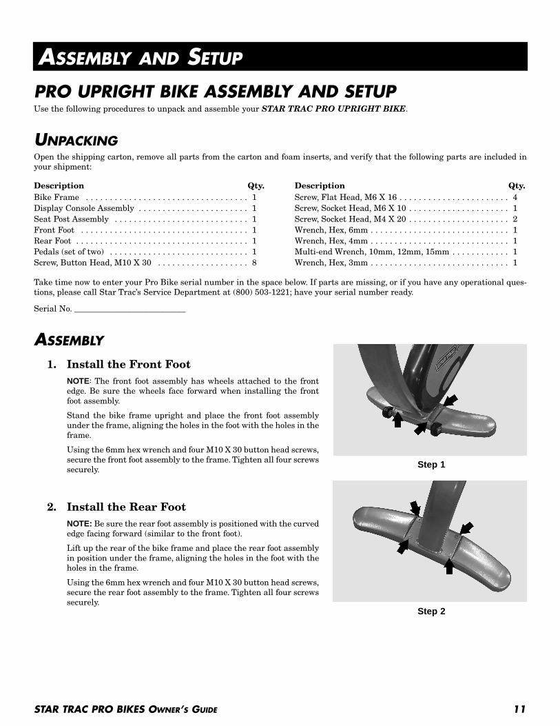
1. Install the Front FootNOTE: The front foot assembly has wheels attached to the frontedge. Be sure the wheels face forward when installing the frontfoot assembly.
Stand the bike frame upright and place the front foot assemblyunder the frame, aligning the holes in the foot with the holes in theframe.
Using the 6mm hex wrench and four M10 X 30 button head screws,secure the front foot assembly to the frame. Tighten all four screwssecurely.
2. Install the Rear FootNOTE: Be sure the rear foot assembly is positioned with the curvededge facing forward (similar to the front foot).
Lift up the rear of the bike frame and place the rear foot assemblyin position under the frame, aligning the holes in the foot with theholes in the frame.
Using the 6mm hex wrench and four M10 X 30 button head screws,secure the rear foot assembly to the frame. Tighten all four screwssecurely.
Description Qty.Bike Frame . . . . . . . . . . . . . . . . . . . . . . . . . . . . . . . . . . 1Display Console Assembly . . . . . . . . . . . . . . . . . . . . . . . 1Seat Post Assembly . . . . . . . . . . . . . . . . . . . . . . . . . . . . 1Front Foot . . . . . . . . . . . . . . . . . . . . . . . . . . . . . . . . . . . 1Rear Foot . . . . . . . . . . . . . . . . . . . . . . . . . . . . . . . . . . . . 1Pedals (set of two) . . . . . . . . . . . . . . . . . . . . . . . . . . . . . 1Screw, Button Head, M10 X 30 . . . . . . . . . . . . . . . . . . . 8
Description Qty.Screw, Flat Head, M6 X 16 . . . . . . . . . . . . . . . . . . . . . . . 4Screw, Socket Head, M6 X 10 . . . . . . . . . . . . . . . . . . . . . 1Screw, Socket Head, M4 X 20 . . . . . . . . . . . . . . . . . . . . . 2Wrench, Hex, 6mm . . . . . . . . . . . . . . . . . . . . . . . . . . . . . 1Wrench, Hex, 4mm . . . . . . . . . . . . . . . . . . . . . . . . . . . . . 1Multi-end Wrench, 10mm, 12mm, 15mm . . . . . . . . . . . . 1Wrench, Hex, 3mm . . . . . . . . . . . . . . . . . . . . . . . . . . . . . 1
Step 1
Step 2
12 STAR TRAC PRO BIKES OWNER’S GUIDE
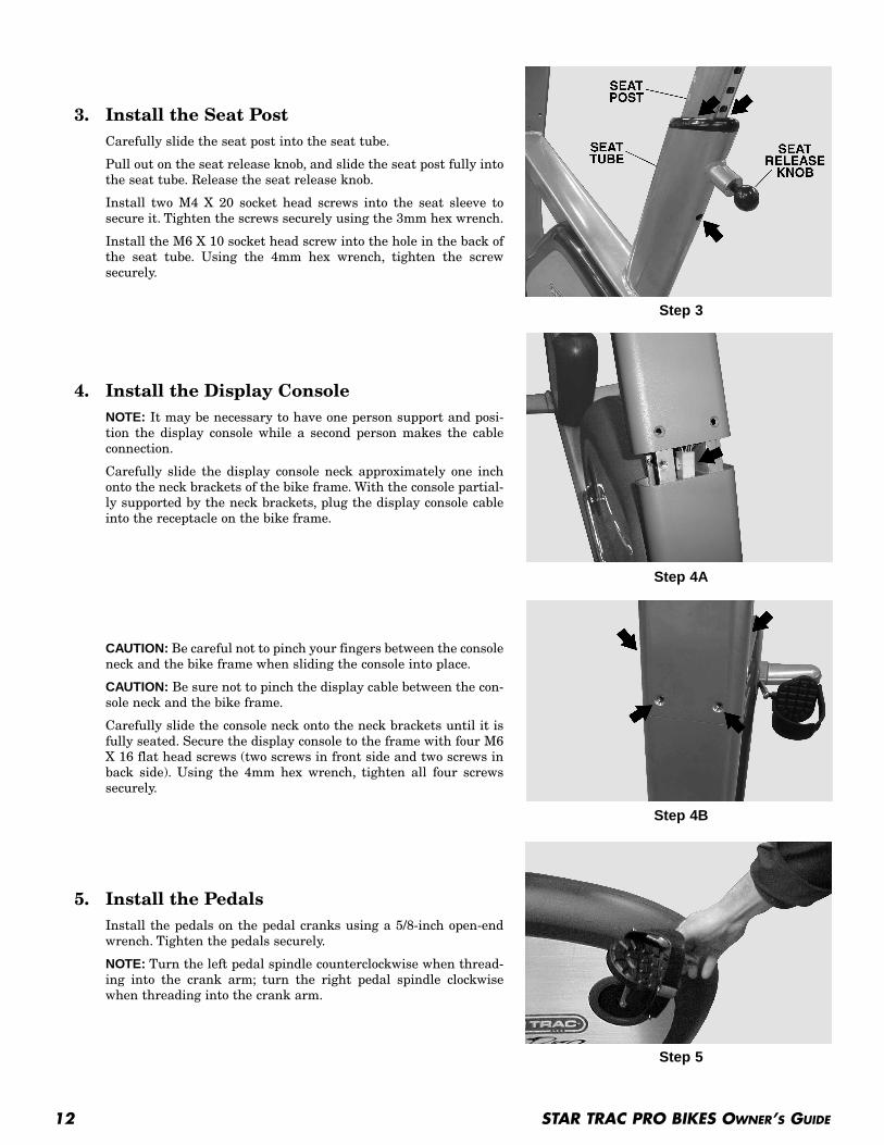
3. Install the Seat PostCarefully slide the seat post into the seat tube.
Pull out on the seat release knob, and slide the seat post fully intothe seat tube. Release the seat release knob.
Install two M4 X 20 socket head screws into the seat sleeve tosecure it. Tighten the screws securely using the 3mm hex wrench.
Install the M6 X 10 socket head screw into the hole in the back ofthe seat tube. Using the 4mm hex wrench, tighten the screwsecurely.
4. Install the Display ConsoleNOTE: It may be necessary to have one person support and posi-tion the display console while a second person makes the cableconnection.
Carefully slide the display console neck approximately one inchonto the neck brackets of the bike frame. With the console partial-ly supported by the neck brackets, plug the display console cableinto the receptacle on the bike frame.
CAUTION: Be careful not to pinch your fingers between the consoleneck and the bike frame when sliding the console into place.
CAUTION: Be sure not to pinch the display cable between the con-sole neck and the bike frame.
Carefully slide the console neck onto the neck brackets until it isfully seated. Secure the display console to the frame with four M6X 16 flat head screws (two screws in front side and two screws inback side). Using the 4mm hex wrench, tighten all four screwssecurely.
5. Install the PedalsInstall the pedals on the pedal cranks using a 5/8-inch open-endwrench. Tighten the pedals securely.
NOTE: Turn the left pedal spindle counterclockwise when thread-ing into the crank arm; turn the right pedal spindle clockwisewhen threading into the crank arm.
Step 3
Step 4A
Step 4B
Step 5
STAR TRAC PRO BIKES OWNER’S GUIDE 13
6. Leveling the BikePlace the bike on the floor in the position in which it will be used. Use the leveling adjusters (located on the underside ofthe front and rear feet) to compensate for uneven floor surfaces and to eliminate wobbling.
You have now completed assembly of your STAR TRAC PRO UPRIGHT BIKE.
PRO RECUMBENT BIKE ASSEMBLY AND SETUPUse the following procedures to unpack and assemble your STAR TRAC PRO RECUMBENT BIKE.
UNPACKINGOpen the shipping carton, remove all parts from the carton and foam inserts, and verify that the following parts are included inyour shipment:
Take time now to enter your Pro Bike serial number in the space below. If parts are missing, or if you have any operational ques-tions, please call Star Trac’s Service Department at (800) 503-1221; have your serial number ready.
Serial No. ___________________________
ASSEMBLY
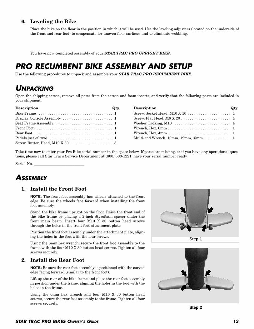
1. Install the Front FootNOTE: The front foot assembly has wheels attached to the frontedge. Be sure the wheels face forward when installing the frontfoot assembly.
Stand the bike frame upright on the floor. Raise the front end ofthe bike frame by placing a 2-inch Styrofoam spacer under thefront main beam. Insert four M10 X 30 button head screwsthrough the holes in the front foot attachment plate.
Position the front foot assembly under the attachment plate, align-ing the holes in the foot with the four screws.
Using the 6mm hex wrench, secure the front foot assembly to theframe with the four M10 X 30 button head screws. Tighten all fourscrews securely.
2. Install the Rear FootNOTE: Be sure the rear foot assembly is positioned with the curvededge facing forward (similar to the front foot).
Lift up the rear of the bike frame and place the rear foot assemblyin position under the frame, aligning the holes in the foot with theholes in the frame.
Using the 6mm hex wrench and four M10 X 30 button headscrews, secure the rear foot assembly to the frame. Tighten all fourscrews securely.
Description Qty.Bike Frame . . . . . . . . . . . . . . . . . . . . . . . . . . . . . . . . . . 1Display Console Assembly . . . . . . . . . . . . . . . . . . . . . . . 1Seat Frame Assembly . . . . . . . . . . . . . . . . . . . . . . . . . . 1Front Foot . . . . . . . . . . . . . . . . . . . . . . . . . . . . . . . . . . . 1Rear Foot . . . . . . . . . . . . . . . . . . . . . . . . . . . . . . . . . . . . 1Pedals (set of two) . . . . . . . . . . . . . . . . . . . . . . . . . . . . . 1Screw, Button Head, M10 X 30 . . . . . . . . . . . . . . . . . . . 8
Description Qty.Screw, Socket Head, M10 X 10 . . . . . . . . . . . . . . . . . . . . 4Screw, Flat Head, M6 X 20 . . . . . . . . . . . . . . . . . . . . . . . 4Washer, Locking, M10 . . . . . . . . . . . . . . . . . . . . . . . . . . 4Wrench, Hex, 6mm . . . . . . . . . . . . . . . . . . . . . . . . . . . . . 1Wrench, Hex, 4mm . . . . . . . . . . . . . . . . . . . . . . . . . . . . . 1Multi-end Wrench, 10mm, 12mm,15mm . . . . . . . . . . . . 1
Step 1
Step 2
14 STAR TRAC PRO BIKES OWNER’S GUIDE
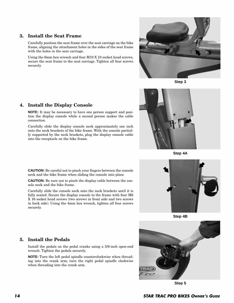
3. Install the Seat FrameCarefully position the seat frame over the seat carriage on the bikeframe, aligning the attachment holes in the sides of the seat framewith the holes in the seat carriage.
Using the 6mm hex wrench and four M10 X 10 socket head screws,secure the seat frame to the seat carriage. Tighten all four screwssecurely.
4. Install the Display ConsoleNOTE: It may be necessary to have one person support and posi-tion the display console while a second person makes the cableconnection.
Carefully slide the display console neck approximately one inchonto the neck brackets of the bike frame. With the console partial-ly supported by the neck brackets, plug the display console cableinto the receptacle on the bike frame.
CAUTION: Be careful not to pinch your fingers between the consoleneck and the bike frame when sliding the console into place.
CAUTION: Be sure not to pinch the display cable between the con-sole neck and the bike frame.
Carefully slide the console neck onto the neck brackets until it isfully seated. Secure the display console to the frame with four M6X 16 socket head screws (two screws in front side and two screwsin back side). Using the 4mm hex wrench, tighten all four screwssecurely.
5. Install the PedalsInstall the pedals on the pedal cranks using a 5/8-inch open-endwrench. Tighten the pedals securely.
NOTE: Turn the left pedal spindle counterclockwise when thread-ing into the crank arm; turn the right pedal spindle clockwisewhen threading into the crank arm.
Step 3
Step 4A
Step 4B
Step 5
STAR TRAC PRO BIKES OWNER’S GUIDE 15
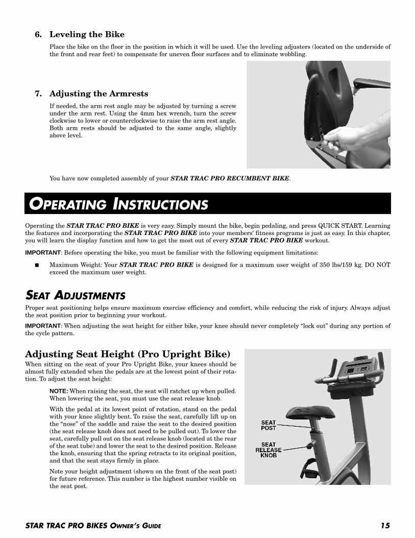
6. Leveling the BikePlace the bike on the floor in the position in which it will be used. Use the leveling adjusters (located on the underside ofthe front and rear feet) to compensate for uneven floor surfaces and to eliminate wobbling.
7. Adjusting the ArmrestsIf needed, the arm rest angle may be adjusted by turning a screwunder the arm rest. Using the 4mm hex wrench, turn the screwclockwise to lower or counterclockwise to raise the arm rest angle.Both arm rests should be adjusted to the same angle, slightlyabove level.
You have now completed assembly of your STAR TRAC PRO RECUMBENT BIKE.
OPERATING INSTRUCTIONSOperating the STAR TRAC PRO BIKE is very easy. Simply mount the bike, begin pedaling, and press QUICK START. Learningthe features and incorporating the STAR TRAC PRO BIKE into your members' fitness programs is just as easy. In this chapter,you will learn the display function and how to get the most out of every STAR TRAC PRO BIKE workout.
IMPORTANT: Before operating the bike, you must be familiar with the following equipment limitations:
■ Maximum Weight: Your STAR TRAC PRO BIKE is designed for a maximum user weight of 350 lbs/159 kg. DO NOTexceed the maximum user weight.
SEAT ADJUSTMENTSProper seat positioning helps ensure maximum exercise efficiency and comfort, while reducing the risk of injury. Always adjustthe seat position prior to beginning your workout.
IMPORTANT: When adjusting the seat height for either bike, your knee should never completely “lock out” during any portion ofthe cycle pattern.
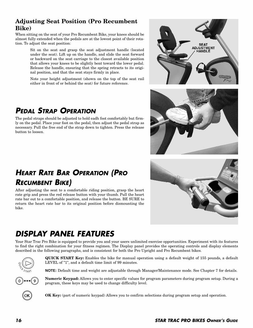
Adjusting Seat Height (Pro Upright Bike)When sitting on the seat of your Pro Upright Bike, your knees should bealmost fully extended when the pedals are at the lowest point of their rota-tion. To adjust the seat height:
NOTE: When raising the seat, the seat will ratchet up when pulled.When lowering the seat, you must use the seat release knob.
With the pedal at its lowest point of rotation, stand on the pedalwith your knee slightly bent. To raise the seat, carefully lift up onthe “nose” of the saddle and raise the seat to the desired position(the seat release knob does not need to be pulled out). To lower theseat, carefully pull out on the seat release knob (located at the rearof the seat tube) and lower the seat to the desired position. Releasethe knob, ensuring that the spring retracts to its original position,and that the seat stays firmly in place.
Note your height adjustment (shown on the front of the seat post)for future reference. This number is the highest number visible onthe seat post.
16 STAR TRAC PRO BIKES OWNER’S GUIDE
Adjusting Seat Position (Pro Recumbent Bike)When sitting on the seat of your Pro Recumbent Bike, your knees should bealmost fully extended when the pedals are at the lowest point of their rota-tion. To adjust the seat position:
Sit on the seat and grasp the seat adjustment handle (locatedunder the seat). Lift up on the handle, and slide the seat forwardor backward on the seat carriage to the closest available positionthat allows your knees to be slightly bent toward the lower pedal.Release the handle, ensuring that the spring retracts to its origi-nal position, and that the seat stays firmly in place.
Note your height adjustment (shown on the top of the seat raileither in front of or behind the seat) for future reference.
PEDAL STRAP OPERATIONThe pedal straps should be adjusted to hold eadh foot comfortably but firm-ly on the pedal. Place your foot on the pedal, then adjust the pedal strap asnecessary. Pull the free end of the strap down to tighten. Press the releasebutton to loosen.
HEART RATE BAR OPERATION (PRO
RECUMBENT BIKE)After adjusting the seat to a comfortable riding position, grasp the heartrate grip and press the red release button with your thumb. Pull the heartrate bar out to a comfortable position, and release the button. BE SURE toreturn the heart rate bar to its original position before dismounting thebike.
DISPLAY PANEL FEATURESYour Star Trac Pro Bike is equipped to provide you and your users unlimited exercise opportunities. Experiment with its featuresto find the right combination for your fitness regimen. The Display panel provides the operating controls and display elementsdescribed in the following paragraphs, and is consistent for both the Pro Upright and Pro Recumbent bikes.
QUICK START Key: Enables the bike for manual operation using a default weight of 155 pounds, a defaultLEVEL of "1", and a default time limit of 99 minutes.
NOTE: Default time and weight are adjustable through Manager/Maintenance mode. See Chapter 7 for details.
Numeric Keypad: Allows you to enter specific values for program parameters during program setup. During aprogram, these keys may be used to change difficulty level.
OK Key: (part of numeric keypad) Allows you to confirm selections during program setup and operation.
ARROW Key: (part of numeric keypad) Allows you to make corrections to values entered during program setup.
Increase LEVEL Key: Increases the difficulty level from 1 (least difficulty) to 20 (greatest difficulty), in one-levelincrements. Current level setting is shown in the LEVEL display window.
Decrease LEVEL Key: Decreases the difficulty level from 20 (greatest difficulty) to 1 (least difficulty), in one-level increments. Current level setting is shown in the LEVEL display window.
Fan Key: Allows you to control the speed of the personal cooling fan, either OFF, HIGH or LOW.
SCROLL Keys: Scrolls the upper and lower data information windows between the three available data displays.
Preset Program Keys: Allow you to access a desired preset workout program.
Upper Data Information Window: Shows current and aggregate data related to your workout. Pressing the associated SCROLL
key scrolls between the following displays:
■ CALORIES - Shows your aggregate caloric expenditure thus far in your workout.■ CAL/HR - Shows your average caloric expenditure per hour thus far in your workout.■ WATTS - Shows your aggregate watts expenditure thus far in your workout.
Lower Data Information Window: Shows current and aggregate data related to your workout. Pressing the associated SCROLL
key scrolls between the following displays:
■ DISTANCE - Shows the total number of miles or kilometers you have ridden thus far.■ SPEED - Shows the speed at which you are currently pedaling, in miles-per-hour or kilometers-per-hour.■ METS - Shows your aggregate METS expenditure thus far in your workout.
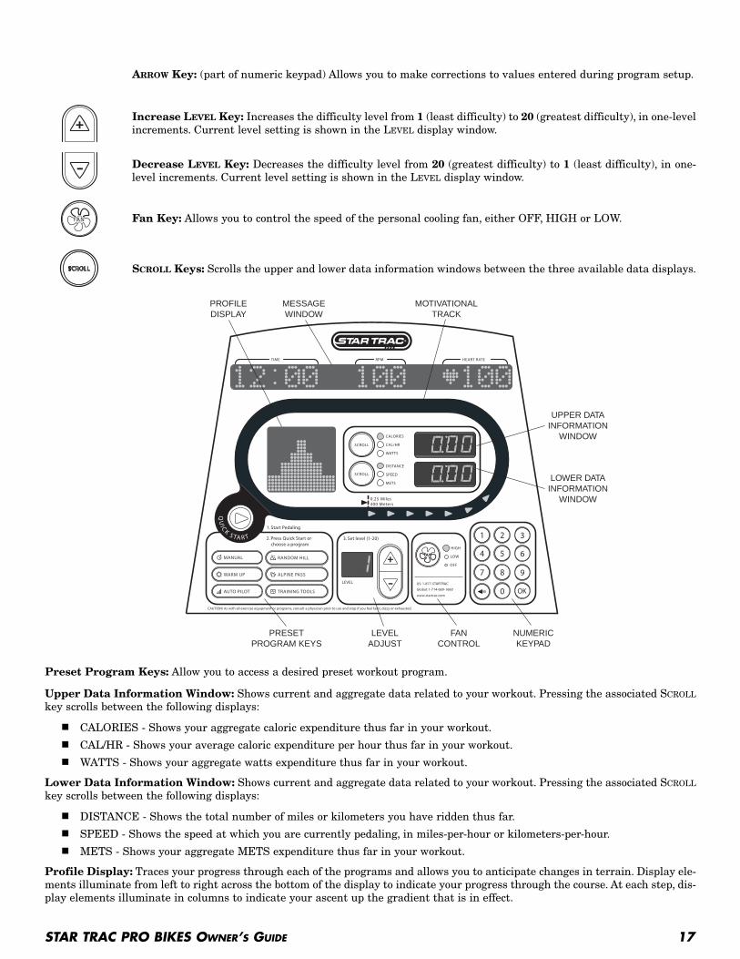
Profile Display: Traces your progress through each of the programs and allows you to anticipate changes in terrain. Display ele-ments illuminate from left to right across the bottom of the display to indicate your progress through the course. At each step, dis-play elements illuminate in columns to indicate your ascent up the gradient that is in effect.
STAR TRAC PRO BIKES OWNER’S GUIDE 17
PRESETPROGRAM KEYS
LEVELADJUST
NUMERICKEYPAD
UPPER DATAINFORMATION
WINDOW
LOWER DATAINFORMATION
WINDOW
MESSAGEWINDOW
MOTIVATIONALTRACK
PROFILEDISPLAY
FANCONTROL
18 STAR TRAC PRO BIKES OWNER’S GUIDE
Motivational Track: Shows your progress counter clockwise around 1/4-mile (400-meter) course, starting from the bottom center.
Message Window: Provides informational messages, prompts during program setup, feedback during your workout, notificationwhen your workout is complete, and scrolling summarized workout data after your workout. During your workout, the InformationWindow shows the following data:
■ TIME - Shows the duration of your workout thus far in minutes and seconds.
■ RPM - Shows the current speed at which you are pedaling in revolutions-per-minute.
■ HEART RATE - Shows your current heart rate in beats-per-minute (BPM) while wearing the heart rate strap or graspingthe heart rate grips.
Depending on the program completed and bike settings as set in Manager/Maintenance mode, workout data may include:
HINTS AND TIPS FOR GETTING STARTEDThe following hints and tips will assist in training your users to maximize the fitness benefits of your STAR TRAC PRO BIKE.
■ Pedal at a rate that feels comfortable and most natural, yet is sufficiently vigorous to get a good cardio workout.
■ Try different pedaling rhythms. In manual operation, vary your pedaling speed from slow to fast, then back to slow.As you become more comfortable with your bike, try pedaling faster, varying the resistance LEVEL, or using the presetprograms.
■ Watch the Graphic Display to anticipate terrain changes. When you use the preset programs, the display showschanges in terrain as tall or short columns.
VIEWING WORKOUT DATA DURING A PROGRAMWorkout data is shown in three windows on the Pro Bike Display Panel: the Message Window (located at the top of the DisplayPanel) and the Upper and Lower Data Information Windows (located inside the Motivational Track, to the right of the Profile Window).
Information shown in the Message Window during a workout includes elapsed time, revolutions per minute (RPM’s), and heartrate (HR), when in use. After the workout is complete, workout summary information is shown in the Message Window.
The Message Window also displays important instructions and cues throughout the workout.
The Upper and Lower Data Information Windows also display information during a workout.
To view workout data during your workout:
1. Press the Upper Data Display Window SCROLL key to view the following workout data (the current data display is indi-cated by an LED next to the parameter name):
■ CALORIES - Shows your aggregate caloric expenditure thus far in your workout.
■ CAL/HR - Shows your average caloric expenditure per hour thus far in your workout.
■ WATTS - Shows your current watts expenditure during that specific time of the workout.
2. Press the Lower Data Display Window SCROLL key to view the following workout data (the current data display is indi-cated by an LED next to the parameter name):
■ DISTANCE - Shows the total number of miles or kilometers you have ridden thus far.
■ SPEED - Shows the speed at which you are currently pedaling, in miles-per-hour or kilometers-per-hour.
■ METS - Shows your current METS expenditure during that specific time of the workout.
■ Time consumed
■ Calories expended
■ Distance traveled - miles or kilometers
■ Average speed - mph or kph
■ Average calories expended per hour
■ Average minutes per mile/kilometer
■ Average RPM
■ Average watts
■ Average METS
■ Average heart rate
STAR TRAC PRO BIKES OWNER’S GUIDE 19
COOLDOWN CYCLEIn most programs, once you have completed your workout, the bike enters a two-minute Cooldown cycle.
NOTE: The Pro Bike software is programmed to properly decrease pedaling resistance to provide a cooldown.
To operate the bike during Cooldown:
1. You can adjust the difficulty LEVEL during Cooldown.
■ Use the keys to enter a difficulty LEVEL (from 1 to 20); or press the or key, as desired, to increase ordecrease the difficulty LEVEL in 1 unit increments.
■ When the desired difficulty LEVEL has been entered, press the key to accept the displayed LEVEL.
2. When the Cooldown cycle ends, your workout summary displays in the Information Window. If you wish to exit theCooldown cycle before it ends automatically, stop pedaling.
USING THE PERSONAL FANThe STAR TRAC PRO BIKE is equipped with a built-in personal fan to increase your comfort during a workout. you can controlthe fan speed during your workout.
To operate the personal fan:
■ Press the key, as necessary, to cycle the personal fan from OFF to HIGH to LOW to OFF. An LED indicator lights toshow the currently selected fan speed.
■ The fan remains set at the set speed if you pause your program.
■ The fan turns off automatically if you exit your workout, or when you complete your workout program.
HEART RATE MONITORINGHeart rate monitoring allows you to determine if your workout is too challenging or not challenging enough. Monitoring heart rateis easy with the STAR TRAC PRO BIKE. You may use a heart rate strap (not provided with the Pro Bike), or you can simplygrasp the silver contact heart rate grips.
NOTE: The Heart Rate monitor is not a medical test, nor is it designed as a medical test. It is simply a guide to target heart ratetraining. Please consult with your physician prior to engaging in any strenuous physical activity.
IMPORTANT: The manufacturer does not warrant the heart rate system performance on this product, as the heart rate systemperformance varies, based on a user's physiology, fitness level, age, method of use and other factors. Furthermore, the heart ratesystem is not for medical use.
CONTACT HEART RATE MONITORINGYou may use the heart rate contact grips to automatically check your heart rate. Just follow these steps.
1. Grasp the stainless steel heart rate contact grips; you do not have to squeeze tightly.
2. It may take from 30 to 60 seconds for the heart rate system to acquire and display your heart rate.
3. When your heart rate has been acquired, the indicator, and your heart rate in beats per minute (BPM) displays in theHEART RATE field of the Information Window.
4. Release the Heart Rate grips if you wish to remove your heart rate reading from the display.
CHEST STRAP HEART RATE MONITORINGYou may use the heart rate strap to automatically check your heart rate. Just follow these steps:
1. Before beginning your workout, or during a pause, moisten the back of the transmitter on the heart rate strap (notincluded). Place the strap snugly around your chest with the transmitter resting directly over your sternum.
20 STAR TRAC PRO BIKES OWNER’S GUIDE
2. When your heart rate has been acquired, the indicator and your heart rate in beats per minute (BPM) display in theHEART RATE field of the Information Window.
3. Remove the heart rate strap, if you wish to remove your heart rate reading from the display.
NOTE: The performance of the transmitter may be affected by body types, body oils, metal in clothing, and outside electrical inter-ference. Always be sure that the transmitter and skin are in good contact. Avoid operating other electrical equipment near yourtreadmill when you use the heart rate strap.
QUICK START Quick Start lets you begin your workout by simply pressing one key, or by pedaling for approximately 10 seconds without press-ing any key. Quick Start uses a default weight of 155 pounds (70 kg), a difficulty LEVEL of 1, and a time limit of 99 minutes. YOUcontrol resistance LEVEL during the entire program.
To operate the Quick Start program:
1. Mount the bike (please refer to “SEAT ADJUSTMENTS” section), begin pedaling, and press the QUICK START key.
2. If desired, you can use the personal fan during your workout (see “Using the Personal Fan” for details).
3. You can adjust the resistance LEVEL during the program, using either of the following methods.
■ Use the keys to enter a resistance level (from 1 to 20). When the desired level has been entered, press the
key to confirm the resistance level.
■ Press the or key, as desired, to increase or decrease the resistance LEVEL in 1 unit increments.
4. You can scroll through workout data during the program (see “Viewing Workout Data During a Program” for details).
5. If you wish to pause the program, stop pedaling. The bike will enter pause mode and display your workout results for oneentire cycle.
6. When you have reached your workout goal, the bike enters the Cooldown cycle (see “Cooldown Cycle” for details). If youwish to exit the program before you have reached your workout goal, stop pedaling and allow the Pause timer to expire.
If you wish to skip the Cooldown cycle, press the key to view your workout summary.
PRESET PROGRAMSThe STAR TRAC PRO BIKES offer 10 preset programs to add variety and challenge to your workout, including the advancedTRAINING TOOLS function that provides four cardio-intensive training programs and a Fitness Test.
Pre-set programs include:
Allows the user to pre-program a time goal and user weight. Resistance is determined by the user during the pro-gram.
Seven-minute program with three resistance level settings designed to properly warm-up the muscles prior toworking out.
Allows the user to positively increase the level of resistance by increasing pedaling speed (rpm’s). No keys topress with this one!
200 varied hill programs that allow the user to pre-program a time goal, user weight and program level (from 1to 20).
An intense 3-peak ride that allows the user to pre-program a time goal, user weight and program level (from 1to 20).
Our advanced program that offers the user the ability to train in specific HR zones or watt ranges, or to completethe integrated Fitness Test.
STAR TRAC PRO BIKES OWNER’S GUIDE 21
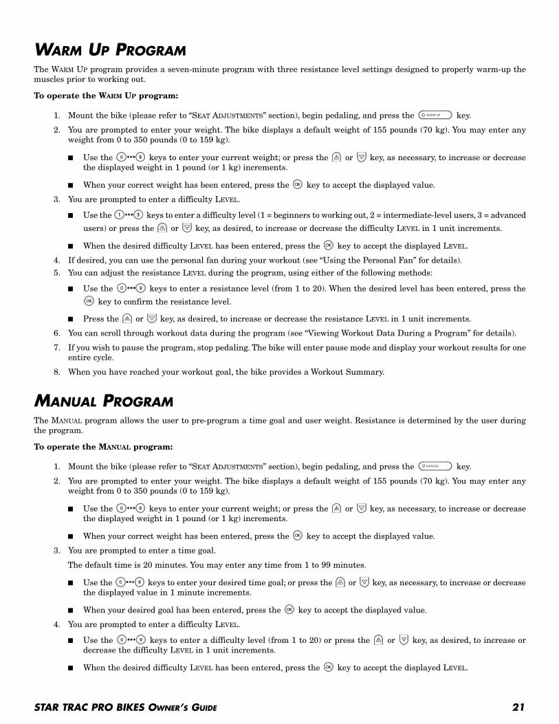
WARM UP PROGRAMThe WARM UP program provides a seven-minute program with three resistance level settings designed to properly warm-up themuscles prior to working out.
To operate the WARM UP program:
1. Mount the bike (please refer to “SEAT ADJUSTMENTS” section), begin pedaling, and press the key.
2. You are prompted to enter your weight. The bike displays a default weight of 155 pounds (70 kg). You may enter anyweight from 0 to 350 pounds (0 to 159 kg).
■ Use the keys to enter your current weight; or press the or key, as necessary, to increase or decreasethe displayed weight in 1 pound (or 1 kg) increments.
■ When your correct weight has been entered, press the key to accept the displayed value.
3. You are prompted to enter a difficulty LEVEL.
■ Use the keys to enter a difficulty level (1 = beginners to working out, 2 = intermediate-level users, 3 = advanced
users) or press the or key, as desired, to increase or decrease the difficulty LEVEL in 1 unit increments.
■ When the desired difficulty LEVEL has been entered, press the key to accept the displayed LEVEL.
4. If desired, you can use the personal fan during your workout (see “Using the Personal Fan” for details).
5. You can adjust the resistance LEVEL during the program, using either of the following methods:
■ Use the keys to enter a resistance level (from 1 to 20). When the desired level has been entered, press the
key to confirm the resistance level.
■ Press the or key, as desired, to increase or decrease the resistance LEVEL in 1 unit increments.
6. You can scroll through workout data during the program (see “Viewing Workout Data During a Program” for details).
7. If you wish to pause the program, stop pedaling. The bike will enter pause mode and display your workout results for oneentire cycle.
8. When you have reached your workout goal, the bike provides a Workout Summary.
MANUAL PROGRAMThe MANUAL program allows the user to pre-program a time goal and user weight. Resistance is determined by the user duringthe program.
To operate the MANUAL program:
1. Mount the bike (please refer to “SEAT ADJUSTMENTS” section), begin pedaling, and press the key.
2. You are prompted to enter your weight. The bike displays a default weight of 155 pounds (70 kg). You may enter anyweight from 0 to 350 pounds (0 to 159 kg).
■ Use the keys to enter your current weight; or press the or key, as necessary, to increase or decreasethe displayed weight in 1 pound (or 1 kg) increments.
■ When your correct weight has been entered, press the key to accept the displayed value.
3. You are prompted to enter a time goal.
The default time is 20 minutes. You may enter any time from 1 to 99 minutes.
■ Use the keys to enter your desired time goal; or press the or key, as necessary, to increase or decreasethe displayed value in 1 minute increments.
■ When your desired goal has been entered, press the key to accept the displayed value.
4. You are prompted to enter a difficulty LEVEL.
■ Use the keys to enter a difficulty level (from 1 to 20) or press the or key, as desired, to increase ordecrease the difficulty LEVEL in 1 unit increments.
■ When the desired difficulty LEVEL has been entered, press the key to accept the displayed LEVEL.

22 STAR TRAC PRO BIKES OWNER’S GUIDE
5. If desired, you can use the personal fan during your workout (see “Using the Personal Fan” for details).
6. You can adjust the resistance LEVEL during the program, using either of the following methods:
■ Use the keys to enter a resistance level (from 1 to 20). When the desired level has been entered, press the
key to confirm the resistance level.
■ Press the or key, as desired, to increase or decrease the resistance LEVEL in 1 unit increments.
7. You can scroll through workout data during the program (see “Viewing Workout Data During a Program” for details).
8. If you wish to pause the program, stop pedaling. The bike will enter pause mode and display your workout results for oneentire cycle.
9. When you have reached your workout goal, the bike enters the Cooldown cycle (see “Cooldown Cycle” for details). If youwish to exit the program before you have reached your workout goal, stop pedaling and allow the Pause timer to expire.
AUTO PILOT PROGRAMThe AUTO PILOT program allows the user to positively increase the level of resistance by increasing pedaling speed (rpm’s). No keysto press with this one!
To operate the AUTO PILOT program:
1. Mount the bike (please refer to “SEAT ADJUSTMENTS” section), begin pedaling, and press the key.
2. If desired, you can use the personal fan during your workout (see “Using the Personal Fan” for details).
3. You can increase the resistance LEVEL during the program by increasing your pedaling speed. Decreasing your pedalingspeed will lower the resistance LEVEL.
4. You can scroll through workout data during the program (see “Viewing Workout Data During a Program” for details).
5. If you wish to pause the program, stop pedaling. The bike will enter pause mode and display your workout results for oneentire cycle.
6. When you have reached your workout goal, the bike enters the Cooldown cycle (see “Cooldown Cycle” for details). If youwish to exit the program before you have reached your workout goal, stop pedaling and allow the Pause timer to expire.
RANDOM HILL / ALPINE PASS PROGRAMSThe RANDOM HILL program offers 200 varied hill programs that allow the user to pre-program a time goal, user weight and programlevel (from 1 to 20). The ALPINE PASS program is an intense 3-peak ride that allows the user to pre-program a time goal, user weightand program level (from 1 to 20).
To operate the RANDOM HILL or ALPINE PASS program:
1. Mount the bike (please refer to “SEAT ADJUSTMENTS” section), begin pedaling, and press the or key,as desired.
2. You are prompted to enter your weight. The bike displays a default weight of 155 pounds (70 kg). You may enter anyweight from 0 to 350 pounds (0 to 159 kg).
■ Use the keys to enter your current weight; or press the or key, as necessary, to increase or decreasethe displayed weight in 1 pound (or 1 kg) increments.
■ When your correct weight has been entered, press the key to accept the displayed value.
3. You are prompted to enter a time goal. The bike displays a default time of 20 minutes. You may enter any time from 5 to99 minutes.
■ Use the keys to enter the desired time goal, or press the or key, as necessary, to increase or decreasethe displayed value in 1 minute increments.
■ When your desired time goal has been entered, press the key to accept the displayed value.
4. You are prompted to enter a difficulty LEVEL.
■ Use the keys to enter a difficulty level (from 1 to 20) or press the or key, as desired, to increase ordecrease the difficulty LEVEL in 1 unit increments.
■ When the desired difficulty LEVEL has been entered, press the key to accept the displayed LEVEL.
STAR TRAC PRO BIKES OWNER’S GUIDE 23
5. If desired, you can use the personal fan during your workout (see “Using the Personal Fan” for details).
6. You can adjust the resistance LEVEL during the program, using either of the following methods:
■ Use the keys to enter a resistance level (from 1 to 20). When the desired level has been entered, press the
key to confirm the resistance level.
■ Press the or key, as desired, to increase or decrease the resistance LEVEL in 1 unit increments.
7. You can scroll through workout data during the program (see “Viewing Workout Data During a Program” for details).
8. If you wish to pause the program, stop pedaling. The bike will enter pause mode and display your workout results for oneentire cycle.
9. When you have reached your workout goal, the bike enters the Cooldown cycle (see “Cooldown Cycle” for details). If youwish to exit the program before you have reached your workout goal, stop pedaling and allow the Pause timer to expire.
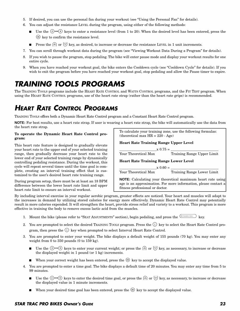
TRAINING TOOLS PROGRAMSThe TRAINING TOOLS programs include the HEART RATE CONTROL and WATTS CONTROL programs, and the FIT TEST program. Whenusing the HEART RATE CONTROL programs, use of the heart rate strap (rather than the heart rate grips) is recommended.
HEART RATE CONTROL PROGRAMSTRAINING TOOLS offers both a Dynamic Heart Rate Control program and a Constant Heart Rate Control program.
NOTE: For best results, use a heart rate strap. If user is wearing a heart rate strap, the bike will automatically use the data fromthe heart rate strap.
To operate the Dynamic Heart Rate Control pro-gram:
This heart rate feature is designed to gradually elevateyour heart rate to the upper end of your selected trainingrange, then gradually decrease your heart rate to thelower end of your selected training range by dynamicallycontrolling pedaling resistance. During the workout, thiscycle will repeat several times until the time goal is com-plete, creating an interval training effect that is cus-tomized to the user’s desired heart rate training range.
During program setup, there must be at least an 18 BPMdifference between the lower heart rate limit and upperheart rate limit to ensure an interval workout.
By including interval exercise in your regular aerobic program, greater effects are noticed. Your heart and muscles will adapt tothe increases in demand by utilizing stored calories for energy more effectively. Dynamic Heart Rate Control may potentiallyresult in more calories expended. It will strengthen the heart, provide stress relief and variety to a workout. This program is moreeffective in training the body to remove excess lactic acid from the muscles.
1. Mount the bike (please refer to “SEAT ADJUSTMENTS” section), begin pedaling, and press the key.
2. You are prompted to select the desired TRAINING TOOLS program. Press the key to select the Heart Rate Control pro-
gram, then press the key when prompted to select Interval Heart Rate Control.
3. You are prompted to enter your weight. The bike displays a default weight of 155 pounds (70 kg). You may enter anyweight from 0 to 350 pounds (0 to 159 kg).
■ Use the keys to enter your current weight; or press the or key, as necessary, to increase or decreasethe displayed weight in 1 pound (or 1 kg) increments.
■ When your correct weight has been entered, press the key to accept the displayed value.
4. You are prompted to enter a time goal. The bike displays a default time of 20 minutes. You may enter any time from 5 to99 minutes.
■ Use the keys to enter the desired time goal, or press the or key, as necessary, to increase or decreasethe displayed value in 1 minute increments.
■ When your desired time goal has been entered, press the key to accept the displayed value.
To calculate your training zone, use the following formulas:(theoretical max HR = 220 - Age)
Heart Rate Training Range Upper Level
_____________________x 0.75 = ___________________________Your Theoretical Max Training Range Upper Limit
Heart Rate Training Range Lower Level
_____________________x 0.60 = ___________________________Your Theoretical Max Training Range Lower Limit
NOTE: Calculating your theoretical maximum heart rate usingage is an approximation. For more information, please contact afitness professional or doctor.

24 STAR TRAC PRO BIKES OWNER’S GUIDE
5. You are prompted to enter your age.
■ Use the keys to enter your age, or press the or key, as necessary, to increase or decrease the displayedvalue in 1 year increments.
■ When your correct age has been entered, press the key to accept the displayed value.
6. You are prompted to enter an upper heart rate limit. The bike displays a default upper heart rate limit that is based on80% of your theoretical maximum heart rate (220 BPM - age). You may enter any value from ___ to ___ BPM.
■ Use the keys to enter an upper heart rate limit, or press the or key, as desired, to increase or decreasethe heart rate limit in 1 BPM increments.
■ When the desired upper heart rate limit has been entered, press the key to accept the displayed value.
7. You are prompted to enter a lower heart rate limit. The bike displays a default lower heart rate limit that is based on60% of your theoretical maximum heart rate (220 BPM - age). You may enter any value from ___ to ___ BPM.
■ Use the keys to enter a lower heart rate limit, or press the or key, as desired, to increase or decreasethe heart rate limit in 1 BPM increments.
■ When the desired lower heart rate limit has been entered, press the key to accept the displayed value.
8. If desired, you can use the personal fan during your workout (see “Using the Personal Fan” for details).
9. You can scroll through workout data during the program (see “Viewing Workout Data During a Program” for details).
10. If you wish to pause the program, stop pedaling. The bike will enter pause mode and display your workout results for oneentire cycle.
11. When you have reached your workout goal, the bike enters the Cooldown cycle (see “Cooldown Cycle” for details). If youwish to exit the program before you have reached your workout goal, stop pedaling and allow the Pause timer to expire.
To operate the Constant Heart Rate Control program:
This heart rate feature is designed to maintain your heart rate at a constant level by controlling pedaling resistance and prompt-ing you to pedal at a specified RPM. Please note that your heart rate may vary above and below your target heart rate during thisprogram.
1. Mount the bike (please refer to “SEAT ADJUSTMENTS” section), begin pedaling, and press the key.
2. You are prompted to select the desired TRAINING TOOLS program. Press the key to select the Heart Rate Control pro-
gram, then press the key when prompted to select Constant Heart Rate Control.
3. You are prompted to enter your weight. The bike displays a default weight of 155 pounds (70 kg). You may enter anyweight from 0 to 350 pounds (0 to 159 kg).
■ Use the keys to enter your current weight; or press the or key, as necessary, to increase or decreasethe displayed weight in 1 pound (or 1 kg) increments.
■ When your correct weight has been entered, press the key to accept the displayed value.
4. You are prompted to enter a time goal. The bike displays a default time of 20 minutes. You may enter any time from 5 to99 minutes.
■ Use the keys to enter the desired time goal, or press the or key, as necessary, to increase or decreasethe displayed value in 1 minute increments.
■ When your desired time goal has been entered, press the key to accept the displayed value.
5. You are prompted to enter your age.
■ Use the keys to enter your age, or press the or key, as necessary, to increase or decrease the displayedvalue in 1 year increments.
■ When your correct age has been entered, press the key to accept the displayed value.
6. You are prompted to enter a target heart rate. The bike displays a default target heart rate that is based on 70% of yourtheoretical maximum heart rate (220 BPM - age). You may enter any value from ___ to ___ BPM.
■ Use the keys to enter your target heart rate, or press the or key, as desired, to increase or decreasethe target heart rate in 1 BPM increments.
■ When the desired target heart rate has been entered, press the key to accept the displayed value.

STAR TRAC PRO BIKES OWNER’S GUIDE 25
7. If desired, you can use the personal fan during your workout (see “Using the Personal Fan” for details).
8. You can scroll through workout data during the program (see “Viewing Workout Data During a Program” for details).
9. If you wish to pause the program, stop pedaling.The bike will enter pause mode and display your workout results for oneentire cycle.
10. When you have reached your workout goal, the bike enters the Cooldown cycle (see “Cooldown Cycle” for details). If youwish to exit the program before you have reached your workout goal, stop pedaling and allow the Pause timer to expire.
WATTS PROGRAMSTRAINING TOOLS offers both a Dynamic Watts Interval program and a Constant Watts program. Watts are a measurement of workloadthat are dependant upon the resistance of the bike and the user’s RPM.
To operate the Watts Interval program:
This feature is designed to alternate your watts expenditure to the upper end of your selected training range, then graduallydecrease it to the lower end of your selected training range by dynamically controlling pedaling resistance and prompting you topedal at a specified RPM. During the workout, this cycle will repeat several times, creating an interval training effect that is cus-tomized to the user’s desired watts training range.
1. Mount the bike (please refer to “SEAT ADJUSTMENTS” section), begin pedaling, and press the key.
2. You are prompted to select the desired TRAINING TOOLS program. Press the key to select the Watts program, then press
the key when prompted to select Watts Interval.
3. You are prompted to enter your weight. The bike displays a default weight of 155 pounds (70 kg). You may enter anyweight from 0 to 350 pounds (0 to 159 kg).
■ Use the keys to enter your current weight; or press the or key, as necessary, to increase or decreasethe displayed weight in 1 pound (or 1 kg) increments.
■ When your correct weight has been entered, press the key to accept the displayed value.
4. You are prompted to enter a time goal. The bike displays a default time of 20 minutes. You may enter any time from 5 to99 minutes.
■ Use the keys to enter the desired time goal, or press the or key, as necessary, to increase or decreasethe displayed value in 1 minute increments.
■ When your desired time goal has been entered, press the key to accept the displayed value.
5. You are prompted to enter your age.
■ Use the keys to enter your age, or press the or key, as necessary, to increase or decrease the displayedvalue in 1 year increments.
■ When your correct age has been entered, press the key to accept the displayed value.
6. You are prompted to enter an upper watts limit. The bike displays a default upper watts limit of 300 watts. You may enterany value from 50 to 600 watts.
■ Use the keys to enter an upper watts limit, or press the or key, as desired, to increase or decrease thewatts limit in 1 watt increments.
■ When the desired upper heart rate limit has been entered, press the key to accept the displayed value.
7. You are prompted to enter a lower watts limit. The bike displays a default lower watts limit of 200 watts. You may enterany value from 50 to 600 watts.
■ Use the keys to enter a lower watts limit, or press the or key, as desired, to increase or decrease thewatts limit in 1 watt increments.
■ When the desired lower watts limit has been entered, press the key to accept the displayed value.
8. If desired, you can use the personal fan during your workout (see “Using the Personal Fan” for details).
9. You can scroll through workout data during the program (see “Viewing Workout Data During a Program” for details).
10. If you wish to pause the program, stop pedaling. The bike will enter pause mode and display your workout results for oneentire cycle.
11. When you have reached your workout goal, the bike enters the Cooldown cycle (see “Cooldown Cycle” for details). If youwish to exit the program before you have reached your workout goal, stop pedaling and allow the Pause timer to expire.
26 STAR TRAC PRO BIKES OWNER’S GUIDE
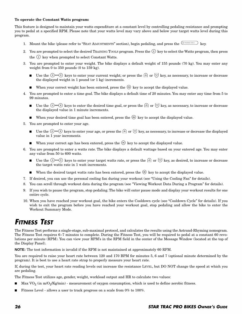
To operate the Constant Watts program:
This feature is designed to maintain your watts expenditure at a constant level by controlling pedaling resistance and promptingyou to pedal at a specified RPM. Please note that your watts level may vary above and below your target watts level during thisprogram.
1. Mount the bike (please refer to “SEAT ADJUSTMENTS” section), begin pedaling, and press the key.
2. You are prompted to select the desired TRAINING TOOLS program. Press the key to select the Watts program, then press
the key when prompted to select Constant Watts.
3. You are prompted to enter your weight. The bike displays a default weight of 155 pounds (70 kg). You may enter anyweight from 0 to 350 pounds (0 to 159 kg).
■ Use the keys to enter your current weight; or press the or key, as necessary, to increase or decreasethe displayed weight in 1 pound (or 1 kg) increments.
■ When your correct weight has been entered, press the key to accept the displayed value.
4. You are prompted to enter a time goal. The bike displays a default time of 20 minutes. You may enter any time from 5 to99 minutes.
■ Use the keys to enter the desired time goal, or press the or key, as necessary, to increase or decreasethe displayed value in 1 minute increments.
■ When your desired time goal has been entered, press the key to accept the displayed value.
5. You are prompted to enter your age.
■ Use the keys to enter your age, or press the or key, as necessary, to increase or decrease the displayedvalue in 1 year increments.
■ When your correct age has been entered, press the key to accept the displayed value.
6. You are prompted to enter a watts rate. The bike displays a default wattage based on your entered age. You may enterany value from 50 to 600 watts.
■ Use the keys to enter your target watts rate, or press the or key, as desired, to increase or decreasethe target watts rate in 1 watt increments.
■ When the desired target watts rate has been entered, press the key to accept the displayed value.
7. If desired, you can use the personal cooling fan during your workout (see “Using the Cooling Fan” for details).
8. You can scroll through workout data during the program (see "Viewing Workout Data During a Program” for details).
9. If you wish to pause the program, stop pedaling. The bike will enter pause mode and display your workout results for oneentire cycle.
10. When you have reached your workout goal, the bike enters the Cooldown cycle (see “Cooldown Cycle” for details). If youwish to exit the program before you have reached your workout goal, stop pedaling and allow the bike to enter theWorkout Summary Mode.
FITNESS TESTThe Fitness Test performs a single-stage, sub-maximal protocol, and calculates the results using the Astrand-Rhyming nomogram.The Fitness Test requires 6~7 minutes to complete. During the Fitness Test, you will be required to pedal at a constant 60 revo-lutions per minute (RPM). You can view your RPM’s in the RPM field in the center of the Message Window (located at the top ofthe Display Panel).
NOTE: The test information is invalid if the RPM is not maintained at approximately 60 RPM.
You are required to raise your heart rate between 120 and 170 BPM for minutes 5, 6 and 7 (optional minute determined by theprogram). It is best to use a heart rate strap to properly measure your heart rate.
If, during the test, your heart rate reading levels out increase the resistance LEVEL, but DO NOT change the speed at which youare pedaling.
The Fitness Test utilizes age, gender, weight, workload output and HR to calculate two values:
■ Max VO2 (in m/O2/Kg/min) - measurement of oxygen consumption, which is used to define aerobic fitness.
■ Fitness Level - allows a user to track progress on a scale from 0% to 100%.

STAR TRAC PRO BIKES OWNER’S GUIDE 27
NOTE: You must wear the heart rate strap during the FITNESS TEST to monitor your heart rate.
To operate the Fitness Test program:
1. Mount the bike (please refer to “SEAT ADJUSTMENTS” section), begin pedaling, and press the key.
2. You are prompted to select the desired TRAINING TOOLS program. Press the key when prompted to select Fitness Test.
3. You are prompted to enter your weight. The bike displays a default weight of 155 pounds (70 kg). You may enter anyweight from 0 to 350 pounds (0 to 159 kg).
■ Use the keys to enter your current weight; or press the or key, as necessary, to increase or decreasethe displayed weight in 1 pound (or 1 kg) increments.
■ When your correct weight has been entered, press the key to accept the displayed value.
4. You are prompted to enter your gender.
■ Press the key to set the gender to “male”, press the key to set the gender to “female”.
■ When your correct gender has been entered, press the key to accept the displayed value.
5. You are prompted to enter your age.
■ Use the keys to enter your age, or press the or key, as necessary, to increase or decrease the displayedvalue in 1 year increments.
■ When your correct age has been entered, press the key to accept the displayed value.
6. The FITNESS TEST runs for 6~7 minutes. During the Fitness Test, you must maintain pedaling speed at a constant 60RPM.
During the test, you may adjust the difficulty LEVEL at any time.
7. If desired, you can use the personal cooling fan during your workout (see “Using the Cooling Fan” for details).
8. When the test is completed, the bike enters the Cooldown cycle (see “Cooldown Cycle” for details). If you wish to exit theprogram before you have reached your workout goal, stop pedaling and allow the Pause timer to expire.

28 STAR TRAC PRO BIKES OWNER’S GUIDE
With durable, high performance components, STAR TRAC PRO BIKES are designed for heavy usage with minimal maintenancerequired. To keep your bike in top condition, Star Trac strongly recommends performing the regular daily, weekly and monthlypreventive maintenance routines outlined below. Any unusual symptoms, such as a loud continuous noise during operation, shouldbe reported to STAR TRAC PRODUCT SUPPORT DEPARTMENT at (800) 503-1221, or USA 1-714-669-1660.
DAILY MAINTENANCE■ Remove excessive accumulations of dust, dirt, and other substances by using a clean, soft cloth and a non-abrasive liquid clean-
er, such as Formula 409TM or FANTASTIKTM. Wipe down the exterior of the display panel, handlebars, seat, pedals, shrouds andheart rate grips.
NOTE: DO NOT spray the cleaner directly onto the display panel or heart rate grips.
WEEKLY MAINTENANCEPerform the following services each week:
■ Vacuum the floor under and around the bike. Move the bike to another spot, if necessary, to vacuum thoroughly.
■ Inspect the display panel mounting screws for security, and retighten if necessary.
■ Inspect the display panel keypads for wear.
MONTHLY MAINTENANCEPerform the following services each month, or as needed:
■ Check that the seat, pedals and shrouds are secure.
■ Tighten the pedals onto their respective pedal cranks using a 5/8-inch open end wrench.
PREVENTATIVE MAINTENANCE
MANAGER / MAINTENANCE MODEAfter using your STAR TRAC PRO BIKE for a period of time, you may wish to change some of its settings.
MANAGER MODEThe Manager Settings allow you to query and modify the basic settings of your bike. To enter Manager Settings:
1. Press and hold the , and keys together.
2. A beep will sound and “MANAGER SETTINGS” will display momentarily in the Information Window.
3. Release all keys. “SERIAL NUMBER” will display in the Information Window.
NOTE: The system will automatically exit Manager Settings if no key is pressed for 30 seconds.
The following keys are used to modify MANAGER SETTINGS:
Upper and Lower Data Information Window SCROLL Keys: Display the next and previous parameters,respectively. Keys will repeat if held.
Increase and Decrease LEVEL Keys: Adjust the value of the displayed parameter up and down, respectively,in increments of 1 unit . These keys do not save the new value - see OK Key below.
OK Key: Updates (saves) the value of the displayed parameter in Flash memory, and exits Manager Mode.
NOTE: To exit Manager Mode without saving any values or settings, press the QUICK START key.
STAR TRAC PRO BIKES OWNER’S GUIDE 29
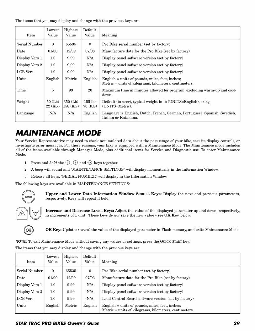
The items that you may display and change with the previous keys are:
MAINTENANCE MODEYour Service Representative may need to check accumulated data about the past usage of your bike, test its display controls, orinvestigate error messages. For these reasons, your bike is equipped with a Maintenance Mode. The Maintenance mode includesall of the items available through Manager Mode, plus additional items for Service and Diagnostic use. To enter MaintenanceMode:
1. Press and hold the , and keys together.
2. A beep will sound and “MAINTENANCE SETTINGS” will display momentarily in the Information Window.
3. Release all keys. “SERIAL NUMBER” will display in the Information Window.
The following keys are available in MAINTENANCE SETTINGS:
Upper and Lower Data Information Window SCROLL Keys: Display the next and previous parameters,respectively. Keys will repeat if held.
Increase and Decrease LEVEL Keys: Adjust the value of the displayed parameter up and down, respectively,in increments of 1 unit . These keys do not save the new value - see OK Key below.
OK Key: Updates (saves) the value of the displayed parameter in Flash memory, and exits Maintenance Mode.
NOTE: To exit Maintenance Mode without saving any values or settings, press the QUICK START key.
The items that you may display and change with the previous keys are:
Lowest Highest DefaultItem Value Value Value Meaning
Serial Number 0 65535 0 Pro Bike serial number (set by factory)
Date 01/00 12/99 07/03 Manufacture date for the Pro Bike (set by factory)
Display Vers 1 1.0 9.99 N/A Display panel software version (set by factory)
Display Vers 2 1.0 9.99 N/A Display panel software version (set by factory)
LCB Vers 1.0 9.99 N/A Display panel software version (set by factory)
Units English Metric English English = units of pounds, miles, feet, inches;Metric = units of kilograms, kilometers, centimeters.
Time 5 99 20 Maximum time in minutes allowed for program, excluding warm-up and cool-down.
Weight 50 (Lb) 350 (Lb) 155 lbs Default (to user), typical weight in lb (UNITS=English), or kg 22 (KG) 158 (KG) 70 (KG) (UNITS=Metric).
Language N/A N/A English Language is English, Dutch, French, German, Portuguese, Spanish, Swedish,Italian or Katakana.
Lowest Highest DefaultItem Value Value Value Meaning
Serial Number 0 65535 0 Pro Bike serial number (set by factory)
Date 01/00 12/99 07/03 Manufacture date for the Pro Bike (set by factory)
Display Vers 1 1.0 9.99 N/A Display panel software version (set by factory)
Display Vers 2 1.0 9.99 N/A Display panel software version (set by factory)
LCB Vers 1.0 9.99 N/A Load Control Board software version (set by factory)
Units English Metric English English = units of pounds, miles, feet, inches;Metric = units of kilograms, kilometers, centimeters.

30 STAR TRAC PRO BIKES OWNER’S GUIDE
Lowest Highest DefaultItem Value Value Value Meaning
Time 5 99 20 Maximum time in minutes allowed for program, excluding warm-up and cool-down.
Weight 50 (Lb) 350 (Lb) 155 lbs Default (to user), typical weight in lb (UNITS=English), or kg 22 (KG) 158 (KG) 70 (KG) (UNITS=Metric).
Language N/A N/A English Language in English, Dutch, French, German, Portuguese, Spanish, Swedish,Italian or Katakana.
Model N/A N/A PB-UB PB-UB = Pro Bike - UprightPB-RB = Pro Bike - RecumbentNAT-RUNNER = Natural Runner
OPER Hours 0 65535 0 Total operating hours
BATT Hours 0 65535 0 Total battery use hours
Quick Start 0 65535 0 Number of times the Quick Start program was run since last reset.
Manual 0 65535 0 Number of times the Manual Program was run since last reset.
Warm Up 0 65535 0 Number of times the Warm Up Program was run since last reset.
Auto Pilot 0 65535 0 Number of times the Auto Pilot Program was run since last reset.
IHR Program 0 65535 0 Number of times the Interval Heart Rate Control Program was run since lastreset.
CHR Program 0 65535 0 Number of times the Constant Heart Rate Control Program was run sincelast reset.
WI Program 0 65535 0 Number of times the Watts Interval Program was run since last reset.
CW Program 0 65535 0 Number of times the Continuous Watts Program was run since last reset.
Fit Test 0 65535 0 Number of times the Fitness Test Program was run since last reset.
Alpine 0 65535 0 Number of times the Alpine Pass Program was run since last reset.
Rndm Prog 0 65535 0 Number of times the Random Hill Program was run since last reset.
Over Temp 0 65535 0 Number of times an “Over Temperature” condition occurred since last reset.
No Temp 0 65535 0 Number of times a “No Temperature” condition occurred since last reset.
Low Batt 0 65535 0 Number of times a “Low Battery” condition occurred since last reset.
Comm Lost 0 65535 0 Number of times a “Communication Lost” condition occurred since last reset.
Key Down 0 65535 0 Number of times a “Key Down” condition occurred since last reset.
LED Test N/A N/A N/A Access to integral LED test function (for use by authorized MaintenanceTechnician).
Keypad Test N/A N/A N/A Access to integral keypad test function (for use by authorized MaintenanceTechnician).
Heart Rate N/A N/A N/A Access to integral heart rate system test function (for use by authorized Test Maintenance Technician).
Measurements N/A N/A N/A Access to integral Measurements function (for use by authorizedMaintenance Technician).
Auto Status N/A N/A OFF Turns on/off the unsolicited status of the CSAFE feature.

STAR TRAC PRO BIKES OWNER’S GUIDE 31
STAR TRAC PRO BIKES perform a self-test at the beginning of every workout. If a problem is detected, a message displaysbefore or after the workout, depending on the nature of the problem. Star Trac recommends that you refer your questions aboutyour STAR TRAC PRO BIKE operation and suspected malfunctions to Star Trac’s Service Hotline at (800) 503-1221, or USA 1-714-669-1660.
START-UP SERVICE MESSAGESThe following messages are displayed at the beginning of a workout if the associated problem is detected during self-test.
■ Key Down - One or more keys on the display panel are stuck in the “on” position. This can occur if a user presses keysbefore the system is turned on. Call Star Trac Product Support for assistance if the Key Down message continues to dis-play.
TROUBLESHOOTING
REGULATORY INFORMATION
TO BE PROVIDED WHEN AVAILABLE

STAR TRAC14410 Myford Road
Irvine, California 92606Telephone: (800) 228-6635, (714) 669-1660
Fax: (714) 508-3303http://www.startrac.com
Part Number XXX-XXXX, August 2003
LCD Attachment
Installation andService Manual

2
1
Table of Contents
Parts List ................................................................................................2
Hardware Kits ........................................................................................3
Bike, Cross Trainer and Stepper Start ....................................................4
Steps in Assembling the Bracket ............................................................5
Installation Instructions (Bike, Cross Trainer & Stepper) .......................6
Installation Instructions (Bike, Cross Trainer & Stepper) Cont’d ............7
Installation Instructions (Bike, Cross Trainer & Stepper) Cont’d ............8
Installation Instructions (Bike, Cross Trainer & Stepper) Cont’d ............9
Final Installation (Bike, Cross Trainer & Stepper) .................................10
Treadmill Start ......................................................................................11
Steps in Assembling the Bracket ..........................................................12
Treadmill Installation Instructions .......................................................13
Treadmill Installation Instructions (Cont’d) .........................................14
Treadmill Installation Instructions (Cont’d) .........................................15
Treadmill Installation Instructions (Cont’d) .........................................16
Treadmill Installation Instructions (Cont’d) .........................................17
Final Installation (Treadmill) .................................................................18
Maintenance Requirements ..................................................................19
Club Owner Guide ................................................................................20
Club Owner Guide (Cont’d) ..................................................................21
A/V Installer’s Guide .............................................................................22
A/V Installer’s Guide (Cont’d) ..............................................................23
A/V Installer’s Guide (Cont’d) ..............................................................24
A/V Installer’s Guide (Cont’d) ..............................................................25
A/V Installer’s Guide (Cont’d) ..............................................................26
A/V Install - Wire Management ............................................................27

22
All Kits include:
Before installing the TV bracket verify that you have the proper kit according to the list above and that all the parts are included. If any of the items are missing call StarTrac at 800-503-1221 to order a replacement kit.
Parts List (All Machines)
Product Model ...................................................................................Kit Part NumberPro Tread .......................................................................................................715-3628Pro Stepper ....................................................................................................711-3178Pro Bike Upright .............................................................................................718-5079Pro Bike Recumbent ......................................................................................720-0087CrossTrainer ...................................................................................................721-1093
Neck Mounting support assembly
(Crossbow)
Mounting braces
(Wings)
Monitor Interface
(Gooseneck)
Clamp top and bottom with pad Wire management
*Not included in kit 715-3628 (Pro Tread)
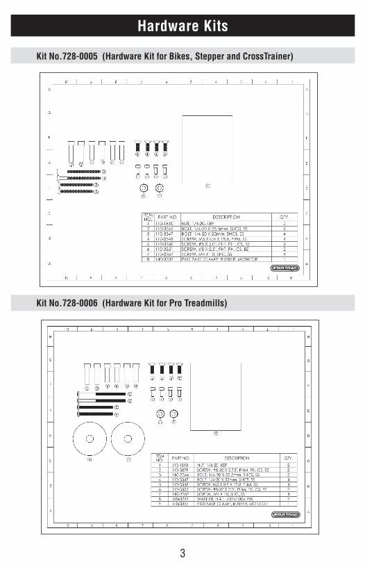
33
Hardware Kits
Kit No.728-0005 (Hardware Kit for Bikes, Stepper and CrossTrainer)
Kit No.728-0006 (Hardware Kit for Pro Treadmills)
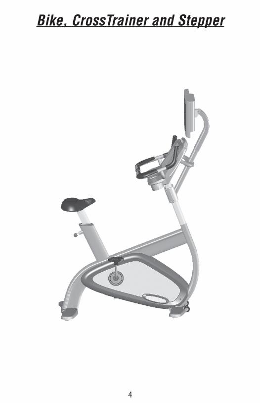
4
Bike, CrossTrainer and Stepper

55
Steps in Assembling the BracketBike, CrossTrainer and Stepper
This pictorial view shows the assembly of the TV bracket in. The following pages describe the install process.
(Final assembled bracket)
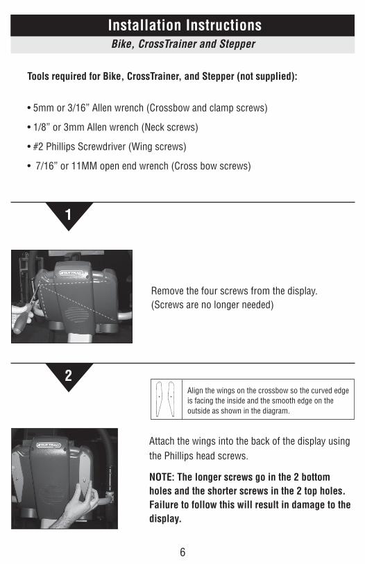
66
Installation Instructions
Tools required for Bike, CrossTrainer, and Stepper (not supplied):
• 5mm or 3/16” Allen wrench (Crossbow and clamp screws)
• 1/8” or 3mm Allen wrench (Neck screws)
• #2 Phillips Screwdriver (Wing screws)
• 7/16” or 11MM open end wrench (Cross bow screws)
Bike, CrossTrainer and Stepper
1
Remove the four screws from the display.(Screws are no longer needed)
2
Attach the wings into the back of the display using the Phillips head screws.
NOTE: The longer screws go in the 2 bottom holes and the shorter screws in the 2 top holes. Failure to follow this will result in damage to the display.
Align the wings on the crossbow so the curved edge is facing the inside and the smooth edge on the outside as shown in the diagram.
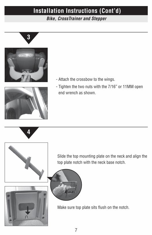
77
Installation Instructions (Cont’d)Bike, CrossTrainer and Stepper
3
- Attach the crossbow to the wings.
- Tighten the two nuts with the 7/16” or 11MM open end wrench as shown.
4
Slide the top mounting plate on the neck and align the top plate notch with the neck base notch.
Make sure top plate sits fl ush on the notch.
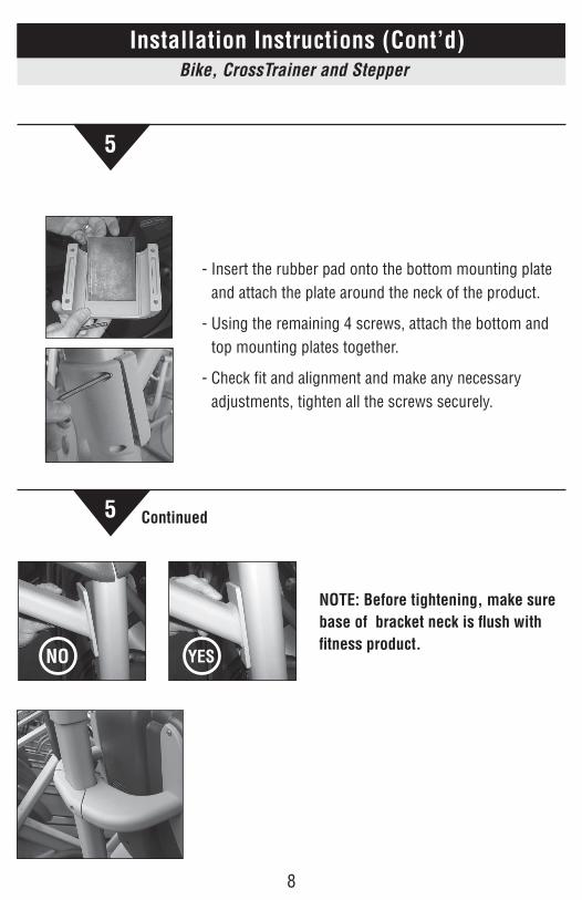
88
Installation Instructions (Cont’d)Bike, CrossTrainer and Stepper
5
NOTE: Before tightening, make sure base of bracket neck is flush with fitness product.
NO YES
5
- Insert the rubber pad onto the bottom mounting plate and attach the plate around the neck of the product.
- Using the remaining 4 screws, attach the bottom and top mounting plates together.
- Check fit and alignment and make any necessary adjustments, tighten all the screws securely.
Continued
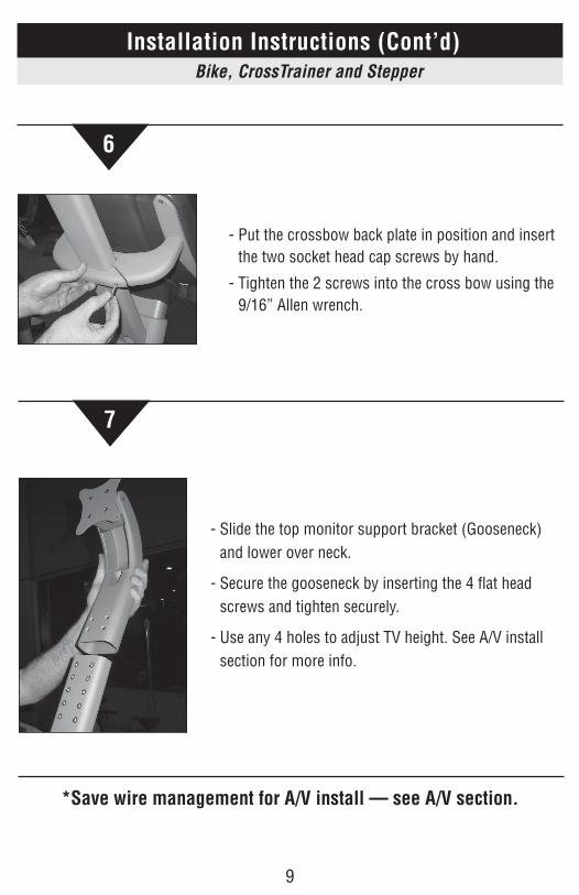
99
Bike, CrossTrainer and Stepper
7
- Slide the top monitor support bracket (Gooseneck) and lower over neck.
- Secure the gooseneck by inserting the 4 flat head screws and tighten securely.
- Use any 4 holes to adjust TV height. See A/V install section for more info.
Installation Instructions (Cont’d) Installation Instructions (Cont’d)Bike, CrossTrainer and Stepper
- Put the crossbow back plate in position and insert the two socket head cap screws by hand.
- Tighten the 2 screws into the cross bow using the 9/16” Allen wrench.
6
*Save wire management for A/V install — see A/V section.
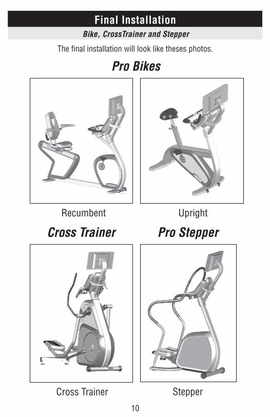
1010
The final installation will look like theses photos.
Final InstallationBike, CrossTrainer and Stepper
Pro Bikes
Pro StepperCross Trainer
Recumbent
Cross Trainer Stepper
Upright
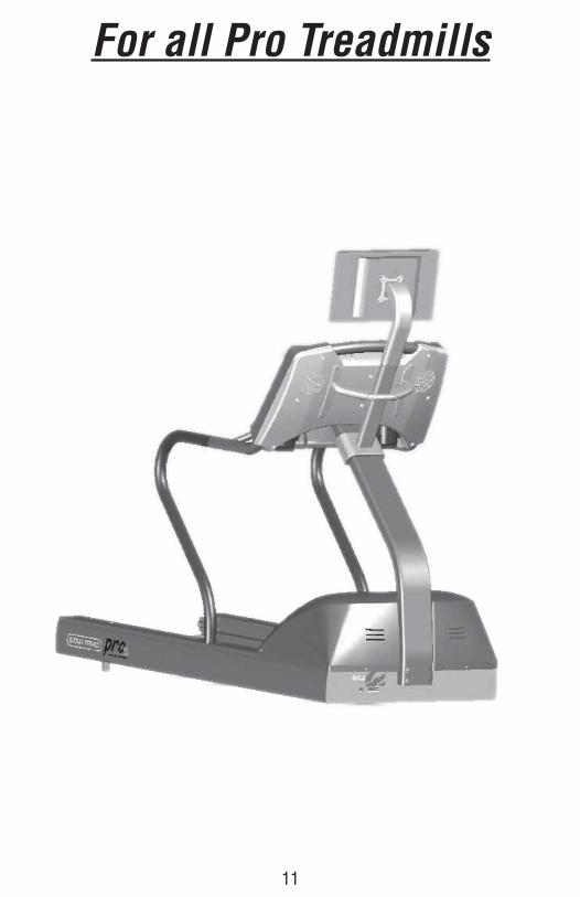
Bike, CrossTrainer and Stepper
11
For all Pro Treadmills
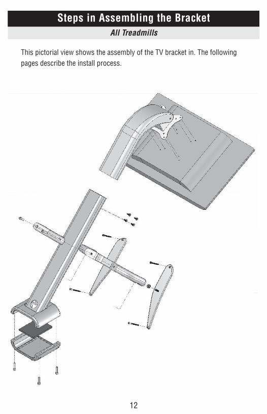
1212
All Treadmills
Steps in Assembling the Bracket
This pictorial view shows the assembly of the TV bracket in. The following pages describe the install process.
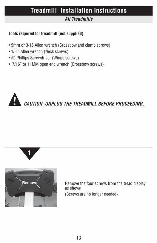
1313
1
Remove the four screws from the tread display as shown.(Screws are no longer needed)
Treadmill Installation Instructions
Tools required for treadmill (not supplied):
• 5mm or 3/16 Allen wrench (Crossbow and clamp screws)• 1/8 “ Allen wrench (Neck screws)• #2 Phillips Screwdriver (Wings screws) • 7/16” or 11MM open end wrench (Crossbow screws)
CAUTION: UNPLUG THE TREADMILL BEFORE PROCEEDING.
All Treadmills
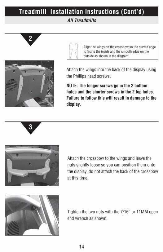
1414
2
Attach the wings into the back of the display using the Phillips head screws.
NOTE: The longer screws go in the 2 bottom holes and the shorter screws in the 2 top holes. Failure to follow this will result in damage to the display.
Align the wings on the crossbow so the curved edge is facing the inside and the smooth edge on the outside as shown in the diagram.
All Treadmills
Treadmill Installation Instructions (Cont’d)
3
Attach the crossbow to the wings and leave the nuts slightly loose so you can position them onto the display, do not attach the back of the crossbow at this time.
Tighten the two nuts with the 7/16” or 11MM open end wrench as shown.
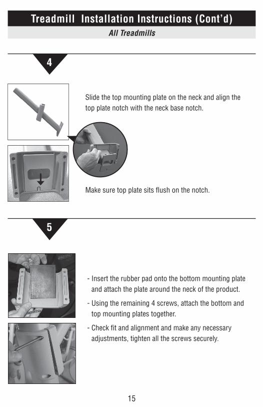
1515
4
5
All Treadmills
Treadmill Installation Instructions (Cont’d)
Slide the top mounting plate on the neck and align the top plate notch with the neck base notch.
Make sure top plate sits fl ush on the notch.
- Insert the rubber pad onto the bottom mounting plate and attach the plate around the neck of the product.
- Using the remaining 4 screws, attach the bottom and top mounting plates together.
- Check fi t and alignment and make any necessary adjustments, tighten all the screws securely.
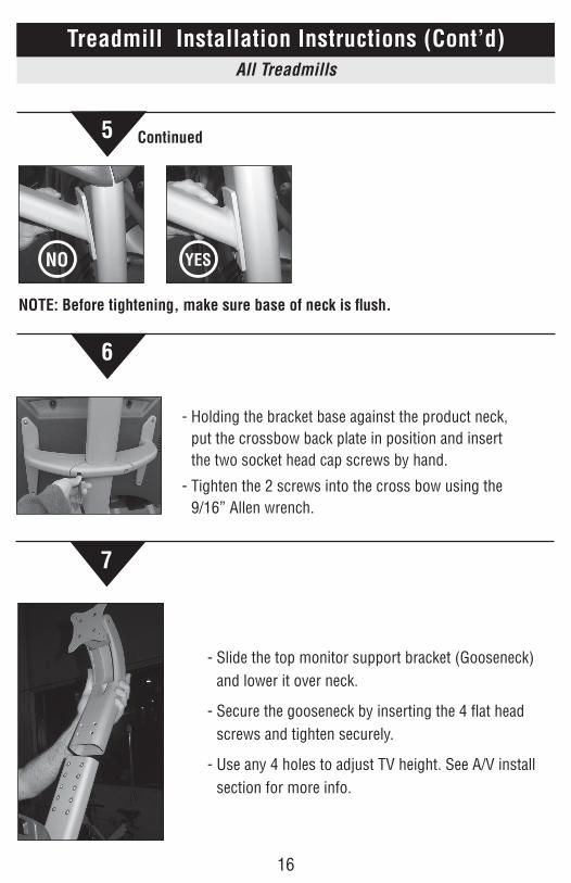
1616
All Treadmills
Treadmill Installation Instructions (Cont’d)
7
- Slide the top monitor support bracket (Gooseneck) and lower it over neck.
- Secure the gooseneck by inserting the 4 flat head screws and tighten securely.
- Use any 4 holes to adjust TV height. See A/V install section for more info.
- Holding the bracket base against the product neck, put the crossbow back plate in position and insert the two socket head cap screws by hand.
- Tighten the 2 screws into the cross bow using the 9/16” Allen wrench.
NOTE: Before tightening, make sure base of neck is flush.
NO YES
5 Continued
6
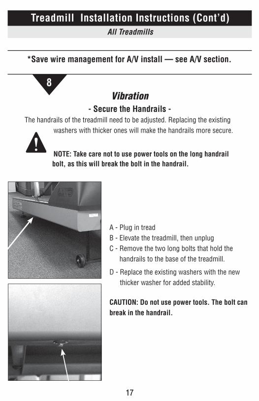
171717
*Save wire management for A/V install — see A/V section.
Vibration- Secure the Handrails -
The handrails of the treadmill need to be adjusted. Replacing the existing washers with thicker ones will make the handrails more secure.
NOTE: Take care not to use power tools on the long handrail bolt, as this will break the bolt in the handrail.
8
A - Plug in treadB - Elevate the treadmill, then unplugC - Remove the two long bolts that hold the
handrails to the base of the treadmill.
D - Replace the existing washers with the new thicker washer for added stability.
CAUTION: Do not use power tools. The bolt can break in the handrail.
All Treadmills
Treadmill Installation Instructions (Cont’d)
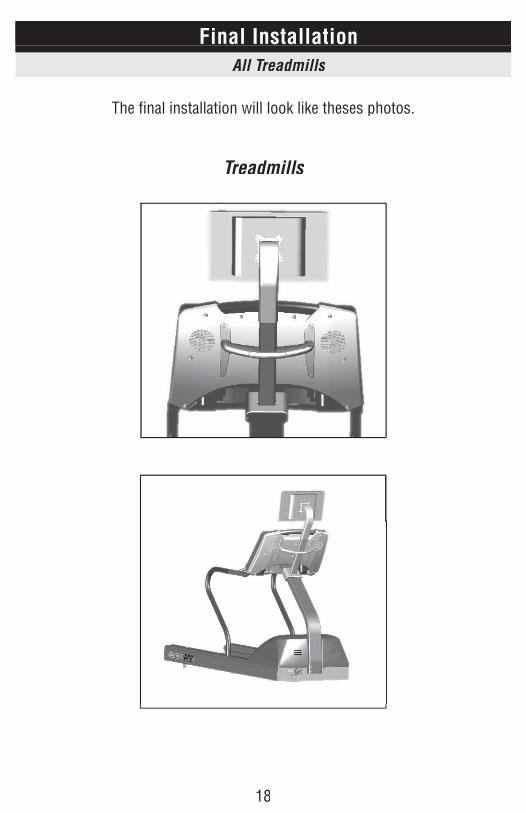
18
All Treadmills
The fi nal installation will look like theses photos.
Treadmills
Final Installation

191919
All Treadmills
The final installation will look like theses photos.
Final Installation Maintenance Requirements
Star Trac strongly recommends performing the regular daily, weekly, and monthly preventive maintenance routines outlined below. If any items need replacement call STAR TRAC PRODUCT SUPPORT DEPARTMENT at (800) 503-1221, or USA 1-714-669-1660. To order replacement part,s we will need the serial number and model number.
D = Daily W = Weekly M = Monthly (depending on the amount of use, some procedures may need to be performed more frequently)
Preventative Maintenance D W M Procedure
The daily maintenance of the monitor bracket will determine the life of the monitor bracket by how consistently it is performed. • Wipe down the monitor bracket with a soft cloth. • Never use abrasive cleaning liquids or oil based cleaner, ammonia or alcohol when
wiping down the monitor bracket.
The Weekly maintenance should focus on the overall performance of the monitor bracket. During this portion of the maintenance, look for vibration and possible loose assemblies. • Inspect each monitor bracket for loose parts, bolts and nuts. Adjust as necessary. • Remove any monitor brackets that are deemed unsafe. • Test the tilt mechanism of the monitor to make sure it stays at the desired angle for
viewing.
The monthly maintenance check should be a comprehensive inspection of the overall frame and main assembly components of the monitor bracket. • Inspect all areas for proper adjustments • Inspect all parts to determine damage which will require possible part replacement.
202020
Club Owner Guide
Star Trac Fitness supplies the mounting bracket that allows an LCD TV to be attached to our fitness products. Star Trac does not supply the LCD TV equipment or the supporting wire and power installation support. As a club owner, you will be responsible for coordinating the LCD TV installation through several outside vendors. It is the club owner’s responsibility to select and engage an outside Audio Visual (A/V) installation firm to provide TVs, controllers, and wiring in the ceiling/floor, and to install each piece of A/V function on the fitness equipment. The biggest challenge for a club owner is learning where the responsibility of one vendor ends, and another begins. During the installation process, each vendor has the following basic responsibilities: • Cable or Satellite Operator – Will bring the TV signal into your facility.
Typically will install equipment in a closet or back room. The Cable/SAT installer will typically NOT install wires or support installation to each individual piece of equipment.
• A/V installer – Involved in the sale of the individual TV units and responsible for the installation from the video source to each piece of equipment. Installers may specify power and construction requirements, but will not actually do the AC or building construction work themselves.
• Power and Electrical Contractor – Will be used to install AC power outlets at each piece of fitness equipment to power the TVs. This contractor is typically hired by the club owner to execute a power plan developed by the A/V installer.
• General or Construction Contractor – If any special wall or conduit needs to be installed to facilitate wire management, a building contractor will be hired by the club owner to execute a plan developed by the A/V installer.
Bike, CrossTrainer, Stepper and Pro Tread

212121
Typical installations require both a coax (with the video signal) and a power supply cable run to each individual piece of fitness equipment. AC power outlet requirements will certainly be the responsibility of the club owner hiring a local electrical sub-contractor. When discussing an installation with an A/V firm, you will want to address the following concerns: • What drawings and floor plans will the A/V installer be providing to you? Will
these plans include reference to the AC power requirements for the electrical and construction sub-contractors you hire?
• How are the wires going to run to each piece of equipment? In the ceiling? In the floor? Will the wires being run be hidden or dressed in a manor that is safe and aesthetically pleasing? Will a knee-wall be required? Who will specify the power and construction requirements for this wall?
• What video signal enhancers or amplifiers are required to show TV on all your fitness products? Multiple TVs will require a good working knowledge of video signal distribution techniques; otherwise, the picture will be snowy or fuzzy.
• Who is responsible when a TV is not working, or if the TV signal is of poor quality? What is the installer’s warrantee and on-site support plan? What is the vendor’s response time for repair?
• Several A/V companies specialize in fitness-only AV installation. No matter who you select, always ask for references. If possible, talk to another club owner and try to discover any pit-falls that you can avoid in your installation.
Club Owner Guide (cont.)Bike, CrossTrainer, Stepper and Pro Tread
2222
As an A/V Installer, you will be tasked with running the TV power and video to each unit. You should provide the club owner with a clear definition of your role in theinstallation process, and what other sub-contractors the club owner will require to complete the installation. When installing and wiring TVs on Star Trac brackets, there are several areas you should be aware of:
Mounting the TV
• The TV will be mounted to the Star Trac bracket using the provided 75mm and 100mm VESA standard mounting plate.
• I n the bracket hardware kit, (4) 4mm x 10 screws are provided to attach the TV to the bracket.
• The installer is responsible for bringing all the required hardware to mount the TV.
• It is impossible for Star Trac to provide all possible mounting hardware for every 3rd party product on the market.
• As an installer, you are required to provide longer or shorter screws due to variations in TV manufacturer mounting requirements.
• If your A/V solution includes a DVD player or other 3rd party bracket or adapter, the installer will be required to bring all the needed mounting hardware, and verify compatibility with our bracket.
• Please request a bracket sample from Star Trac before performing a large onsite installation as to verify a proper fit of the A/V solution you are supplying.
Adjusting the TV Height
• The bracket gooseneck allows the height of the TV to be adjusted up and down by selecting a different set of threaded holes in the bracket neck.
• Typically you will want to lower the TV to a position just above the fitness equipment display console.
• Do not lower the TV to the point where it actually touches the fitness equipment display console.
A/V Installer’s GuideBike, CrossTrainer, Stepper and Pro Tread
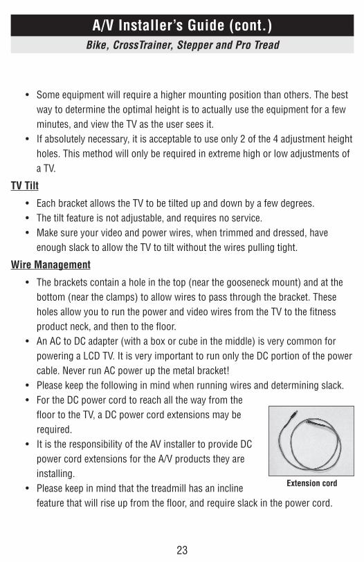
2323
• Some equipment will require a higher mounting position than others. The best way to determine the optimal height is to actually use the equipment for a few minutes, and view the TV as the user sees it.
• If absolutely necessary, it is acceptable to use only 2 of the 4 adjustment height holes. This method will only be required in extreme high or low adjustments of a TV.
TV Tilt
• Each bracket allows the TV to be tilted up and down by a few degrees. • The tilt feature is not adjustable, and requires no service. • Make sure your video and power wires, when trimmed and dressed, have
enough slack to allow the TV to tilt without the wires pulling tight.
Wire Management
• The brackets contain a hole in the top (near the gooseneck mount) and at the bottom (near the clamps) to allow wires to pass through the bracket. These holes allow you to run the power and video wires from the TV to the fitness product neck, and then to the floor.
• An AC to DC adapter (with a box or cube in the middle) is very common for powering a LCD TV. It is very important to run only the DC portion of the power cable. Never run AC power up the metal bracket!
• Please keep the following in mind when running wires and determining slack. • For the DC power cord to reach all the way from the
floor to the TV, a DC power cord extensions may be required.
• It is the responsibility of the AV installer to provide DC power cord extensions for the A/V products they are installing.
• Please keep in mind that the treadmill has an incline feature that will rise up from the floor, and require slack in the power cord.
A/V Installer’s Guide (cont.)Bike, CrossTrainer, Stepper and Pro Tread
Extension cord
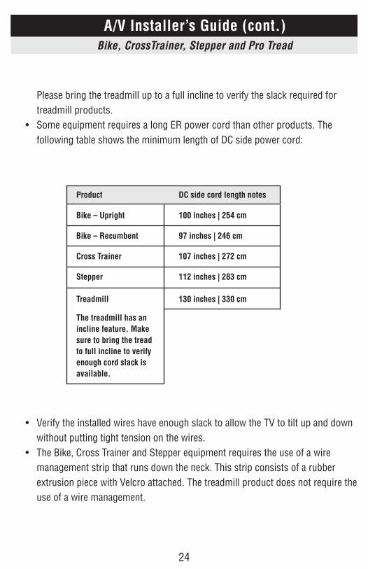
2424
Please bring the treadmill up to a full incline to verify the slack required for treadmill products.
• Some equipment requires a long ER power cord than other products. The following table shows the minimum length of DC side power cord:
• Verify the installed wires have enough slack to allow the TV to tilt up and down without putting tight tension on the wires.
• The Bike, Cross Trainer and Stepper equipment requires the use of a wire management strip that runs down the neck. This strip consists of a rubber extrusion piece with Velcro attached. The treadmill product does not require the use of a wire management.
A/V Installer’s Guide (cont.)Bike, CrossTrainer, Stepper and Pro Tread
Product DC side cord length notes
Bike – Upright 100 inches | 254 cm
Bike – Recumbent 97 inches | 246 cm
Cross Trainer 107 inches | 272 cm
Stepper 112 inches | 283 cm
Treadmill 130 inches | 330 cm
The treadmill has an incline feature. Make sure to bring the tread to full incline to verify enough cord slack is available.
2525
• Bike Wires • The wires will exit the bracket down onto the fitness product neck. • Do not use tie–wraps around the fitness product neck. Use the wire
management strip instead. • If not already attached, you will need to adhere the wire management to the
fitness equipment during your installation. Please see wire management section in this manual.
• Hide the video and power cord within the rubber strip and Velcro to the neck. • The mating side of the Velcro will be attached to the fitness equipment by using
the double stick backing of the Velcro provided.
Tread Wires
• Do not use tie–wraps around the fitness product neck. • The wires will exit upward from the bottom of the bracket and toward the tread
display console. • The tread product does not have a wire management strip like the other
products. • Reaching up and under the tread display, you will feel the top of the treadmill
product neck. This neck is hollow and makes a great location to run all the installed wires down to the floor.
• Use a fish tape, or other similar wire pulling device to guide the wires through he neck.Verify the installed wires have enough slack to allow the TV to tilt up and down without putting tight tension on the wires.
• The Bike, Cross Trainer and Stepper equipment requires the use of a wire management strip that runs down the neck. This strip consists of a rubber extrusion piece with Velcro attached. The treadmill product does not require the use of a wire management.
A/V Installer’s Guide (cont.)Bike, CrossTrainer, Stepper and Pro Tread
A/V Installer’s Guide (cont.)Bike, CrossTrainer, Stepper and Pro Tread
2626
Bike, Crosstrainer, Stepper Wires • The wires will exit the bracket down onto the fitness product neck. • Do not use tie–wraps around the fitness product neck. Use the wire
management strip instead. • If not already attached, you will need to adhere the wire management to the
fitness equipment during your installation. Please see wire management section in this manual.
• Hide the video and power cord within the rubber strip and Velcro to the neck. • The mating side of the Velcro will be attached to the fitness equipment by using
the double stick backing of the Velcro provided. • Tread Wires • Do not use tie–wraps around the fitness product neck. • The wires will exit upward from the bottom of the bracket and toward the tread
display console. • The tread product does not have a wire management strip like the other
products. • Reaching up and under the tread display, you will feel the top of the treadmill
product neck. This neck is hollow and makes a great location to run all the installed wires down to the floor.
• Use a fish tape, or other similar wire pulling device to guide the wires through the neck.
A/V Installer’s Guide (cont.)Bike, CrossTrainer, Stepper and Pro Tread
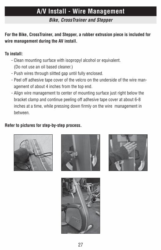
2727
For the Bike, CrossTrainer, and Stepper, a rubber extrusion piece is included for wire management during the AV install.
To install: - Clean mounting surface with isopropyl alcohol or equivalent.
(Do not use an oil based cleaner.) - Push wires through slitted gap until fully enclosed. - Peel off adhesive tape cover of the velcro on the underside of the wire man-
agement of about 4 inches from the top end. - Align wire management to center of mounting surface just right below the
bracket clamp and continue peeling off adhesive tape cover at about 6-8 inches at a time, while pressing down firmly on the wire management in between.
Refer to pictures for step-by-step process.
A/V Install - Wire ManagementBike, CrossTrainer and Stepper

800-503-1221http://support.startrac.com/
LCD Attachment Service Manual620-7581 Rev A