probes for cmms1 - · pdf fileprobes for coordinate measuring machines bulletin no. 1989...
TRANSCRIPT
Probes for Coordinate Measuring Machines
Bulletin No. 1989
Coordinate Measuring Machines
2
Ultra High-Accuracy Scanning MPP-300Q/MPP-300
Measurement rangeResolutionMax. permissible probing errorMax. permissible probing errorduring scanningSpring rateMax. stylus lengthMax. stylus massStylus mountMax. tracing speedAir flow rateProbe headApplicable modelsNo. of mountable stylus modules
±1mm0.01 mMPEPʺ0.45 m (LEGEX500/700/900: When the ø4X18mm stylus is used.)MPETHPʺ1.4 m (LEGEX500/700/900: When the ø4X18mm stylus is used.)
0.2N/mm200mm for both vertical and horizontal75gM4 screw120mm/s [at a known geometry scanning]30NL/minN/ACNC CMM (LEGEX500/700/900/1200 series)- 4 standard units [Port 1 is dedicated for the standard stylus (for calibration purpose)]- Expandable to max. 10 ports. Note, all styli should be arranged on the same axis.
MPP-300Q/MPP-300
Automaticstylus changesystem(optional)
MPP-300Q/MPP-300 Specifications
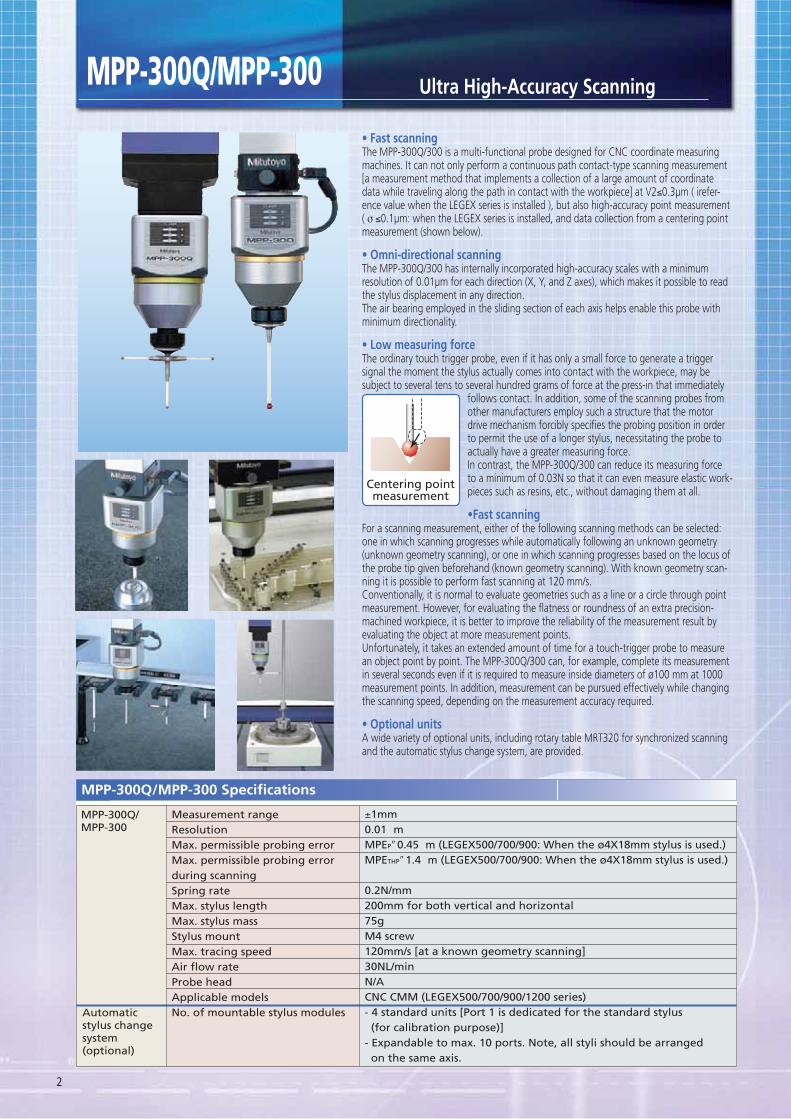
The MPP-300Q/300 is a multi-functional probe designed for CNC coordinate measuring machines. It can not only perform a continuous path contact-type scanning measurement [a measurement method that implements a collection of a large amount of coordinate data while traveling along the path in contact with the workpiece] at V2≤0.3μm ( irefer-ence value when the LEGEX series is installed ), but also high-accuracy point measurement ( σ ≤0.1μm: when the LEGEX series is installed, and data collection from a centering point measurement (shown below).
The MPP-300Q/300 has internally incorporated high-accuracy scales with a minimum resolution of 0.01μm for each direction (X, Y, and Z axes), which makes it possible to read the stylus displacement in any direction.The air bearing employed in the sliding section of each axis helps enable this probe with minimum directionality.
The ordinary touch trigger probe, even if it has only a small force to generate a trigger signal the moment the stylus actually comes into contact with the workpiece, may be subject to several tens to several hundred grams of force at the press-in that immediately
follows contact. In addition, some of the scanning probes from other manufacturers employ such a structure that the motor drive mechanism forcibly specifies the probing position in order to permit the use of a longer stylus, necessitating the probe to actually have a greater measuring force.In contrast, the MPP-300Q/300 can reduce its measuring force to a minimum of 0.03N so that it can even measure elastic work-pieces such as resins, etc., without damaging them at all.
For a scanning measurement, either of the following scanning methods can be selected: one in which scanning progresses while automatically following an unknown geometry (unknown geometry scanning), or one in which scanning progresses based on the locus of the probe tip given beforehand (known geometry scanning). With known geometry scan-ning it is possible to perform fast scanning at 120 mm/s.Conventionally, it is normal to evaluate geometries such as a line or a circle through point measurement. However, for evaluating the flatness or roundness of an extra precision-machined workpiece, it is better to improve the reliability of the measurement result by evaluating the object at more measurement points.Unfortunately, it takes an extended amount of time for a touch-trigger probe to measure an object point by point. The MPP-300Q/300 can, for example, complete its measurement in several seconds even if it is required to measure inside diameters of ø100 mm at 1000 measurement points. In addition, measurement can be pursued effectively while changing the scanning speed, depending on the measurement accuracy required.
A wide variety of optional units, including rotary table MRT320 for synchronized scanning and the automatic stylus change system, are provided.
Centering pointmeasurement
3
Detail
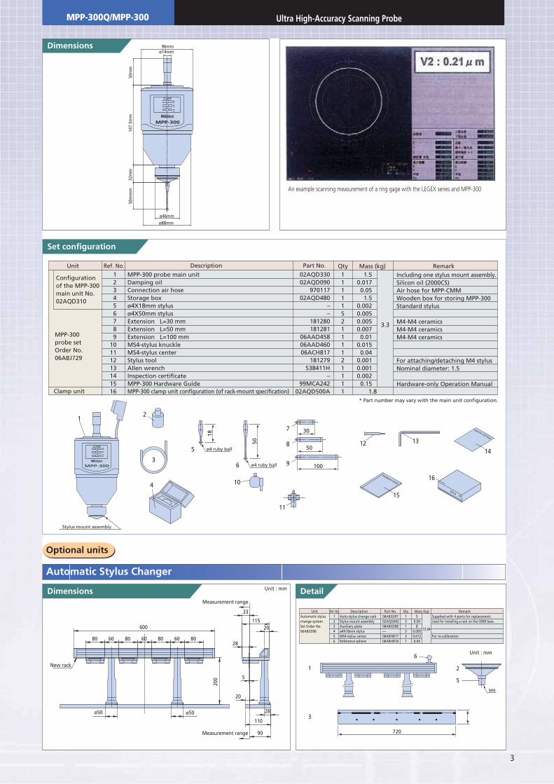
Set configuration
123456789
10111213141516
1111152111121111
1.50.017
0.051.5
0.0020.0050.0050.007
0.010.015
0.040.0010.0010.002
0.15
MPP-300 probe main unitDamping oilConnection air hoseStorage boxø4X18mm stylusø4X50mm stylusExtension L=30 mmExtension L=50 mmExtension L=100 mmMS4-stylus knuckleMS4-stylus centerStylus toolAllen wrenchInspection certificateMPP-300 Hardware GuideMPP-300 clamp unit configuration (of rack-mount specification)
02AQD33002AQD090
97011702AQD480
––
181280181281
06AAD45806AAD46006ACH817
181279538411H
–99MCA242
02AQD500A
Unit Ref. No. Description Qty Mass (kg) RemarkPart No.
Including one stylus mount assembly.Silicon oil (2000CS)Air hose for MPP-CMMWooden box for storing MPP-300Standard stylus
M4-M4 ceramicsM4-M4 ceramicsM4-M4 ceramics
For attaching/detaching M4 stylusNominal diameter: 1.5
Hardware-only Operation Manual
Configurationof the MPP-300main unit No.02AQD310
MPP-300probe setOrder No. 06ABJ729
Clamp unit 1.8
3.3
123456
Auto-stylus change rackStylus mount assemblyAuxiliary plateø4X18mm stylusMS4-stylus centerReference sphere
Automatic styluschange systemSet Order No. 06ABG596
Supplied with 4 ports for replacement.Used for installing a rack on the CMM base.
For re-calibration
06ABG59702AQD04206ABG598—06ABH81706ABH818
50.04
80.0050.0120.04
131331
13.04
Unit Ref. No. Description Part No. Mass (kg)Qty Remark
MPP-300
XYZ
CLAMP
12
3
4
6
10
7
12 13
15
14
1
3
2
5
6
16
8
9
11
Stylus mount assembly
ø4 ruby ball
50
5 ø4 ruby ball
18
30
50
100
720
M4
96mm
50m
mm
147.
5mm
32m
m50
mm
ø46mm
ø88mm
MPP-300
XYZ
CLAMP
ø14mm
New rack
Measurement range
Unit : mm
Measurement range
ø50 ø50
80608060806080
200
28
11520
28
110
5
90
600
33
20
* Part number may vary with the main unit configuration.
Hardware Guide
Inspection Certificate
Unit : mm
An example scanning measurement of a ring gage with the LEGEX series and MPP-300
MPP-300Q/MPP-300 Ultra High-Accuracy Scanning Probe
4
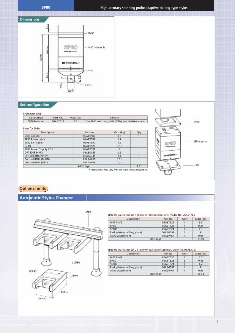
High-accuracy scanning probe adaptive to long-type stylusSP80
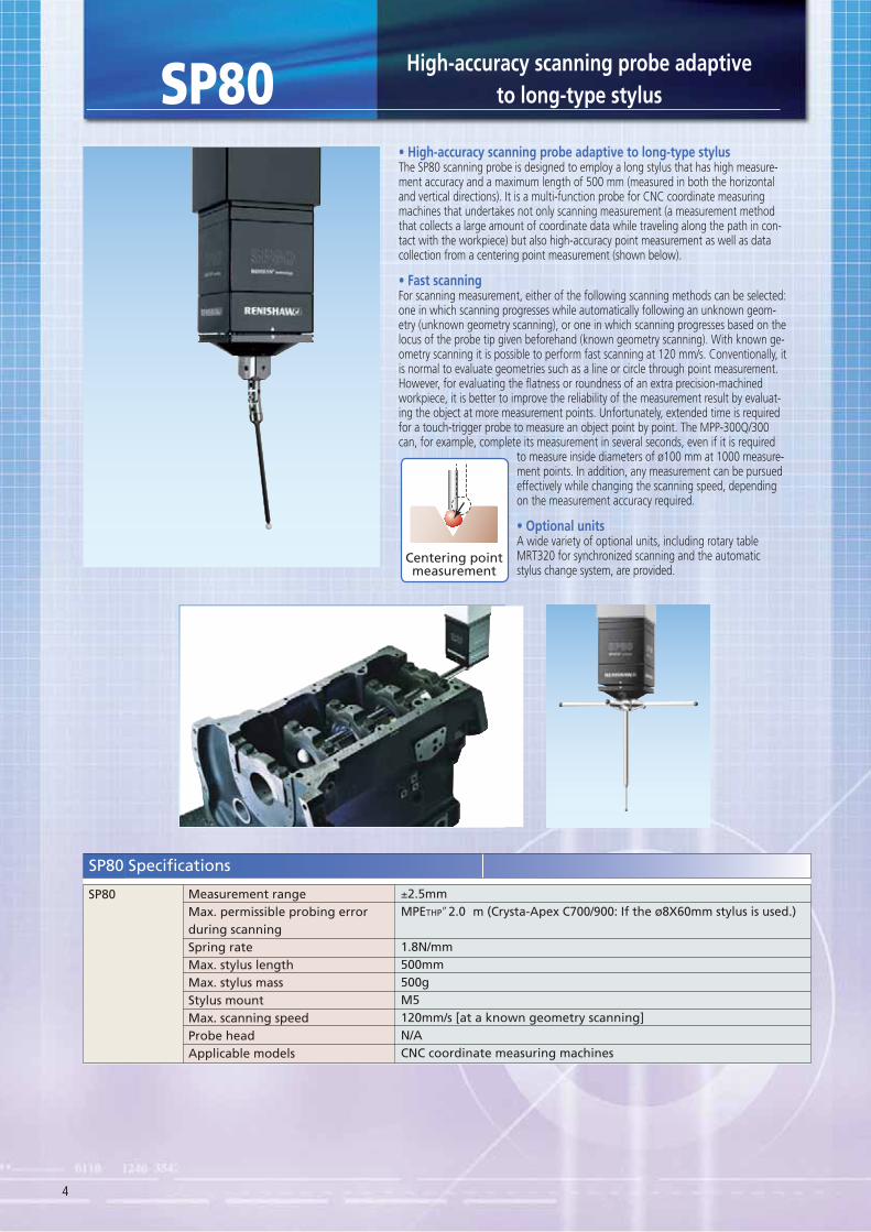
The SP80 scanning probe is designed to employ a long stylus that has high measure-ment accuracy and a maximum length of 500 mm (measured in both the horizontal and vertical directions). It is a multi-function probe for CNC coordinate measuring machines that undertakes not only scanning measurement (a measurement method that collects a large amount of coordinate data while traveling along the path in con-tact with the workpiece) but also high-accuracy point measurement as well as data collection from a centering point measurement (shown below).
For scanning measurement, either of the following scanning methods can be selected: one in which scanning progresses while automatically following an unknown geom-etry (unknown geometry scanning), or one in which scanning progresses based on the locus of the probe tip given beforehand (known geometry scanning). With known ge-ometry scanning it is possible to perform fast scanning at 120 mm/s. Conventionally, it is normal to evaluate geometries such as a line or circle through point measurement. However, for evaluating the flatness or roundness of an extra precision-machined workpiece, it is better to improve the reliability of the measurement result by evaluat-ing the object at more measurement points. Unfortunately, extended time is required for a touch-trigger probe to measure an object point by point. The MPP-300Q/300 can, for example, complete its measurement in several seconds, even if it is required
to measure inside diameters of ø100 mm at 1000 measure-ment points. In addition, any measurement can be pursued effectively while changing the scanning speed, depending on the measurement accuracy required.
A wide variety of optional units, including rotary table MRT320 for synchronized scanning and the automatic stylus change system, are provided.
Measurement rangeMax. permissible probing errorduring scanningSpring rateMax. stylus lengthMax. stylus massStylus mountMax. scanning speedProbe headApplicable models
±2.5mmMPETHPʺ2.0 m (Crysta-Apex C700/900: If the ø8X60mm stylus is used.)
1.8N/mm500mm500gM5120mm/s [at a known geometry scanning]N/ACNC coordinate measuring machines
SP80
SP80 Specifications
Centering pointmeasurement
5
Set configuration
2.606ABT513Description Mass (kg) RemarkPart No.
One SP80 main unit, SH80, KM80, and ø8X60mm stylusSP80 basic set
SP80 main unit
0.30.10.20.51
10.20.40.010.01
06ABT58706ABT58806ABT59006ABT52506ABT59106ABN86506AAS74106ZAA05806ZAA059
Description Mass (kg) QtyPart No.
111111111
3.73
SP80 adapterSP80 Probe cableSP80 EXT cableIU 80SP80 Power Supply BOXOPT200S-MPP2OPT200 attachmentControl ROM (MAIN)Control ROM (OPT)
Parts for SP80
Mass (kg)
Description Unit Mass (kg)Part No.
SP80 stylus change set 1 (600mm-rail specifications) / Oder No. 06ABT766
Mass (kg)
MRS kit#2SH80SCP80Rack plate (auxiliary plate)ACR3 attachment
06ABT52906ABT52306ABT52406ABG59806ABP467
11211
3.50.242.18
0.0513.89
Description Unit Mass (kg)Part No.
SP80 stylus change set 2 (1000mm-rail specifications) / Oder No. 06ABT767
Mass (kg)
MRS kit#3SH80SCP80Rack plate (auxiliary plate)ACR3 attachment
06ABT53006ABT52306ABT52406ABG59806ABP467
13411
3.70.484.28
0.0516.43
* Part number may vary with the main unit configuration.
6mm
106m
m
11m
m
22mm
5 x M5
SH80
SH80 main unit
KM80
21m
m
150m
m
41m
m
MRS
SCP80
SCP80
34mm
230mm
128mm
KM80
SP80 main unit
SH80
SP80 High-accuracy scanning probe adaptive to long-type stylus
6
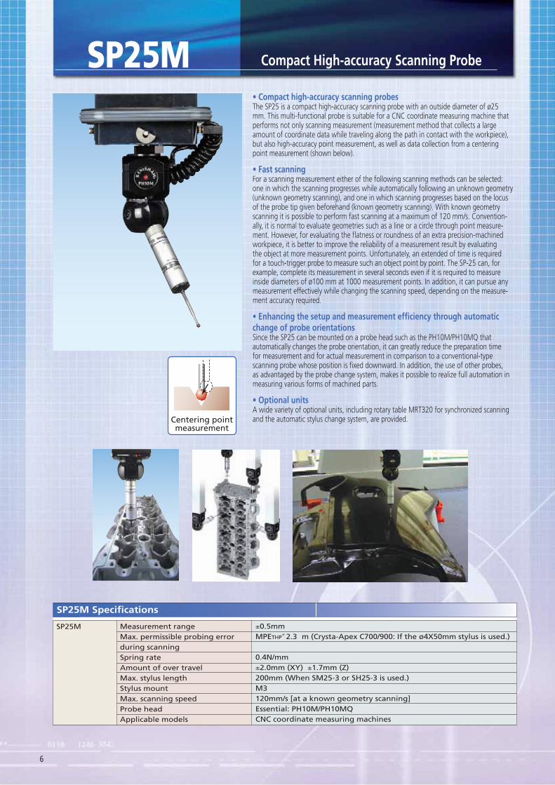
SP25MThe SP25 is a compact high-accuracy scanning probe with an outside diameter of ø25 mm. This multi-functional probe is suitable for a CNC coordinate measuring machine that performs not only scanning measurement (measurement method that collects a large amount of coordinate data while traveling along the path in contact with the workpiece), but also high-accuracy point measurement, as well as data collection from a centering point measurement (shown below).
For a scanning measurement either of the following scanning methods can be selected: one in which the scanning progresses while automatically following an unknown geometry (unknown geometry scanning), and one in which scanning progresses based on the locus of the probe tip given beforehand (known geometry scanning). With known geometry scanning it is possible to perform fast scanning at a maximum of 120 mm/s. Convention-ally, it is normal to evaluate geometries such as a line or a circle through point measure-ment. However, for evaluating the flatness or roundness of an extra precision-machined workpiece, it is better to improve the reliability of a measurement result by evaluating the object at more measurement points. Unfortunately, an extended of time is required for a touch-trigger probe to measure such an object point by point. The SP-25 can, for example, complete its measurement in several seconds even if it is required to measure inside diameters of ø100 mm at 1000 measurement points. In addition, it can pursue any measurement effectively while changing the scanning speed, depending on the measure-ment accuracy required.
change of probe orientationsSince the SP25 can be mounted on a probe head such as the PH10M/PH10MQ that automatically changes the probe orientation, it can greatly reduce the preparation time for measurement and for actual measurement in comparison to a conventional-type scanning probe whose position is fixed downward. In addition, the use of other probes, as advantaged by the probe change system, makes it possible to realize full automation in measuring various forms of machined parts.
A wide variety of optional units, including rotary table MRT320 for synchronized scanning and the automatic stylus change system, are provided.
Measurement rangeMax. permissible probing errorduring scanningSpring rateAmount of over travelMax. stylus lengthStylus mountMax. scanning speedProbe headApplicable models
±0.5mmMPETHPʺ2.3 m (Crysta-Apex C700/900: If the ø4X50mm stylus is used.)
0.4N/mm±2.0mm (XY) ±1.7mm (Z)200mm (When SM25-3 or SH25-3 is used.)M3120mm/s [at a known geometry scanning]Essential: PH10M/PH10MQCNC coordinate measuring machines
SP25M
SP25M Specifications
Centering pointmeasurement
7
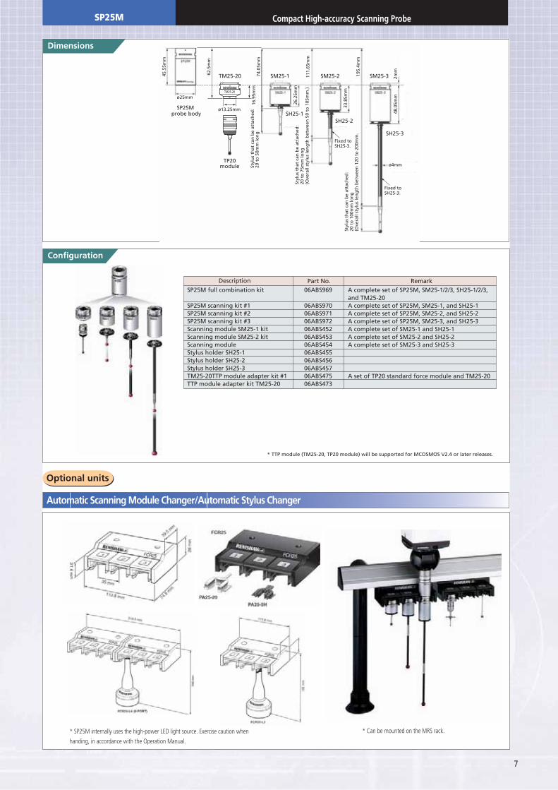
Configuration
A complete set of SP25M, SM25-1/2/3, SH25-1/2/3,and TM25-20A complete set of SP25M, SM25-1, and SH25-1A complete set of SP25M, SM25-2, and SH25-2A complete set of SP25M, SM25-3, and SH25-3A complete set of SM25-1 and SH25-1A complete set of SM25-2 and SH25-2A complete set of SM25-3 and SH25-3
A set of TP20 standard force module and TM25-20
06ABS969
06ABS97006ABS97106ABS97206ABS45206ABS45306ABS45406ABS45506ABS45606ABS45706ABS47506ABS473
Description RemarkPart No.SP25M full combination kit
SP25M scanning kit #1SP25M scanning kit #2SP25M scanning kit #3Scanning module SM25-1 kitScanning module SM25-2 kitScanning moduleStylus holder SH25-1Stylus holder SH25-2Stylus holder SH25-3TM25-20TTP module adapter kit #1TTP module adapter kit TM25-20
* TTP module (TM25-20, TP20 module) will be supported for MCOSMOS V2.4 or later releases.
TM25-20
45.5
5mm
62.5
mm
74.0
5mm
16.9
5mm
111.
65m
m
195.
4mm
48.0
5mm
33.8
5mm
26.2
5mm
2mm
SH25-3
SM25-3SM25-2SM25-1TM25-20
SH25-2SH25-1
TP20module
SP25M probe body
ø13.25mm
ø25mm
Styl
us
that
can
be
atta
ched
:20
to
50m
m lo
ng
Styl
us
that
can
be
atta
ched
:20
to
75m
m lo
ng
(Ove
rall
styl
us
len
gth
bet
wee
n 5
0 to
105
mm
.)
Styl
us
that
can
be
atta
ched
:20
to
100
mm
lon
g(O
vera
ll st
ylu
s le
ng
th b
etw
een
120
to
200
mm
.
ø4mm
Fixed toSH25-3.
Fixed toSH25-3.
SP25M
* Can be mounted on the MRS rack.* SP25M internally uses the high-power LED light source. Exercise caution when
handing, in accordance with the Operation Manual.
8
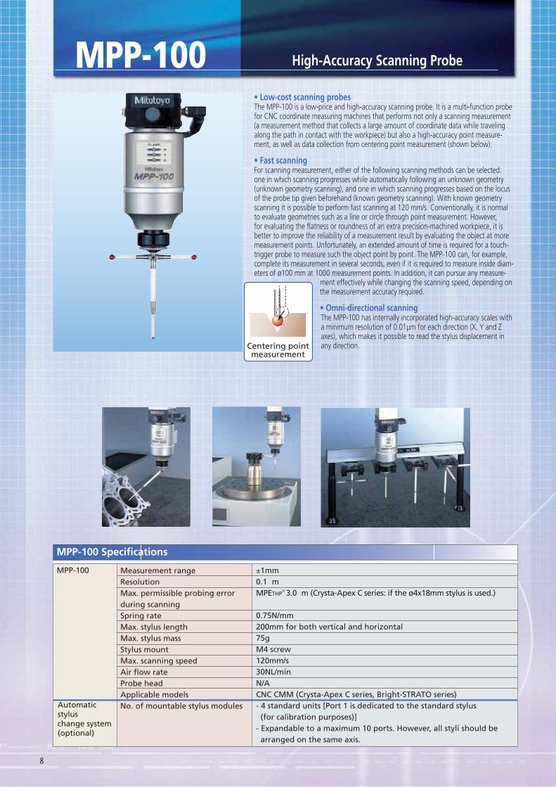
High-Accuracy Scanning Probe
Measurement rangeResolutionMax. permissible probing errorduring scanningSpring rateMax. stylus lengthMax. stylus massStylus mountMax. scanning speedAir flow rateProbe headApplicable modelsNo. of mountable stylus modules
±1mm0.1 mMPETHPʺ3.0 m (Crysta-Apex C series: if the ø4x18mm stylus is used.)
0.75N/mm200mm for both vertical and horizontal75gM4 screw120mm/s30NL/minN/ACNC CMM (Crysta-Apex C series, Bright-STRATO series)- 4 standard units [Port 1 is dedicated to the standard stylus (for calibration purposes)]- Expandable to a maximum 10 ports. However, all styli should be arranged on the same axis.
MPP-100
Automaticstyluschange system(optional)
MPP-100 Specifications
MPP-100
Centering pointmeasurement
The MPP-100 is a low-price and high-accuracy scanning probe. It is a multi-function probe for CNC coordinate measuring machines that performs not only a scanning measurement (a measurement method that collects a large amount of coordinate data while traveling along the path in contact with the workpiece) but also a high-accuracy point measure-ment, as well as data collection from centering point measurement (shown below).
For scanning measurement, either of the following scanning methods can be selected: one in which scanning progresses while automatically following an unknown geometry (unknown geometry scanning), and one in which scanning progresses based on the locus of the probe tip given beforehand (known geometry scanning). With known geometry scanning it is possible to perform fast scanning at 120 mm/s. Conventionally, it is normal to evaluate geometries such as a line or circle through point measurement. However, for evaluating the flatness or roundness of an extra precision-machined workpiece, it is better to improve the reliability of a measurement result by evaluating the object at more measurement points. Unfortunately, an extended amount of time is required for a touch-trigger probe to measure such the object point by point. The MPP-100 can, for example, complete its measurement in several seconds, even if it is required to measure inside diam-eters of ø100 mm at 1000 measurement points. In addition, it can pursue any measure-
ment effectively while changing the scanning speed, depending on the measurement accuracy required.
The MPP-100 has internally incorporated high-accuracy scales with a minimum resolution of 0.01μm for each direction (X, Y and Z axes), which makes it possible to read the stylus displacement in any direction.
9
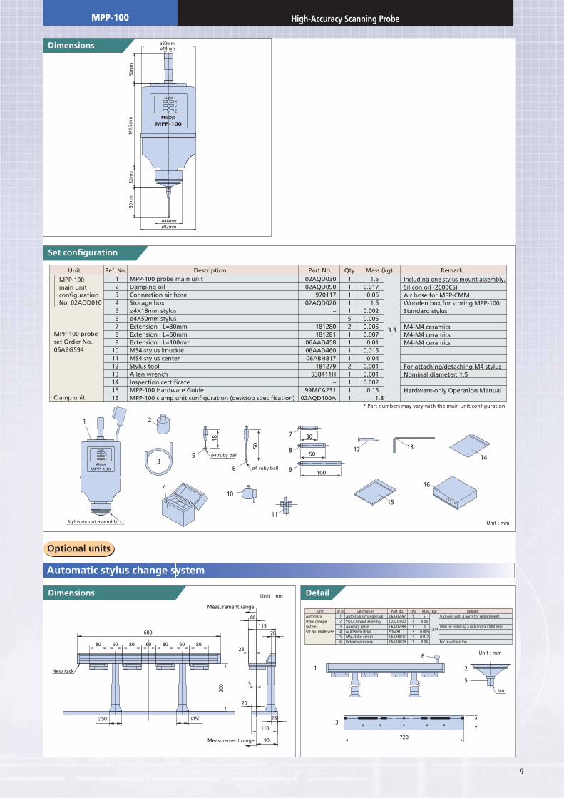
Set configuration
ø92mmø46mm
ø90mmø14mm
50m
m14
1.5m
m32
mm
50m
mMPP-100
XYZ
CLAMP
123456789
10111213141516
1111152111121111
1.50.017
0.051.5
0.0020.0050.0050.007
0.010.015
0.040.0010.0010.002
0.15
MPP-100 probe main unitDamping oilConnection air hoseStorage boxø4X18mm stylusø4X50mm stylusExtension L=30mmExtension L=50mmExtension L=100mmMS4-stylus knuckleMS4-stylus centerStylus toolAllen wrenchInspection certificateMPP-100 Hardware GuideMPP-100 clamp unit configuration (desktop specification)
02AQD03002AQD090
97011702AQD020
––
181280181281
06AAD45806AAD46006ABH817
181279538411H
–99MCA231
02AQD100A
Unit Ref. No. Description Qty Mass (kg) RemarkPart No.Including one stylus mount assembly.Silicon oil (2000CS)Air hose for MPP-CMMWooden box for storing MPP-100Standard stylus
M4-M4 ceramicsM4-M4 ceramicsM4-M4 ceramics
For attaching/detaching M4 stylusNominal diameter: 1.5
Hardware-only Operation Manual
MPP-100main unitconfigurationNo. 02AQD010
MPP-100 probeset Order No.06ABG594
Clamp unit 1.8
3.3
2
3
4
6
10
7
12 13
15
14
16
8
9
11
ø4 ruby ball
50
30
50
100
5 ø4 ruby ball
18
Detail
123456
Auto-stylus change rackStylus mount assemblyAuxiliary plateø4X18mm stylusMS4-stylus centerReference sphere
Automaticstylus changesystemSet No. 06ABG596
Supplied with 4 ports for replacement.
Used for installing a rack on the CMM base.
For re-calibration
06ABG59702AQD04206ABG59891649106ABH81706ABH818
50.04
80.0050.0120.04
131331
13.04
Unit Ref. No. Description Part No. Mass (kg)Qty Remark
1
3
2
5
6
720
M4
New rack
Measurement range
Measurement range
Ø50 Ø50
80608060806080
200
28
11520
28
110
5
90
600
33
20
* Part numbers may vary with the main unit configuration.
MPP-100
XYZ
CLAMP
1
Stylus mount assembly
Unit : mm
Hardware Guide
Inspection Certificate
Unit : mm
Unit : mm
MPP-100 High-Accuracy Scanning Probe
10
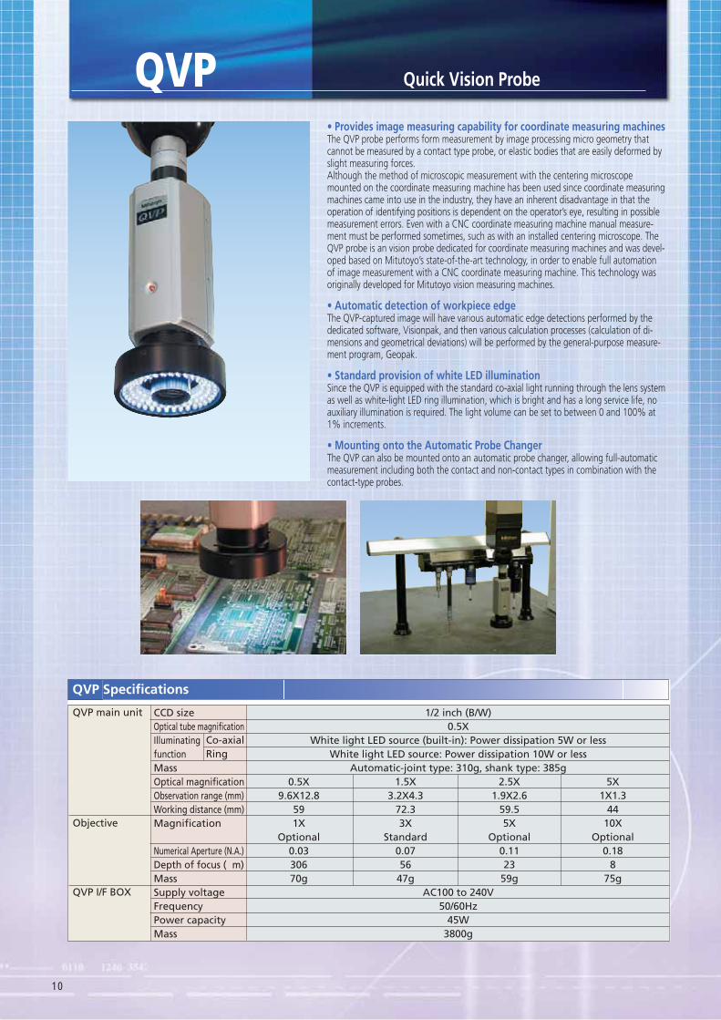
The QVP probe performs form measurement by image processing micro geometry that cannot be measured by a contact type probe, or elastic bodies that are easily deformed by slight measuring forces.Although the method of microscopic measurement with the centering microscope mounted on the coordinate measuring machine has been used since coordinate measuring machines came into use in the industry, they have an inherent disadvantage in that the operation of identifying positions is dependent on the operator’s eye, resulting in possible measurement errors. Even with a CNC coordinate measuring machine manual measure-ment must be performed sometimes, such as with an installed centering microscope. The QVP probe is an vision probe dedicated for coordinate measuring machines and was devel-oped based on Mitutoyo’s state-of-the-art technology, in order to enable full automation of image measurement with a CNC coordinate measuring machine. This technology was originally developed for Mitutoyo vision measuring machines.
The QVP-captured image will have various automatic edge detections performed by the dedicated software, Visionpak, and then various calculation processes (calculation of di-mensions and geometrical deviations) will be performed by the general-purpose measure-ment program, Geopak.
Since the QVP is equipped with the standard co-axial light running through the lens system as well as white-light LED ring illumination, which is bright and has a long service life, no auxiliary illumination is required. The light volume can be set to between 0 and 100% at 1% increments.
The QVP can also be mounted onto an automatic probe changer, allowing full-automatic measurement including both the contact and non-contact types in combination with the contact-type probes.
CCD sizeOptical tube magnificationIlluminatingfunctionMassOptical magnificationObservation range (mm)Working distance (mm)Magnification
Numerical Aperture (N.A.)Depth of focus ( m)MassSupply voltageFrequencyPower capacityMass
QVP main unit
Objective
QVP I/F BOX
Co-axialRing
1/2 inch (B/W)0.5X
White light LED source (built-in): Power dissipation 5W or lessWhite light LED source: Power dissipation 10W or less
Automatic-joint type: 310g, shank type: 385g
AC100 to 240V50/60Hz
45W3800g
0.5X9.6X12.8
591X
Optional0.0330670g
1.5X3.2X4.3
72.33X
Standard0.0756
47g
2.5X1.9X2.6
59.55X
Optional0.1123
59g
5X1X1.3
4410X
Optional0.18
875g
QVP
11
Data processing unit
ocessing Tool
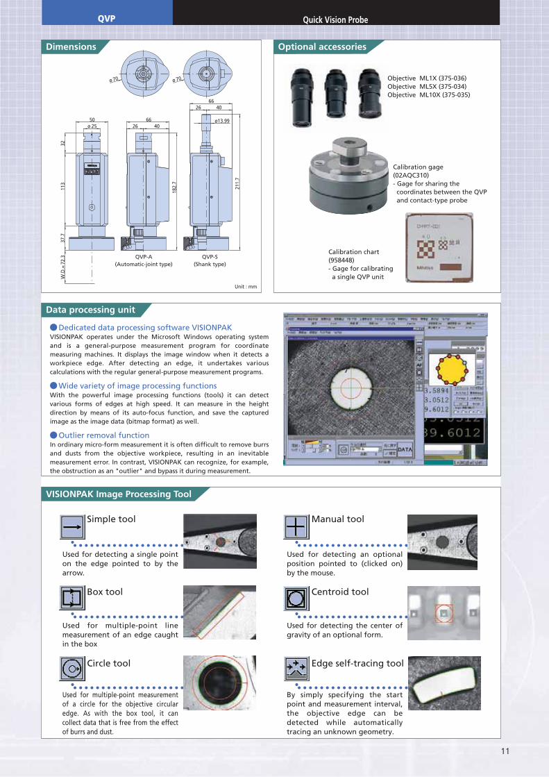
Dedicated data processing software VISIONPAK VISIONPAK operates under the Microsoft Windows operating system and is a general-purpose measurement program for coordinate measuring machines. It displays the image window when it detects a workpiece edge. After detecting an edge, it undertakes various calculations with the regular general-purpose measurement programs.
Wide variety of image processing functionsWith the powerful image processing functions (tools) it can detect various forms of edges at high speed. It can measure in the height direction by means of its auto-focus function, and save the captured image as the image data (bitmap format) as well.
Outlier removal functionIn ordinary micro-form measurement it is often difficult to remove burrs and dusts from the objective workpiece, resulting in an inevitable measurement error. In contrast, VISIONPAK can recognize, for example, the obstruction as an "outlier" and bypass it during measurement.
ø 70 ø 70
211.
7
182.
7
50ø 25
3211
337
.7W
.D.=
72.3
26 4066
26 4066
ø13.99
Used for multiple-point measurement of a circle for the objective circular edge. As with the box tool, it can collect data that is free from the effect of burrs and dust.
Used for detecting a single point on the edge pointed to by the arrow.
Used for multiple-point line measurement of an edge caught in the box
Circle tool
Box tool
Simple tool
By simply specifying the start point and measurement interval, the objective edge can be detected while automatically tracing an unknown geometry.
Used for detecting an optional position pointed to (clicked on) by the mouse.
Used for detecting the center of gravity of an optional form.
Edge self-tracing tool
Centroid tool
Manual tool
QVP-A(Automatic-joint type)
QVP-S(Shank type)
Objective ML1X (375-036)Objective ML5X (375-034)Objective ML10X (375-035)
Calibration gage(02AQC310)- Gage for sharing the coordinates between the QVP and contact-type probe
Calibration chart(958448)- Gage for calibrating a single QVP unit
Unit : mm
QVP

12
The CF20 is a centering microscope that enables measurement of small holes and elastic bodies which are difficult for a touch trigger probe to measure. With the CF20 the coordi-nate measuring machine can be used as a large microscope.
To cope with the size and form of a workpiece to be observed and measured, lenses of various magnifications and reticles for form comparison are provided.
The dedicated CCD camera can be mounted on the back of the CF20 main unit. Video signals from the camera can be displayed as an image on the external monitor. This is a great aid in relieving eye stress, especially if several hours of work must be done.
Centering Microscope for Coordinate Measuring MachinesCF20
Eyepiece
Objective(optional)
CF20 main unit
211mm
Illumination unit
Monocular unit
51m
m
22.5
mm
117m
m50
mm
30˚
ø14mm
CF20 monocular set (375-201) CF20 binocular set (375-202) CF20 disc plate set (375-205)
Illumination unit (375-071) Specification
CF10X eyepiece, field number 22Cross hair and concentric circle reticle
CF10X eyepiece, field number 22Cross hair and concentric circle reticle (right)Pupil distance adjustment: 51 - 76mm
CF10X eyepiece, field number 21Measurement range: 360˚, Angle index: 1˚Minimum reading: 5' (vernier scale)
CF10X eyepiece, field number 22
CF10X eyepiece, field number 22ISO metric/unify screwsCross hair and concentric circle reticle/dotted line cross scale, ML 3X objective
CF20 monocularset (375-201)
CF20 binocularset (375-202)
CF20 protractoreyepiece set
(375-203)
CF20 doubleimage set (375-204)
CF20 disc plateset (375-205)
Description
1. Illumination unit (375-071)
2. Spare lamp (162151)
3. Lens cap
4. Tools
5. Power cable
6. Operation Manual
7. Storage box
Accessory
Specifications
CF20 protractor eyepiece set (375-203)
Monocular unit
Shank (ø14mm)
Main unit
Binocular unit
Shank (ø14mm)
Main unit
Protractor eyepiece unit
Shank (ø14mm)
Main unit
Double-image eyepiece unit
Shank (ø14mm)
Main unit
Disc-plate eyepiece unitShank (ø14mm)
Lamp-house
Powersupply box
Main unit
CF20 double image set(375-204)
13
der No. 320-053]
(cross hair andconcentric circle)
(90º/60º dash-dot line)
No. 375-021 No. 375-022 No. 375-023 No. 375-024
ø18 60º
0.21
10
10
1
0.2
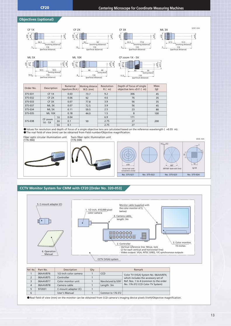
CF 1X CF 2X CF 3X
36.3 73.7(working distance)
110(parfocal distance)
5
ø30
ø25
ø26
18 92(working distance)
110(parfocal distance)
12
ø30
ø25
ø22
32.2 77.8(working distance)
110(parfocal distance)
5
ø30
ø25
ML 3X
37.5 72.5(working distance)
110(parfocal distance)
5
ø30
ø25
ML 5X
50.5 59.5(working distance)
110(parfocal distance)
10.5
ø30
ø28
ø25
ø17
ML 10X
66 44(working distance)
110(parfocal distance)
8
ø30
ø28
ø25
ø21
.2
CF zoom 1X - 5X
60 50(working distance)
110(parfocal distance)
11.5
ø34
ø25
ø21
.5
ø37
.2
Order No.
375-031
375-032
375-033
375-037
375-034
375-035
375-038
Ref. No.
1
2
3
4
5
6
Part No.
06AAV876
06AAV875
06AAV877
06AAV878
972031
Description
1/2-inch color camera
Controller
Color monitor unit
Camera cable
C-mount adapter (C)
User's Manual
Qty
1
1
1
1
1
1
Remark
CCD
Manufactured by SONY
Length: 3m
Common to 176-372
Color TV (VGA) System No. 06AAV874,which includes the accessory set ofRef. Nos. 1 to 4 (common to the orderNo. 176-372 CCD Color TV System)
Description
CF 1X
CF 2X
CF 3X
ML 3X
ML 5X
ML 10X
0.03
0.06
0.07
0.07
0.11
0.18
0.04
0.1
0.1
NumericalAperture (N.A.)
Working distanceW.D. (mm)
ResolutionR ( m)
306
76
56
56
23
8
171
27
27
CF zoom1X - 5X
1X
3X
5X
Depth of focus of singleobjective lens ±D.F. ( m)
Mass(g)
73.7
92
77.8
72.5
59.5
44.0
50
9.2
4.6
3.9
3.9
2.5
1.5
6.9
2.75
2.75
45
35
35
45
80
100
200
Values for resolution and depth of focus of a single objective lens are calculated based on the reference wavelength ( =0.55 m). The real field of view (mm) can be obtained from Field number/Objective magnification.
Real field of view (mm) on the monitor can be obtained from CCD camera's imaging device pixels (VxH)/Objective magnification.
Fiber optic circular illumination unit(176-366)
Twin-fiber optic illumination unit(176-344)
5. C-mount adapter (C)
6. Operation Manual
1. 1/2-inch, 410,000-pixel color camera
4. Camera cable,
Monitor cable (supplied withthe color monitor of 3,below)
length: 3m
2. Controller
CCTV (VGA) system
3. Color monitor,15-inches- Vertical reference line: Move, lock
(2 for each vertical and horizontal line)- Video output: VGA, NTSC (VBS), Y/C synchronous outputs
Unit: mm
Unit: mm
(grid)
CF20 Centering Microscope for Coordinate Measuring Machines
14
Measuring directionStandard stylusRepeatability (2 )Directionality (XY: 2D)Required force to generatetrigger signalAmount of over-travel
Required force to achieveover-travelMaximum stylus lengthStylus mounting methodMass of a single unitDurabilityProbe headApplicable models
XYZXYZXYZ
±X, ±Y, +Zø4X18mm0.25 m or less (When the standard stylus is used.)±0.25 m or less0.02N (When the 50mm stylus is used.)0.15N (When the 50mm stylus is used.)±16º±5mm0.49N (When the 50mm stylus is used.)2.94N (When the 50mm stylus is used.)150mmM4 screw85g10,000,000 timesEssential: PH10M/PH10MQCNC coordinate measuring machines
TP7M
TP7M Specifications
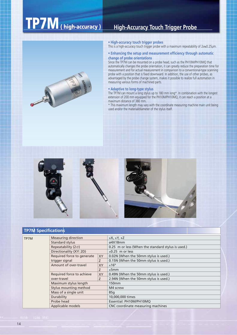
TP7M ( high-accuracy ) High-Accuracy Touch Trigger Probe
This is a high-accuracy touch trigger probe with a maximum repeatability of 2σ≤0.25μm.
change of probe orientationsSince the TP7M can be mounted on a probe head, such as the PH10M/PH10MQ that automatically changes the probe orientation, it can greatly reduce the preparation time for measurement and for actual measurement in comparison to a conventional-type scanning probe with a position that is fixed downward. In addition, the use of other probes, as advantaged by the probe change system, makes it possible to realize full automation in measuring various forms of machined parts.
The TP7M can mount a long stylus up to 180 mm long*. In combination with the longest extension of 200 mm equipped for the PH10M/PH10MQ, it can reach a position at a maximum distance of 380 mm.* This maximum length may vary with the coordinate measuring machine main unit being used and/or the material/diameter of the stylus itself.
15
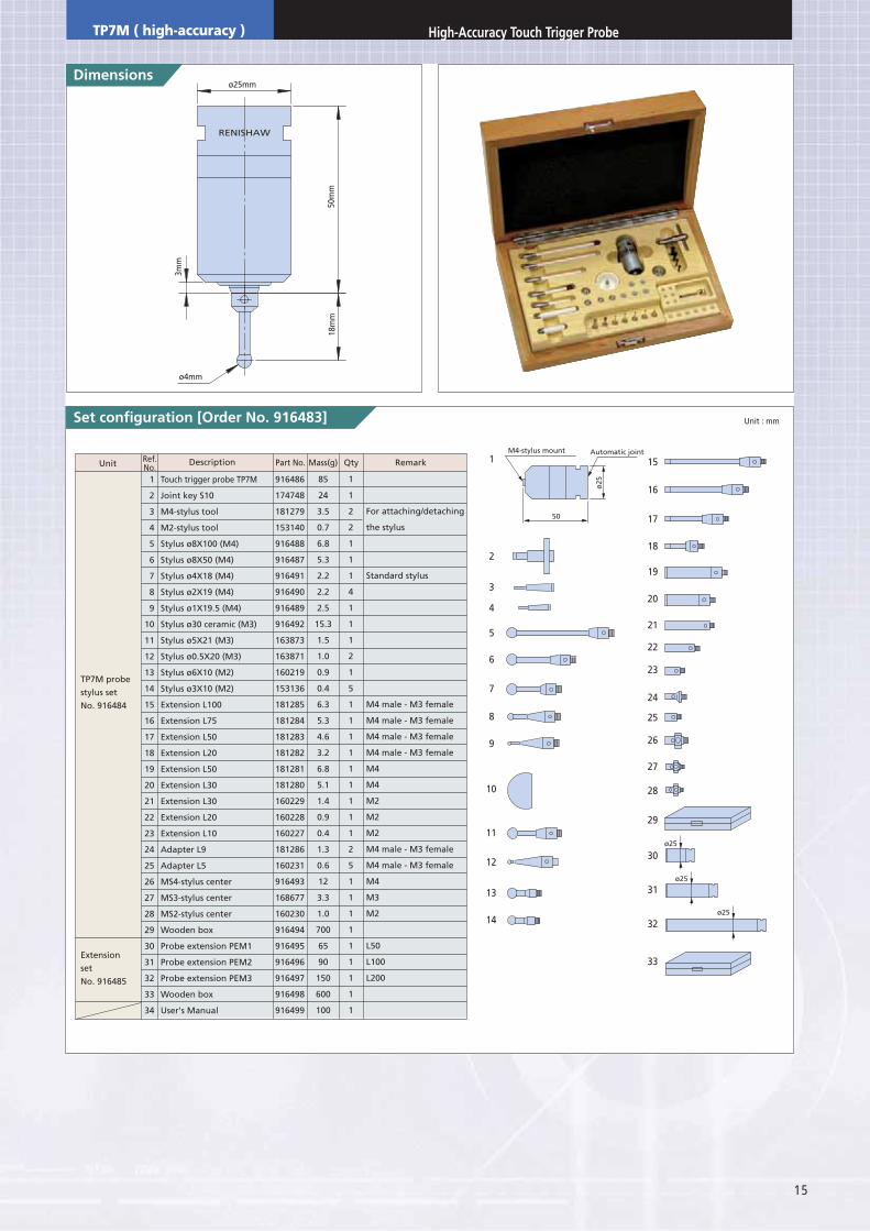
der No. 916483]
RENISHAW
ø4mm
ø25mm
50m
m
3mm
18m
m
1
2
3
4
5
6
7
8
9
10
11
12
13
14
15
16
17
18
19
20
21
22
23
24
25
26
27
28
29
30
31
32
33
34
Touch trigger probe TP7M
Joint key S10
M4-stylus tool
M2-stylus tool
Stylus ø8X100 (M4)
Stylus ø8X50 (M4)
Stylus ø4X18 (M4)
Stylus ø2X19 (M4)
Stylus ø1X19.5 (M4)
Stylus ø30 ceramic (M3)
Stylus ø5X21 (M3)
Stylus ø0.5X20 (M3)
Stylus ø6X10 (M2)
Stylus ø3X10 (M2)
Extension L100
Extension L75
Extension L50
Extension L20
Extension L50
Extension L30
Extension L30
Extension L20
Extension L10
Adapter L9
Adapter L5
MS4-stylus center
MS3-stylus center
MS2-stylus center
Wooden box
Probe extension PEM1
Probe extension PEM2
Probe extension PEM3
Wooden box
User's Manual
916486
174748
181279
153140
916488
916487
916491
916490
916489
916492
163873
163871
160219
153136
181285
181284
181283
181282
181281
181280
160229
160228
160227
181286
160231
916493
168677
160230
916494
916495
916496
916497
916498
916499
85
24
3.5
0.7
6.8
5.3
2.2
2.2
2.5
15.3
1.5
1.0
0.9
0.4
6.3
5.3
4.6
3.2
6.8
5.1
1.4
0.9
0.4
1.3
0.6
12
3.3
1.0
700
65
90
150
600
100
1
1
2
2
1
1
1
4
1
1
1
2
1
5
1
1
1
1
1
1
1
1
1
2
5
1
1
1
1
1
1
1
1
1
For attaching/detaching
the stylus
Standard stylus
M4 male - M3 female
M4 male - M3 female
M4 male - M3 female
M4 male - M3 female
M4
M4
M2
M2
M2
M4 male - M3 female
M4 male - M3 female
M4
M3
M2
L50
L100
L200
TP7M probe
stylus set
No. 916484
Extension
set
No. 916485
Unit Part No.Description RemarkMass(g) QtyRef.No.
1 15
16
17
18
19
20
21
22
23
24
25
26
27
28
29
30
31
32
33
2
3
4
5
6
7
8
9
10
11
12
13
14
M4-stylus mount
50
ø25
ø25
ø25
ø25
Automatic joint
Unit : mm
TP7M ( high-accuracy ) High-Accuracy Touch Trigger Probe
16
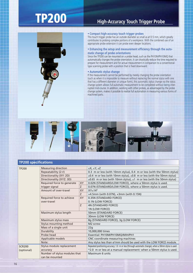
This touch trigger probe has an outside diameter as small as ø13.5 mm, which greatly contributes to probing complex portions of a workpiece. With the combined use of an appropriate probe extension it can probe even deeper locations.
-
Since the TP200 can be mounted on a probe head, such as the PH10M/PH10MQ that automatically changes the probe orientation, it can drastically reduce the time required to prepare for measurement and for actual measurement in comparison to a conventional-type scanning probe with a position that is fixed downward.
If the measurement cannot be performed by merely changing the probe orientation (such as when it is impossible to measure without replacing the normal stylus with one that has a different diameter or unique form), this automatic stylus change via the stylus change system allows full-automatic measurement to be completed without being inter-rupted mid-course. In addition, working with other probes, as advantaged by the probe change system, makes it possible to realize full automation in measuring various forms of machined parts.
High-Accuracy Touch Trigger ProbeTP200
Measuring directionRepeatability (2 )Directionality (XY: 2D)Directionality (XYZ: 3D)Required force to generatetrigger signalAmount of over-travel
Required force to achieveover-travel
Maximum stylus length
Maximum stylus massStylus mounting methodMass of a single unitDurabilityProbe headApplicable modelsNote:Stylus module replacementaccuracyNumber of stylus modules thatcan be mounted
XYZXYZXY
Z
±X, ±Y, ±Z0.3 m or less (with 10mm stylus), 0.4 m or less (with the 50mm stylus)±0.4 m or less (with 10mm stylus), ±0.8 m or less (with the 50mm stylus)±0.65 m or less (with 10mm stylus), ±1 m or less (with the 50mm stylus)0.02N (STANDARD/LOW FORCE), where a 50mm stylus is used.0.07N (STANDARD/LOW FORCE), where a 50mm stylus is used.XY±14º+4.5mm (with 0.07N), +3mm (with 0.15N)0.35N (STANDARD FORCE)0.1N (LOW FORCE)4N (STANDARD FORCE)1N (LOW FORCE)50mm (STANDARD FORCE)30mm (LOW FORCE)8g (STANDARD FORCE), 3g (LOW FORCE)M2 screw22g10,000,000 timesEssential: PH10M/PH10MQ/MIH/PH1CNC coordinate measuring machinesAny stylus less than ø1mm should be used with the LOW FORCE module.Repeated positioning accuracy: 1.0 m or less (through automatic change), when a 50mm stylus is used.*2.0 m or less at a manual replacement: when a 50mm stylus is used.Maximum 6 units
SCR200(optional)
TP200
TP200 specifications
17
Stylus module
Probe main unit
M2X0.4
M8
ø4mm
RENISHAW
TP200
10m
m13
mm
30m
m
ø13.5mm
123456789
101112131415
111111111111111
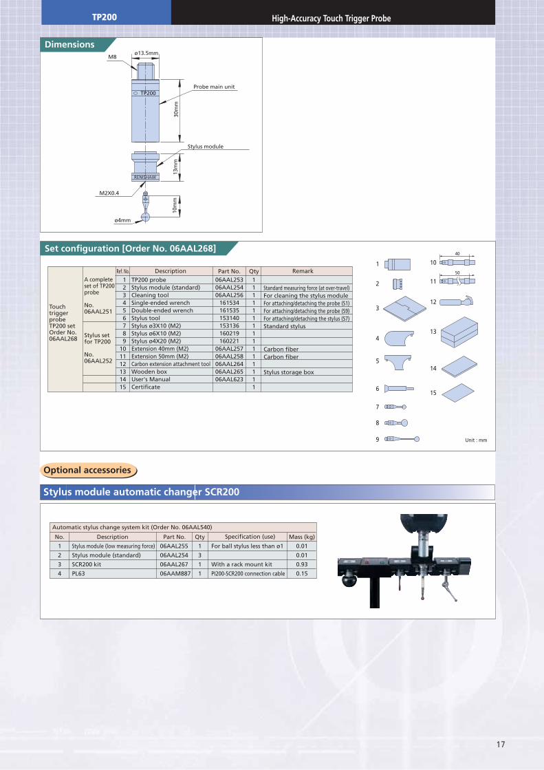
TP200 probeStylus module (standard)Cleaning toolSingle-ended wrenchDouble-ended wrenchStylus toolStylus ø3X10 (M2)Stylus ø6X10 (M2)Stylus ø4X20 (M2)Extension 40mm (M2)Extension 50mm (M2)Carbon extension attachment toolWooden boxUser's ManualCertificate
Ref. No. Description Qty RemarkPart No.
Standard measuring force (at over-travel)For cleaning the stylus moduleFor attaching/detaching the probe (S1)For attaching/detaching the probe (S9)For attaching/detaching the stylus (S7)Standard stylus
Carbon fiberCarbon fiber
Stylus storage box
TouchtriggerprobeTP200 setOrder No.06AAL268
A completeset of TP200probe
No.06AAL251
Stylus setfor TP200
No.06AAL252
06AAL25306AAL25406AAL256
161534161535153140153136160219160221
06AAL25706AAL25806AAL26406AAL26506AAL623
1
2
3
4
5
6
7
8
9
10
11
12
13
14
15
40
50
No.
1
2
3
4
Description
Stylus module (low measuring force)
Stylus module (standard)
SCR200 kit
PL63
Part No.
06AAL255
06AAL254
06AAL267
06AAM887
Qty
1
3
1
1
Mass (kg)
0.01
0.01
0.93
0.15
Specification (use)
Automatic stylus change system kit (Order No. 06AAL540)
For ball stylus less than ø1
With a rack mount kit
PI200-SCR200 connection cable
Unit : mm
TP200 High-Accuracy Touch Trigger Probe
18
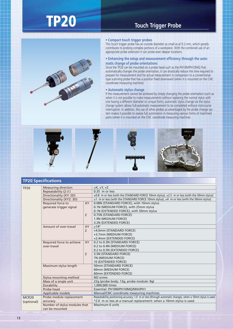
This touch trigger probe has an outside diameter as small as ø13.2 mm, which greatly contributes to probing complex portions of a workpiece. With the combined use of an appropriate probe extension it can probe even deeper locations.
-
Since the TP20 can be mounted on a probe head such as the PH10M/PH10MQ that automatically changes the probe orientation, it can drastically reduce the time required to prepare for measurement and for actual measurement in comparison to a conventional-type scanning probe that has a position fixed downward (when it is mounted on the CNC coordinate measuring machine).
If the measurement cannot be achieved by simply changing the probe orientation (such as when it is not possible to make measurements without replacing the normal stylus with one having a different diameter or unique form), automatic stylus change via the stylus change system allows full-automatic measurement to be completed without mid-course interruption. In addition, the use of other probes as advantaged by the probe change sys-tem makes it possible to realize full automation in measuring various forms of machined parts (when it is mounted on the CNC coordinate measuring machine).
Touch Trigger Probe
Measuring directionRepeatability (2 )Directionality (XY: 2D)Directionality (XYZ: 3D)Required force togenerate trigger signal
Amount of over-travel
Required force to achieveover-travel
Maximum stylus length
Stylus mounting methodMass of a single unitDurabilityProbe headApplicable modelsProbe module replacementaccuracyNumber of stylus modules thatcan be mounted
XY
Z
XYZ
XY
Z
±X, ±Y, +Z0.35 m or less±0.8 m or less (with the STANDARD FORCE 10mm stylus), ±2.5 m or less (with the 50mm stylus)±1 m or less (with the STANDARD FORCE 10mm stylus), ±4 m or less (with the 50mm stylus)0.08N (STANDARD FORCE), with 10mm stylus0.1N (MEDIUM FORCE), with 25mm stylus0.1N (EXTENDED FORCE), with 50mm stylus0.75N (STANDARD FORCE)1.9N (MEDIUM FORCE)3.2N (EXTENDED FORCE)±14º+4.0mm (STANDARD FORCE)+3.7mm (MEDIUM FORCE)+2.4mm (EXTENDED FORCE)0.2 to 0.3N (STANDARD FORCE)0.2 to 0.4N (MEDIUM FORCE)0.2 to 0.5N (EXTENDED FORCE)3.5N (STANDARD FORCE)7N (MEDIUM FORCE)10 (EXTENDED FORCE)50mm (STANDARD FORCE)60mm (MEDIUM FORCE)60mm (EXTENDED FORCE)M2 screw22g (probe body: 13g, probe module: 9g)1,000,000 timesEssential: PH10M/PH10MQ/MIH/PH1Manual/CNC coordinate measuring machinesRepeatability positioning accuracy: 1.0 m or less (through automatic change), when a 10mm stylus is used.*2.0 m or less at a manual replacement: when a 10mm stylus is used.Maximum 6 units
TP20
MCR20(optional)
TP20 Specifications
TP20
19
der No. 06AA
123456789
10
1111112111
13g9g9g
0.4g54g5g5g1g
100g1g
450g
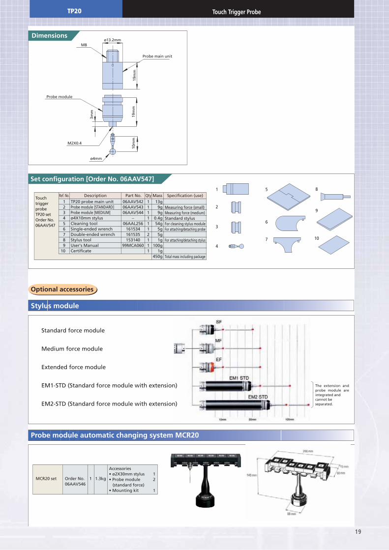
TP20 probe main unitProbe module [STANDARD]Probe module [MEDIUM]ø4X10mm stylusCleaning toolSingle-ended wrenchDouble-ended wrenchStylus toolUser's ManualCertificate
Accessories12
(standard force)1
06AAV54206AAV54306AAV544
–06AAL256
161534161535153140
99MCA060
Ref. No. Description Qty Mass Specification (use)Part No.
Measuring force (small)Measuring force (medium)Standard stylusFor cleaning stylus moduleFor attaching/detaching probe
For attaching/detaching stylus
Total mass including package
TouchtriggerprobeTP20 setOrder No.06AAV547
MCR20 set Order No.06AAV546
1.3kg1
1
2
3
4
6
5
10
9
8
7
M2X0.4
ø4mm
Probe module
Probe main unit
M8
19m
m
3mm
10m
m19
mm
ø13.2mm
Pr
Standard force module
Medium force module
Extended force module
EM1-STD (Standard force module with extension)
EM2-STD (Standard force module with extension)
The extension and probe module are integrated andcannot beseparated.
TP20 Touch Trigger Probe
20
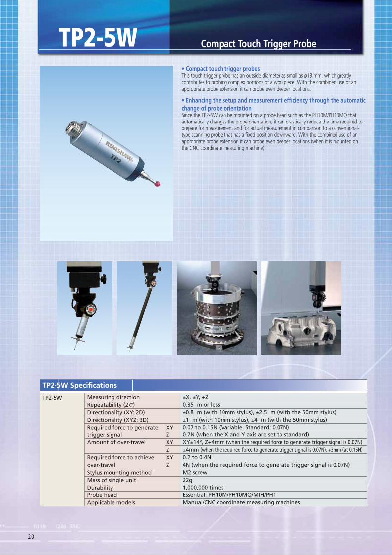
This touch trigger probe has an outside diameter as small as ø13 mm, which greatly contributes to probing complex portions of a workpiece. With the combined use of an appropriate probe extension it can probe even deeper locations.
change of probe orientationSince the TP2-5W can be mounted on a probe head such as the PH10M/PH10MQ that automatically changes the probe orientation, it can drastically reduce the time required to prepare for measurement and for actual measurement in comparison to a conventional-type scanning probe that has a fixed position downward. With the combined use of an appropriate probe extension it can probe even deeper locations (when it is mounted on the CNC coordinate measuring machine).
Measuring directionRepeatability (2 )Directionality (XY: 2D)Directionality (XYZ: 3D)Required force to generatetrigger signalAmount of over-travel
Required force to achieveover-travelStylus mounting methodMass of single unitDurabilityProbe headApplicable models
XYZXYZXYZ
±X, ±Y, +Z0.35 m or less±0.8 m (with 10mm stylus), ±2.5 m (with the 50mm stylus)±1 m (with 10mm stylus), ±4 m (with the 50mm stylus)0.07 to 0.15N (Variable. Standard: 0.07N)0.7N (when the X and Y axis are set to standard)XY±14º, Z+4mm (when the required force to generate trigger signal is 0.07N)±4mm (when the required force to generate trigger signal is 0.07N), +3mm (at 0.15N)0.2 to 0.4N4N (when the required force to generate trigger signal is 0.07N)M2 screw22g1,000,000 times Essential: PH10M/PH10MQ/MIH/PH1Manual/CNC coordinate measuring machines
TP2-5W
TP2-5W Specifications
TP2-5W
21
der No. 916148]
Set configuration
123456789
1011121314151617181920
0.0220.1250.0240.0570.0860.00040.00040.00030.00050.00440.0050.0050.0020.006
1.30.1
0.010.2
0.050.05
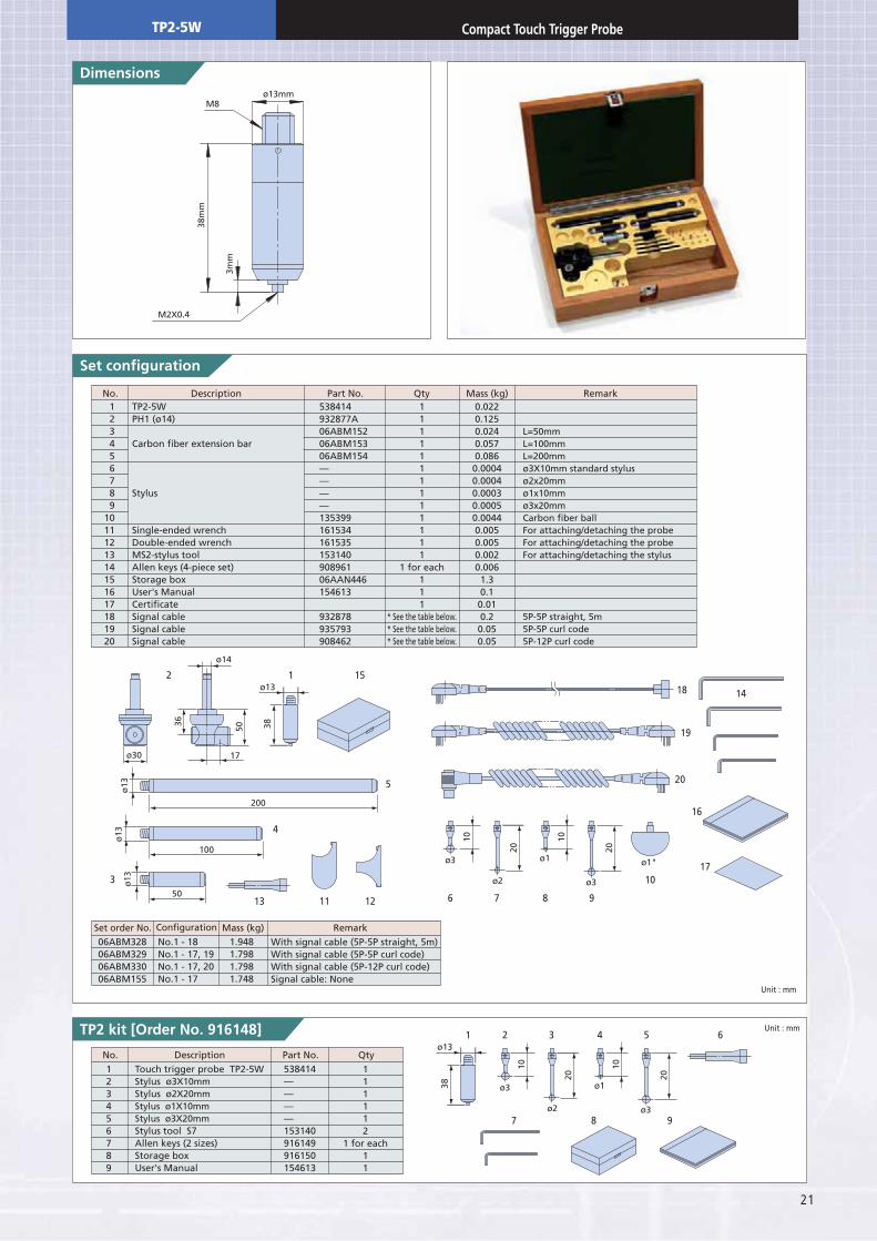
TP2-5WPH1 (ø14)
Carbon fiber extension bar
Stylus
Single-ended wrenchDouble-ended wrenchMS2-stylus toolAllen keys (4-piece set)Storage boxUser's ManualCertificateSignal cableSignal cableSignal cable
538414932877A06ABM15206ABM15306ABM154————13539916153416153515314090896106AAN446154613
932878935793908462
No. Description Qty Mass (kg) RemarkPart No.
L=50mmL=100mmL=200mmø3X10mm standard stylusø2x20mmø1x10mmø3x20mmCarbon fiber ballFor attaching/detaching the probeFor attaching/detaching the probeFor attaching/detaching the stylus
5P-5P straight, 5m5P-5P curl code5P-12P curl code
2 1 15
8 97
5
76 8 9
10
1418
19
20
16
17
121113
6
3
4
ø30
50
100
200
ø14
ø13
ø3
ø3
ø1"
ø2
ø1
ø13
ø13
ø13
17
36 38
1ø13
38
50
10
20
10
20
32 4 5
ø3
ø3ø2
ø1
10
20
10
20
123456789
111112
1 for each11
Touch trigger probe TP2-5WStylus ø3X10mmStylus ø2X20mmStylus ø1X10mmStylus ø3X20mmStylus tool S7Allen keys (2 sizes)Storage boxUser's Manual
538414————153140916149916150154613
No. Description QtyPart No.
With signal cable (5P-5P straight, 5m)With signal cable (5P-5P curl code)With signal cable (5P-12P curl code)Signal cable: None
06ABM32806ABM32906ABM33006ABM155
Set order No.No.1 - 18No.1 - 17, 19No.1 - 17, 20No.1 - 17
Configuration
1.9481.7981.7981.748
Mass (kg) Remark
M8
M2X0.4
ø13mm
3mm
38m
m
1111111111111
1 for each111
* See the table below.* See the table below.* See the table below.
Unit : mm
Unit : mm
TP2-5W
22
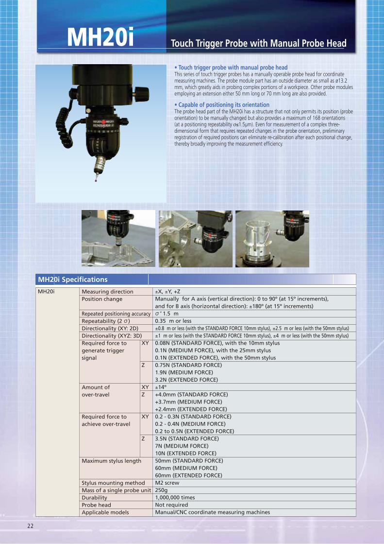
This series of touch trigger probes has a manually operable probe head for coordinate measuring machines. The probe module part has an outside diameter as small as ø13.2 mm, which greatly aids in probing complex portions of a workpiece. Other probe modules employing an extension either 50 mm long or 70 mm long are also provided.
The probe head part of the MH20i has a structure that not only permits its position (probe orientation) to be manually changed but also provides a maximum of 168 orientations (at a positioning repeatability σ≤1.5μm). Even for measurement of a complex three-dimensional form that requires repeated changes in the probe orientation, preliminary registration of required positions can eliminate re-calibration after each positional change, thereby broadly improving the measurement efficiency.
Measuring directionPosition change
Repeated positioning accuracyRepeatability (2 )Directionality (XY: 2D)Directionality (XYZ: 3D)Required force togenerate triggersignal
Amount ofover-travel
Required force toachieve over-travel
Maximum stylus length
Stylus mounting methodMass of a single probe unitDurabilityProbe headApplicable models
XY
Z
XYZ
XY
Z
±X, ±Y, +ZManually for A axis (vertical direction): 0 to 90º (at 15º increments),and for B axis (horizontal direction): ±180º (at 15º increments) ʺ1.5 m0.35 m or less±0.8 m or less (with the STANDARD FORCE 10mm stylus), ±2.5 m or less (with the 50mm stylus)±1 m or less (with the STANDARD FORCE 10mm stylus), ±4 m or less (with the 50mm stylus)0.08N (STANDARD FORCE), with the 10mm stylus0.1N (MEDIUM FORCE), with the 25mm stylus0.1N (EXTENDED FORCE), with the 50mm stylus0.75N (STANDARD FORCE)1.9N (MEDIUM FORCE)3.2N (EXTENDED FORCE)±14º+4.0mm (STANDARD FORCE)+3.7mm (MEDIUM FORCE)+2.4mm (EXTENDED FORCE)0.2 - 0.3N (STANDARD FORCE)0.2 - 0.4N (MEDIUM FORCE)0.2 to 0.5N (EXTENDED FORCE)3.5N (STANDARD FORCE)7N (MEDIUM FORCE)10N (EXTENDED FORCE)50mm (STANDARD FORCE)60mm (MEDIUM FORCE)60mm (EXTENDED FORCE)M2 screw250g1,000,000 timesNot requiredManual/CNC coordinate measuring machines
MH20i
MH20i Specifications
MH20i
23
Set Configuration
Standard for e
e
e
30
45
MH20i
0
15
MH20i
Probe module
MH20i MH20i
ø48mm
53m
m
77m
m19
.5m
m10
mm
5.7mm
ø14mm
123456789
111111111
0.250.010.05
0.0030.15
0.0010.0010.001
0.1
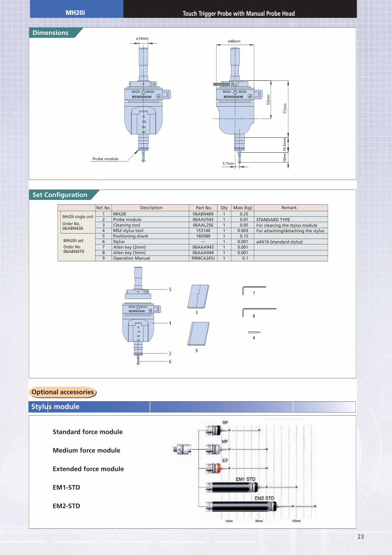
MH20iProbe moduleCleaning toolMS2-stylus toolPositioning shankStylusAllen key (2mm)Allen key (3mm)Operation Manual
06ABN46906AAV54306AAL256
153140160589
—06AAA94306AAA94499MCA265J
Ref. No. Description Qty Mass (kg) RemarkPart No.
STANDARD TYPEFor cleaning the stylus moduleFor attaching/detaching the stylus
ø4X10 (standard stylus)
MH20i single unit
Order No.06ABN436
MH20i setOrder No.06ABN470
5
30
45
MH20i
0
15
MH20i
111
3
9
7
8
4
2
6
MH20i
24
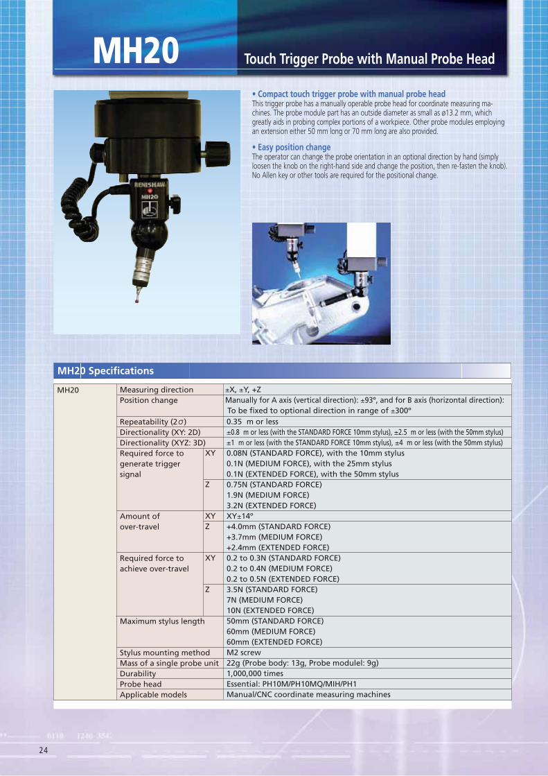
MH20This trigger probe has a manually operable probe head for coordinate measuring ma-chines. The probe module part has an outside diameter as small as ø13.2 mm, which greatly aids in probing complex portions of a workpiece. Other probe modules employing an extension either 50 mm long or 70 mm long are also provided.
The operator can change the probe orientation in an optional direction by hand (simply loosen the knob on the right-hand side and change the position, then re-fasten the knob). No Allen key or other tools are required for the positional change.
Repeatability (2 )Directionality (XY: 2D)Directionality (XYZ: 3D)Required force togenerate triggersignal
Amount ofover-travel
Required force toachieve over-travel
Maximum stylus length
Stylus mounting methodMass of a single probe unitDurabilityProbe headApplicable models
XY
Z
XYZ
XY
Z
0.35 m or less±0.8 m or less (with the STANDARD FORCE 10mm stylus), ±2.5 m or less (with the 50mm stylus)±1 m or less (with the STANDARD FORCE 10mm stylus), ±4 m or less (with the 50mm stylus)0.08N (STANDARD FORCE), with the 10mm stylus0.1N (MEDIUM FORCE), with the 25mm stylus0.1N (EXTENDED FORCE), with the 50mm stylus0.75N (STANDARD FORCE)1.9N (MEDIUM FORCE)3.2N (EXTENDED FORCE)XY±14º+4.0mm (STANDARD FORCE)+3.7mm (MEDIUM FORCE)+2.4mm (EXTENDED FORCE)0.2 to 0.3N (STANDARD FORCE)0.2 to 0.4N (MEDIUM FORCE)0.2 to 0.5N (EXTENDED FORCE)3.5N (STANDARD FORCE)7N (MEDIUM FORCE)10N (EXTENDED FORCE)50mm (STANDARD FORCE)60mm (MEDIUM FORCE)60mm (EXTENDED FORCE)M2 screw22g (Probe body: 13g, Probe modulel: 9g)1,000,000 timesEssential: PH10M/PH10MQ/MIH/PH1Manual/CNC coordinate measuring machines
MH20
MH20 Specifications
Measuring directionPosition change
±X, ±Y, +ZManually for A axis (vertical direction): ±93º, and for B axis (horizontal direction): To be fixed to optional direction in range of ±300º
25
1
23
0.3
0.10.01
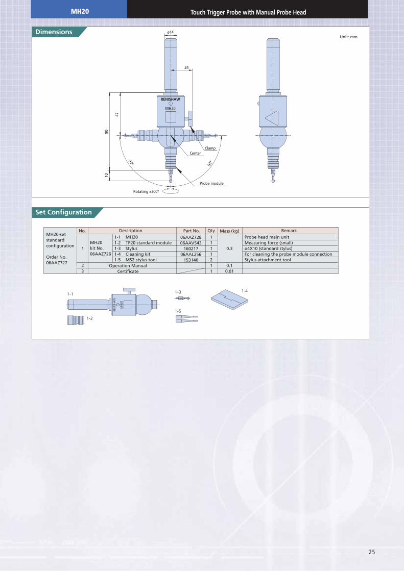
1-1 MH201-2 TP20 standard module1-3 Stylus1-4 Cleaning kit1-5 MS2-stylus tool
MH20-setstandardconfiguration
Order No.06AAZ727
MH20kit No.06AAZ726
06AAZ72806AAV543
16021706AAL256
153140
Probe head main unitMeasuring force (small)ø4X10 (standard stylus)For cleaning the probe module connectionStylus attachment tool
No. Description
Operation ManualCertificate
Qty Mass (kg) RemarkPart No.
1111211
MH
20
REN
ISH
AW
1-1
1-2
1-3
1-5
1-4
Set Configuration
MH2090
47
10
24
ø14
ClampCenter
Probe module
93º 93º
Rotating ±300º
Unit: mm
MH20
26
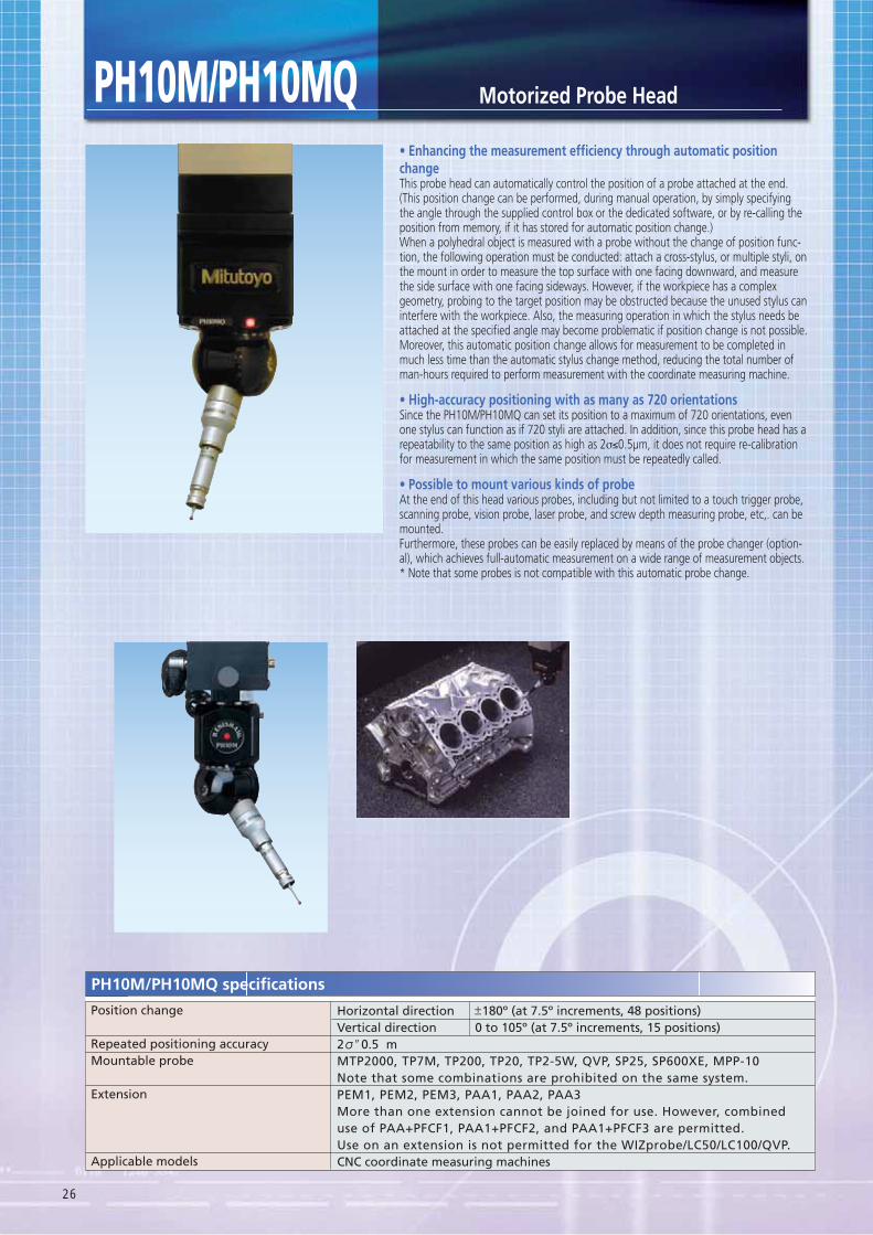
changeThis probe head can automatically control the position of a probe attached at the end. (This position change can be performed, during manual operation, by simply specifying the angle through the supplied control box or the dedicated software, or by re-calling the position from memory, if it has stored for automatic position change.) When a polyhedral object is measured with a probe without the change of position func-tion, the following operation must be conducted: attach a cross-stylus, or multiple styli, on the mount in order to measure the top surface with one facing downward, and measure the side surface with one facing sideways. However, if the workpiece has a complex geometry, probing to the target position may be obstructed because the unused stylus can interfere with the workpiece. Also, the measuring operation in which the stylus needs be attached at the specified angle may become problematic if position change is not possible. Moreover, this automatic position change allows for measurement to be completed in much less time than the automatic stylus change method, reducing the total number of man-hours required to perform measurement with the coordinate measuring machine.
Since the PH10M/PH10MQ can set its position to a maximum of 720 orientations, even one stylus can function as if 720 styli are attached. In addition, since this probe head has a repeatability to the same position as high as 2σ≤0.5μm, it does not require re-calibration for measurement in which the same position must be repeatedly called.
At the end of this head various probes, including but not limited to a touch trigger probe, scanning probe, vision probe, laser probe, and screw depth measuring probe, etc,. can be mounted.Furthermore, these probes can be easily replaced by means of the probe changer (option-al), which achieves full-automatic measurement on a wide range of measurement objects.* Note that some probes is not compatible with this automatic probe change.
Position change
Repeated positioning accuracyMountable probe
Extension
Applicable models
Horizontal directionVertical direction2 ʺ0.5 mMTP2000, TP7M, TP200, TP20, TP2-5W, QVP, SP25, SP600XE, MPP-10Note that some combinations are prohibited on the same system.PEM1, PEM2, PEM3, PAA1, PAA2, PAA3More than one extension cannot be joined for use. However, combineduse of PAA+PFCF1, PAA1+PFCF2, and PAA1+PFCF3 are permitted.Use on an extension is not permitted for the WIZprobe/LC50/LC100/QVP.CNC coordinate measuring machines
180º (at 7.5º increments, 48 positions)0 to 105º (at 7.5º increments, 15 positions)
PH10M/PH10MQ specifications
Motorized Probe HeadPH10M/PH10MQ
27
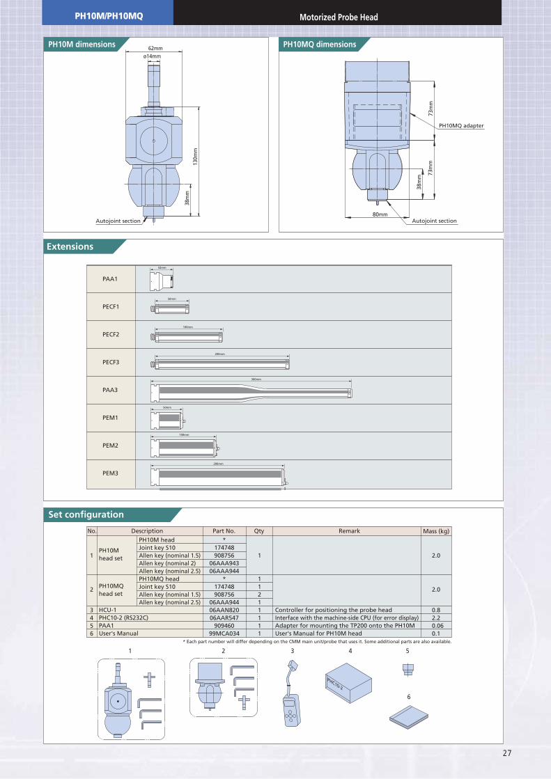
Set configuration
Autojoint section
62mmø14mm
130m
m38
mm
Autojoint section
PH10MQ adapter
80mm
73m
m73
mm
38m
m
PH10M headJoint key S10Allen key (nominal 1.5)Allen key (nominal 2)Allen key (nominal 2.5)PH10MQ headJoint key S10Allen key (nominal 1.5)Allen key (nominal 2.5)
1
2
3456
Controller for positioning the probe headInterface with the machine-side CPU (for error display)Adapter for mounting the TP200 onto the PH10MUser's Manual for PH10M head
*174748908756
06AAA94306AAA944
*174748908756
06AAA94406AAN82006AAR547
90946099MCA034
2.0
2.0
0.82.20.060.1
1
11211111
No. Description Qty Mass (kg)RemarkPart No.
PH10Mhead set
HCU-1PHC10-2 (RS232C)PAA1User's Manual
PH10MQhead set
PHC10-2
1
6
2 3 4 5
* Each part number will differ depending on the CMM main unit/probe that uses it. Some additional parts are also available.
PAA1
PECF1
PECF2
PECF3
PAA3
PEM1
PEM2
PEM3
200mm
100mm
50mm
300mm
32mm
200mm
100mm
50mm
PH10M/PH10MQ Motorized Probe Head
28
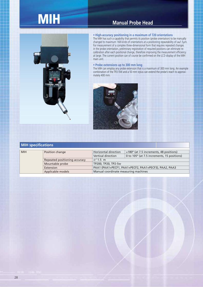
MIH Manual Probe Head
The MIH has such a capability that permits its position (probe orientation) to be manually changed to maximum 168 kinds of orientations at a positioning repeatability of σ≤1.5μm. For measurement of a complex three-dimensional form that requires repeated changes in the probe orientation, preliminary registration of required positions can eliminate re-calibration after each positional change, therefore improving the measurement efficiency at large. The current position can of course be confirmed on the LCD display of the MIH main unit.
The MIH can employ any probe extension that is a maximum of 300 mm long. An example combination of the TP2-5W and a 50 mm stylus can extend the probe’s reach to approxi-mately 400 mm.
Position change
Repeated positioning accuracyMountable probeExtensionApplicable models
±180º (at 7.5 increments, 48 positions)0 to 105º (at 7.5 increments, 15 positions)
Horizontal directionVertical direction ʺ1.5 mTP200, TP20, TP2-5wPAA1 (PAA1+PECF1, PAA1+PECF2, PAA1+PECF3), PAA2, PAA3Manual coordinate measuring machines
MIH
29
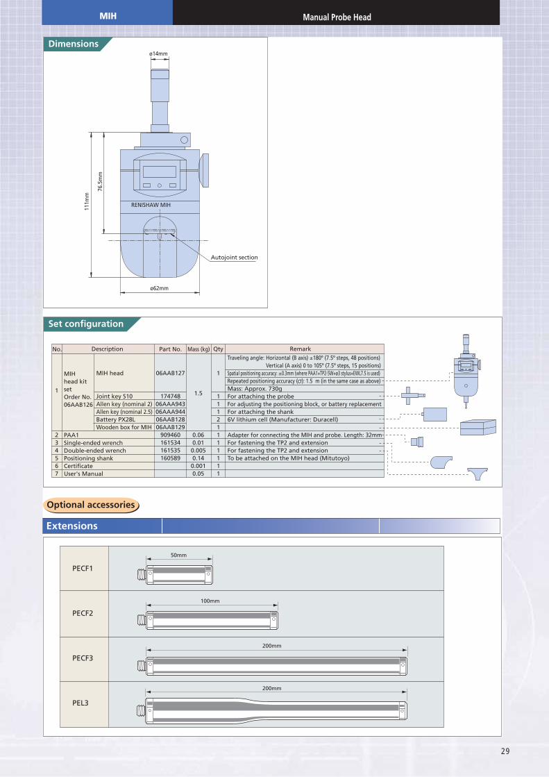
Set configuration
MIH head
Joint key S10Allen key (nominal 2)Allen key (nominal 2.5)Battery PX28LWooden box for MIH
1
234567
Traveling angle: Horizontal (B axis) ±180º (7.5º steps, 48 positions)Vertical (A axis) 0 to 105º (7.5º steps, 15 positions)
Spatial positioning accuracy: ±0.3mm (where PAA1+TP2-5W+ø3 stylus+EWL7.5 is used)Repeated positioning accuracy ( ): 1.5 m (in the same case as above)Mass: Approx. 730gFor attaching the probeFor adjusting the positioning block, or battery replacementFor attaching the shank6V lithium cell (Manufacturer: Duracell)
Adapter for connecting the MIH and probe. Length: 32mmFor fastening the TP2 and extensionFor fastening the TP2 and extensionTo be attached on the MIH head (Mitutoyo)
06AAB127
17474806AAA94306AAA94406AAB12806AAB129
909460161534161535160589
1.5
0.060.010.0050.140.0010.05
1
11121111111
No. Description QtyMass (kg) RemarkPart No.
MIHhead kitsetOrder No.06AAB126
PAA1Single-ended wrenchDouble-ended wrenchPositioning shankCertificateUser's Manual
RENISHAW MIH
Autojoint section
76.5
mm
ø14mm
111m
m
ø62mm
PECF1
PECF2
PECF3
PEL3
200mm
200mm
100mm
50mm
MIH Manual Probe Head
30
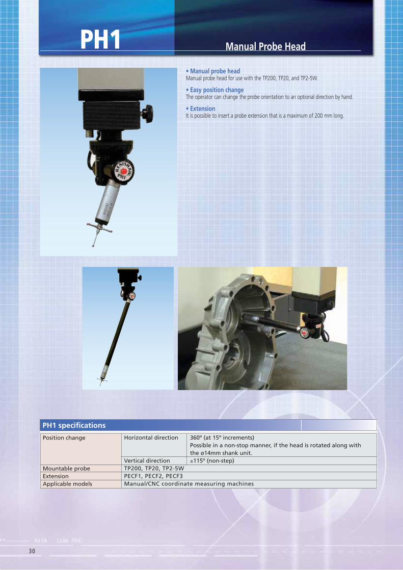
Manual probe head for use with the TP200, TP20, and TP2-5W.
The operator can change the probe orientation to an optional direction by hand.
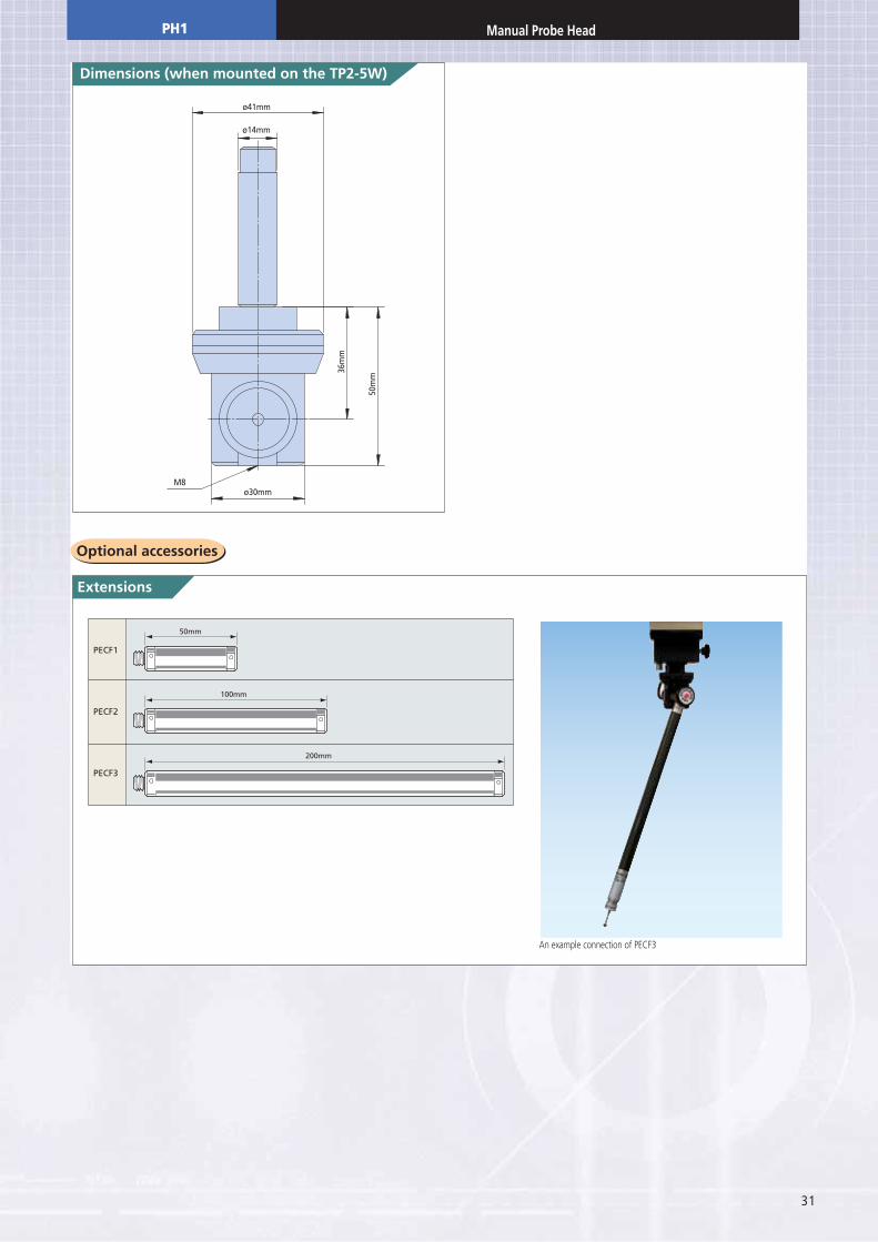
It is possible to insert a probe extension that is a maximum of 200 mm long.
Manual Probe Head
Position change
Mountable probeExtensionApplicable models
Horizontal direction
Vertical directionTP200, TP20, TP2-5WPECF1, PECF2, PECF3Manual/CNC coordinate measuring machines
360º (at 15º increments)Possible in a non-stop manner, if the head is rotated along withthe ø14mm shank unit.±115º (non-step)
PH1 specifications
PH1
31
M8ø30mm
50m
m
36m
m
ø14mm
ø41mm
PECF1
PECF2
PECF3
200mm
100mm
50mm
PH1 Manual Probe Head
An example connection of PECF3
32
ACR-3
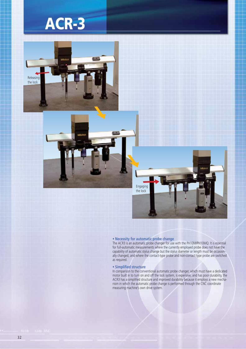
The ACR3 is an automatic probe changer for use with the PH10M/PH10MQ. It is essential for full-automatic measurements where the currently employed probe does not have the capability of automatic stylus change but the stylus diameter or length must be occasion-ally changed, and where the contact-type probe and non-contact type probe are switched as required.
In comparison to the conventional automatic probe changer, which must have a dedicated motor built in to turn on and off the lock system, is expensive, and has poor durability, the ACR3 has a simplified structure and improved durability because it employs a new mecha-nism in which the automatic probe change is performed through the CNC coordinate measuring machine’s own drive system.
Releasing the lock
Engaging the lock
33
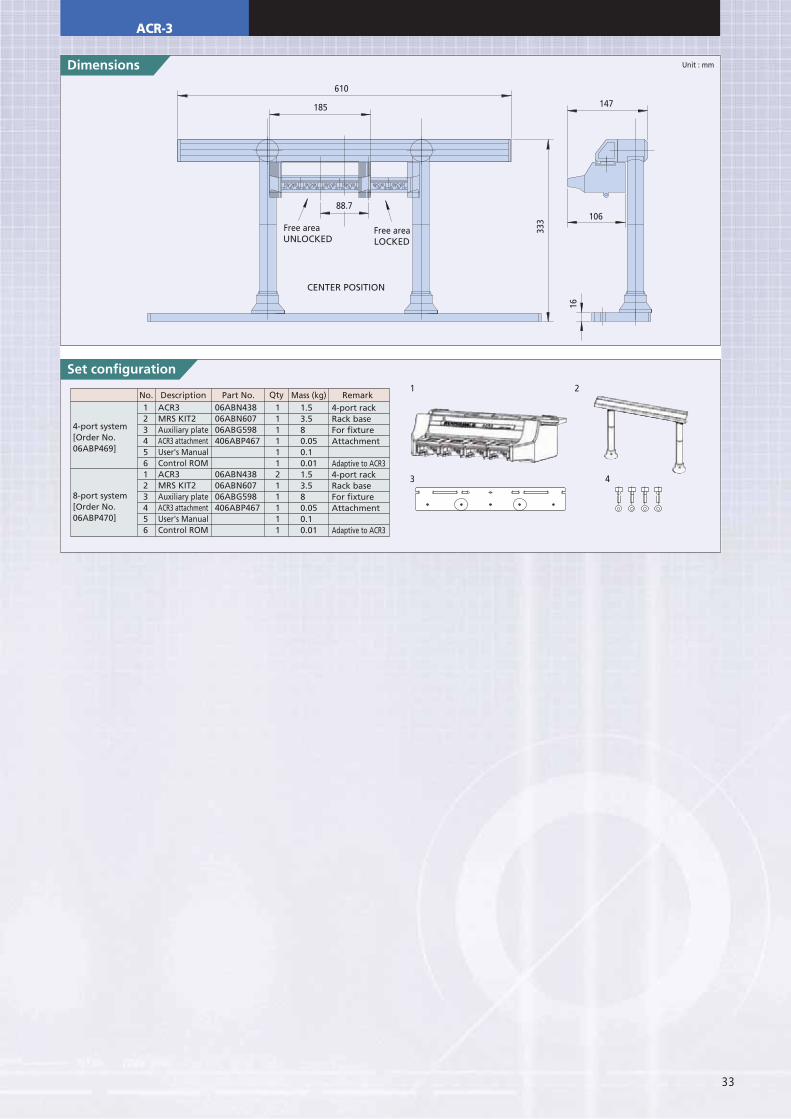
Set configuration
123456123456
1.53.580.050.10.011.53.580.050.10.01
ACR3MRS KIT2Auxiliary plateACR3 attachmentUser's ManualControl ROMACR3MRS KIT2Auxiliary plateACR3 attachmentUser's ManualControl ROM
06ABN43806ABN60706ABG598406ABP467
06ABN43806ABN60706ABG598406ABP467
No. Description Qty Mass (kg) RemarkPart No.4-port rackRack baseFor fixtureAttachment
Adaptive to ACR34-port rackRack baseFor fixtureAttachment
Adaptive to ACR3
111111211111
4-port system[Order No.06ABP469]
8-port system[Order No.06ABP470]
Unit : mm
1
3 4
2
Free area Free areaUNLOCKED LOCKED
CENTER POSITION
88.7
610
333
147
16
185
106
ACR-3
90.514
120 32
191
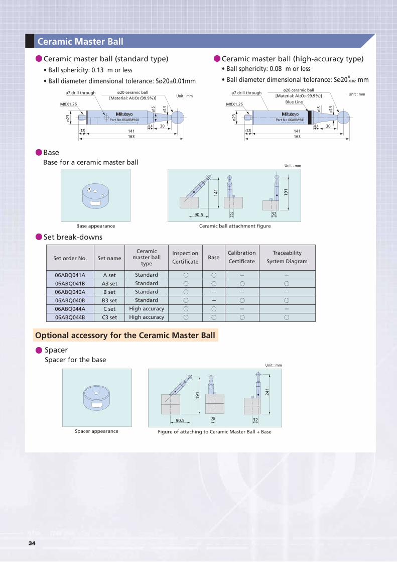
Ceramic master ball (standard type)m or less
±0.01mm
BaseBase for a ceramic master ball
Base appearance
Set break-downs
Optional accessory for the Ceramic Master Ball
Spacer
Spacer appearance
m or less
Set order No.
06ABQ041A
06ABQ041B
06ABQ040A
06ABQ040B
06ABQ044A
06ABQ044B
Set name
A set
A3 set
B set
B3 set
C set
C3 set
Standard
Standard
Standard
Standard
Ceramicmaster ball
type
Inspection
CertificateBase
Calibration
Certificate
Traceability
ø23
ø15
ø7.5
304(12)
163
ø20 ceramic ball2O3 (99.9%)]
141
ø23
ø15
ø7.5
30(12)
163141
ø20 ceramic ball2O3 (99.9%)]
1
20 32
241
90.5
191
0-0.02
Ceramic Master Ball
34
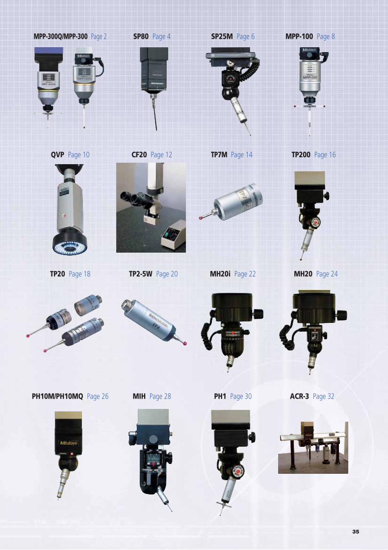
MPP-300Q/MPP-300 Page 2 SP80 Page 4 SP25M Page 6 MPP-100 Page 8
QVP Page 10 CF20 Page 12 TP7M Page 14 TP200 Page 16
TP20 Page 18 TP2-5W Page 20 MH20i Page 22 MH20 Page 24
PH10M/PH10MQ Page 26 MIH Page 28 PH1 Page 30 ACR-3 Page 32
35
Aurora, Illinois(Corporate Headquarters)
Westford, Massachusetts
Huntersville, North Carolina
Mason, Ohio
Plymouth, Michigan
City of Industry, California
One Number to Serve You Better1-888-MITUTOYO (1-888-648-8869)
Note: All information regarding our products, and in particular the illustrations, drawings, dimensional and performance data contained in this printed matter as well as other technical data are to be regarded as approximate average values. We therefore reserve the right to make changes to the corresponding designs. The stated standards, similar technical regulations, descriptions and illustrations of the products were valid at the time of printing. In addition, the latest applicable version of our General Trading Conditions will apply. Only quotations submitted by ourselves may be regarded as definitive.
Mitutoyo products are subject to US Export Administration Regulations (EAR). Re-export or relocation of Mitutoyo products may require prior approval by an appropriate governing authority.
Trademarks and RegistrationsDesignations used by companies to distinguish their products are often claimed as trademarks. In all instances where Mitutoyo America Corporation is aware of a claim, the product names appear in initial capital or all capital letters. The appropriate companies should be contacted for more complete trademark and registration information.
We reserve the right to change specifications and prices without notice.