problem-solving with industrial drawings: supporting...
TRANSCRIPT
Problem-Solving with Industrial Drawings: Supporting
Formal Graphics Language Development for Malaysian
Engineering Graduates*
COLIN BURVILL1, BRUCE FIELD1, ZULKEFLEE ABDULLAH2 and MAIZAM ALIAS31Department of Mechanical Engineering, School of Engineering, University of Melbourne, Australia. E-mail: [email protected] of Manufacturing Design, Faculty of Manufacturing Engineering, Universiti Teknikal Malaysia Melaka, Malaysia.
E-mail: [email protected] of Technical and Vocational Education, Universiti Tun Hussein Onn, Malaysia. E-mail [email protected]
The globalisation ofmanufacture has forcedmany developing countries inAsia to respond to the exacting requirements of
quality and interchangeability that involve complex and diverse conventions for graphical and geometrical product
specifications. Competing pressure for international recognition of engineering qualifications has reduced the time
available in Malaysian universities to teach a range of practical skills, including those of reading and interpreting
engineering drawings (RIED), although Malaysian industry has identified inadequacies in the RIED skills of recent
graduates. This paper reports the deliberate use of incidental learning to increase RIED skills in groups of undergraduate
engineering students by replacing the familiar line illustrations of parts andmachines in the learning tasks of a conventional
analytical subject with sets of formal engineering drawings. Participants who were engaged for 14 hours of practical
problem solving work in the subject and a parallel CAD-modelling subject, gained measurable skills in RIED. Since the
increase inparticipants’RIEDskill did not require alterations to the existing educational objectives of the subjects, the time
allocated to problem-solving within those subjects or additional RIED teaching expertise, an expansion of the approach is
recommended.
Keywords: incidental learning; graphics education; engineering drawings; problem based learning
1. Introduction
Malaysia is ideally placed to participate in south-
east Asia’s manufacturing boom.With a well estab-
lished western-style education system, ready access
to international transport routes, a stable economy,
widespread use of the English language, yet lowlabour costs, Malaysian industry is able to attract
manufacturing contracts from well beyond the
region [1]. Modern manufacturing demands high
quality, facilitating component interchangeability
and multi-site co-ordinated construction. The
detailed specifications for component geometry
and assembly are most commonly contained in
formal engineering drawings, typically preparedby the design originator and passed onto the man-
ufacturer. Consequently,Malaysian industry has to
respond to the demands of complex manufacturing
specifications that arise from diverse geographical
and geo-political locations.
While most of the graphical conventions for
manufacturing drawings are universal, there are
important local differences that must be accommo-dated by contract manufacturers. For example,
while ISO 128 (commonly used throughout
Europe and in most of Asia, including Malaysia)
is based on first angle projections, alternative stan-
dards such as the British BS888, United States
ASME Y14.3M, Japanese JIS B 0001 and Austra-
lian AS/NZS1100 use third angle projections. Most
education and training programs understandably
focus on their local standard. Nevertheless, it is
sometimes possible tomisread an engineering draw-
ing based on an unfamiliar projection system, and
thereby manufacture a ‘‘left hand version’’ of theintended product.
Evenwithin otherwise similar projection systems,
differences in the conventions used to simplify and
communicate complex shapes can give rise to errors.
The conventions for representing screw threads, for
example, involve the use of uniform width, full and
dashed lines in ASME Y14.3M, but alternating
width full lines in BS8888.It is apparent that in some countries, such as
Malaysia, there is a greater requirement for manu-
facturing engineers to be familiar with the drawing
conventions from elsewhere. This places additional
demands on the engineering education and accred-
itation process since a lack of familiarity with the
alternative conventions gives rise to potentially
costly errors.In this paper we identify the shortcomings in
graduate skill in reading and interpreting engineer-
ing drawings (RIED) that Malaysian industry has
raised and find that the existing undergraduate
manufacturing engineering program at a typical
* Accepted 15 May 2016.2172
International Journal of Engineering Education Vol. 32, No. 5(B), pp. 2172–2183, 2016 0949-149X/91 $3.00+0.00Printed in Great Britain # 2016 TEMPUS Publications.
Malaysian university does not develop RIED skill
much beyond that of an introductory drafting
course. We then show that a subtle adjustment to
the way otherwise conventional analytical subjects
are presented can improve undergraduates’ RIED
skill without altering the established curriculum,increasing student workload, or requiring any new
RIED teaching skills.
2. Research background and context: Theindustrial problem
2.1 Malaysian industry survey
After a small group of Malaysian engineers
expressed concern to the Universiti Teknikal
Malaysia Melaka (UTeM) about graduate engi-
neers’ capability in reading and interpreting engi-
neering drawings, the authors constructed an on-
line survey, exploring local industry’s requirementsin RIED skill and the deficits in those skills. The
survey questions were checked for validity with the
pilot group of engineers who raised the issue.
The survey comprised twelve pairs of questions,
seeking responses on a Likert scale. For example, a
question ‘‘My graduate engineers understand the
concept of third angle projection’’ was followed by
the question ‘‘I require my graduate engineers tounderstand the concept of third angle projection’’.
After sending the survey to 100 Malaysian com-
panies, we received 34 responses from supervisors
who averaged more than four years overseeing
engineering graduates. The Cronbach’s alpha
score for the questionnaire responses was 0.92,
indicating high consistency. While some of the
issues raised were not regarded as being especiallyimportant for all graduate manufacturing engineers
(such as an ability to read pipework diagrams), all
twelve desired graduate capabilities raised in the
survey were reported as being inadequate [2].
The three issuesofmost concern,withdeficitsofat
least 1.0 on thefive-pointLikert scalewere perceived
shortcomings in graduate ability to: (a) visualise the
3D form of an object represented in an orthogonalmulti-view drawing, (b) interpret orthogonal assem-
bly drawings, and (c) identify design faults from
drawings. There were real, but lesser concerns (in
excess of 0.6 deficit) about convention- and applica-
tion-specific shortcomings. The survey indicated
that the authors’ initial perception that the special
demands of Malaysian manufacturing industry for
advanced RIED skill may have been the root causeof its concern was incorrect. Graduates were per-
ceived to lack someof themost fundamental abilities
to read and interpret generic orthogonal drawings,
and especially to understand the three dimensional
relationships depicted in those drawings.
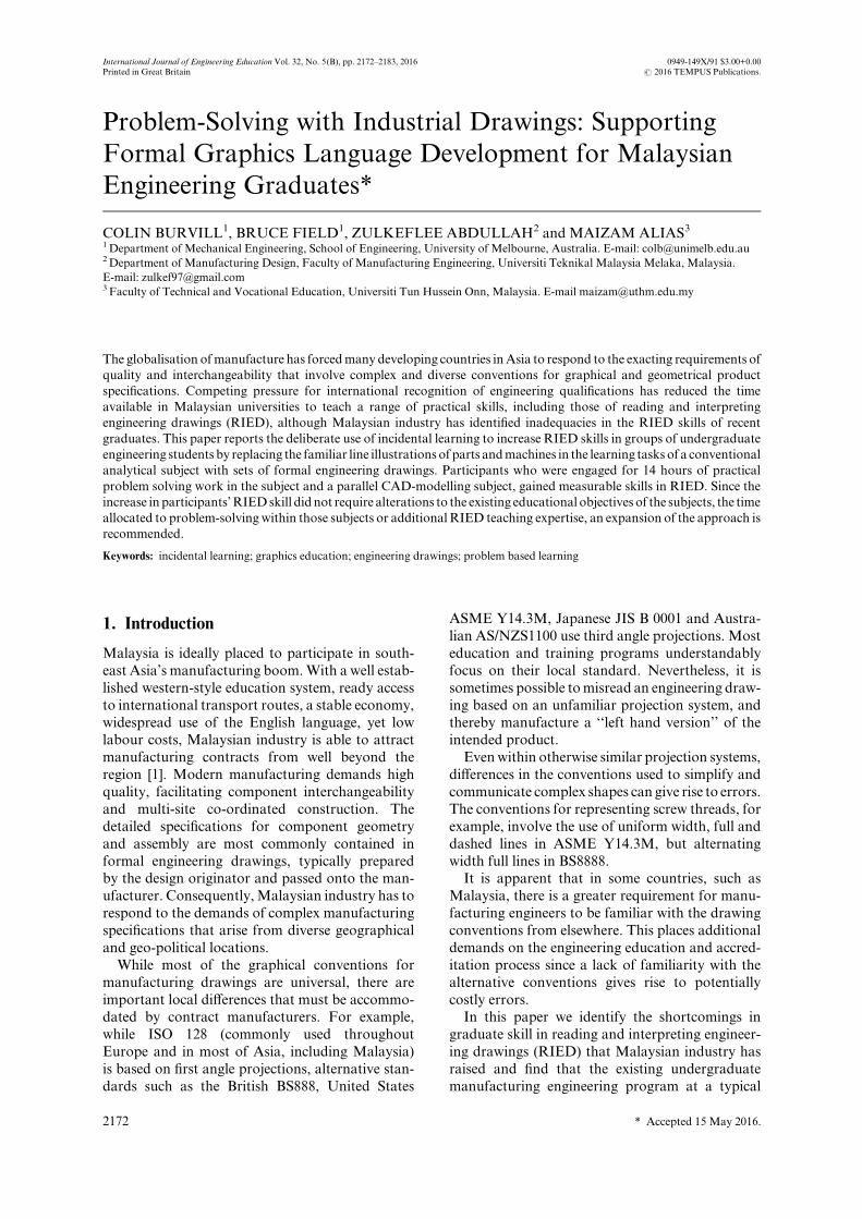
2.2 Malaysian undergraduate abilities in RIED
Following the industry survey, the authors sought
to discover if the principal perceived shortcomings
in graduate RIED skill existed during a typical
undergraduate engineering course. The Australian
authors had utilised an established RIED exercise[3] to explore learning and psychological issues in
the development of RIED skill, and made this test
[4] available to the Malaysian authors. The ten-
minute RIED test comprised a third angle dimen-
sioned drawing of a gear pump (Fig. 1) and 12
associated questions. This test was selected because
questions required interpretations of the 3D form
(five questions), the analysis of the assembled com-ponents (five questions), and practical issues (four
questions); questions that corresponded to the three
most critical issues raised in the industry survey.
After the RIED test was approved by the profes-
sional engineers who helped structure the industry
survey, and completed by a pilot group of volun-
teers at UTeM, it was undertaken by 252 engineer-
ing students from all year levels at UTeM. Theresults of this study [5] yielded three key findings.
First, RIED skill increased between the second
and third year levels at UTeM (t = 3.07, p < 0.002)
(Table 1). The investigation was not a longitudinal
study, so it is possible that this increase arose from
annual changes in matriculants’ general skill levels
or to teaching practices at UTeM during the pre-
vious years.However, all students had undertaken aformal studyof engineering drawing in thefirst year,
and most had engaged with engineering drawings
during a CAD/CAM subject in their third year. It
seemed plausible that the increase in RIED skill for
the last two years arose from activities during this
CAD/CAM subject.
Second, it was apparent that the UTeM students,
as a group, had performed significantly worse(t = 5.40, p < 0.0001) than third year students at
the University of Melbourne, who averaged 5.64
(SD 2.04, N = 180) [4] on the same test, but had
never been enrolled in a self-contained subject in
engineering drawing.
Third, four questions on the test were very poorly
answered at all year levels. Three of those questions
had a common theme in that they each required anunderstanding of the technology depicted in the
drawing. For example, no student was able to
nominate ‘the spacing for bolt holes for mounting
the pump’, apparently because they did not realise
that the slotted holes in the base were for mounting
purposes. Similarly, after determining the vertical
distance from the bottom of the pulley to the
mounting surface, very few students were able toappreciate that this feature would have important
consequences for mounting the pump on a base.
Students were also unable to find the clearance at
Problem-Solving with Industrial Drawings 2173
the tips of the gears, suggesting that the concept, orthe way dimensions were depicted, were not under-
stood.
Since student performance on this RIED test was
lower than that achieved byAustralian students, for
whom there were no universally poorly answered
questions, it was determined that RIED testing at
UTeM, aimed at measuring changes in RIED skill
following experimental interventions, should belimited to issues of spatial and representational
conventions, and should avoid technology-based
issues.
2.3 Trends in graphics education in Malaysia
Malaysian universities have signed the Washington
Accord [6]. Consequently, engineering courses
throughout the country fulfil requirements for arange of skills, principally analytical and knowl-
edge-based. In common with many Western uni-
versities, the demands for 21st century engineering
know-how have suppressed the more traditional
‘hands-on’ practical skills formerly mastered by
undergraduates, and have limited the time available
to develop deep familiarity with even one of the
drawing standards used in Malaysia.
Internationally, the requirements for graduateengineers to be competent at RIED have remained.
The abilities to create drawings, and to read and
interpret drawings, are separate competencies in
Europe [7] and in the USA [8]. Nevertheless, there
is a trend away from the undergraduate production
of hand-created engineering drawings, as firstly 2D
computer drawing software, then more recently 3D
modelling software have automated many of theactions needed to create engineering drawings since
2000 [9]. This automation alters the way in which
students learn RIED, with a decline both in psy-
chomotor demands and in opportunities for learn-
ing, as graphics studies decline from two or more
subjects to one or less [9]. At some universities (such
as at the Universities of Melbourne and Monash,
Australia), subjects for the formal preparation ofengineering drawings have been absorbed into other
studies, have been largely replaced with 3D CAD
modelling, and exist as lecture topics without sig-
nificant practical reinforcement.
With similar pressures on the graphics studies at
UTeM, where there remained one introductory
subject in engineering drawing, based on CAD
software, there did not appear to be any opportu-nity to address industry’s concerns about engineer-
ing graduates’ inadequate RIED skill through
Colin Burvill et al.2174
Fig. 1. Drawing of gear pump used in the RIED test to explore undergraduate skill at UTeM.
Table 1.Results from the RIED skill survey of four year levels ofengineering students at UTeM
Year level N Mean score/12 S.D.
1 70 3.20 1.542 78 3.19 1.543 44 3.95 0.744 60 3.78 1.40
adjustments to the formal content of engineering
programs.
2.4 Incidental learning in the development of RIED
skills: Australian experience
Even though formal graphics education and draft-
ing skills had declined at the Australian authors’
universities, it was apparent that their undergradu-
ate students developed reasonable RIED abilities[4]. At the University of Melbourne, mechanical
engineering students engaged with engineering
drawings sourced from local industry in projects
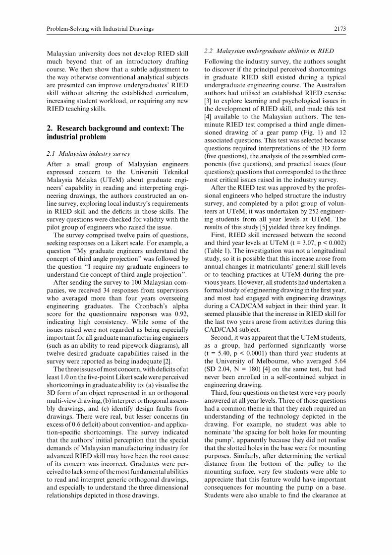
aimed at re-designingmajor assemblies. AtMonash
University, a whole year of engineering design
studies at the second year of the program utilised
semi-formal assembly drawings of increasing com-
plexity as the basis for a range of analytical tasks.The assembly drawing in Fig. 2, for example, was
used in an end-of-year formal examination to
supply data for separate questions of load analysis,
the selection of ball bearings, fatigue analysis,
welded joint design, bolted joint analysis and the
allocation of geometric and linear tolerances.
A separate technician-training program to
develop their understanding of the terminology
and flaws in injection moulding processes (a task
that involves complex assembly drawings) foundthat their RIED skills developed along with their
technical understanding, even though they were not
instructed in any aspects of formal engineering
drawing. Their learning was enhanced by the pre-
sence of the physical artefacts that were represented
in the formal drawings [10]. This gave further
indication that RIED skills might well develop
significantly if engineering students regularlyengaged with formal drawings during their non-
graphics studies.
Learning that occurs without formal engagement
with the discipline, while undertaking studies in
other areas has long been referred to as incidental
learning [11]. The term is also used to describe
learning that is a by-product of another activity,
Problem-Solving with Industrial Drawings 2175
Fig. 2. Semi-formal pump assembly drawing used at Monash University to set multiple analytical questions.
and learners are not always conscious of their
learning [12]. Most of the published research on
incidental learning arises from observations in the
workplace, since institutionalised learning (such as
at universities) is typically seen as being entirely
formal (ibid). Even though incidental learning isnow widely recognised, it is not clearly defined,
with definitions including ‘unexpected’ and
‘unplanned’ learning [13] contrasting with sugges-
tions that incidental learning can be ‘enhanced’ by
careful planning [14]. No formal studies appear to
indicate the types and extent of outcomes that can
arise from incidental learning, althoughmany of the
observers identify the development of affective [15]and interpersonal skills [16] in the workplace.
To the authors it appeared that the relatively
good RIED skills of the Australian undergraduates
may have arisen from their ongoing purposeful
exposures to formal engineering drawings while
they were undertaking unrelated (largely analytical)
learning tasks, and that such improvements in
RIED skill were due to incidental learning. Thisobservation led to the suggestion that useful gains in
RIED skillmight be forthcoming inUTeMstudents
if they, too, had a greater exposure to formal
engineering drawings. It might not be necessary
for their Professors to be especially skilled in
either producing or reading engineering drawings
as long as those drawings were professionally pro-
duced, sincemany of the conventions in engineeringdrawings are intuitive or easily deduced from their
context.
3. Research aim and hypothesis
The UTeM author was scheduled to teach a
machine element design subject to students at hisuniversity. Itwas hypothesised that if the students in
that subject were required to engage with formal
engineering drawings in order to extract informa-
tion needed to solve tutorial problems (in much the
same way as was required atMonash University, as
indicated in Fig. 2), they should gain a measurable
amount of RIED skill. Some of the UTeM students
were also undertaking a parallel study in CAD/CAM. In that subject, formal engineering drawings
were used to supply data to several learning and
assessment tasks, so it seemed plausible that some
RIED skill development might arise from this
experience as well. Taking both studies together,
students could be engaged with formal engineering
drawings for half of their formal contact time for a
four-week period during the semester, and it washypothesised that this exposure, amounting to some
14 hours in the classroom (only part of which would
be directly associated with drawings) would be
enough to develop additional, measurable RIED
skill by incidental learning. The aim of this investi-
gation was to test this hypothesis.
4. Methodology
4.1 Research design
Apre and post test quasi-experimental designwith a
control group was used in the study. A quasi-
experimental design is most suitable when the
research intent is to establish causal relationships
and a true experimental design is not appropriate. Atrue experimental design would have required
random selection and assignment of participants,
but mixing participants in unfamiliar company
could have posed a threat to the internal validity
of this study.
4.1.1 Participants
At UTeM, one group of 43 students (Treatment
group A) was enrolled in the machine element
design subject and in the CAD/CAM subject, for a
total of 14 contact hours with formal drawings. A
second group of 52 students (Treatment group B)was only enrolled in the machine element subject,
and engagedwith its formal drawings for a total of 8
contact hours. A third group of 59 engineering
students (the control group) was undertaking sepa-
rate studies for the duration of the research period,
but were not required to engage with any formal
engineering drawings for that period. All three
groups had otherwise similar university experiencesin the Manufacturing Engineering program at
UTeM, including the formal study of engineering
drawing in the first year of their program, and had
previously participated in the earlier RIED survey
(section 2.2).
4.2 Intervention
4.2.1 Machine elements design
The UTeM author developed new tutorial material
for a subject in machine element design, incorporat-
ing seven sets of formal A3 engineering drawings,including ten assembly drawings and 78 detail
drawings, with a total of 161 separate orthogonal
views. Tutorial problems in topics such as: joint
design, spring design and contact stresswere devised
to draw upon the dimensional, assembly and geo-
metric information contained in those drawings.
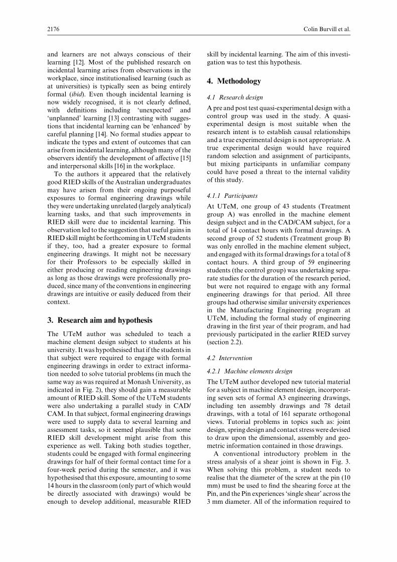
A conventional introductory problem in the
stress analysis of a shear joint is shown in Fig. 3.When solving this problem, a student needs to
realise that the diameter of the screw at the pin (10
mm) must be used to find the shearing force at the
Pin, and the Pin experiences ‘single shear’ across the
3 mm diameter. All of the information required to
Colin Burvill et al.2176
solve the problem, and no other data, is presented in
the text or on the drawing.
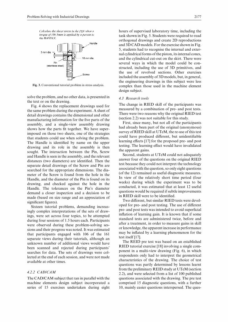
Fig. 4 shows the replacement drawings used for
the same problem during the experiment. A sheet of
detail drawings contains the dimensional and othermanufacturing information for the five parts of the
assembly, and a single-view assembly drawing
shows how the parts fit together. We have super-
imposed on those two sheets, one of the strategies
that students could use when solving the problem.
The Handle is identified by name on the upper
drawing and its role in the assembly is then
sought. The interaction between the Pin, ScrewandHandle is seen in the assembly, and the relevant
distances (two diameters) are identified. Then the
separate detail drawings of the Screw and Pin are
searched for the appropriate dimensions. The dia-
meter of the Screw is found from the hole in the
Handle, and the diameter of the Pin is found on its
drawing, and checked against the hole in the
Handle. The tolerances on the Pin’s diameterdemand a closer inspection and a decision to be
made (based on size range and an appreciation of
significant figures).
Sixteen tutorial problems, demanding increas-
ingly complex interpretations of the sets of draw-
ings, were set across four topics, to be attempted
during four sessions of 1.5 hours each. Participants
were observed during these problem-solving ses-sions and their progress was noted. It was estimated
that participants engaged with 106 of the 161
separate views during their tutorials, although an
unknown number of additional views would have
been scanned and rejected during participants’
searches for data. The sets of drawings were col-
lected at the end of each session, and were not made
available at other times.
4.2.2 CAD/CAM
The CAD/CAM subject that ran in parallel with the
machine elements design subject incorporated a
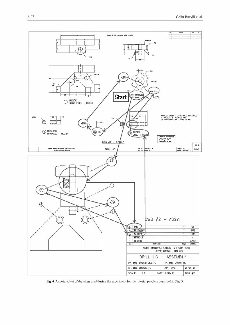
series of 15 exercises undertaken during eight
hours of supervised laboratory time, including the
task shown in Fig. 5. Students were required to read
orthogonal drawings and create 2D reproductions
and 3DCADmodels. For the exercise shown inFig.
5, students had to recognise the internal and exter-
nal cylindrical forms of the piston, its internal cones,and the cylindrical cut-out on the skirt. There were
several ways in which the model could be con-
structed, including the use of 3D primitives, and
the use of revolved sections. Other exercises
included the assembly of 3Dmodels, but, in general,
the engineering drawings in this subject were less
complex than those used in the machine element
design subject.
4.3 Research tools
The change in RIED skill of the participants was
measured by a combination of pre- and post tests.
There were two reasons why the original RIED test
(section 2.2) was not suitable for this study.
First, since many, but not all of the participantshad already been part of the original (anonymous)
survey ofRIED skill atUTeM, the re-use of this test
could have produced different, but unidentifiable
learning effects [17] for the proposed pre- and post
testing. The learning effect would have invalidated
the apparent gains.
Second, students at UTeM could not adequately
answer four of the questions on the original RIEDtest because they could not interpret the technology
associatedwith the question, so only eight questions
(of the 12) remained as useful diagnostic measures.
In view of the relatively short time period (four
weeks) during which the experiment was to be
conducted, it was estimated that at least 12 useful
questions would be required if subtle improvements
in RIED skill were to be identified.Two different, but similar RIED tests were devel-
oped for pre- and post testing. The use of different
pre- and post tests was intended to avoid superficial
inflation of learning gain. It is known that if some
standard tests are administered twice, before and
after a treatment, in order to measure gains in skill
or knowledge, the apparent increase in performance
may be inflated by a learning phenomenon for thetest itself [17].
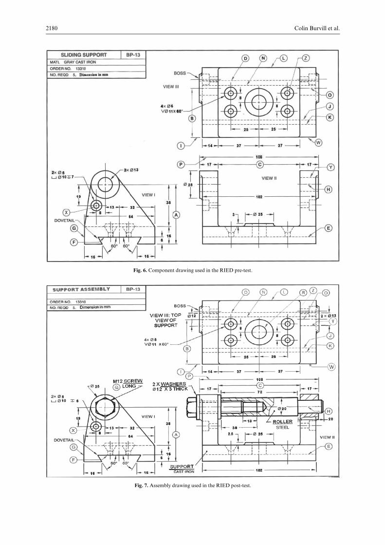
The REID pre test was based on an established
RIED tutorial exercise [18] involving a single com-
ponent in a multi-view drawing (Fig. 6), in which
respondents only had to interpret the geometrical
characteristics of the drawing. The choice of test
questions was partly determined by lessons learnt
from the preliminaryREID study atUTeM (section2.2), and were selected from a list of 100 published
questions associated with the drawing. The pre test
comprised 15 diagnostic questions, with a further
10, mainly easier questions interspersed. The ques-
Problem-Solving with Industrial Drawings 2177
Fig. 3. Conventional tutorial problem in stress analysis.
Colin Burvill et al.2178
Fig. 4. Annotated set of drawings used during the experiment for the tutorial problem described in Fig. 3.
tions (refer Appendix) were approved by the indus-
try-based engineers who assisted in the earlier
survey, refined with a voluntary group of ten under-graduate students (when a suitable test duration of
10 minutes was determined), required participants
to calculate dimensions by combining sizes across
different views (11 questions), associate lines and
shapes across views (5 questions), ascertain 2D
shapes (3 questions), identify edges (3 questions)
and other (3 questions).
The 10-minute RIED post test used in theresearch was a modified version of the RIED pre
test, with extra (but flawed) parts added to the
image, turning it into a dimensioned assembly
drawing (Fig. 7). The same 15 diagnostic questions
were retained, and a further five new questions
based on the assemblywere added (referAppendix).
The five additional questions were devised to throw
light on students’ abilities to interpret the assemblyand in particular to identify flaws in the design,
seeking to explore the three important issues raised
during the earlier industry survey (section 2.1).
4.3.1 Data gathering procedure
The RIED pre test was administered to the treat-
ment groups before they began the problem tasks
and to the control group. The UTeM author deliv-
ered the subject in machine element design for fourweeks, during which period the treatment groups
had access to the set of engineering drawings for
solving the tutorial problems. Due to the individua-
lised seating arrangement in the tutorial room,
participants in the treatment groups sometimes
found it awkward handling the A3 booklet of
drawings, although these participants nevertheless
appeared motivated by the challenge of interactingwith real engineering drawings. The treatment and
control groups completed the RIED post test six
weeks after they had taken the pre test.
5. Results and discussion
Analysis of the RIED pre test results found its
Cronbach’s Alpha to be 0.715, indicating good
internal consistency [19]. Item analysis determined
Problem-Solving with Industrial Drawings 2179
Fig. 5. Solid modelling task associated with the CAD/CAM subject.
Colin Burvill et al.2180
Fig. 7. Assembly drawing used in the RIED post-test.
Fig. 6. Component drawing used in the RIED pre-test.
the Difficulty and Discrimination Indices [20] for
each of the 15 questions in the pre test. The
Difficulty Index ranged from 0.25 to 0.75 for 14 of
the questions, indicating that most questions had
intermediate difficulty. No Discrimination Index
was negative, with all but two questions being
good discriminators (D > 0.2). A similar analysis
for the same 15 diagnostic questions in the RIEDpost test found that theDifficulty Index now ranged
from 0.26 to 0.79, and the Discrimination Indices
from 0.18 to 0.80. Students did not cope well with
the five assembly-based questions in the post test,
with Difficulty Indices between 0.11 and 0.32 and
Discrimination Indices from –0.04 to 0.33 (two
Indices were negative).
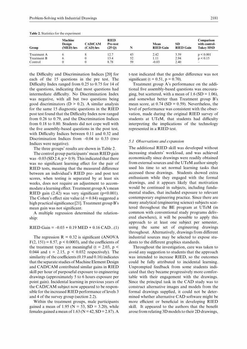
The three groups’ results are shown in Table 2.The control group participants’ mean RIED gain
was –0.03 (SD2.4, p> 0.9). This indicated that there
was no significant learning effect for the pair of
RIED tests, meaning that the measured difference
between an individual’s RIED pre- and post test
scores, when testing is separated by at least six
weeks, does not require an adjustment to accom-
modate a learning effect. Treatment groupA’smeanRIED gain (2.42) was very significant (p<0.001).
The Cohen’s effect size value (d = 0.84) suggested a
high practical significance [21]. Treatment groupB’s
mean gain was not significant.
A multiple regression determined the relation-
ship:
RIED Gain = –0.03 + 0.19 MED + 0.16 CAD...(1)
The regression R = 0.32 is significant (ANOVA
F(2, 151) = 8.57, p < 0.0003), and the coefficients of
the treatment types are meaningful (t = 2.03, p <0.044 and t = 2.15, p < 0.032 respectively). The
similarity of the coefficients (0.19 and 0.16) indicates
that the separate studies ofMachineElementDesign
and CAD/CAM contributed similar gains in RIED
skill per hour of purposeful exposure to engineering
drawings (approximately 5 to 6 hours exposure per
point gain). Incidental learning in previous years of
the CAD/CAM subject now appeared to be respon-sible for the increased RIED performance of levels 3
and 4 of the survey group (section 2.2).
Within the treatment groups, male participants
gained a mean of 1.95 (N = 53, SD = 3.20), while
females gained ameanof 1.63 (N=42, SD=2.87).A
t-test indicated that the gender difference was not
significant (t = 0.51, p = 0.70).
Treatment group A’s performance on the addi-
tional five assembly-based questions was encoura-
ging, but scattered, with a mean of 1.6 (SD = 1.06),
and somewhat better than Treatment group B’s
mean score, at 0.74 (SD = 0.59). Nevertheless, the
level of performance was consistent with the obser-vation, made during the original RIED survey of
students at UTeM, that students had difficulty
interpreting the implications of the technology
represented in a RIED test.
5.1 Observations and expansion
The additional RIED skill was developed without
increasing students’ workload, and was achieved
economically since drawings were readily obtained
from external sources and the UTeM author simply
used his time to set normal learning tasks that
accessed those drawings. Students showed extraenthusiasm while they engaged with the formal
drawings, and it appears likely that motivation
would be continued in subjects, including funda-
mental studies, that included exposure to relevant
contemporary engineering practice. Since there are
many analytical (engineering science) subjects scat-
tered throughout the BE program at UTeM (in
common with conventional study programs deliv-ered elsewhere), it will be possible to apply this
approach to at least one subject per semester,
using the same set of engineering drawings
throughout. Alternatively, drawings from different
industrial sources may be selected to expose stu-
dents to the different graphics standards.
Throughout the investigation, care was taken to
avoid any suggestion to students that the approachwas intended to increase RIED, so the outcomes
could be fully attributed to incidental learning.
Unprompted feedback from some students indi-
cated that they became progressively more comfor-
table with their engagement with the drawings.
Since the principal task in the CAD study was to
construct alternative images and models from the
formal drawings supplied, it could not be deter-mined whether alternative CAD software might be
more efficient or beneficial in developing RIED
skill. It appeared to the authors that the benefit
arose from relating 3Dmodels to their 2Ddrawings,
Problem-Solving with Industrial Drawings 2181
Table 2. Statistics for the experiment
Group
MachineDesign(MED) hrs
CAD/CAM(CAD) hrs
RIEDPre-test(25 Q) N
MeanRIED Gain
SDRIED Gain
Comparisonwith control-Tukey HSD
Treatment A 6 8 12.7 43 2.42 3.59 p < 0.001Treatment B 6 0 13.4 52 1.11 2.94 p < 0.15Control 0 0 8.78 59 -0.03 2.40 –
as with our earlier work with technicians [10], and
not the use of particular CAD software per-se. The
authors are aware that most of the drawings used in
the study presented both contemporary terminol-
ogy and basic mechanics of devices, and it seems
plausible that students would have gained addi-tional appreciation of these aspects via incidental
learning. Further work is needed in order to
quantify this possibility, and to determine if other
tools, such as computer simulations can contribute
in similar ways.
6. Conclusion and recommendation
When Malaysian undergraduate engineering stu-
dents were purposefully engaged with formal engi-neering drawings in order to extract data for solving
unrelatedanalyticalandCADproblems,theygained
measurableRIEDskill without requiring additional
graphics instruction. Since teachers do not need
special skills in RIED when they create learning
tasks from industrial drawings, an expansion of the
approachdemonstrated inour research, throughout
and across appropriate subjects in undergraduateengineering programs, is recommended.
References
1. G. Felker, Southeast Asian industrialism and the changingglobal production system, In K. Jayasuriya: Asian RegionalGovernance: Crisis and Change, London and New York,Routledge Curzon, 2004, p. 84.
2. Z. Abdullah, C. Burvill and B. Field, Identifying andquantifying industry perceptions of engineering drawingskills in novice Malaysian engineers, Proceedings of theInternational Conference on Engineering Design, ICED11,Copenhagen, 15–19 August 2011, pp. 1–12.
3. W. J. Luzadder and J. M. Duff, Introduction to engineeringdrawing, Prentice-Hall, 1993.
4. B.Field,C.Burvill and J.Weir, The impact of spatial abilitieson the comprehension of design drawings, InternationalConference on Engineering Design ICED 05, Melbourne,15–18 August 2005, pp. 1–15.
5. Z. Abdullah, B. Field and C. Burvill, Measuring Malaysianundergraduate skills in reading and interpreting engineeringdrawings, Proceedings of the International Conference onEngineering Design ICED 11, Copenhagen, 15–19 August2011, pp. 13–22.
6. H. Basri, A. B. CheMan,W.H.WanBadaruzzaman andM.J. M. Nor, Malaysia and the Washington accord: what it
takes for full membership, International Journal of Engineer-ing and Technology, 1(1), 2004, pp 64–73.
7. R. Metragalia, G. Baronio and V. Villa, Learning levels intechnical drawing education: proposal for an assessment gridbased on the European Qualifications Framework (EQF),Proceedings of the International Conference on EngineeringDesign, ICED 11, Copenhagen, 15–19August 2011, pp. 161–172
8. R. E. Barr, Engineering graphics outcomes for the globalengineer, Global Graphics—an Educational Perspective, 66thEDGDMid-YearConference, Texas, 22-24 January 2012, pp.109–125.
9. M. Sadowski and S. Sorby, A Delphi study as a first step indeveloping a concept inventory for engineering graphics,66th Mid-Year Meeting Proceedings, ASEE EngineeringDesign Graphics Division, Galveston TX, 22–24 January2012, pp. 126–132.
10. C. Burvill, T. Alirezaee and B. Field, Identifying and enhan-cing conceptual design capabilities, Proceedings of the Inter-national Conference on Engineering Design, ICED 05,Melbourne, 15–18 August 2005, paper 530.61.
11. J. Dewey, Experience and Education, Collier Books, NewYork, 1938.
12. V. J. Marsick and K. Watkins, Informal and incidentallearning in the workplace, London and New York, Routle-dge, 1990.
13. UNESCO, NFE-MIS Handbook, Developing a sub-Nationalnon-formal education management information system,Module 1, Paris, UNESCO, Division of Basic Education,2005.
14. C. A. Mealman, Incidental learning by adults in non tradi-tional degree program, 12th Annual Midwest Research-to-Practice Conference, ED 362 663, Columbus, Ohio StateUniversity, 22–24 September 1993.
15. V. J. Marsick and M. Volpe (eds), Informal learning on thejob, San Francisco, Berrett-Koehler Communications, 1999,pp. 80–96.
16. L. Bruce,M. K. Aring and B. Brand, Informal learning: Thenew frontier of employee and organizational development,Economic Development Review, 15(4), 1998, pp. 12–18.
17. C. Leopold, R. Gorska and S. A. Sorby, Experiences indeveloping the spatial visualization abilities, J. GeometryGraphics, 5(1), 2001, pp. 81–91.
18. T. P. Olivo and C. T. Olivo, Basic blueprint reading andsketching (8th edition), Cenage Learning, 2005.
19. J. Gliem and R. Gliem, Calculating, interpreting and report-ing Cronbach’s Alpha reliability coefficient for Likert-typescales, Midwest research-to-Practice Conference in Adult,Continuing and Community Education, Columbus, Oh, 8–10October 2003.
20. S. Fourie, B. Summers andR. Summers,Methods to evaluatethe quality of written pharmacology assessments, Universityof Limpopo, Polokwane, South Africa, 2006.
21. C. M. Schuele and L. M. Justice, The importance of effectsizes in the interpretation of research: Primer on Research:Part 3, The ASHA Leader, Retrieved Nov 12, 2013, http://www.asha.org/Publications/leader/2006/060815/f060815d.htm
ColinBurvill is a SeniorLecturer in theDepartment ofMechanicalEngineering atTheUniversity ofMelbourne (Australia)
with an earlier career as a practicing project and design engineer. Dr Burvill is coordinator and lecturer of all engineering
design subjects and final year (capstone) project. Dr. Burvill’s research interests include issues associated with ‘‘design for
innovation’’, encompassing aspects ranging from human cognition and creativity to mechanical systems design, bio-
mechanical design and environmental design. He has successfully integrated research outcomes with company needs on a
series of post-graduate and post-doctoral research and development projects.
Bruce Field is a consulting mechanical and forensic engineer who advises Australian industry and legal representatives on
aspects of machine design. Dr Field was formerly an Associate Professor inmechanical engineering atMonashUniversity
(Australia), with principal responsibilities in undergraduate professional education, including engineering design,
engineering drawing, and innovation processes, and has published widely on these topics. He is an honorary Associate
Professor at the University of Melbourne, where he co-supervises undergraduate and postgraduate projects.
Colin Burvill et al.2182

Zulkeflee Abdullah is a senior lecturer in the Faculty of Manufacturing Engineering, Technical University Malaysia
Melaka (UTeM), and recently graduated in PhD at theUniversity ofMelbourne. He joined academia after an early career
as a process engineer in a multinational company in Malaysia. His research interests are principally associated with
engineering design, ergonomics design, and design for manufacturing.
Maizam Alias is a professor of Technical and Vocational Education (TVE) in the Universiti Tun Hussein OnnMalaysia.
She obtained her PhD from the University of Surrey, UK and her Master’s degree in Structures from the National
University ofMalaysia. Professor Alias has more than fifteen years of teaching experience in civil engineering and TVE as
well as in supervising graduate students at the doctoral level. She publisheswidely in engineering education andTVEand is
on the editorial board member for several international journals including the Asean Journal of Engineering Education
and the Journal of Technical Education and Training. Her research interest includes teaching and learning in engineering
and inclusive education.
Problem-Solving with Industrial Drawings 2183
Appendix. RIED pre- and post test questions. Diagnostic question numbers bold italic
Pre test Q No Post test Q No Question
1 Determine height A2 What is the basic dimension C?3 1 What is the shape of the surface represented by the line Y?4 2 What line in VIEW III (top view) represents the surface G?5 What line in VIEW III (top view) represents the line H?6 3 What does the line E in the VIEW II (front view) represent? (an edge, a surface, or both)?7 What is the outside diameter of the BOSS?8 How deep is the DOVETAIL machined?9 What is the angle to the horizontal at which the DOVETAIL is machined?10 4 Is W an edge, a surface, or both?11 What surface in VIEW I (side view) is represented by line E?12 5 Determine dimension B13 6 How wide is the opening in the DOVETAIL?14 7 What is the shape of the region labelled Z?15 Is J an edge, a surface, or both?16 8 Is line J above, below, or at the same level as line K?17 9 How many BOSSES are shown?18 E corresponds to which line(s) in VIEW III?19 10 What lines in the VIEW III (top view) represent the DOVETAIL slot?20 How far off the centre of the SLIDING SUPPORT in VIEW III is the centre of the two holes in the
BOSSES of the uprights?21 11 Give the diameter of the largest hole(s) in VIEW III (top view)22 12 Give the diameter of the stepped (counterbored) holes23 13 What are the dimensions of the holes with the conical (countersunk) edges?24 14 Do the holes with the countersunk edges go right through?25 15 What is the shape of the region labelled X?
16 Find two design flaws with the rotating ROLLER17 Find the incorrect dimension in VIEW II18 How many parts are there in the assembly?19 What is the diameter of Hole R?20 What is the length ‘Q’ of the SCREW (excluding the head)?