procedural skeletons: kinematic extensions to cga … · procedural skeletons: kinematic extensions...
TRANSCRIPT
Procedural Skeletons: Kinematic Extensions to CGA-Shape GrammarsMartin Ilcík∗ Stefan Fiedler∗ Werner Purgathofer∗ Michael Wimmer∗
Institute for Computer Graphics and AlgorithmsVienna Technical University
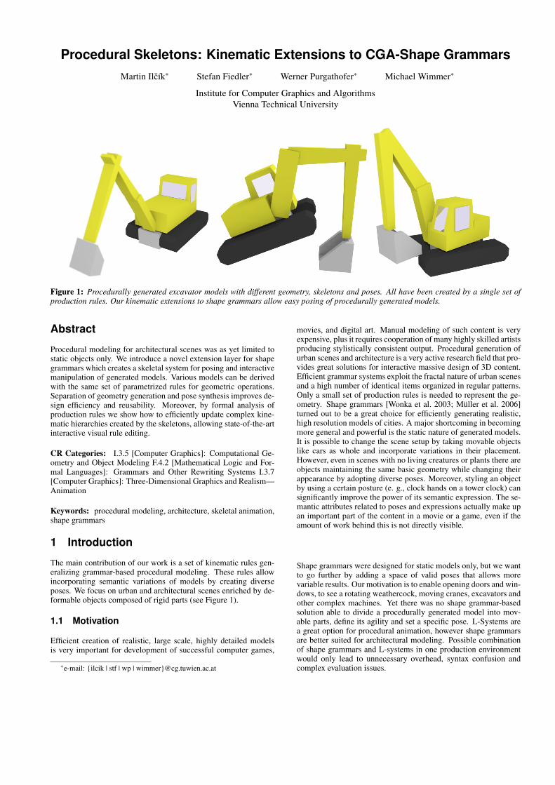
Figure 1: Procedurally generated excavator models with different geometry, skeletons and poses. All have been created by a single set ofproduction rules. Our kinematic extensions to shape grammars allow easy posing of procedurally generated models.
Abstract
Procedural modeling for architectural scenes was as yet limited tostatic objects only. We introduce a novel extension layer for shapegrammars which creates a skeletal system for posing and interactivemanipulation of generated models. Various models can be derivedwith the same set of parametrized rules for geometric operations.Separation of geometry generation and pose synthesis improves de-sign efficiency and reusability. Moreover, by formal analysis ofproduction rules we show how to efficiently update complex kine-matic hierarchies created by the skeletons, allowing state-of-the-artinteractive visual rule editing.
CR Categories: I.3.5 [Computer Graphics]: Computational Ge-ometry and Object Modeling F.4.2 [Mathematical Logic and For-mal Languages]: Grammars and Other Rewriting Systems I.3.7[Computer Graphics]: Three-Dimensional Graphics and Realism—Animation
Keywords: procedural modeling, architecture, skeletal animation,shape grammars
1 Introduction
The main contribution of our work is a set of kinematic rules gen-eralizing grammar-based procedural modeling. These rules allowincorporating semantic variations of models by creating diverseposes. We focus on urban and architectural scenes enriched by de-formable objects composed of rigid parts (see Figure 1).
1.1 Motivation
Efficient creation of realistic, large scale, highly detailed modelsis very important for development of successful computer games,
∗e-mail: {ilcik | stf | wp | wimmer}@cg.tuwien.ac.at
movies, and digital art. Manual modeling of such content is veryexpensive, plus it requires cooperation of many highly skilled artistsproducing stylistically consistent output. Procedural generation ofurban scenes and architecture is a very active research field that pro-vides great solutions for interactive massive design of 3D content.Efficient grammar systems exploit the fractal nature of urban scenesand a high number of identical items organized in regular patterns.Only a small set of production rules is needed to represent the ge-ometry. Shape grammars [Wonka et al. 2003; Müller et al. 2006]turned out to be a great choice for efficiently generating realistic,high resolution models of cities. A major shortcoming in becomingmore general and powerful is the static nature of generated models.It is possible to change the scene setup by taking movable objectslike cars as whole and incorporate variations in their placement.However, even in scenes with no living creatures or plants there areobjects maintaining the same basic geometry while changing theirappearance by adopting diverse poses. Moreover, styling an objectby using a certain posture (e. g., clock hands on a tower clock) cansignificantly improve the power of its semantic expression. The se-mantic attributes related to poses and expressions actually make upan important part of the content in a movie or a game, even if theamount of work behind this is not directly visible.
Shape grammars were designed for static models only, but we wantto go further by adding a space of valid poses that allows morevariable results. Our motivation is to enable opening doors and win-dows, to see a rotating weathercock, moving cranes, excavators andother complex machines. Yet there was no shape grammar-basedsolution able to divide a procedurally generated model into mov-able parts, define its agility and set a specific pose. L-Systems area great option for procedural animation, however shape grammarsare better suited for architectural modeling. Possible combinationof shape grammars and L-systems in one production environmentwould only lead to unnecessary overhead, syntax confusion andcomplex evaluation issues.
1.2 Approach overview
Our main step towards general semantic modeling with grammarsis a posing interface controlling the motion freedom limits and thecurrent model pose. We propose to store the kinematic informationas an additional attribute hierarchy in a separate graph in parallelto the original model derivation graph. This additional graph is askeleton represented by a hierarchy of joints and bone relationships– a technique widely used in skeletal animation [Maestri 1999]. Thenodes of this graph are the leaf nodes of the original model deriva-tion graph, while the edges represent kinematic joints. It structuresmesh parts stored in leaf nodes according to functional links be-tween them. One significant advantage of this data structure is itsmodularity.
Using the original CGA shape grammar [Müller et al. 2006], a sys-tem of procedural rules for a class of objects is very complex to im-plement and maintain and it is even more time-consuming to createa new set of rules whenever a pose changes. Our proposed kine-matic skeleton system is created automatically during the applica-tion of geometry production rules. This approach allows using theexisting rule sets while adding kinematic information to any proce-durally generated model without interfering with each other. Thesame geometry derivation might be at any time extended and trans-formed to various models with different semantic meaning. Theposing can be adapted through kinematic rules from the grammaror afterward as a post-processing step in a 3D modeling suite.
We provide an overview of related research mainly on the fieldof procedural architecture modeling in Section 2. Basics of CGAshape are shortly explained in Section 3. Our main contribution –the kinematic extensions – is presented in Section 4.
2 Related Work
Procedural modeling including all grammar based approaches hasbeen used for compression of object description and parametriza-tion for decades. Skeletal animation has become standard com-puter graphics knowledge as well. We focus on recent trends inboth fields, related to procedural architecture.
2.1 Procedural modeling of architecture
Many procedural techniques have been developed in context ur-banism and architectural design. The usage of grammars gainedpopularity when Prusinkiewicz and Lindenmayer showed, that forgeometric plant modeling impressive results can be achieved by us-ing L-systems [Prusinkiewicz and Lindenmayer 1991] as model-ing of biological objects is based on growth. Man-made structuresare better characterized as a sequence of partitioning steps describ-ing the spatial distributions of objects [Prusinkiewicz et al. 2001;Wonka et al. 2003]. For the analysis and construction of archi-tectural design, shape grammars [Stiny 1975] working with geo-metrical shapes instead of strings were successfully used by manyauthors [Downing and Flemming 1981; Beirão and Duarte 2005].Efficient procedural production of buildings uses shape grammarsadapted to the needs of computer graphics. Split grammars [Wonkaet al. 2003] are focused on adding geometric detail to façades, theirsuccessor CGA (Computer Generated Architecture) shape gram-mars [Müller et al. 2006] were developed to produce large scalemass models of buildings. Recently, structural feasibility for ma-sonry CGA shape models [Whiting et al. 2009] was achieved byadding mass and stress properties to the shapes. There is no moreneed for manual rule editing in text form, as an interactive visual ed-itor [Lipp et al. 2008] enables rapid content creation without both-ering with the grammar syntax. CGA shape can be considered asa state-of-the-art tool for procedural modeling of architecture. We
will examine this class of grammars in more detail in Section 3.More related techniques are discussed in a recent state-of-the-artreport [Vanegas et al. 2010].
2.2 Skeletal animation
In the field of robotics the problem of forward and inverse kine-matics has been extensively studied [Denavit and Hartenberg 1955]and numerous methods for calculating solutions have been devel-oped [Wang and Chen 1991; Zhao and Badler 1994], which are alsoused for posing and animating humanoid models [Smidt 1998]. Acommon method for animation of complex models uses a skeletalsystem to describe poses and movements [Maestri 1999]. Generallyspeaking, a kinematic skeleton consists of rigid sections connectedby rotational joints. Each section has a joint that connects it to aparent section, and the joints describe the rotation and translationof a section relative to its parent. Together they form a hierarchywhere the position of each section depends on the pose of all thosewhich precede it in the skeleton hierarchy. Different poses can beapplied to a model by rotating the joints, and it is possible to limitthe rotations of joints to an arbitrary range relative to a rest posi-tion. Kinematic skeletons were introduced to computer animationas a part of layered system for mesh deformations [Chadwick et al.1989], they are often derived from the model geometry [Bloomen-thal 1999]. Deformations of shapes are out the scope of this paper,as are many other related animation techniques focused mainly onhuman body animation [Collins and Hilton 2001]. Procedurallygenerated plants also use hierarchies of joints for animation of mo-tion in wind [Sakaguchi and Ohya 1999].
2.3 Grammar-based animation
L-Systems have been used not only for modeling growing ob-jects, but for animation of the growth process [Prusinkiewicz et al.1993] and environment interactions [Noser et al. 1992; Mech andPrusinkiewicz 1996] as well. Most of these approaches use rule se-lection driven by a time parameter with no explicit skeleton struc-ture. Extracted skeletons have been used for animation of humanorgan growth [Durikovic et al. 1998]. On a higher level, behav-ioral animation of virtual creatures including synthetic sensors forsensing the virtual environment [Noser and Thalmann 1999] can beachieved by using L-Systems.
3 Grammar-based mass modeling
CGA shape grammar is a well established approach for proceduralmodeling of architecture [Müller et al. 2006]. Our kinematic exten-sions build upon the original grammar rules, thus we would like tointroduce the basic concepts in this section.
3.1 CGA shape grammar overview
This language employs conditional, context-sensitive, stochasticevaluation of rules to retain realistic layouts of architectural ele-ments while allowing for a wide variety of buildings generated froma set of rules. The basic rules are general enough to support thedevelopment of rule sets for different architectural styles, and themodel generation does not require user input to select rules. Keyelements of CGA shape are the notion of shape, the definition andgeometric interpretation of basic rules, and the control of their eval-uation.
Each shape consists of a string symbol as well as geometric andnumeric attributes. Symbols relate to the semantics of shapes andcan identify them, especially for the purpose of selecting applicablerules. Geometric attributes define the visible form of a shape, and
YX
A
Local pivot
Joint placementScopeShape
Kinematic links
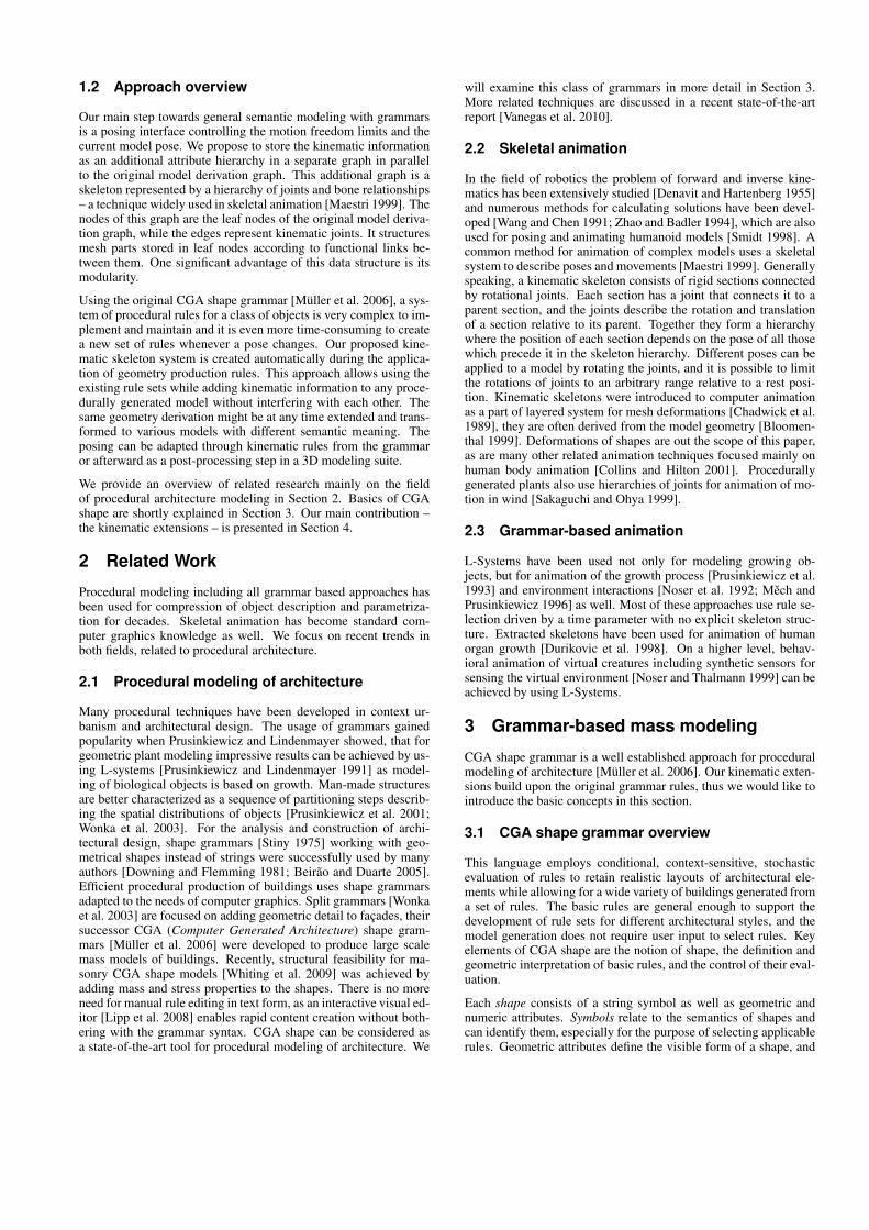
Figure 2: Shape, scope and skeleton. An elliptic shape is locatedinside a bounding box representing its scope. The scope is boundto a kinematic section with a joint (red circle), a parent on the leftand one child section on the right. Joints located at the origin ofeach local coordinate system (thin arrows) determine the kinematictransformation. Thick arrows represent the bones of the skeleton –rigid connections between adjacent sections.
most importantly include an oriented bounding box called scope.Shapes can be three- or lesser-dimensional. Numeric attributes al-low to parametrize rules and to further control the derivation pro-cess.
One part of the basic rules modifies the scope by translation, rota-tion or scaling, respectively, which also affects the geometry con-tained within the scope. The essential rule, a split rule, creates twoor more shapes of the same dimensionality by splitting the scopealong one or more of its axes. The repeat split rule works similarlybut creates as many shapes of the same kind as will fit into the orig-inal shape. Since both split rules should work well on a range ofdifferently sized scopes, some of the split sizes have to be scaled,but some elements are more suitable to scaling than others. To ac-commodate for this fact, split sizes can be absolute or relative tothe size of the original scope. Finally, the component split rule de-composes a shape into its lower-dimensional features, for exampleto create a shape for each face of a three-dimensional shape. Togo back to higher dimensions, shapes can be extruded, expressed inthe grammar as scaling along a scope axis.
CGA shape is a sequential grammar, which means that one rule isapplied at a time. The order of application is determined by thepriority of rules, so that rules applied earlier coarsely structure amodel, and later rules gradually add more details. Each rule canalso have preconditions based on numeric attributes of shapes todecide on its suitability. If several rules are applicable, one is se-lected based on a probability value for each rule.
4 Kinematic extensions
Starting from a set of original rules describing a static model, weadd kinematic rules to define movement limitations and the currentpose. Adding these extension rules requires defining how to dealwith kinematic structures when applying original rules as well. Wenow provide an overview of the kinematic rules and examine theinterpretation updates to original rules.
To simplify the kinematics integration to the existing rules system,each scope is now embedded in a kinematic section. It stores thejoint limitations, the current kinematic transformation and linkingto the parent section and children. We only allow creation of rigidbodies, thus scaling can be omitted. Joint positions and orientationsare relative to their parent’s coordinate system, not to the worldcoordinate system.
4.1 Skeleton grammar
Our main goal is to extend CGA grammars with new rules andconcepts to allow easy control of modeled shapes by a skeleton
A
C
D
A A
A C
DComponent splitExisting skeletonNew skeleton
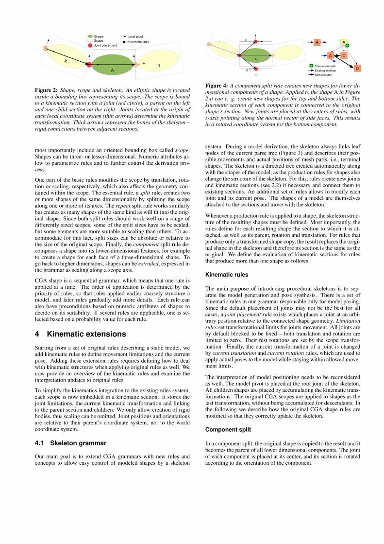
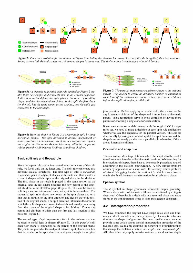
Figure 4: A component split rule creates new shapes for lower di-mensional components of a shape. Applied to the shape A in Figure2 it can e. g. create new shapes for the top and bottom sides. Thekinematic section of each component is connected to the originalshape’s section. New joints are placed at the centers of sides, withz-axis pointing along the normal vector of side faces. This resultsin a rotated coordinate system for the bottom component.
system. During a model derivation, the skeleton always links leafnodes of the current parse tree (Figure 3) and describes their pos-sible movements and actual positions of mesh parts, i.e., terminalshapes. The skeleton is a directed tree created automatically alongwith the shapes of the model, as the production rules for shapes alsochange the structure of the skeleton. For this, rules create new jointsand kinematic sections (see 2.2) if necessary and connect them toexisting sections. An additional set of rules allows to modify eachjoint and its current pose. The shapes of a model are themselvesattached to the sections and move with the skeleton.
Whenever a production rule is applied to a shape, the skeleton struc-ture of the resulting shapes must be defined. Most importantly, therules define for each resulting shape the section to which it is at-tached, as well as its parent, rotation and translation. For rules thatproduce only a transformed shape copy, the result replaces the origi-nal shape in the skeleton and therefore its section is the same as theoriginal. We define the evaluation of kinematic sections for rulesthat produce more than one shape as follows:
Kinematic rules
The main purpose of introducing procedural skeletons is to sep-arate the model generation and pose synthesis. There is a set ofkinematic rules in our grammar responsible only for model posing.Since the default placement of joints may not be the best for allcases, a joint placement rule exists which places a joint at an arbi-trary position relative to the connected shape geometry. Limitationrules set transformational limits for joints movement. All joints areby default blocked to be fixed – both translation and rotation arelimited to zero. Their rest rotations are set by the scope transfor-mation. Finally, the current transformation of a joint is changedby current translation and current rotation rules, which are used toapply actual poses to the model while staying within allowed move-ment limits.
The interpretation of model positioning needs to be reconsideredas well. The model pivot is placed at the root joint of the skeleton.All children shapes are placed by accumulating the kinematic trans-formations. The original CGA scopes are applied to shapes as thelast transformation, without being accumulated for descendants. Inthe following we describe how the original CGA shape rules aremodified so that they correctly update the skeleton.
Component split
In a component split, the original shape is copied to the result and itbecomes the parent of all lower dimensional components. The jointof each component is placed at its center, and its section is rotatedaccording to the orientation of the component.
Z Z
X A Y
Z
X A Y
Z
X A Y
X YSequential split
Current rotation
X
XRotation limit
Z
X A Y
X Y
X
Z
X A Y
X Y
X Y
Skeleton link
Skeleton root
Skeleton joint
Figure 3: Parse tree evolution for the shapes on Figure 2 including the skeleton hierarchy. First a split rule is applied, then two rotations.Strong arrows link skeletal structures, soft arrows shapes in parse tree. The skeleton root is emphasized with thick border.
B C D
Split direction A A
B C D
Sequential splitExisting skeletonNew skeleton
Figure 5: An example sequential split rule applied to Figure 2 cre-ates three new shapes and connects them in an ordered sequence.A direction vector defines the split planes, the order of resultingshapes and the placement of new joints. In this split the first shape(on the left) has the same parent as the original, and the child getsconnected to the last shape.
B
C
D
E
Split direction A A
C D E
Sequential splitExisting skeletonNew skeleton
B
Figure 6: Here the shape of Figure 2 is sequentially split by threehorizontal planes. The split direction is always independent ofbones direction. As shown here, any of the new sections can replacethe original section in the skeleton hierarchy. All other shapes re-sulting from the split become its direct or indirect children.
Basic split rule and Repeat rule
Since the repeat rule can be interpreted as a special case of the splitrule, we focus only on the latter one. The split rule can create twodifferent skeletal structures. The first type of split is sequential.It connects pairs of adjacent shapes with joints and thus creates achain of shapes which replaces the original shape in the skeleton.The first shape in the result is placed in the same section as theoriginal, and the last shape becomes the new parent of the origi-nal children in the skeleton graph (Figure 5). This can be seen assplitting a section into several ones, with joints between them. Thesequential split rule places new joints on the split planes and on aline that is parallel to the split direction and lies on the joint posi-tion of the original shape. The split direction influences the order inwhich the split shapes are connected and should usually point awayfrom the parent of the original shape to its children. Connectingparent and children to other than the first and last section is alsopossible (Figure 6).
The second type of split represents a fork in the skeleton and canbe used to model legs or fingers (Figure 7). In this parallel spliteach new shape is connected to the parent of the original shape.The joints are placed at the midpoint between split planes, on a linethat is parallel to the split direction and goes through the original
NO CHILDREN ALLOWED DURING A PARALLEL SPLIT
B
C
D
E
Split direction A A
C D E
Parallel splitExisting skeletonNew skeleton
B
Figure 7: The parallel split connects each new shape to the originalparent. This allows to create an arbitrary number of children ateach level of the skeleton hierarchy. There must be no childrenbefore the application of a parallel split.
joint position. Before applying a parallel split, there must not beany kinematic children of the shape and it must have a kinematicparent. These restrictions serve to avoid confusion of having moreparents or choosing a single one for each section.
If we want to reuse models created with the original CGA shaperules set, we need to make a decision at each split rule applicationwhether to take the sequential or the parallel version. This can bedone locally by taking a sequential split if the split direction and theshape bone are nearly parallel and a parallel split otherwise, if thereare no kinematic children.
Occlusion and snap rule
The occlusion rule interpretation needs to be adapted to the modeltransformations introduced by kinematic sections. While testing forintersections of shapes, these have to be correctly placed and rotatedaccording to the skeleton configuration. A very similar problemoccurs by application of a snap rule. It is closely related problemof visual debugging handled in section 4.3, which shows how toobtain the final kinematic transformation for an arbitrary shape.
Epsilon symbol
The ε symbol in shape grammars represents empty geometry.When a shape with no kinematic children is substituted by ε , it getsdestroyed. Otherwise it is dealt with as a terminal shape and staysstored in the configuration string to keep the skeleton consistent.
4.2 Interoperation properties
We have combined the original CGA shape rules with our kine-matics rules to encode a secondary hierarchy of semantic informa-tion into the shape configuration. For later considerations, we nowprovide some details about special interoperation properties of thetwo rule sets. We mainly examine the behavior of production rulesthat change the skeleton structure: basic splits and component split.All other rules only apply transformations to valid section dupli-
cates, thus we may implicitly exclude them from most of the proofs:scope rules, occlusion rule, snap rule, limitation rules and currentpose rules.
Kinematic skeleton basic properties
Definition A kinematic section is called valid only when it belongsto a leaf node of the parse tree.
Lemma 4.1 For each non-empty model there is always at least onevalid kinematic section.
Proof An axiom is always the first skeleton root. Each productionrule applied to a shape creates at least one new shape added to theskeleton instead of the original. The only way to destroy a shape isto replace its symbol by ε . In case the skeleton consists of a singleshape, substitution by ε leads to a contradiction by an empty resultmodel. If there are more shapes in skeleton it means the root hasat least one child. Because ε-shapes with kinematic children arepreserved, the root is never destroyed. �
Lemma 4.2 All valid kinematic sections of the parse graph are or-ganized in a single, rooted tree.
Proof An axiom is a single rooted tree. First we show by structuralinduction over parse trees, that the graph of all valid kinematic sec-tions is continuous. A Component split copies the previous validsection and adds new branches, a sequential split adds a sequenceof valid sections. Only a parallel split would cause problems bydividing the tree into several components when applied to a sectionwith no parent. Since we have defined the parallel split to be appli-cable only to shapes with a kinematic parent and no children, thatcase can not occur.
Second we show that there is only one root for each skeleton. If asection is the skeleton root i. e. it has no kinematic parent, each rule(except parallel split – not applicable to the skeleton root) producesexactly one child with no parent – becoming the new root. If a sec-tion has a kinematic parent, then all derived shapes are connectedto a parent as well. Similar to the proof of Lemma 4.1, if the root isreplaced by ε the shape is considered to be a terminal with emptygeometry.
Third we show that the graph is a tree i. e. it contains no cycles. Fora rooted tree it means that each node has exactly one kinematic par-ent. Kinematic links between sibling shapes created by an arbitraryrule satisfy this condition. Similar to the first proof part, inheritedkinematic links cause problems only by a parallel split applied toa shape with kinematic children. From the child’s point of view itwould split its single parent into several more. This is one of thereasons why we have decided to forbid application of parallel splitsto shapes with kinematic children. �
Corollary 4.3 No kinematic section has more than one parent.
Previous statements were related to the restrictions of parallel splits.An example of its wrong usage is depicted on Figure 8.
A A
C DWrong parallel splitExisting skeletonParse tree
YY
Y
Figure 8: Example of a parallel split applied wrong in two ways:First, it is applied to a section with no parent, thus the skeleton getstwo roots. Second, the Y node gets two parents.
AA
Bk CExisting skeleton
New skeleton
XY
XInternal skeleton links
SubtreeZ
Y
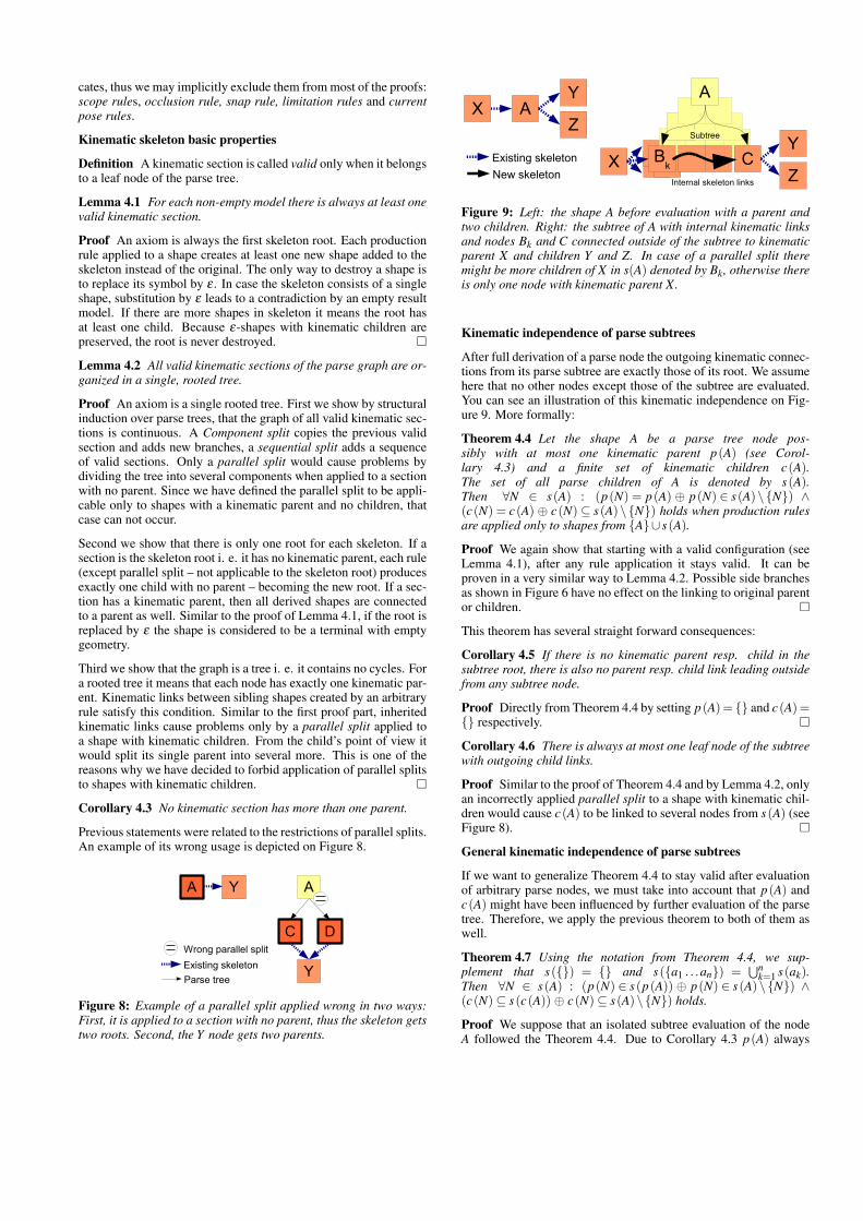
Z
Figure 9: Left: the shape A before evaluation with a parent andtwo children. Right: the subtree of A with internal kinematic linksand nodes Bk and C connected outside of the subtree to kinematicparent X and children Y and Z. In case of a parallel split theremight be more children of X in s(A) denoted by Bk, otherwise thereis only one node with kinematic parent X.
Kinematic independence of parse subtrees
After full derivation of a parse node the outgoing kinematic connec-tions from its parse subtree are exactly those of its root. We assumehere that no other nodes except those of the subtree are evaluated.You can see an illustration of this kinematic independence on Fig-ure 9. More formally:
Theorem 4.4 Let the shape A be a parse tree node pos-sibly with at most one kinematic parent p(A) (see Corol-lary 4.3) and a finite set of kinematic children c(A).The set of all parse children of A is denoted by s(A).Then ∀N ∈ s(A) : (p(N) = p(A) ⊕ p(N) ∈ s(A)\{N}) ∧(c(N) = c(A) ⊕ c(N)⊆ s(A)\{N}) holds when production rulesare applied only to shapes from {A}∪ s(A).
Proof We again show that starting with a valid configuration (seeLemma 4.1), after any rule application it stays valid. It can beproven in a very similar way to Lemma 4.2. Possible side branchesas shown in Figure 6 have no effect on the linking to original parentor children. �
This theorem has several straight forward consequences:
Corollary 4.5 If there is no kinematic parent resp. child in thesubtree root, there is also no parent resp. child link leading outsidefrom any subtree node.
Proof Directly from Theorem 4.4 by setting p(A)= {} and c(A)={} respectively. �
Corollary 4.6 There is always at most one leaf node of the subtreewith outgoing child links.
Proof Similar to the proof of Theorem 4.4 and by Lemma 4.2, onlyan incorrectly applied parallel split to a shape with kinematic chil-dren would cause c(A) to be linked to several nodes from s(A) (seeFigure 8). �
General kinematic independence of parse subtrees
If we want to generalize Theorem 4.4 to stay valid after evaluationof arbitrary parse nodes, we must take into account that p(A) andc(A) might have been influenced by further evaluation of the parsetree. Therefore, we apply the previous theorem to both of them aswell.
Theorem 4.7 Using the notation from Theorem 4.4, we sup-plement that s({}) = {} and s({a1 . . .an}) =
⋃nk=1 s(ak).
Then ∀N ∈ s(A) : (p(N) ∈ s(p(A)) ⊕ p(N) ∈ s(A)\{N}) ∧(c(N)⊆ s(c(A)) ⊕ c(N)⊆ s(A)\{N}) holds.
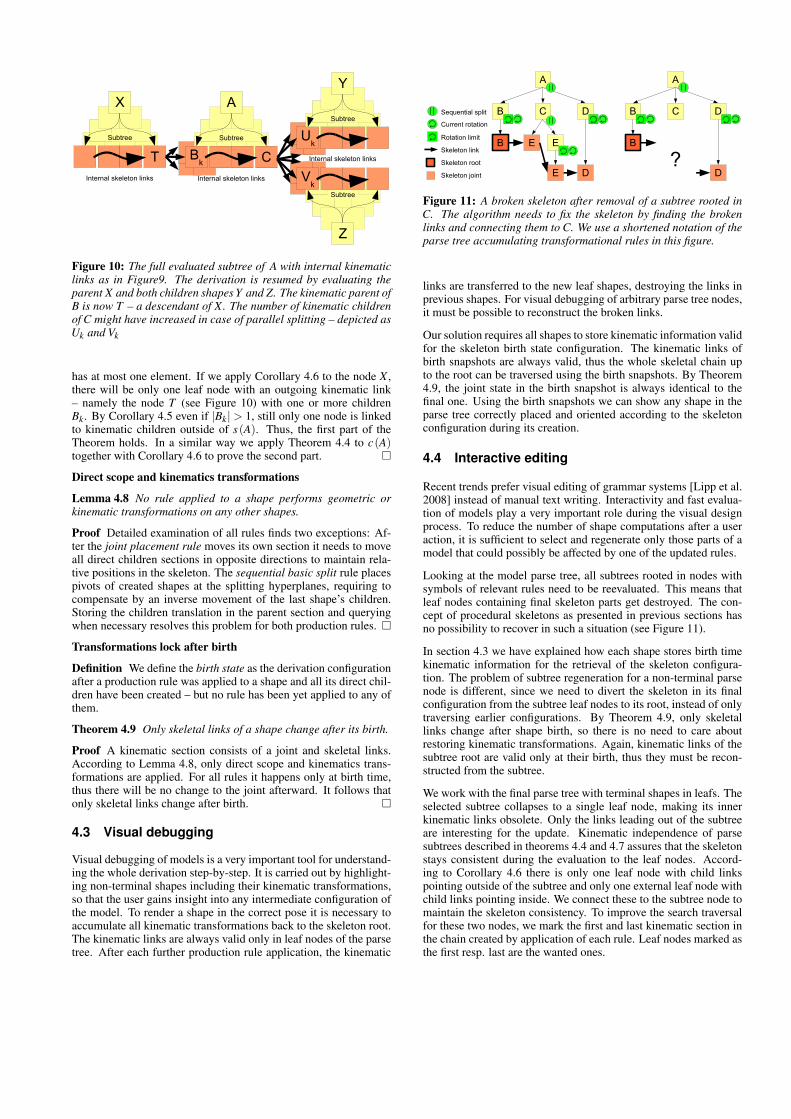
Proof We suppose that an isolated subtree evaluation of the nodeA followed the Theorem 4.4. Due to Corollary 4.3 p(A) always
A
Bk CInternal skeleton links
Subtree
X
TInternal skeleton links
Subtree
Y
Uk
Subtree
Z
Vk
Internal skeleton links
Subtree
Figure 10: The full evaluated subtree of A with internal kinematiclinks as in Figure9. The derivation is resumed by evaluating theparent X and both children shapes Y and Z. The kinematic parent ofB is now T – a descendant of X. The number of kinematic childrenof C might have increased in case of parallel splitting – depicted asUk and Vk
has at most one element. If we apply Corollary 4.6 to the node X ,there will be only one leaf node with an outgoing kinematic link– namely the node T (see Figure 10) with one or more childrenBk. By Corollary 4.5 even if |Bk| > 1, still only one node is linkedto kinematic children outside of s(A). Thus, the first part of theTheorem holds. In a similar way we apply Theorem 4.4 to c(A)together with Corollary 4.6 to prove the second part. �
Direct scope and kinematics transformations
Lemma 4.8 No rule applied to a shape performs geometric orkinematic transformations on any other shapes.
Proof Detailed examination of all rules finds two exceptions: Af-ter the joint placement rule moves its own section it needs to moveall direct children sections in opposite directions to maintain rela-tive positions in the skeleton. The sequential basic split rule placespivots of created shapes at the splitting hyperplanes, requiring tocompensate by an inverse movement of the last shape’s children.Storing the children translation in the parent section and queryingwhen necessary resolves this problem for both production rules. �
Transformations lock after birth
Definition We define the birth state as the derivation configurationafter a production rule was applied to a shape and all its direct chil-dren have been created – but no rule has been yet applied to any ofthem.
Theorem 4.9 Only skeletal links of a shape change after its birth.
Proof A kinematic section consists of a joint and skeletal links.According to Lemma 4.8, only direct scope and kinematics trans-formations are applied. For all rules it happens only at birth time,thus there will be no change to the joint afterward. It follows thatonly skeletal links change after birth. �
4.3 Visual debugging
Visual debugging of models is a very important tool for understand-ing the whole derivation step-by-step. It is carried out by highlight-ing non-terminal shapes including their kinematic transformations,so that the user gains insight into any intermediate configuration ofthe model. To render a shape in the correct pose it is necessary toaccumulate all kinematic transformations back to the skeleton root.The kinematic links are always valid only in leaf nodes of the parsetree. After each further production rule application, the kinematic
Sequential split
Current rotation
Rotation limit
Skeleton link
Skeleton root
Skeleton joint
A
B C D
B
D
E E
E
A
B C D
B
D?
Figure 11: A broken skeleton after removal of a subtree rooted inC. The algorithm needs to fix the skeleton by finding the brokenlinks and connecting them to C. We use a shortened notation of theparse tree accumulating transformational rules in this figure.
links are transferred to the new leaf shapes, destroying the links inprevious shapes. For visual debugging of arbitrary parse tree nodes,it must be possible to reconstruct the broken links.
Our solution requires all shapes to store kinematic information validfor the skeleton birth state configuration. The kinematic links ofbirth snapshots are always valid, thus the whole skeletal chain upto the root can be traversed using the birth snapshots. By Theorem4.9, the joint state in the birth snapshot is always identical to thefinal one. Using the birth snapshots we can show any shape in theparse tree correctly placed and oriented according to the skeletonconfiguration during its creation.
4.4 Interactive editing
Recent trends prefer visual editing of grammar systems [Lipp et al.2008] instead of manual text writing. Interactivity and fast evalua-tion of models play a very important role during the visual designprocess. To reduce the number of shape computations after a useraction, it is sufficient to select and regenerate only those parts of amodel that could possibly be affected by one of the updated rules.
Looking at the model parse tree, all subtrees rooted in nodes withsymbols of relevant rules need to be reevaluated. This means thatleaf nodes containing final skeleton parts get destroyed. The con-cept of procedural skeletons as presented in previous sections hasno possibility to recover in such a situation (see Figure 11).
In section 4.3 we have explained how each shape stores birth timekinematic information for the retrieval of the skeleton configura-tion. The problem of subtree regeneration for a non-terminal parsenode is different, since we need to divert the skeleton in its finalconfiguration from the subtree leaf nodes to its root, instead of onlytraversing earlier configurations. By Theorem 4.9, only skeletallinks change after shape birth, so there is no need to care aboutrestoring kinematic transformations. Again, kinematic links of thesubtree root are valid only at their birth, thus they must be recon-structed from the subtree.
We work with the final parse tree with terminal shapes in leafs. Theselected subtree collapses to a single leaf node, making its innerkinematic links obsolete. Only the links leading out of the subtreeare interesting for the update. Kinematic independence of parsesubtrees described in theorems 4.4 and 4.7 assures that the skeletonstays consistent during the evaluation to the leaf nodes. Accord-ing to Corollary 4.6 there is only one leaf node with child linkspointing outside of the subtree and only one external leaf node withchild links pointing inside. We connect these to the subtree node tomaintain the skeleton consistency. To improve the search traversalfor these two nodes, we mark the first and last kinematic section inthe chain created by application of each rule. Leaf nodes marked asthe first resp. last are the wanted ones.
Algorithm 1 Example part of a grammar for buildings with rotat-ing floors. RotLimits and CurrerntRot are variables for specifyingthe rotation of each floor. The skeleton is rooted at the basement,thus the rotations will be accumulated up to the top. The buildingvariations are shown in Figure 12.
BuildingRoot Subdiv(”Y ”,3.5){Basement|Floor}Floors Repeat(”Y ”,3a){Floor}Floor KinematicRotation(RotLimits,CurrentRot)
Comp(”side f aces”){FloorFacade}FloorFacade Repeat(”Y ”,1.5a){WindowPane}
. . .
The occlusion rule and snap rule are the only ones with globalscope. Their results are dependent from a number of collision testswith shapes resp. snap lines spread over the whole parse tree. Thus,our subtree evaluation method is inefficient here. We see space par-titioning as a possible option.
5 Results and performance
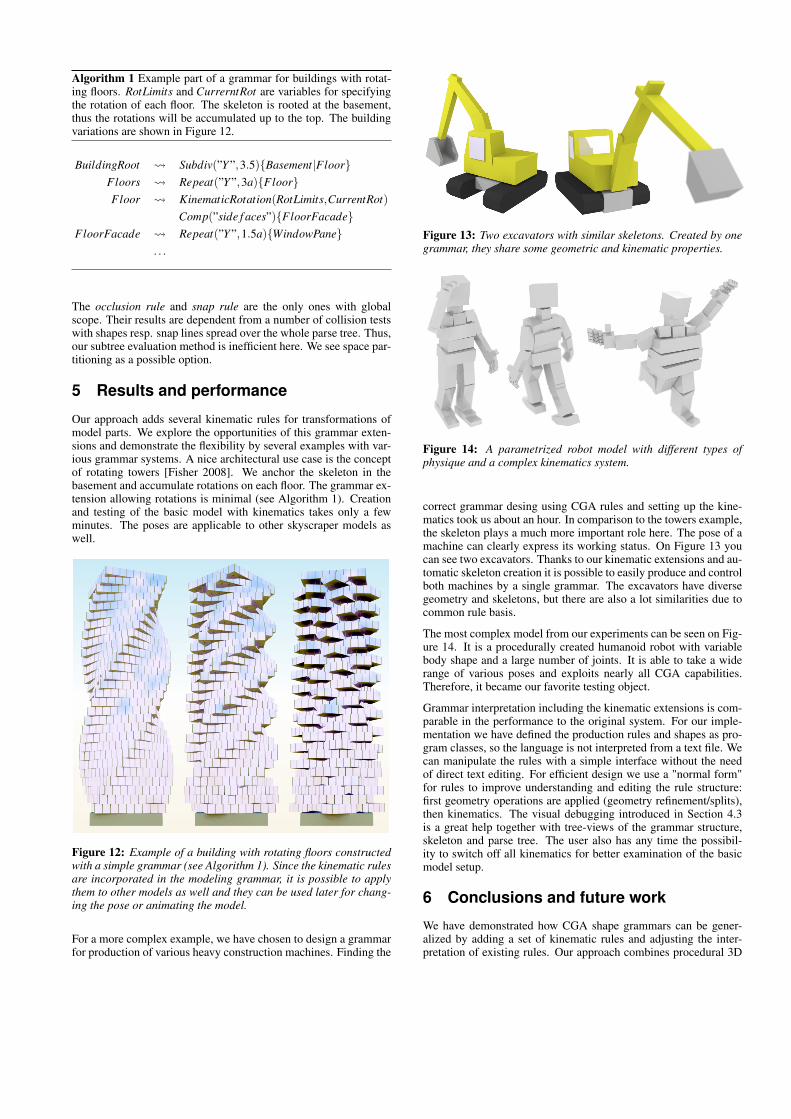
Our approach adds several kinematic rules for transformations ofmodel parts. We explore the opportunities of this grammar exten-sions and demonstrate the flexibility by several examples with var-ious grammar systems. A nice architectural use case is the conceptof rotating towers [Fisher 2008]. We anchor the skeleton in thebasement and accumulate rotations on each floor. The grammar ex-tension allowing rotations is minimal (see Algorithm 1). Creationand testing of the basic model with kinematics takes only a fewminutes. The poses are applicable to other skyscraper models aswell.
Figure 12: Example of a building with rotating floors constructedwith a simple grammar (see Algorithm 1). Since the kinematic rulesare incorporated in the modeling grammar, it is possible to applythem to other models as well and they can be used later for chang-ing the pose or animating the model.
For a more complex example, we have chosen to design a grammarfor production of various heavy construction machines. Finding the
Figure 13: Two excavators with similar skeletons. Created by onegrammar, they share some geometric and kinematic properties.
Figure 14: A parametrized robot model with different types ofphysique and a complex kinematics system.
correct grammar desing using CGA rules and setting up the kine-matics took us about an hour. In comparison to the towers example,the skeleton plays a much more important role here. The pose of amachine can clearly express its working status. On Figure 13 youcan see two excavators. Thanks to our kinematic extensions and au-tomatic skeleton creation it is possible to easily produce and controlboth machines by a single grammar. The excavators have diversegeometry and skeletons, but there are also a lot similarities due tocommon rule basis.
The most complex model from our experiments can be seen on Fig-ure 14. It is a procedurally created humanoid robot with variablebody shape and a large number of joints. It is able to take a widerange of various poses and exploits nearly all CGA capabilities.Therefore, it became our favorite testing object.
Grammar interpretation including the kinematic extensions is com-parable in the performance to the original system. For our imple-mentation we have defined the production rules and shapes as pro-gram classes, so the language is not interpreted from a text file. Wecan manipulate the rules with a simple interface without the needof direct text editing. For efficient design we use a "normal form"for rules to improve understanding and editing the rule structure:first geometry operations are applied (geometry refinement/splits),then kinematics. The visual debugging introduced in Section 4.3is a great help together with tree-views of the grammar structure,skeleton and parse tree. The user also has any time the possibil-ity to switch off all kinematics for better examination of the basicmodel setup.
6 Conclusions and future work
We have demonstrated how CGA shape grammars can be gener-alized by adding a set of kinematic rules and adjusting the inter-pretation of existing rules. Our approach combines procedural 3D
modeling with rigging, at a minimal cost. Creation of kinematicrelations is part of the modeling process. Therefore, the objects be-come easier to animate and kinematic characteristics can be easilyapplied to different models created by the same rule set.
Geometry and skeleton are treated as a two-layered data structure.We have shown an efficient update strategy for the coupled graphs,avoiding re-evaluation of the whole derivation tree. Efficient up-dates of rules with global scope are one of the next research topics.
There are still many problems and challenges, possible ways of im-proving the grammar systems and breaking away from architectureto general objects modeling. The most important topic for futurework is another improvement of rules interpretation. The shapes arenot connected when kinematic transformations are applied. Leaksand overlaps emerge as you can see on most of the pictures. Wewould like to treat shapes directly connected by kinematic sectionsnot only as independent rigid bodies, but also as one deformablemesh with geometric connectivity preserved depending on givenattributes. There are several problems to consider: preservation ofmass, extremal positions and collisions resolution. We also planto pursue our research goal of animated scenes where not only theposes but the whole movement would be generated by grammarbased controllers. The approach used for feasible masonry models[Whiting et al. 2009] shows how important it is to address staticsissues – in future we could deal with pose stability in a similar way.
Acknowledgments
This research was supported by the Austrian FIT-IT Visual Com-puting initiative, project GAMEWORLD (no. 813387). We wouldlike to thank Markus Lipp, Johannes Scharl and Daniel Scherzer fortheir supporting ideas.
References
BEIRÃO, J., AND DUARTE, J. 2005. Urban grammars: towardsflexible urban design. Proc. 23rd Int. eCAADe Conf , 491–500.
BLOOMENTHAL, J. 1999. Skeletal methods of shape manipula-tion. Proceedings Shape Modeling International ’99. Interna-tional Conference on Shape Modeling and Applications, 44–47.
CHADWICK, J. E., HAUMANN, D. R., AND PARENT, R. E. 1989.Layered construction for deformable animated characters. ACMSIGGRAPH Computer Graphics 23, 3 (Juli), 243–252.
COLLINS, G., AND HILTON, A. 2001. Models for character ani-mation. Software Focus 2, 2, 44–51.
DENAVIT, J., AND HARTENBERG, R. 1955. A kinematic notationfor lower-pair mechanisms based on matrices. J Appl Mech 23,215–221.
DOWNING, F., AND FLEMMING, U. 1981. The bungalows ofbuffalo. Environment and Planning B 8, 3, 269–293.
DURIKOVIC, R., KANEDA, K., AND YAMASHITA, H. 1998. Ani-mation of Biological Organ Growth Based on L-systems. Com-puter Graphics Forum 17, 3 (August), 1–13.
FISHER, D., 2008. Dynamic architecture. http://www.dynamicarchitecture.net/ accessed in March 2010.
LIPP, M., WONKA, P., AND WIMMER, M. 2008. Interactive visualediting of grammars for procedural architecture. ACM Transac-tions on Graphics (TOG) 27, 3, 102.
MAESTRI, G. 1999. Digital Character Animation 2: EssentialTechniques. New Riders, Indianapolis.
MÜLLER, P., WONKA, P., HAEGLER, S., ULMER, A., AND VANGOOL, L. 2006. Procedural modeling of buildings. ACM Trans-actions on Graphics (TOG) 25, 3, 614–623.
MECH, R., AND PRUSINKIEWICZ, P. 1996. Visual models ofplants interacting with their environment. In Proceedings of SIG-GRAPH’96, ACM, 397–410.
NOSER, H., AND THALMANN, D. 1999. A rule-based interactivebehavioral animation system for humanoids. IEEE Transactionson Visualization and Computer Graphics 5, 4, 281–307.
NOSER, H., THALMANN, D., AND TURNER, R. 1992. Animationbased on the Interaction of L-systems with Vector Force Fields.In Proc. Computer Graphics International, Springer-Verlag NewYork, Inc., vol. 92, 747–761.
PRUSINKIEWICZ, P., AND LINDENMAYER, A. 1991. The Algo-rithmic Beauty of Plants. Springer-Verlag, New York, NY, USA.
PRUSINKIEWICZ, P., HAMMEL, M., AND MJOLSNESS, E. 1993.Animation of plant development. In Proceedings of SIG-GRAPH’93, ACM, vol. 93, 351–360.
PRUSINKIEWICZ, P., MÜNDERMANN, L., KARWOWSKI, R., ANDLANE, B. 2001. The use of positional information in the model-ing of plants. In Proceedings of SIGGRAPH’01, ACM, vol. 12,289–300.
SAKAGUCHI, T., AND OHYA, J. 1999. Modeling and animation ofbotanical trees for interactive virtual environments. Proceedingsof the ACM symposium on Virtual reality software and technol-ogy - VRST ’99, 139–146.
SMIDT, W. 1998. Verallgemeinerte inverse Kinematik für An-wendungen in der Robotersimulation und der virtuellen Realität.Master thesis, Universität Dortmund.
STINY, G. 1975. Pictorial and formal aspects of shape and shapegrammars and aesthetic systems. PhD thesis, University of Cal-ifornia, Los Angeles.
VANEGAS, C. A., ALIAGA, D. G., WONKA, P., WADDELL, P.,AND WATSON, B. 2010. Modeling the Appearance and Behav-ior of Urban Spaces. Computer Graphics Forum 29, 1, 25–42.
WANG, L.-C. T., AND CHEN, C. C. 1991. A combined Opti-mization Method for Solving the Inverse Kinematics Problem ofMechanical Manipulators. IEEE Transactions on Robotics andAutomation 7, 4, 489–499.
WHITING, E., OCHSENDORF, J., AND DURAND, F. 2009. Proce-dural modeling of structurally-sound masonry buildings. ACMTransactions on Graphics 28, 5, 1.
WONKA, P., WIMMER, M., SILLION, F., AND RIBARSKY, W.2003. Instant architecture. ACM Transactions on Graphics 22, 3(Juli), 669–677.
ZHAO, J., AND BADLER, N. I. 1994. Inverse kinematics position-ing using nonlinear programming for highly articulated figures.ACM Transactions on Graphics 13, 4 (Oktober), 313–336.