procedure manual for professional architectural ... · pdf fileprocedure manual for...
TRANSCRIPT
ADMINISTRATION & FINANCE
OFFICE OF FACILITIES MANAGEMENT DESIGN AND CONSTRUCTION
220 ARCH STREET, OFFICE LEVEL 3 BALTIMORE, MD. 21201
PROCEDURE MANUAL FOR PROFESSIONAL
ARCHITECTURAL / ENGINEERING SERVICES FOR
UM CONSTRUCTION AND SERVICE CENTER PROJECTS
2009 Edition With 2014 Updates

N O T I C E THE PRECEEDING PAGE IS THE COVER OF THE DOCUMENT PRINT ALL COPIES OF EACH EDITION ON THE
SAME COLORED COVER STOCK FOR EACH EDITION (DO NOT CHANGE)
COLOR FOR 4TH EDITION: LIGHT BLUE TYPE OF BINDING: SPIRIL DISCARD THIS SHEET AND SUBSITUTE A BLANK PAGE FOR THE BACK COVER OF THE DOCUMENT (THIS PAGE PROVIDED TO STAND FOR BACK COVER IN AUTOMATED PRINTING) BACK COVER SHOULD BE THE SAME COLOR AND STOCK AS THE COVER)

U N I V E R S I T Y O F M A R Y L A N D
PROCEDURE MANUAL FOR PROFESSIONAL
ARCHITECTURAL/ENGINEERING SERVICES FOR
UM CONSTRUCTION AND SERVICE CENTER PROJECTS
ADMINISTRATION & FINANCE
OFFICE OF FACILITIES MANAGEMENT DESIGN AND CONSTRUCTION
220 ARCH STREET, OFFICE LEVEL 3 BALTIMORE, MD. 21201
COMPILED BY
THE
DEPARTMENT OF DESIGN AND AND CONSTRUCTION

_________________________________________________________________________________________________
UM Procedure Manual for Professional A/E Services TOC - 1
TABLE OF CONTENTS ______________________________________________________________________________ Latest Update X-X-X, See underlined text
DIVISION I - GENERAL REQUIREMENTS Page
1. Professional Services I-1 2. University Project Number I-1 3. Program and Design Criteria I-1 4. Green Building Policy
I-2 5. Available Funds I-5 6. Coordination, Notification and Correspondence I-5 7. Meeting Minutes I-6 8. Approval of Consultants Employed by Architect/Engineer I-6 9. Press Releases Policy I-7 10. Construction Costs Estimates I-7 11. Value Engineering I-8 12. Life Cycles Cost Accounting and Energy Conservation I-9 13. Codes, Regulations and Standards I-9 14. Measurement of Building Areas, Volume and Efficiency Factors I-12 15. Sub-Surface Investigation and Evaluation I-17 16. Sediment and Erosion Control and Storm Water Management I-19 17. Water and Sanitary Systems I-20 18. Presentation to the Architectural Review Board I-21 19. Approval of Contract Documents I-22 20. Certification of Contract Documents I-22 21. Payments for Professional Services I-23 DIVISION II - PROCEDURES Page
1. Pre-Design Conference II-1 2. General Design Document Requirements II-4 3. Specific Design Phase and Submission Requirements II-13 4. Bidding Phase II-44 5. Construction Administration Phase II-45 6. Post Construction Phase II-48
DIVISION III - POLICIES AND PROCEDURES Page
1. Floodplain Management Criteria for Flood-Prone Areas III-1 2. Standards of Ethical Conduct III-3 3. Reforestation Procedures III-4 4. Earthquake Construction III-4 5. Chesapeake Bay Policy III-4
_________________________________________________________________________________________________
UM Procedure Manual for Professional A/E Services TOC - 2
DIVISION IV – LIFE CYCLE COST ANALYSIS Page
1. Introduction IV-1 2. Applicability IV-1 3. Procedures IV-1 4. Forms IV-2
DIVISION V – ATTACHMENTS Page
1. General Requirements V-1 2. Available Attachments V-1 3. Summary – Area, Volume, & Efficiency Form V-3 4. Tabulation of Gross Area Form V-4 5. Summary – Net Assignable Areas Form V-5 6. Request for Change Order Proposal Form V-6 7. Engineer’s and Developer’s Certification Form V-7 8. Building Code Study Data Forms V-8 9. Project Description Sheet Forms V-12 10. Directions for Completing Project Description Sheet Forms V-15 11. University Standard Cover Sheet – Drawings V-19 12. University Standard Cover Sheet – Bound Documents V-21 13. List – UM Standard Drawing Numbers and Sheet Titles V-22

FOREWORD This Procedure Manual is incorporated by reference and made a part of the Standard Form of Agreement with Architects and Engineers. In the event of any conflict between the provisions of this manual and the provisions of the architect/engineer agreement, the provisions of the architect/engineer agreement shall govern. This Procedure Manual has been prepared to serve as a guide for providing professional services during all phases of design and the preparation of contract documents for the construction, alteration or renovation of University buildings. It is intended that the procedures outlined herein shall be followed to the fullest extent practicable for other University improvements such as special structures, roads, utilities, site improvements, etc. It is further intended to include all professional services. The term "architect/engineer" (A/E) includes architects, engineers, landscape architects, and other qualified professionals who may furnish such services in the development of state public improvements.

DIVISION I
GENERAL
REQUIREMENTS
______________________________________________________________________________ UM Procedure Manual for Professional A/E Services I - 1
____________________________________________________________________________
DIVISION I
PROCEDURES ______________________________________________________________________________ Latest Update X-X- X, See underlined text. 1. PROFESSIONAL SERVICES:
1.1. A/E Services: The Architect/Engineer (A/E) assigned by contract to a given project shall provide, complete and adequate in every detail, the professional services described in the Standard Form of Agreement with Architects/Engineers. A/E services may include some or all of the following services:
a. Programming Study and Interior Design Services:
(1) Capital Project Program - Part I (2) Capital Project Program - Part II
(3) Feasibility Study
(4) Space Planning
(5) Engineering Report
(6) Interior Design
b. Design Phase Services:
(1) Concept Design Phase (2) Schematic Design Phase
(3) Design Development Phase
(4) Construction Documents Phase
c. Bidding and Construction Services
(1) Bidding Support
(2) Construction Administration Services

______________________________________________________________________________ UM Procedure Manual for Professional A/E Services I - 2
(3) Post Construction Survey
2. UNIVERSITY PROJECT NUMBER:
2.1. Assignment: At the Project Initiation Conference the A/E will be provided with the University project number. This number shall be used on all correspondence, drawings, specifications, estimates, shop drawings, and all other matters relative to the project.
3. PROGRAM AND DESIGN CRITERIA:
3.1. Program: The program as delivered to the A/E shall be considered firm as to the scope of the project. Only the University has authority to alter the program. All changes to the Program shall be in writing.
3.2. Design Criteria: All University improvements shall be planned, designed and
constructed to be attractive, functional, and cost effective with an efficient utilization of space and energy. The design must be economical to construct, operate and maintain. Specific design considerations shall include, but are not limited to the following:
a. Objective: It is the objective of the University to achieve effective life
cycle costs by application of sound economic and technical analysis by the A/E.
b. Building Design: Buildings shall be designed as sound structures of
conventional shapes which avoid extraneous features and excessive perimeter walls. Special attention shall be given to the economics and interrelationship of architectural, structural, mechanical and electrical systems.
c. University Design Standards: The design shall be performed in
conformance with the latest editions of all University Architectural and Engineering Design Standards and Master Planning Documents in effect for the applicable University campus.
d. The A/E shall incorporate the Campus Green Building Policies in the
development of the project design. The A/E shall refer to the A/E Design Standards for the applicable campus.
4. GREEN BUILDING POLICY:
4.1. The primary design A/E consultant shall designate an individual to serve as the
Green Building Coordinator (GBC) for the project. The GBC may be a member of the primary firm, a consulting individual, or a firm licensed to practice

______________________________________________________________________________ UM Procedure Manual for Professional A/E Services I - 3
architecture or engineering in the State of Maryland. The GBC shall be responsible for facilitating and coordinating all related high performance green building activities and shall have ether performed previous LEEDTM System certifications or shall adequately demonstrate the knowledge necessary to perform the work necessary to obtain a LEEDTM Certification. The GBC must be approved by the State during the Architectural and Engineering (A/E) services selection process.
4.2. The design of all projects required to be LEEDTM Silver or higher certified shall
employ an integrated design approach. The design consultant’s GBC shall conduct a green building pre-design meeting with all consultant team members, the University project manager, and members of the using Agency team to establish the direction and scope of green building principles, including construction and maintenance procedures, to be employed in this project to attain the LEEDTM certification. These principles shall be recorded in writing as the “Green Building Plan” (GBP). The GBP shall be updated and submitted for review at each design phase to track any changes, modifications, or additions. The A/E shall provide four copies of the GBP at the conclusion of the project. The GBP shall follow the format of the LEEDTM Green Building Rating System and the plan may be used as the framework for the official submission to the USGBC for certification. All official LEEDTM interpretations shall be included in this section.
4.3. The A/E shall develop and provide a “Green Building Operations and
Maintenance Manual” outlining operation and maintenance procedures and schedules for all materials and systems that contribute to the LEEDTM Sliver rating. This manual shall be provided in addition to the usual submission of operating and maintenance manuals and shall focus on system maintenance required to keep green features operating as intended. The intent is to provide system maintenance guidelines as opposed to procedures for maintaining individual pieces of equipment as provided in the equipment operating and maintenance manuals. The manual shall be submitted at 50% Construction Documents (CD) phase for review, at the 100% CD submission, and after project completion. The design consultant shall identify and provide the University project manager with a written account of any conflicts between program requirements and other requirements of the State or the project program. Schedule items shall be organized in a one-year calendar format. This information can be collected as the project progresses with the hope of simplifying the effort at the end of the project. The manual shall be prepared in a three-ring binder format to allow for convenient reproduction Examples of the types of information to be provided include, but are not limited to, the following:
a. Recommendations on periodic duct inspection or cleaning as well as
HVAC filter changes to maintain indoor air quality (IAQ).

______________________________________________________________________________ UM Procedure Manual for Professional A/E Services I - 4
b. Recommended “green” cleaning products and materials and cleaning schedules for finishes (especially for “green materials”) considering IAQ and extending the life of the material.
c. Information on minimum paint reflectance for repainting interior area
using reflected day lighting. d. A list of the low VOC paint, sealant and other products and the colors
used including specific manufacturer’s name and product description.
e. Schedule recommendations for cleaning of glass and light shelves to maintain reflectance and light transmission for daily lighting systems.
f. Operation recommendations for HVAC systems as described in the
construction documents, approved ATC submittal, and confirmed in the commissioning report.
g. A schedule for inspecting and cleaning walk-off mat recesses to maintain
IAQ.
h. Recommendations for eco-friendly pest control.
i. Maintenance recommendations for green roof vegetation.
j. Provide a list of local sources for recycling used material such as carpet, ceiling panels, and drywall.
k. Provide a list of the recyclable materials used in the building.
l. Provide a list of the manufacturers and suppliers of all “green” materials
used in the building.
m. Provide a list of sources of recycled paper products (toilet paper and paper towels) and eco-friendly cleaning products.
n. Provide a simple list of instructions for building occupants emphasizing
the use of the building’s green features such as the purpose of walk-off mats and how to use composting toilets, as well as simple instructions for turning out lights, locations of recycling stations, use of individual HVAC controls, water use reduction methods and other green practices.
4.4. The design consultant’s GBC shall develop and submit all documentation
necessary to the U.S. Green Building Council’s LEEDTM Program for certification of the project for the LEEDTM Silver or higher rating. Typically, the project shall be registered with LEEDTM at the start of the design. The final LEEDTM certification shall be submitted after completion of construction. The cost of
______________________________________________________________________________ UM Procedure Manual for Professional A/E Services I - 5
registering the project with LEEDTM as well as a reasonable cost for LEEDTM interpretations and consultation shall be included in the consultant’s price proposal. All projects shall be registered under the University of Maryland’s U.S. Green Building Council membership. A copy of the complete LEEDTM submission package shall be submitted to the University. In addition, a complete copy of the energy modeling software program shall be submitted to the University, with all data used to model the final building design and systems, for the Universities use. The data shall be submitted in electronic format on a CD that will allow UM to run simulations on the building and to conduct what-if scenarios with the building systems.
4.5. The design consultant shall provide a separate specification section, which calls
attention to special construction issues related to high performance green buildings and the LEEDTM rating such as construction materials, construction recycling, special demolition considerations, and potential special construction sequencing issues. This section is in addition to the standard specification sections and is intended to clearly call these special issues to the attention of the contractor during the bidding phase.
4.6. For projects that are required to be LEEDTM certified, the A/E shall submit three
(3) final copies of the LEEDTM Certification Submission, stamped and signed with A/E’s license stamp, the official LEEDTM Certificate, the final Green Building Plan and three (3) copies of the Green Building Operations and Maintenance Manual. For projects that are not required to be LEEDTM Sliver Certified, when requested by the University, the A/E shall submit a narrative report describing the high performance green elements of the projects. Using the LEEDTM score sheet, the A/E shall provide a brief description for each available credit describing how that credit was addressed or an explanation of why it was not addressed. The narrative shall be submitted to the University Project Manager.
5. AVAILABLE FUNDS:
5.1. Design-to Budget: The project design-to budget, when established, is provided to the A/E during fee negotiations. This design-to budget is typically based on the available or expected construction funds for the program construction costs. It includes the anticipated base construction costs and current market inflation. A/E fees, construction contingencies, construction inspection and testing expenses, and other incidental costs are excluded from the design-to budget. The estimated construction cost of the A/E’s design must not exceed the design-to budget throughout the design phases.
5.2. Exceeding the Design-to Budget: At any phase of design, if the A/E and/or CM determines that the program cannot be achieved within the design-to budget, the A/E and/or CM shall notify the University Project Manager in writing identifying the reasons for the additional cost, estimates of the additional cost and proposed

______________________________________________________________________________ UM Procedure Manual for Professional A/E Services I - 6
alternatives that could be considered to bring the cost down to the design-to budget. Submissions of cost estimates that exceed the design-to budget, without proposed alternatives, will not be accepted by the University.
6. COORDINATION, NOTIFICATION AND CORRESPONDENCE: 6.1. Coordination: The University Project Manager assigned to the project will act as
coordinator between the University representatives and the A/E. 6.2. Notification: The A/E shall coordinate with the University Project Manager well
in advance to schedule all necessary meetings. The University Project Manager will be responsible for notifying and scheduling all University representatives as needed. The University Project Manager will determine the location of all meetings.
6.3. Correspondence: Throughout the project, all correspondence should be
transmitted directly to the University Project Manager. Such information will be distributed as necessary by the University Project Manager within the University. The A/E is responsible for distributing drawings and specifications for review to the University Project Manager for distribution to all University representatives. The University Project Number must appear on all drawings, specifications, contracts, shop drawings, transmittals and other such correspondence pertaining to the project.
6.4. Site Visit: The University Project Manager shall arrange site visits as requested. 6.5. A/E Team: The professional A/E team for the project shall be the same design
team as stated in the A/E Technical Proposal unless a change is requested and approved in writing by the University in advance of any substitutions via the issuance of a contract amendment by University's Office of Procurement.
7. MEETING MINUTES:
7.1. Responsibility: The A/E shall prepare agendas, chair the meetings, and prepare minutes of any and all conferences held relative to the project during the Schematic Design, Design Development and Construction Document Phases of the project. These minutes shall state all decisions reached and who made them. The original shall be addressed to the University Project Manager, with copies as required for all attendees and any other persons identified on the distributions list. Minutes shall be distributed within five (5) working days after the meeting.
7.2. Format of Minutes: The meeting minutes are to contain the following
information. Items (a) through (e) shall be on the first page of the minutes.
a. Project name

______________________________________________________________________________ UM Procedure Manual for Professional A/E Services I - 7
b. UM project number c. Design progress meeting number or other pertinent meeting description d. Time and date of meeting e. Project synopsis, including project start date and percent completion
to date. f. Statement of any items delaying the project g. Old business h. New business i. Participants
j. Distribution list k. Time and date of next meeting
8. CHANGES TO THE A/E DESIGN TEAM:
8.1. A/E Design Team: Once approved by the University, changes are not permitted on the design team unless written authorization is granted by the UM Office of Procurement.
8.2. A/E Design Team Release or Addition: If it becomes necessary for a prime A/E
firm to either release a consultant firm, or add a consultant firm, on an approved design team, a written request and justification for this action shall be submitted to the University Project Manager. The request to release a consultant firm from the design team shall include the reason(s) why the firm is being released. The request to add a consultant firm shall include information about the qualifications and experience of the proposed substitute firm.
8.3. Approval: When either a substitution or addition of a consultant firm is approved
by the UM Office of Procurement, the prime A/E firm will be notified in writing, authorizing the substitution or addition of a consultant firm.
8.4. Contract Modification: When a consultant firm is added to the approved A/E
team, the UM Office of Procurement shall issue a contract modification to the prime A/E firm incorporating changes to the base contract.

______________________________________________________________________________ UM Procedure Manual for Professional A/E Services I - 8
8.5. Specialty Consultants: Specialty Consultants, such as for telecommunications, building envelope, security, audio visual, and closed circuit television (CCTV), if required for a project, shall be independent and not employed as a representative of a system or equipment manufacturer intended for inclusion in the construction documents.
8.6. Consultant Requirements: The A/E with whom the University has a direct
contract shall negotiate the agreements with proposed sub-consultants so that the said sub-consultants are bound by the requirements of the A/E contract with the University and this manual.
9. PRESS RELEASES POLICY:
9.1. No A/E under contract with the University shall issue any press release or respond to any inquiries by any publication, including newspapers, concerning any University projects, without first clearing the text with the University Project Manager and obtaining written approval from the University.
10. COST ESTIMATES:
10.1. Cost Estimates: Cost estimates are defined as budget cost estimates and/or
construction cost estimates.
10.2. Budget Cost Estimate: Budget cost estimates shall be furnished by the A/E as required by the A/E scope of work.
10.3. Construction Cost Estimate Submissions: Unless otherwise required by the
project program construction cost estimates shall be furnished by the A/E at each of the following phases of work:
a. Concept Design Phase
b. Schematic Design Phase c. Design Development Phase
10.4. Construction Cost Estimate Revisions: The University may require revision or
restudy of any of the above estimates as may be necessary to keep the project within the budget, in response to and in coordination with value engineering efforts, or to require more realistic figures, at no additional charge to the University. As it is essential that accurate estimates be provided, it is recommended that the A/E obtain professional detailed take-off estimates as soon as the drawings are sufficiently developed to realistically obtain such an estimate.
______________________________________________________________________________ UM Procedure Manual for Professional A/E Services I - 9
10.5. CM Construction Cost Estimate Review: The A/E shall review the 50% Construction Document estimates and other estimates prepared and submitted by the construction manager.
10.6. Construction Cost Estimate Coordination: If the University employs the
construction manager (CM) method, the A/E will be required to
a. Confer with the CM at start of design to determine and agree upon the cost estimate format to be used by both parties and;
b. Reconcile each estimate with the CM.
11. VALUE ENGINEERING:
11.1. Definition: Value Engineering (VE) is an organized, systematic, and structured evaluation process used by a multidisciplinary team directed at analyzing the functions of systems, equipment, materials, and components of the building project for the purpose of achieving the essential functions at the lowest lifecycle cost consistent with required performance, quality, and safety. The focus is on improving value by identifying alternate design approaches to reliably accomplish each function in the least cost manner without sacrifice to performance, quality, and safety.
11.2. Implementation: Value Engineering shall be performed at the completion of the Schematic Design and Design Development Phases for every project. In addition, the VE process may be utilized as part of an effort to reduce the reconciled estimated construction cost to within the identified design-to budget. At the completion of each subsequent Design Phase the CM shall compare the reconciled construction cost to the identified design-to budget. When the reconciled construction cost exceeds the identified design to budget by more than 5 percent, the University Project Manager will schedule a meeting with the A/E and all other parties to continue the VE Procedure.
11.3. Value Engineering Procedure: The VE Procedure shall be a collaborative effort by representatives of the University, the A/E Team, and the construction manager. The procedure shall include identification of all potential alternative design solutions, systems, and/or materials to increase value and reduce construction cost. Each potential alternative shall be analyzed by the design team for applicability to the project.
11.4. A/E Responsibility: Each member of the design team shall review the estimated
cost of each line item in their respective disciplines and recommend alternative design solutions, systems, and/or materials to the University for consideration as potential cost reduction opportunities.
12. LIFE CYCLE COST ACCOUNTING AND ENERGY CONSERVATION:

______________________________________________________________________________ UM Procedure Manual for Professional A/E Services I - 10
12.1. Life Cycle Cost Analysis: A life cycle cost analysis (LCCA) shall be utilized for
the evaluation and comparison of design alternatives identified during the Schematic Design Phase and shall be performed concurrent with the Design Development Phase. See Division IV: Life Cycle Cost Analysis of this Procedure Manual for additional LCCA Requirements.
12.2. Energy Conservation and Green Building Design: The A/E design shall be in
accordance with the requirements of the University Architectural & Engineering Design Standards and good architectural and engineering practice to analyze and include all economically feasible or mandated energy conservation, sustainable, and green building design features, including those required for LEED Certification.
13. CODES, REGULATIONS AND STANDARDS: The A/E's documents shall be
developed in accordance with the applicable codes, regulations and standards which include, but are not limited to, the following:
13.1. State Model Performance Codes: Latest adopted edition of Maryland’s State
Model Performance Codes for State Buildings, the latest edition of the International Building Code (IBC) with modifications, latest edition of the International Energy Conservation Code (IECC), and latest edition of the Maryland Accessibility Code (MAC).
13.2. Fire and Life Safety Codes: Latest edition adopted of the State Fire Prevention Code (COMAR 29.06.01) which includes NFPA 101 Life Safety Code and references the NFPA National Fire Codes, latest edition. The A/E shall request a meeting early in the design process (no later than the DD Phase) with the Fire Marshall assigned to the University Campus where the work will be performed to discuss all relevant design issues and to obtain the Fire Marshall’s interpretation of the applicable fire codes. (Resident designee for the State Fire Marshall)
13.3. Sprinkler Systems: Sprinkler Systems installed in new construction projects
shall be in accordance with Public Safety, Title 9 of the Annotated Code of Maryland.
13.4. Accessibility: Latest adopted edition of the Regulations Governing Construction
of Facilities for the Handicapped by the State of Maryland (COMAR 05.02.02), inclusive of the Americans with Disabilities Act (ADA), Public Law 101-336, U.S. Dept. of Justice, 1991, specifications for making buildings accessible to and usable by American National Standard for Buildings and Facilities Providing Accessibility and Usability for Physically Handicapped People ANSI A117.1 - 1986, Fair Housing Amendments Act (1988) or other Federal regulations. Where the federal law is more restrictive than COMAR, federal law shall control.

______________________________________________________________________________ UM Procedure Manual for Professional A/E Services I - 11
13.5. Sediment Control and Storm Water Management: Management shall comply with regulations of the Maryland Department of the Environment (MDE), Water Management Administration, Environment Article sections 4-101 through 4-116, Annotated Code of Maryland and COMAR 26.17.01 and 26.17.02.
a. Chesapeake Bay Critical Area Criteria (COMAR Title 27). Also see
Division III: Policies and Procedures of this Procedure Manual.
b. Nontidal Wetlands (COMAR 26.17.04 & 26.23) c. Wetlands (COMAR 26.24)
d. Reforestation Requirements (Article-Natural Resources; Sections 5-103 &
5-501 through 5-509 & 5-1601 through 5-1612; Annotated Code of Maryland and COMAR 08.19.04.)
13.6. Flood Plain: Management Regulations & Permits, Dept. of Natural Resources
(COMAR 26.17.04), latest edition.
13.7. Water Resources: Other water resources rules and regulations of procedure as issued by the Dept. of the Environment (COMAR 26.08), latest edition.
13.8. Food Preparation: Latest edition of Maryland State Department of Health
Regulations for Eating and Drinking Establishments (COMAR 10.15.03) applies whenever food preparation or serving areas are included in the project. These regulations shall be interpreted by the Maryland Dept. of Health and Mental Hygiene.
13.9. Elevators: Regulations Governing elevators, dumbwaiters, escalators and moving
walks ANSI/ASME A17.1 or the latest edition, and other requirements of the State Department of Licensing and Regulation, Division of Labor and Industry (COMAR 09.12.81 through 09.12.83)
13.10. Lead Exposure: Maryland Occupational Safety and Health Standards for
occupational exposure to lead in construction work. These regulations apply to occupational exposure to lead by every employee in construction work.
(Occupational Safety and Health Standard 29 CFR 1926.62 with Maryland Amendments and COMAR 09.12.31)
13.11. Hazardous Waste: Maryland State Department of the Environment for disposal
of controlled hazardous substances. These regulations establish standards for generators of hazardous waste. (COMAR 26.13.04.01)
13.12. Mechanical and Electrical Codes: Latest adopted editions of the National
Standard Plumbing Code (NSPC) with modifications and supplements, latest edition of the IMC – International Mechanical Code, latest edition of the National

______________________________________________________________________________ UM Procedure Manual for Professional A/E Services I - 12
Electrical Code (NEC), and the latest edition of the National Fuel Gas Code (NFGC) ANSI Z223.1, NFPA 54.
13.13. Mechanical and Electrical Standards and Regulations: The following
Standards and Regulations shall be referenced or implemented for design considerations not covered by the listed codes. ASHRAE Standards, Procedures for Implementation of Energy Conservation, Maryland Department of Health Food Service Requirements, SMACNA, ASME, Institute of Electrical and Electronics Engineers (IEEE), Edison Electric Institute (EEI), Electronic Industries Application (EIA), Insulated Power Cable Engineers Association (IPCEA), and Certified Ballast Manufacturers Association (CBM), American National Standards Institute (ANSI), American Society of Mechanical Engineers (ASME), American Concrete Institute (ACI), Illuminating Engineering Society of North America (IES), Rules and regulations of the Baltimore Gas and Electric Company, ANSI/ASME Elevators and Escalators Safety Code A17.1 and National Electrical Manufacturers Association (NEMA).
13.14. Test Laboratories: Underwriters Laboratories, Inc. (UL), and/or Canadian
Testing Laboratories (CTL). Under certain conditions, with the written permission of the UM electrical engineer, CTL may be acceptable.
13.15. Compliance with all regulations of local authorities having jurisdiction, and
service district utility companies (electric, water, sewage) for work located on and off campus.
13.16. Historic Lands and Structures: When a project includes Historic Lands and
Structures, the project shall be in compliance with Article 83B, Sections 5-617 and 5-618 of the Annotated Code of Maryland. The Maryland Historical Trust (MHT) shall review capital projects affecting historic properties.
a. Notification: Early in the Design Phase (SD Phase) of the Project the
University’s Project Manager shall be responsible for notifying the MHT, regarding the project. At that time the University Project Manager shall also schedule the necessary review meetings with MHT and the A/E. Other review groups may be included as indicated below: (1) Design Advisory Panel: For Projects Located in Baltimore City
Involving Historic Structures, the Design Advisory Panel (DAP) shall also be invited to review project documents.
b. Presentations: The A/E shall be responsible for presenting the required
project documents to the MHT for their review and comment. c. MHT Assessment: Based on an Initial Assessment by the Maryland
Historical Trust, a Phase I Archaeological Survey may be required.

______________________________________________________________________________ UM Procedure Manual for Professional A/E Services I - 13
(1) Findings during a Phase I Investigation may require a Phase II
Archaeological Investigation. 14. MEASUREMENT OF BUILDING AREAS, VOLUME AND EFFICIENCY
FACTORS:
14.1. Gross Area: The gross area of buildings shall be measured as follows:
a. Measurement: Measure from outside face of exterior wall to outside face of exterior wall.
b. Full Areas: Include the gross area of each level:
(1) All interior floors (including stairs, shafts, etc.) (2) Mezzanine or interior balcony (3) Basement, sub-basement, pipe space, boiler room, etc. (6 feet or
more high) (4) Enclosed space beneath upper floors (stilt design) (5) Mechanical space (6 feet or more high) (6) Penthouse (stair, elevator, equipment, etc. 6 feet or more high)
(7) Elevator machine room floor (8) Fly gallery gridiron
(9) Pipe tunnels (6 feet or more high) under building and/or within 10
feet. c. Half Areas: Include one-half (0.5) of the gross area of:
(1) Paved porch/terrace with roof
(2) Exterior covered balcony (3) Entrance canopy over paving (4) Areaways (six feet or more) (5) Unenclosed space beneath building (stilt design)

______________________________________________________________________________ UM Procedure Manual for Professional A/E Services I - 14
(6) Loading dock with canopy
d. Exclusions: Gross Area
(1) Unusable/unfinished attic space under pitched roof (2) Roof and roof parapets (3) Interior court or yard
(4) Covered walks (site work) (5) Sun shades (6) Porch/terrace without roof (7) Roof overheads (no paved walkway beneath) (8) Upper space of gym, pool, auditorium, lecture hall, large entrance
exceeding one story, etc.
14.2. Net Area: The net area of buildings is defined and measured as follows:
a. Net Assignable Area: This is the sum of all floor areas of a building allotted to an occupant, including types of space functionally usable by an occupant. Measurement is between inner faces of walls and partitions or imaginary dividing lines of open areas. (1) Examples: Offices, classrooms, mail rooms, conference rooms,
libraries, file rooms, storage pertaining to an occupant or program (not custodial or general storage), seminar rooms, laboratories (including balance, supply and preparation rooms, etc.), lecture rooms, auditoriums (including storage, dressing and preparation rooms, stage, etc.), toilet and locker rooms (including shower rooms) only when they are private and directly supporting a room function (e.g., for a patients room, examination room, gymnasium, kitchen, actor's dressing areas, student bedrooms or houseparent's apartment, etc.), lounges (academic, dormitory, faculty, patient, etc.), kitchen (including food storage areas, dining rooms, etc.), athletic courts, swimming pool, dance and wrestling rooms, rifle range, library reading and stack areas (including processing, study, audio, micro-film and typing rooms, but excluding "phantom" corridors), etc. "Phantom" corridors mean a circulation space not specifically defined by fixed or movable walls.

______________________________________________________________________________ UM Procedure Manual for Professional A/E Services I - 15
b. Non-assignable (supporting) Area: This is the total of all areas remaining after net assignable areas have been deducted from the gross area. Non-assignable areas include the following:
(1) Custodial: For building protection, care, maintenance and
operation, e.g., custodial storage, janitor closet, maintenance store room, locker room, toilet and shower room, shop, etc.
(2) Circulation: Required for physical access to some subdivision or
space, whether or not enclosed by partitions, e.g., corridors (access, public, service, including "phantom" corridors for large unpartitioned areas), elevator shaft, escalator, fire tower and stairs, stair hall, loading platform (except when required for a program function), lobby, public vestibule or entryway, tunnel, bridge, stair or elevator penthouse, elevator machine room, covered paved open areas, etc.
(3) Mechanical: To house mechanical equipment, utility services and
non-private toilet facilities, e.g., duct and service shafts, meter and communication closets, boiler room, mechanical and electrical equipment rooms, telephone equipment rooms, fuel room, toilet rooms for public or general use, etc.
(4) Construction: The areas actually occupied by the structural and
other physical features of the building, e.g., exterior walls, fire walls, partitions, etc.
14.3. Gross Volume:
a. Full Volumes: (for fully enclosed areas) For each portion of the building,
multiply the gross area by the average height of that portion from the underside of its base floor slab (or underside of crawl space floor slab or top or ground if no slab exists) to the top of the finished roof. The height of enclosed space beneath plazas, etc. shall be from the underside of the base floor slab to the finished surface of the plaza.
b. Half Volumes (for partially enclosed areas): For each half area of a
building, multiply one-half (1/2) of the gross area by the average height as follows:
(1) Covered Porch/Terrace & Building Dock: From ground level to
the top of the finished roof
(2) Exterior Covered Balcony: From the underside of the floor construction system to the top of the finished roof

______________________________________________________________________________ UM Procedure Manual for Professional A/E Services I - 16
(3) Entrance Canopy Over Paving: From the underside of the slab
to the top of the finished roof (4) Areaways: From the underside of base slab to the top of
enclosure walls or grating.
(5) Unenclosed Space Beneath Building (Stilt Design): From the top of slab to underside of ceiling, if there is any enclosed floor or crawl space beneath the open area. From the underside of the slab to the underside of the ceiling, it there is no enclosed floor or crawl space beneath the open area.
14.4. Tabulation: Tabulation of areas, volume and efficiency shall be prepared and
furnished by the A/E as follows: a. Itemize: Itemize tabulations for the following:
(1) Gross Area: Floor by floor plus appurtenant areas. (2) Net Assignable Areas: Room by room. (3) Gross Volume: Includes half volumes of partially enclosed areas
as well as full volumes of totally enclosed areas.
(4) Efficiency Factors: Divide the gross area by the net assignable area.
a) Example: 49,209 SF gross area divided by 33,705 SF net
assignable area = 1.46.
(5) Percent Efficient: Divide the net assignable area by the gross area and multiply by 100.
a) Example: 33,705 SF net assignable area divided by 49,209
SF gross area, multiplied by 100 = 68.5% efficient.
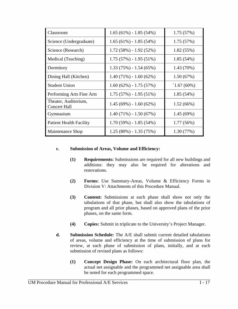
b. Building Efficiency Factors (Guidelines): The following criteria; for building efficiency factors has been adopted from the DGS Procedure Manual for Professional Services, July, 2003 Edition:
Building Type Efficiency Factor Range Mid-Point
Administration / Office 1.67 (60%) - 1.82 (55%) 1.74 (57%)
Library 1.52 (66%) - 1.67 (60%) 1.60 (62%)
______________________________________________________________________________ UM Procedure Manual for Professional A/E Services I - 17
Classroom 1.65 (61%) - 1.85 (54%) 1.75 (57%)
Science (Undergraduate) 1.65 (61%) - 1.85 (54%) 1.75 (57%)
Science (Research) 1.72 (58%) - 1.92 (52%) 1.82 (55%)
Medical (Teaching) 1.75 (57%) - 1.95 (51%) 1.85 (54%)
Dormitory 1.33 (75%) - 1.54 (65%) 1.43 (70%)
Dining Hall (Kitchen) 1.40 (71%) - 1.60 (62%) 1.50 (67%)
Student Union 1.60 (62%) - 1.75 (57%) `1.67 (60%)
Performing Arts Fine Arts 1.75 (57%) - 1.95 (51%) 1.85 (54%)
Theater, Auditorium, Concert Hall
1.45 (69%) - 1.60 (62%) 1.52 (66%)
Gymnasium 1.40 (71%) - 1.50 (67%) 1.45 (69%)
Patient Health Facility 1.70 (59%) - 1.85 (54%) 1.77 (56%)
Maintenance Shop 1.25 (80%) - 1.35 (75%) 1.30 (77%)
c. Submission of Areas, Volume and Efficiency: (1) Requirements: Submissions are required for all new buildings and
additions: they may also be required for alterations and renovations.
(2) Forms: Use Summary-Areas, Volume & Efficiency Forms in
Division V: Attachments of this Procedure Manual.
(3) Content: Submissions at each phase shall show not only the tabulations of that phase, but shall also show the tabulations of program and all prior phases, based on approved plans of the prior phases, on the same form.
(4) Copies: Submit in triplicate to the University’s Project Manager.
d. Submission Schedule: The A/E shall submit current detailed tabulations
of areas, volume and efficiency at the time of submission of plans for review, at each phase of submission of plans, initially, and at each submission of revised plans as follows:
(1) Concept Design Phase: On each architectural floor plan, the
actual net assignable and the programmed net assignable area shall be noted for each programmed space.

______________________________________________________________________________ UM Procedure Manual for Professional A/E Services I - 18
(2) Schematic Design Phase: On each architectural floor plan, the
actual net assignable and the programmed net assignable area shall be noted for each programmed space.
(3) Design Development Phase: On each architectural floor plan, the
actual net assignable and the programmed net assignable area shall be noted for each programmed space.
(4) Construction Document Phases (50%, 95% and100%): On
each architectural floor plan, the actual net assignable and the programmed net assignable area shall be noted for each programmed space.
(5) Other: As requested.
15. SUB-SURFACE EXPLORATION AND EVALUATION:
15.1. Requirements: The A/E shall plan and perform the subsurface exploration and
evaluation and procure the information relative to the site and subsurface conditions relevant to the project requirements. The data procured shall be adequate, correct and reasonably complete for the intended purposes of planning, design, quantity, and cost estimating, and determining the construction feasibility of the project.
15.2. Subsurface Data: The A/E shall make available the procured data relating to the
site and subsurface information and evaluation to the University Project Manager prior to starting their functions of design, review, bidding, construction and inspection respectively.
15.3. Geotechnical Engineer: The work of subsurface exploration and evaluation shall
be performed under the direct guidance, direction, and control of the geotechnical engineer. All submittals to the University relating to and including the results of the subsurface exploration, evaluation and recommendations shall bear the seal of the geotechnical engineer.
15.4. Exploratory Program: During the Schematic Design Phase, the A/E shall submit
to the University Project Manager, for review and approval, three (3) copies of the proposed Exploratory Program. The Exploratory Program shall include, but not be limited to the following:
a. Scope: Understanding of the project and design considerations.
b. Boring Plan: A layout of test borings/pits with reference to existing
physical features and proposed locations of structures. Site plan of the

______________________________________________________________________________ UM Procedure Manual for Professional A/E Services I - 19
project showing location of structures, grading, stormwater management areas, and utilities may preferably be used to show the test locations.
c. Description: Number, type, and estimated depths of test borings/pits or
other investigative systems.
d. Estimated Quantities: Estimated linear feet of earth borings and rock coring and types and estimated quantities of laboratory and field tests.
e. Estimated Cost: Estimated cost for the subsurface exploration at the
billing unit prices.
15.5. Utility Verification: After approval of the Exploratory Program by the UM Project Manager, the A/E shall conduct the subsurface investigation and evaluation. Prior to starting field operations, A/E shall verify the presence and location of underground utilities with Miss Utility, Private Utility Locators, or University Utility Locators if applicable.
15.6. Geotechnical Report: Upon completion of subsurface exploration and evaluation, the A/E shall submit to the University Project Manager three (3) copies of the Geotechnical Report and any additional results, reports, supplements, revisions, modifications or clarifications developed subsequent to the original report. As a minimum, the report shall address each of the following:
a. Geology: Geology and general nature of soil/rock/drainage/ and
groundwater conditions in the project area.
b. History: A history of the project site and relevant information relating to the nearby foundations and structures, underground springs, etc.
c. Boring plan: Boring plan, to scale, indicating boring and test pit locations
referenced to existing physical features and proposed locations of structures and other facilities.
d. Logs: Boring and test pit logs, with soil/ rock description, classification,
and depth of character of fill, ground water observations made during the exploration.
e. Characteristics: Information relating to rock/soil character, consistency,
compressibility, shear strength, safe bearing value, chemical content, corrosiveness, frost penetration depth, permeability, and relevant properties.

______________________________________________________________________________ UM Procedure Manual for Professional A/E Services I - 20
f. Quantity Estimates: depths, locations, and quantity estimates of topsoil, unsuitable soils, existing fill, rock excavations, borrow, demolition debris or controlled substances, etc.
g. Rock Line: Rock line elevations with cross-sectional profiles, evidence
that rock strata is sound and not underlain by mine cavities or lenses that would affect the stability and support capability. Provide recommendation's for corrections in case of questionable stability.
h. Foundation Analyses: Foundation analyses and recommendations
including the presentation of risk and cost effectiveness considerations.
i. Foundation Information: All relevant foundation information including design parameters, elevations of bottom of footings or pile tips, related soil bearing or pile capacity, factors of safety and settlement analysis considerations.
j. Recommendations: Recommendations for design and support of floor
slab, retaining or basement walls, water or damp proofing and drainage, underground utilities, pavements or driveways and parking lots, stability of slopes, ground water seepage control, or other stabilization procedures.
k. Site Evaluation: Relating to the excavation and earthwork feasibility. If
rock excavation is involved, indicate definition, removal and handling type of equipment, blasting requirements, etc. For earthwork, indicate shrinkage factors, suitability of on/off-site materials, and borrow requirements and source. Include groundwater observations, elevations and recommendations for temporary dewatering during construction and for permanent dewatering during construction. Effects of seasonal variations shall be noted.
l. Potential Problems: Identify problems which may affect the cost of
construction and/or cause delays, and furnish construction precautions and recommendations. Identify inspection, testing and quality control requirements during the construction.
m. Stormwater Management Recommendations: Identify the type of
stormwater management facilities suitable for the site and design parameters to be used by site engineer for systems sizing.
16. SEDIMENT AND EROSION CONTROL, AND STORMWATER
MANAGEMENT:
16.1. Requirements: It is required that review and approval be granted by the Maryland Department of the Environment (MDE), Sediment and Stormwater

______________________________________________________________________________ UM Procedure Manual for Professional A/E Services I - 21
Administration (COMAR 26.17.01 and 26.17.02), for all projects in which existing earth surfaces are disturbed in the execution of the project or which on-site stormwater management is required, to current limitations established by MDE. Should a flooding hazard be present, which cannot be alleviated by natural features, retention measures may be required in the design of controls. The A/E shall be responsible for submitting plans, specifications and computations with the Design Development and Construction Document submittals directly to MDE for review. One copy of the transmittal letter with MDE’s signature acknowledging receipt shall be submitted to the University as part of DD submission to the University Project Manager.
16.2. Program: The A/E shall provide sediment and erosion control, and stormwater
management programs at all design phase submissions. The final stormwater management, sediment and erosion control plan(s) shall address all aspects of the construction phase such as stabilization of temporary stockpiles of topsoil, waste material, etc. in addition to the overall requirements of the Sediment and Stormwater Administration.
16.3. Contract Documents: Contract documents and stormwater management
construction shall be in accordance with the Sediment Control Regulations approved and adopted by the MDE. No changes in these measures as shown in the contract documents may be approved by any person or agency other then MDE. The A/E shall be responsible for revising contract documents for any changes required by MDE.
16.4. Reference Manual: The reference manual controlling specifications for Soil
Erosion and Sediment Control, latest edition can be obtained at: a. Maryland Department of the Environment
1800 Washington Boulevard Baltimore, Maryland 21230
16.5. Certification: Contract drawings submitted to MDE for approval must contain
both Engineer’s and Developer’s Certifications. See Division V: Attachments of this Procedure Manual for the Engineer’s and Developer’s Certification Form.
17. WATER AND SANITARY SYSTEMS:
17.1. Requirements: The A/E shall comply with all the requirements of COMAR Title 09, Department of Licensing & Regulation, Subtitle 20, Board of Commissioners of Practical Plumbing and COMAR Title 26, Department of the Environment, Subtitle 04, Regulation of Water Supply, Sewage Disposal, and Solid Waste.
17.2. State Permits: When the project requires connections to water or sewer in excess
of four hundred (400) linear feet and/or a new storage or treatment facility other

______________________________________________________________________________ UM Procedure Manual for Professional A/E Services I - 22
than septic systems that discharge underground, the A/E shall obtain a Water & Sewage Construction Permit from the Applications and Permits Section, Water Management Administration, Department of the Environment.
17.3. Swimming Pools: Where the project requires a design for a swimming pool,
comply with all requirements of COMAR 10.17.01.
17.4. Water Appropriation: When the project requires the withdrawal of either ground water or surface water, on either a temporary or permanent basis, the A/E shall be responsible for complying with all permitting requirements and shall comply with COMAR 26.17.06, "Water Appropriation or Use".
17.5. Water Discharge: When the project requires the discharge of water, on either a
temporary or permanent basis, the A/E shall be responsible for complying with all necessary permits to satisfy the requirements of the National Pollution Discharge Elimination System (NPDES) established under the Federal Act B in accordance with the provisions and conditions of COMAR 26.08.01 – 26.08.04, "Water Pollution".
17.6. Utility Connections: The A/E shall be responsible for making application to and
obtaining from any and all local city and State regulatory agencies, those approvals necessary to make utility connections to available public, private or municipal water and sewer facilities to serve the site or to construct the necessary on-site sanitary facilities to support the building project in its entirety.
a. Owner Approval: The A/E shall obtain, from the owners of the utilities,
the necessary approvals for connection to the same and shall be responsible for coordination of the actual utility connection with the contractor's work schedule.
b. Trade Permits: Mechanics and/or trade permits will be obtained by those
trades as required by them.
c. Payment: Actual payment of any local water and sewer charges or connection fees will be the responsibility of University unless otherwise required. The A/E shall direct the utility owner to invoice the University for said charges unless otherwise required, and shall copy the University Project Manager on all correspondence and telephone conference reports.
18. PRESENTATION TO THE ARCHITECTURAL REVIEW BOARD (ARB):
18.1. Requirements: The A/E will be required to make presentations to the Board of Architectural Review at the Schematic/ Design Development Phase in connection with new buildings, building additions, and major renovations that alter the building exterior.
______________________________________________________________________________ UM Procedure Manual for Professional A/E Services I - 23
18.2. Schematic Design Presentation:
a. The Presentation: The Board of Architectural Review will consider this
presentation as the Schematic Design Phase regardless of the state of development and shall make its comments and recommendations accordingly.
b. Notification: The A/E will be notified of date and time of the board
meeting. The A/E will be advised of the time limit for the presentation to the board. The University Project Manager will schedule any of the A/E presentations before the Board of Architectural Review. The A/E shall provide an explanation of the program, the schematic design of the building, the site, a simple block model and cost of the project.
c. Considerations: The board will consider all factors affecting the project,
including program, setting, adaptability of the master plan, and the architectural design. The board, in its comments and recommendations, will evaluate the functional and aesthetic aspects of the project design, and consider whether the project can be built economically, consistent with sound construction and minimum maintenance.
d. Recommendations: After considering the submission, the board shall discuss with the A/E the tentative recommendations of the board. The A/E will be given the opportunity to reply to the board's comments. The Board shall develop the final recommendation in the presence of the A/E. The A/E and University will take the ARB comments and recommendations into consideration at the Design Development Phase and respond as necessary. The University will then inform the ARB in writing of the University’s intended design direction.
18.3. Minutes: The Board supplies written minutes which are sent to University.
The University Project Manager will advise the A/E and instruct them as to how they are to proceed.
19. APPROVAL OF CONTRACT DOCUMENTS:
19.1 The approval of contract documents, which includes plans and specifications, by the University in no way relieves the A/E of their responsibility for:
a. The accuracy and completeness of such documents,
b. Compliance with required Standards, Codes, Ordinances or other
applicable regulations, and

______________________________________________________________________________ UM Procedure Manual for Professional A/E Services I - 24
c. Compliance with standard of care governing the A/E performance. 20. CERTIFICATION OF CONTRACT DOCUMENTS:
20.1. Professional Certification: Immediately after the contract documents have been reviewed, approved and all necessary signatures placed thereon, the A/E shall place the following certification on each of two prints of the title signature sheet of the plans and forward same to the University Project Manager: "The contract documents for the indicated public improvement were prepared under my supervision and, to the best of my knowledge, information and belief, they comply with the relevant building codes."
20.2. Seal and Signature: All contract documents, drawings, specifications, etc., shall
bear the seal and signature of the primary A/E and the seal and signature of each consultant to the primary A/E on drawings and specifications within their area of responsibility.
21. PAYMENTS FOR PROFESSIONAL SERVICES:
21.1. Full and/or Partial Contract: When the A/E has a full and/or partial services contract, payment requests shall be made per the A/E contract documents. When the A/E has extra work on a not to exceed basis, payment requests shall be made in accordance with the A/E contract documents.
21.2. Payment Request: Bills may be presented at the beginning of each month
covering the costs of service during the previous month. Furnish original and one copy.
21.3. Required Services: All services required under the A/E agreement must be
provided prior to the University’s approval of each phase as well as prior to the University’s approval of A/E invoices for payment of applicable fees.
21.4. Final Payment: Final payment of the A/E’s Construction Administration Phase
fee shall only be payable upon submission and University acceptance of the “Record Drawings” and all other remaining outstanding documentation or services. Final payment of the A/E’s Post construction Phase fee shall be payable upon submission of the Post Construction report.
END OF DIVISION I
DIVISION II PROCEDURES
UM Procedure Manual for Professional Services II-1
____________________________________________________________________________
DIVISION II
PROCEDURES ______________________________________________________________________________ Latest Update 8-13-14, See underlined text. 1. PRE-DESIGN CONFERENCE:
1.1. Purpose: As soon as practicable after the A/E's contract with the University has been fully executed the University Project Manager will call a conference to initiate the project. This meeting will include the A/E and its consultants, a representative(s) of the client, the University Design Review Team, and the University Project Manager.
1.2. Topics: At this meeting, the following will be furnished, made available, and/or
reviewed with the A/E: a. University Procedure Manual for Professional Services b. University A/E Design Standards c. University CAD Standards included in the University A/E Design
Standards
d. University Project Number
e. Program: The approved Project Program, if one was prepared for the project.
f. Hazardous Materials: Review the statements in the approved Project
Program and/or other information addressing the presence or absence of lead-based paint, asbestos, PCB, and/or other materials that necessitate restricted handling.
g. Project Budget: Review the design-to budget for the project.
h. Project Drawings: Review project drawing distribution.
i. Project Forms: Project Forms for Summary of Areas-Volume-Efficiency,
Tabulation of Gross Area, Summary of Net Assignable Areas, Building Code Study Data, Project Description Sheets with Instructions, Request for Change Order Proposal Form, Engineer’s and Developer’s Certification Form, for all

UM Procedure Manual for Professional Services II-2
types and phases of the project are included in Volume V of this Procedure Manual.
j. University Personnel: The names and titles of the University personnel
involved with the project. k. Available Information: All site, utility, topographic and master plan
information as may be available (if additional information is required, it must be requested in writing by the A/E).
l. Site Visit: Date and authorization for site visit.
m. Permits or other Regulatory/Municipal Requirements: Where required,
applicable Federal, State, or Local permits and/or requirements for MDE, BGE, Trigen, State Fire Marshall, NIH, or Baltimore City and local jurisdictions or other utilities, shall be included in the CD’s.
n. Project Service Schedule: The project service schedule for all applicable
A/E services shall be developed, and shall include the following as a minimum: (1) Programming , Study and Interior Design
a) Capital Project Program - Part I:
1) Meetings with the clients representatives 2) A/E Submission
3) University Review
4) Meetings with A/E
5) Final Submission
b) Capital Project Program - Part II:
1) Meetings with the clients representatives 2) A/E Submission
3) University Review
4) Meetings with A/E
UM Procedure Manual for Professional Services II-3
5) Final Submission
c) Feasibility Study: 1) Meetings with the clients representatives 2) A/E Submission
3) University Review
4) Meetings with A/E
5) Final Submission
d) Space Planning:
1) Meetings with the clients representatives 2) A/E Submission
3) University Review
4) Meetings with A/E
5) Final Submission
e) Engineering Study:
1) Meetings with the clients representatives 2) A/E Submission
3) University Review
4) Meetings with A/E
5) Final Submission
f) Interior Design:
1) Meetings with the clients representatives 2) A/E Submission
3) University Review

UM Procedure Manual for Professional Services II-4
4) Meetings with A/E
5) Final Submission
(2) Design Phase Services:
a) Concept Design Phase: Included when required by the
Request for Proposal (RFP).
1) Program Verification Phase and Meetings 2) A/E Submission
3) University Review
4) Design Meetings with A/E
5) Meetings with A/E and other parties to review cost
estimate, and conduct Value Engineering sessions as needed.
b) Schematic Design Phase:
1) Program Verification Phase and Meetings. When the
RFP requires a Concept Design Phase, the Program Verification shall be included in that phase.
2) A/E Submission
3) University Review
4) Design Review Meetings with A/E
5) Meetings with A/E and other parties to review cost
estimate, and conduct Value Engineering sessions as needed.
c) Design Development Phase:
1) A/E Submission
2) University Review
3) Design Review Meetings with A/E

UM Procedure Manual for Professional Services II-5
4) Meetings with A/E and other parties to review cost
estimate, and conduct Value Engineering sessions as needed.
d) Construction Documents Phase: 50% CD, 95% CD, &
100% CD:
1) A/E Submission
2) University Review
3) Design Review Meetings with A/E
4) Meetings with A/E and other parties to review cost estimate, and conduct Value Engineering sessions as needed.
(3) Bid Support and Construction Administration Services:
a) Bidding Support
b) Construction Administration Services
c) Post Construction Survey
o. Additional Information: Determine any additional information which the A/E may need to complete the project.
p. Special Policies: Any special University policies applicable to each phase of
the project.
q. University Design Standards: See the Design Standards for the applicable University.
r. Available Data: In new construction and renovation, alteration and addition projects, such data as may be available on the existing facilities will be identified to the A/E. The A/E will be given access to the University Archives for the purpose of identifying and reviewing available documentation. The University will make arrangements to have the identified documents printed (1 set) for the A/E’s use. The A/E must visit the site of the project and familiarize themselves fully with the use, operational conditions, and limitations of said site and perform sufficient field survey or obtain measurements and other information relative to existing conditions and improvements as provided in the project program.
UM Procedure Manual for Professional Services II-6
s. Project Design Review Meetings: During the preparation of each Design
Phase a series of design review meetings will be held with the University Project Manager, University Design Review Team, and the designated person(s) representing the users. At the completion of each Design Phase a Review Conference for each Design Phase will be coordinated by the University Project Manager to review the progress of the project and provide comments to the A/E Design Team. Meetings will be scheduled at the conclusion of each design phase and as needed. The A/E shall prepare and distribute minutes of these meetings to the University Project Manager.
t. Cost Estimates:
(1) Budget Cost Estimates: Provide a budget cost estimate for all
programs, studies, and space planning reports as required by the A/E scope of work.
(2) Construction Cost Estimates: A construction cost estimate shall be
fully developed for each design phase. Total project cost figures shall include the costs escalated up to the anticipated midpoint of construction. The A/E shall not design for, or contemplate, funds being available in excess of those identified as the design-to budget by the University.
u. UM Web Site: UM Master Specifications, A/E Design Standards Manual,
A/E Procedures Manual, CAD Standard Drawing Templates, CAD Detail Files and Project Forms can be accessed at the following site: http://www.umbfm.umaryland.edu/
2. GENERAL DESIGN DOCUMENT REQUIREMENTS:
2.1. Prime Consultant (PC): The prime consultant shall be responsible for all aspects of the designs produced by the prime consultant and sub-consultants including but not limited to the verification and accuracy of all floor plans either created by the PC or supplied by the University. When electronic files of existing buildings are supplied by the University for use by the design team, the PC shall be responsible for verifying, and when necessary correcting, the plans to ensure they are correct. Plans that are inaccurate will not be acceptable to the University. The prime consultant shall be responsible for coordination between disciplines during all phases of the design process. Coordination issues documented as part of a review shall be addressed by the affected disciplines and the appropriate corrections shall be documented on the next submission. The PC shall also be responsible for the preparation of the Division 1 specification sections.
UM Procedure Manual for Professional Services II-7
2.2. Sign and Seal Drawings: Each consultant shall sign and seal a complete set of 100% bid documents for their discipline. The signed and sealed drawings shall be transmitted electronically, as pdf files, to the University unless otherwise directed by the University Project Manager.
2.3. Number of Submission Sets: The following requirements apply to all design
documents for all projects unless waived by the University in writing.
a. The complete set of design documents that are submitted to the University for the SD, DD, 50%, 95% and 100% CD review’s shall include twelve (12) sets of bound specifications, eight (8) full size sets of drawings and four (4) mini (half size) sets of drawings to the University for their use and distribution. For additional documentation submission requirements see paragraph 3.1.
b. Some projects may require additional sets for review. The A/E shall verify
the required number of sets with the University Project Manager, prior to submission of the above stated minimum.
c. CAD Drawings and Files: Provide one (1) complete set of electronic files
(CAD) for the 50% submission, the 100% bid document submission, conformance sets as necessary during bidding and construction for incorporation of all addenda and drawing changes, and the “Record Drawing” submission. See University Architectural and Engineering Design Standards for the applicable campus latest edition, for the University’s Guidelines for CAD electronic file requirements.
d. General Electronic Files: General electronic files include scopes of work,
project specifications, cost estimates, studies, A/E calculations, building and/or system analysis, VE documentation, produced by the A/E team. Provide one (1) complete set of general electronic files along with the “Record Drawing” submission. See University Architectural and Engineering Design Standards for the applicable campus latest edition for the University’s Guidelines for CAD electronic file requirements.
2.4. General Drawing Organization Requirements:
a. CAD Drawings: A/E's shall produce contract documents on CAD
(Computer-Aided Design). b. Drawing Material: The signed and sealed 100% bid documents will be
accepted electronically as pdf files. The “Record Drawings” will be accepted electronically in dwg and BIM formats. For all interim contract drawing submissions, for review, paper media will be acceptable.

UM Procedure Manual for Professional Services II-8
c. Drawing Templates (Sheet Sizes): Some University Campuses require the
A/E to use Standard Drawing Templates for all projects. Standard Drawing Templates include 8 1/2 x 11, 11 x 17, 24 x 18, 24 x 36, 30 x 42, and 30 x 48 Drawing Templates. The 8 1/2 x 11 and the 11 x 17 sheet templates shall only be used by the A/E to document revisions and/or additions to the bid documents when full size revision sheets are not required to document the changes otherwise full size sheets shall be used to document all revisions to the bid documents.
d. Dates/Project No.: Dates must be shown on all drawings, with revision
dates when applicable. University Project number, building number, and title shall be shown in the bottom right hand corner and scale shall be noted.
e. Drawing Scales: Floor Plans and Elevations and Sections should be developed using a Scale of 1/8 inch = 1 foot -0 inches. Use a Scale of 1/4 inch = 1 foot-0 inches for partial floor plans such as toilet rooms, class rooms, mechanical equipment rooms, electrical equipment rooms, and other partial floor plans used for selected projects, etc.
f. Graphic Scales: Each drawing containing plans, details, sections, and
elevations shall include a graphic scale(s) located in the lower right hand area of the drawing. Where drawings include details and or sections at various scales, provide a graphic scale for each scale used.
g. Key Plan: Each drawing containing partial plans of floor or roof areas shall
include a key plan which indicates the relationship of the partial plan to the complete floor plan.
h. Architectural and Engineering Data: The following architectural and
engineering data shall be included on the appropriate drawing for each architectural, structural, mechanical and electrical set as defined in the UM Standard Drawing Numbers and Sheet Titles in Division V: Attachments of this Procedure Manual.
(1) Architectural:
a) Under the heading of code analysis list data for all applicable
codes, federal accessibility standards, building use/ construction classifications, fire resistance ratings for major building components, all protected vertical openings, all unprotected vertical openings, fire protection systems, maximum travel distances and dead end corridors with automatic sprinklers, exit and exit access widths for sprinklered buildings, special locking arrangements (if

UM Procedure Manual for Professional Services II-9
applicable), roof access, elevators, smoke detection, and means of egress. Include with each major heading all applicable code references and COMAR References. Also include the project gross area in square feet and the net assignable area in net square feet.
(2) Structural:
a) Design dead load, partition load and live load for each and
every area of the building, including the roof, and snow loads for the roof areas. Allowances shall be included, wherever applicable, for additional loads due to mechanical equipment, piping, ceilings, etc.
b) Design bearing value for all spread footings and caissons, and
bearing load for all piles. c) Concrete strength required for each part of the building.
d) Steel yield point strength for all reinforcing and structural
steel.
(3) Mechanical:
a) Heating: Total heat loss for the building in BTUs and steam
pounds per hour for steam heating source, ventilation load in BTUs, domestic hot water load in BTUs, heating design temperatures inside and outside, and building gas consumption in cubic feet per hour.
b) Cooling: Total heat gain for building in BTUs per hour,
ventilation load for building in BTUs per hour, indoor/outdoor temperature and humidity design conditions.
c) Plumbing: Total plumbing fixture unit counts for sanitary,
domestic cold water, domestic hot water and domestic hot water consumption maximum demand in gph, maximum gas consumption in cubic feet per hour for laboratory use.
(4) Electrical:
a) Electrical: Estimated load summary of the demand and
connected electrical load for the normal power distribution system, including breakdown of the lighting system,

UM Procedure Manual for Professional Services II-10
receptacles, HVAC systems, etc. Estimated load summary of the demand and connected electrical load for the emergency power distribution system, including breakdown of the loads for the emergency system, legally required standby system, and optional standby system, as well as the type and size of stand-by power unit(s) and its source.
b) Special Systems: (as appropriate) System description and
features for all special systems, including telecommunications, security, fire alarm, metering, audio visual, and CCTV.
2.5. Cover Sheets: The A/E shall use the University standard cover sheet provided by
the University for all Projects for the UM campus. When preparing documents for other campuses the A/E shall follow the Drawing Standards for that campus or create a cover sheet. The following items shall be included on the cover sheet: a. University Logo b. Name of Project c. University Project Number d. A/E Project Numbers e. Location (full address as directed by the University) f. Board of Public Works-Governor, Comptroller, Treasurer g. Maryland General Assembly-Senate President, House Speaker h. Names, addresses and phone numbers of all consulting firms i. Sheet Index: The A/E shall use the University Standard Sheet Numbers and
Sheet Titles for all projects See Division V: Attachments of this Procedure Manual for further information.
2.6. Title Block Information and Format: The A/E shall use the UM standard sheet
template files, provided by the University, for all Projects for the UM Campus. When preparing documents for other campuses the A/E shall follow the drawing standards for that campus or use their own drawing standards. The following items shall be included in the UM Title Block: a. A/E Consultant Block: List each consultant, including title, address,
telephone, and fax numbers.

UM Procedure Manual for Professional Services II-11
b. Registration/Stamp Block: Architects' and engineers' names, seals, etc.
shall be placed in this location on each drawing.
c. Project Title Block: Include the University project number, A/E project number, the University CAD file number, and date in the appropriate locations in this block. The University will furnish the required CAD File Number to the A/E.
d. Sheet Title Block: Such as "FIRST FLOOR PLAN", "FINISH
SCHEDULE," etc.
e. Revision Block: List each revision for each drawing indicating revision number, date of revision and brief description.
f. Sheet Number Block: Sheet numbers shall be comprised of a discipline specific letter prefix followed by a three digit number without being separated by spaces, periods, or dashes. The three digit numbers shall start at 001 for each discipline. Divide the sheets into groups according to disciplines and use the following letter prefix for each: A for architectural; C for civil/site; L for landscaping; S for structural; M for mechanical; and E for electrical. When demolition drawings are required divide the sheets into groups according to disciplines and use the following letter prefix for each: AD for architectural demolition; CD for civil/site demolition; LD for landscaping demolition; SD for structural demolition; MD for mechanical demolition; and ED for electrical demolition. If a project requires drawings of specialty areas e.g data/communication, security, audio/visual, or food service, a prefix for sheet numbering shall be recommended to the University Project Manager for approval. For a complete list of standard project sheet titles and sheet numbers, for UM campus projects, see Division V: Attachments of this Procedure Manual.
g. Location of the Project: As for example: “University of Maryland
Baltimore”, “Coppin State University”, “Towson University”, “University of Baltimore”, “University of Maryland, Baltimore County”.
h. Drawing Scale: e.g. As noted, 1/8 inches = 1foot - 0 inch etc.
2.7. Site Plans: Use 1 inch = 40 feet, unless due to unusual circumstances another scale
is specifically authorized in writing by the University Project Manager. The limit of the work must be accurately identified and located. Architectural scales may not be used.

UM Procedure Manual for Professional Services II-12
a. Plans shall include locations of all new and existing buildings and structures, roads, walks, utilities, flood plains, wetlands and critical areas, etc. It shall indicate existing and proposed contours. Where a master plan exists, the plan shall show the future buildings adjacent to the proposed project.
b. A complete sediment control and stormwater management plan(s) as required
by MDE, including Engineer's Certification and University of Maryland Certification shall be prepared and submitted to the University as required in Division I of this Procedure Manual.
c. Plans and specifications for excavation, retaining structures, dewatering, etc.,
where required, shall be included in the contract documents.
2.8. AutoCAD Protocol and Standards: The AutoCAD protocols and standards required by the University are defined in the campus Architectural and Engineering Design Standards, latest edition. In addition, the current trend in construction documentation is to model projects using Building Information Modeling (BIM) systems. All future projects shall be modeled using BIM processes, including the use of Revit software for architectural and structural disciplines and auto cad MEP for MEP disciplines. Each campus will develop standards and protocols for using BIM and will amend the appropriate University campus design standards to include those requirements as they are finalized and adopted.
2.9. Floor Plans: Floor plans shall be double line. Overall dimensions shall be shown.
Major rooms, areas or space shall be appropriately identified by name, actual net square footage, and programmatic, net square footage. Each floor plan shall contain a note below the plan, indicating the approximate gross square feet and the net assignable square feet for each floor, including basements, mechanical floors, penthouses, etc. The first floor plan in the case of multiple story buildings shall contain a summary for the entire building.
a. Demolition Plans: Where demolition work is required, the floor plans and/
or site plan shall clearly show what work is to be removed and a reference provided to identify the proposed work for the same area. If lead is identified, the demolition plan and related notes shall describe the location and refer to the specification section which shall specifically describe or give the necessary regulation for the removal and disposal of potential lead hazards.
b. Lettering Size: Shall be a minimum one eighth (1/8) inch high.
c. Line Work: All line work shall be of sufficient density to provide uniform
reproduction and photographic quality. See the CAD standards in the University Design Standards for additional information.

UM Procedure Manual for Professional Services II-13
d. Column Grids: Provide column lines and numbers, and use north arrow
indications on floor plans, part plans, sections, elevations, details, mechanical /electrical system riser diagrams etc.
e. Section and Detail Symbols: Note the sheet location of the section or detail
involved.
f. Key Plan: Where a portion of a plan appears on a sheet, provide a key plan that shows the location of that portion with respect to the other portions.
g. Room Title and Number: Show room title and number on all plans.
Coordinate with the University; for the final room number and name assignments.
h. Delineation of Work: Carefully delineate all drawings to distinguish
between new work, existing work to remain, and demolition work. i. Partial Plans: Provide larger scale partial plan(s) for project areas such as
assembly halls, toilet rooms, mechanical equipment rooms, electrical equipment rooms etc.
2.10. Elevations: The design of the elevations shall define materials, coordination between
materials and systems, and their placement. There shall be an elevation drawn for each building facade. The scale of the elevations shall not be less than one eighth (1/8) inches = 1 foot- 0 inch.
2.11. Sections:
a. Provide appropriate building sections necessary to show all sectional profiles of the building. There shall be at least two (2) building sections taken perpendicular to each other through the main body of the building.
b. Provide detailed sections through all major architectural elements including
walls, stairs, elevators, atria, skylights, auditoria etc.
2.12. Details: Details shall be at a large enough scale to illustrate all structural elements, construction materials, dimensions etc.
2.13. Reflected Ceiling Plans: Reflected ceiling plans are intended to coordinate the
design intention of the various trades involved, and should clearly indicate the locations of all types of ceiling materials, bulkheads, full height partitions, access doors, diffusers, grilles, sprinkler heads, lights, speakers and all other work.

UM Procedure Manual for Professional Services II-14
2.14. Future Expansion: Indicate proposed future expansions (both vertical and horizontal) and planned future equipment shown as dotted lines on site plans, architectural floor plans, engineering floor plans, roof plans and in elevations and sections.
2.15. Specifications:
a. UM Master Specifications: Some University Campus’s require the A/E to use their Master Specifications for their projects. UM has developed a complete set of Master Specifications for Divisions 1, 14, 15, and 16. These sections shall be used for all UM Projects. The A/E shall review the University’s Master Specification Table of Contents, provided by the University, and request from the University Project Manager all appropriate specification sections necessary to suit the current project scope. The A/E shall edit the University Master Specification Sections as indicated in the Design Standards. All project specification sections for each discipline shall include the standard UM header and footer and the body and footer shall use Times New Roman, size 12 text.
b. A/E Specifications: The A/E shall utilize their own specifications and/or
other resources only in those cases where the University Master Specification does not include the required equipment, materials, or construction procedures to suit the current project.
c. Specification Cover Sheet: See Division V: Attachments of this Procedure
Manual for the University’s standard cover sheet. The color of the cover page shall be selected by the University.
d. Table of Contents: All pages shall be complete, listing all division numbers
and division titles as shown by CSI. After each division number and title, indicate the page numbers where the specification is to be found. If the project does not include any work in a specific division show "none" in the column of page numbers.
e. Assembly of Specifications: All specification pages must be firmly and
permanently bound together with binding tape to prevent the removal of a page without the possibility of detection. Specifications must be printed on both sides of paper.
f. A/E shall follow the University Master Specification numbering and three
part section format.
g. Where trade names or proprietary items are identified reference shall be made to "or approved equal".

UM Procedure Manual for Professional Services II-15
h. Whenever brand name products are included at least three acceptable brands shall be named, if possible.
i. Hardware schedules are required in the specification. Hardware schedules shall be open to full competition except where proprietary cylinders or other hardware elements are required by the University. The A/E shall determine the requirements of the University for the master key system and special hardware requirements.
j. Generalized all-inclusive ("grandfather") clauses must be avoided. Be
specific with all written directions, instructions, and requirements. Specifications should follow CSI recommended practice and be clear, complete, correct, concise and coordinated.
k. Reference shall be made to the General Conditions in the appropriate
divisions of the specifications.
l. Instructions to Bidders: Intentionally omitted. This is the responsibility of either the University or the Construction Manager.
3. SPECIFIC PROGRAMMING AND STUDY SERVICE REQUIREMENTS:
3.1. General: All documentation shall utilize the University Standard Cover Sheets and
Drawing Templates for drawings and bound reports. 3.2. Capital Project Program - Part I: The A/E shall complete the Capital Project
Program - Part I consistent with the terms of the A/E contract and shall include, as a minimum, the information indicated in the following paragraphs: a. Preface: Include a campus map identifying the project site.
b. Introduction: Include description of the vision for the project.
c. Project Overview: Include a description of the University Campus. A
summary of the project and a table which indicates the existing campus NASF by room code.
d. Project Justification: Include a description of the existing conditions.
Identify projected figures for student enrollment, faculty and staff for both fulltime and part time populations over six (6) to sixteen (16) year time span. Provide a summary of problems to be addressed by the project and their consequences potential alternatives and a preferred solution for the project.
e. Project Scope: Include a description of the project site and the proposed
construction.

UM Procedure Manual for Professional Services II-16
f. Meetings: The consultants shall attend meetings with University personnel
representing the client, facilities management, public safety, etc. to review the requirements for the project and the project documents submitted in this phase.
g. Responses: Consultants shall respond to review comments made by UM
representatives.
h. Submission: The A/E shall provide at least two (2) bound documents to the University.
3.3. Capital Project Program - Part II: The A/E shall complete the Capital Project
Program - Part II consistent with the terms of the A/E contract and shall include, as a minimum, the information indicated in the following paragraphs:
a. Instruction to the A/E: Include a summary of the project, A/E
qualifications, and a hazardous material statement.
b. Design Services: Include a general scope of work, identify basic design services, describe supplemental design services and supporting expert studies applicable to the project, summarize the drawing and document formats, and identify the information provided by the University.
c. Design Criteria: Summarize the requirements for codes, design standards,
site development, architectural and structural designs, mechanical and electrical designs, and identify the building operation and maintenance requirements.
d. Room Specifications: Summarize the building service requirements, and
room specification sheets. Also include a stacking diagram and a proposed program summary. Also include space layouts for typical laboratory module and/or other specialized rooms, complete with all appropriate dimensions, locations of furniture, case work, and equipment.
e. Appendix: Include a Building Code List, Project Consistency Report and an
Environmental Assessment Form.
f. Meetings: The consultants shall attend meetings with University personnel representing the client, facilities management, public safety, etc. to review the requirements for the project and the project documents submitted in this phase
g. Responses: Consultants shall respond to review comments made by UM representatives.

UM Procedure Manual for Professional Services II-17
h. Submission: The A/E shall provide at least two (2) bound documents to the
University.
3.4. Feasibility Study: The A/E shall complete the Feasibility Study consistent with the terms of the A/E contract and shall include, as a minimum, the information indicated in the following paragraphs:
a. Introduction: Include an introduction to the project and what the university
expects to accomplish.
b. Executive Summary: Include a summary of the requirements for a new project, a renovation project, an addition to an existing building or a replacement of an existing building.
c. Existing Conditions: For new construction summarize the location and
condition of the project site including the utilities. For renovation projects, addition to a building, or a replacement building summarize the conditions of the building including the architectural, structural, mechanical, electrical, plumbing, and safety elements.
d. Analysis: For new construction include a detailed analysis for each
discipline. For renovation projects or an addition to a building include a detailed analysis of the existing systems and the anticipated modifications to each system.
e. Recommendations: When more than one design option is included in the
study include the consultant’s recommendation for each design option.
f. Cost Estimate: Include a summary of the cost estimate for the base design and any alternate designs.
g. Appendix: Include a detailed cost estimate spread sheet identifying the
material and labor cost by units. Also include any drawings on 11x17 sheets to support the study.
h. Meetings: The consultants shall attend meetings with University personnel
representing the client, facilities management, public safety, etc. to review the requirements for the project and the project documents submitted in this phase.
i. Responses: Consultants shall respond to review comments made by UM representatives.

UM Procedure Manual for Professional Services II-18
j. Submission: The A/E shall provide at least two (2) bound documents to the University.
3.5. Space Planning: The A/E shall complete the Space Planning consistent with the
terms of the A/E contract and shall include, as a minimum, the information indicated in the following paragraphs: a. Introduction: Include an introduction to the project and what the university
expects to accomplish.
b. Executive Summary:
c. Existing Conditions: Identify existing conditions and how they may affect the project.
d. Analysis: Include the following:
(1) Program Verification: This service shall include a program
verification element. The consultants shall attend meetings with University personnel representing the client, facilities management, public safety, etc. to review the requirements for the project.
e. Recommendations: Include the following:
(1) Planning Concepts: The consultants shall provide at least three (3)
space planning concepts for the area, complete with all appropriate dimensions, locations of case work, furniture, and equipment.
f. Cost Estimate: Include a budget cost estimate for each space planning
concept.
g. Appendix: Include the following:
h. Responses: Consultants shall respond to review comments made by UM representatives.
i. Submission: The A/E shall provide at least two (2) bound documents to the
University. 3.6. Engineering Study: The A/E shall complete the Engineering Study consistent with
the terms of the A/E contract and shall include, as a minimum, the information indicated in the following paragraphs:
a. Introduction: Include an introduction to the study and what the university
expects to accomplish.

UM Procedure Manual for Professional Services II-19
b. Executive Summary: Include a summary of the requirements for a new
project, a renovation project, an addition to an existing building or a replacement of an existing building.
c. Existing Conditions: For new construction summarize the location and
condition of the project site including the utilities. For renovation projects, addition to a building, or a replacement building summarize the conditions of the building including the architectural, structural, mechanical, electrical, plumbing, and safety elements.
d. Analysis: For new construction include a detailed analysis for each
discipline. For renovation projects or an addition to a building include a detailed analysis of the existing systems and the anticipated modifications to each system.
e. Recommendations: Include a summary of the proposed new systems and/or
equipment in a base design and any recommended alternate designs.
f. Cost Estimate: The consultants shall submit a Budget Cost Estimate for this study.
g. Appendix: Include Life Cycle Cost Analysis Calculations supporting the
systems and or equipment recommendations.
j. Meetings: The consultants shall attend meetings with University personnel representing the client, facilities management, public safety, etc. to review the requirements for the project and the project documents submitted in this phase.
k. Responses: Consultants shall respond to review comments made by UM representatives.
3.7. Interior Design: The Architect/Interior Designer shall complete the Interior Design
consistent with the terms of the A/E contract and shall include, as a minimum, the information indicated in the following paragraphs:
a. Finished Materials: Include at least two (2) material samples for finishes
such as carpet, ceiling tile, wall tile, floor tile, window blinds, fabric for furniture, window drapes and wood panels.
b. Color Boards: Include a color board with at least two (2) color samples for each finish.
UM Procedure Manual for Professional Services II-20
c. Cost Estimate: The consultants shall submit a Budget Cost Estimate for the interior design.
d. Meetings: The consultants shall attend meetings with University personnel
representing the client, facilities management, public safety, etc. to review the requirements for the project and the project documents submitted in this phase.
e. Responses: Consultants shall respond to review comments made by UM representatives.
4. DESIGN PHASE AND SUBMISSION REQUIREMENTS:
4.1. General: The submission requirements identified below and in the following
paragraphs represent the minimum requirements the University expects from each discipline for each specific submission unless waived by the University Project Manager in writing.
a. Transmittal: Transmittal letter with each submission package.
b. MDE Transmittal: Copy of transmittal letter to MDE indicating that the
project has been submitted for MDE review where required for projects.
c. Cost Estimate: Provide a complete cost estimate identifying the anticipated cost, for each discipline, for each submission phase as required by the A/E Contract.
d. Tabulations: Update and submit Tabulations of Areas-Volume-Efficiency
in triplicate at each submission phase.
e. Design Data Form: Building Code Design Data form.
f. Geotechnical Report: Complete Geotechnical Report.
g. Response to Comments: Provide a written response to the University review comments from the previous design submission, addressing each review comment individually.
h. Completed LEEDTM check list.
4.2. Concept Design Phase: When required by the University, the A/E shall complete
the Concept Design Phase of the project consistent with the terms of the A/E contract and shall include the submissions indicated in the following paragraphs:
UM Procedure Manual for Professional Services II-21
a. Documentation: All documentation shall utilize the University Standard Cover Sheets and Drawing Templates for drawings and bound reports.
b. Architectural Submission: The architectural submission shall include the following drawings and/or bound reports:
(1) Program Verification Phase: Include a Program Verification Phase.
See Schematic Design Phase for requirements.
(2) Drawings: The drawings shall include the following:
a) Site Development Plan: A site plan at a scale of 1 inch = 50 feet-0 inches shall include the major proposed features such as sidewalks, roadways, parking areas, loading docks, site amenities such as benches, planting beds, trash receptacles, stairs in outdoor spaces, existing and new grading, contractor’s staging area, and the limits of contract line. Provide elevations to show the relationship of major elements in the vertical plane as necessary with appropriate drawing notations. Also include a key plan identifying the site’s relationship to the campus.
b) Building Plans, Elevations and Section’s: Building plans,
elevations and sections at a scale of 1/8 inch = 1 foot-0 inches shall include the following:
1) Floor Plans shall indicate the functional relationship
of major spaces with appropriate drawing notations.
2) Elevations shall indicate massing of materials and fenestration with appropriate drawing notations.
3) Sections shall indicate the vertical relationship to
grade and adjacent buildings, the floor to floor heights and major elements in the building or located on the roof with appropriate drawing notations.
4) The plans, elevations, and sections can be developed
as a model, a perspective, or a computer generated slide presentation to walk through the building.
(3) Bound Reports: Bound Reports shall include the following:
a) A brief description of the proposed design concepts.

UM Procedure Manual for Professional Services II-22
b) A brief description of energy conservation features.
c) An Area Analysis identifying the total net area and total gross area for the Program, the Design, and the Deviation between the program and the design for the Net Gross Area.
c. Structural Submission:
(1) Bound Reports: Bound Reports shall include the following:
a) A brief description of the proposed design concept.
b) A brief description of the structural system including the
foundation. Provide a minimum of two (2) design approaches.
d. Mechanical Submission:
(1) Drawings: A site plan at a scale of 1 inch = 50 feet-0 inches shall include the locations of existing major mechanical utility systems, and locations of new connections.
(2) Bound Reports: Bound Reports shall include the following:
a) A brief description of the each engineered system, such as
HVAC, Plumbing, Fire Protection, and or other systems as required by the program. Provide a minimum of two (2) design approaches for HVAC and Fire Protection Systems and include Green Design Features where applicable.
b) A brief description of energy conservation features.
e. Electrical Submission:
(1) Drawings: A site plan at a scale of 1 inch = 50 feet-0 inches shall
include the locations of existing major electric and communication utility systems, and locations of new connections.
(2) Bound Reports: Bound Reports shall include the following:
a) A brief description of the each engineered system such as
Lighting, Power Distribution, Security, Fire Alarm, Audio/Visual, Telecommunication and or other systems as required by the program.
b) A brief description of energy conservation features.

UM Procedure Manual for Professional Services II-23
f. Consultants shall respond to review comments made by UM representatives.
4.3. Schematic Design Phase: The A/E shall complete the Schematic Design Phase of the Project consistent with the terms of the A/E contract and shall include the submissions indicated in the following paragraphs.
a. Program Verification Phase: The A/E, and appropriate consultants, will
attend program verification meetings with University Representatives to review the program requirements. The University representatives will include the University Project Manager, the University design team, and the client representatives. When the University requires a Concept Design Phase, the Program Verification shall be included in that phase.
(1) The A/E shall provide a tabulation document which represents the
Tabulations of Areas - Volume - Efficiency. This document shall be submitted as an electronic file in either a “doc” file format or in an “xls” spread sheet file format.
(2) Provide appropriate bubble diagrams and stacking diagrams to
represent the intended horizontal and vertical adjacencies. (3) The design process shall not proceed to the next design phase until
the Program Verification Phase has been reconciled and approved by UM.
b. Civil SD Submission:
(1) Site Plan shall show locations of existing buildings and structures,
roads, walks, utilities, flood plains, wetlands and critical areas within two hundred (200) feet of the proposed structure and/or within the limits of the contract. It shall indicate proposed site improvements, grading, access, parking areas, utilities, etc. Where a master plan exists, the site plan shall show the future buildings adjacent to the proposed project, proposed structures, and/or within the limit of contract, grading, drainage, planting, lighting, access, sediment and erosion control and storm water management conceptual drawings.
(2) Site Plan shall also include the building orientation, locations of existing and new utilities and a north arrow.
c. Landscape SD Submission:
(1) Site Plan shall show locations of existing buildings and structures,
roads, walks, utilities, flood plains, wetlands and critical areas within

UM Procedure Manual for Professional Services II-24
two hundred (200) feet of the proposed structure and/or within the limits of the contract. It shall indicate proposed site improvements, grading, access, parking areas, utilities, etc. Where a master plan exists, the site plan shall show the future buildings adjacent to the proposed project, proposed structures, and/or within the limit of contract, grading, drainage, planting, lighting, access, sediment and erosion control and storm water management conceptual drawings.
d. Architectural SD Submission:
(1) General: Materials and methods of illustrating the schematic design
phase are left to the A/E. However, all drawings for presentation to the Architectural Review Board shall be mounted on a firm backing for each display for review.
(2) The following drawings should be in the Schematic Design Phase
submission for review. Some may be only partially complete. - demolition plans, landscape plans, site plan, civil plans, life safety floor plans, floor plans, labeled “floor plan as per program”, building elevations including mechanical louvers, building sections, and roof plans.
(3) In narrative form provide a complete building and Life Safety Code
review for the project, identifying each code section reference.
(4) Provide a complete set of architectural drawings incorporating all review comments from the Program Verification Phase.
(5) Provide a narrative description of architectural and site
improvements.
(6) Provide outline specification sections for major architectural elements such as exterior materials, window types, wall and roof construction and thermal insulation values.
(7) Provide one copy of exterior elevations in color indicating the
materials and shadow lines for reveals. (8) Provide interior elevations. (9) All plans, elevations, and sections shall show adjoining buildings and
their relationship to the new project.

UM Procedure Manual for Professional Services II-25
(10) Include photographs of the project site, adjacent structures and surrounding area to record the nature and character of the environment.
(11) Include a construction cost estimate as required by the A/E Contract.
(12) For Conveying System Design: Clearly indicate numerical
designation of each elevator on floor plans (i.e.: elevator number 1, 2, 3, 4, etc., reading numerically from left to right facing the elevator bank from hallway or lobby. Where elevators with double entrances are used, numbering shall be sequenced as viewed from the entrance lobby. Remote elevators, such as service or special lifts, shall continue the sequence. Indicate the finished floor elevation of each landing served, elevator pit, machine room, and overhead clearances. Submit a complete analysis of the elevator design and compliance for the project as required in the Architectural and Engineering Design Standards for the applicable campus.
e. Structural SD Submission:
(1) Provide a written narrative describing the proposed foundation and
framing system based on program needs, geotechnical investigation and site utilization study. If multiple foundation systems and/or framing systems are appropriate, the A/E shall present these alternatives with the Schematic Phase submittal, including documentation; which details the desirable and undesirable aspects of each proposed system, along with budget estimates for each system. A typical floor plan indicating the columns and beams forming the buildings structural grid system shall be included in the submission.
(2) Provide a foundation plan indicating the locations of footings,
foundation walls, and other supports such as caissons as necessary to support the new building.
(3) Provide a floor plan indicating the proposed column grid spacing for
the new building.
f. Mechanical SD Submission:
(1) Coordinate with civil to ensure that all anticipated utility work is included on site plan.
(2) Mechanical floor plans shall indicate major pipe and duct systems.
Major pipe systems shall be indicated by single line representation. Major duct systems, new and existing, including risers, twenty four

UM Procedure Manual for Professional Services II-26
(24) inches in width and larger shall be indicated double line with appropriate sizes indicated. Duct systems less than twenty four (24) inches in width shall be indicated as single line with appropriate sizes indicated. Duct systems indicated for removal shall be indicated as single line with appropriate sizes indicated.
(3) Provide narrative description and engineering analysis of existing and
proposed mechanical systems reflecting results of coordination with the University. Engineering analysis shall address preliminary load calculations, design criteria used, e.g. indoor/outdoor conditions, etc., domestic water demand, impact on existing site utilities, fuel analysis, justification for selection of specific HVAC systems including alternative system comparisons, investigation of need for specific life-safety provisions, such as smoke exhaust systems, and investigation of fire protection requirements. In addition, provide:
a) Design data for fire suppression systems: design criteria, type of system, hazard classification, water density, size of hydraulic remote area, inside/outside hose stream allowance, maximum coverage area per sprinkler head, etc.
b) Municipal or Private water supply flow test data. c) Calculations conducted to determine if a fire pump, storage
tank, etc., would be required to meet fire suppression demand.
d) Calculations conducted to determine if domestic booster pumps will be required or pressure reducing valves.
e) Preliminary equipment capacity and utility requirements.
f) Alternative Energy Sources: A narrative description and
engineering analysis of alternative HVAC system concepts and energy sources shall be submitted. It shall focus on the variety of systems that may be needed to meet the program's requirements and for securing a comfortable space environment. It shall also address considerations for implementation of energy conservation, individual space temperature control and the major equipment selection.
(4) HVAC/Plumbing Narrative: A narrative description of HVAC and
plumbing systems equipment and controls as per Life Cycle Cost Analysis for all spaces in the building, including provisions for implementation of energy conservation and incorporating review comments from previous submissions and reflecting further

UM Procedure Manual for Professional Services II-27
refinements. See Division IV: Life Cycle Cost Analysis of this Procedure Manual for additional requirements.
g. Electrical SD Submission:
(1) Coordinate with civil to ensure that all anticipated utility work is included on site plan.
(2) Electrical floor plan indicating single line representation of major
systems.
(3) Provide narrative description and engineering analysis of existing and proposed electrical systems, including audio visual systems, reflecting results of coordination with the University. Engineering analysis shall address preliminary load calculations, and design criteria used.
(4) The following items shall be shown on drawings or in a narrative
format which accompanies the drawings to indicate the intended systems, or alternatives, for the project:
a) Source of power.
b) Source and interconnection of telephone, data, fiber optics,
fire alarm, security, audio visual, and CCTV systems. c) Locations of buildings from which underground cabling will
be required for power, telephone, data, fire alarm, building management, security, etc.
d) The approximate size, preferred location and number of
stacks of electrical/telephone/data distribution rooms. e) Probable location for entrance into the building of
underground feeds for power, telephone, data, fiber optics, fire alarm, and security cabling.
f) Base one-line diagram of power, fire alarm, telephone, and data cabling risers.
g) Emergency generator and fuel tank location.
(5) Provide a set of preliminary electrical calculations identifying the estimated power requirements based on squire feet.
h. Consultants shall respond to review comments made by UM representatives.

UM Procedure Manual for Professional Services II-28
4.4. Design Development Phase: The A/E shall complete the Design Development Phase of the project consistent with the terms of the A/E contract and shall represent 35% completion of the project design and shall include the submissions indicated in the following paragraphs. The A/E shall provide a tabulation document which represents the Tabulations of Areas - Volume - Efficiency. This document shall be submitted as an electronic file in either a “doc” file format or in an “xls” spread sheet file format.
a. Civil DD Submission:
(1) Provide a complete set of civil drawings, outline specifications,
narratives, etc incorporating all review comments from the SD Phase. (2) Provide a site plan indicating the new building orientation,
demolition of existing structures, walkways, utilities, trees etc, new utilities, and site improvements such as fencing, lighting etc. scale and north arrow.
(3) Preliminary Storm Water Management: Plans shall be submitted
at the DD Phase.
b. Landscape DD Submission: (1) Provide a complete set of landscape drawings, outline specifications,
narratives, etc incorporating all review comments from the SD Phase.
c. Architectural DD Submission:
(1) Provide a complete set of architectural drawings, outline specifications, narratives, etc., incorporating all review comments from the SD Phase.
(2) The following drawings should be in the Design Development Phase
submission for review. Some may be only partially complete. Demolition plans should be complete. Landscape plans, site plan, civil plans, foundation plans, life safety floor plans, floor plans, reflected ceiling plans, building elevations, building sections, detail sections (wall sections etc.) window schedule, door schedule, finish schedule, details (ie: window details, roof details, millwork details to have started) roof plan, typical lab plans and elevations to have started (if in project). Interior room elevations to have begun, (toilet rooms, etc.).
(3) In narrative form provide a complete building and Life Safety Code
review for the project, identifying each code section reference.

UM Procedure Manual for Professional Services II-29
(4) Provide exterior wall sections indicating all materials, the locations of structural components and ceilings.
(5) Provide typical interior wall/partition sections at mechanical rooms
and shafts indicating the locations of lights, ceilings, and beams and space for pipes, ducts, cable trays etc.
(6) The outline specification shall include the major architectural finishes
identified in the previous phase. (7) Provide a bound manual identifying the basis of design stating the
proposed materials, methods, and systems including structural, mechanical and electrical, to be incorporated in the facility.
(8) Room numbering shall be consistent with the University space
inventory system. All room numbering shall be coordinated and finalized with the University at this Design Phase.
(9) After the DD Submission but prior to the 50% CD Phase submit an
Interiors Presentation Package indicating the proposed materials and color schemes etc.
(10) After the DD Submission but prior to the 50% CD Phase submit an
Exterior Presentation Package indicating the proposed materials and color schemes etc.
(11) As required by the program and/or the A/E contract submit color
perspective renderings to the University by the completion of the 50% CD Phase.
(12) As required by the program and/or the A/E contract submit a
professionally prepared computer model, for use as a public relations tool, to the University by the completion of the 50% CD Phase.
(13) For Concrete Design: Submit the criteria, materials and system
intended to be used in the design of the concrete structural frame, floors, decks, stairs and roofing system. The design shall address the durability of the structure relative to the intended use and environmental exposure, as well as requirements to sustain impact, fatigue, and vibration stresses. As requested by UM the A/E team shall also include a comparative cost estimate of the construction and the potential impact on the construction schedule may be required to justify the use of a concrete frame.
(14) For Conveying System Design: Include the following:
UM Procedure Manual for Professional Services II-30
a) Indicate each hoistway entrance and dimensions, clear shaft
sizes, general construction details required for development of construction documents and for accurate budget estimating, points of structural support for elevator work, and clearances in pits and overhead. Plans and a section at 1/4 inch = 1 foot-0 inches must be provided in the documents.
b) Include the transfer reaction loads to the graphic column
schedule in the structural design submission. Indicate the intended support and anchorage system for structural guide rails and sills, noting which part of the work is the responsibility of the elevator subcontractor.
c) Indicate the general layout of equipment in machine rooms,
showing crucial space limitations. Do not design to accommodate only minimum equipment sizes and clearance requirements of a given manufacturer, since equipment and clearances may vary between manufacturers, and open bidding of equipment must be possible. Since actual field conditions often vary from "ideal" layouts and dimensions shown in manufacturers' literature, provide for reasonable clearances and working room.
d) Include necessary HVAC equipment to provide correct
controlled environment for the Machine Room and computerized equipment. Coordinate this equipment with mechanical drawings and indicate that controls are to be interconnected with campus central.
e) Provide information required for coordination with other
design disciplines, including but not limited to: preliminary power and control wiring requirements, ventilation louvers clearly indicated on architectural elevations, penthouse roof elevation, etc.
f) Provide an outline specification of the equipment which
supports the approved elevator traffic analysis, including speed, car capacity, hoistway opening configuration, etc. Provide a completed checklist of drawing-specification coordination of elevator work with all affected trades, including structural, electrical, etc.
d. Structural DD Submission:

UM Procedure Manual for Professional Services II-31
(1) Provide a complete set of structural drawings, outline specifications, narratives, etc incorporating all review comments from the SD Phase.
(2) Provide structural plans with columns and framing including sizes of
components.
(3) The Design Development Phase submittal shall indicate the steel to be used in the building frame, associating specific steels with specific members, including connections. As requested, the A/E shall explain the use of the particular steels and show reason why each is the most appropriate for the use. If the justification is financial, the A/E must include the appropriate comparative
e. Mechanical DD Submission:
(1) Provide a complete set of mechanical drawings, outline
specifications, narratives, etc incorporating all review comments from the SD Phase.
(2) Coordinate with civil to ensure that all anticipated utility work is
included on site plan.
(3) Mechanical floor plans shall indicate major pipe and duct systems. Major pipe systems shall be indicated by single line representation. Major duct systems, new and existing, including risers, twenty four (24) inches in width and larger shall be indicated double line with appropriate sizes indicated. Duct systems less than twenty four (24) inches in width shall be indicated as single line with appropriate sizes indicated. Duct systems indicated for removal shall be indicated as single line with appropriate sizes indicated. Locations and service access shall be shown for all mechanical equipment. Where utility cores are used, indicate planned arrangements of piping and ductwork within cores and provisions for accessibility. Provide the following specific drawing information:
a) Provide a legend on the first sheet of each discipline including abbreviations and symbols used.
b) Orientation of building should be the same for each
discipline.
(4) Fire Protection Plans:
a) Define each classification of occupancy and hazard of contents.

UM Procedure Manual for Professional Services II-32
b) Define and identify the area of each construction type. c) Indicate the use of all building spaces (offices, auditorium,
etc.). d) Define and identify means of egress.
e) Provide capacity of means of egress, including travel
distances. f) Identify special hazard protection.
g) Show the number of occupants to be accommodated in each
space. h) Distinguish new walls from existing walls. i) Show location of fire walls, fire separation walls (including
exit access corridor walls) and smoke partitions. j) Identify all fire-rated floor/ceiling and roof/ceiling
assemblies. k) Identify each type of automatic fire suppression system and
where it is used. l) Identify design data for fire suppression systems: design
criteria, type of system, hazard classification, water density, size of hydraulic remote area, inside/outside hose stream allowance, maximum coverage area per sprinkler head, etc.
m) Location of fire extinguishers. n) Show and identify location and type of existing and new
standpipes. o) Identify type of fire detection, alarm and communications
systems.
(5) Plumbing Plans:
a) Plans for each floor noting fixture locations and types.
Indicate routing of main distribution lines with tentative sizes.

UM Procedure Manual for Professional Services II-33
b) Show general or schematic arrangement of all piping systems. c) Show location of water, sanitary sewer, storm sewer and
sprinkler services to the building.
d) Show tentative fixture connection schedule.
e) Show location, sizes and types of water heaters/heat exchangers and flues if required.
f) Show location of backflow preventers, booster pumps or
other mechanical equipment with proper maintenance clearance. Location of equipment should be coordinated with other disciplines.
g) Provide preliminary fixture unit counts and anticipated flow
rates for sanitary, storm water, domestic hot and cold water systems.
(6) HVAC Plans: a) Plans for each floor noting HVAC Equipment locations and
types. Indicate routing of main pipe and duct distribution lines with tentative sizes.
b) Show general or schematic arrangement of all piping and duct
systems. c) Identify areas on the floor plans where close coordination
between structural and other disciplines is required to assure all work will fit in the available space. Provide sections indicating elevations of structural elements, ceiling, floor slabs, mechanical components, sprinkler pipes, cable trays, conduit and lighting fixtures.
d) Identify all equipment with equipment numbers. e) Schedule equipment with preliminary capacities.
(7) The outline specification shall include individual University master
specification sections planned for, and list of equipment and materials to be included in each section.
(8) Provide a set of block load HVAC Calculations to support the
proposed heating and cooling central plant size and major equipment

UM Procedure Manual for Professional Services II-34
selections such as chillers, cooling towers, AHU’s, etc. Include all appropriate input data.
(9) Provide a narrative description of proposed Mechanical Systems
incorporating review comments from previous submission and reflecting further refinements. Provide energy code worksheet calculations.
(10) Provide a cost estimate for the mechanical systems in accordance
with University Requirements.
(11) Life Cycle Cost Analysis: A study of not less than three alternative HVAC systems shall be submitted substantiating the selection of HVAC systems and energy sources, according to the Procedure for the Implementation of Life Cycle Cost Analysis and Energy Conservation. See Division IV: Attachments Life Cycle Cost Analysis of this Procedure Manual for additional Requirements.
f. Electrical DD Submission:
(1) Provide a complete set of electrical drawings, outline specifications, narratives, etc incorporating all review comments from the SD Phase.
(2) The following items shall indicate the selected systems and/or equipment which will be documented for construction:
a) Fixed locations and descriptions for:
1) Electrical/telephone/data room stacks and building
entrance.
2) Emergency generator and fuel tank 3) Single line of the proposed location for the cable
tray/ladder system for distribution of telephone/data/security systems.
4) Electrical devices.
5) Audio visual system equipment.
b) Preliminary coordination, short circuit study and arc flash
hazard analysis-calculations, and impedance diagram. Studies shall be revised as required during CD phase. Final report shall be submitted by contractor with proposed switchgear.

UM Procedure Manual for Professional Services II-35
c) One-line diagram of power systems showing sizes of feeders,
transformers, distribution panels, switchboards, motor control centers and protection schemes.
d) Description of the sequence of operation, approved by the
User, University’s review engineer, University’s Operations And Maintenance Department, University Fire Marshal, Public Safety Police Department and Environmental Health and Safety; for card access, building security, and fire alarm systems.
e) Layout of substation, emergency generator rooms and
electrical/telephone/data rooms. f) Calculations to support the number and spacing of lighting
fixtures to achieve IES lighting recommendations and compliance with energy conservation requirements. (watts per square foot for corridors, offices, labs, etc.)
g) Description of sequence of operation, approved by the
University’s electrical review engineer and operations and maintenance representative, for substation automatic transfer for emergency power systems.
h) Provide written evidence of complying with BGE Electric
Company requirements for protection where synchronizing and parallel operation of the University generators with normal power occurs.
i) Audio visual equipment list.
(3) One copy of the following preliminary calculations shall be submitted
with the DD presentation in either a doc. file format or a spread sheet format:
a) Load and demand analysis
b) Load analysis for stand-by power systems c) Lighting power density compliance per latest revisions of
ASHRAE/IES 90.1
d) Lightning risk assessment per NFPA 780, Appendix H

UM Procedure Manual for Professional Services II-36
e) Voltage drops for all feeders
(4) All literature used in the determination of the calculations shall be referenced.
g. Consultants shall respond to review comments made by UM representatives.
4.5. 50 % Construction Document Phase: The A/E shall complete the 50% CD Phase
of the project consistent with the terms of the A/E contract and shall represent 50% completion of the project design and shall include the submissions indicated in the following paragraphs. The A/E shall provide a tabulation document which represents the Tabulations of Areas - Volume - Efficiency. This document shall be submitted as an electronic file in either a “doc” file format or in an “xls” spread sheet file format.
a. General: The A/E shall proceed with the preparation of construction
documents (CD's) only upon receipt of written authorization by the University. Upon receipt of the notice to proceed the A/E shall commence with the 50 % Construction Document Phase.
(1) Drawings: At this phase of design, the A/E will mark review sets
with "FOR REVIEW ONLY, NOT FOR CONSTRUCTION" or equivalent wording.
(2) Specifications: or architectural and engineering specifications, the 50% CD Submission is considered by the University to be a draft copy of the Final CD Specifications.
(3) As a minimum include floor plans, elevations, sections, 1/4 scale
floor plans of mechanical spaces, toilet rooms, stairs and elevators and building sections where required due to tight conditions or a high density of mechanical equipment. Also include details, schedules, and a list of symbols and abbreviations. Building performance criteria as outlined in the University requirements shall be completed and included on the drawings at this phase.
(4) Construction Contract Packages: Construction Contract
"Packages" for a fast track schedule may be submitted after approval of the Design Development documents. Subsequent submittals of each system and/or each construction contract package shall be submitted to the University for review as follows:
a) 50%-complete construction documents by each contract
"package" including all requirements of the Design Development Phase reviews and draft technical specifications for all (or applicable) trades;
UM Procedure Manual for Professional Services II-37
b) 95%-complete construction documents for each contract
"package" and draft Project Manual including final technical specifications sections, Division 1 and contract bidding documents, and an updated project schedule and project cost estimate by trade; and,
c) 100%-complete construction and bidding documents in
accordance with the requirements of A/E contract.
(5) Alternates: Purpose: When authorized by the University, the A/E shall specify add alternates to be included in bids as may be considered necessary. Alternates shall be used to affect a change in the scope of the project or in the materials or methods specified. The following practices shall be followed by the A/E when specifying alternates.
a) Priorities: The A/E shall review all alternates with the
University and establish the priority in which alternates will be listed. Add alternates, if accepted with the Base Bid, will be in the order listed on the bid form. Alternates shall normally be all add in a given bid.
b. Civil 50% Submission:
(1) Provide a complete set of civil drawings, specifications, narratives,
etc. incorporating all review comments from the DD Phase.
(2) Provide site plan indicating all required utility work, including existing conditions, proposed systems, structures, equipment in sufficient detail to establish location, alignment, grade, inverts and impact on existing structures, systems or utilities.
(3) Indicate exterior electrical work on a plot plan, which shall be
complete and clearly delineate the extent of the contractor's responsibility. Plans also shall show all other underground utilities.
(4) Storm-Water-Management: plan(s), specifications and
computations.
c. Landscape 50% Submission:

UM Procedure Manual for Professional Services II-38
(1) Provide a complete set of landscape drawings, specifications, narratives, etc. incorporating all review comments from the DD Phase.
d. Architectural 50% Submission:
(1) Provide a complete set of architectural drawings, specifications,
narratives, etc. incorporating all review comments from the DD Phase.
(2) All drawings should have been started and well underway at this
time. (3) Room numbers shall be as per the University space inventory. (4) Provide a narrative describing intended materials and finishes. (5) Reflected ceiling plans should be developed at this time. (6) Provide all pertinent technical specification sections which comply
with the University’s Design Standards, and this Procedure Manual.
(7) For Conveying System Design: Provide all information on equipment to be provided by the elevator subcontractor as required for coordination with other design disciplines for review and acceptance by the University as follows: a) Coordinate with the electrical engineer to insure the wiring
design for the operation of standard devices, including telephone, as well as special systems such as CCTV cameras, intercoms, annunciation and/or music systems (not commonly provided in University projects), are included in this submission. All special devices shall be clearly noted in the construction documents with specific notations indicating the need for special wiring, including conduit with pull line and appropriate pull boxes between any remote monitoring panels (life safety, lobby, fireman) to the controller. This wiring should be in a continuous run from the machine room.
b) Indicate all items provided by the elevator subcontractor
which impact other trades and scope of work specified in other divisions such as access doors and panels to hoistways, pits, machine rooms, as well as access ladder(s) to elevator pits, and machine rooms. Show buffer inspection platforms
UM Procedure Manual for Professional Services II-39
and ladders, which are necessary in extra deep pits. Show pit water proofing, water stopping and sumps.
c) Cab interiors shall indicate elevations of all four (4) walls,
including handrails and other special details, location for signal equipment, lighting/ceiling layout, emergency access panels and similar requirements. Submit colors and finishes, along with the building finishes to the University for review and approval.
(8) The design and construction documents, including outline
specifications at the Design Development phase and materials specifications at the 50%-complete Construction Documents phase shall clearly indicate the following:
a) Dimensions for principal elements and placement of
woodwork as necessary for further development of the project and for definitive cost estimating.
b) Extent, location and type of fire-retardant-treated material.
c) Extent, location and type of pressure-treated decay-resistant
material, including specification of materials and fastenings for grounds, sills, etc. abutting masonry materials and/or in damp conditions.
e. Structural 50% Submission:
(1) Provide a complete set of structural drawings, specifications,
narratives, etc. incorporating all review comments from the DD Phase.
(2) Provide a structural column schedule indicating floors, column
marks, base plates, kip loads, total loads, floor elevations etc. (3) Provide a structural beam schedule indicating floors, beam marks,
base, kip loads, total loads, floor and beam elevations, reinforcing stirrups, spacing, etc.
(4) Provide a footing schedule with footing, type, size, reinforcing etc.
f. Mechanical 50% Submission:

UM Procedure Manual for Professional Services II-40
(1) Provide a complete set of mechanical drawings, specifications, narratives, etc. incorporating all review comments from the DD Phase.
(2) Provide a set of drawings representing a minimum of 50%
completion of the final set of construction drawings. As a minimum include floor plans, sections, 1/4 scale floor plans of mechanical spaces, toilet rooms, and sections through the building where tight conditions and/or a high density of mechanical equipment, materials, etc are located. Also include details, schedules, symbols and abbreviations. Building performance criteria as outlined in the University’s Design Standards shall be completed and included at this Phase. All duct systems, new and existing, including risers, shall be indicated double line with appropriate sizes indicated. Duct systems indicated for removal shall be indicated as single line with appropriate sizes indicated. All piping systems on floor plans shall be indicated single line with appropriate sizes indicated. On large scale mechanical equipment room plans, sections and elevations piping eight (8) inches and larger, including fittings and valves shall be indicated double line with appropriate sizes indicated. Hangers and supports for large piping shall be indicated using the actual size and profile of the hanger method.
(3) Identify areas on the floor plans where close coordination between
structural and other disciplines is required to assure all work will fit in the available space. Provide sections indicating elevations of structural elements, ceiling, floor slabs, mechanical components, sprinkler pipes, cable trays, conduit and lighting fixtures.
(4) Provide one (1) bound mechanical design manual containing room
heating and cooling load calculations for every conditioned space, revised block load calculations, all input data for block loads and individual room load calculations, ductwork static pressure calculations, building/zone air balance diagrams, pipe sizing/pump head calculations, and plumbing equipment sizing calculations.
(5) Provide a printed copy of each complete University master
specification section indicating the A/E’s editing marks. Editing shall not be limited to the instructions included in each section but shall also include any additional material, and/or equipment specifications that may be required for the project.
g. Electrical 50% Submission:

UM Procedure Manual for Professional Services II-41
(1) Provide a complete set of electrical drawings, specifications, narratives, etc. incorporating all review comments from the DD Phase
(2) Provide site plan indicating all required utility work, including existing conditions, proposed systems, structures, equipment in sufficient detail to establish location, alignment, grade, inverts and impact on existing structures, systems or utilities.
(3) Provide a set of drawings representing a minimum of 50%
completion indicating the locations of the mechanical and electrical equipment. Also include details, schedules, symbols and abbreviations. Building performance criteria as outlined in the University’s Design Standards shall be completed and included at this phase. Architectural or other drawings may be used to show exact locations of electrical or lighting work, but on electrical drawings show complete requirements.
(4) Provide a minimum of three plans for each floor. Normally, the first
plan should show the lighting system: the second plan should show the power and fire alarm systems; and the third plan should show the telephone, data, security, fire alarm, audio visual, and cctv systems.
(5) 50% Construction documents should be accurate and coordinated
with other disciplines, showing sizes, locations, connections and detailing materials, equipment and methods so the contractors understand what is intended and can select and install equipment to satisfy the intended purpose.
(6) Provide a printed copy of each applicable University master
specification section, indicating the A/E’s editing marks. Editing shall not be limited to the instructions included in each section but shall also include any additional sections for material and/or equipment specifications that may be required for the project.
a) When electrical high voltage work (over 600 volts) is required in construction of a project, the services of an independent high voltage electrical testing agency shall be utilized unless waved by the University Project Manager. The project specifications shall read as follows where appropriate: "The contractor shall coordinate and cooperate with an independent high voltage electrical testing and inspection

UM Procedure Manual for Professional Services II-42
agency under contract by the contractor for testing and inspection of all electrical high voltage components of the system prior to being energized." The costs of the testing and inspection services shall be paid direct by the contractor. Repeat testing costs caused by unacceptable test results and/or inspection findings shall be back charged to the contractor.
b) The following statement shall be included in the appropriate
sections of the electrical specifications: "The contractor shall file for an independent inspection agency, and pay all fees associated with such filing, at the start of construction so that adequate rough-in inspections can be made during the course of work. An electrical inspection report from an independent (non-governmental) electrical inspection agency approved by the State of Maryland Fire Marshall must be submitted to the University prior to or with the final payment invoice. The inspection certificate shall be submitted in lieu of a city or municipal permit for electrical work performed on property belonging to the State of Maryland.
(7) Electrical Calculations: One copy of the following calculations are to be submitted with the 50% CD presentations. Those calculations previously submitted at the DD phase shall be updated for this submission:
a) Load and demand analysis for normal systems
b) Load analysis for emergency power systems, including sizing
calculations for emergency power equipment c) Lighting power budget per latest revision of ASHRAE 90.1
and in compliance with the recommendations of IEEE.
d) Short circuit analysis using ohmic or per-unit method depending on complexity of the system (Reference IEEE Transactions on Industry and General Applications, Vol. 3, Number 2, March/April 1967)
e) Voltage drop analysis for all feeders f) Power factor correction
g) Lighting calculations (interior and exterior)

UM Procedure Manual for Professional Services II-43
h) Pole classifications, guy vector diagrams and guy strength
when overhead transmission systems are involved.
(8) All calculations are to be presented on an applicable form; all literature used in the determination of the calculations shall be referenced.
(9) Electrical Layouts: Indicate layouts on drawings to define specific
requirements for each raceway, conductor, cable, outlet, wiring device, lighting fixture, switching arrangement, equipment item, etc.
(10) Symbols and Legends: Electrical symbols identifying the system
components shall conform to IEEE standards; they may be supplemented by additional symbols, which shall be indicated on project drawings.
(11) Raceway Layouts: Indicate raceways required for each electrical
system in their entirety on each floor plan; include specific identification of associated conductors or cables. Indicate branch circuits from outlet to outlet. Include switch legs, but associated home runs may be symbolically designated. Indicate feeders in their entirety from points of origin to termination; include all intermediate takeoffs, pull boxes, etc. Arrange raceways so they are not installed in elevator hoistways, duct spaces, stairwells, etc.
(12) Supplementary Diagrams: Include in drawings a one-line diagram
for each major electrical system, and a riser diagram for each electrical system; these shall include schedules and supplementary information that completely define the several systems. Electrical schedules required shall include each medium-voltage, and low-voltage switchgear assembly, transformer, motor control center, and panelboards that designates system characteristics, sizes and parameters for each protective device and motor controlled, including current limiting fuses, circuit designation, equipment served, and the connected load.
(13) Equipment Rooms: Provide enlarged scale drawings for each room
required for medium-voltage and low-voltage switchgear assemblies, and for transformers. Show auxiliary systems, equipment arrangement, grounding requirements, and DC and supervisory systems on drawings.
UM Procedure Manual for Professional Services II-44
(14) Cross-References: Include in drawings suitable notes which cross-reference diagrams, schedules, symbol list, general notes, etc. with associated floor plans.
(15) Detail Drawings (as needed): Provide detail drawings, as described
in subparagraphs. a) through c) below: a) Service Entrance Profiles for Duct Bank: Communication
duct bank and any others as required. b) Front Elevations: Provide front elevations for each
supervisory control panel motor control center and medium-voltage and low-voltage switchgear assembly. Provide front elevations for a typical transformer at each substation with the cabinet containing current transformer and secondary disconnecting switch. Provide front elevations for each type of services entrance, including the associated conduit bank and other significant details. Requirements shall be coordinated with utility companies. This is essential, as some require reinforced conduit bank construction for filled areas and a conduit bank support or saddle that must be cast in the building wall.
c) Enlarged Plans, Elevations, and Details: Provide enlarged
plans, elevations, and details for each typical and special electric and telecommunications closets. This includes elevations to show routing in cabinets.
(16) One Line Diagrams: Delineate elevator control transfer scheme,
control transformer arrangement, potential and current transformer ratings, device numbers indicated by ANSI, etc., on these diagrams or associated one-line diagrams.
(17) Ground Diagram: Provide a system grounding diagram with the
required layout also indicated on associated floor plans.
(18) Panel Boards: all panel boards shall be shown in full, denoting existing and new loads to be served along with associated KVA per breaker and panel. All existing information shall be noted but not limited to manufacturer, A/C ratings, main breaker, and frame size. When there is at least one full sheet of panel schedules, a representative matrix is required in the upper right corner for every reference.
h. Consultants shall respond to review comments made by UM representatives.

UM Procedure Manual for Professional Services II-45
4.6. 95 % Construction Document Phase: The A/E shall complete the 95% CD Phase of the project consistent with the terms of the A/E contract and shall represent 95% completion of the project design and shall include the submissions indicated in the following paragraphs. The A/E shall provide a tabulation document which represents the Tabulations of Areas - Volume - Efficiency. This document shall be submitted as an electronic file in either a “doc” file format or in an “xls” spread sheet file format.
a. General: Upon receipt of the notice to proceed the A/E shall commence with
the 95% Construction Document Phase.
(1) Drawings: At this phase of design, the A/E will mark review sets with "FOR REVIEW ONLY, NOT FOR CONSTRUCTION" or equivalent wording.
(2) Specifications: For architectural and engineering specifications, 95% CD Submission is defined as a 95% Copy of the Final CD Specifications.
b. Civil 95% Submission:
(1) Provide a complete set of civil drawings, specifications, narratives,
etc. incorporating all review comments from the 50% CD Phase.
c. Landscape 95 % Submission:
(1) Provide a complete set of landscape drawings, specifications, narratives, etc. incorporating all review comments from the 50% CD Phase.
d. Architectural 95% Submission:
(1) Provide a complete set of architectural drawings, specifications,
narratives, etc. incorporating all review comments from the 50% CD Phase.
(2) All pertinent information necessary for the construction of the project
shall be included at this submittal phase. (3) Provide an interior signage package including samples and
appropriate graphics.
(4) For Conveying System Design: Include the following information with this submission:

UM Procedure Manual for Professional Services II-46
a) Checklist for drawing - specifications coordination listing all trades supporting or affected by elevator installation and operation.
b) Elevator drawings and specifications shall be complete.
Details shall include elevator hoistway, hoistway entrances and frames; details of sills; head, transom and jambs; and cab details all clearly indicating relationship to and requirements of adjacent construction. Every door shall be equipped with a key access hole on each level. Elevation drawings should show hall doors on each level, lobby and upper floor call stations, and the layout and placement of the floor indicator panel located in the elevator lobby on the building entrance floor.
(5) The 95%-complete construction documents shall clearly and
completely indicate all profiles of jambs, trim, siding, and moldings (including special joinery), as well as construction details for all millwork and casework as necessary. In addition, they shall clearly indicate, and coordinate with, other relevant materials and structure as necessary for contracting of the work, and for preparation of shop drawings. The drawings shall include:
a) Special veneer matching, wood grain direction and plastic
laminate pattern direction and splice locations (where not obvious from specification or detailing).
b) Documents shall coordinate the placement of such devices in
the relevant trade drawings and specifications sufficiently for preparation of shop drawings and device rough-in.
c) If more than one grade is required, drawings or specifications
must clearly indicate locations and extent of each grade to ensure that the required quality is provided.
d) Finish hardware for cabinets shall be installed at factory.
e) Samples: Samples of veneers and finishes, and/or full-sized
mock-ups shall be furnished as necessary for review and approval prior to incorporation into the 95%-complete construction documents. Generally, mock-ups shall be installed at the University for review and shall be maintained for quality control of the installed work.
e. Structural 95% Submission:
UM Procedure Manual for Professional Services II-47
(1) Provide a complete set of structural drawings, specifications, narratives, etc. incorporating all review comments from the 50% CD Phase.
f. Mechanical 95% Submission:
(1) Provide a complete set of mechanical drawings, specifications, narratives, etc. incorporating all review comments from the 50% CD Phase.
(6) Provide a complete set of drawings including site plan, all floor
plans, sections, 1/4 scale plans, details and schedules, incorporating all previous review comments. The drawings shall include a building load summary for HVAC and Plumbing including, but not limited to, the following: ventilation criteria, design conditions, total heating and cooling loads, fixture units, domestic hot and cold water demand and other, utilities and services required in the project. In addition, substantiating data indicating coordination between the mechanical design team and other disciplines shall be submitted. The use of prints of inter-discipline, composite floor plans with appropriate highlighting and annotations is an effective method. All duct systems, new and existing, including risers, shall be indicated double line with appropriate sizes indicated. Duct systems indicated for removal shall be indicated as single line with appropriate sizes indicated. All piping systems on floor plans shall be indicated single line with appropriate sizes indicated. On large scale mechanical equipment room plans, sections and elevations piping eight (8) inches and larger, including fittings and valves shall be indicated double line with appropriate sizes indicated. Hangers and supports for large piping shall be indicated using the actual size and profile of the hanger method.
(2) Identify areas on the floor plans where close coordination between
structural and other disciplines is required to assure all work will fit in the available space. Provide sections indicating elevations of structural elements, ceiling, floor slabs, mechanical components, sprinkler pipes, cable trays, conduit, and lighting fixtures.
(3) Provide a cost estimate for the mechanical systems in accordance
with the University’s Design Standards. (4) Identify Areas on the construction document that will require the
contractor to prepare and submit coordinated drawings for review by the A/E and the University.

UM Procedure Manual for Professional Services II-48
(5) Provide one (1) bound mechanical design manual which includes any additional room heating and cooling load calculations not provided in the 50% CD Phase, additional calculations supporting the selection of all mechanical equipment, and all revised calculations from previous submission.
(6) Provide a printed copy of each specification section incorporating the
editing indicated in the previous submission, and including the University’s review comments from the previous submission. Include any additional material, and/or equipment specifications that may be required for the project not included in the previous submission.
g. Electrical 95% Submission:
(1) Provide a complete set of electrical drawings, specifications,
narratives, etc. incorporating all review comments from the 50% CD Phase.
(2) Provide a printed copy of each specification section incorporating all
University’s review comments from the previous submissions, and any additional material, and/or equipment specifications that may be required for the project not included in the previous submissions.
(3) Electrical Calculations: Provide one updated copy of all
calculations, including the load information on the drawings. (4) Electrical Coordination Study: At a minimum, this analysis shall
encompass that segment of the distribution system between the origin of utility service and the first level of secondary distribution equipment, or where service is derived from an existing state-owned distribution system, between the existing primary distribution equipment and the first level of secondary distribution equipment. This study shall include set points for all adjustable protective devices.
(5) Arc Flash Hazard Analysis: Using the same scope as the Electrical
Coordination Study, this analysis shall show, in tabulation form, the pertinent fault levels, trip delays and device opening times, equipment type, conductor gaps, working or approach distances, flash protection boundaries, incident energy, and Personal Protective Equipment (PPE) levels to be used when working on and around each piece of electrical equipment. This Arc Flash Hazard evaluation shall use the IEEE 1584-2002 method.

UM Procedure Manual for Professional Services II-49
(6) Electrical Drawings: Should be essentially complete and coordinated by A/E. The drawings shall include all circuiting and wiring, details and schedules.
(7) Electrical and Communications drawings should show proper tie-ins
with elevator work, including the following:
a) Power supply (generally 3-phase) of proper rating to and including fused disconnect in elevator machine room (for each elevator). Service should be through the disconnect to the controller.
b) Dedicated 120 volt circuit in machine room for each elevator
controller.
c) Lighting and standard (120 volt) GFIC power outlets in each machine room and elevator pit.
d) Fire detection and alarm system connections to elevator
controllers.
e) Transfer switch and selector panel for elevator operation on emergency power. Phase monitoring shall be included in all hydraulic and traction equipment.
f) All elevator machine rooms shall have emergency and normal
lighting.
i. Consultants shall respond to review comments made by UM representatives.
4.7. 100 % Construction Document Phase: The A/E shall complete the 100% CD Phase of the project consistent with the terms of the A/E contract and shall represent 100% completion of the project design and shall include the submissions indicated in the following paragraphs. The A/E shall provide a tabulation document which represents the Tabulations of Areas - Volume - Efficiency. This document shall be submitted as an electronic file in either a “doc” file format or in an “xls” spread sheet file format.
a. General: Upon receipt of the notice to proceed the A/E shall commence with
the 100% Construction Document Phase. When all previous review comments have been incorporated the A/E shall request the University Project Manager to schedule a final review meeting with the appropriate Consultant(s) and the university personnel to review the 100% CDs. If additional corrections are required the A/E shall proceed with the corrections to the CDs as directed by the University. When this submission has been
UM Procedure Manual for Professional Services II-50
approved by the university the A/E shall submit construction documents as indicated below.
(1) Construction Bid Documents Submission: Submit the following
files to the University Project Manager on a CD-R: (a) Drawings: One (1) Complete Set, Signed/Sealed in “pdf” file
format from the bound CAD files.
(b) Drawings: One (1) Complete Set, in “dwg” file format in ACAD 2012. Each “dwg” file must be a bound file using ‘E’ transmit feature. Unbound files will not be accepted.
(c) Specifications: One (1) Complete Set, in “doc” file format.
(d) Bound Submission Requirements: See paragraph 2.3 for
submission requirements for bound specifications and drawing sets.
b. Civil 100% Submission:
(1) This submission shall include the University’s comments for the
drawings, specifications, narratives, etc from the 95% Design Review Phase.
c. Landscape 100% Submission:
(1) This submission shall include the University’s comments for the
drawings, specifications, narratives, etc from the 95% Design Review Phase.
d. Architectural 100% Submission:
(1) This submission shall include the University’s comments for the
drawings, specifications, narratives, etc from the 95% Design Review Phase.
e. Structural 100% Submission:
(1) This submission shall include the University’s comments for the
drawings, specifications, narratives, etc from the 95% Design Review Phase.
f. Mechanical 100% Submission:

UM Procedure Manual for Professional Services II-51
(1) This submission shall include the University’s comments for the drawings, specifications, narratives, etc from the 95% Design Review Phase.
(2) Provide bound sets of engineering analysis addressing any reselection
or revisions resulting from the 95% CD Phase review comments. (3) Identify areas on the floor plans where close coordination between
structural and other disciplines is required to assure all work will fit in the available space. Provide sections indicating elevations of structural elements, ceiling, floor slabs, mechanical components, sprinkler pipes, cable trays, conduit, and lighting fixtures.
(4) Provide a printed copy of each Specification Section incorporating all
of the University’s review comments from the previous submissions, and any additional material, and/or equipment specifications that may be required for the project not included in the previous submissions.
g. Electrical 100% Submission:
(1) This submission shall include the Universities comments for the
drawings, specifications, narratives, etc from the 95% Design Review Phase.
(2) Provide a printed copy of each Specification Section incorporating all
of the University’s review comments from the previous submissions, and any additional material, and / or equipment specifications that may be required for the project not included in the previous submissions.
5. BIDDING SUPPORT:
5.1. Bidding Support Procedures:
a. Exclusions from the A/E Contract: The following items are intentionally omitted from the A/E Contract. These items will be the responsibility of either the University or the Construction Manager (CM) if applicable.
(1) Invitations to Bid.
(2) Bid Advertisements. (3) Contract (Bidding) Documents. (4) Distribution of Contract Documents. (5) Bid Date.
UM Procedure Manual for Professional Services II-52
(6) Bid Openings.
b. A/E Contract Obligations: The following items are to be included in the A/E Contract.
(1) Pre Bid Conference:
a) Attendance: A pre-bid conference will be conducted at the
start of the bidding period. Representatives of the A/E consultant team familiar with all aspects of the construction documents shall attend the conference. The A/E representatives will be expected to discuss the general scope of work and answer specific technical questions regarding the construction documents.
(2) Addenda:
a) Interpretation: In response to questions from prospective
bidders, the A/E shall interpret the contract documents during the bidding period. Interpretations shall be given by written instruction with sketches or drawings as necessary to the University for distribution to prospective bidders.
b) Preparation: The A/E shall prepare addenda as necessary
during the bidding period and deliver the number of copies to the University for distribution to prospective bidders not less than seven (7) working days prior to scheduled date of bid opening.
c) Scope Reviews: The A/E shall attend scope review meetings
with prospective bidders as requested by the University.
6. CONSTRUCTION ADMINISTRATION SERVICES: 6.1. A/E Contract Exclusions and Obligations:
a. Exclusions from the A/E Contract: The following items are intentionally omitted from the A/E Contract. These items will be the responsibility of either the University, or the CM, if applicable.
(1) Contract Award. (2) Scheduling Progress Meetings. (3) Maintaining and Distributing Progress Meeting Minutes. (4) Certificates of Payments: Review of monthly submittals.
UM Procedure Manual for Professional Services II-53
b. A/E Contract Obligations: The following items are to be included in the
A/E Contract:
(1) Project Signs: Project signs are required for all new buildings. The A/E shall design one project sign per the University Design Standards.
(2) Meetings and Field Reports:
a) Work Initiation Conference and Progress Meetings:
Beginning with the work initiation conference, meetings shall be held a minimum of every two weeks during the construction phase. The A/E shall be required to have in attendance the A/E Project Manager and those members of the design team whose technical expertise is necessary to clarify or reconcile project difficulties. Where additional special meetings or field inspection visits are deemed necessary by the University PM to resolve construction issues, the appropriate A/E team representative shall attend. The A/E shall issue appropriate documentation as needed to address and resolve the issue.
b) Field Reports: The A/E shall prepare and submit written
reports summarizing observations, any clarifications, directions, reconciliation or results of field visits. The A/E shall include sufficient man hours of the various disciplines in construction phase services to provide this support on “an on-call basis” as needed. No additional compensation shall be made to the A/E over and above the amounts included in the A/E fee unless the object of these events is outside the original contract scope.
(3) Materials and Colors: At the appropriate time in an early stage of
construction, as determined by the University, the A/E shall select and shall coordinate the approval of brick panels, stone samples, concrete colors and textures, paint colors and all other finishes with the University. The University will also approve in writing all such materials, including material substitutions.
(4) Shop Drawings, Product Data, and Coordination Drawing
Submittals: a) The A/E shall provide a master list of submittals based on a
numbering system approved by the University.

UM Procedure Manual for Professional Services II-54
b) The A/E shall review and mark all submittals, including shop drawings, product data, coordination drawings, samples, operation and maintenance manuals, and testing and balancing reports as appropriate, checking for conformance with information given and the design concept expressed in the Construction Documents. Where the UM Standard Project Submittal Form is used, the A/E shall fill in the appropriate review blocks on the form in lieu of using their own review stamp. The A/E review shall be completed within two (2) weeks of receipt of submittals. The A/E shall transmit all submittals to the University Project Manager for their review and distribution to the CM.
(5) Request for Change Order Proposal (RCOP): The A/E shall use
the UM Standard RCOP Form and provide RCOP's in consecutive numbering order with sketches/drawings and/or written description and specifications to document the changes to the construction documents. The A/E shall transmit all RCOP’s to the University Project Manager for their review and distribution to the CM.
(6) Requests for Information (RFIs): The A/E shall respond to all RFIs
in a timely manner, preferable within five working days or less, and provide clarifications as necessary in the RFI response or as a separate Change Bulletin. The A/E shall transmit all RFI’s to the University’s Project Manager for their review and distribution to the CM.
(7) Change Request and Change Orders: The A/E shall review all
contractor change order proposals as requested by the University Project Manager. The change order request and/or change orders shall be reviewed for the cost value of the proposed work and to determine if the proposed work is not already covered by the current scope of work.
(8) Certificates of Payment: Percentage of Completion: The
Contractor's Project Manager and the University Project Manager will agree in draft form on the percentages of completion of the various segments of work. The A/E shall participate in this effort as deemed necessary by the University Project Manager.
(9) Independent Construction Inspection and Testing:
a) When independent construction inspection and testing services are required in connection with the construction of a project, due to the value of the construction contract, such services will be provided by an independent inspection and testing firm under a separate contract with the contractor,

UM Procedure Manual for Professional Services II-55
CM, or the University as determined by the University. The A/E shall monitor the contract with the contracted inspection and testing firm. Contract monitoring shall consist of weekly review of test results and field inspection reports, and liaison with the independent construction inspection and testing representatives.
(10) Completion and Acceptance of Project:
a) Pre Final Inspection for Substantial Completion: When
the project or designated portion thereof is substantially complete the Contractor will notify the University Project Manager. The A/E shall conduct a walk through to verify that the work is substantially complete. The entire portion of the project shall be inspected. During the inspection, the A/E Team shall prepare a punch list of uncompleted or unsatisfactory work items owed to the project by the contract agreement. If, in the opinion of the A/E and the University Project Manager, the project is ready for acceptance, the date of substantial completion will be established and the warrantee period will begin.
b) Final Project Completion: When all the defects and
deficiencies have been corrected and verified by the University Project Manager then the A/E shall review the work and report to the University that the punch list work has been completed.
(11) Record Documents:
a) Record Drawings:
1) The A/E shall acquire from the Contractor the marked
up record set of drawings indicating the "red line As- Built" conditions of the project.
2) Using the contractor’s “red line As-Built” drawings,
the electronic files of the Construction Bid Documents shall be corrected to include all “As-Built” conditions as recorded by the contractor and all changes to the project as a result of ASI’s, change bulletins, field conditions, etc The final product of incorporating all “red line As-Built” information and all changes to the project as a result of ASI’s, change bulletins, field conditions, etc. shall be called the Record Drawings.
3) Acceptance of the "Record Drawings" shall be
conditional upon University Project Manager's
UM Procedure Manual for Professional Services II-56
approval of materials, quality, completeness and accuracy. The University reserves the right to verify the "Record Drawings" accuracy prior to final acceptance and payment.
4) Record Drawings shall be turned over to the
University Project Manager within four (4) months of substantial completion of the project; final payment of the A/E's Phase V fee shall not be due until the "Record Drawings" electronic files and one complete set of the Contractor's “red line As Built” Drawings are submitted and approved by the University.
b) Record Specifications:
1) The A/E shall submit a record set of specification’s
that includes revisions to the bid specifications as a result of ASI’s, change bulletins, field conditions, etc. and shall be called the Record Specifications.
2) Acceptance of the "Record Specifications" shall be
conditional upon University Project Manager's approval of materials, quality, completeness and accuracy. The University reserves the right to verify the "Record Specifications" accuracy prior to final acceptance and payment.
3) "Record Specifications" shall be turned over to the
University Project Manager within four (4) months of substantial completion of the project; final payment of the A/E's Phase V fee shall not be due until the "Record Specifications" electronic files are submitted and approved by the University.
c) Record Document Submission Formats:
(1) The A/E shall submit all of the following:
(a) Record Drawings: One (1) Complete Set in
“dwg” file format in ACAD 2012. Each “dwg” file must be a bound file, using e-transmit and include contractors red line markups and all changes to the project as a result of ASI’s, change bulletins, field conditions, etc.

UM Procedure Manual for Professional Services II-57
(b) Record Drawings: One (1) Complete Set, in
“pdf” file format created from the record drawing ACAD files.
(c) Record Specifications: One (1) Complete Set
in “doc” file format and must include all changes to the specifications as a result of ASI’s, change orders, etc.
(d) Contractors “red line As-Built” Prints: One
(1) complete set of prints with the contractor’s red line markups.
7. POST CONSTRUCTION SURVEY:
7.1. Site Visits:
a. Site Visits: During the two year warranty period the A/E representative shall make a minimum of two (2) site visits, one visit before the end of the first year and the second visit before the end of the second year, after acceptance of the project at times determined by the University Project Manager. These visits will be arranged by the University Project Manager and shall be in the presence of the client representative and other University representatives.
7.2. Site Reports:
a. Reports: The A/E shall provide a written report to the University Project
Manager within seven (7) days after each site visit. This report is to include all disciplines.
END OF DIVISION II

DIVISION III POLICIES

UM Procedure Manual for Professional A/E Services III -1
____________________________________________________________________________
DIVISION III POLICIES
____________________________________________________________________________ Latest Update X-X- X, See underlined text. 1. FLOODPLAIN MANAGEMENT CRITERIA FOR FLOOD-PRONE AREAS:
1.1. Requirements: All proposed project sites (including new construction, major improvements, and site work projects) shall be reviewed to ascertain that a one hundred (100) year floodplain determination has been made and that the source and map used for that determination are cited and attached to the program.
1.2. Standards: All activities proposed within tidal and nontidal floodplains,
including construction of buildings, grading, or utility work, shall be designed to meet or exceed the standard set forth below.
a. Determination: The Department of Natural Resources, Water Resources
Administration (DNR-WRA) may provide assistance in determining the tidal/nontidal nature of the floodplain. Proposed activities located within nontidal floodplains are also subject to the provisions of Natural Resources Article, Section 8-803, Annotated Code of Maryland, and COMAR 26.17.04 & 26.23.
b. Permits: For tidal and nontidal floodplains, permits shall be obtained
from DNR-WRA, the Maryland Department of the Environment, and the Army Corps of Engineers (if applicable).
1.3. Building Site: If a proposed building site is in a tidal or nontidal floodplain, all
new construction, manufactured buildings, and substantial improvements shall be:
a. Anchored: Designed (or modified) and adequately anchored to prevent floatation, collapse, or lateral movement of the structure resulting from hydrodynamic and hydrostatic loads, including the effects of buoyancy;
b. Materials: Constructed with materials resistant to flood damage;
c. Methods: Constructed with methods and practices that minimize flood
damage;

UM Procedure Manual for Professional A/E Services III -2
d. Service Equipment: Constructed with electrical, heating, ventilation, plumbing, and air conditioning equipment and other service facilities that are designed and/or located so as to prevent water from entering or accumulating within the components during conditions of flooding; and
e. Review: Reviewed by DNR-WRA for consistency with flood damage
reduction objectives. 1.4. Building Site: If a proposed building site is in a tidal or nontidal flood plain:
a. Sewage Systems: New and replacement sanitary sewage systems are to be
designed to minimize and eliminate infiltration of flood waters into the systems and discharges the flood waters; and
b. Onsite Waste Disposal: Onsite waste disposal systems are to be located to avoid impairment to them or contamination from them during flooding.
1.5. New Construction: All new construction and substantial improvements
(exceeding 50% of market value of structure) of non-residential structures within tidal or nontidal floodplains shall:
a. Floor Elevation: Have the lowest floor (including basement) elevated at
least one (1) foot above the 100-year flood level; or
b. Watertight: Shall be designed to be watertight to at least two (2) feet above the 100-year flood level, with walls substantially impermeable to the passage of water and the structural components having the capability of resisting hydrostatic and hydrodynamic loads of effects of buoyancy.
(1) A registered professional engineer or architect shall develop and/or
review structural design, specifications, and plans for the construction, and shall certify that the design and methods of construction are in accordance with accepted standards of practice; and
(2) A record of such certificate which includes the specific elevation to
which such structures are flood proofed shall be provided to DNR-WRA and indicated on design drawings.
c. Fully Enclosed Areas: Areas below the lowest floor that are subject to
flooding shall be designed to automatically equalize hydrostatic flood forces on exterior walls by allowing for the entry and exit of floodwaters shall:
(1) Be certified by a registered professional engineer or architect: or

UM Procedure Manual for Professional A/E Services III -3
(2) Meet or exceed the requirement for a minimum of two openings having a total net area of not less than one square inch for every square foot of enclosed area subject to flooding shall be provided. The bottom of all openings shall be no higher than one (1) foot above grade. Openings may be equipped with screens, louvers, valves, or other coverings or devices provided that they permit the automatic entry and exit of floodwaters.
1.6. Zones VI-30. VE, V: All new construction within zones VI-30, VE, and V as
delineated on the Flood Insurance Rate Map prepared by FEMA must be:
a. Location: Located landward of the reach of mean high tide;
b. Elevation: Have the bottom of the lowest structural member of the lowest floor two (2) feet above the 100-year flood level;
c. Foundation: Have a pile or column foundation and structure attached
thereto anchored to resist floatation, collapse and lateral movement due to the effects of wind and water loads acting simultaneously;
d. Support: Shall not use fill of structural support of buildings; and
e. Open Space: Shall have the space below the lowest floor either free of
obstruction or constructed with non-supporting breakaway walls, open wood lattice-work, or insect screening intended to collapse under wind and water loads without causing collapse, displacement, or other structural damage to the elevated portion of the building or the supporting foundation system.
2. STANDARDS OF ETHICAL CONDUCT:
2.1. Code: Article III of the Code of Ethics for Executive Branch Officers and employees as promulgated by Executive Order of the Governor dated September 4, 1969 states in part that "It shall be considered unethical for any State officer or employee...to engage in outside employment which may frequently result in conflicts between the private interests of the officer or employee and his official State duties and responsibilities or which impairs or could reasonable be expected to impair his independent judgment in the exercise of his official duties... Failure to conform to the standards of ethical conduct so prescribed may lead to removal from office, termination of employment, or other action as the particular case may require."
2.2. Conflict: A/E's providing professional services to the State should carefully note
the foregoing standards and avoid any action in conflict therewith. Failure to comply with these standards may lead to termination and loss of contract for professional services.

UM Procedure Manual for Professional A/E Services III -4
3. REFORESTATION PROCEDURES:
3.1. Requirements: In accordance with Natural Resources Article, Section 5-103, all construction activities, let for bid involving land clearing of one acre or more by a unit of State government or any person using State funding for a construction project, shall clear only a minimum number of trees and other woody plants that are necessary and consistent with sound design practices. When clearing is conducted an area equivalent to that cleared is to be reforested.
3.2. Site: Reforestation is to take place on the construction site or in the project right-
of-way being used for construction if a suitable planting site is available. If not, then the constructing Agency or person may locate a suitable planting site on State owned or other publicly owned land in the county in which the construction activity is located. Reforestation may occur on these lands only when the Agency owning the land agrees to the proposed reforestation.
3.3. State Funds: Constructing agencies or other persons using State funds for
construction activities are required to consult with the Department of Natural Resources prior to cutting in or clearing forest land and prior to the selection of an area of reforestation.
3.4. Unavailable Site: If a suitable planting site cannot be located the construction
Agency or person using State funds shall deposit $500, for each acre cleared, into the Reforestation Fund of the Department of Natural Resources to be used for reforestation of suitable sites as they become available.
3.5. Construction Site: An Agency or person using State funds for construction
projects shall request a review of the proposed construction site no less than two (2) months prior to clearing. The Request should be in writing to a designated representative of the State forester with a copy of the transmittal letter and review request form to the State forester.
4. EARTHQUAKE CONSTRUCTION: Where required, facilities should be designed for
earthquake loads per applicable provisions of IBC or the Building Seismic Safety Council (BSSC) whichever is more stringent. Of particular concern should be "provisions of adequate ductility to structural components, especially connections, consistent with the design levels assumed, and adequate anchorage of nonstructural components such as parapets."
5. CHESAPEAKE BAY POLICY:
5.1. Requirements: A/E's are required to incorporate the Chesapeake Critical Area and Wetlands Regulations administered by the Chesapeake Bay Critical Areas Commission, Department of Natural Resources, into the design of construction projects.
UM Procedure Manual for Professional A/E Services III -5
5.2. Critical Area Commission Approval: For projects which have received general approval from the Critical Area Commission (CAC), the A/E will be responsible for submitting Schematics, 50% and 95% Construction Documents (CD) to the CAC. In all instances, one copy of the transmittal letter acknowledging receipt by the CAC shall be submitted to the UM project manager. The A/E shall provide two copies of CAC's letter, which indicates their approval of each phase of the proposed design, to the University.
5.3. Formal Presentation: The A/E may be required to make formal presentations to
the CAC.
END OF DIVISION III
DIVISION IV
LIFE CYCLE
COST ANALYSIS

_______________________________________________________________________________ UM Procedure Manual for Professional A/E Services IV-1
______________________________________________________________________________
DIVISION IV LIFE CYCLE COST ANALYSIS
______________________________________________________________________________
Latest Update X-X- X, See underlined text. 1. INTRODUCTION:
1.1. LIFE CYCLE COST ANALYSIS (LCCA): This is an economic analysis technique considering initial acquisition costs and the recurring cost associated with the operation, maintenance, energy use, and other costs of ownership. The objective of LCCA is to optimize the cost of ownership of a building.
2. APPLICABILITY:
2.1. This procedure shall be followed by all Architectural and Engineering (A/E) firms, and Consulting Firms conducting business with the University: It is the policy of the University that State owned or financed buildings shall be constructed in a manner to minimize initial costs of construction, recurring costs associated with the consumption of energy resources, and the operation and maintenance of those buildings.
2.2. The Procedures described in this document shall be utilized to analyze Architectural,
Structural, Mechanical and Electrical components, materials, and systems for all New Buildings, Additions to Existing Buildings, and Major Renovations of Existing Buildings.
2.3. The A/E Team shall meet with the University to select the components, materials,
and systems that should be analyzed. 3. PROCEDURES:
3.1. LCCA Procedures: Through the use of LCCA Procedures, the Consultant shall determine:
a. The System’s Cost Effectiveness for new construction, where the optimum
building system or component has the lowest total life cycle cost that meets the requirements of the building.
b. The Cost Effectiveness of Retrofit Systems for renovation projects, where
the most effective system that has the lowest total life cycle cost that meets the requirements of the building.

_______________________________________________________________________________ UM Procedure Manual for Professional A/E Services IV-2
3.2. Implementation of Life Cycle Cost Analysis: The step by step procedure to
analyze the Life Cycle Cost of any component, material, or system is described in this section. The steps and forms in section 4 were developed for use in evaluating a base mechanical or plumbing system and alternative mechanical or plumbing systems. The forms shall be modified as appropriate to evaluate other systems, components, or materials, such as Architectural, Structural, Electrical or other systems.
a. Step One: System Descriptions: Using Form 4.1, describe five (5)
complete HVAC systems, base system plus four (4) alternate systems.
b. Step Two: Utility Cost Data: Using Form 4.2, identify the utility cost data.
c. Step Three: Initial Cost Estimate - Base System: Using the 4.3 Forms
identify the initial cost of the mechanical base system.
d. Step Four: Initial Cost Estimate - Alternate: Using the 4.4 Forms identify the initial cost of each mechanical alternate system.
e. Step Five: Annual Cost - Base System: Using the 4.5 Forms, identify the
energy cost and the service and maintenance cost of the mechanical base system. The Consultant shall establish the utility and maintenance unit cost in consultation with the University.
f. Step Six: System Replacement Cost - Base System: Using Form 4.6,
identify the present value of replacement cost of the major equipment in the mechanical base system. The Consultant shall establish the system and component and salvage (life expectancy) values in consultation with the University.
g. Step Seven: Annual Cost - Alternate: Using the 4.7 Forms, identify the
energy cost and the service and maintenance cost for each mechanical alternate system. Use duplicate forms for each alternate. The Consultant shall establish the utility and maintenance unit cost in consultation with the University.
h. Step Eight: System Replacement Cost Alternate: Using Form 4.8,
identify the present value of replacement cost of major equipment in each mechanical alternate system. Use duplicate forms for each alternate. The Consultant shall establish the system and component and salvage (Life Expectancy) values in consultation with the University.
i. Step Nine: Summary – LCCA: Using Form 4.9, summarize the LCCA
Data for the mechanical base system and each mechanical alternate system. Identify the recommended system.
4. FORMS: The Forms on the following pages are available from UM, electronically.
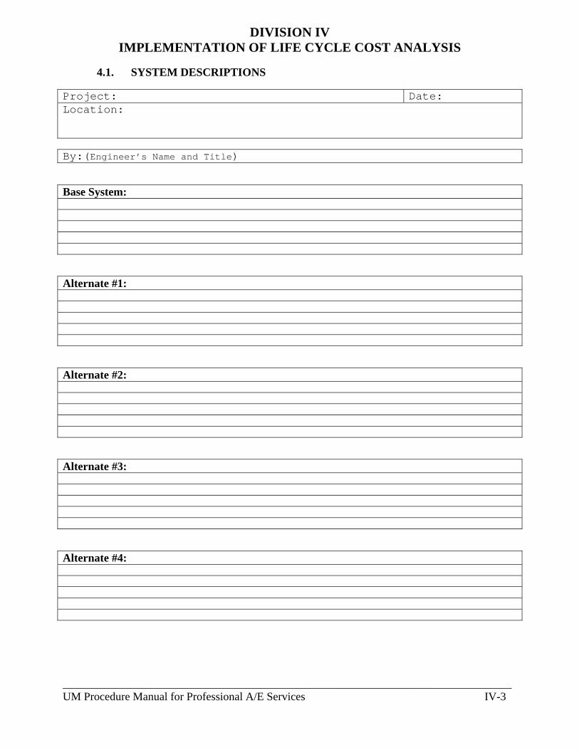
_______________________________________________________________________________ UM Procedure Manual for Professional A/E Services IV-3
DIVISION IV
IMPLEMENTATION OF LIFE CYCLE COST ANALYSIS
4.1. SYSTEM DESCRIPTIONS Project: Date: Location:
By:(Engineer’s Name and Title)
Base System:
Alternate #1:
Alternate #2:
Alternate #3:
Alternate #4:

_______________________________________________________________________________ UM Procedure Manual for Professional A/E Services IV-4
DIVISION IV
IMPLEMENTATION OF LIFE CYCLE COST ANALYSIS
4.2. UTILITY COST DATA ENERGY TYPE COST ESCALATION RATE
Electric Energy Charge
$ Per KWH (Winter) $ Per KWH (Summer)
Electric Demand Charge
$ Per KWH (Winter) $ Per KWH (Summer)
Steam Energy Charge
$ Per MLB (Winter) $ Per MLB (Summer)
Steam Demand Charge
$ Per MLB (Winter) $ Per MLB (Summer)
Gas
$ Per MCF or Therm
Fuel Oil
$ Per Gallon
Others
$ Per Unit
Electric Energy Charge
Utility Summer Rate Months: (from) (to) Utility Winter Rate Months: (from) (to) LCCA Term (Typically 30 Years): Discount Rate:
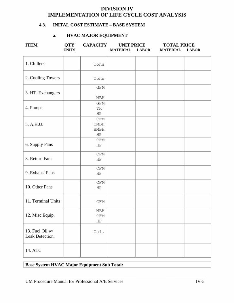
_______________________________________________________________________________ UM Procedure Manual for Professional A/E Services IV-5
DIVISION IV IMPLEMENTATION OF LIFE CYCLE COST ANALYSIS
4.3. INITAL COST ESTIMATE – BASE SYSTEM
a. HVAC MAJOR EQUIPMENT
ITEM QTY CAPACITY UNIT PRICE TOTAL PRICE UNITS MATERIAL LABOR MATERIAL LABOR 1. Chillers
Tons
2. Cooling Towers
Tons
3. HT. Exchangers
GPM MBH
4. Pumps
GPM TH HP
5. A.H.U.
CFM CMBH HMBH HP
6. Supply Fans
CFM HP
8. Return Fans
CFM HP
9. Exhaust Fans
CFM HP
10. Other Fans
CFM HP
11. Terminal Units
CFM
12. Misc Equip.
MBH CFM HP
13. Fuel Oil w/ Leak Detection.
Gal.
14. ATC
Base System HVAC Major Equipment Sub Total:

_______________________________________________________________________________ UM Procedure Manual for Professional A/E Services IV-6
DIVISION IV IMPLEMENTATION OF LIFE CYCLE COST ANALYSIS
b. HVAC MATERIAL
ITEM QTY UNITS UNIT PRICE TOTAL PRICE OF MEASURE MATERIAL LABOR MATERIAL LABOR 1. Supply / Return Ductwork, complete including diffusers, grilles, dampers, insulation etc
2. General Exhaust Ductwork, complete including diffusers, grilles, dampers, insulation etc
3. Special Exhaust Systems
4. Heating Piping (HS, HR)
FEET
5. Chilled Piping (CHS, CHR)
FEET
6. Condenser Water Piping (CWS, CWR)
FEET
8. Steam Piping (MP, LP)
FEET
9. Steam Condensate Piping (MP, LP)
FEET

_______________________________________________________________________________ UM Procedure Manual for Professional A/E Services IV-7
DIVISION IV IMPLEMENTATION OF LIFE CYCLE COST ANALYSIS
b. HVAC MATERIAL (Continued)
ITEM QTY UNITS UNIT PRICE TOTAL PRICE OF MEASURE MATERIAL LABOR MATERIAL LABOR 10. Natural Gas Piping (Non - Lab)
FEET
11. Pipe Insulation
Base System HVAC Material Sub Total:
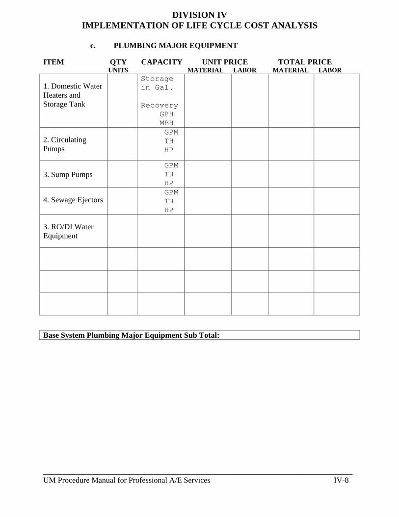
_______________________________________________________________________________ UM Procedure Manual for Professional A/E Services IV-8
DIVISION IV IMPLEMENTATION OF LIFE CYCLE COST ANALYSIS
c. PLUMBING MAJOR EQUIPMENT
ITEM QTY CAPACITY UNIT PRICE TOTAL PRICE UNITS MATERIAL LABOR MATERIAL LABOR 1. Domestic Water Heaters and Storage Tank
Storage in Gal. Recovery GPH MBH
2. Circulating Pumps
GPM TH HP
3. Sump Pumps
GPM TH HP
4. Sewage Ejectors
GPM TH HP
3. RO/DI Water Equipment
Base System Plumbing Major Equipment Sub Total:

_______________________________________________________________________________ UM Procedure Manual for Professional A/E Services IV-9
DIVISION IV IMPLEMENTATION OF LIFE CYCLE COST ANALYSIS
d. PLUMBING MATERIAL
ITEM QTY UNITS UNIT PRICE TOTAL PRICE OF MEASURE MATERIAL LABOR MATERIAL LABOR
1. Domestic Water Piping with Insulation (CW, HW, HWR)
FEET
2. Sanitary & Vent (Non – Lab Above Grade)
3. Sanitary & Vent (Lab – Acid Waste Above Grade)
4. Storm Water (Above Grade)
5. Lab Support Piping – Air, Vac, Natural Gas
6. RO / DI Piping System
7. Sprinkler System, Complete
Base System Plumbing Material Sub Total:
Base System Mechanical Installation Initial Cost Total:

_______________________________________________________________________________ UM Procedure Manual for Professional A/E Services IV-10
DIVISION IV IMPLEMENTATION OF LIFE CYCLE COST ANALYSIS
4.4. INITAL COST ESTIMATE – ALTERNATE SYSTEM #
a. HVAC MAJOR EQUIPMENT
ITEM QTY CAPACITY UNIT PRICE TOTAL PRICE UNITS MATERIAL LABOR MATERIAL LABOR 1. Chillers
Tons
2. Cooling Towers
Tons
3. HT. Exchangers
GPM MBH
4. Pumps
GPM TH HP
5. A.H.U.
CFM CMBH HMBH HP
6. Supply Fans
CFM HP
8. Return Fans
CFM HP
9. Exhaust Fans
CFM HP
10. Other Fans
CFM HP
11. Terminal Units
CFM
12. Misc Equip.
MBH CFM HP
13. Fuel Oil w/ Leak Detection.
Gal.
14. ATC
Alternate System HVAC Major Equipment Sub Total:
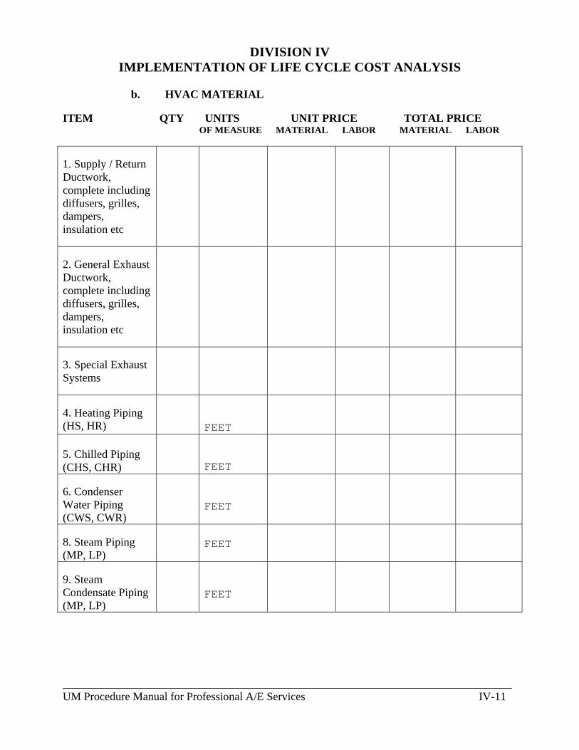
_______________________________________________________________________________ UM Procedure Manual for Professional A/E Services IV-11
DIVISION IV IMPLEMENTATION OF LIFE CYCLE COST ANALYSIS
b. HVAC MATERIAL
ITEM QTY UNITS UNIT PRICE TOTAL PRICE OF MEASURE MATERIAL LABOR MATERIAL LABOR 1. Supply / Return Ductwork, complete including diffusers, grilles, dampers, insulation etc
2. General Exhaust Ductwork, complete including diffusers, grilles, dampers, insulation etc
3. Special Exhaust Systems
4. Heating Piping (HS, HR)
FEET
5. Chilled Piping (CHS, CHR)
FEET
6. Condenser Water Piping (CWS, CWR)
FEET
8. Steam Piping (MP, LP)
FEET
9. Steam Condensate Piping (MP, LP)
FEET

_______________________________________________________________________________ UM Procedure Manual for Professional A/E Services IV-12
DIVISION IV IMPLEMENTATION OF LIFE CYCLE COST ANALYSIS
b. HVAC MATERIAL (Continued)
ITEM QTY UNITS UNIT PRICE TOTAL PRICE OF MEASURE MATERIAL LABOR MATERIAL LABOR 10. Natural Gas Piping (Non - Lab)
FEET
11. Pipe Insulation
Alternate System HVAC Material Sub Total:
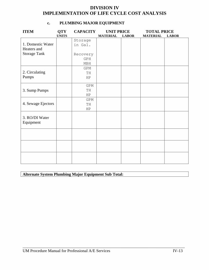
_______________________________________________________________________________ UM Procedure Manual for Professional A/E Services IV-13
DIVISION IV IMPLEMENTATION OF LIFE CYCLE COST ANALYSIS
c. PLUMBING MAJOR EQUIPMENT
ITEM QTY CAPACITY UNIT PRICE TOTAL PRICE UNITS MATERIAL LABOR MATERIAL LABOR 1. Domestic Water Heaters and Storage Tank
Storage in Gal. Recovery GPH MBH
2. Circulating Pumps
GPM TH HP
3. Sump Pumps
GPM TH HP
4. Sewage Ejectors
GPM TH HP
3. RO/DI Water Equipment
Alternate System Plumbing Major Equipment Sub Total:
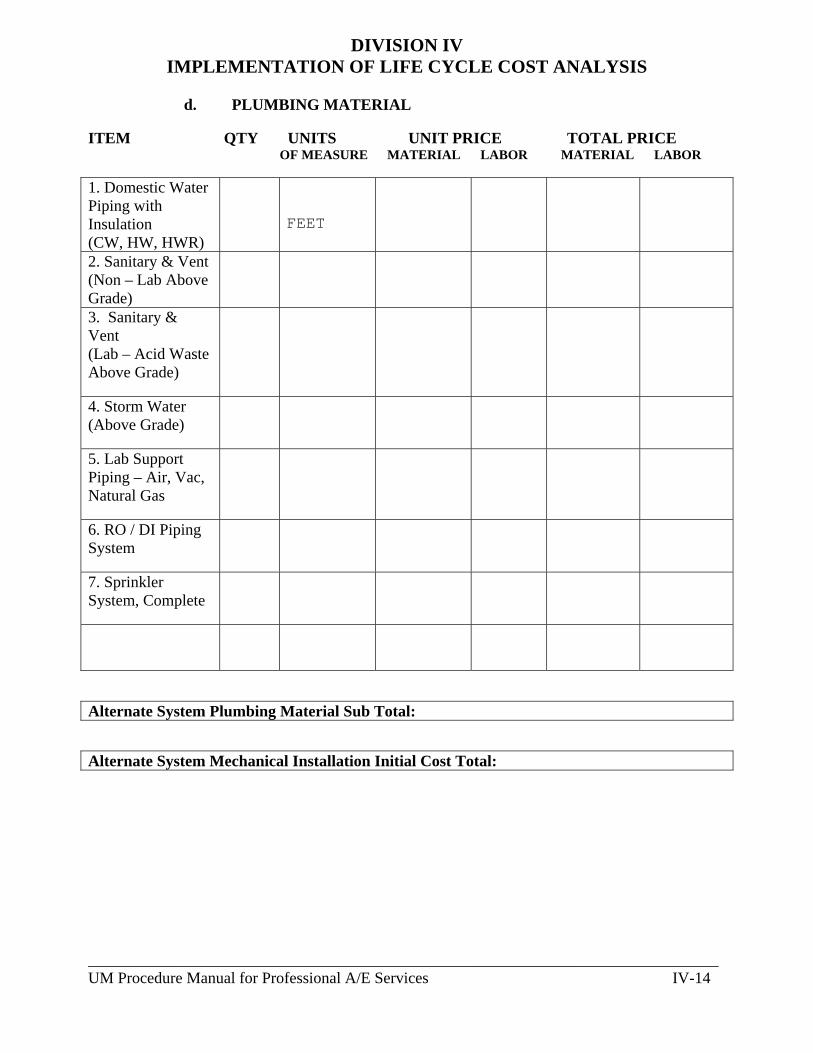
_______________________________________________________________________________ UM Procedure Manual for Professional A/E Services IV-14
DIVISION IV IMPLEMENTATION OF LIFE CYCLE COST ANALYSIS
d. PLUMBING MATERIAL
ITEM QTY UNITS UNIT PRICE TOTAL PRICE OF MEASURE MATERIAL LABOR MATERIAL LABOR
1. Domestic Water Piping with Insulation (CW, HW, HWR)
FEET
2. Sanitary & Vent (Non – Lab Above Grade)
3. Sanitary & Vent (Lab – Acid Waste Above Grade)
4. Storm Water (Above Grade)
5. Lab Support Piping – Air, Vac, Natural Gas
6. RO / DI Piping System
7. Sprinkler System, Complete
Alternate System Plumbing Material Sub Total:
Alternate System Mechanical Installation Initial Cost Total:
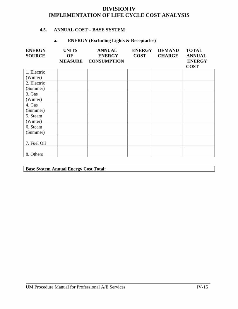
_______________________________________________________________________________ UM Procedure Manual for Professional A/E Services IV-15
DIVISION IV IMPLEMENTATION OF LIFE CYCLE COST ANALYSIS
4.5. ANNUAL COST – BASE SYSTEM
a. ENERGY (Excluding Lights & Receptacles) ENERGY UNITS ANNUAL ENERGY DEMAND TOTAL SOURCE OF ENERGY COST CHARGE ANNUAL MEASURE CONSUMPTION ENERGY
COST 1. Electric (Winter)
2. Electric (Summer)
3. Gas (Winter)
4. Gas (Summer)
5. Steam (Winter)
6. Steam (Summer)
7. Fuel Oil
8. Others
Base System Annual Energy Cost Total:

_______________________________________________________________________________ UM Procedure Manual for Professional A/E Services IV-16
DIVISION IV IMPLEMENTATION OF LIFE CYCLE COST ANALYSIS
b. SERVICE AND MAINTENANCE COST
MAJOR ANNUAL ANNUAL TOTAL SERVICE & EQUIPMENT SERVICE MAINTENANCE MAINTENANCE COST
COST COST 1. Chillers
2. Cooling Towers
3. Heat Exchangers
4. Pumps
5. Air Handling Units
6. Supply Fans
7. Return Fans
8. Exhaust Fans
9. Terminal Units
10. Domestic Water Heaters
11. RO / DI Equipment
12. Exhaust Fans
13. ATC
14. Misc. Equipment
Base System Service and Maintenance Cost Total:

_______________________________________________________________________________ UM Procedure Manual for Professional A/E Services IV-17
DIVISION IV IMPLEMENTATION OF LIFE CYCLE COST ANALYSIS
4.6. SYSTEM REPLACEMENT COST – BASE SYSTEM
PRESENT VALUE OF EQUIPMENT REPLACEMENT COST Major Equipment
Useful Life
Replacement Cost In Current Dollars (RC)
Present Worth Factor (PWF)
Present Value (PV) of Replacement Cost PWF x RC
Base System Present Value of Equipment Replacement Cost Total:

_______________________________________________________________________________ UM Procedure Manual for Professional A/E Services IV-18
DIVISION IV IMPLEMENTATION OF LIFE CYCLE COST ANALYSIS
4.7. ANNUAL COST – ALTERNATE #
a. ENERGY (Excluding Lights & Receptacles) ENERGY UNITS ANNUAL ENERGY DEMAND TOTAL SOURCE OF ENERGY COST CHARGE ANNUAL MEASURE CONSUMPTION ENERGY
COST 1. Electric (Winter)
2. Electric (Summer)
3. Gas (Winter)
4. Gas (Summer)
5. Steam (Winter)
6. Steam (Summer)
7. Fuel Oil
8. Others
Alternate System Annual Energy Cost Total:
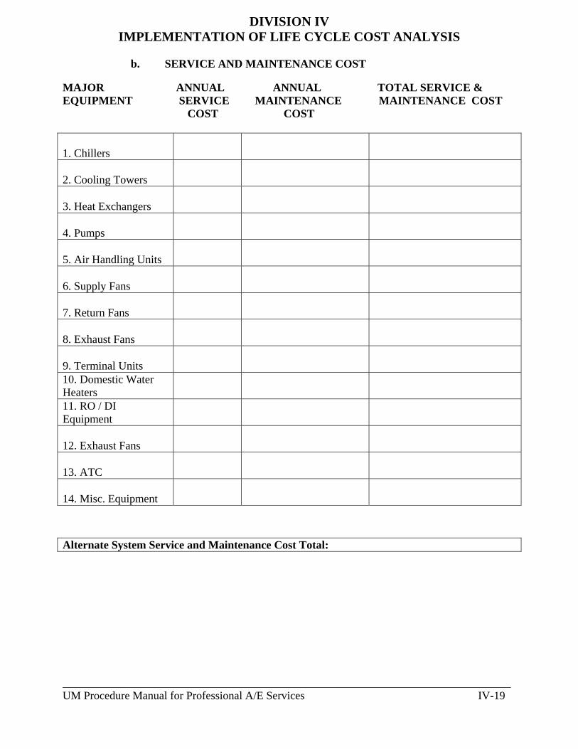
_______________________________________________________________________________ UM Procedure Manual for Professional A/E Services IV-19
DIVISION IV IMPLEMENTATION OF LIFE CYCLE COST ANALYSIS
b. SERVICE AND MAINTENANCE COST
MAJOR ANNUAL ANNUAL TOTAL SERVICE & EQUIPMENT SERVICE MAINTENANCE MAINTENANCE COST
COST COST 1. Chillers
2. Cooling Towers
3. Heat Exchangers
4. Pumps
5. Air Handling Units
6. Supply Fans
7. Return Fans
8. Exhaust Fans
9. Terminal Units
10. Domestic Water Heaters
11. RO / DI Equipment
12. Exhaust Fans
13. ATC
14. Misc. Equipment
Alternate System Service and Maintenance Cost Total:
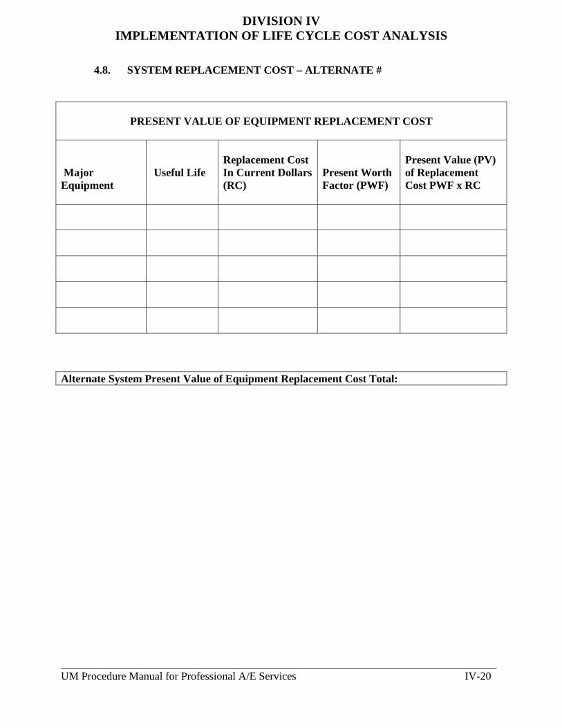
_______________________________________________________________________________ UM Procedure Manual for Professional A/E Services IV-20
DIVISION IV IMPLEMENTATION OF LIFE CYCLE COST ANALYSIS
4.8. SYSTEM REPLACEMENT COST – ALTERNATE #
PRESENT VALUE OF EQUIPMENT REPLACEMENT COST Major Equipment
Useful Life
Replacement Cost In Current Dollars (RC)
Present Worth Factor (PWF)
Present Value (PV) of Replacement Cost PWF x RC
Alternate System Present Value of Equipment Replacement Cost Total:

_______________________________________________________________________________ UM Procedure Manual for Professional A/E Services IV-21
DIVISION IV IMPLEMENTATION OF LIFE CYCLE COST ANALYSIS
4.9. SUMMARY - LCCA PROJECT: DATE: COSTS BASE SYSTEM ALTERNATIVE ALTERNATIVE
#1 #2 1. Mechanical Installation Initial Cost Total
2. Incremental Cost For Architectural Components (+ / - over base system)
N / A
3. Incremental Cost For Structural Components (+ / - over base system)
N / A
4. Incremental Cost For Electrical Components (+ / - over base system)
N / A
Total Initial Cost
Annual Energy Cost
Annual Service Cost
Annual Routine Maintenance Cost
Total Annual Cost
Present Value (PV) of Total Annual Cost (Total Annual Cost x PW Factor)
Present Value of Equipment Replacement Cost
Total Life Cycle Cost (Total Initial Cost + PV of Total Annual Cost + PV of Equipment Replacement Cost)

_______________________________________________________________________________ UM Procedure Manual for Professional A/E Services IV-22
DIVISION IV IMPLEMENTATION OF LIFE CYCLE COST ANALYSIS
4.9. SUMMARY - LCCA (Continued)
PROJECT: DATE: COSTS BASE SYSTEM ALTERNATIVE ALTERNATIVE
#3 #4 1. Mechanical Installation Initial Cost Total
2. Incremental Cost For Architectural Components (+ / - over base system)
N / A
3. Incremental Cost For Structural Components (+ / - over base system)
N / A
4. Incremental Cost For Electrical Components (+ / - over base system)
N / A
Total Initial Cost
Annual Energy Cost
Annual Service Cost
Annual Routine Maintenance Cost
Total Annual Cost
Present Value (PV) of Total Annual Cost (Total Annual Cost x PW Factor)
Present Value of Equipment Replacement Cost
Total Life Cycle Cost (Total Initial Cost + PV of Total Annual Cost + PV of Equipment Replacement Cost)
Recommended System:

DIVISION V
ATTACHMENTS

________________________________________________________________________ UM Procedure Manual for Professional A/E Services V-1
_____________________________________________________________________
DIVISION V ATTACHMENTS
________________________________________________________________________ Latest Update 8-14-14, See underlined text 1. GENERAL REQUIREMENTS:
1.1. A/E Requirements: When required by the University the Architect/Engineer (A/E) assigned by contract to a given project shall utilize the attachments as identified in previous Divisions.
2. ATTACHMENTS:
2.1. Forms: The following forms are modeled after the attachments in the DGS Procedure Manual, July, 2003 Edition.
a. Summary – Areas, Volume & Efficiency Form
b. Tabulation of Gross Area Form
c. Summary – Net Assignable Areas Form
d. University Standard Request For Change Order Proposal Form
e. Engineer’s and Developer’s Certification Form
f. Building Code Study Data Forms
g. Project Description Forms
h. Directions for Completing the Project Description Forms
i. See pages V-3 through V-18 for the samples of the forms.
2.2. University Standard Cover Sheets and Drawing List: a. Cover Sheet - Bound Documents: The University Standard Cover
Sheet shall be used on all projects for all bound specifications, reports, studies etc. prepared by the A/E and submitted to UM.
b. Cover Sheet - Drawings: The University Standard Cover Sheet
shall be used on all projects for all bound drawing sets prepared by the A/E and submitted to UM.

________________________________________________________________________ UM Procedure Manual for Professional A/E Services V-2
c. Standard Drawing List: The University Standard Drawing List
shall be used on all projects for all bound drawing sets prepared by the A/E and submitted to UM.
d. See pages V-19 through V-28 for a sample of the cover sheet for
bound documents and the drawing list.
2.3. Availability: The forms, cover sheets and drawing list are available electronically on the UM Web Site.

________________________________________________________________________ UM Procedure Manual for Professional A/E Services V-3
SUMMARY - AREAS, VOLUME & EFFICIENCY PROJECT: ______________________________ UNIVERSITY PROJECT NO: ________________ FACILITY: _____________________________ DATE: ______________________ ARCHITECT/ENGINEER: ________________________________________________________
ITEM
AREA SQ. FT.
PROGRAM SD DD 50% 95% 100%
GROSS AREA (Notes 1 & 2)
NET ASSIGNABLE AREA (Notes 1 & 2) (Sh. 3 to incl.)
GROSS FACTOR (Note 1)
EFFICIENCY FACTOR (Note 3) % EFFICIENCY (Note 4)
SUBMISSION DATE (Note 5)
NOTES: 1. Gross Areas, Net Assignable Areas and Volumes shall be calculated in strict accordance with the University Procedure Manual. 2. Attach additional sheets as follows: Sheet 2 - Tabulation of Gross Areas; Sheet 3 and subsequent sheets - Tabulation of Net Assignable Areas (Room by Room). 3. To obtain Efficiency Factor: Divide Gross Area by Net Assignable Area (e.g. 49,209 SF
Gross Area divided by 33,705 SF Net Assignable Area = 1.46). 4. To obtain % Efficiency: Divide Net Assignable Area by Gross Area and multiply by 100
(e.g. 33,705 SF Net Assignable Area divided by 49,209 SF Gross Area multiplied by 100 = 68.5% Efficiency)
5. Submit in triplicate to the University Project Manager with each phase submission of the
review documents. Figures shall be shown for all previous phases as well as the current phase submitted.
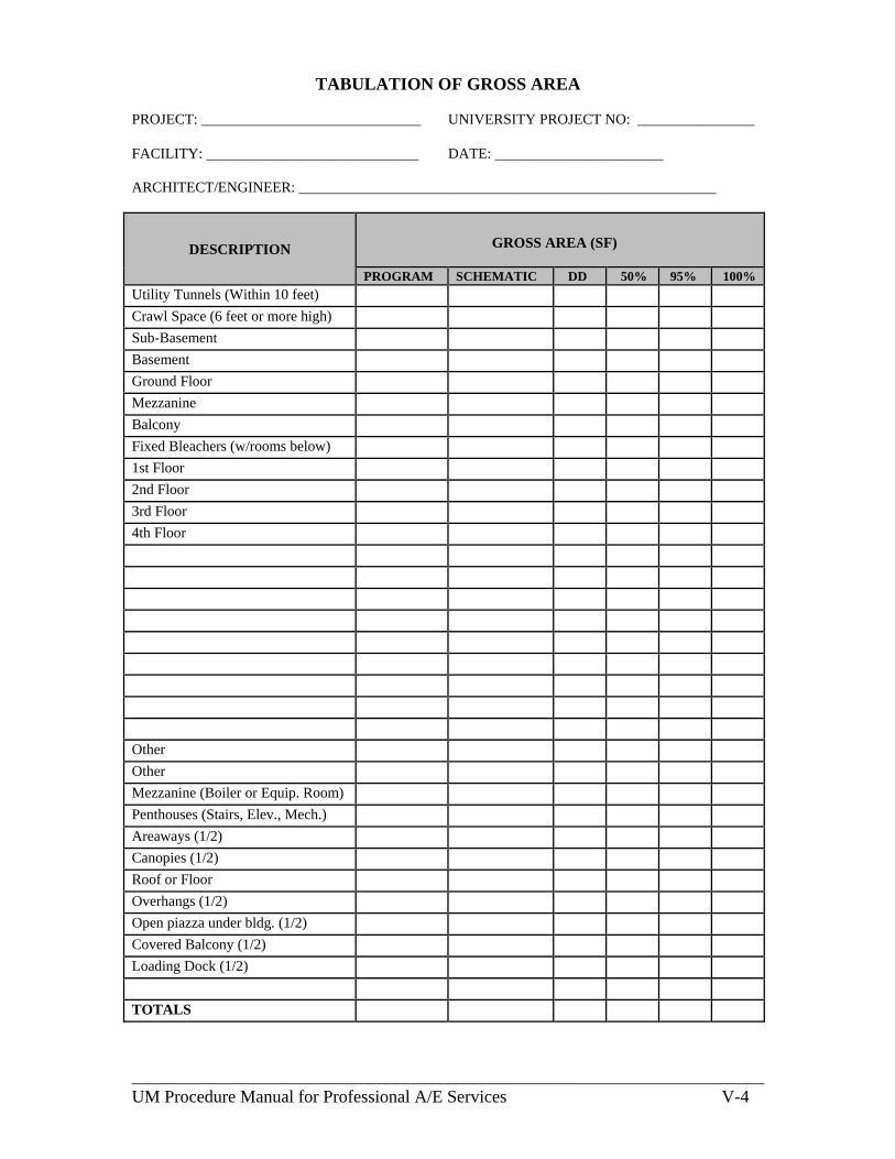
________________________________________________________________________ UM Procedure Manual for Professional A/E Services V-4
TABULATION OF GROSS AREA PROJECT: ______________________________ UNIVERSITY PROJECT NO: ________________ FACILITY: _____________________________ DATE: _______________________ ARCHITECT/ENGINEER: _________________________________________________________
DESCRIPTION
GROSS AREA (SF)
PROGRAM SCHEMATIC DD 50% 95% 100%
Utility Tunnels (Within 10 feet) Crawl Space (6 feet or more high) Sub-Basement Basement Ground Floor Mezzanine Balcony Fixed Bleachers (w/rooms below) 1st Floor 2nd Floor 3rd Floor 4th Floor Other Other Mezzanine (Boiler or Equip. Room) Penthouses (Stairs, Elev., Mech.) Areaways (1/2) Canopies (1/2) Roof or Floor Overhangs (1/2) Open piazza under bldg. (1/2) Covered Balcony (1/2) Loading Dock (1/2) TOTALS

________________________________________________________________________ UM Procedure Manual for Professional A/E Services V-5
TABULATION OF NET ASSIGNABLE AREAS PROJECT: ______________________________ PROJECT NO: ________________ FACILITY: _____________________________ DATE: _______________________ ARCHITECT/ENGINEER: _________________________________________________________
Room No. DESCRIPTION NET ASSIGNABLE AREAS (SF)
PROGRAM SD DD 50% 95% 100%
Total (This Sheet) GRAND TOTAL (Sheet 3 to )

________________________________________________________________________ UM Procedure Manual for Professional A/E Services V-6
RCOP
UM STANDARD PROJECT REQUEST FOR CHANGE ORDER PROPOSAL FORM _______________________________________________________________________ REQUEST FOR CHANGE ORDER PROPOSAL RCO #: PROJECT TITLE: UMB PROJECT #: PREPARED BY: DATE PREPARED: REVIEWED FOR UM BY: DATE REVIEWED:
PLEASE SUBMIT AN ITEMIZED CHANGE ORDER PROPOSAL INDICATING ANY CHANGES TO THE CONTRACT AMOUNT AND/OR CONTRACT SCHEDULE AS A RESULT OF THE IMPLEMENTATION OF THE PROPOSED CHANGES TO THE CONTRACT DOCUMENTS AS DESCRIBED HEREIN. THIS IS NOT A CONTRACT CHANGE ORDER, CONTRACT AMENDMENT, OR DIRECTION TO PROCEED WITH WORK DESCRIBED HEREIN. UM Project Manager: Date: PROPOSED CHANGES TO THE CONTRACT DOCUMENTS: Provide all labor, materials, equipment, and services necessary to accomplish the following revisions and changes to the contract documents. Include all changes in the record set of Record Documents. The modifications to the contract documents as a result of this Request For Change Order Proposal include the following:
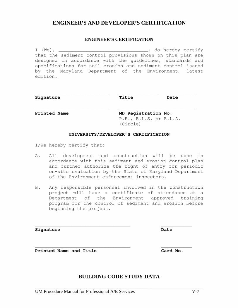
________________________________________________________________________ UM Procedure Manual for Professional A/E Services V-7
ENGINEER’S AND DEVELOPER’S CERTIFICATION
ENGINEER’S CERTIFICATION I (We), ________________________________, do hereby certify that the sediment control provisions shown on this plan are designed in accordance with the guidelines, standards and specifications for soil erosion and sediment control issued by the Maryland Department of the Environment, latest edition. __________________________ ______________ __________ Signature Title Date __________________________ ___________________________ Printed Name MD Registration No.
P.E., R.L.S. or R.L.A. (Circle)
UNIVERSITY/DEVELOPER’S CERTIFICATION
I/We hereby certify that: A. All development and construction will be done in
accordance with this sediment and erosion control plan and further authorize the right of entry for periodic on-site evaluation by the State of Maryland Department of the Environment enforcement inspectors.
B. Any responsible personnel involved in the construction
project will have a certificate of attendance at a Department of the Environment approved training program for the control of sediment and erosion before beginning the project.
__________________________________ ___________ Signature Date __________________________________ ___________ Printed Name and Title Card No.
BUILDING CODE STUDY DATA

________________________________________________________________________ UM Procedure Manual for Professional A/E Services V-8
DESIGN PHASE: __ SD __ DD __ CD DATE: ____________ 1) PROJECT: ___________________ PROJECT NO. _________________
FACILITY: ________________________________________________________ ________________________________________________________
2) APPLICABLE CODES: A) Building Code: IBC – 2006 B) Fire Code: NFPA – 2006 C) International Mechanical Code: IMC – 2006 D) National Standard Plumbing Code: NSPC – 2003 E) National Electric Code: NEC – 2005 F) ASHRAE: Latest G) Elevator and Escalator Safety Code: ASME A17.1.2000 (with
addenda)
3) BUILDING USE, CONSTRUCTION CLASSIFICATIONS AND HEIGHT
IBC NFPA Use Group (Section 302) _________________: ________ ________ Special Use and Occupancy__ ___ (Chapter 4): ________ ________ Incidental Use Areas _______ _ (Table 508.2): ________ ________ Proposed Type of Construction __ (Table 503): ________ ________ Building Height Allowance _____ (Table 503): ________ ________ Additional Credit for Fully Sprinklered Building _________________ (Section 504.2): ________ ________ Actual Building Height __________________: ________ ________ Number of Stories ____________ (Table 503): ________ ________
4) BUILDING AREAS:
BUILDING ACTUAL CROSS AREAS: First Floor : __________________ Second Floor : __________________ Third Floor : __________________ Mechanical Penthouse: __________________ Total (GSF) : __________________
MAXIMUM ALLOWABLE AREAS:
Per IBC Table 503: ______ + Automatic Sprinkler System Increase – 504.2______
5) OCCUPANCY LOADS:
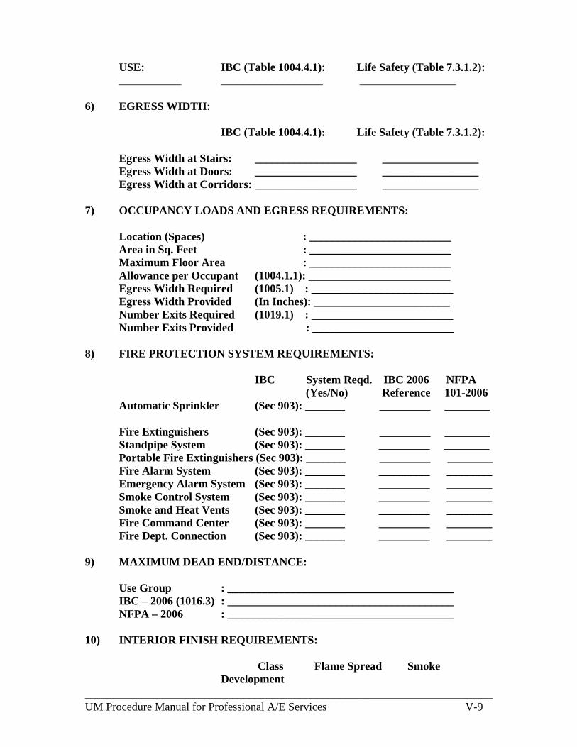
________________________________________________________________________ UM Procedure Manual for Professional A/E Services V-9
USE: IBC (Table 1004.4.1): Life Safety (Table 7.3.1.2): ___________ __________________ _________________
6) EGRESS WIDTH:
IBC (Table 1004.4.1): Life Safety (Table 7.3.1.2): Egress Width at Stairs: __________________ _________________ Egress Width at Doors: __________________ _________________
Egress Width at Corridors: __________________ _________________ 7) OCCUPANCY LOADS AND EGRESS REQUIREMENTS:
Location (Spaces) : _________________________ Area in Sq. Feet : _________________________ Maximum Floor Area : _________________________ Allowance per Occupant (1004.1.1): _________________________ Egress Width Required (1005.1) : _________________________ Egress Width Provided (In Inches): ________________________ Number Exits Required (1019.1) : _________________________ Number Exits Provided : _________________________
8) FIRE PROTECTION SYSTEM REQUIREMENTS:
IBC System Reqd. IBC 2006 NFPA (Yes/No) Reference 101-2006 Automatic Sprinkler (Sec 903): _______ _________ ________ Fire Extinguishers (Sec 903): _______ _________ ________ Standpipe System (Sec 903): _______ _________ ________ Portable Fire Extinguishers (Sec 903): _______ _________ ________ Fire Alarm System (Sec 903): _______ _________ ________ Emergency Alarm System (Sec 903): _______ _________ ________ Smoke Control System (Sec 903): _______ _________ ________ Smoke and Heat Vents (Sec 903): _______ _________ ________ Fire Command Center (Sec 903): _______ _________ ________ Fire Dept. Connection (Sec 903): _______ _________ ________
9) MAXIMUM DEAD END/DISTANCE:
Use Group : ________________________________________ IBC – 2006 (1016.3) : ________________________________________ NFPA – 2006 : ________________________________________
10) INTERIOR FINISH REQUIREMENTS:
Class Flame Spread Smoke
Development

________________________________________________________________________ UM Procedure Manual for Professional A/E Services V-10
IBC – 2006 (Table – 803.5): _______ _____________ _______________ NFPA – 2006 (Chapter 10): _______ _____________ _______________
11) MAXIMUM TRAVEL DISTANCE TO EXIT:
Actual: Show on Life Safety Plan
IBC 2006 (Table – 1015.1) NFPA - 2006 Allowable: ______________________ ___________ 12) MAXIMUM CORRIDOR WIDTH REQUIREMENTS:
Location Width IBC Reference (1017.2) NFPA-Reference _______ _____ ___________________ ______________ 13) PANIC HARDWARE:
Location Required IBC Reference (1008.1.9) NFPA-Reference _______ ________ ___________________ ______________ 14) STAIR DATA: (Section 1009)
Stair Width : _______________________________ Capacity : _______________________________ Rated Enclosure: _______________________________
15) BUILDING FIRE RATINGS:
IBC – 2006 NFPA - 2006 (601-602) (Chapter 8)
STRUCTURAL FRAME : _________ __________ Including Columns, Girders, Trusses EXTERIOR BEARING WALL : _________ __________ EXTERIOR NON-BEARING WALL : _________ __________ INTERIOR BEARING WALL : _________ __________ FLOOR CONSTRUCTION : _________ __________ Including Support Beams and Joist

________________________________________________________________________ UM Procedure Manual for Professional A/E Services V-11
ROOF CONSTRUCTION : _________ __________ Including Support Beams and Joist : _________ FIRE WALLS – USE GROUP : _________ __________ Protective Opening Rating (Section 705 & 715) VERTICAL EXIT ENCLOSURE : _________ __________ Protective Opening Rating (Section 704.4)
SHAFTS AND ELEVATOR HOIST WAYS: _________ __________ Protective Opening Rating (Section 707.4)
EXIT ACCESS CORRIDORS : _________ __________ Protective Opening Rating (Section 1017.1)
SMOKE BARRIER : _________ __________ Protective Opening Rating (Section 709)
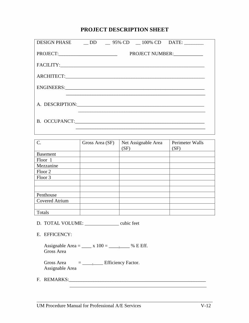
________________________________________________________________________ UM Procedure Manual for Professional A/E Services V-12
PROJECT DESCRIPTION SHEET
DESIGN PHASE __ DD __ 95% CD __ 100% CD DATE: ________ PROJECT:________________________ PROJECT NUMBER:____________ FACILITY:___________________________________________________________ ARCHITECT:_________________________________________________________ ENGINEERS:_________________________________________________________ _________________________________________________________ A. DESCRIPTION:____________________________________________________
____________________________________________________
B. OCCUPANCT:_____________________________________________________ _____________________________________________________
C. Gross Area (SF) Net Assignable Area
(SF) Perimeter Walls (SF)
Basement Floor 1 Mezzanine Floor 2 Floor 3 Penthouse Covered Atrium Totals D. TOTAL VOLUME: ______________ cubic feet E. EFFICENCY:
Assignable Area = ____ x 100 = ____.____ % E Eff. Gross Area Gross Area = ____.____ Efficiency Factor. Assignable Area
F. REMARKS:________________________________________________________
________________________________________________________
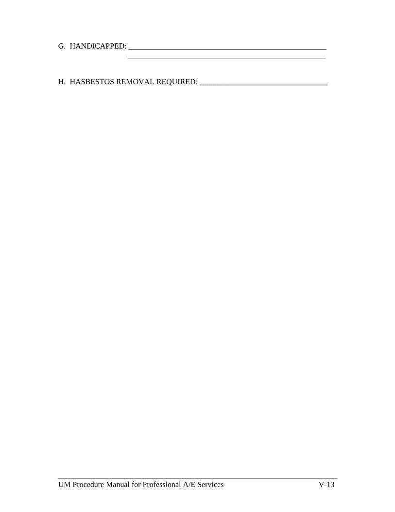
________________________________________________________________________ UM Procedure Manual for Professional A/E Services V-13
G. HANDICAPPED: ___________________________________________________
___________________________________________________ H. HASBESTOS REMOVAL REQUIRED: _________________________________
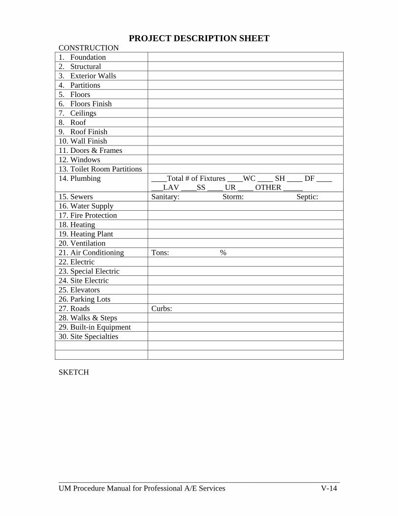
________________________________________________________________________ UM Procedure Manual for Professional A/E Services V-14
PROJECT DESCRIPTION SHEET CONSTRUCTION 1. Foundation 2. Structural 3. Exterior Walls 4. Partitions 5. Floors 6. Floors Finish 7. Ceilings 8. Roof 9. Roof Finish 10. Wall Finish 11. Doors & Frames 12. Windows 13. Toilet Room Partitions 14. Plumbing ____Total # of Fixtures ____WC ____ SH ____ DF ____
___LAV ____SS ____ UR ____ OTHER _____ 15. Sewers Sanitary: Storm: Septic: 16. Water Supply 17. Fire Protection 18. Heating 19. Heating Plant 20. Ventilation 21. Air Conditioning Tons: % 22. Electric 23. Special Electric 24. Site Electric 25. Elevators 26. Parking Lots 27. Roads Curbs: 28. Walks & Steps 29. Built-in Equipment 30. Site Specialties SKETCH

________________________________________________________________________ UM Procedure Manual for Professional A/E Services V-15
DIRECTIONS FOR COMPLETING PROJECT DESCRIPTION SHEET The project Architect/Engineer shall complete a separate Project Description Sheet (Attachment #6) for each building of a project and submit the original with 2 copies to the Department of General Services:
(1) to accompany the design development plans, (2) to accompany the final plans (prior to bid, after all revisions.) And (3) at such other times as requested.
Keep description brief, use abbreviations. GENERAL A. Give brief description of structure. When project has more than one building,
give building title here.
B. State occupancy: Garage or Parking . . . . . . . . . . . . . . . . . . . . . . . . . . . . . . . . . . number of vehicles; Nursing Home, Dormitory or Hospital . . . . . . . number of student or patient beds; Auditorium or Gym . . . . . . . . . . . . . . . . . . . . . . . . . . . . . . . . . . . . number of seats; Housing . . . . . . . . . . . . . . . . . . . . . . . . . . . . . . . . . . . . . . . . number of rental units; Library . . . . . . . . . . . . . . .number of volumes, number of carrels, number of seats,
(including carrels); Dining Hall . . . . . . . . . . . . . . . . . . . . . serving capacity per hour, number of seats; Kitchen . . . . . . . . . . . . . . . . . . . . . . . . . . . . . . . . . . . . . . . . . . . . . . . meal capacity; University Academic Buildings . . . . . . . . . . . . . . . number students each building,
number of classrooms, number of faculty offices; Public Schools . . . . . . . . . . . . . . . . . number of pupils, number of faculty offices,
number of classrooms; Office of Administration Building . . . . . . . . . . . . . . . . . .number of personnel; etc; Court Houses . . . . . . . . . . . . . . . . . . . . . . number of courtrooms, number of seats;
C. Give gross area in square feet, assignable area in square feet and length of perimeter walls in linear feet for each floor or level. Gross and Assignable Areas shall be figured on the basis of Assignable Area and Supporting (unassignable) Areas as defined in appendix D of this manual.
D. State gross volume of structure in cubic feet. Use height from underside of lowest floor construction system to average top of finished roof surface for each portion of areas above. For slabs on grade, use height from bottom of gravel.
E. Figure efficiency both ways as indicated: as a percent and as a factor (e.g. 60% and 1.67).
F. For additional information or continuation of other items.
G. State whether facilities for the handicapped are included.

________________________________________________________________________ UM Procedure Manual for Professional A/E Services V-16
H. State whether asbestos abatement is required.
I. Draw a one-line plan view to a small scale; give basic dimensions and indicate
number of stories of each portion of facility.
CONSTRUCTION 1. State types - spread footings, caissons, piles (timber, pipe, h, precast concrete,
cast-in place, pressure injected, etc.), grade beams, etc. If footings are on engineered fill, so state.
2. State types - structural steel, reinforced concrete, precast units, wall bearing or
structural frame, timber, post-tensioned, etc. 3. State type and materials - curtain or bearing, solid or cavity, brick, brick and
block, precast, metal, wood frame, with or without insulation, etc.
4. State type and materials - fixed or movable, bearing or non-bearing, brick, block, tile, metal, precast, gypsum, metal or wood stud and sheet-and-rock, concrete, etc.
5. State type and materials - precast or poured-in-place concrete, steel deck or form with concrete fill, steel or wood joist, flat slab, etc.
6. State finish materials - resilient flooring, concrete, carpeting, terrazzo, etc. (State total square yard area of carpeting and terrazzo). (Do not include toilet rooms in this item.)
7. State finish materials. (Do not include toilet rooms in this item.)
8. State construction - flat or pitched, wood, concrete or steel framing, metal deck, concrete slab, precast, gypsum plank, etc.
9. State materials - built-up, slate, asphalt shingles, galvanized, copper, etc.
10. State finish materials - paint, epoxy coatings, ceramic tile, glazed block,
wainscots, plaster, etc. (Do not include toilet rooms in this item.)
11. State type and material - hollow metal or wood, solid core wood, glass aluminum and glass, overhead, roll-up, revolving, etc. (Include type of frames - hollow metal, steel, wood, etc.)
12. State type and material - fixed double hung, projected, casement, sliding, awning,
pivoted, window wall, aluminum, wood, steel, stainless steel, bronze, etc.
13. State types and materials of construction and finishes for floor, walls, ceiling, including wainscots, type of toilet partitions, etc.

________________________________________________________________________ UM Procedure Manual for Professional A/E Services V-17
14. State number of each type plumbing fixture; give total number. Add types not listed in places provided. Give size and type of domestic water heater. Use the following abbreviations: WC - toilet SS - service sink Lav - lavatory UK - unit kitchen U - urinal LS - Lab sink SH - shower head KS - kitchen sink SC - shower compartment PS - pot sink BT - bathtub DS - dish sink LT - laundry tub FD - food waste disposal SB - special bath BP - bed pan sterilizer HB - hose bibb DF - drinking fountain WH - water heater WTC - water cooler
15. State type of material, size and length (over 10 feet from building) for each type and size of sewer. State the type and capacity (gallons) of septic system.
16. State type of materials, size and length (over 10 feet from building) of water lines.
If from wells, state number and capacity. Include hot and cold water lines from a central facility.
17. State types and locations - sprinklers, standpipes, smoke or heat detectors, fire alarm system, extinguishers, hydrants, Fire Department connections, etc.
18. State types of systems including types of temperature control systems.
19. State whether plant is individual (state fuel) or central. State size and length (over 10 feet from building) of each outside line (steam, hot water, cold water, etc.) from a central plant.
20. Brief description. State cubic feet per minute quantities of total outside air and total exhaust air.
21. State types of systems, air conditioning tonnage, percentage of building that is air conditioned.
22. State service, distribution and utilization voltages, phase, amperage, overhead or underground service (give length over 10 feet from building), wiring method of building such as type, concealed or exposed, etc.
23. State electrical specialties such as audio-visual, stage lighting, lightning
protection, intrusion protection, communication systems, emergency systems (e.g. battery units or generator), time system, power for computers, etc.
24. State items of site electric, such as exterior lighting, sub-station, etc.
25. State type and number of elevators, dumbwaiters, moving stairs, etc.
26. State type of construction, area in square yards and number of vehicles.

________________________________________________________________________ UM Procedure Manual for Professional A/E Services V-18
27. State type of construction and area in square yards. Give type of curbs and length in feet.
28. State type of construction and area in square yards.
29. State what built-in-equipment is included in project such as kitchen, snack bar, exhaust hood, special refrigeration, cabinet work, laboratory equipment, library stacks, wardrobes, special exhaust or waste systems, chalk and tack boards, draperies, pedestal floor (give area), etc.

________________________________________________________________________ UM Procedure Manual for Professional A/E Services V-19

________________________________________________________________________ UM Procedure Manual for Professional A/E Services V-20
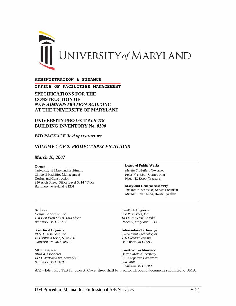
________________________________________________________________________ UM Procedure Manual for Professional A/E Services V-21
ADMINISTRATION & FINANCE
OFFICE OF FACILITIES MANAGEMENT
SPECIFICATIONS FOR THE CONSTRUCTION OF NEW ADMINISTRATION BUILDING AT THE UNIVERSITY OF MARYLAND UNIVERSITY PROJECT # 06-418 BUILDING INVENTORY No. 8100 BID PACKAGE 3a-Superstructure VOLUME 1 OF 2: PROJECT SPECFICATIONS March 16, 2007 Owner
Board of Public Works
University of Maryland, Baltimore Office of Facilities Management Design and Construction 220 Arch Street, Office Level 3, 14th Floor Baltimore, Maryland 21201
Martin O’Malley, Governor Peter Franchot, Comptroller Nancy K. Kopp, Treasurer Maryland General Assembly Thomas V. Miller Jr, Senate President Michael Erin Busch, House Speaker
Architect Design Collective, Inc. 100 East Pratt Street, 14th Floor Baltimore, MD 21202 Structural Engineer RESTL Designers, Inc. 13 Firstfield Road, Suite 200 Gaithersburg, MD 208781 MEP Engineer BKM & Associates 1423 Clarkview Rd., Suite 500 Baltimore, MD 21209
Civil/Site Engineer Site Resources, Inc. 14307 Jarrettsville Pike Phoenix, Maryland 21131 Information Technology Convergent Technologies 426 Evesham Avenue Baltimore, MD 21212 Construction Manager Barton Malow Company 971 Corporate Boulevard Suite 400 Linthicum, MD 21090
A/E – Edit Italic Text for project. Cover sheet shall be used for all bound documents submitted to UMB.
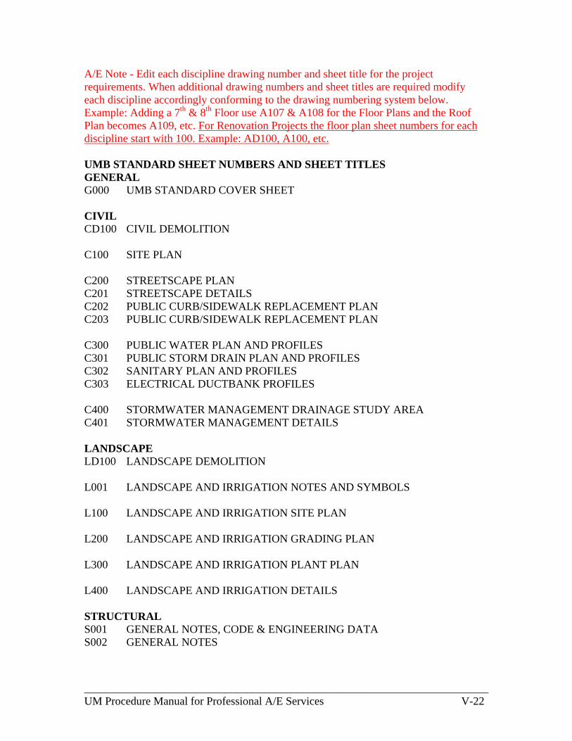
________________________________________________________________________ UM Procedure Manual for Professional A/E Services V-22
A/E Note - Edit each discipline drawing number and sheet title for the project requirements. When additional drawing numbers and sheet titles are required modify each discipline accordingly conforming to the drawing numbering system below. Example: Adding a 7th & 8th Floor use A107 & A108 for the Floor Plans and the Roof Plan becomes A109, etc. For Renovation Projects the floor plan sheet numbers for each discipline start with 100. Example: AD100, A100, etc. UMB STANDARD SHEET NUMBERS AND SHEET TITLES GENERAL G000 UMB STANDARD COVER SHEET
CIVIL CD100 CIVIL DEMOLITION C100 SITE PLAN C200 STREETSCAPE PLAN C201 STREETSCAPE DETAILS C202 PUBLIC CURB/SIDEWALK REPLACEMENT PLAN C203 PUBLIC CURB/SIDEWALK REPLACEMENT PLAN C300 PUBLIC WATER PLAN AND PROFILES C301 PUBLIC STORM DRAIN PLAN AND PROFILES C302 SANITARY PLAN AND PROFILES C303 ELECTRICAL DUCTBANK PROFILES C400 STORMWATER MANAGEMENT DRAINAGE STUDY AREA C401 STORMWATER MANAGEMENT DETAILS LANDSCAPE LD100 LANDSCAPE DEMOLITION L001 LANDSCAPE AND IRRIGATION NOTES AND SYMBOLS L100 LANDSCAPE AND IRRIGATION SITE PLAN L200 LANDSCAPE AND IRRIGATION GRADING PLAN L300 LANDSCAPE AND IRRIGATION PLANT PLAN L400 LANDSCAPE AND IRRIGATION DETAILS
STRUCTURAL S001 GENERAL NOTES, CODE & ENGINEERING DATA S002 GENERAL NOTES

________________________________________________________________________ UM Procedure Manual for Professional A/E Services V-23
SD100 BASEMENT FLOOR DEMOLITION PLAN SD101 FIRST FLOOR DEMOLITION PLAN SD102 SECOND FLOOR DEMOLITION PLAN SD103 THIRD FLOOR DEMOLITION PLAN SD104 FOURTH FLOOR DEMOLITION PLAN SD105 FIFTH FLOOR DEMOLITION PLAN SD106 SIXTH FLOOR DEMOLITION PLAN SD107 ROOF DEMOLITION PLAN S100 FOUNDATION AND BASEMENT FLOOR FRAMING PLAN S101 FIRST FLOOR FRAMING PLAN S102 SECOND FLOOR FRAMING PLAN S103 THIRD FLOOR FRAMING PLAN S104 FOURTH FLOOR FRAMING PLAN S105 FIFTH FLOOR AND LOW ROOF FRAMING PLAN S106 SIXTH FLOOR FRAMING PLAN S107 ROOF AND MACHINE ROOM FRAMING PLAN S108 ROOF FRAMING PLAN S200 FOUNDATION WALL ELEVATIONS AND SECTIONS S300 TYPICAL DETAILS S301 TYPICAL DETAILS S302 TYPICAL DETAILS S400 SECTIONS AND DETAILS S401 SECTIONS AND DETAILS S402 SECTIONS AND DETAILS S403 SECTIONS AND DETAILS S500 COLUMN SCHEDULE ARCHITECTURAL A001 GENERAL NOTES SYMBOLS AND ABBREVIATIONS A002 CODE ANALYSIS, FEDERAL ACCESSIBILITY STANDARDS, AND
BUILDING CONSTRUCTION STANDARDS A003 LIFE SAFETY BASEMENT AND FIRST FLOOR PLANS A004 LIFE SAFETY SECOND AND THIRD FLOOR PLANS A005 LIFE SAFETY FOURTH AND FIFTH FLOOR PLANS A006 LIFE SAFETY SIXTH FLOOR AND ROOF PLANS AD100 BASEMENT FLOOR DEMOLITION PLAN AD101 FIRST FLOOR DEMOLITION PLAN AD102 SECOND FLOOR DEMOLITION PLAN AD103 THIRD FLOOR DEMOLITION PLAN AD104 FOURTH FLOOR DEMOLITION PLAN

________________________________________________________________________ UM Procedure Manual for Professional A/E Services V-24
AD105 FIFTH FLOOR DEMOLITION PLAN AD106 SIXTH FLOOR DEMOLITION PLAN AD107 ROOF DEMOLITION PLAN A100 BASEMENT FLOOR PLAN A101 FIRST FLOOR PLAN A102 SECOND FLOOR PLAN A103 THIRD FLOOR PLAN A104 FOURTH FLOOR PLAN A105 FIFTH FLOOR PLAN A106 SIXTH FLOOR PLAN A107 PENTHOUSE FLOOR PLAN A108 ROOF PLAN A120 BASEMENT FLOOR REFLECTED CEILING PLAN A121 FIRST FLOOR REFLECTED CEILING PLAN A122 SECOND FLOOR REFLECTED CEILING PLAN A123 THIRD FLOOR REFLECTED CEILING PLAN A124 FOURTH FLOOR REFLECTED CEILING PLAN A125 FIFTH FLOOR REFLECTED CEILING PLAN A126 SIXTH FLOOR REFLECTED CEILING PLANS A127 PENTHOUSE REFLECTIVE CEILING PLAN A130 BASEMENT FLOOR FINISH PLAN AND KEY PLAN A131 FIRST FLOOR FINISH PLAN AND KEY PLAN A132 SECOND FLOOR FINISH PLAN AND KEY PLAN A133 THIRD FLOOR FINISH PLAN AND KEY PLAN A134 FOURTH FLOOR FINISH PLAN AND KEY PLAN A135 FIFTH FLOOR FINISH PLAN AND KEY PLAN A140 BASEMENT FLOOR SIGNAGE PLAN A141 FIRST FLOOR SIGNAGE PLAN A142 SECOND FLOOR SIGNAGE PLAN A143 THIRD FLOOR SIGNAGE PLAN A144 FOURTH FLOOR SIGNAGE PLAN A145 FIFTH FLOOR SIGNAGE PLAN A146 SIXTH FLOOR AND ROOF SIGNAGE PLANS A200 EXTERIOR ELEVATIONS A201 ELEVATIONS A202 ELEVATIONS A210 EXTERIOR ENLARGED ELEVATIONS A211 EXTERIOR ENLARGED ELEVATIONS A220 INTERIOR ELEVATIONS
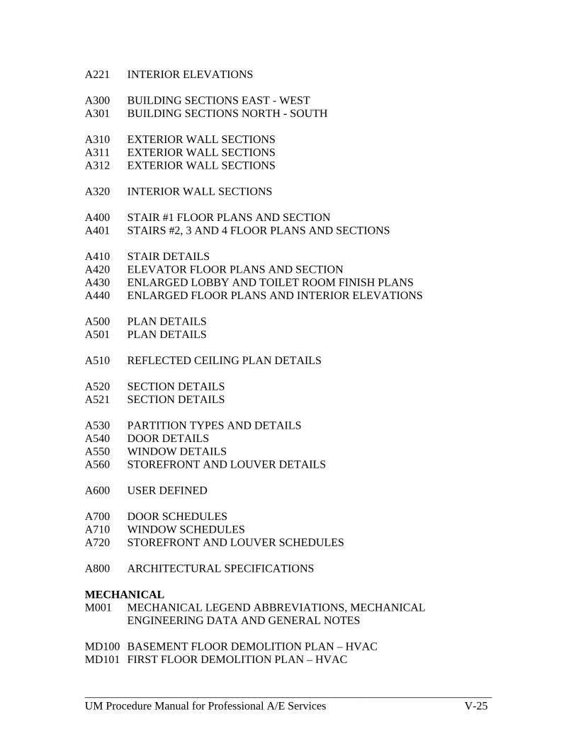
________________________________________________________________________ UM Procedure Manual for Professional A/E Services V-25
A221 INTERIOR ELEVATIONS A300 BUILDING SECTIONS EAST - WEST A301 BUILDING SECTIONS NORTH - SOUTH A310 EXTERIOR WALL SECTIONS A311 EXTERIOR WALL SECTIONS A312 EXTERIOR WALL SECTIONS A320 INTERIOR WALL SECTIONS A400 STAIR #1 FLOOR PLANS AND SECTION A401 STAIRS #2, 3 AND 4 FLOOR PLANS AND SECTIONS A410 STAIR DETAILS A420 ELEVATOR FLOOR PLANS AND SECTION A430 ENLARGED LOBBY AND TOILET ROOM FINISH PLANS A440 ENLARGED FLOOR PLANS AND INTERIOR ELEVATIONS A500 PLAN DETAILS A501 PLAN DETAILS A510 REFLECTED CEILING PLAN DETAILS A520 SECTION DETAILS A521 SECTION DETAILS A530 PARTITION TYPES AND DETAILS A540 DOOR DETAILS A550 WINDOW DETAILS A560 STOREFRONT AND LOUVER DETAILS A600 USER DEFINED A700 DOOR SCHEDULES A710 WINDOW SCHEDULES A720 STOREFRONT AND LOUVER SCHEDULES A800 ARCHITECTURAL SPECIFICATIONS MECHANICAL M001 MECHANICAL LEGEND ABBREVIATIONS, MECHANICAL
ENGINEERING DATA AND GENERAL NOTES MD100 BASEMENT FLOOR DEMOLITION PLAN – HVAC MD101 FIRST FLOOR DEMOLITION PLAN – HVAC
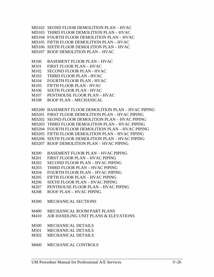
________________________________________________________________________ UM Procedure Manual for Professional A/E Services V-26
MD102 SEOND FLOOR DEMOLITION PLAN – HVAC MD103 THIRD FLOOR DEMOLITION PLAN – HVAC MD104 FOURTH FLOOR DEMOLITION PLAN – HVAC MD105 FIFTH FLOOR DEMOLITION PLAN – HVAC MD106 SIXTH FLOOR DEMOLITION PLAN – HVAC MD107 ROOF DEMOLITION PLAN – HVAC M100 BASEMENT FLOOR PLAN – HVAC M101 FIRST FLOOR PLAN – HVAC M102 SECOND FLOOR PLAN - HVAC M103 THIRD FLOOR PLAN - HVAC M104 FOURTH FLOOR PLAN - HVAC M105 FIFTH FLOOR PLAN - HVAC M106 SIXTH FLOOR PLAN - HVAC M107 PENTHOUSE FLOOR PLAN – HVAC M108 ROOF PLAN – MECHANICAL MD200 BASEMENT FLOOR DEMOLITION PLAN – HVAC PIPING MD201 FIRST FLOOR DEMOLITION PLAN – HVAC PIPING MD202 SEOND FLOOR DEMOLITION PLAN – HVAC PIPING MD203 THIRD FLOOR DEMOLITION PLAN – HVAC PIPING MD204 FOURTH FLOOR DEMOLITION PLAN – HVAC PIPING MD205 FIFTH FLOOR DEMOLITION PLAN – HVAC PIPING MD206 SIXTH FLOOR DEMOLITION PLAN – HVAC PIPING MD207 ROOF DEMOLITION PLAN – HVAC PIPING M200 BASEMENT FLOOR PLAN – HVAC PIPING M201 FIRST FLOOR PLAN – HVAC PIPING M202 SECOND FLOOR PLAN – HVAC PIPING M203 THIRD FLOOR PLAN – HVAC PIPING M204 FOURTH FLOOR PLAN – HVAC PIPING M205 FIFTH FLOOR PLAN – HVAC PIPING M206 SIXTH FLOOR PLAN – HVAC PIPING M207 PENTHOUSE FLOOR PLAN – HVAC PIPING M208 ROOF PLAN – HVAC PIPING M300 MECHANICAL SECTIONS M400 MECHANICAL ROOM PART PLANS M410 AIR HANDLING UNIT PLANS & ELEVATIONS M500 MECHANICAL DETAILS M501 MECHANICAL DETAILS M502 MECHANICAL DETAILS M600 MECHANICAL CONTROLS

________________________________________________________________________ UM Procedure Manual for Professional A/E Services V-27
M610 COOLING SYSTEM SCHEMATIC DIAGRAM M620 HEATING SYSTEM SCHEMATIC DIAGRAM M630 ENERGY RECOVERY SCHEMATIC DIAGRAM M640 AIR DISTRIBUTION SCHEMATIC DIAGRAM M700 MECHANICAL SCHEDULES M701 MECHANICAL SCHEDULES M702 MECHANICAL SCHEDULES M703 MECHANICAL SCHEDULES M800 MECHANICAL SPECIFICATIONS PLUMBING P001 PLUMBING LEGEND & GENERAL NOTES PD100 BASEMENT FLOOR DEMOLITION PLAN – PLUMBING PD101 FIRST FLOOR DEMOLITION PLAN – PLUMBING PD102 SEOND FLOOR DEMOLITION PLAN – PLUMBING PD103 THIRD FLOOR DEMOLITION PLAN – PLUMBING PD104 FOURTH FLOOR DEMOLITION PLAN – PLUMBING PD105 FIFTH FLOOR DEMOLITION PLAN – PLUMBING PD106 SIXTH FLOOR DEMOLITION PLAN – PLUMBING PD107 ROOF DEMOLITION PLAN – PLUMBING P100 BASEMENT FLOOR PLAN – PLUMBING P101 FIRST FLOOR PLAN – PLUMBING P102 SECOND FLOOR PLAN - PLUMBING P103 THIRD FLOOR PLAN - PLUMBING P104 FOURTH FLOOR PLAN - PLUMBING P105 FIFTH FLOOR PLAN - PLUMBING P106 SIXTH FLOOR PLAN – PLUMBING P107 PENTHOUSE FLOOR PLAN – PLUMBING P108 ROOF PLAN – PLUMBING P400 PART PLANS – PLUMBING P500 PLUMBING DETAILS P600 DOMESTIC WATER RISER DIAGRAMS P610 SANITARY RISER DIAGRAMS P620 STORM WATER RISER DIAGRAM P630 LABORATORY COMPRESSER AIR AND VACUUM SYSTEM
DIAGRAMS P640 RO / DI WATER SYSTEM DIAGRAMS P700 PLUMBING SCHEDULES

________________________________________________________________________ UM Procedure Manual for Professional A/E Services V-28
FIRE PROTECTION FP001 FIRE PROTECTION LEGEND, GENERAL NOTES FPD100 BASEMENT FLOOR DEMOLITION PLAN – SPRINKLER FPD101 FIRST FLOOR DEMOLITION PLAN – SPRINKLER FPD102 SEOND FLOOR DEMOLITION PLAN – SPRINKLER FPD103 THIRD FLOOR DEMOLITION PLAN – SPRINKLER FPD104 FOURTH FLOOR DEMOLITION PLAN – SPRINKLER FPD105 FIFTH FLOOR DEMOLITION PLAN – SPRINKLER FPD106 SIXTH FLOOR DEMOLITION PLAN – SPRINKLER FPD107 ROOF DEMOLITION PLAN – SPRINKLER FP100 BASEMENT FLOOR PLAN – SPRINKLER FP101 FIRST FLOOR PLAN – SPRINKLER FP102 SECOND FLOOR PLAN - SPRINKLER FP103 THIRD FLOOR PLAN - SPRINKLER FP104 FOURTH FLOOR PLAN - SPRINKLER FP105 FIFTH FLOOR PLAN - SPRINKLER FP106 SIXTH FLOOR PLAN – SPRINKLER FP107 PENTHOUSE FLOOR PLAN – SPRINKLER FP108 ROOF PLAN – SPRINKLER FP400 PART PLAN – SPRINKLER FP500 SPRINKLER DETAILS FP600 FIRE PROTECTION RISER DIAGRAM ELECTRICAL E001 LEGEND, ABBREVIATIONS & ELECTRICAL ENGINEERING DATA ED100 BASEMENT FLOOR DEMOLITION PLAN – POWER ED101 FIRST FLOOR DEMOLITION PLAN – POWER ED102 SEOND FLOOR DEMOLITION PLAN – POWER ED103 THIRD FLOOR DEMOLITION PLAN – POWER ED104 FOURTH FLOOR DEMOLITION PLAN – POWER ED105 FIFTH FLOOR DEMOLITION PLAN – POWER ED106 SIXTH FLOOR DEMOLITION PLAN – POWER ED107 ROOF DEMOLITION PLAN – POWER E100 BASEMENT FLOOR PLAN – POWER E101 FIRST FLOOR PLAN – POWER E102 SECOND FLOOR PLAN – POWER E103 THIRD FLOOR PLAN – POWER E104 FOURTH FLOOR PLAN – POWER E105 FIFTH FLOOR PLAN – POWER

________________________________________________________________________ UM Procedure Manual for Professional A/E Services V-29
E106 SIXTH FLOOR PLAN – POWER E107 PENTHOUSE FLOOR PLAN – POWER E108 ROOF PLAN – POWER ED200 BASEMENT FLOOR DEMOLITION PLAN – LIGHTING ED101 FIRST FLOOR DEMOLITION PLAN – LIGHTING ED202 SEOND FLOOR DEMOLITION PLAN – LIGHTING ED203 THIRD FLOOR DEMOLITION PLAN – LIGHTING ED204 FOURTH FLOOR DEMOLITION PLAN – LIGHTING ED205 FIFTH FLOOR DEMOLITION PLAN – LIGHTING ED206 SIXTH FLOOR DEMOLITION PLAN – LIGHTING ED207 ROOF DEMOLITION PLAN – LIGHTING E200 BASEMENT FLOOR PLAN – LIGHTING E201 FIRST FLOOR PLAN – LIGHTING E202 SECOND FLOOR PLAN – LIGHTING E203 THIRD FLOOR PLAN – LIGHTING E204 FOURTH FLOOR PLAN – LIGHTING E205 FIFTH FLOOR PLAN – LIGHTING E206 SIXTH FLOOR PLAN – LIGHTING E207 PENTHOUSE FLOOR PLAN – LIGHTING E208 ROOF PLAN – LIGHTING E600 ONE-LINE RISER DIAGRAM E601 FIRE ALARM RISER DIAGRAM E602 FIRE ALARM GRAPHIC ANNUNCIATOR E700 ELECTRICAL PANEL SCHEDULE E710 LIGHTING SCHEDULE E800 ELECTRICAL SPECIFICATIONS AUDIO VISUAL AND TELECOMMUNICATIONS TA001 AUDIO VISUAL AND TELECOMMUNICATIONS TITLE SHEET TA101 TELECOMMUNICATIONS SYSTEM OSP TA102 TELECOMMUNICATIONS RISER DETAILS TA103 TELECOMMUNICATIONS DETAILS TA104 TELECOMMUNICATIONS RACK ELEVATIONS TA105 TELECOMMUNICATIONS RACK ELEVATIONS TA200 AUDIO VISUAL AND TELECOMMUNICATIONS BASEMENT FLOOR
PLAN TA201 AUDIO VISUAL AND TELECOMMUNICATIONS FIRST FLOOR PLAN TA202 AUDIO VISUAL AND TELECOMMUNICATIONS SECOND FLOOR PLAN TA203 AUDIO VISUAL AND TELECOMMUNICATIONS THIRD FLOOR PLAN TA204 AUDIO VISUAL AND TELECOMMUNICATIONS FOURTH FLOOR PLAN

________________________________________________________________________ UM Procedure Manual for Professional A/E Services V-30
TA205 AUDIO VISUAL AND TELECOMMUNICATIONS FIFTH FLOOR PLAN TA206 AUDIO VISUAL AND TELECOMMUNICATIONS SIXTH FLOOR PLAN SECURITY TY001 SYMBOLS, LEGENDS & ABBREVIATIONS – SECURITY TY100 BASEMENT FLOOR PLAN - SECURITY TY101 FIRST FLOOR PLAN – SECURITY TY103 THIRD FLOOR PLAN – SECURITY TY105 FIFTH FLOOR PLAN – SECURITY TY107 ROOF PLAN – SECURITY TY500 DETAILS, DOORS AND RACK ELEVATION TY501 DETAILS – CCTV CAMERAS TY600 RISERS – SECURITY TY601 RISERS – SECURITY DOOR DEVICES TY602 RISERS – SECURITY SYSTEM
End of Division V