proceedings template - word · web viewincorporating rbac into the jxta p2p infrastructure amit...
TRANSCRIPT
Incorporating RBAC into the JXTA P2P Infrastructure
Amit Mathur
Computer Science Department
San Jose State University
San Jose, CA 95192
408-924-1000
Table of Contents1. Abstract........................................................................................................................................... 12. Introduction..................................................................................................................................... 2
2.1 RBAC Overview...................................................................................................................... 22.2 P2P Overview.......................................................................................................................... 4
3. JXTA Overview............................................................................................................................... 63.1 Peers........................................................................................................................................ 83.2 Peer Groups............................................................................................................................. 93.3 Network Transport (Endpoints, Peer Pipes and Messages).......................................................93.4 Services................................................................................................................................. 103.5 Advertisements...................................................................................................................... 103.6 Communication challenges in a P2P setup.............................................................................103.7 Protocols................................................................................................................................ 12
3.7.1 Peer Discovery Protocol................................................................................................. 123.7.2 Rendevous Protocol (RVP)............................................................................................153.7.3 Peer Information Protocol (PIP).....................................................................................193.7.4 Pipe Binding Protocol.................................................................................................... 23
4. Example P2P Application.............................................................................................................. 265. Implementation of RBAC into JXTA............................................................................................. 28
5.1 Authentication vs. Authorization............................................................................................ 285.2 RBAC Resource..................................................................................................................... 28
6. Application Design........................................................................................................................ 296.1 Technology decisions............................................................................................................. 29
The choice of XML :.............................................................................................................................. 296.2 JXTA Sockets........................................................................................................................ 316.3 Application Overview............................................................................................................ 316.4 Detailed Design...................................................................................................................... 326.5 XML Engine.......................................................................................................................... 33
Defining Roles :..................................................................................................................................... 33Define mapping between a Peer and a Role :........................................................................................36
6.6 RBAC engine......................................................................................................................... 366.7 Execution Engine................................................................................................................... 386.8 Class Diagram........................................................................................................................ 416.9 Sequence diagrams................................................................................................................. 42
6.9.1 Local peer execution...................................................................................................... 426.9.2 Remote Execution: Client Sequence...............................................................................43
i
6.9.3 Remote Execution: Server Sequence.............................................................................436.9.4 RBAC security policy enforcement................................................................................45
6.10 Tests and Results.................................................................................................................... 467. Conclusion..................................................................................................................................... 488. Future Work.................................................................................................................................. 489. References..................................................................................................................................... 50
ii
1. Abstract
Role Based Access Control (RBAC) is a technique that allows users access to resources based on their
competencies and responsibilities within an organization. Typically, RBAC is provided as security
mechanism for a single host at the operating system level. This allows the operating system to ensure
that an authenticated user has access to resources (typically programs and files) based on their role. With
the advent of distributed systems, the need to have the same level of flexibility at the application level
(which spans multiple hosts) is increased.
Due to the inherent security issues of the peer to peer (P2P) distributed architecture based on the
lack of centralized administration, it seems reasonable that an application developer would want to use
RBAC to restrict access to a distributed P2P application in a way that reflects the responsibilities of each
peer. I have developed an RBAC interface for the Juxtapose (JXTA) P2P framework, which is a popular
open P2P technology specification lead by SUN Microsystems. This will allow a JXTA application
developer to focus on the application that they are developing and leave the authorization to this
framework.
Keywords
Peer, P2P, JXTA, RBAC
1

2. Introduction
In this paper, I discuss Role Based Access Control (RBAC) as a flexible authorization mechanism. I
then go on to elaborate on concepts related to Peer to Peer (P2P) networks and SUN Microsystem’s
specification of JXTA which enables P2P computing. Finally, I bring these concepts together and
discuss an approach to incorporate RBAC into JXTA.
I have created a reference implementation of the approach that demonstrates the capabilities of
this model. I have also produced a demonstration application that uses the reference implementation and
illustrates the concepts. I discuss in detail the design of the reference implementation including both
static and dynamic system interactions. I also discuss the test results of the demonstration application
which exercises the reference implementation.
2.1 RBAC Overview
Role Based Access Control (RBAC) is an authorization mechanism that allows flexible administration
while allowing users to have access to the resources that they need. In an RBAC framework, users are
associated with roles, and roles are associated with operations. A key premise behind RBAC is the
concept of least privilege. Users only have the minimum amount of privileges they need to accomplish
their tasks.
An important capability of RBAC is the ability for an administrator to define a role and assign
and remove users to and from that role as necessary. This is important due to the fact that although users
come and go, the roles typically are static. This is in contrast to ‘standard’ UNIX permissions where a
user is directly associated to a resource (file) via owner and group permissions. RBAC also provides for
the concept of role hierarchies so that related roles can be expressed via inheritance relationships [3].
2

Instead of having to define roles one by one, an administrator can describe roles with respect to other
roles.
RBAC also allows for the capability of separation of duties. Separation of duties means that in a
certain scenario, the same person should not be allowed to be a part of multiple roles. For example, in a
transaction that requires a person to initiate a payment and another person to authorize the payment, in
may not be appropriate for the same person to be both roles as it could mean a breach of the security
practices.
RBAC fits well with object oriented techniques as access to a resource equates to access to an
object method. A role then equates to the concept of an interface. An interface is simply a set of
methods that provide some capability. An interface abstracts away the implementation from the object
that is implementing it. Similarly, in a distributed peer to peer environment, the interface may be
implemented by any given peer.
RBAC differs from other access control mechanisms such as Discretionary access control
(DAC). Whereas DAC allows the user to pass on permissions to other users at their discretion, RBAC
does not provide this capability. RBAC is in fact a form of mandatory access control (MAC). It does
not, however, focus on multilevel security requirements which require classifications of data. Instead, it
focuses on operations that that role is capable of performing.
RBAC is relevant in a P2P environment since many of the applications that are being developed
have clearly defined roles. These roles have defined operations that they can perform. In this situation,
the peer takes the place as the user. An example of this would be a buyer/seller application. Peer A
could be the buyer and Peer B could be the seller. In this situation, we would want to ensure that Peer A
only has access to the appropriate methods on Peer B and visa versa.
3
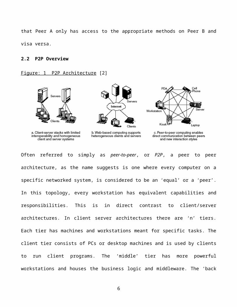
2.2 P2P Overview
Figure: 1 P2P Architecture [2]
Often referred to simply as peer-to-peer, or P2P, a peer to peer architecture, as the name suggests is one
where every computer on a specific networked system, is considered to be an ‘equal’ or a ‘peer’. In this
topology, every workstation has equivalent capabilities and responsibilities. This is in direct contrast to
client/server architectures. In client server architectures there are ‘n’ tiers. Each tier has machines and
workstations meant for specific tasks. The client tier consists of PCs or desktop machines and is used by
clients to run client programs. The ‘middle’ tier has more powerful workstations and houses the
business logic and middleware. The ‘back end’ or the ‘end’ tier also tends to have powerful servers
which house the database and data. In addition, client server architecture has dedicated servers to
manage communication between all the other computers. A Peer-to-peer architecture, however, may be
regarded as an architecture with no ‘tiers’. The distribution of functions is more ad-hoc and is not
architected in tiers. All workstations in a peer to peer architecture are typically equally powerful and
are capable of performing functions of equal caliber. P2P architectures tend to be simpler than client
server networks in the sense a direct communication channel can be established between two parties
without going through a ‘middle man’. However they tend to not perform very well under high loads.
[7] This is because in the P2P architecture there is no concept of a ‘load-balancer’. High performing
4
client-server architectures have load balancers which can determine the load of the different
workstations and distribute the load so no one workstation gets overloaded and its resources over-
utilized. In this manner the operation of the different computers is monitored and managed. In P2P
however due to the lack of a coordinator or controller, this type of control does not exist. [7]
The lack of central administration brings about challenges with regards to how nodes might
publish the resources they have and the services they provide. Traditionally there are three types of P2P
architectures each of which have their mechanism of node discovery [7].
Atomistic P2P (A2P2P): This in many ways may be regarded as the true and traditional ‘P2P’
architecture due to the lack of centralized administration [7]. In this topology every node in truly
independent and manages its resources and connectivity. If a new node would like to join an A2P2P
network, it could either use a broadcast protocol to indicate it’s interest in joining the group and await a
response. Also, it can attempt to connect to a suitable ‘known’ node and from there on listen to the
network and discover the other nodes in the network [7].
User Centric P2P (UCP2P): User Centric P2P adds to A2P2P by providing a ‘bare-bones’
mediating service. Also known as Directory Centric P2P, in this form of P2P, there is a directory of
active nodes. Typically these nodes are identified by means of a unique identification. New nodes may
join an existing UCP2P network by using this directory to establish a connection with an existing node.
The basis for discovery and connection to a specific node is its identity [7].
Data Centric P2P (DCP2P): Data Centric P2P is conceptually similar to UCP2P, except that the
directory maps resources to nodes rather than names to nodes. This is also therefore called Resource
Centric P2P, thus there is knowledge of services and resources that every node in the DCP2P network
provides. Typically these nodes are identified by means of a unique identification. New nodes may join
an existing UCP2P network by using this directory to establish a connection with an existing node. As
5
part of the registration process, clients, need to provide a list of available resources on their node to the
DCP2P server. The basis for discovery and connection to a specific node is the resources it has [7].
The lack of central administration also brings about challenges with regards to who should have
access to what resource. Clearly, each application can develop a mechanism to restrict access to the
resources that it provides, but this approach requires the developer to focus on access control instead of
simply the development task at hand [6].
P2P technology has given rise to powerful and popular applications such as:
- File sharing
- Instant Messaging
- Web based meetings
- Interactive gaming
- Sharing CPU and storage resources
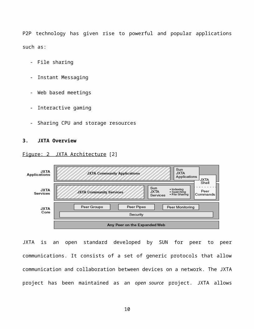
3. JXTA Overview
Figure: 2 JXTA Architecture [2]
JXTA is an open standard developed by SUN for peer to peer communications. It consists of a set of
generic protocols that allow communication and collaboration between devices on a network. The JXTA
6
project has been maintained as an open source project. JXTA allows disparate devices to communicate
and interoperate seamlessly. Portable Digital Assistants (PDAs) may communicate with servers and cell
phones may communicate with PDAs using JXTA. All the participating elements in a JXTA framework
are referred to as ‘peers’. Thus in an environment where a cell phone, server and PDA communicate,
each is considered a peer. In this manner JXTA technology enables the creation of a virtual/logical layer
above the physical layer. In doing so, a P2P architecture is built over the physical layer, taking the
complexity out of the network and physical layer.
Seamless interoperability is a key phenomenon of JXTA. Peers in a JXTA framework can share
resources and collaborate irrespective of their operating systems, their physical location (local, remote,
or behind the firewall or in the DMZ) or the type of device they actually are. Before JXTA, P2P
applications were comprised of chat applications where the two connected devices were ‘compatible’.
However with JXTA, resources can be shared between systems even if the provider of the resource
operates on a platform that is different from the consumer of that resource. This represents true
collaboration and enables efficient resource utilization.
A classic example of the use of JXTA is by the National Association of Realtors. By using
JXTA, various realtor databases can participate in the P2P framework enabling search over varied
databases without importing all the data into a centralized database. In this manner the different
databases are autonomous and owned and managed by individual organizations. However the
information can be far reaching and can server a wide audience as a search can span across multiple
databases.
Based on the fact that JXTA does not have a directory service to find peers, it is an example of
an AP2P or ‘pure’ P2P model. Now that we have described JXTA the need for JXTA, let us take a
7
closer look at basic JXTA terminology: Peers, Peer groups, Network transport, Services and
Advertisements.
3.1 Peers
The fundamental building block of JXTA is a peer. In the traditional P2P domain a peer was defined as
a single application instance running on a single machine. However in the JXTA world a ‘peer’ is much
more than that. It could be a distributed application that resides on multiple machines. On the other
hand, several peer instances might reside on a single physical machine. A peer might also be a hand held
machine such as a PDA that is ‘plugged in’ through it’s cradle. Although a peer is typically a host, it
really is just any “node” capable of speaking the JXTA protocols [1]. There are three types of peers:
Simple Peer: A simple peer typically is a node that exists behind a corporate firewall. It’s
accessibility to the outside world is limited by restrictions imposed by the firewall. They are referred to
as ‘simple’ peers because they have minimal responsibility in that they cannot directly communicate
with other peers and they cannot act as the communication go-between peers.
Rendezvous Peer: As the name suggests a rendezvous peer maybe regarded as a ‘hub’ that peers
query to discover one another. Typically a rendezvous peer resides outside the firewall. Peers query a
rendezvous peer to discover other peers and network location of other peers. The rendezvous peer may
utilize the help of other rendezvous peers to assist in peer discovery. The rendezvous peer may also
cache peer information for use in the future.
Router Peer : A router peer is typically used to route requests between peers. Typically the router
peer exists outside of the firewall in the ‘external’ internet environment. Peers behind corporate
firewalls and NATs route requests back and forth between each other by using a Router peer.
8
3.2 Peer Groups
In the non-JXTA world, the network is divided based on the type of P2P application. Different P2P
applications use different protocols. For example all peers involved in instance messaging would speak
the ICQ protocol and that constitutes one network segment. Peers involved in file sharing speak the
Gnutella protocol which constitutes a different network segment. However in the JXTA world all peers
speak the same protocols, a set of generic, open JXTA protocols. Hence to divide the network a concept
of peer groups is essential. Peer groups are comprised of a set of peers that contribute towards providing
a common service and have a common goal.
For peers to communicate, they must first form a peer group. A peer group is detected via a peer
group advertisement. The join functionality for a peer group is to allow access to anyone, but can be
customized to suit other requirements. The default peer group is called the netPeerGroup. This peer
group acts as a bootstrapping mechanism to allow a peer to access the capabilities of a peer group. The
peer may then join other peer groups as necessary.
3.3 Network Transport (Endpoints, Peer Pipes and Messages)
Network transport is the communication layer that is employed by peers to communicate with each
other. There are three aspects to the Network transport:
Endpoints: This represents the source or destination point of the network that a piece of data gets
transmitted from or transmitted to.
Pipes: The communication mechanism between peers is a peer pipe. A peer pipe is similar to a UNIX
pipe in that is allows unidirectional communication from a peer to another peer. Peers are discovered via
peer advertisements. To communicate using pipes a peer has to first identify a source end point and a
destination end point. A pipe is then bound to these two end points. The pipe is not used for actual data
transmission. It merely represents ‘virtually’ that data is being transmitted between the two bound end
9
points. The end points themselves interface with the network to transmit data. When bound by means of
a pipe the source end point is called the output pipe and the destination end point is called the input
pipe. To send data from one end point to another, data is ‘wrapped’ in a message and pushes it by means
of the output pipe. The peer at the other end then receives the message from the input pipe and extracts
it. Pipes serve as unidirectional communication channels. To implement bi-directional communication,
two pipes are used.
Messages: This refers to the ‘wrapper’ in which data is transmitted using pipes from one end point to
another.
3.4 Services
Services refer to functionality provided by peers. For example, file sharing. There are different types of
services. Peer Services refers to services provided by a single peer to other peers on a network. Peer
Group Sevices refers to services provided by a peer group to its members. If one peer is connected to the
network and provides a service, it is available to all peers in the group. Multiple peers in a peer group
may provide the same service.
3.5 Advertisements
Advertisements are the way by which peers and peer groups make known the services they provide and
services that are available to other peers in a P2P network. In the JXTA world, peers, peer groups,
pipes, end points and services may all be defined using advertisements.
3.6 Communication challenges in a P2P setup
Firewalls and NAT impose challenges on communication between peers. Typically firewalls are used by
corporations to secure their networks. Firewall implementations restrict access to the internal network
by use of Access Control Lists (ACLs), specific IP addresses, specific protocols and specific ports.
10
Typically firewalls allow HTTP for peers inside the network to communicate with the outside. Thus a
peer would have to restrict itself to the use of HTTP. Further if the incoming request does not come in
via the specified port or IP address then the response might get blocked.
NAT implementations on the other hand allow communication back to a machine that originated
a request. Thus there is practically no way for a peer outside of a NAT setup to talk to a peer and the
peer inside the NAT setup would have to first initiate a connection. These limitations are overcome to
some extent by using a proxy or otherwise called a router peer. In a single firewall or NAT traversal,
peer A, a peer behind the firewall sends a message bound for peer B, outside the firewall to a router peer
which is also outside the firewall. Router peer forwards the message to peer B. Peer B then sends a
message back that is bound for peer A to the router peer. Peer A periodically polls the router peer for
messages. The router peer then pushes the response to peer A.
In a double firewall or NAT situation typically the publisher sits inside one firewall and the
subscriber sits inside a different firewall, thus two firewalls have to be traversed. In this situation peer A
behind firewall A sends a message bound for peer B to a router peer that’s in ‘external’ environment.
Peer B which is behind firewall B routinely polls the router peer for messages. The router peer then
pushes the message to peer B.
By using the technique described above, JXTA helps overcome these challenges by specifying a
set of protocols that enable these peers to ‘free’ themselves out of their actually physical location and
communicate freely with one another. As long as the peers speak the JXTA protocols they can publish
their services and resources and consume each others services and resources without having to use
intermediary ‘routing’ peers as described in the above scenario. Let us now take a closer look at the
JXTA protocols.
11
3.7 Protocols
3.7.1 Peer Discovery Protocol
As covered in the ‘Advertisement’ section, advertisements may be regarded as the fundamental unit of
exchange. Having said that, the problem of discovering peers and their resources becomes one of
discovering advertisements corresponding to those resources. The Peer Discovery Protocol defines a
protocol that is used by peers to request advertisements corresponding to resources they are seeking
from other peers and respond to advertisement requests from other peers.
The Peer Discovery Protocol defines two message formats :
1. An advertisement Request Format which is used to discover resources. This format is called the
Discovery Query Message
2. An advertisement Response Format which is used by peers to respond to an advertisement
discovery request. This format is called the Discovery Response Message
These two message formats contain all the information needed for two peers to discover one another.
Let us take a more detailed look at these two message formats.
The Discovery Query Message format :
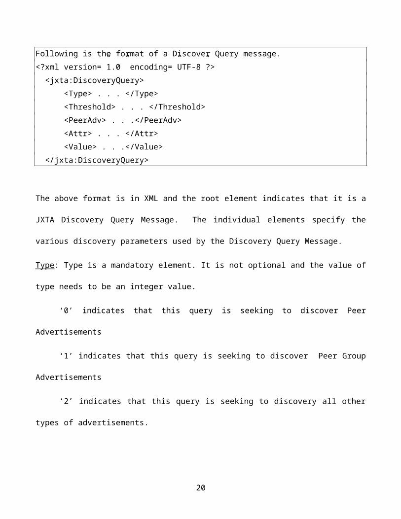
Following is the format of a Discover Query message.<?xml version=”1.0” encoding=”UTF-8”?> <jxta:DiscoveryQuery> <Type> . . . </Type> <Threshold> . . . </Threshold> <PeerAdv> . . .</PeerAdv> <Attr> . . . </Attr> <Value> . . .</Value> </jxta:DiscoveryQuery>
12
The above format is in XML and the root element indicates that it is a JXTA Discovery Query Message.
The individual elements specify the various discovery parameters used by the Discovery Query
Message.
Type: Type is a mandatory element. It is not optional and the value of type needs to be an integer value.
‘0’ indicates that this query is seeking to discover Peer Advertisements
‘1’ indicates that this query is seeking to discover Peer Group Advertisements
‘2’ indicates that this query is seeking to discovery all other types of advertisements.
Threshold: This element is not required. If used it indicates the maximum number of advertisements that
should be sent by a peer that is responding to the discovery query.
PeerAdv: This element is also optional. If specified it indicates contains the Peer Advertisement for the
peer that is requesting the discovery query. In other words it contains the identification of the requesting
peer. This will enable other peers on the network to identify the requesting peer and respond to it with
the results of its query
Attribute and Value: These elements are specified in pairs and are optional as well. They detail the
criteria that an advertisement must meet in order to be sent back as a response to the query. ‘Attr’
specifies the criteria name and ‘Value’ specifies the criteria value.
There are a few exceptions to element values:
1. If Type and Threshold are set to 0, this means that the requesting peer is seeking to discover
maximum Peer Advertisements. As a result all peers that receive the query should respond with their
Peer Advertisement.
13
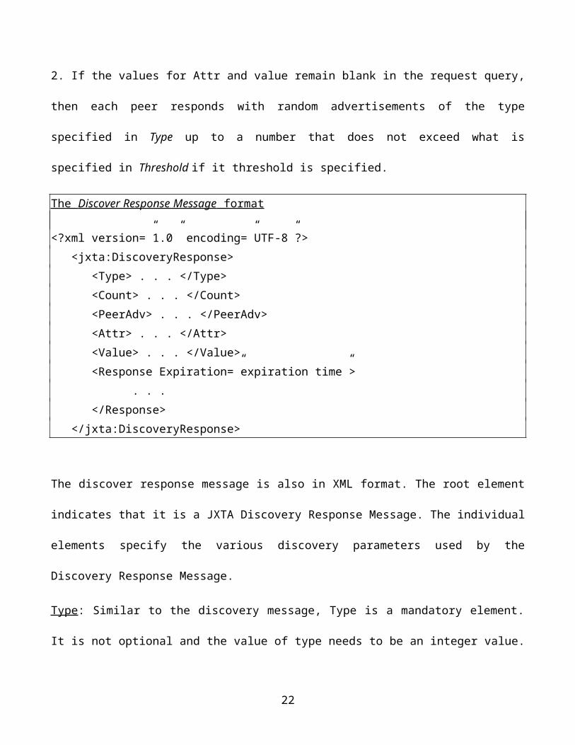
2. If the values for Attr and value remain blank in the request query, then each peer responds with
random advertisements of the type specified in Type up to a number that does not exceed what is
specified in Threshold if it threshold is specified.
The Discover Response Message format
<?xml version=”1.0” encoding=”UTF-8”?> <jxta:DiscoveryResponse> <Type> . . . </Type> <Count> . . . </Count> <PeerAdv> . . . </PeerAdv> <Attr> . . . </Attr> <Value> . . . </Value> <Response Expiration=”expiration time”> . . . </Response> </jxta:DiscoveryResponse>
The discover response message is also in XML format. The root element indicates that it is a JXTA
Discovery Response Message. The individual elements specify the various discovery parameters used
by the Discovery Response Message.
Type: Similar to the discovery message, Type is a mandatory element. It is not optional and the value of
type needs to be an integer value.
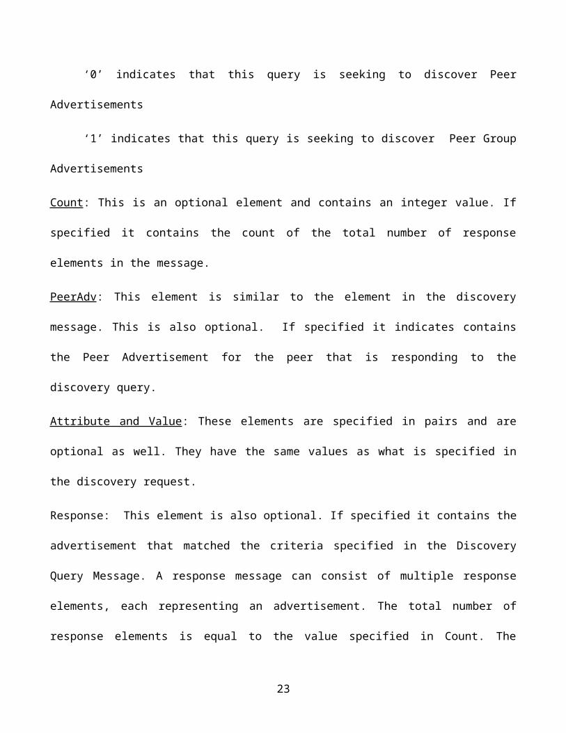
‘0’ indicates that this query is seeking to discover Peer Advertisements
‘1’ indicates that this query is seeking to discover Peer Group Advertisements
Count: This is an optional element and contains an integer value. If specified it contains the count of the
total number of response elements in the message.
14
PeerAdv: This element is similar to the element in the discovery message. This is also optional. If
specified it indicates contains the Peer Advertisement for the peer that is responding to the discovery
query.
Attribute and Value: These elements are specified in pairs and are optional as well. They have the same
values as what is specified in the discovery request.
Response: This element is also optional. If specified it contains the advertisement that matched the
criteria specified in the Discovery Query Message. A response message can consist of multiple response
elements, each representing an advertisement. The total number of response elements is equal to the
value specified in Count. The Expiration attribute in the response element specifies the time for which
the advertisement is authentic and valid.
The Peer Discover Protocol provides a Discovery service which uses the above two message
formats to publish advertisements locally or remotely and retrieve advertisements locally and remotely.
The Java reference implementation provides an interface called the DiscoveryService interface which
aids in the discovery task.
3.7.2 Rendevous Protocol (RVP)
As discussed in the section under ‘Peers’, a rendezvous peer is one which facilitates communication
between two otherwise unreachable peers. Simple peers that reside in a private network connect to a
rendezvous peer by employing the Rendezvous protocol in order to ‘pass on’ messages to other simple
peers that are present in a different private network.
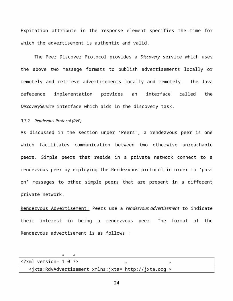
Rendezvous Advertisement: Peers use a rendezvous advertisement to indicate their interest in being a
rendezvous peer. The format of the Rendezvous advertisement is as follows :
15
<?xml version=”1.0”?> <jxta:RdvAdvertisement xmlns:jxta=”http://jxta.org”> <RdvGroupId> . . . </RdvGroupId> <RdvPeerId> . . . </RdvPeerId> <Name> . . . </Name> </jxta:RdvAdvertisement>
As can be seen this message format is in XML.
RdvGroupId: The rendezvous peer provides services to a peer group. This is a mandatory element and
represents the ID of that peer group to which this peer provides rendezvous services.
RdvPeerId: This is again a mandatory element and contains the ID of the peer that provides the
rendezvous services to the above listed peer group.
Name: This element is not mandatory. If specified it represents the name of the rendezvous peer which
may be employed by other peers to find it.
Peers may discover a rendezvous peer by sending out a Discovery Query Message for rendezvous
advertisements.
When using the rendezvous protocol, a peer may not start using the services of the rendezvous peer soon
after discovering one. The peer has to request a lease of the rendezvous peer. This lease may be either
granted or denied by the rendezvous peer. If the lease is granted then there is a time period in which this
lease is valid. Once that time expires, so does the lease and the peer may no longer avail of the
rendezvous peer’s rendezvous services.
Let us look at the lease mechanism is greater detail. There are three types of lease messages,
Lease Request Message, Lease Granted Message and Lease Cancel Message.
16
Lease Request Message : Upon discovering a rendezvous peer that a simple peer would like to use, the
simple peer must send it a request for connection in the form of a lease request message. When sending
this request the simple peer must also send the rendezvous peer it’s own peer advertisement. This is
done by means of a jxta:Connect message element. Following is the XML format of the same,
<jxta:Connect> <jxta:PA xmlns:jxta=”http://jxta.org”> . . . </jxta:PA></jxta:Connect>
The end point service renders this message on a format suitable to be transmitted on the network
transport. Hence this message may get compressed into a binary format, nevertheless above is the
message element specification used by peers.
Lease Granted Message : If the rendezvous peer approves the request for connection from a simple peer,
it generates a lease granted message which contains the ID of the rendezvous peer as well as a time limit
on the granted lease. The lease granted message has the following message elements :
jxta:ConnectedPeer: This element is not optional and contains the rendezvous peer’s peer ID.
jxta:ConnectedLease: This element is mandatory and contains the time for which the lease is valid. This
contains the lease time in miiliseconds as a string. When the lease time limit for a simple peer
connection has lapsed, the rendezvous peer simply eliminates that peer from it’s list of connected peers
jxta:RdvAdvReply: This element is optional and if specified contains the rendezvous peer’s Peer
Advertisement.
17
Lease Cancel Message: If a simple peer would like to discontinue it’s connection with a rendezvous
peer, it issues a lease cancel message. It does so by issuing a disconnect message. The JXTA element is
called,
jxta:Disconnect: This element contains the Peer Advertisement of the peer requesting
removal from a rendezvous peer that it is connected to.
Containing Loop Backs : As can be concurred, if message transmission is not contained, a message
could infinitely be transmitted between a peer and it’s rendezvous peer that are connected in a closed
loop. To avoid this, the RVP allows a message format called Rendezvous Propagate Message. The
XML format for this message is as seen below,
<?xml version=”1.0” encoding=”UTF-8”?> <jxta:RendezVousPropagateMessage> <MessageId> . . . </MessageId> <DestSName> . . . </DestSName> <DestSParam> . . . </DestSParam> <TTL> . . . </TTL> <Path> . . . </Path> </jxta:RendezVousPropagateMessage>
The element of interest here in the TTL element. This is a mandatory element. The TTL or Time To
Live value gets decremented by one anytime the message is exchanged between peers. When the TTL
value reaches 0, the message is discarded by the rendezvous peer eliminating infinite duplicate
propagations of a message.
The Rendezvous Propagate Message specified details about the service to which this message is
being propogated. MessageId as the name suggests contain the ID of the message. The DestSName and
18
DestSParam elements contain the name of the destination services as well as parameters for this
destination service. All of these three elements are mandatory as well.
The Rendezvous Service : The Rendezvous Service is the implementation of the RVP. This service is
utilized to create and run a rendezvous peer and propagate messages using this rendezvous peer.
If a peer is configured as a rendezvous peer, it may use its rendezvous service to send messages to other
rendezvous peers as well as simple peers in the peer group.
If a peer is not configured as a rendezvous peer it may still use its rendezvous service to send messages
to other peers in the peer group by using rendezvous peers that it is connected to.
3.7.3 Peer Information Protocol (PIP)
Once remote peers in a P2P network discover one another they may want to monitor one another and
receive status information on each other so that they can make an informed decision based on this status
information that they receive. For instance if a client peer would like to use a remote destination peer
and based on the network traffic on that destination peer finds that the load on the destination peer is
high, the client peer may want to move away from that destination peer to a different destination peer
with lighter load for enhanced response times. This approach is not only beneficial to the client peer but
for the remote destination peer and the P2P network as a whole.
The PIP protocol allows a peer to monitor a remote peer and obtain status information on that
remote peer. As with other JXTA protocols seen this far, this calls for messages and message formats.
PIP supports two types of messages, Peer Info Query Message and Peer Info Response Message.
Peer Info Query Message : The Peer Info Query Message format is used by peers to query the status of a
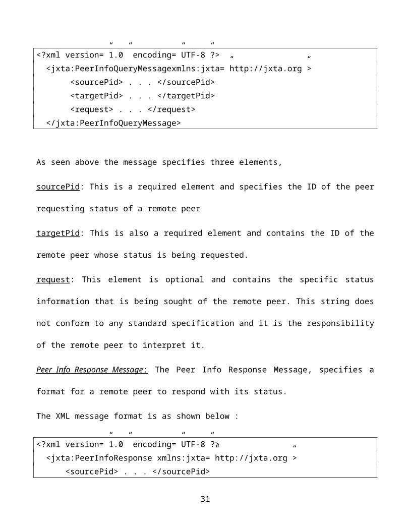
remote peer. The XML format of the message is as shown below :
<?xml version=”1.0” encoding=”UTF-8”?> <jxta:PeerInfoQueryMessagexmlns:jxta=”http://jxta.org”>
19
<sourcePid> . . . </sourcePid> <targetPid> . . . </targetPid> <request> . . . </request> </jxta:PeerInfoQueryMessage>
As seen above the message specifies three elements,
sourcePid: This is a required element and specifies the ID of the peer requesting status of a remote peer
targetPid: This is also a required element and contains the ID of the remote peer whose status is being
requested.
request: This element is optional and contains the specific status information that is being sought of the
remote peer. This string does not conform to any standard specification and it is the responsibility of the
remote peer to interpret it.
Peer Info Response Message : The Peer Info Response Message, specifies a format for a remote peer to
respond with its status.
The XML message format is as shown below :
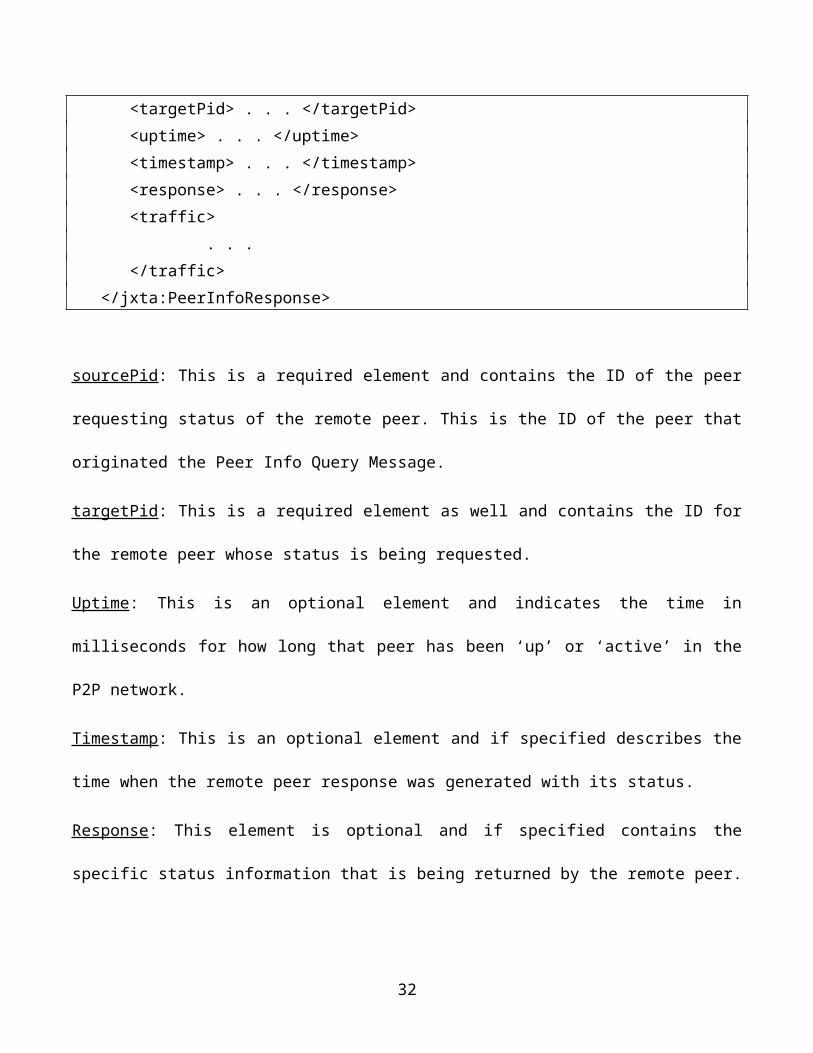
<?xml version=”1.0” encoding=”UTF-8”?> <jxta:PeerInfoResponse xmlns:jxta=”http://jxta.org”> <sourcePid> . . . </sourcePid> <targetPid> . . . </targetPid> <uptime> . . . </uptime> <timestamp> . . . </timestamp> <response> . . . </response> <traffic> . . . </traffic> </jxta:PeerInfoResponse>
20

sourcePid: This is a required element and contains the ID of the peer requesting status of the remote
peer. This is the ID of the peer that originated the Peer Info Query Message.
targetPid: This is a required element as well and contains the ID for the remote peer whose status is
being requested.
Uptime: This is an optional element and indicates the time in milliseconds for how long that peer has
been ‘up’ or ‘active’ in the P2P network.
Timestamp: This is an optional element and if specified describes the time when the remote peer
response was generated with its status.
Response: This element is optional and if specified contains the specific status information that is being
returned by the remote peer. This string does not conform to any standard specification and it is the
responsibility of the requester to interpret it.
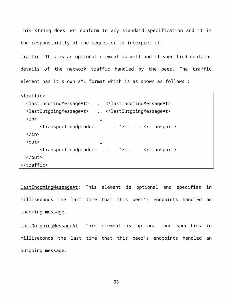
Traffic: This is an optional element as well and if specified contains details of the network traffic
handled by the peer. The traffic element has it’s own XML format which is as shown as follows :
<traffic> <lastIncomingMessageAt> . .. </lastIncomingMessageAt> <lastOutgoingMessageAt> . .. </lastOutgoingMessageAt> <in> <transport endptaddr=” . . . “> . . . </transport> </in> <out> <transport endptaddr=” . . . “> . . . </transport> </out></traffic>
lastIncomingMessageAt: This element is optional and specifies in milliseconds the last time that this
peer’s endpoints handled an incoming message.
21
lastOutgoingMessageAt: This element is optional and specifies in milliseconds the last time that this
peer’s endpoints handled an outgoing message.
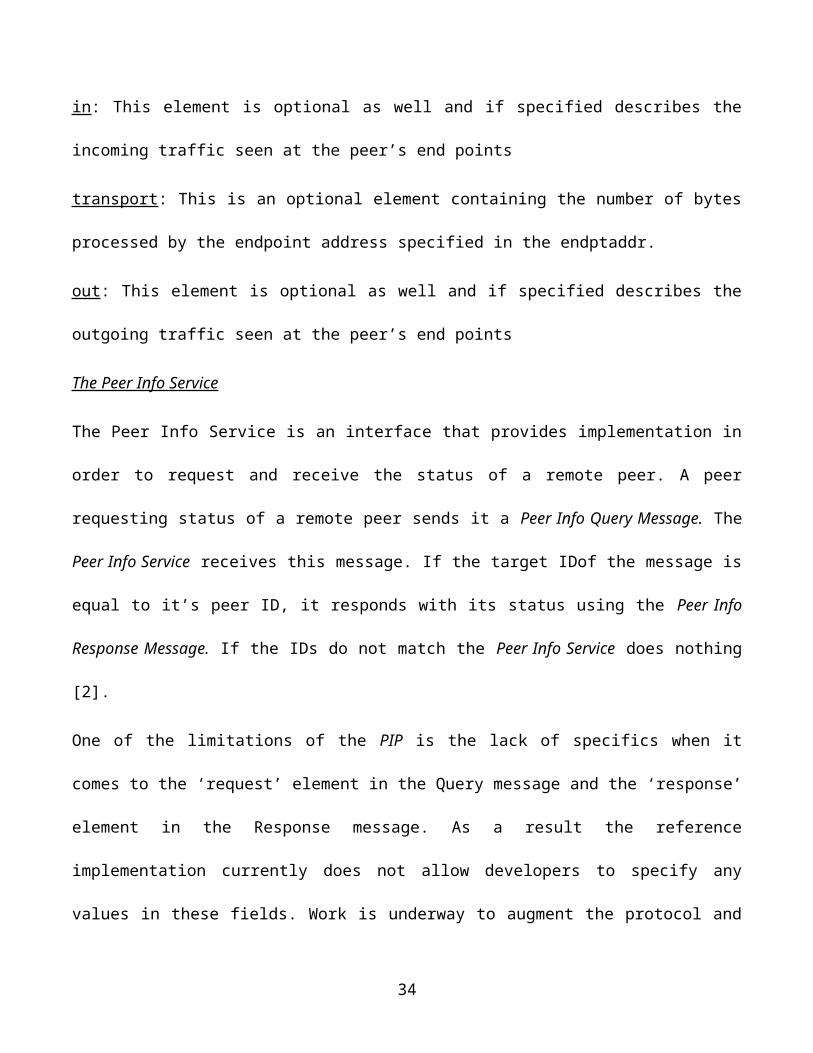
in: This element is optional as well and if specified describes the incoming traffic seen at the peer’s end
points
transport: This is an optional element containing the number of bytes processed by the endpoint address
specified in the endptaddr.
out: This element is optional as well and if specified describes the outgoing traffic seen at the peer’s end
points
The Peer Info Service
The Peer Info Service is an interface that provides implementation in order to request and receive the
status of a remote peer. A peer requesting status of a remote peer sends it a Peer Info Query Message.
The Peer Info Service receives this message. If the target IDof the message is equal to it’s peer ID, it
responds with its status using the Peer Info Response Message. If the IDs do not match the Peer Info
Service does nothing [2].
One of the limitations of the PIP is the lack of specifics when it comes to the ‘request’ element in the
Query message and the ‘response’ element in the Response message. As a result the reference
implementation currently does not allow developers to specify any values in these fields. Work is
underway to augment the protocol and define these elements in more detail so that standard handlers for
these elements may be implemented
22
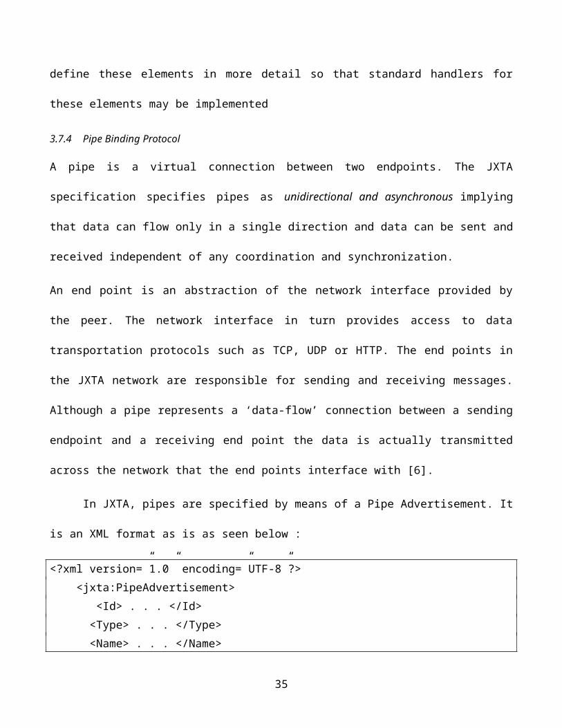
3.7.4 Pipe Binding Protocol
A pipe is a virtual connection between two endpoints. The JXTA specification specifies pipes as
unidirectional and asynchronous implying that data can flow only in a single direction and data can be
sent and received independent of any coordination and synchronization.
An end point is an abstraction of the network interface provided by the peer. The network interface in
turn provides access to data transportation protocols such as TCP, UDP or HTTP. The end points in the
JXTA network are responsible for sending and receiving messages. Although a pipe represents a ‘data-
flow’ connection between a sending endpoint and a receiving end point the data is actually transmitted
across the network that the end points interface with [6].
In JXTA, pipes are specified by means of a Pipe Advertisement. It is an XML format as is as
seen below :
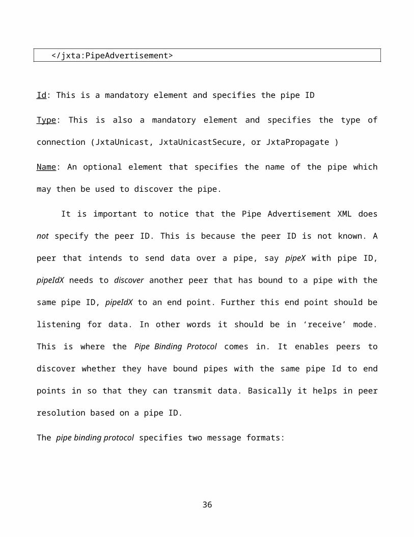
<?xml version=”1.0” encoding=”UTF-8”?> <jxta:PipeAdvertisement> <Id> . . . </Id> <Type> . . . </Type> <Name> . . . </Name> </jxta:PipeAdvertisement>
Id: This is a mandatory element and specifies the pipe ID
Type: This is also a mandatory element and specifies the type of connection (JxtaUnicast,
JxtaUnicastSecure, or JxtaPropagate )
Name: An optional element that specifies the name of the pipe which may then be used to discover the
pipe.
23
It is important to notice that the Pipe Advertisement XML does not specify the peer ID. This is
because the peer ID is not known. A peer that intends to send data over a pipe, say pipeX with pipe ID,
pipeIdX needs to discover another peer that has bound to a pipe with the same pipe ID, pipeIdX to an
end point. Further this end point should be listening for data. In other words it should be in ‘receive’
mode. This is where the Pipe Binding Protocol comes in. It enables peers to discover whether they have
bound pipes with the same pipe Id to end points in so that they can transmit data. Basically it helps in
peer resolution based on a pipe ID.
The pipe binding protocol specifies two message formats:
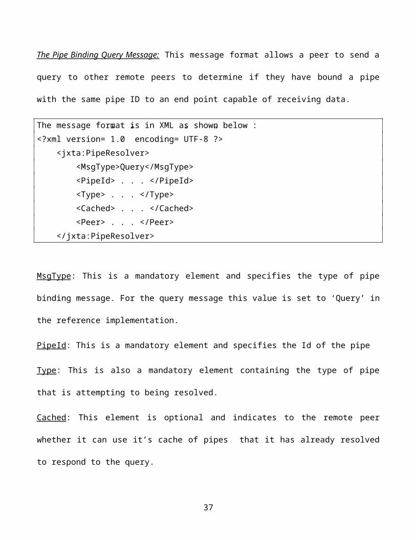
The Pipe Binding Query Message: This message format allows a peer to send a query to other remote
peers to determine if they have bound a pipe with the same pipe ID to an end point capable of receiving
data.
The message format is in XML as shown below :<?xml version=”1.0” encoding=”UTF-8”?> <jxta:PipeResolver> <MsgType>Query</MsgType> <PipeId> . . . </PipeId> <Type> . . . </Type> <Cached> . . . </Cached> <Peer> . . . </Peer> </jxta:PipeResolver>
MsgType: This is a mandatory element and specifies the type of pipe binding message. For the query
message this value is set to ‘Query’ in the reference implementation.
PipeId: This is a mandatory element and specifies the Id of the pipe
Type: This is also a mandatory element containing the type of pipe that is attempting to being resolved.
24
Cached: This element is optional and indicates to the remote peer whether it can use it’s cache of pipes
that it has already resolved to respond to the query.
Peer: According to the specs this is the peer Id that should respond. However the reference
implementation leaves this blank.
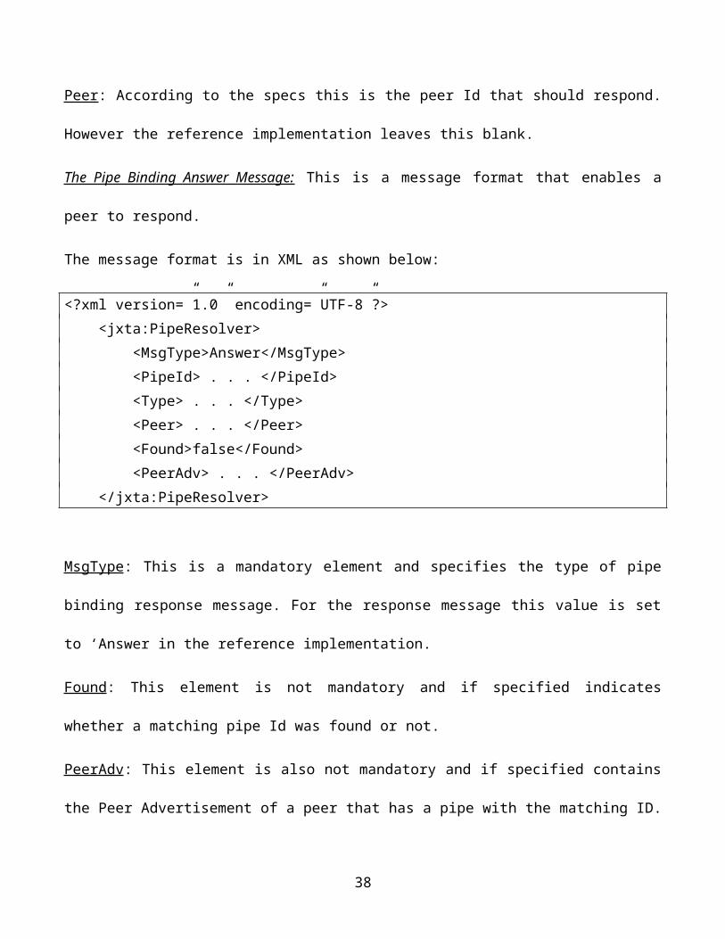
The Pipe Binding Answer Message: This is a message format that enables a peer to respond.
The message format is in XML as shown below:
<?xml version=”1.0” encoding=”UTF-8”?> <jxta:PipeResolver> <MsgType>Answer</MsgType> <PipeId> . . . </PipeId> <Type> . . . </Type> <Peer> . . . </Peer> <Found>false</Found> <PeerAdv> . . . </PeerAdv> </jxta:PipeResolver>
MsgType: This is a mandatory element and specifies the type of pipe binding response message. For the
response message this value is set to ‘Answer in the reference implementation.
Found: This element is not mandatory and if specified indicates whether a matching pipe Id was found
or not.
PeerAdv: This element is also not mandatory and if specified contains the Peer Advertisement of a peer
that has a pipe with the matching ID.
The Pipe Service: The PBP is implemented as a Pipe Service which provides the implementation
framework for creating input and output pipe objects and binding these objects to end points for data
transmission through them.
25
The following scenario illustrates a typical scenario where the PBPand Pipe Service are used :
1. A peer, say, PeerA creates an input pipe with a Pipe Advertisement.
2. Another peer, say, PeerB is interested in communicating (sending data) to PeerA using the same
pipe advertisement. Hence it sends a Pipe Binding Query Message to all of its known and
rendezvous peers.
3. Peer A receives this message over the JXTA P2P network and sends back a pipe Binding
Response Message as it has a pipe with the matching pipeId.
4. PeerB receives this response message and uses it to create an output pipe.
5. PeerB now communicates with PeerA.
In this manner we have seen how pipes may be bound to end points and then send and receive data to or
from a remote peer.
4. Example P2P Application
We now turn to an example application that will help us motivate the need for an RBAC capability in
JXTA. Let us consider a sample ‘Document Management’ application. In this application the
application programmer would like to provide the ability for individuals to create documents, allow
them to be reviewed, and publish them.
This type of application has several advantages to being implemented as a P2P application rather
than as a standard client server application. In a normal client server architecture the server would have
to maintain all the documents as well as workflow status and state information. The scalability of the
application will be limited by the scalability of the server. However in a P2P architecture, the document
is only required to ‘pass through’ the peers that need to act on it as part of the workflow. Also in a client
server architecture, since the server houses all the documents, it handles all of the workflow. However
26
in a P2P architecture the workflow is distributed amongst all the peers. As a result the security impact of
a breach on a server is much greater than the security impact of a breach on a peer.
Given that there are several advantages to using the P2P architecture the question shifts to
implementation. JXTA being standards based, cross platform, and language independent lends itself
well as an implementation technology. However, in the JXTA framework, security is based on peer
groups and can be enforced by creating secure peer groups and controlling membership into these
groups. If multiple peers are part of an application then they may all be given access to a specific peer
group. If the application requires that functionality be divided amongst the different peers based on
roles, then it puts the onus of defining roles, defining responsibilities for those roles and enforcing
system access based on those roles, on the application programmer. This can become cumbersome.
Implementing a layer over the JXTA framework that defines access to the application based on
roles alleviates the application programmer of the task and enables them to focus purely on developing
the application. This is where integrating RBAC principles with the JXTA technology provides value to
the application developer.
Going back to our sample ‘Document Management’ application, there are four roles with specific
responsibilities:
1. Author : This role is responsible for creating the document.
2. Reviewer : In this role the intention is to serve as a peer reviewer and provide feedback on
content accuracy of the document. The focus is more on semantics
3. Copy Editor : This role is responsible for ensuring accurate syntax of the document and is also
responsible for document presentation and formatting.
4. Publisher : This role is responsible for making the document available to the intended audience.
27
It then becomes the job of the developer to translate the roles into role names and responsibilities into
application specific methods. The methods may further be classified into two types, namely ‘access’
and ‘publish’. For example in an interaction between the Author and the Reviewer, the Reviewer needs
access to the document to review it and the Author then needs access to the feedback. Thus a method
‘getDocument()’ would be published by the Author and accessed by the Reviewer while a method
‘getFeedback()’ would be published by the Reviewer and accessed by the Author. Having discussed in
theory a scenario which motivates the need for an implementation of RBAC into JXTA, let us now talk
about a reference implementation that provides these capabilities.
5. Implementation of RBAC into JXTA
In this section, I discuss the reference implementation of the RBAC authorization into the JXTA
framework. I describe the technologies used as well as the design of the distributed RBAC mechanism.
5.1 Authentication vs. Authorization
Authentication is a mechanism for ensuring that a peer is who it claims to be. Authorization is a
mechanism for ensuring that a peer has access to the resources that it should have. In this
implementation, I only consider RBAC authorization and assume that all the peers have been
authenticated. Many authentication methods for JXTA already exist (primarily relying on PKI), so this
paper does not focus on re-implementing them. It should be noted that authentication is a prerequisite
for the authorization implementation.
5.2 RBAC Resource
For the purpose of this implementation, access to a resource is simple access to a method from a peer
pipe. A method is called remotely over a JXTA socket. A remote method call object will be marshaled
and demarshalled across the socket. The result will be processed on the server peer that services the role
28
and be returned to the client peer that is requesting the processing. This technique is in alignment with
current object oriented techniques [4].
6. Application Design
In this section we will go through the design of the application in detail. The section starts out with
specifics on technology decisions that have been taken. It then goes into the application overview and
some assumptions that have been made in the system.
6.1 Technology decisions
In an attempt to enforce Roles Based Access Control in a peer to peer network, I have chosen to use
XML (Extensible Markup Language) to set up the authorization configuration. Further I have chosen to
use Apache’s Commons Digester as the XML parser. In the section below I have explained why I chose
XML and the Commons Digester parser.
The choice of XML :
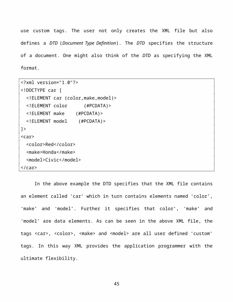
XML bears roots in SGML (Standard Generalized Markup Language). It is an extremely flexible
markup language that enables users to define and use custom tags. The user not only creates the XML
file but also defines a DTD (Document Type Definition). The DTD specifies the structure of a document.
One might also think of the DTD as specifying the XML format.
<?xml version="1.0"?><!DOCTYPE car [ <!ELEMENT car (color,make,model)> <!ELEMENT color (#PCDATA)> <!ELEMENT make (#PCDATA)> <!ELEMENT model (#PCDATA)>]><car> <color>Red</color> <make>Honda</make>
29
<model>Civic</model></car>
In the above example the DTD specifies that the XML file contains an element called ‘car’
which in turn contains elements named ‘color’, ‘make’ and ‘model’. Further it specifies that color’,
‘make’ and ‘model’ are data elements. As can be seen in the above XML file, the tags <car>, <color>,
<make> and <model> are all user defined ‘custom’ tags. In this way XML provides the application
programmer with the ultimate flexibility.
It is important to note here that XML documents might contain DTDs in them, might reference
external DTDs or may have no DTDs. If an XML document has no DTDs, the application programmer
has to programmatically indicate how they want the XML to be parsed.
XML parsers : An XML document once defined needs to be parsed. There are two types of XML
parsers :
1. DOM (Document Object Model) XML Parser: A DOM parser works by creating a
tree like hierarchical structure of the XML document. The DOM parses reads the entire XML document
into memory and creates an object-oriented hierarchical representation of the document that the
application programmer can navigate at run-time. Since the document is stored in memory, updates to
the document can be easily made. Although the DOM approach can potentially use a lot of memory,
depending on the size of the XML document, the advantage is the document contents are stored and
available during run time.
2. SAX (Simple API for XML) XML Parser: The SAX parser on the other hand is event
based. The parser scans through the XML document. When it encounters a specific tag it calls a
‘handler’ method. It is then the responsibility of the handler method to process/store the data. If the
handler does not store the data, the data is lost. Unlike the DOM parser, the SAX parser does not store
30
the document in memory. The SAX parser is more efficient from a resource utilization standpoint put it
places the onus of storing the data on the application programmer. An example of a SAX parser is the
Commons Digester parser from Apache.
The application reads the authorization configurations into data structures and user defined objects that
it can then use to enforce RBAC policies. In order to provide the application programmer with this
ability as well as for performance reasons this system uses a SAX parser.
6.2 JXTA Sockets
Although JXTA provides bidirectional pipe access, I chose the use of JXTA Sockets instead. JXTA
sockets provide a familiar sockets interface on top of JXTA and provide added performance and
reliability capabilities. However, a drawback of JXTA sockets over pipes is very low one way
throughput [8]. Creating a JXTA socket involves passing a pipe advertisement. JXTA sockets inherit
from java sockets so sending and receiving objects across the wire is more straightforward as techniques
to transfer objects over regular sockets are well known.
6.3 Application Overview
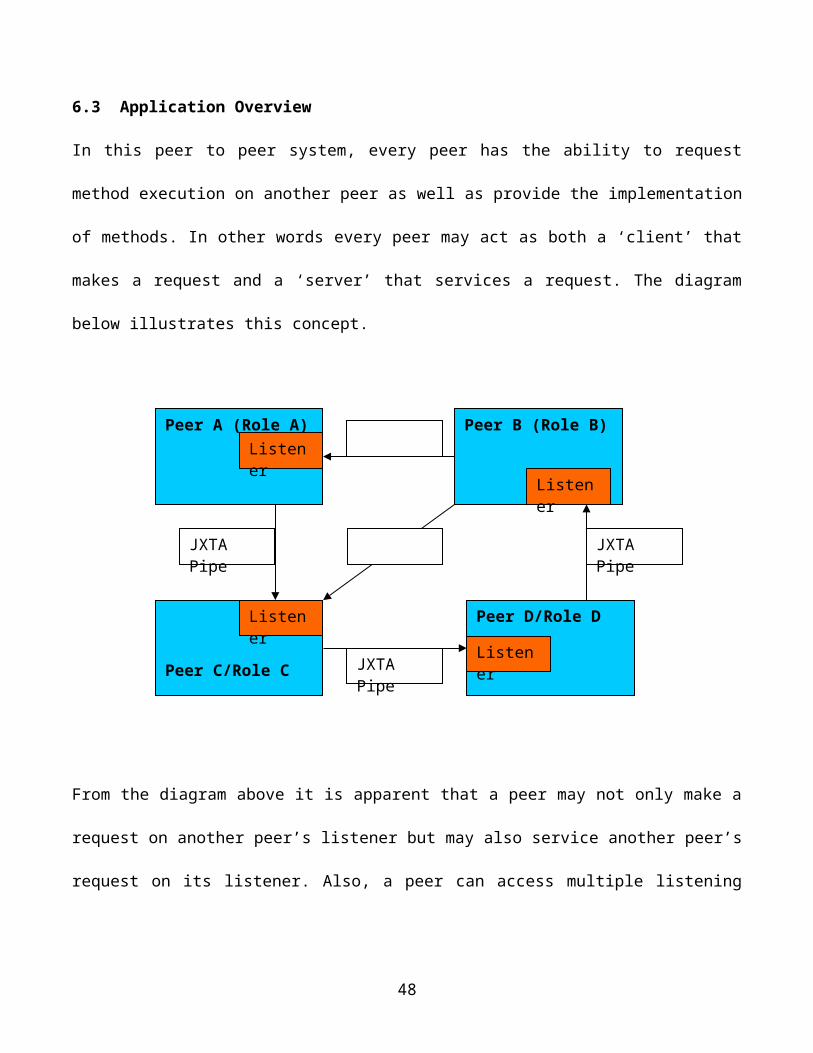
In this peer to peer system, every peer has the ability to request method execution on another peer as
well as provide the implementation of methods. In other words every peer may act as both a ‘client’ that
makes a request and a ‘server’ that services a request. The diagram below illustrates this concept.
31
From the diagram above it is apparent that a peer may not only make a request on another peer’s listener
but may also service another peer’s request on its listener. Also, a peer can access multiple listening
peers. It is worth mentioning here that this system is based on certain assumptions:
Assumptions
1. As seen in the above diagram, each peer can only belong to one role at a time.
2. During the life of the application (the running time of all peers) a peer cannot change roles. So
the role it takes on initially is the role it is assigned during the running time of the application.
3. The peers must all agree on the roles configuration and the peer/role mapping.
6.4 Detailed Design
Having gone through the application overview, this section covers the design in greater detail and takes
a closer look at what comprises an RBAC peer. Each peer may be thought of as consisting of three
32
Peer A (Role A)Listener
Peer C/Role C
Listener
Peer B (Role B)
Listener
Peer D/Role D
Listener
JXTA Pipe JXTA Pipe
JXTA Pipe
components namely the XML Engine, RBAC Engine and Execution Engine. The diagram below
illustrates this concept.
6.5 XML Engine
The XML Engine reads in the XML configuration files that are used to specify details about business
processes in the system that specific roles have access to. XML files are also used to map a peer to a
specific role. The engine then parses these XML files and stores them in data structures for use by the
peer.
Defining Roles :
The process of defining roles is three fold:
1. The application programmer should be able to define a role name
2. Further they should be able to define the methods that a specific role implements. In the case of
this application, it is called ‘publish methods’
33
Peer
XML engine (Define roles, parse the XML file and store it)
Execution Engine(Executes methods and returns results )
RBAC Engine(enforces security policy)
3. Lastly, they should be able to specify methods than a role can call. In the case of this application
it is called ‘access methods’
In this application the roles are defined in a file called RolesConfiguration.xml. The XML parser of
choice is the Apache Common’s Digester that is used to parse this file.
Below is a sample RolesConfiguration.xml file.
<?xml version="1.0"?><RolesConfig>
<Role> <rolename>RoleA</rolename> <publishmethod>add</publishmethod>
<publishmethod>multiply</publishmethod> <accessmethod>subtract</accessmethod>
</Role> <Role> <rolename>RoleB</rolename> <publishmethod>subtract</publishmethod> <publishmethod>divide</publishmethod> <accessmethod>add</accessmethod> <accessmethod>mulitply</accessmethod> </Role></RolesConfig>
In this application there are two roles and four methods. The two roles are Role A and Role B. The four
methods are ‘add’, ‘subtract’, ‘multiply’ and ‘divide’. As Role A, a peer provides implementations for
methods add and multiply and has the permissions to execute method subtract. On the other hand as
Role B, a peer provides implementations for methods subtract and divide and has the permissions to
execute methods add and multiply.
The code snippet that uses the Commons Digester to parse the XML file is as follows,
34
1. Digester digester = new Digester()2. digester.setValidating( false )3. digester.addObjectCreate( "RolesConfig", RolesConfig.class );4. digester.addObjectCreate( "RolesConfig/Role", Role.class );5. digester.addBeanPropertySetter( "RolesConfig/Role/rolename", "roleName" );6. digester.addBeanPropertySetter( "RolesConfig/Role/accessmethod", "accessMethod" );7. digester.addBeanPropertySetter( "RolesConfig/Role/publishmethod", "publishMethod" );8. digester.addSetNext( "RolesConfig/Role", "addRole" );
In line 1, an instance of the Digester is instantiated. Since RolesConfiguration.xml does not use a DTD
the Digester needs to be made aware of the same. This is done by setting the setValidating method to
false in line 2. The next step is to specify the XML patterns and the associated rules. In line 3, the
ObjectCreateRule creates an instance of class RolesConfig and pushes it onto the stack. In line 4, the
ObjectCreateRule creates an instance of class Role and pushes it onto the stack. In line 5 the
BeanPropertySetterRule specifies that a setter method should be called when the pattern
RolesConfig/Role/rolename is encountered. Specifically, that setter method setRoleName(String
paramName) will be called. It is important to note here that the Digester follows the rules of
introspection when using the BeanPropertySetterRule. Thus a getter needs to be specified as well. If a
getter ‘public String getRoleName() {return paramName}’ is not specified in Role.java, this rule will
not trigger. The code in lines 6 and 7 perform similar actions to what is done in line 5. In line 8, the rule
SetNextRule is utilized. This rule pops the object on top of the parse stack and passes it to the named
method, ‘addRole’ on the object below it which in this case is ‘RolesConfig’. The method ‘addRole’
that is defined in the RolesConfig object, adds the recently created Role object (along with the role
name, access methods and publish methods) to a vector of Role objects that is stored in the RolesConfig
35
object. Kindly refer to the Appendix on the code for more details on the implementation of the Role and
RoleConfig classes.
Define mapping between a Peer and a Role :
Apart from defining the roles, there needs to be a mapping specified between a Peer name and it’s Role
name. This will also be done using XML. The file is called PeerRoleMapping.xml and also uses the
Commons Digester to parse this file and store the mapping as a hash.
Below is a sample PeerRoleMapping.xml file:
<?xml version="1.0"?><PeerRoleMapping> <Peer> <peername>peer1</peername> <rolename>RoleA</rolename> </Peer> <Peer> <peername>peer2</peername> <rolename>RoleB</rolename> </Peer></PeerRoleMapping>
6.6 RBAC engine
The RBAC engine enforces the security policy for roles based access. Following is the algorithm that is
used to ensure proper access to methods based on roles.
1. When a peer is started in JXTA, it is given a peer name.
2. During initialization every peer reads the two above mentioned XML files,
PeerRoleMapping.xml and RolesConfiguration.xml. The purpose of defining both these XML
36
files in all the peers is to ensure that all the peers are implementing the same security policy by
containing similar content.
3. Both the XML files are parsed by the Digester into specific data structures. These data structures
are then wrapped in to objects. When a Peer A sends a method execution request to a Peer B, it
also sends it’s version of the XML configuration files. (As mentioned above, this is done by
sending the objects that contain the data structures resulting from the XML parser). Peer B
checks to ensure that the contents of the XML files that it has corresponds with those defined in
Peer A. If the contents vary, Peer B throws a Security Exception. In this manner a ‘malicious’
peer that perhaps tries to ‘alter’ the role assigned to a particular peer is ‘caught’ and is not
allowed to execute methods on other peers in the peer to peer network. This is Phase I of the
Security Engine.
4. If however the contents of the two XML configuration files on both peers are the same then the
security engine proceeds to the second phase. It processes the request for a method execution.
The first part of this request contains the peer name of the requester, which in this case is Peer
A. Peer B obtains the role for Peer A from its data structure (potentially a hashmap). Let us say
that the role for Peer A is Role A. The security engine checks against the definition in
RolesConfiguration.xml to see if Role A indeed has the permissions to ‘access’ the method it
seeks to execute. If the security engine finds that as Role A, Peer A indeed cannot access the
method it seeks to execute, it throws a Security Exception.
5. If however Peer A does have the permissions to ‘access’ the method it wishes to execute the
security engine proceeds to Phase III of it’s security policy. In this phase Peer B obtains its role
from the PeerRole hash and then verifies that it indeed ‘publishes’ the method that Peer A is
37
seeking to ‘access’/execute. If Peer B does not ‘publish’ or provide an implementation of that
specific method, it throws a Security Exception.
6. If on the other hand Peer B does have the permissions to provide an implementation of that
method, then it executes that method and returns the results to Peer A.
6.7 Execution Engine
The execution engine is a set of classes that provide the implementation of the business logic. These
classes also use JXTA protocols and sockets to communicate between peers transmitting method
execution requests between each other and sending results back. The execution engine utilizes the XML
engine and the Security engine. It consists of the following primary classes:
Peer.java : This class is a core class of the application. A Peer could request method execution as well
as service a request for a method execution (‘equivalent’ functionalities). Peer.java does exactly this. It
acts as a ‘client’ in the sense it requests method execution. It does this by :
Starts a JXTA Peer Group
Creates a Pipe Advertisement
Initiates a client socket connection.
It is important to note here that if a Peer with a particular role name requests access to a method that it
publishes, then the method is executed locally other wise it is executed remotely. Let us look at this in
the form of an algorithm.
1. Start up a new JXTA instance by creating a JXTA net peer group. Obtain the peer name from
the net peer group. Look in the hashmap that contains a mapping of peer names and role names
(created from PeerRolesMapping.xml) and obtain the role name for this peer name.
2. Initiate a method execution call.
38
3. Determine whether this method is being published by ‘my role’. That is, if a role requesting
access to the method is indeed the one that publishes it. If so execute the method locally and skip
to Step 7.
4. If not, then determine then determine the role name that publishes this method. This is obtained
from the data structure created from RolesConfiguration.xml. Create a Pipe Advertisement based
on an advertisement file called <rolename>.adv file that is specific to the role that publishes the
method.
5. Initiate a client socket connection using the net peer group and the pipe advertisement.
6. Issue a method call to the remote peer. The actual method call and arguments along with the
XML configurations are wrapped in an object which are then marshaled or serialized and sent
over the socket. The remote peer executes the function, serializes the request and sends it back to
the requesting peer which then deserializes it.
7. Display the results of execution.
In addition to containing the code to request a method call, Peer.java also starts up the listener thread
which services the request.
Also, Peer.java provides the business logic implementation for this application, namely, the
implementation of functions ‘add’, ‘subtract’, ‘multiply’ and ‘divide’
Object Marshalling and Demarshalling :
We discussed object serialization. Let us examine this in a little more detail. Serialization is the
mechanism whereby an object is transformed into a byte stream. This stream of bytes may then be sent
across a socket. It is important to note that object serialization is not always done to send objects across
sockets. Objects that have been serialized may also be persisted (stored in a file or database).
39
Any time that an application requires a long-lasting and reliable connection between two remote
peers there is an inherent point of failure built in. The longer the connection needs to last, or the higher
the communication bandwidth the connection requires, the more likely the application is to occasionally
break down. The benefit of serializing objects is that since a copy is sent over to the remote peer, there
is now bandwidth or network utilization during the execution of business logic. Typically business logic
processing involves complex code and is intensive on resources. This can all happen ‘locally’ and
contained within the peer that is servicing the request. Once the results are obtained they are serialized
and sent back through the socket for the client to deserialize and interpret. In Java, object serialization is
achieved by implementing the ‘Serializable’ interface. In our application Peer.java implements the
Serializable interface.
ListenerThread.java : This class services a request for method execution. It is instantiated by Peer.java
and in the process of doing so is passed the name of the Net Peer Group used by the client peer. As a
separate thread of execution this class starts up a JXTA Pipe Advertisement by using the advertisement
file that corresponds with its role. Let us illustrate this by means of an example:
Let us say we have two peers, PeerA with role, RoleA and PeerB with role RoleB. As seen in the
above XML file RoleA can request access to method subtract. However subtract is published by RoleB .
Thus PeerA determines that its role, RoleA does not publish subtract. Subtract is published by PeerB.
Hence it proceeds to create a Pipe Advertisement using advertisement file RoleB.adv. It is important to
note here that the advertisement file used by the requesting peer is the <rolename>.adv file of the peer
that publishes the method. When the method request then propagates to Peer B, it establishes that it does
publish subtract. It therefore creates an advertisement with the advertisement file that corresponds to its
role name which will is be RoleB.adv. In this manner the two peers communicate over the same socket.
40
It then uses this pipe advertisement and the name of the net peer group used by the client to create a
JXTA server socket. The server socket, receives the data processes it and sends the results back using
object serialization and deserialization.
6.8 Class Diagram
Having explained the interaction amongst the three engines let us examine the static interaction of all
the classes in the system.
41
6.9 Sequence diagrams
The dynamic interaction of the system is depicted in the form of sequence diagrams.
6.9.1 Local peer execution
The first sequence diagram depicts the execution sequence of a Peer that requests a method that is
executed locally. In the figure below the requesting peer’s role name is the same as the role name that
publishes the method, hence the execution happens locally.
42
6.9.2 Remote Execution: Client Sequence
This second sequence diagram depicts the client scenario wherein the method execution call goes over a
socket to a remote peer. The requesting peer writes the remote method call to the socket and then reads
the results of the execution from the socket. The execution sequence that happens at the server end is
not depicted here and is depicted in the next sequence diagram .
6.9.3 Remote Execution: Server Sequence
43
This next sequence diagram depicts the server side execution sequence when a method is executed by a
remote peer. The RBAC security policies are enforced at this remote peer. However this is not depicted
in this sequence diagram. The next sequence diagram depicts the RBAC policy enforcement.
44
6.9.4 RBAC security policy enforcement
Note how in the previous sequence diagram a note states ‘execute method if security checks pass’. The
below sequence diagram depicts these security checks and policy enforcements in detail:
45
6.10 Tests and Results
Tests on the system have been conducted based on the following versions of the configuration files:
The PeerRoleMapping.xml used was :
<?xml version="1.0"?><PeerRoleMapping> <Peer> <peername>peer1</peername> <rolename>RoleA</rolename> </Peer> <Peer> <peername>peer2</peername> <rolename>RoleB</rolename> </Peer></PeerRoleMapping>
The RolesConfiguration.xml file used was
<?xml version="1.0"?><RolesConfig>
<Role> <rolename>RoleA</rolename> <publishmethod>add</publishmethod>
<publishmethod>multiply</publishmethod> <accessmethod>subtract</accessmethod>
</Role> <Role> <rolename>RoleB</rolename> <publishmethod>subtract</publishmethod> <publishmethod>divide</publishmethod> <accessmethod>add</accessmethod> <accessmethod>mulitply</accessmethod> </Role></RolesConfig>
46
Requesting Peer
Requesting Role Name
Access Method
Expected result Actual result Test Status
Peer1 RoleA add RoleA does not have permissions to access method add. Method add is not executed
Same as expected Pass
Peer 1 RoleA subtract RoleA has permissions to access method subtract. Peer2 with RoleB services the request as RoleB publishes subtract.
Same as expected Pass
Peer1 RoleA multiply RoleA does not have permissions to access method multiply. Method multiply is not executed
Same as expected Pass
Peer 1 RoleA divide RoleA does not have permissions to access method divide. Method divide is not executed
Same as expected Pass
Peer2 RoleB add RoleB has permissions to access method add. Peer1 with RoleA services the request as RoleA publishes add.
Same as expected Pass
Peer2 RoleB subtract RoleB does not have permissions to access method subtract. Method subtract is not executed
Same as expected Pass
Peer2 RoleB multiply RoleB has permissions to access method multiply. Peer1 with RoleA services the request as RoleA publishes multiply.
Same as expected Pass
Peer2 RoleB divide RoleB does not have permissions to access
Same as expected Pass
47
method divide. Method divide is not executed
7. Conclusion
I have discussed a technique which establishes a P2P RBAC mechanism. I then described a reference
implementation in the JXTA framework. Finally, I demonstrated a mathematical application which
utilizes the reference implementation and provides a testing mechanism. Now, an application developer
will have the ability to write distributed P2P applications without having to worry about ensuring that
the proper authorization is occurring. The developer simply needs to specify two XML configuration
files and then write the appropriate code for each role and the RBAC implementation will enforce the
security policy. If utilized effectively, this technique should lead to more robust and secure P2P
applications in the future.
8. Future Work
Enhancements to the infrastructure that would significantly increase its capabilities are:
Multiple peers implementing the same role: The ability to have a multiple peers implementing the same
role would be desirable as it could both add to the increased performance and availability of the system.
The peer that is used could be load balanced across all the peers that implement the role that is needed.
This could be accomplished by having the peer that is attempting to connect to a remote peer simply
randomly choose the peer from the list of remote peers that are servicing the role. Also, if a peer were to
go down, another peer that is servicing the same role could be used.
A peer changing roles: The ability to have a single peer change roles at run time. This would allow the
application to be written such that a peer need only be in a role for the amount of time that is needs to.
48

This would better support the concept of least privilege. However, in this scenario, all peers would need
to agree of the change and update their roles, otherwise there could possibly be security issues.
Role Hierarchies: The ability to have a hierarchical organization for roles would provide a flexible way
for roles to be structured. For example, RoleA could ‘inherit’ from RoleB. In this case, all the access
and publish methods from RoleB would be inherited from RoleA.
Java Reference Implementation: As the current RBAC reference implementation uses the Java JXTA
reference implementation, it currently will only work for those application developers that are
programming in Java. To be used in other programming languages, this reference implantation would
need to be ported to another language that provides an implantation for JXTA.
Performance Improvements: The performance of the system for large numbers and size of objects as
well as large numbers of peers has not been completed. If this study were to be done, improvements
could be made to overcome any performance bottlenecks that were identified. Depending on workload,
it may make sense to utilize bidirectional pipes over JXTA sockets [8].
49
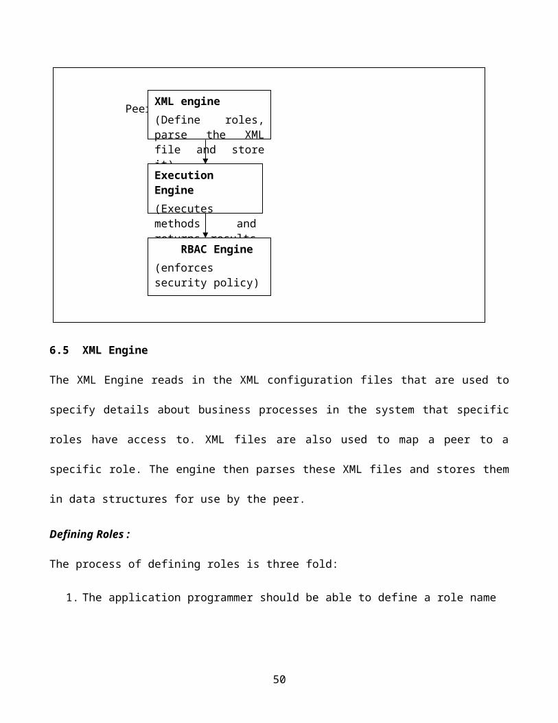
9. References
[1] Gong, L., Oaks S., Traversat B., JXTA in a Nutshell.
[2] JXTA website. http://www.jxta.org
[3] R. S. Sandhu, E.J. Coyne, H.L. Feinstein, C.E. Youman, "Role-Based Access Control Models",
IEEE Computer 29(2): 38-47, IEEE Press, 1996
[4] J. Barkley, "Implementing Role Based Access Control Using Object Technology", First ACM
Workshop on Role-Based Access Control (1995).
[5] Joon S. Park and Junseok Hwang. Role-Based Access Control for Collaborative Enterprise in Peer-
to-Peer Computing Environment. 8th ACM Symposium on Access Control Models and
Technologies, Como, Italy, June 2-3, 2003.
[6] Wilson, B. JXTA http://www.brendonwilson.com/projects/jxta/
[7] Wikopedia website. http://en.wikipedia.org/wiki/Peer-to-peer
[8] Emir Halepovic, Ralph Deters. JXTA Messaging: Analysis of Feature-Performance
Tradeoffs,
Department of Computer Science University of Saskatchewan, Saskatoon SK
Canada
50