process control a physical properties of the streams. in ... control... · process control /i...
TRANSCRIPT
3 PROCESS CONTROL
/I processes are subject to disturbances that tend to change operating conditions, compositions, and physical properties of the streams. In order to A minimize the ill effects that could result from such
disturbances, chemical plants are implemented with substantial amounts of instrumentation and automatic control equipment. In critical cases and in especially large plants, moreover, the instrumentation is computer monitored for convenience, safety, and optimization.
For example, a typical billion lb/yr ethylene plant may have 600 control loops with control valves and 400 interacting loops with a cost of about $6 million. (Skrokov, 1980, pp. 13, 49; see Sec. 3.1); the computer implementation of this control system will cost another $3 million. Figure 3.1 shows the control system of an ethylene fractionator which has 12 input signals to the computer and four outgoing reset signals to flow controllers.
must represented by a mathematical model. Ideally, each element of a dynamic process, for example, a reflux drum or an individual tray of a fractionator, is represented by differential equations based on material and energy balances, transfer rates, stage efficiencies, phase equilibrium relations, etc., as well as the parameters of sensing devices, control valves, and control instruments. The process as a whole then is equivalent to a system of ordinary and partial differential equations involving certain independent and dependent variables. When the values of the independent variables are specified or measured, corresponding values of the others are found by computation, and the information is transmitted to the control instruments. For example, if the temperature, composition, and flow rate of the feed to a fractionator are perturbed, the computer will determine the other flows and the heat balance required to maintain constant overhead purity. Economic factors also can be incorporated in process models; then the computer can be made to optimize the operation continually.
models usually are adequate. In distillation, for instance, the Underwood-Fenske-Gilliland model with constant relative volatilities and a Simplified enthalpy balance may be preferred to a full-fledged tray-by-tray calculation every time there is a perturbation. In control situations, the demand for speed of response may not be realizable with an overly elaborate mathematical system. Moreover, in practice not all disturbances are measurable, and the process characteristics are not known exactly. Accordingly feedforward control is supplemented in most instances with feedback. In a welldesigned system (Shinskey, 1984, p. 186) typically 90%
In order for a process to be controllable by machine, it
For control purposes, somewhat simplified mathematical
of the corrective action is provided by feed forward and 10% by feedback with the result that the integrated error is reduced by a factor of 10.
A major feature of many modern control systems is composition control which has become possible with the development of fast and accurate on-line analyzers. Figure 3.2 shows that 10 analyzers are used for control of ethylene composition in this plant within the purities shown. High speed on-line gas chromatographs have analysis times of 30- 120 sec and are capable of measuring several components simultaneously with a sensitivity in the parts/million range. Mass spectrometers are faster, more stable, and easier to maintain but are not sensitive in the ppm range. Any one instrument can be hooked up to a halfdozen or so sample ports, but, of course, at the expense of time lag for controller response. lnfrared and NMR spectrometers also are feasible for on-line analysis. Less costly but also less specific analyzers are available for measuring physical properties such as refractive index and others that have been calibrated against mixture composition or product purity.
The development of a mathematical model, even a simplified one that is feasible for control purposes, takes a major effort and is well beyond the scope of the brief treatment of process control that can be attempted here. What will be given is examples of control loops for the common kinds of equipment and operations. Primarily these are feedback arrangements, but, as mentioned earlier, feedback devices usually are necessary supplements in primarily feedforward situations.
When processes are subject only to slow and small perturbations, conventional feedback PlD controllers usually are adequate with set points and instrument characteristics fine-tuned in the field. As an example, two modes of control of a heat exchange process are shown in Figure 3.8 where the objective is to maintain constant outlet temperature by exchanging process heat with a heat transfer medium. Part (a) has a feedback controller which goes into action when a deviation from the preset temperature occurs and attempts to restore the set point. lnevitably some oscillation of the outlet temperature will be generated that will persist for some time and may never die down if perturbations of the inlet condition occur often enough. In the operation of the feedforward control of part (b), the flow rate and temperature of the process input are continually signalled to a computer which then finds the flow rate of heat transfer medium required to maintain constant process outlet temperature and adjusts the flow control valve appropriately. Temperature oscillation amplitude and duration will be much less in this mode.
~ ~~~
3.1. FEEDBACK CONTROL
In feedback control, after an offset of the controlled variable from a preset value has been generated, the controller acts to eliminate or reduce the offset. Usually there is produced an oscillation in the value of the controlled variable whose amplitude, period, damping and permanent offset depend on the nature of the system and the
mode of action of the controller. The usual controllers provide one, two, or three of these modes of corrective action:
1. Proportional, in which the corrective action is proportional to
2. Integral, in which the corrective action at time t is proportional the error signal.
to the integral of the error up to that time.
39

40 PROCESS CONTROL
FEED
TYPICAL ETHYLENE SPECIFICATIONS
Ethylene 99.95% weight Methane Ethane
less than 500 ppm mol. % less than 500 ppm mol. %
HEAT t EXCHANGER
+r DEMETHANlZER
METHYLACETY- LENES 8 PROPY- LENE REMOVAL RECYCLE
PROPANE
DEPROPANIZER PROPYLENE SPLITTER
Figore 3.2. Flowsketch of an olefins plant and specifications of the ethylene product. AR designates a composition analyzer and controller (after Skrokov (Ed. ) , Mini- and Microcomputer Control in Industrial Processes, Van NostrandlReinhold, New York, 1980).

3.1. FEEDBACK CONTROL 41
4
5
3. Derivative, in which the corrective action is proportional to the
The relation between the change in output m - m, and input e signals accordingly is represented by
rate at which the error is being generated.
Praprtonal integral 4 3 - 66 30 0.37 0
lnlegral - 35 - 210 100 069 0
Just how these modes of action are achieved in relatively inexpensive pneumatic or electrical devices is explained in books on control instruments, for example, that of Considine (Process Instruments and Controls Handbook, Sec. 17, 1974). The low prices and considerable flexibility of PID controllers make them the dominant types in use, and have discouraged the development of possibly superior types, particularly as one-shot deals which would be the usual case in process plants. Any desired mode of action can be simulated by a computer, but at a price.
A capsule summary of the merits of the three kinds of corrective action can be made. The proportional action is rapid but has a permanent offset that increases as the action speeds up. The addition of integral action reduces or entirely eliminates the offset but has a more sluggish response. The further addition of derivative action speeds up the correction. The action of a three-mode PID controller can be made rapid and without offset. These effects are illustrated in Figure 3.3 for a process subjected to a unit step upset, in this case a change in the pressure of the control air. The ordinate is the ratio of the displacements of the response and upset from the set point.
The reason for a permanent offset with a proportional con- troller can be explained with an example. Suppose the tempera- ture of a reactor is being controlled with a pneumatic system. At the set point, say the valve is 50% open and the flow rate
Time. sec
Figure 3.3. Response of various modes of control to step input (Eckman, Automatic Process Control, Wiley, New York, 1958).
of cooling water is fixed accordingly. Suppose the heat load is doubled suddenly because of an increase in the reactor contents. At steady state the valve will remain 50% open so that the water flow rate also will remain as before. Because of the greater rate of heat evolution, however, the temperature will rise to a higher but still steady value. On the other hand, the corrective action of an integral controller depends on displacement of the temperature from the original set point, so that this mode of control will restore the original temperature.
The constants K,, Ki, and Kd are settings of the instrument. When the controller is hooked up to the process, the settings appropriate to a desired quality of control depend on the inertia (capacitance) and various response times of the system, and they can be determined by field tests. The method of Ziegler and Nichols used in Example 3.1 is based on step response of a damped system and provides at least approximate values of instrument settings which can be further fine-tuned in the field.
The kinds of controllers suitable for the common variables may be stated briefly:
Variable Controller
Flow and liquid pressure PI
Liquid level P or PI Temperature PI D Composition P, PI, PID
Gas pressure P
Derivative control is sensitive to noise that is made up of random higher frequency perturbations, such as splashing and turbulence generated by inflow in the case of liquid level control in a vessel, so that it is not satisfactory in such situations. The variety of composition controllers arises because of the variety of composition analyzers or detectors.
Many corrective actions ultimately adjust a flow rate, for instance, temperature control by adjusting the flow of a heat transfer medium or pressure by regulating the flow of an effluent stream. A control unit thus consists of a detector, for example, a thermocouple, a transmitter, the control instrument itself, and a control valve. The natures, sensitivities, response speeds, and locations of these devices, together with the inertia or capacity of the process equipment, comprise the body of what is to be taken into account when designing the control system. In the following pages will be described only general characteristics of the major kinds of control systems that are being used in process plants. Details and criteria for choice between possible alternates must be sought elsewhere. The practical aspects of this subject are treated, for example, in the References at the end of this chapter.
SYMBOLS
On working flowsheets the detectors, transmitters, and controllers are identified individually by appropriate letters and serial numbers in circles. Control valves are identified by the letters CV- followed by a serial number. When the intent is to show only in general the kind of control system, no special symbol is used for detectors, but simply a point of contact of the signal line with the equipment or process line. Transmitters are devices that convert the measured variable into air pressure for pneumatic controllers or units appropriate for electrical controllers. Temperature, for instance, may be detected with thermocouples or electrical resistance or height of a liquid column or radiant flux, etc., but the controller can accept only pneumatic or electrical signals depending on its type. When the nature of the transmitter is clear, it may be represented by an encircled cross or left out entirely. For clarity, the flowsheet can include only the most essential information. In an actual design

42 PROCESS CONTROL
EXAMPLE 3.1 Constants of PID Controllers from Response Curves to a Step Input
The method of Ziegler and Nichols [Trans ASME, (Dec. 1941)j will be used. The example is that of Tyner and May (Process Engineering Control, Ronald, New York, 1967). The response to a change of 2 psi on the diaphragm of the control valve is shown. The full range of control pressure is from 3 to 15psi, a difference of 12psi, and the range of temperature is from 100 to 200"F, a difference of 100°F. Evaluate the % displacement of pressure as
Am = 100(2/12) = 16.7%.
From the curve, the slope at the inflection point is
R = 17.5/100(7.8 - 2.4) = 3.24%/min,
and the apparent time delay is the intercept on the abscissa,
L = 2.40 min.
The values of the constants for the several kinds of controllers are Proportional: 100/Kp = % PB = 100RL/Am = 100(3.24)(2.4)/
16.7 = 46.6%. Proportional-integral: % PB = llORL/Am = 51.2%
Ki = L10.3 = 8 min
Proportional-integral-derivative :
% PB = 83RLlAm = 38.6%, Ki= 2L = 4.8 min, Kd = 0.5L = 1.2 min.
These are approximate instrument settings, and may need to be adjusted in process. PB is proportional band.
A recent improvement of the Ziegler-Nichols method due to Yuwana and Seborg [AZChE J . 28, 434 (1982)l is calculator programmed by Jutan and Rodriguez [Chem. Eng. 91(18), 69-73 (Sep. 3, 1984)].
Time (rnin) ---+
case, details of detectors and transmitters as well as all other elements of a control system are summarized on instrument specification forms. The simplified coding used in this chapter is summarized on Figure 3.4.
CASCADE (RESET) CONTROL
Some control situations require interacting controllers. On Figure 3.19(d), for instance, a composition controller regulates the setpoint of the temperature controller of a reactor and on Figure 3.15(g) the set point of the reflux flow rate is regulated by composition or temperature control. Composite systems made up of regions that respond with varying degrees of speed or sluggishness are advantageously equipped with cascade control. In the reactor of Figure 3.19(b), the temperature 'IT-1 of the vessel contents responds only slowly to changes in flow rate of the heat transfer medium, but the temperature 'IT-2 of the HTM leaving the cooling coil is comparatively sensitive to the flow rate. Accordingly, controller TC-2 is allowed to adjust the setpoint of the primary controller TC-1 with an overall improvement in control of the reactor temperature. The controller being reset is identified on flowsheets.
3.2. INDIVIDUAL PROCESS VARIABLES
The variables that need to be controlled in chemical processing are temperature, pressure, liquid level, flow rate, flow ratio, com- position, and certain physical properties whose magnitudes may be influenced by some of the other variables, for instance, viscosity, vapor pressure, refractive index, etc. When the temperature and pressure are fixed, such properties are measures of composition which may be known exactly upon calibration. Examples of control
of individual variables are shown in the rest of this chapter with the various equipment (say pumps or compressors) and processes (say distillation or refrigeration) and on the earlier flowsketches of this and the preceding chapters, but some general statements also can be made here. Most control actions ultimately depend on regulation of a flow rate with a valve.
TEMPERATURE
Temperature is regulated by heat exchange with a heat transfer medium (HTM). The flow rate of the HTM may be adjusted, or the condensing pressure of steam or other vapor, or the amount of heat transfer surface exposed to condensing vapor may be regulated by flooding with condensate, which always has a much lower heat transfer coefficient than that of condensing vapor. In a reacting system of appropriate vapor pressure, a boiling temperature at some desired value can be maintained by refluxing at the proper controlled pressure. Although examples of temperature control appear throughout this chapter, the main emphasis is in the section on heat exchangers.
PRESSURE
Pressure is controlled by regulating the flow of effluent from the vessel. The effluent may be the process stream itself or a non- condensable gas that is generated by the system or supplied for blanketing purposes. The system also may be made to float on the pressure of the blanketing gas supply. Control of the rate of condensation of the effluent by allowing the heat transfer surface to flood partially is a common method of regulating pressure in fractionation systems. Throttling a main effluent vapor line usually is not done because of the expense of large control valves. Figure 3.5 shows vacuum production and control with steam jet ejectors.

3.3. EQUIPMENT CONTROL 43
00 0
Analysis (composition) controller, transmitter
Differential pressure controller, transmitter
Flow rate controller, transmitter
Liquid level controller, transmitter
Pressure controller, transmitter
Temperature controller, transmitter
General symbol for transmitter
Control valve
Signal line, pneumatic or electrical
Point of detection
Figure 3.4. Symbols for control elements to be used on flowsheets. Instrument Society of America (ISA) publication no. S51.5 is devoted to process instrumentation terminology.
LEVEL OF LIQUID
Level of liquid in a vessel often is maintained by permanent or adjustable built-in weirs for the effluent, notably on the trays of fractionators, extractors, etc., and in reactors and drums. Any desired adjustments of weir height, however, can be made only on shutdown. Control of the flow rate of effluent (sometimes of the input) is the most common other method of level control. Liquid levels often are disturbed by splashing or flow turbulence, so that rather sluggish controllers are used for this service. Conceivably, a level could be controlled by forcing effluent through an opening of fixed size with a controlled pressure, but there do not appear to be many such applications. Continual control of the weight of a vessel and its contents is another control method that is not used often. Figure 3.6 is devoted to level control.
FLOW RATE
A rate of flow is commonly measured by differential pressure across an orifice, but many other devices also are used on occasion. Simultaneous measurements of temperature and pressure allow the flow measurement to be known in mass units. Direct mass flow
meters also are available. The flow measurement is transmitted to a controller which then adjusts the opening of a control valve so as to maintain the desired condition.
FLOW OF SOLIDS
Except for continuous weighing, control of the flow of solids is less precise than that of fluids. Several devices used for control of feed rates are shown schematically in Figure 3.7. They all employ variable speed drives and are individually calibrated to relate speed and flow rate. Ordinarily these devices are in effect manually set, but if the solid material is being fed to a reactor, some property of the mixture could be used for feed back control. The continuous belt weigher is capable ordinarily of fl% accuracy and even f0.1% when necessary. For processes such as neutralizations with lime, addition of the solid to process in slurry form is acceptable. The slurry is prepared as a batch of definite concentration and charged with a pump under flow control, often with a diaphragm pump whose stroke can be put under feedback control. For some applications it is adequate or necessary to feed weighed amounts of solids to a process on a timed basis.
FLOW RATIO
Flow ratio control is essential in processes such as fuel-air mixing, blending, and reactor feed systems. In a two-stream process, for example, each stream will have its own controller, but the signal from the primary controller will go to a ratio control device which adjusts the set point of the other controller. Figure 3.17(a) is an example. Construction of the ratioing device may be an adjustable mechanical linkage or may be entirely pneumatic or electronic. In other two-stream operations, the flow rate of the secondary stream may be controlled by some property of the combined stream, temperature in the case of fuel-air systems or composition or some physical property indicative of the proportions of the two streams.
COMPOSITION
The most common detectors of specific substances are gas chromatographs and mass spectrometers, which have been mentioned earlier in this chapter in connection with feedforward control. Also mentioned have been physical properties that have been calibrated against mixture compositions. Devices that are specific for individual substances also are sometimes available, for example pH, oxygen, and combustion products. Impregnated reactive tapes have been made as specific detectors for many substances and are useful particularly for low concentrations. Composition controllers act by adjusting some other condition of the system: for instance, the residence time in converters by adjusting the flow rate, or the temperature by adjusting the flow of HTM, or the pressure of gaseous reactants, or the circulation rate of regenerable catalysts, and so on. The taking of representative samples is an aspect of on-line analysis that slows down the responsiveness of such control. The application of continuously measuring in-line analyzers is highly desirable. Some physical properties can be measured this way, and also concentrations of hydrogen and many other ions with suitable electrodes. Composition controllers are shown for the processes of Figures 3.1 and 3.2.
3.3. EQUIPMENT CONTROL
Examples are presented of some usual control methods for the more widely occurring equipment in chemical processing plants. Other methods often are possible and may be preferable because of

44 PROCESS CONTROL
STEAM
I SUMP
STEAM
I SUMP
+ STEAM
Id) 1 SUMP
Figure 3.5. Vacuum control with steam jet ejectors and with mechanical vacuum pumps. (a) Air bleed on PC. The steam and water rates are hand set. The air bleed can be made as small as desired. This can be used only if air is not harmful to the process. Air bleed also can be used with mechanical vacuum pumps. (b) Both the steam and water supplies are on automatic control. This achieves the minimum cost of utilities, but the valves and controls are relatively expensive. (c) Throttling of process gas flow. The valve is larger and more expensive even than the vapor valve of case (a). Butterfly valves are suitable. This method also is suitable with mechanical vacuum pumps. (d) No direct pressure control. Settings of manual control valves for the utilities with guidance from pressure indicator PI. Commonly used where the greatest vacuum attainable with the existing equipment is desired.
EFFLUENT
LIQUID (c) INPUT
Figure 3.6. Some modes of control of liquid level. (a) Level control by regulation of the effluent flow rate. This mode is externally adjustable. (b) Level control with built in overflow weir. The weir may be adjustable, but usually only during shutdown of the equipment. (c) Overflow weir in a horizontal kettle reboiler. The weir setting usually is permanent.
greater sensitivity or lower cost. Also it should be noted that the choice of controls for particular equipment may depend on the kind of equipment it is associated with. Only a few examples are shown of feedfonvard control, which should always be considered when superior control is needed, the higher cost is justified, and the process simulation is known. Another relatively expensive method is composition control, which has not been emphasized here except for reactors and fractionators, but its possible utility always should be borne in mind. Only primary controllers are shown. The complete instrumentation of a plant also includes detectors and transmitters as well as indicators of various operating conditions. Such indications may be input to a computer for the record or for control, or serve as guides for manual control by operators who have not been entirely obsolesced.
HEAT TRANSFER EQUIPMENT
Four classes of this kind of equipment are considered: heat exchangers without phase change, steam heaters, condensers, and vaporizers or reboilers. These are grouped together with descriptions in Figures 3.8-3.11. Where applicable, comments are made about the utility of the particular method. In these heat

3.3. EQUIPMENT CONTROL 45
Adjustable Underflow
(C)
Adjustable Adjustable Plough
Collar +*( 4 (d)
Weight Sensing
(e)
F i r e 3.7. Solids feeders with variable speed drives. (a) Rotary vane (star) feeder with variable speed drive. (b) Horizontal screw feeder. (c) Belt feeder taking material from a bin with an adjustable underflow weir. (d) Rotary plate feeder: Rate of discharge is controlled by the rotation speed, height of the collar, and the position of the plow. (e) Continuously weighing feeder with variable speed belt conveyor.
Figure 3.8. Heat exchangers without phase change. PF = process fluid, HTM= heat transfer medium. (a) Feedback control of PF outlet temperature. Flow rate of HTM is adjusted as the PF outlet temperature is perturbed. The valve may be in either the input or output line. (b) Feedforward control. PF outlet setpoint T-2 and perturbations of PF input flow and temperature are fed to the monitor which adjusts the flow rate of the HTM to maintain constant PF outlet temperature T2. (c) Exchanger with bypass of process fluid with a three-way valve. The purpose of TC-2 is to conserve on that fluid or to limit its temperature. When the inherent leakage of the three-way valve is objectionable, the more expensive two two-way valves in the positions shown are operated off TC-1. (d) A two-fluid heat transfer system. The PF is heated with the HTM which is a closed circuit heated by Dowtherm or combustion gases. The Dowtherm is on flow control acting off TC-2 which is on the HTM circuit and is reset by TC-1 on the PF outlet. The HTM also is on flow control. Smoother control is achievable this way than with direct heat transfer from very high temperature Dowtherm or combustion gases. (e) Air cooler. Air flow rate is controllable with adjustable louvers or variable pitch fan or variable speed motors. The latter two methods achieve some saving of power compared with the louver design. Multispeed motors are also used for change between day and night and between winter and summer. The switching can be made automatically off the air temperature.
(b) PF
m
HTM T2 Setpoint
PF m
THREE-WAY VALVE
HTM
Dowthei Boiler
I I
rm
I ' Dowtherm circulation
I (e)
adjustable louvers w variable pitch fan
variable speed motor

46 PROCESS CONTROL
~7 trap
PF VAPOR ----------
(a)
steam trap or liquid level controller
condensate
STM - - - - - - - - - - - - -, I I
PF CONDENSATE (a)
I t
(b) ' PF CONDENSATE
4 PF CONDENSATE
accumulator drum I
HTM 10-15FT
PF CONDENSATE
Figure 3.10. Condensers. (a) Condenser on temperature control of the PF condensate. Throttling of the flow of the HTM may make it too hot. (b) Condenser on pressure control of the HTM flow. Throttling of the flow of the HTM may make it too hot. (c) Flow rate of condensate controlled by pressure of PF vapor. If the pressure rises, the condensate flow rate increases and the amount of unflooded surface increases, thereby increasing the rate of condensation and lowering the pressure to the correct value. (d) Condenser with vapor bypass to the accumulator drum. The condenser and drum become partially flooded with subcooled condensate. When the pressure falls, the vapor valve opens, and the vapor flows directly to the drum and heats up the liquid there. The resulting increase in vapor pressure forces some of the liquid back into the condenser so that the rate of condensation is decreased and the pressure consequently is restored to the preset value. With sufficient subcooling, a difference of 10-15 ft in levels of drum and condenser is sufficient for good control by this method.

3.3. EQUIPMENT CONTROL 47
DISTILLATION EQUIPMENT
As a minimum, a distillation assembly consists of a tower, reboiler, condenser, and overhead accumulator. The bottom of the tower serves as accumulator for the bottoms product. The assembly must be controlled as a whole. Almost invariably, the pressure at either the top or bottom is maintained constant; at the top at such a value that the necessary reflux can be condensed with the available coolant; at the bottom in order to keep the boiling temperature low enough to prevent product degradation or low enough for the available HTM, and definitely well below the critical pressure of the bottom composition. There still remain a relatively large number of variables so that care must be taken to avoid overspecifying the number and kinds of controls. For instance, it is not possible to control the flow rates of the feed and the top and bottom products under perturbed conditions without upsetting holdup in the system.
Two flowsketches are shown on Figures 3.1 and 3.12 of controls on an ethylene fractionator. On Figure 3.1, which is part of the complete process of Figure 3.2, a feedfonvard control system with a multiplicity of composition analyzers is used to ensure the high degree of purity that is needed for this product. The simpler diagram, Figure 3.12, is more nearly typical of two-product fractionators, the only uncommon variation being the use of a feed-overhead effluent heat exchanger to recover some refrig- eration.
Crude oil fractionators are an example of a more elaborate system. They make several products as side streams and usually have some pumparound reflux in addition to top reflux which serve to optimize the diameter of the tower. Figure 3.13 is of such a tower operating under vacuum in order to keep the temperature below cracking conditions. The side streams, particularly those drawn off atmospheric towers, often are steam stripped in external towers hooked up to the main tower in order to remove lighter com- ponents. These strippers each have four or five trays, operate
(a)
PF VAPOR
TRAP a!!!' PF LQUID
HTM _----- _-_
PF VAPOR
PF LIQUID (C) I
____________________- - - - HOT PF VAPOR
REFRIG
accumulator
(4 COLD PF
Figure 3.11. Vaporizers (reboilers). (a) Vaporizer with flow-rate of HTM controlled by temperature of the PF vapor. HTM may be liquid or vapor to start. (b) Thermosiphon reboiler. A constant rate of heat input is assured by flow control of the HTM which may be either liquid or vapor to start. (c) Cascade control of vaporizer. The Row control on the HTM supply responds rapidly to changes in the heat supply system. The more sluggish TC on the PF vapor resets the FC if need be to maintain temperature. (d) Vaporization of refrigerant and cooling of process fluid. Flow rate of the PF is the primary control. The flow rate of refrigerant vapor is controlled by the level in the drum to ensure constant condensation when the incoming PF is in vapor form.
transfer processes the object is to control the final temperature of the process fluid (PF) or the pressure of its source or to ensure a constant rate of heat input. This is accomplished primarily by regulation of the flow of the heat transfer medium (HTM). Regulation of the temperature of the HTM usually is less convenient, although it is done indirectly in steam heaters by throttling of the supply which has the effect of simultaneously changing the condensing pressure and temperature of the steam side.
OVHD PRODUCT - I REFRIGERANT
c
F
I I
Figure 3.12. Fractionator for separating ethylene and ethane with a refrigerated condenser. FC on feed, reflux, and steam supply. LC on bottom product and refrigerant vapor. Pressure control PC on overhead vapor product.

48 PROCESS CONTROL
I r R+-- STM
- Figure 3 3 . Crude oil vacuum tower. Pumparound reflux is provided at three lower positions as well as at the top, with the object of optimizing the diameter of the tower. Cooling of the side streams is part of the heat recovery system of the entire crude oil distillation plant. The cooling water and the steam for stripping and to the vacuum ejector are on hand control.
off level control on the main tower, and return their vapors to the main tower.
A variety of control schemes are shown separately in Figures 3.14 and 3.15 for the lower and upper sections of fractionators. To some extent, these sections are controllable independently but not entirely so because the flows of mass and heat are interrelated by the conservation laws. In many of the schemes shown, the top reflux rate and the flow of HTM to the reboiler are on flow controls. These quantities are not arbitrary, of course, but are found by calculation from material and energy balances. Moreover, neither the data nor the calculation method are entirely exact, so that some adjustments of these flow rates must be made in the field until the best possible performance is obtained from the equipment. In modem large or especially sensitive operations, the fine tuning is done by computer.
For the lower section of the fractionator, the cases of Figure 3.14
show the heat input to be regulated in these five different ways:
1. On flow control of the heat transfer medium (HTM), 2. On temperature control of the vapor leaving the reboiler or at
3. On differential pressure between key points in the tower, 4. On liquid level in the bottom section, 5. On control of composition or some physical property of the
some point in the tower,
bottom product.
Although only one of these methods can be shown clearly on a particular sketch, others often are usable in combination with the other controls that are necessary for completeness. In some cases the HTM shown is condensing vapor and in other cases it is hot oil, but the particular flowsketches are not necessarily restricted to one or the other HTM. The sketches are shown with and without pumps

3.3. EQUIPMENT CONTROL 49
STM
PRODUCT b
DUCT
(e) CONDENSATE
STM
PRODUCT
+ CONDENSATE
Figure 3.14. The lower ends of fractionators. (a) Kettle reboiler. The heat source may be on TC of either of the two locations shown or on flow control, or on difference of pressure between key locations in the tower. Because of the built-in weir, no LC is needed. Less head room is needed than with the thermosiphon reboiler. (b) Thermosiphon reboiler. Compared with the kettle, the heat transfer coefficient is greater, the shorter residence time may prevent overheating of thermally sensitive materials, surface fouling will be less, and the smaller holdup of hot liquid is a safety precaution. (c) Forced circulation reboiler. High rate of heat transfer and a short residence time which is desirable with thermally sensitive materials are achieved. (d) Rate of supply of heat transfer medium is controlled by the difference in pressure between two key locations in the tower. (e) With the control valve in the condensate line, the rate of heat transfer is controlled by the amount of unflooded heat transfer surface present at any time. (f) Withdrawal on TC ensures that the product has the correct boiling point and presumably the correct composition. The LC on the steam supply ensures that the specified heat input is being maintained. (g) Cascade control: The set point of the FC on the steam supply is adjusted by the TC to ensure constant temperature in the column. (h) Steam flow rate is controlled to ensure specified composition of the PF effluent. The composition may be measured directly or indirectly by measurement of some physical property such as vapor pressure. (i) The three-way valve in the hot oil heating supply prevents buildup of excessive pressure in case the flow to the reboiler is throttled substantially. (j) The three-way valve of case (i) is replaced by a two-way valve and a differential pressure controller. This method is more expensive but avoids use of the possibly troublesome three-way valve.

50 PROCESS CONTROL
A I I- *
I I k PF
i PF
Figure 3.14-(confinued)
t I HOT OIL
for withdrawal of bottom product. When the tower pressure is sufficient for transfer of the product to the following equipment, a pump is not needed.
Upper section control methods are shown on Figure 3.15. They all incorporate control of the pressure on the tower, either by throttling some vapor flow rate or by controlling a rate of condensation. In the latter case this can be done by regulating the flow or temperature of the HTM or by regulating the amount of heat transfer surface exposed to contact with condensing vapor.
Flow control of reflux is most common. It is desirable in at least these situations:
1. When the temperature on a possible control tray is insensitive to
2. 3. 4.
5.
6.
In to
the composition, which is particularly the case when high purity overhead is being made, When the expense of composition control is not justifiable, When noncondensables are present, With tall and wide columns that have large holdup and consequently large lags in interchange of heat and mass between phases, When the process coupling of the top and bottom temperature controllers makes their individual adjustments difficult, When the critical product is at the bottom.
all these cases the reflux rate is simply set at a safe value, enough nullifv the effects of anv Dossible Derturbations in oDeration. < .
There rarely is any harm in obtaining greater purity than actually is necessary. The cases that are not on direct control of reflux flow rate are: (g) is on cascade temperature (or composition) and flow control, (h) is on differential temperature control, and (i) is on temperature control of the HTM flow rate.
(h) CONDENSATE
L- I
HOT OIL t
LIQUID-LIQUID EXTRACTION TOWERS
The internals of extraction towers can be packing, sieve trays, empty with spray feeds or rotating disks. The same kinds of controls are suitable in all cases, and consist basically of level and flow controls. Figure 3.16 shows some variations of such arrangements. If the solvent is lighter than the material being extracted, the two inputs indicated are of course interchanged. Both inputs are on flow control. The light phase is removed from the tower on LC or at the top or on level maintained with an internal weir. The bottom stream is removed on interfacial level control (ILC). A common type of this kind of control employs a hollow float that is weighted to have a density intermediate between those of the two phases. As indicated by Figures 3.16(a) and 3.16(d), the interface can be maintained in either the upper or lower sections of the tower. Some extractions are performed with two solvents that are fed separately to the tower, ordinarily on separate flow controls that may be, however, linked by flow ratio control. The relative elevations of feed and solvents input nozzles depend on the nature of the extraction process.
Controls other than those of flow and level also may be needed in some cases, of which examples are on Figure 3.17. The scheme of part (a) maintains the flow rate of solvent in constant ratio with the main feed stream, whatever the reasons for variation in flow rate of the latter stream. When there are fluctuations in the composition of the feed, it may be essential to adjust the flow rate of the solvent to maintain constancy of some property of one or the other of the effluent streams. Figure 3.17(b) shows reset of the solvent flow rate by the composition of the raffinate. The temperature of an extraction process ordinarily is controlled by regulating the temperatures of the feed streams. Figure 3.17(c) shows the

3.3. EQUIPMENT CONTROL 51
temperature of one of the streams to be controlled by TC-2 acting on the flow rate of the HTM, with reset by the temperature of a control point in the tower acting through TC-1. When the effluents are unusually sensitive to variation of input conditions, it may be inadvisable to wait for feedback from an upset of output performance, but to institute feedforward control instead. In this
kind of system, the input conditions are noted, and calculations are made and implemented by on-line computer of other changes that are needed in order to maintain satisfactory operation.
Mixer-settler assemblies for extraction purposes often are preferable to differential contact towers in order to obtain very high extraction yields or to handle large flow rates or when phase
Gases
HTM -
PF
Figure 3.15. Control modes for the upper sections of fractionators. (a) Pressure control by throttling of the overhead vapor flow. The drawbacks of this method are the cost of the large control valve and the fact that the reflux pump operates with a variable suction head. The flow of HTM is hand set. (b) Applicable when the overhead product is taken off as vapor and only the reflux portion need be condensed. Two two-way valves can replace the single three-way valve. The flow of HTM is hand set. (c) Flow rate of the HTM is regulated to keep the pressure constant. One precaution is to make sure that the HTM, for example water, does not overheat and cause scaling. The HTM flow control valve is small compared with the vapor valve of case (a). (d) Pressure control is maintained by throttling uncondensed vapors. Clearly only systems with uncondensables can be handled this way. The flow of the HTM is manually set. (e) Bypass of vapor to the drum on PC: The bypassed vapor heats up the liquid there, thereby causing the pressure to rise. When the bypass is closed, the pressure falls. Sufficient heat transfer surface is provided to subcool the condensate. (f) Vapor bypass between the condenser and the accumulator, with the condenser near ground level for the ease of maintenance: When the pressure in the tower falls, the bypass valve opens, and the subcooled liquid in the drum heats up and is forced by its vapor pressure back into the condenser. Because of the smaller surface now exposed to the vapor, the rate of condensation is decreased and consequently the tower pressure increases to the preset value. With normal subcooling, obtained with some excess surface, a difference of 10-15 ft in levels of drum and condenser is sufficient for good control. (g) Cascade control: The same system as case (a), but with addition of a TC (or composition controller) that resets the reflux flow rate. (h) Reflux rate on a differential temperature controller. Ensures constant internal reflux rate even when the performance of the condenser fluctuates. (i) Reflux is provided by a separate partial condenser on TC. It may be mounted on top of the column as shown or inside the column or installed with its own accumulator and reflux pump in the usual way. The overhead product is handled by an after condenser which can be operated with refrigerant if required to handle low boiling components.

52 PROCESS CONTROL
A
(e)
I
PF
Figure 3.15-(conrinued)
3.3. EQUIPMENT CONTROL 53
n
t Solvent
Extract
(a)
1
Raffinate
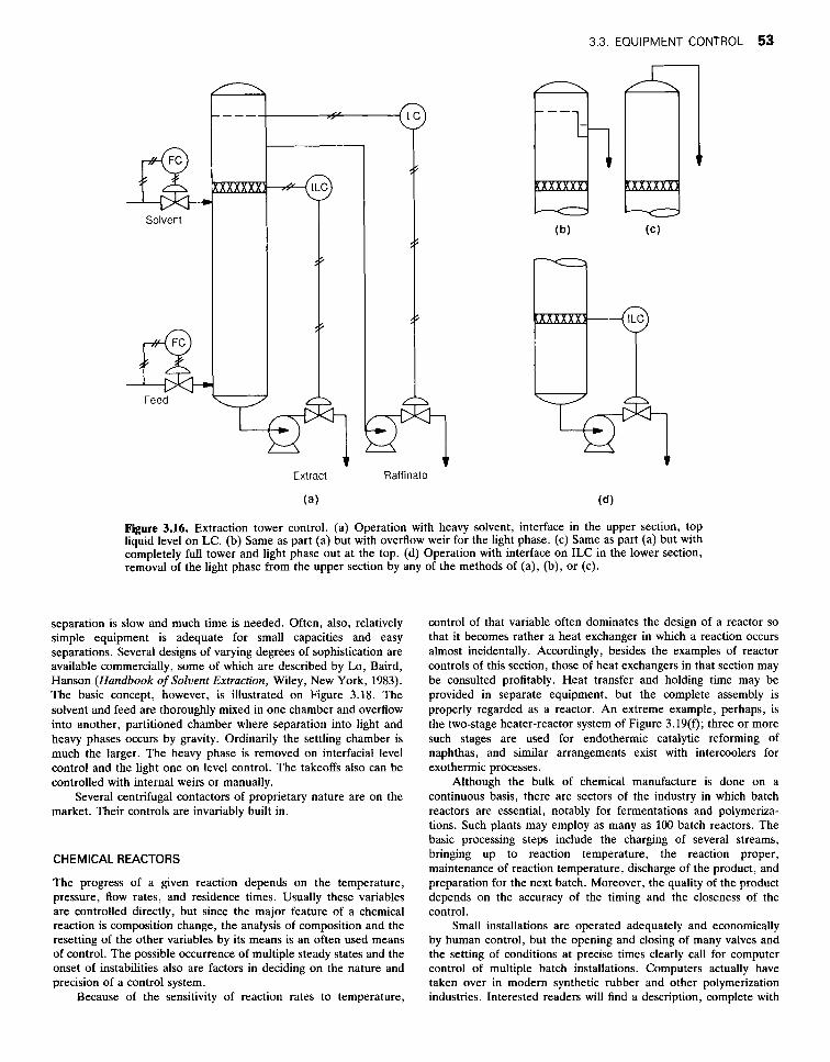
Figure 3.16. Extraction tower control. (a) Operation with heavy solvent, interface in the upper section, top liquid level on LC. (b) Same as part (a) but with overflow weir for the light phase. (c) Same as part (a) but with completely full tower and light phase out at the top. (d) Operation with interface on ILC in the lower section, removal of the light phase from the upper section by any of the methods of (a), (b), or (c).
separation is slow and much time is needed. Often, also, relatively simple equipment is adequate for small capacities and easy separations. Several designs of varying degrees of sophistication are available commercially, some of which are described by Lo, Baird, Hanson (Handbook of Solvent Extraction, Wiley, New York, 1983). The basic concept, however, is illustrated on Figure 3.18. The solvent and feed are thoroughly mixed in one chamber and overflow into another, partitioned chamber where separation into light and heavy phases occurs by gravity. Ordinarily the settling chamber is much the larger. The heavy phase is removed on interfacial level control and the light one on level control. The takeoffs also can be controlled with internal weirs or manually.
Several centrifugal contactors of proprietary nature are on the market. Their controls are invariably built in.
CHEMICAL REACTORS
The progress of a given reaction depends on the temperature, pressure, flow rates, and residence times. Usually these variables are controlled directly, but since the major feature of a chemical reaction is composition change, the analysis of composition and the resetting of the other variables by its means is an often used means of control. The possible occurrence of multiple steady states and the onset of instabilities also are factors in deciding on the nature and precision of a control system.
Because of the sensitivity of reaction rates to temperature,
control of that variable often dominates the design of a reactor so that it becomes rather a heat exchanger in which a reaction occurs almost incidentally. Accordingly, besides the examples of reactor controls of this section, those of heat exchangers in that section may be consulted profitably. Heat transfer and holding time may be provided in separate equipment, but the complete assembly is properly regarded as a reactor. An extreme example, perhaps, is the two-stage heater-reactor system of Figure 3.19(f); three or more such stages are used for endothermic catalytic reforming of naphthas, and similar arrangements exist with intercoolers for exothermic processes.
Although the bulk of chemical manufacture is done on a continuous basis, there are sectors of the industry in which batch reactors are essential, notably for fermentations and polymeriza- tions. Such plants may employ as many as 100 batch reactors. The basic processing steps include the charging of several streams, bringing up to reaction temperature, the reaction proper, maintenance of reaction temperature, discharge of the product, and preparation for the next batch. Moreover, the quality of the product depends on the accuracy of the timing and the closeness of the control.
Small installations are operated adequately and economically by human control, but the opening and closing of many valves and the setting of conditions at precise times clearly call for computer control of multiple batch installations. Computers actually have taken over in modern synthetic rubber and other polymerization industries. Interested readers will find a description, complete with

54 PROCESS CONTROL
I Raffinate
k
Flow Ratio Control
J - I
Reset
Solvent m
h Reset I.?
Solvent or Feed
Figure 3.17. Some other controls on extraction towers. (a) Solvent flow rate maintained in constant ratio with the feed rate. (b) Solvent flow rate reset by controlled composition of raffinate. (c) Temperature of solvent or feed reset by the temperature at a control point in the tower.
logic diagrams for normal and emergency operations, of the tasks involved in generating a computer system for a group of batch reactors in the book of Liptak (1973, pp. 536-565). Control of discontinuous processes in general is treated in the book of Skrokov
In the present discussion, emphasis will be placed on the control of continuous reactors, concentrating on the several examples of Figure 3.19 in the order of the letter designations of individual figures used there.
(1980, pp. 128-163).
(a) Stirred tanks are used either as batch or continuous flow reactors. Heat transfer may be provided with an external heat exchanger, as shown on this figure, or through internal surface or a jacket. Alternate modes of control may be used with the controls shown: (i) When the HTM is on temperature control, the pumparound will be on flow control; (ii) when the pumparound is on temperature control, the HTM will be on flow control; (iii) for continuous overflow of product, the control point for temperature may be on that line or in the vessel; (iv) for batch operation, the control point for temperature clearly must be in the vessel. Although level control is shown to be maintained with an internal weir, the product can be taken off with the pump on level control.
(b) This shows either direct or cascade control of the temperature of a reactor with internal heat transfer surface and an internal weir. The sluggishly responding temperature of the vessel is used to reset the temperature controller of the HTM. For direct control, the TC-2 is omitted and the control point can be on the HTM outlet or the product line or in the vessel.
(e) Quite a uniform temperature can be maintained in a reactor if the contents are boiling. The sketch shows temperature maintenance by refluxing evolved vapors. A drum is shown from which uncondensed gases are drawn off on pressure control, but the construction of the condenser may permit these gases to be drawn off directly, thus eliminating need for the drum. The HTM of the condenser is on TC which resets the PC if necessary in order to maintain the correct boiling temperature in the reactor. Other modes of pressure control are shown withthe fractionator sketches of Figure 3.15 and on Figure 3.5 dealing with vacuum control.
(a) Flow reactors without mechanical agitation are of many configurations, tanks or tubes, empty or containing fixed beds of particles or moving particles. When the thermal effects of reaction are substantial, multiple small tubes in parallel are used to provide adequate heat transfer surface. The sketch shows a single tube provided with a jacket for heat transfer. Feed to the reactor is on flow control, the effluent on pressure control, and the flow of the HTM on temperature control of the effluent with the possibility of reset by the composition of the effluent.
(e) Heat transfer to high temperature reactions, above 300°C or so, may be accomplished by direct contact with combustion gases. The reaction tubes are in the combustion zone but safely away from contact with the flame. The control mode is essentially similar to that for case (d), except that fuel-air mixture takes the place of the HTM. The supply of fuel is on either temperature or composition control off the effluent stream, and the air is maintained in constant ratio with the fuel with the flow ratio controller FRC.
(4 High temperature endothermic processes may need several reaction vessels with intermediate heat input. For example, the inlet temperature to each stage of a catalytic reformer is about 975°F and the temperature drop ranges from about 100°F in the first stage to about 15°F in the last one. In the two-stage assembly of this figure, the input is on FC, the outlet of the last reactor on PC, and the fuel supply to each furnace is on TC of its effluent, with the air supply on flow ratio control, as shown for example (e).
(9) Very effective heat transfer is accomplished by mixing of streams at different temperatures. The cumene process shown here employs injection of cold reacting mixture and cold inert propane and water to prevent temperature escalation; by this scheme, the inlet and outlet temperature are made essentially the same, about 500°F. Although not shown here, the main feed is, as usual for reactors, on FC and the outlet on PC. The

3.3. EQUIPMENT CONTROL 55
ix Solvent
Mixing Chamber
Light Phase
Figure 3.18. Functioning and controls of a mixer-settler assembly for liquid-liquid extraction.
LIQUID PUMPS
Heavy Phase
Separating Chamber
sidestreams are regulated with hand-set valves by experienced operators in this particular plant, but they could be put on automatic control if necessary. Other processes that employ injection of cold process gas at intermediate points are some cases of ammonia synthesis and sulfur dioxide oxidation.
(h) In catalytic cracking of petroleum fractions, an influential side reaction is the formation of carbon which deposits on the catalyst and deactivates it. Unacceptable deactivation occurs in about lOmin, so that in practice continuous reactivation of a portion of the catalyst in process must be performed. As shown on this sketch, spent catalyst is transferred from the reactor to the regenerator on level control, and returns after regeneration under TC off the reactor temperature. Level in the regenerator is maintained with an overflow standpipe. Smooth transfer of catalyst between vessels is assisted by the differential pressure control DPC, but in some plants transfer is improved by injection of steam at high velocity into the lines as shown on this sketch for the input of charge to the reactor. Feed to the system as a whole is on flow control. Process effluent from the reactor is on pressure control, and of the regenerator gases on the DPC. Fuel to regeneration air preheater is on TC off the preheat air and the combustion air is on flow ratio control as in part (e).
Process pumps are three types: centrifugal, rotary positive displacement, and reciprocating. The outputs of all of them are controllable by regulation of the speed of the driver.
Controllability of centrifugal pumps depends on their pressure- flow characteristics, of which Figure 3.20 has two examples. With the upper curve, two flow rates are possible above a head of about 65ft so that the flow is not reliably controllable above this pressure. The pump with the lower curve is stable at all pressures within its range. Throttling of the discharge is the usual control method for smaller centrifugals, variable speed drives for larger ones. Suction throttling may induce flashing and vapor binding of the pump. Figures 3.21(a) and (b) are examples.
Rotary pumps deliver a nearly constant flow at a given speed, regardless of the pressure. Bypass control is the usual method, with speed control in larger sizes. Reciprocating pumps also may be controlled on bypass if a pulsation damper is provided in the circuit to smooth out pressure fluctuations; Figure 3.21(c) shows this mode.
Reciprocating positive displacement pumps may have adjust- ment of the length or frequency of the stroke as another control feature. These may be solenoid or pneumatic devices that can be operated off a flow controller, as shown on Figure 3.21(d).
SOLIDS FEEDERS
Several of the more common methods of controlling the rate of supply of granular, free-flowing solids are represented in Figure 3.7.
COMPRESSORS
Three main classes of gas compressors are centrifugal and axial, rotary continuous positive displacement, and reciprocating positive

56 PROCESS CONTROL
Recycle - Feed 1
TM
(C) 4 Product
Feed Product
Figure 3.19. Chemical reactor control examples. (a) Temperature control of a stirred tank reactor with pumparound through an external heat exchanger, operable either in batch or continuously: Some alternate control modes are discussed in the text. Cascade control as in (b) can be implemented with external heat transfer surface. (b) Either cascade or direct control of temperature: For direct control, controller TC-2 is omitted, and the control point can be taken on the effluent line or in the vessel or on the HTM effluent line. A similar scheme is feasible with an external heat exchanger. (c) Reactor temperature control by regulation of the boiling pressure: The HTh4 is on TC off the reactor and resets the PC on the vent gases when necessary to maintain the correct boiling temperature. Although shown for batch operation, the method is entirely feasible for continuous flow. (d) Basic controls on a flow reactor: Feed on flow control, effluent on pressure control, and heat transfer medium flow rate on process effluent temperature or reset by its composition. (e) A fired heater as a tubular flow reactor: Feed is on FC, the product is on PC, the fuel is on TC or AC off the product, and the air is on flow ratio control. (f) A two-stage fired heater-reactor assembly: Details of the fuel-air supply control are in (e). (g) Control of the temperature of the exothermic synthesis of cumene by splitting the feed and by injection of cold propane and water into several zones. The water also serves to maintain activity of the phosphoric acid catalyst. (h) The main controls of a fluidized bed reactor-regenerator: Flow of spent catalyst is on level control, and that of regenerated catalyst is on TC off the reactor; these flows are assisted by maintenance of a differential pressure between the vessels. Details of the fuel-air control for the preheater are in (e).

3.3. EQUIPMENT CONTROL 57
Reset
Air
Product Fuel 4 " Fuel T u " Air 1 Air (D
(9)
Figure 3.l%-(continued)
and Benzene
Cumene

58 PROCESS CONTROL
Separator Reactor D
Liquid
\ / ,
Regenerator Water
W l c h h u -
Steam
Controlled TernDerature
5 - AirPreheater
Regenerator Air
Figure 3.19-(conrinued)
d ril a, I
0 60 120 Flow Rate, gpm
Figure 3.20. Characteristics curves of two centrifugal pumps.
displacement. The usual or feasible modes of control of pressure and flow may be tabulated:
Control Mode Centrifugal Rotary Reciprocating andAxial PD PD
Suction throttling X
Discharge throttling x Bypass X X X
Speed X X X
Guide vanes X
Suction valves X
Cylinder clearance X
(b)
Figure 3.21. Control of centrifugal, rotary, and reciprocating pumps. (a) Throttling of the discharge of a centrifugal pump. (b) Control of the flow rate of any kind of pump by regulation of the speed of the driver. Although a turbine is shown, engine drive or speed control with gears, magnetic clutch, or hydraulic coupling may be feasible. (c) On the left, bypass control of rotary positive displacement pump; on the right, the reciprocating pump circuit has a pulsation dampener to smooth out pressure fluctuations. (d) Adjustment of the length or frequency of the stroke of a constant speed reciprocating pump with a servomechanism which is a feed- back method whose action is control of mechanical position.

3.3. EQUIPMENT CONTROL 59
pressor must be maintained above the magnitude at the peak in pressure. Figure 3.23(c) shows an automatic bypass for surge protection which opens when the principal flow falls to the critical minimum; recycle brings the total flow above the critical.
Smaller rotary positive displacement compressors are con- trolled with external bypass. Such equipment usually has a built-in relief valve that opens at a pressure short of damaging the equipment, but the external bypass still is necessary for smooth control. Large units may be equipped with turbine or gas engine drives which are speed adjustable. Variable speed gear boxes or belt drives are not satisfactory. Variable speed dc motors also are not useful as compressor drives. Magnetic clutches and hydraulic couplings are used.
Reciprocating compressors may be controlled in the same way as rotary units. The normal turndown with gasoline or diesel engines is 50% of maximum in order that torque remains within
(C)
(d)
Figure 3.2l-(con?inued)
Throttling of the suction of centrifugal and axial compressors wastes less power than throttling the discharge. Even less power is wasted by adjustment of built-in inlet guide vanes with a servomechanism which is a feedback control system in which the controlled variable is mechanical position. Speed control is a particularly effective control mode, applicable to large units that can utilize turbine or internal combustion drives; control is by throttling of the supply of motive fluids, steam or fuel.
Characteristic curves-pressure against flowrate-f centrifugal and axial compressors usually have a peak. Figure 3.22 is an example. In order to avoid surging, the flow through the com-
m v) Q
._
0- 0 5 10
Flow Rate, M Ib/hr Figure 3.22. Characteristic curves of a centrifugal compressor at different speeds, showing surge limits.
El
n
(C)
Figure 3.23. Control of centrifugal compressors with turbine or motor drives. (a) Pressure control with turbine or motor drives. (b) Flow control with turbine or motor drives. SC is a servomechanism that adjusts the guide vanes in the suction of the compressor. (c) Surge and pressure control with either turbine or motor drive. The bypass valve opens only when the flow reaches the minimum calculated for surge protection.

60 PROCESS CONTROL
Figure 3.24. Control of positive displacement compressors, rotary and reciprocating. (a) Flow control with variable speed drives. (b) Pressure control with bypass to the suction of the compressor. (c) Reciprocating compressor. SC is a servomechanism that opens some of suction valves during discharge, thus permitting stepwise internal bypass. The clearance unloader is controllable similarly. These built-in devices may be supplemented with external bypass to smooth out pressure fluctuations.
acceptable limits. Two other aids are available to control of recip- rocating units.
1. Valve unloading, a process whereby some of the suction valves remain open during discharge. Solenoid or pneumatic unloaders can be operated from the output of a control instrument. The stepwise controlled flow rate may need to be supplemented with controlled external bypass to smooth out pressure fluctuations.
2. Clearance unloaders are small pockets into which the gas is forced on the compression stroke and expands into the cylinder on the return stroke, thus preventing compression of additional gas.
Figure 3.24 shows control schemes for rotary and reciprocating compressors. Vacuum pumps are compressors operating between a low suction pressure and a fixed discharge pressure, usually
atmospheric. Mechanical pumps are used for small capacities, steam jet ejectors for larger ones. Ejectors also are used as ther- mocompressors to boost the pressure of low pressure steam to an intermediate value. Control of suction pressure with either mech- anical or jet pumps is by either air bleed [Fig. 3S(a)] or suction line throttling [Fig. 3.5(c)]; air bleed is the more economical process. Up to five jets in series are used to produce high vacua. The steam from each stage is condensed by direct contact with water in baro- metric condensers or in surface condensers; condensation of steam from the final stage is not essential to performance but only to avoid atmospheric pollution. In a single stage ejector, motive steam flow cannot be reduced below critical flow in the diffuser, and water to the barometric condenser must not be throttled below 30-50% of the maximum if proper contacting is to be maintained. Control by throttling of steam and water supply, as on Figure 3.5(b), is subject to these limitations.
REFERENCES
1. Chemical Engineering Magazine, Practical Process Instrumentation and
2. D.M. Considine, Process Instruments and Controh Handbook, McGraw-
3. B. Liptak, Instrumentation in the Process Industries, Chilton, New York,
4. F.G. Shinskey, Process Control Systems, McGraw-Hill, New York, 1919. 5. F.G. Shinskey, Distillation Control, McGraw-Hill, New York, 1984. 6. M.R. Skrokov (Ed.), Mini- and Microcomputer Control in Industrial
1973.
Control, McGraw-Hill, New York, 1980.
Hill, New York, 1985. Processes, Van Nostrand Reinhold, New York, 1980.