process control system pcs 7 communication blocks · process control system pcs 7, communication...
TRANSCRIPT

Contents
Communication blocks 1Index
SIMATIC
Process Control System PCS 7Communication Blocks
Reference Manual
Edition 08/2001A5E00127657-01
17.08.2001

Copyright © Siemens AG 2001 All rights reserved
The reproduction, transmission or use of this document or itscontents is not permitted without express written authority.Offenders will be liable for damages. All rights, including rightscreated by patent grant or registration of a utility model or design,are reserved.
Siemens AGBereich Automatisierungs- und AntriebstechnikGeschaeftsgebiet Industrie-AutomatisierungssystemePostfach 4848, D- 90327 Nuernberg
Disclaimer of Liability
We have checked the contents of this manual for agreement withthe hardware and software described. Since deviations cannot beprecluded entirely, we cannot guarantee full agreement. However,the data in this manual are reviewed regularly and any necessarycorrections included in subsequent editions. Suggestions forimprovement are welcomed.
©Siemens AG 2001Technical data subject to change.
Siemens Aktiengesellschaft A5E00127657
Safety Guidelines
This manual contains notices intended to ensure personal safety, as well as to protect the products and
connected equipment against damage. These notices are highlighted by the symbols shown below and
graded according to severity by the following texts:
! Dangerindicates that death, severe personal injury or substantial property damage will result if properprecautions are not taken.
! Warningindicates that death, severe personal injury or substantial property damage can result if properprecautions are not taken.
! Cautionindicates that minor personal injury can result if proper precautions are not taken.
Cautionindicates that property damage can result if proper precautions are not taken.
Noticedraws your attention to particularly important information on the product, handling the product, or to aparticular part of the documentation.
Qualified Personnel
Only qualified personnel should be allowed to install and work on this equipment. Qualified persons are
defined as persons who are authorized to commission, to ground and to tag circuits, equipment, and
systems in accordance with established safety practices and standards.
Correct Usage
Note the following:
! WarningThis device and its components may only be used for the applications described in the catalog or the
technical description, and only in connection with devices or components from other manufacturers
which have been approved or recommended by Siemens.
This product can only function correctly and safely if it is transported, stored, set up, and installedcorrectly, and operated and maintained as recommended.
Trademarks
SIMATIC®, SIMATIC HMI® and SIMATIC NET® are registered trademarks of SIEMENS AG.
Third parties using for their own purposes any other names in this document which refer to trademarks might
infringe upon the rights of the trademark owners.
17.08.2001
Process Control System PCS 7, Communication BlocksA5E00127657-01 iii
Contents
1 Communication blocks .....................................................................................................1-1
1.1 FR_BSEND .......................................................................................................1-11.1.1 FR_BSEND: Call frame for BSEND..................................................................1-11.1.2 Connections of FR_BSEND..............................................................................1-51.2 FR_BRCV..........................................................................................................1-61.2.1 FR_BRCV: Call frame for BRCV.......................................................................1-61.2.2 Connections of FR_BRCV ................................................................................1-91.3 FR_USEND.....................................................................................................1-101.3.1 FR_USEND: Call frame for USEND ...............................................................1-101.3.2 Connections of FR_USEND............................................................................1-141.4 FR_URCV .......................................................................................................1-151.4.1 FR_URCV: Call frame for URCV ....................................................................1-151.4.2 Connections of FR_URCV ..............................................................................1-171.5 FR_AGSEN.....................................................................................................1-181.5.1 FR_AGSEN: Call frame for AG_SEND...........................................................1-181.5.2 Connections of FR_AGSEN............................................................................1-211.6 FR_AGRCV.....................................................................................................1-221.6.1 FR_AGRCV: Call frame for AG_RECV...........................................................1-221.6.2 Connections of FR_AGRCV............................................................................1-241.7 SEND_BO .......................................................................................................1-251.7.1 SEND_BO: Send 128 BOOL values with BSEND ..........................................1-251.7.2 Connections of SEND_BO..............................................................................1-271.8 REC_BO..........................................................................................................1-281.8.1 REC_BO: Receive 128 BOOL values with BRCV ..........................................1-281.8.2 Connections of REC_BO ................................................................................1-301.9 SEND_R..........................................................................................................1-311.9.1 SEND_R: Send 32 BOOL and 32 REAL values driven by changes
with BSEND.....................................................................................................1-311.9.2 Connections of SEND_R.................................................................................1-341.10 REC_R ............................................................................................................1-351.10.1 REC_R: Receive 32 BOOL and 32 REAL values with BRCV ........................1-351.10.2 Connections of REC_R...................................................................................1-37
17.08.200117.08.2001

Contents
Process Control System PCS 7, Communication Blocksiv A5E00127657-01
17.08.200117.08.2001

Process Control System PCS 7, Communication BlocksA5E00127657-01 1-1
1 Communication blocks
1.1 FR_BSEND
1.1.1 FR_BSEND: Call frame for BSEND
Object name (Type + Number)
FB 201
Area of Application
The block forms a simple interface to the block SFB12 BSEND for the user.
It sends data via an MPI, PROFIBUS or Industrial Ethernet connection to a furtherS7 CPU that has to call the function block type "BRCV" (FC_BRCV or SFB13BRCV) in order to receive the data. Only data blocks are allowed as data sourcesor data targets. In STEP7, a homogeneous transport connection is to be installedon both sides and is to be transferred into the automation device.
The FR_BSEND should be used instead of the FR_USEND if the extent of dataexceeds 440 bytes, or if a secured transmission is required for an extent of databelow 440 bytes (acknowledgment is not carried out until the data are entered inthe receiver-DB - the acknowledgment is signaled by a signal change to 0 at theoutput CIW).
Since data transmission is carried out in segmented form, the data are onlyavailable consistently in the receiver-DB after the job has been completed(meaning after the acknowledged has arrived).
If the parameter FAST is interconnected with 1, the FB allows the sending of onemessage per function block call possible, because it then internally calls the SFB12BSEND twice (the SFB12 requires an edge change from 0 to 1 at the control inputREQ to be activated). However, it is only advisable to use such frequent send jobassignment placing if there is enough time to transfer the message between twoFB calls.
17.08.200117.08.2001

Communication blocks
Process Control System PCS 7, Communication Blocks1-2 A5E00127657-01
Calling OBs
The watchdog interrupt OB into which the block is installed (for example OB35).
Operating principle
Send-DB
Buffer
Receive-DB
Transmitter Receiver
MPI or Ethernet/point-to-point
Function blockFR_BSEND
Buffer
Operating system Operating system
Order with ID,Send-DB-No., Data length max 32kb
read
Function blockFR_BRCV
Order with ID,Receive-DB-NO.,Data length max. 32kb
max. 440 byte max 440 byte
Acknowledgement
Sequence of a telegram
It is possible to transport a greater data quantity (up to 32 Kbytes) between thecommunication partners with the internally used SFB12 BSEND than with all othercommunication SFBs for configured connections. This is because the data range tobe sent is segmented. Each segment is sent separately from the CPU operatingsystem to the partner when it is entered automatically by the operating system intothe receive-DB. Before the next segment is sent the system waits for the operating-system-internal acknowledgment of the segment just sent.
The send process is activated by the block being called with the value 1 at thecontrol input COM. The block must be called at least once (independently of thecycle) to carry out complete transfer of the parameterized data range. The blocktransfers the job to the CPU operating system which carries out the job completely.Further calls of the block with the same ID and the same R_ID during thetransmission are allowed. However, they have no function (i.e. the block can becalled once per cycle). Instead, the value 11 is displayed at the output STAT.Reading of the data from the user memory (corresponds to the "Send-DB" in thefigure above) is carried out asynchronously to the processing of the user program.The smallest continuous data quantity that is read consistently by the operatingsystem from the user memory is 32 bytes for the CPUs 4xx. If consistency is alsorequired at the 32-byte limit, the data in the send-DB may not be modified after theFR_BSEND has been called as long as the job is running (CIW=1). If the job iscompleted without errors and a pulse was supplied to the input COM (0 -> 1 -> 0),CIW is set to 0. (In case of an error a new job is triggered automatically with thecurrent data until the transfer has been successful). If the input COM is supplied
17.08.200117.08.2001
Communication blocks
Process Control System PCS 7, Communication BlocksA5E00127657-01 1-3
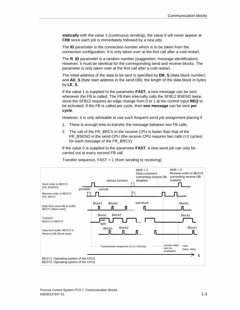
statically with the value 1 (continuous sending), the value 0 will never appear atCIW since each job is immediately followed by a new job).
The ID parameter is the connection number which is to be taken from theconnection configuration. It is only taken over at the first call after a cold restart.
The R_ID parameter is a random number (suggestion: message identification).However, it must be identical for the corresponding send and receive blocks. Theparameter is only taken over at the first call after a cold restart.
The initial address of the data to be sent is specified by DB_S (data block number)and AD_S (byte start address in the send DB), the length of the data block in bytesby LE_S.
If the value 1 is supplied to the parameter FAST, a new message can be sentwhenever the FB is called. The FB then internally calls the SFB12 BSEND twice,since the SFB12 requires an edge change from 0 to 1 at the control input REQ tobe activated. If the FB is called per cycle, then one message can be sent percycle.
However, it is only advisable to use such frequent send job assignment placing if
1. There is enough time to transfer the message between two FB calls.
2. The call of the FR_BRCV in the receive CPU is faster than that of theFR_BSEND in the send CPU (the receive CPU requires two calls (=2 cycles)for each message of the FR_BRCV).
If the value 0 is supplied to the parameter FAST, a new send job can only becarried out at every second FB call.
Transfer sequence, FAST = 1 (from sending to receiving)
t
Send order to BESY1(FR_BSEND)
Receive order to BESY2(FR_BRCV
Data from send-DB to bufferBESY1 (block-wise)
TransmitBESY1 to BESY2
Data from buffer BESY2 inReceive-DB (block-wise)
Transmission sequence (1 to n blocks) next
´possible normal
without function
Block1 Block2 last block Block1
Block1
Block1Block1
Block1
Block2
Block2
440byte
receive datacan beevaluated
BESY1: Operating system of the CPU1BESY2: Operating system of the CPU2
NDR = 1Data consistentoverwriting receive-DBdisabled
NDR = 0Receive-order to BESY2overwriting receive-DBenabled
trans. sequ.
17.08.200117.08.2001
Communication blocks
Process Control System PCS 7, Communication Blocks1-4 A5E00127657-01
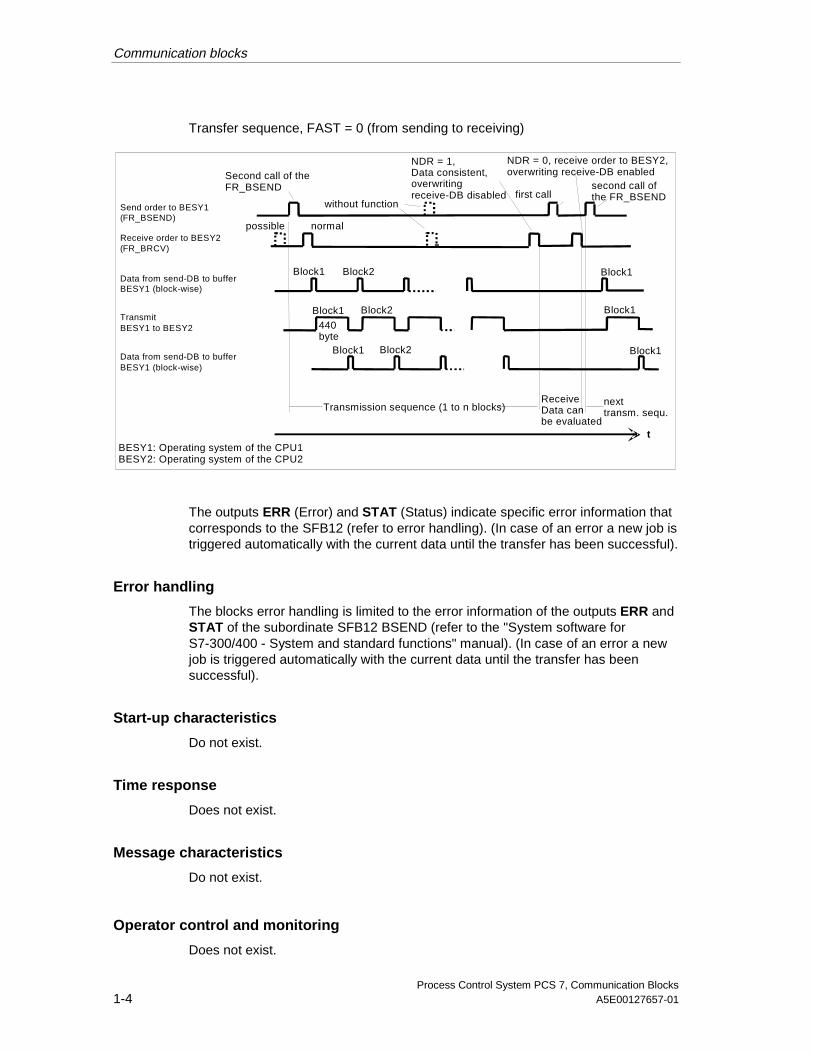
Transfer sequence, FAST = 0 (from sending to receiving)
Send order to BESY1(FR_BSEND)
Receive order to BESY2(FR_BRCV)
Data from send-DB to bufferBESY1 (block-wise)
TransmitBESY1 to BESY2
Data from send-DB to bufferBESY1 (block-wise)
Second call of theFR_BSEND
without function
possible normal
Block1
Block2
Block2
Block2
440byte
Block1
Block1
Block1
Block1
Block1
Transmission sequence (1 to n blocks) nexttransm. sequ.
ReceiveData canbe evaluated
t
first callsecond call ofthe FR_BSEND
NDR = 1,Data consistent,overwritingreceive-DB disabled
NDR = 0, receive order to BESY2,overwriting receive-DB enabled
BESY1: Operating system of the CPU1BESY2: Operating system of the CPU2
The outputs ERR (Error) and STAT (Status) indicate specific error information thatcorresponds to the SFB12 (refer to error handling). (In case of an error a new job istriggered automatically with the current data until the transfer has been successful).
Error handling
The blocks error handling is limited to the error information of the outputs ERR andSTAT of the subordinate SFB12 BSEND (refer to the "System software forS7-300/400 - System and standard functions" manual). (In case of an error a newjob is triggered automatically with the current data until the transfer has beensuccessful).
Start-up characteristics
Do not exist.
Time response
Does not exist.
Message characteristics
Do not exist.
Operator control and monitoring
Does not exist.
17.08.200117.08.2001

Communication blocks
Process Control System PCS 7, Communication BlocksA5E00127657-01 1-5
1.1.2 Connections of FR_BSEND
The state of delivery of the block display in the CFC is marked in the "Connection"column: Connection name bold = Connection displayed, normal = Not displayed.
Connection(parameter)
Meaning Data type Initial I/O
AD_S Start address in the send DB in bytes INT 0 I
CIW Job being executed BOOL 0 O
COM Send commandStatic 1: Send continuouslyPulse 1: Send once
BOOL 0 I
DB_S Send data block number INT 0 I
ERR Error (for error type see STAT) BOOL 0 O
FAST Transfer type1 = One message can be transferred per FBcall0 = One message can be transferred with twoFB calls
BOOL 0 I
ID Connection ID WORD 0 I
LE_S Send data length in bytes INT 0 I
R_ID Message ID DWORD 0 I
STAT Error ID WORD 0 O
17.08.200117.08.2001

Communication blocks
Process Control System PCS 7, Communication Blocks1-6 A5E00127657-01
1.2 FR_BRCV
1.2.1 FR_BRCV: Call frame for BRCV
Object name (Type + Number)
FB 202
Area of Application
The block forms a simple interface to the block SFB13 BRCV for the user.
It receives data via an MPI, PROFIBUS or Ethernet connection from a further S7CPU that has to call the function block type "BSEND" (FC_BSEND or SFB12BSEND) in order to send the data. Only data blocks are allowed as data targets. InSTEP7, a homogeneous transport connection is to be installed on both sides andis to be transferred into the automation device.
The FR_BRCV should be used instead of the FR_URCV if the extent of dataexceeds 440 bytes, or if a secured transmission is required for an extent of databelow 440 bytes (acknowledgment is not carried out until the data are entered inthe receiver-DB - the acknowledgment is signaled by a signal change to 1 at theoutput NDR).
Since data transmission is carried out in segmented form, the data are onlyavailable after the job has been completed (meaning after the signal change of theoutput NDR from 0 to 1).
Calling OBs
The watchdog interrupt OB into which the block is installed (for example OB35).
17.08.200117.08.2001

Communication blocks
Process Control System PCS 7, Communication BlocksA5E00127657-01 1-7
Operating principle
Send-DB
Buffer
Receive-DB
Transmitter Receiver
MPI or Ethernet/point-to-point
Function blockFR_BSEND
Buffer
Operating system Operating system
Order with ID,Send-DB-No., Data length max 32kb
read
Function blockFR_BRCV
Order with ID,Receive-DB-NO.,Data length max. 32kb
max. 440 byte max 440 byte
Acknowledgement
Sequenceof a telegram
It is possible to transport a greater data quantity (up to 32 Kbytes) between thecommunication partners with the internally used SFB13 BRCV than with all othercommunication SFBs for configured connections. This is because the data range tobe sent is segmented. Each segment is received separately by the CPU operatingsystem and is entered in the receive-DB. Before the next segment can be receivedan operating-system-internal acknowledgment of the segment just received has tobe sent.
Entering of the data into the user memory (corresponds to the "Receive DB" in thefigure above) is carried out asynchronously to the processing of the user program.The smallest continuous data quantity that is written consistently by the operatingsystem into the user memory is 32 bytes for the CPUs 4xx. If consistency is alsorequired at the 32-byte limit, the data in the receive DB may not be modified afterthe FR_BRCV has been called as long as the job is running (NDR = 1). If the jobhas been completed without errors, the output NDR is set to 1 for one cycle. In thesubsequent cycle the FB automatically provides the receive enable to the CPUoperating system (NDR is 0 again from and including this call).
The receive enable can already be effective before the first receive job arrives. Inthis case it is stored by the operating system.
The ID parameter is the connection number which is to be taken from theconnection configuration. It is only taken over at the first call after a cold restart.
The R_ID parameter is a random number (suggestion: message identification).However, it must be identical for the corresponding send and receive blocks. Theparameter is only taken over at the first call after a cold restart.
17.08.200117.08.2001
Communication blocks
Process Control System PCS 7, Communication Blocks1-8 A5E00127657-01
A call of the FR_BRCV must be carried out for each ID/R_ID pair in each programcycle (cyclically or also via time interrupts) Two calls of the FR_BRCV are requiredfor each message.
The initial address of the target area of the received data is specified by DB_R(data block number) and AD_R (initial address in the receive DB in bytes). Theparameter LE_MAX specifies the maximum number of receivable data in bytes.
The parameter LE_R specifies the number of data already received in bytes atevery cycle.
The outputs ERR (Error) and STAT (Status) indicate specific error information thatcorresponds to the SFB13 (refer to error handling).
Error handling
The blocks error handling is limited to the error information of the outputs ERR andSTAT of the subordinate SFB13 BRCV (refer to the "System software for S7-300/400 - System and standard functions" manual).
Start-up characteristics
Do not exist.
Time response
Does not exist.
Message characteristics
Do not exist.
Operator control and monitoring
Does not exist.
17.08.200117.08.2001

Communication blocks
Process Control System PCS 7, Communication BlocksA5E00127657-01 1-9
1.2.2 Connections of FR_BRCV
The state of delivery of the block display in the CFC is marked in the "Connection"column: Connection name bold = Connection displayed, normal = Not displayed.
Connection(parameter)
Meaning Data type Initial I/O
AD_R Start address in the receive DB in bytes INT 0 I
DB_R Receive data block number INT 0 I
ERR Error (for error type see STAT) BOOL 0 O
ID Connection ID WORD 0 I
LE_MAX Maximum receive data length in bytes INT 0 I
LE_R Currently received data length in bytes INT 0 O
NDR 1 = New data in the receive DB Data areconsistent
BOOL 0 O
R_ID Message ID DWORD 0 I
STAT Error ID WORD 0 O
17.08.200117.08.2001

Communication blocks
Process Control System PCS 7, Communication Blocks1-10 A5E00127657-01
1.3 FR_USEND
1.3.1 FR_USEND: Call frame for USEND
Object name (Type + Number)
FB 203
Area of Application
The block forms a simple interface to the block SFB8 USEND for the user.
It sends data via an MPI, PROFIBUS or Industrial Ethernet connection to a furtherS7 CPU (with MPI also M7 or M7-S7) that has to call the function block type"URCV" (FC_URCV or SFB8 URCV) in order to receive the data. Only data blocksare allowed as data sources or data targets. In STEP7, a homogeneous transportconnection is to be installed on both sides and is to be transferred into theautomation device.
The FR_USEND can be used instead of the FR_BSEND if the data range issmaller than 440 bytes, data consistency is required consistently across thecomplete send data area and no secured transmission is demanded.
On "Data consistency": The data are constantly consistent in the receive DB (incontrast to the FR_BSEND). This is ensured by the fact that the data are alreadycopied completely and directly into the buffer - resp. from the buffer - of theoperating system when the function blocks FR_USEND and FR_UREC are calledby these function blocks. Inconsistency can only occur if the copy procedure isinterrupted by an interrupt program (corresponds to interruption of the subordinateSFB8 USEND or SFB9 URCV) and if the send/receive data are modified in theinterrupt program.
On "No secured transfer": In the case of FR_URCV/URCV the acknowledgment isgenerated on the operating-system-level without constant coordination. This meansthat the acknowledgment also arrives at the FR_USEND when the data could notbe entered into the receive DB, for example when the receive CPU is in STOP. Theacknowledgment can be recognized by the fact that the signal changes to 0 at theoutput CIW.
If the parameter FAST is interconnected with 1, the FB allows the sending of onemessage per function block call possible, because it then internally calls the SFB8USEND twice (the SFB8 requires an edge change from 0 to 1 at the control inputREQ to be activated). However, it is only advisable to use such frequent send jobassignment placing if there is enough time to transfer the message between twoFB calls.
17.08.200117.08.2001

Communication blocks
Process Control System PCS 7, Communication BlocksA5E00127657-01 1-11
Calling OBs
The watchdog interrupt OB into which the block is installed (for example OB35).
Operating principle
Send-DB
Buffer
Receive-DB
Transmitter Receiver
MPI, Ind.Ethernet,PROFIBUS
Function blockFR_USEND
Buffer
Operating system Operating system
Copydataconsistently
Function blockFR_URCV
max.440byte max. 440 byte
Acknowledgement
Sequence of a telegram
max. 440 byte
Order withID, R_ID,data length
Copydataconsistently
Order withID, R_ID,data length
A data quantity of 440 bytes can be transferred consistently between thecommunication partners by means of the SFB8 USEND used internally. The sendprocedure is carried out with regard to the acknowledgment without coordinationwith the receive function block. This means that the acknowledgment is generatedby the operating system of the receiver without waiting for the call of the receiveblock.
The send process is activated by the block being called with the value 1 at thecontrol input COM. The block must be called at least once (independently of thecycle) to carry out complete transfer of the parameterized data range. The blockcopies the complete data from the send DB consistently into the buffer of the CPUoperating system and transfers the send job to the operating system. Further callsof the block with the same ID and the same R_ID during the transmission areallowed. However, they have no function (i.e. the block can be called once percycle). Instead, the value 11 is displayed at the output STAT.
The value 1 is displayed at the state parameter CIW as long as the sendingprocess is running. If the job is completed without errors and a pulse was suppliedto the input COM (0-> 1 -> 0), CIW is set to 0. (In case of an error a new job istriggered automatically with the current data until the transfer has been successful).If the input COM is supplied statically with the value 1 (continuous sending), thevalue 0 will never appear at CIW since each job is immediately followed by a newjob).
17.08.200117.08.2001

Communication blocks
Process Control System PCS 7, Communication Blocks1-12 A5E00127657-01
The ID parameter is the connection number which is to be taken from theconnection configuration. It is only taken over at the first call after a cold restart.
The R_ID parameter is a random number (suggestion: message identification).However, it must be identical for the corresponding send and receive blocks. Theparameter is only taken over at the first call after a cold restart.
The initial address of the data to be sent is specified by DB_S (data block number)and AD_S (byte start address in the send DB), the length of the data block in bytesby LE_S. After a cold restart the lengths can only be reduced (since the operatingsystem reserves a buffer in the then specified length after a cold restart), wherebythe send length always has to be smaller than the receive length.
If the value 1 is supplied to the parameter FAST, a new message can be sentwhenever the FB is called. The FB then internally calls the SFB8 USEND twice,since the SFB8 requires an edge change from 0 to 1 at the control input REQ to beactivated. If the FB is called per cycle, then one message can be sent per cycle.However, it is only advisable to use such frequent send job assignment placing ifthere is enough time to transfer the message between two FB calls. If the value 0 issupplied to the parameter FAST, a new send job can only be carried out at everysecond FB call.
Transfer sequence, FAST = 1 (from sending to receiving)
NDR = 1,copy new data(data in the receive-DB always consistent)
new copy order: without function(no new data exist in the buffer, NDR = 0)
Transmission sequence
max.440byte
Transmissionsequence
BESY1: Operating system of the CPU1BESY2: Operating system of the CPU2
t
Copy data from send-DBfrom FR_USENDintoBESY1kopiereninto buffer BESY1
Copy data from buffer BESY2Into receive-DBfrom FR_URCV
TransmitBESY1 to BESY2
17.08.200117.08.2001
Communication blocks
Process Control System PCS 7, Communication BlocksA5E00127657-01 1-13
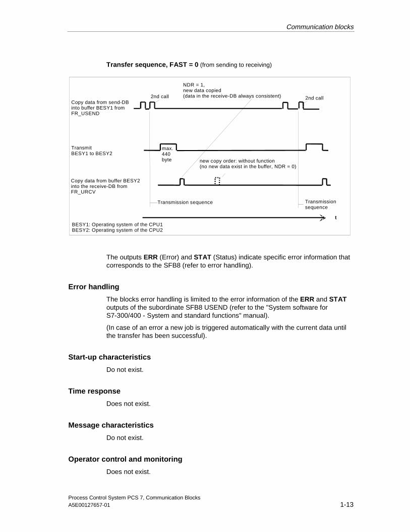
Transfer sequence, FAST = 0 (from sending to receiving)
Copy data from send-DBinto buffer BESY1 fromFR_USEND
NDR = 1,new data copied(data in the receive-DB always consistent)
new copy order: without function(no new data exist in the buffer, NDR = 0)
Transmission sequence
max.440byte
Transmissionsequence
BESY1: Operating system of the CPU1BESY2: Operating system of the CPU2
t
Copy data from buffer BESY2into the receive-DB fromFR_URCV
TransmitBESY1 to BESY2
2nd call 2nd call
The outputs ERR (Error) and STAT (Status) indicate specific error information thatcorresponds to the SFB8 (refer to error handling).
Error handling
The blocks error handling is limited to the error information of the ERR and STAToutputs of the subordinate SFB8 USEND (refer to the "System software forS7-300/400 - System and standard functions" manual).
(In case of an error a new job is triggered automatically with the current data untilthe transfer has been successful).
Start-up characteristics
Do not exist.
Time response
Does not exist.
Message characteristics
Do not exist.
Operator control and monitoring
Does not exist.
17.08.200117.08.2001
Communication blocks
Process Control System PCS 7, Communication Blocks1-14 A5E00127657-01
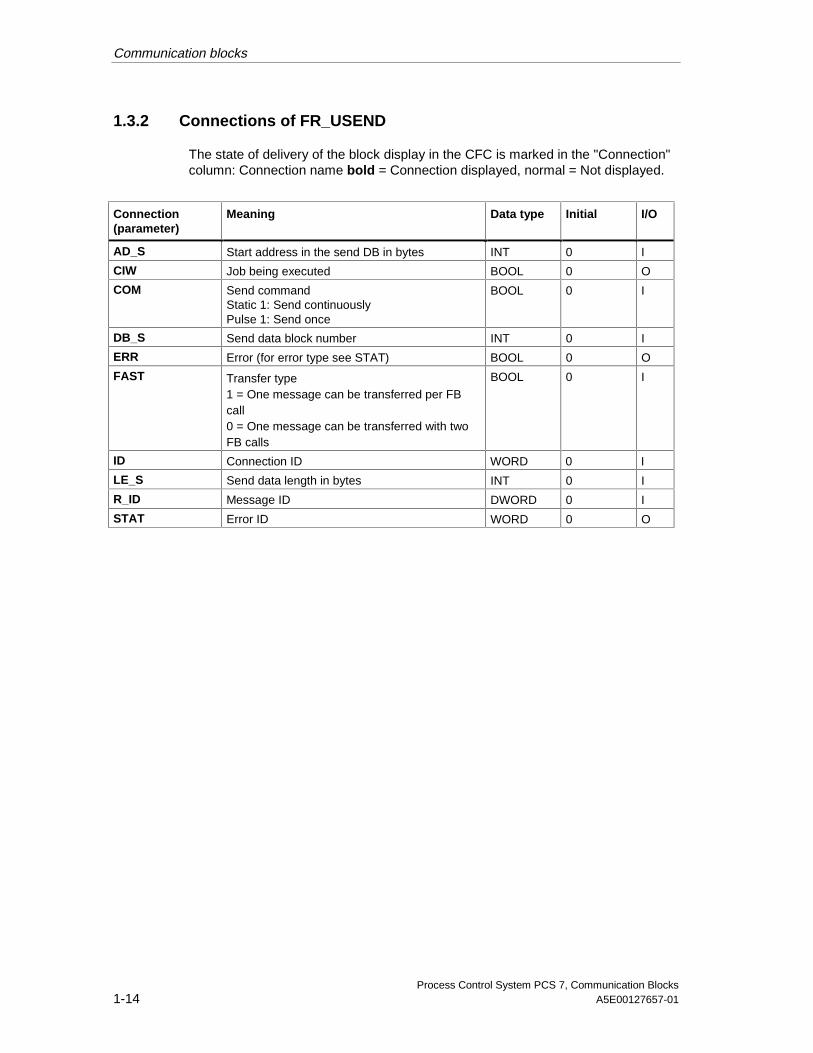
1.3.2 Connections of FR_USEND
The state of delivery of the block display in the CFC is marked in the "Connection"column: Connection name bold = Connection displayed, normal = Not displayed.
Connection(parameter)
Meaning Data type Initial I/O
AD_S Start address in the send DB in bytes INT 0 I
CIW Job being executed BOOL 0 O
COM Send commandStatic 1: Send continuouslyPulse 1: Send once
BOOL 0 I
DB_S Send data block number INT 0 I
ERR Error (for error type see STAT) BOOL 0 O
FAST Transfer type1 = One message can be transferred per FBcall0 = One message can be transferred with twoFB calls
BOOL 0 I
ID Connection ID WORD 0 I
LE_S Send data length in bytes INT 0 I
R_ID Message ID DWORD 0 I
STAT Error ID WORD 0 O
17.08.200117.08.2001
Communication blocks
Process Control System PCS 7, Communication BlocksA5E00127657-01 1-15
1.4 FR_URCV
1.4.1 FR_URCV: Call frame for URCV
Object name (Type + Number)
FB 204
Area of Application
The block forms a simple interface to the block SFB9 URCV for the user.
It receives data via an MPI, PROFIBUS or Ethernet connection from a further S7CPU (with MPI also M7-M7 or M7-S7) that has to call the function block type"USEND" (FC_USEND or SFB8 USEND) in order to receive the data. Only datablocks are allowed as data targets. In STEP7, a homogeneous transportconnection is to be installed on both sides and is to be transferred into theautomation device.
The FR_URCV can be used instead of the FR_BRCV if the data range is smallerthan 440 bytes, data consistency is required consistently across the complete senddata area and no secured transmission is demanded.
On "Data consistency": The data are constantly consistent in the receive DB (incontrast to the FR_BRCV). This is ensured by the fact that the data are alreadycopied completely and directly into the buffer - resp. from the buffer - of theoperating system when the function blocks FR_USEND and FR_UREC are calledby these function blocks. Inconsistency can only occur if the copy procedure isinterrupted by an interrupt program (corresponds to interruption of the subordinateSFB8 USEND or SFB9 URCV) and if the send/receive data are modified in theinterrupt program.
On "No secured transfer": In the case of FR_URCV/URCV the acknowledgment isgenerated on the operating-system-level without constant coordination with theuser program. This means that the acknowledgment is generated immediately afterthe data have arrived without waiting for the call of the receive block. The existenceof new receive data can be recognized by the fact that the signal changes to 1 atthe output NDR. If new receive data arrive before the block has been called, theseoverwrite the old data in the buffer. The value 9 is then output at the output STATat the next block call (refer to error handling).
Calling OBs
The watchdog interrupt OB into which the block is installed (for example OB35).
17.08.200117.08.2001

Communication blocks
Process Control System PCS 7, Communication Blocks1-16 A5E00127657-01
Operating principle
Send-DB
Buffer
Receive-DB
Transmitter Receiver
MPI, Ind.Ethernet,PROFIBUS
Function blockFR_USEND
Buffer
Operating system Operating system
Copydataconsistently
Function blockFR_URCV
max.440byte max. 440 byte
Acknowledgement
Sequence of a telegram
max. 440 byte
Order withID, R_ID,data length
Copydataconsistently
Order withID, R_ID,data length
A maximum of 440 bytes can be transported between the communication partnersby means of the SFB9 URCV used internally. The block must be called at leastonce (independently of the cycle) to carry out complete transfer of theparameterized data range. Entering the data into the user memory (corresponds tothe "Receive DB" in the figure above) is carried out synchronously to theprocessing of the user program. This means that he data are also consistent whenNDR equals 0. If the job has been completed without errors, the output NDR is setto 1 for one cycle.
The ID parameter is the connection number which is to be taken from theconnection configuration. It is only taken over at the first call after a cold restart.
The R_ID parameter is a random number (suggestion: message identification).However, it must be identical for the corresponding send and receive blocks. Theparameter is only taken over at the first call after a cold restart.
A call of the FR_URCV must be carried out for each ID/R_ID pair in each programcycle (cyclically or also via time interrupts)
The initial address of the target area of the received data is specified by DB_R(data block number) and AD_R (initial address in the receive DB in bytes). Theparameter LE_MAX specifies the maximum number of receivable data in bytes.
The outputs ERR (Error) and STAT (Status) indicate specific error information thatcorresponds to the SFB9 (refer to error handling).
17.08.200117.08.2001
Communication blocks
Process Control System PCS 7, Communication BlocksA5E00127657-01 1-17
Error handling
The blocks error handling is limited to the error information of the ERR and STAToutputs of the subordinate SFB9 URCV (refer to the "System software for S7-300/400 - System and standard functions" manual).
Start-up characteristics
Do not exist.
Time response
Does not exist.
Message characteristics
Do not exist.
Operator control and monitoring
Does not exist.
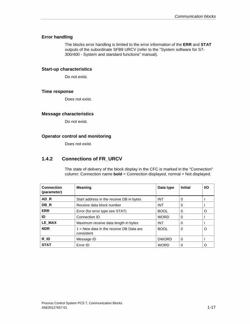
1.4.2 Connections of FR_URCV
The state of delivery of the block display in the CFC is marked in the "Connection"column: Connection name bold = Connection displayed, normal = Not displayed.
Connection(parameter)
Meaning Data type Initial I/O
AD_R Start address in the receive DB in bytes INT 0 I
DB_R Receive data block number INT 0 I
ERR Error (for error type see STAT) BOOL 0 O
ID Connection ID WORD 0 I
LE_MAX Maximum receive data length in bytes INT 0 I
NDR 1 = New data in the receive DB Data areconsistent
BOOL 0 O
R_ID Message ID DWORD 0 I
STAT Error ID WORD 0 O
17.08.200117.08.2001
Communication blocks
Process Control System PCS 7, Communication Blocks1-18 A5E00127657-01
1.5 FR_AGSEN
1.5.1 FR_AGSEN: Call frame for AG_SEND
Object name (Type + Number)
FB 205
Area of Application
The FB forms a simple interface to the block FC5 AG_SEND for the user. The FC5is integrated in the FB and therefore does not have to be loaded separately.
It sends data via a PROFIBUS CP443-5 Extended (FDL) or Industrial EthernetCP443-1 connection (ISO or ISO-on-TCP) to a further S7 CPU, an S5 CPU, aPC/programming device or an external device. At an S7-S7 connection the receiveside must call the block FR_AGRCV/AG_RCV in order to receive the data. Thereceive side in an S7-S5 connection must call the handling blocks RECEIVE. Onlydata blocks are allowed as data sources or data targets.
The FR_AGSEN can be used to transfer data with the CP443-1 or CP443-5Extended. It can transfer a maximum of 240 bytes per message unsecured andconsistently.
On "Data consistency": The data are constantly consistent in the receive DB. Thisis ensured by the fact that the data are already copied completely and directly intothe CP443 - resp. from the CP443 - when the function blocks FR_AGSEN andFR_AGRCV are called. Inconsistencies cannot arise because the subordinateblocks FC5 AG_SEND and FC6 AG_RCV cannot be interrupted by higher-priorityOBs.
On "No secured transfer": In the case of FR_AGRCV/AG_RCV theacknowledgment is generated on the operating-system-level without constantcoordination. This means that the acknowledgment also arrives at the FR_AGSENwhen the data could not be entered into the receive DB, for example when thereceive CPU is in STOP. The acknowledgment can be recognized by the fact thatthe signal changes to 0 at the output CIW.
Calling OBs
The watchdog interrupt OB into which the block is installed (for example OB35).
17.08.200117.08.2001
Communication blocks
Process Control System PCS 7, Communication BlocksA5E00127657-01 1-19
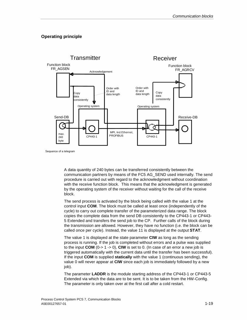
Operating principle
Send-DB
CP443-1
Receive-DB
Transmitter Receiver
MPI, Ind.Ethernet,PROFIBUS
Function blockFR_AGSEN
CP443-1
Operating system Operating system
Copydataconsistently
Function blockFR_AGRCV
max.240byte
Acknowledgement
Sequence of a telegram
Copydataconsistently
Order withID anddata length
Order withID anddata length
A data quantity of 240 bytes can be transferred consistently between thecommunication partners by means of the FC5 AG_SEND used internally. The sendprocedure is carried out with regard to the acknowledgment without coordinationwith the receive function block. This means that the acknowledgment is generatedby the operating system of the receiver without waiting for the call of the receiveblock.
The send process is activated by the block being called with the value 1 at thecontrol input COM. The block must be called at least once (independently of thecycle) to carry out complete transfer of the parameterized data range. The blockcopies the complete data from the send DB consistently to the CP443-1 or CP443-5 Extended and transfers the send job to the CP. Further calls of the block duringthe transmission are allowed. However, they have no function (i.e. the block can becalled once per cycle). Instead, the value 11 is displayed at the output STAT.
The value 1 is displayed at the state parameter CIW as long as the sendingprocess is running. If the job is completed without errors and a pulse was suppliedto the input COM (0-> 1 -> 0), CIW is set to 0. (In case of an error a new job istriggered automatically with the current data until the transfer has been successful).If the input COM is supplied statically with the value 1 (continuous sending), thevalue 0 will never appear at CIW since each job is immediately followed by a newjob).
The parameter LADDR is the module starting address of the CP443-1 or CP443-5Extended via which the data are to be sent. It is to be taken from the HW-Config.The parameter is only taken over at the first call after a cold restart.
17.08.200117.08.2001
Communication blocks
Process Control System PCS 7, Communication Blocks1-20 A5E00127657-01
The ID parameter is the connection number which is to be taken from theconnection configuration. It is only taken over at the first call after a cold restart.
The initial address of the data to be sent is specified by DB_S (data block number)and AD_S (byte start address in the send DB), the length of the data block in bytesby LE_S.
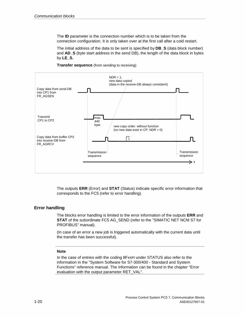
Transfer sequence (from sending to receiving)
NDR = 1,new data copied(data in the receive-DB always consistent)
new copy order: without function(no new data exist in CP: NDR = 0)
Transmissionsequence
max.440byte
Transmissionsequence
t
Copy data from send-DBinto CP1 fromFR_AGSEN
Copy data from buffer CP2into receive-DB fromFR_AGRCV
TransmitCP1 to CP2
The outputs ERR (Error) and STAT (Status) indicate specific error information thatcorresponds to the FC5 (refer to error handling).
Error handling
The blocks error handling is limited to the error information of the outputs ERR andSTAT of the subordinate FC5 AG_SEND (refer to the "SIMATIC NET NCM S7 forPROFIBUS" manual).
(In case of an error a new job is triggered automatically with the current data untilthe transfer has been successful).
Note
In the case of entries with the coding 8FxxH under STATUS also refer to theinformation in the "System Software for S7-300/400 - Standard and SystemFunctions" reference manual. The information can be found in the chapter "Errorevaluation with the output parameter RET_VAL".
17.08.200117.08.2001

Communication blocks
Process Control System PCS 7, Communication BlocksA5E00127657-01 1-21
Start-up characteristics
Do not exist.
Time response
Does not exist.
Message characteristics
Do not exist.
Operator control and monitoring
Does not exist.
1.5.2 Connections of FR_AGSEN
The state of delivery of the block display in the CFC is marked in the "Connection"column: Connection name bold = Connection displayed, normal = Not displayed.
Connection(parameter)
Meaning Data type Initial I/O
AD_S Start address in the send DB in bytes INT 0 I
CIW Job being executed BOOL 0 O
COM Send commandStatic 1: Send continuouslyPulse 1: Send once
BOOL 0 I
DB_S Send data block number INT 0 I
ERR Error (for error type see STAT) BOOL 0 O
ID Connection ID INT 0 I
LADDR CP module start address (in hex) WORD 0 I
LE_S Send data length in bytes INT 0 I
STAT Error ID WORD 0 O
17.08.200117.08.2001

Communication blocks
Process Control System PCS 7, Communication Blocks1-22 A5E00127657-01
1.6 FR_AGRCV
1.6.1 FR_AGRCV: Call frame for AG_RECV
Object name (Type + Number)
FB 206
Area of Application
The block forms a single interface to the block FC6 AG_RECV for the user. TheFC6 is integrated in the FB and therefore does not have to be loaded separately.
It receives data via a PROFIBUS (FDL) CP443-5 Extended or Industrial EthernetCP443-1 connection (ISO or ISO-on-TCP) from a further S7 CPU, an S5 CPU, aPC/programming device or an external device. At an S7-S7 connection the sendside must call the block FR_AGSEN/AG_SEND. The send side in an S7-S5connection must call the handling block SEND. Only data blocks are allowed asdata targets.
The FR_AGRCV can be used to transfer data with the CP443-1 or CP443-5Extended. It can transfer a maximum of 240 bytes per message unsecured andconsistently.
On "Data consistency": The data are constantly consistent in the receive DB. Thisis ensured by the fact that the data are already copied completely and directly intothe CP443 - resp. from the CP443 - when the function blocks FR_AGSEN andFR_AGRCV are called. Inconsistencies cannot arise because the subordinateblocks FC5 AG_SEND and FC6 AG_RCV cannot be interrupted by higher-priorityOBs.
On "No secured transfer": In the case of FR_AGRCV/AG_RCV theacknowledgment is generated on the operating-system-level without constantcoordination with the user program. This means that the acknowledgment isgenerated immediately after the data have arrived without waiting for the call of thereceive block. The existence of new receive data can be recognized by the fact thatthe signal changes to 1 at the output NDR.
Calling OBs
The watchdog interrupt OB into which the block is installed (for example OB35).
17.08.200117.08.2001

Communication blocks
Process Control System PCS 7, Communication BlocksA5E00127657-01 1-23
Operating principle
Send-DB
Buffer
Receive-DB
Transmitter Receiver
MPI, Ind.Ethernet,PROFIBUS
Function blockFR_AGSE
Buffer
Operating system Operating system
Copydataconsistently
Function blockF_AGRCV
max.440byte max. 440 byte
Acknowledgement
Sequence of a telegram
max. 440 byte
Order withID, R_ID,data length
Copydataconsistently
Order withID, R_ID,data length
A data quantity of 240 bytes can be transferred consistently between thecommunication partners by means of the FC6 AG_RECV used internally. Theblock must be called at least once (independently of the cycle) to carry outcomplete transfer of the parameterized data range. Entering the data into the usermemory (corresponds to the "Receive DB" in the figure above) is carried outsynchronously to the processing of the user program. This means that he data arealso consistent when NDR equals 0. If the job has been completed without errors,the output NDR is set to 1 for one cycle.
The parameter LADDR is the module starting address of the CP443-1 or CP443-5Extended via which the data are to be sent. It is to be taken from the HW-Config.The parameter is only taken over at the first call after a cold restart.
The ID parameter is the connection number which is to be taken from theconnection configuration. It is only taken over at the first call after a cold restart.
The initial address of the target area of the received data is specified by DB_R(data block number) and AD_R (initial address in the receive DB in bytes). Theparameter LE_R specifies the number of data received in bytes.
The outputs ERR (Error) and STAT (Status) indicate specific error information thatcorresponds to the FC6 (refer to error handling).
17.08.200117.08.2001
Communication blocks
Process Control System PCS 7, Communication Blocks1-24 A5E00127657-01
Error handling
The blocks error handling is limited to the error information of the ERR and STAToutputs of the subordinate FC6 AG_RECV (refer to the "SIMATIC NET NCM S7 forPROFIBUS" manual).
Note
In the case of entries with the coding 8FxxH under STATUS also refer to theinformation in the "System Software for S7-300/400 - Standard and SystemFunctions" reference manual. The information can be found in the chapter "Errorevaluation with the output parameter RET_VAL".
Start-up characteristics
Do not exist.
Time response
Does not exist.
Message characteristics
Do not exist.
Operator control and monitoring
Does not exist.
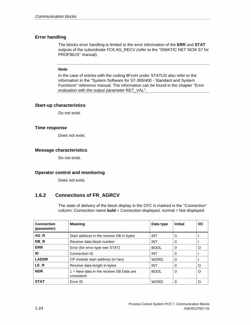
1.6.2 Connections of FR_AGRCV
The state of delivery of the block display in the CFC is marked in the "Connection"column: Connection name bold = Connection displayed, normal = Not displayed.
Connection(parameter)
Meaning Data type Initial I/O
AD_R Start address in the receive DB in bytes INT 0 I
DB_R Receive data block number INT 0 I
ERR Error (for error type see STAT) BOOL 0 O
ID Connection ID INT 0 I
LADDR CP module start address (in hex) WORD 0 I
LE_R Receive data length in bytes INT 0 O
NDR 1 = New data in the receive DB Data areconsistent
BOOL 0 O
STAT Error ID WORD 0 O
17.08.200117.08.2001
Communication blocks
Process Control System PCS 7, Communication BlocksA5E00127657-01 1-25
1.7 SEND_BO
1.7.1 SEND_BO: Send 128 BOOL values with BSEND
Object name (Type + Number)
FB 207
Area of Application
The block forms a simple interface to the block SFB12 BSEND for the user.
It sends up to 128 BOOL values via an MPI, PROFIBUS or Industrial Ethernetconnections to a further S7 CPU which has to call up the "REC_BO" (FB 208)function block type of the PCS7 Communication library in order to receive the data.
The data are not available consistently in the REC_BO until after the job has beencompleted (meaning after the acknowledgment DONE = TRUE has arrived). Theacknowledgment can be recognized by the fact that the signal changes to 0 at theoutput CIW.
If the parameter FAST is interconnected with 1, the FB allows the sending of onemessage per function block call possible, because it then internally calls the SFB12BSEND twice (the SFB12 requires an edge change from 0 to 1 at its control inputREQ to be activated). However, it is only advisable to use such frequent send jobassignment placing if there is enough time to transfer the message between twoFB calls.
Calling OBs
The watchdog interrupt OB into which the block is installed (for example OB35).
Operating principle
A maximum of 128 BOOL values can be transported between the communicationpartners by means of the SFB12 BSEND used internally. They are sent to thepartner by the operating system of the CPU where it is entered automatically intothe instance DB of the receiving FB (REC_BO) by the operating system. Beforethe new 128 BOOL values are sent, the system waits for the operating-systeminternal acknowledgment of the values just sent.
The send process is activated by the block being called with the value 1 at thecontrol input COM. The block must be called at least once (independently of thecycle) to carry out complete transfer of the data. The block transfers the job to theCPU operating system which carries out the job completely. Further calls of theblock with the same ID and the same R_ID during the transmission are allowed.
17.08.200117.08.2001
Communication blocks
Process Control System PCS 7, Communication Blocks1-26 A5E00127657-01
However, they have no function (i.e. the block can be called once per cycle).Instead, the value 11 is displayed at the output STAT. Reading of the data from theuser memory is carried out asynchronously to the processing of the user program.CIW is set to 0 if the job is terminated without errors. (In case of an error, ERR = 1,a new job is triggered automatically with the current data until the transfer has beensuccessful). If the value 0 is supplied to the input COM, a transfer which has notbeen completed yet is aborted and no longer sent. CIW is then equal to 0.
The ID parameter is the connection number which is to be taken from theconnection configuration. It is only taken over at the first call after a cold restart.
The R_ID parameter is a random number (suggestion: message identification).However, it must be identical for the corresponding send and receive blocks. Theparameter is only taken over at the first call after a cold restart.
If the value 1 is supplied to the parameter FAST, a new message can be sentwhenever the FB is called. The FB then internally calls the SFB12 BSEND twice,since the SFB12 requires an edge change from 0 to 1 at the control input REQ tobe activated. If the FB is called per cycle, then one message can be sent percycle. However, it is only advisable to use such frequent send job assignmentplacing if there is enough time to transfer the message between two FB calls. Inaddition using a frequent send job is only advisable if the call of the REC_BO in thereceive CPU is faster than that of the SEND_BO in the send CPU (the receive CPUrequires two calls (=2 cycles) for each message of the REC_BO).
If the value 0 is supplied to the parameter FAST, a new send job can only becarried out at every second FB call.
Error handling
The blocks error handling is limited to the error information of the subordinateSFB12 BSEND (refer to the "System software for S7-300/400 - System andstandard functions" manual). The outputs ERR and STAT are described there.
(In case of an error a new job is triggered automatically with the current data untilthe transfer has been successful).
Start-up characteristics
Do not exist.
Time response
Does not exist.
Message characteristics
Do not exist.
Operator control and monitoring
Does not exist.
17.08.200117.08.2001

Communication blocks
Process Control System PCS 7, Communication BlocksA5E00127657-01 1-27
1.7.2 Connections of SEND_BO
The state of delivery of the block display in the CFC is marked in the "Connection"column: Connection name bold = Connection displayed, normal = Not displayed.
Connection(parameter)
Meaning Data type Initial I/O
BO_00 Input_00 BOOL 0 I
...
BO_15 Input_15 BOOL 0 I
BO_16 Input_16 BOOL 0 I
... ... ...
BO_127 Input_127 BOOL 0 I
CIW 1 = Job being executed BOOL 0 O
COM 1 = Send Continuously, 0 = Do not send BOOL 1 I
DONE Command is Done BOOL 0 O
ERR Error (for error type see STAT) BOOL 0 O
FAST Transfer type:1 = One message can be transferred per FBcall0 = One message can be transferred with twoFB calls
BOOL 0 I
ID Connection ID WORD 0 I
R_ID Message ID DWORD 0 I
STAT Error ID WORD 0 O
17.08.200117.08.2001
Communication blocks
Process Control System PCS 7, Communication Blocks1-28 A5E00127657-01
1.8 REC_BO
1.8.1 REC_BO: Receive 128 BOOL values with BRCV
Object name (Type + Number)
FB 208
Area of Application
The block forms a simple interface to the block SFB13 BRCV for the user.
It receives 128 BOOL values via an MPI, PROFIBUS or Ethernet connections froma further S7 CPU which has to call up the "SEND_BO" function block type of thePCS7 Communication library (FB207) in order to send the data. In STEP7, ahomogeneous transport connection is to be installed on both sides and is to betransferred into the automation device.
The data are only available after the command has been completed at a signalchange of the NDR output from 0 to 1.
Calling OBs
The watchdog interrupt OB into which the block is installed (for example OB35).
Operating principle
A maximum of 128 BOOL values can be transported between the communicationpartners by means of the SFB13 BRCV used internally. The data are received bythe operating system of the CPU and entered in the instance DB of the receive FB(REC_BO). Before new data are received, an operating-system internalacknowledgment of the data just received has to be sent.
Entering the data in the data block is carried out asynchronously to the processingof the user program. After the REC_BO has been called, the data in the instanceDB may not be processed as long as the command is running (NDR = 0). If the jobhas been completed without errors, the output NDR is set to 1 for one cycle. In thesubsequent cycle the FB automatically provides the receive enable to the CPUoperating system (NDR is 0 again from and including this call).
The receive enable can already be effective before the first receive job arrives. Inthis case it is stored by the operating system.
The ID parameter is the connection number which is to be taken from theconnection configuration. It is only taken over at the first call after a cold restart.
17.08.200117.08.2001

Communication blocks
Process Control System PCS 7, Communication BlocksA5E00127657-01 1-29
The R_ID parameter is a random number (suggestion: message identification).However, it must be identical for the corresponding send and receive blocks. Theparameter is only taken over at the first call after a cold restart.
A call of the REC_BO must be carried out for each ID/R_ID pair in each programcycle (cyclically or also via time interrupts). Two calls of the REC_BO are requiredfor each message.
The outputs ERR (Error) and STAT (Status) indicate specific error information thatcorresponds to the SFB13 (refer to error handling).
In case of an error substitute values can optionally be output as received data(refer to error handling).
Error handling
The blocks error handling is limited to the error information of the subordinateSFB13 BRCV (refer to the "System software for S7-300/400 - System and standardfunctions" manual). The outputs ERR and STAT are described there.
If the input SUBS_ON = TRUE, substitute values are output at receipt errors orafter new data are not received after REC_MON (number of cycles).
Start-up characteristics
Do not exist.
Time response
Does not exist.
Message characteristics
Do not exist.
Operator control and monitoring
Does not exist.
17.08.200117.08.2001

Communication blocks
Process Control System PCS 7, Communication Blocks1-30 A5E00127657-01
1.8.2 Connections of REC_BO
The state of delivery of the block display in the CFC is marked in the "Connection"column: Connection name bold = Connection displayed, normal = Not displayed.
Connection(parameter)
Meaning Data type Initial I/O
ERR 1 = Error (for error type see STAT) BOOL 0 O
ID Connection ID WORD 0 I
NDR 1 = New Data Received BOOL 0 O
QNO_REC 1 = No Data Received BOOL 0 I
QSUBS_ON 1 = Substitute Values BOOL 0 I
R_ID Message ID DWORD 0 I
RD_BO_00 Received Value_00 BOOL 0 O
...
RD_BO_15 Received Value_15 BOOL 0 O
RD_BO_16 Received Value_16 BOOL 0 O
...
RD_BO_127 Received Value_127 BOOL 0 O
REC_MON Receive Monitoring (cycles) INT 3 I
STAT Error ID WORD 0 O
SUBBO_00 Substitute Value_00 BOOL 0 I
...
SUBBO_15 Substitute Value_15 BOOL 0 I
SUBBO_16 Substitute Value_16 BOOL 0 I
...
SUBBO127 Substitute Value_127 BOOL 0 I
SUBS_ON 1 = Substitute Values On by Error BOOL 0 I
17.08.200117.08.2001

Communication blocks
Process Control System PCS 7, Communication BlocksA5E00127657-01 1-31
1.9 SEND_R
1.9.1 SEND_R: Send 32 BOOL and 32 REAL values driven by changeswith BSEND
Object name (Type + Number)
FB 209
Area of Application
The block forms a simple interface to the block SFB12 BSEND for the user.
It sends up to 32 BOOL and 32 REAL values driven by changes via an MPI,PROFIBUS or Industrial Ethernet connections to a further S7 CPU which has tocall up the "REC_R" (FB 210) function block type of the PCS7 Communicationlibrary in order to receive the data.
The data are not available consistently in the REC_R until after the job has beencompleted (meaning after the acknowledgment DONE = TRUE has arrived). Theacknowledgment can be recognized by the fact that the signal changes to 0 at theoutput CIW.
If the parameter FAST is interconnected with 1, the FB allows the sending of onemessage per function block call possible, because it then internally calls the SFB12BSEND twice (the SFB12 requires an edge change from 0 to 1 at its control inputREQ to be activated). However, it is only advisable to use such frequent send jobassignment placing if there is enough time to transfer the message between twoFB calls.
Calling OBs
The watchdog interrupt OB into which the block is installed (for example OB35).
Operating principle
The 32 BOOL and 32 REAL input values are monitored for changes in comparisonto the last values sent successfully. At the REAL values a hysteresis (absolutevalue) is included in every check for changes. Transfers can be suppressed orforced by using the parameters EDC_MIN and EDC_MAX.
EDC_MIN specifies the number of cycles for which a trigger to send the currentinput data despite a change in one or more values.
17.08.200117.08.2001

Communication blocks
Process Control System PCS 7, Communication Blocks1-32 A5E00127657-01
EDC_MAX specifies the number of cycles of the last valid data transfer after whichthe current input data are to be sent, even if no value has changed or if the changein a REAL value lies with the hysteresis.
Observance of the theoretical time on the basis of the selected number of cyclescannot be ensured due to the acyclic data transfer between SEND_R and REC_R(see below).
A maximum of 32 BOOL values can be transported between the communicationpartners by means of the SFB12 BSEND used internally. They are sent to thepartner by the operating system of the CPU where it is entered automatically intothe instance DB of the receiving FB (REC_R) by the operating system. Before thenew values are sent, the system waits for the operating-system internalacknowledgment of the values just sent.
The send process is activated by the block being called with the value 1 at thecontrol input COM. The block must be called at least once (independently of thecycle) to carry out complete transfer of the data. The block transfers the job to theCPU operating system which carries out the job completely. Further calls of theblock with the same ID and the same R_ID during the transmission are allowed.However, they have no function (i.e. the block can be called once per cycle).Instead, the value 11 is displayed at the output STAT. Reading of the data from theuser memory is carried out asynchronously to the processing of the user program.CIW is set to 0 if the job is terminated without errors. (In case of an error, ERR = 1,a new job is triggered automatically with the current data until the transfer has beensuccessful). If the value 0 is supplied to the input COM, a transfer which has notbeen completed yet is aborted and no longer sent. CIW is then equal to 0.
The ID parameter is the connection number which is to be taken from theconnection configuration. It is only taken over at the first call after a cold restart.
The R_ID parameter is a random number (suggestion: message identification).However, it must be identical for the corresponding send and receive blocks. Theparameter is only taken over at the first call after a cold restart.
If the value 1 is supplied to the parameter FAST, a new message can be sentwhenever the FB is called. The FB then internally calls the SFB12 BSEND twice,since the SFB12 requires an edge change from 0 to 1 at the control input REQ tobe activated. If the FB is called per cycle, then one message can be sent percycle.
However, it is only advisable to use such frequent send job assignment placing if
1. There is enough time to transfer the message between two FB calls.
2. the call of the REC_R in the receive CPU is faster than that of the SEND_R inthe send CPU (the receive CPU requires two calls (=2 cycles) for eachmessage of the REC_R).
If the value 0 is supplied to the parameter FAST, a new send job can only becarried out at every second FB call.
17.08.200117.08.2001
Communication blocks
Process Control System PCS 7, Communication BlocksA5E00127657-01 1-33
Error handling
The blocks error handling is limited to the error information of the subordinateSFB12 BSEND (refer to the "System software for S7-300/400 - System andstandard functions" manual). The outputs ERR and STAT are described there.
(In case of an error a new job is triggered automatically with the current data untilthe transfer has been successful).
Start-up characteristics
Do not exist.
Time response
Does not exist.
Message characteristics
Do not exist.
Operator control and monitoring
Does not exist.
17.08.200117.08.2001

Communication blocks
Process Control System PCS 7, Communication Blocks1-34 A5E00127657-01
1.9.2 Connections of SEND_R
The state of delivery of the block display in the CFC is marked in the "Connection"column: Connection name bold = Connection displayed, normal = Not displayed.
Connection(parameter)
Meaning Data type Initial I/O
BO_00 BOOL-Input_00 BOOL 0 I
...
BO_07 BOOL-Input_07 BOOL 0 I
BO_08 BOOL-Input_08 BOOL 0 I
...
BO_31 BOOL-Input_31 BOOL 0 I
CIW 1 = Job being executed BOOL 0 O
COM 1 = Send Continuously, 0 = Do not send BOOL 1 I
DONE 1 = Command is Done BOOL 0 O
EDC_MAX Forced transfer after n cycles without change INT 10 I
EDC_MIN Earliest transfer after n cycles at a change INT 1 I
ERR Error (for error type see STAT) BOOL 0 O
FAST Transfer type:1 = One message can be transferred per FBcall0 = One message with 2 FB calls can betransferred
BOOL 0 I
ID Connection ID WORD 0 I
R_00 REAL-Input_00 REAL 0 I
...
R_07 REAL-Input_07 REAL 0 I
R_08 REAL-Input_08 REAL 0 I
...
R_31 REAL-Input_31 REAL 0 I
R_ID Message ID DWORD 0 I
STAT Error ID WORD 0 O
17.08.200117.08.2001

Communication blocks
Process Control System PCS 7, Communication BlocksA5E00127657-01 1-35
1.10 REC_R
1.10.1 REC_R: Receive 32 BOOL and 32 REAL values with BRCV
Object name (Type + Number)
FB 210
Area of Application
The block forms a simple interface to the block SFB13 BRCV for the user.
It receives 32 BOOL and 32 REAL values via an MPI, PROFIBUS or Ethernetconnection from a further S7 CPU which has to call up the "SEND_R" functionblock type of the PCS7 Communication library (FB209) in order to send the data. InSTEP7, a homogeneous transport connection is to be installed on both sides andis to be transferred into the automation device.
The data are only available after the command has been completed at a signalchange of the NDR output from 0 to 1.
Calling OBs
The watchdog interrupt OB into which the block is installed (for example OB35).
Operating principle
A maximum of 32 BOOL and 32 REAL values can be transported between thecommunication partners by means of the SFB13 BRCV used internally. The dataare received by the operating system of the CPU and entered in the instance DB ofthe receive FB (REC_R). Before new data are received, an operating-systeminternal acknowledgment of the data just received has to be sent.
Entering the data in the data block is carried out asynchronously to the processingof the user program. After the REC_R has been called, the data in the instance DBmay not be processed as long as the command is running (NDR = 0). If the job hasbeen completed without errors, the output NDR is set to 1 for one cycle. In thesubsequent cycle the FB automatically provides the receive enable to the CPUoperating system (NDR is 0 again from and including this call).
The receive enable can already be effective before the first receive job arrives. Inthis case it is stored by the operating system.
The ID parameter is the connection number which is to be taken from theconnection configuration. It is only taken over at the first call after a cold restart.
17.08.200117.08.2001

Communication blocks
Process Control System PCS 7, Communication Blocks1-36 A5E00127657-01
The R_ID parameter is a random number (suggestion: message identification).However, it must be identical for the corresponding send and receive blocks. Theparameter is only taken over at the first call after a cold restart.
A call of the REC_R must be carried out for each ID/R_ID pair in each programcycle (cyclically or also via time interrupts). Two calls of the REC_R are requiredfor each message.
The outputs ERR (Error) and STAT (Status) indicate specific error information thatcorresponds to the SFB13 (refer to error handling).
In case of an error substitute values can optionally be output as received data(refer to error handling).
Error handling
The blocks error handling is limited to the error information of the subordinateSFB13 BRCV (refer to the "System software for S7-300/400 - System and standardfunctions" manual). The outputs ERR and STAT are described there.
If the input SUBS_ON = TRUE, substitute values are output at receipt errors orafter new data are not received after REC_MON (number of cycles).
Start-up characteristics
Do not exist.
Time response
Does not exist.
Message characteristics
Do not exist.
Operator control and monitoring
Does not exist.
17.08.200117.08.2001

Communication blocks
Process Control System PCS 7, Communication BlocksA5E00127657-01 1-37
1.10.2 Connections of REC_R
The state of delivery of the block display in the CFC is marked in the "Connection"column: Connection name bold = Connection displayed, normal = Not displayed.
Connection(parameter)
Meaning Data type Initial I/O
ERR 1 = Error (for error type see STAT) BOOL 0 O
ID Connection ID WORD 0 I
NDR 1 = New Data Received BOOL 0 O
QNO_REC 1 = No Data Received BOOL 0 I
QSUBS_ON 1 = Substitute Values BOOL 0 I
R_ID Message ID DWORD 0 I
RD_BO_00 Received BOOL Value 00 BOOL 0 O
...
RD_BO_07 Received BOOL Value 07 BOOL 0 O
RD_BO_08 Received BOOL Value 08 BOOL 0 O
...
RD_BO_31 Received BOOL Value 31 BOOL 0 O
RD_R_00 Received REAL Value_00 REAL 0 O
...
RD_R_07 Received REAL Value_07 REAL 0 O
RD_R_08 Received REAL Value_08 REAL 0 O
...
RD_R_31 Received REAL Value_31 REAL 0 O
REC_MON Receive Monitoring (cycles) INT 3 I
STAT Error ID WORD 0 O
SUBBO_00 Substitute BOOL Value_00 BOOL 0 I
...
SUBBO_07 Substitute BOOL Value_07 BOOL 0 I
SUBBO_08 Substitute BOOL Value_08 BOOL 0 I
...
SUBBO_31 Substitute BOOL Value_31 BOOL 0 I
SUBR_00 Substitute REAL Value_00 REAL 0 I
...
SUBR_07 Substitute REAL Value_07 REAL 0 I
SUBR_08 Substitute REAL Value_08 REAL 0 I
...
SUBR_31 Substitute REAL Value_31 REAL 0 I
SUBS_ON 1 = Substitute Values On by Error BOOL 0 I
17.08.200117.08.2001

Communication blocks
Process Control System PCS 7, Communication Blocks1-38 A5E00127657-01
17.08.200117.08.2001

Process Control System PCS 7, Communication BlocksA5E00127657-01 Index-1
Index
CCall frame for AG_RCV (FR_AGRCV) .........1-22Call frame for AG_SEND (FR_AGSEN) .......1-18Call frame for BRCV (FR_BRCV)...................1-6Call frame for URCV (FR_URCV) ................1-15Call frame for USEND (FR_USEND)............1-10Connections of FR_AGRCV.........................1-24Connections of FR_AGSEN .........................1-21Connections of FR_BRCV..............................1-9Connections of FR_BSEND ...........................1-5Connections of FR_URCV ...........................1-17Connections of FR_USEND .........................1-14Connections of REC_BO..............................1-30Connections of REC_R ................................1-37Connections of SEND_BO ...........................1-27Connections of SEND_R..............................1-34
FFR_AGRCV.........................................1-22, 1-24
Connections .............................................1-24FR_AGSEN.........................................1-18, 1-21
Connections .............................................1-21FR_BRCV ................................ 1-6, 1-7, 1-8, 1-9
Connections ...............................................1-9FR_BSEND ....................................................1-5
Call frame for BSEND (FR_BSEND) ......... 1-1Connections............................................... 1-5
FR_URCV.................................. 1-15, 1-16, 1-17Connections............................................. 1-17
FR_USEND ........................................ 1-10, 1-14Connections............................................. 1-14
RREC_BO.................................... 1-28, 1-29, 1-30
Connections............................................. 1-30REC_R....................................... 1-35, 1-36, 1-37
Connections............................................. 1-37REC_R Receive 32 BOOL and
32 REAL values with BRCV..................... 1-35Receive 128 BOOL values with BRCV
(REC_BO)................................................ 1-28
SSend 128 BOOL values with BSEND
(SEND_BO) ............................................. 1-25Send 32 BOOL and 32 REAL values
driven by changes with BSEND............... 1-31SEND_BO........................................... 1-26, 1-27
Connections............................................. 1-27SEND_R ............................................. 1-32, 1-34
Connections............................................. 1-34
17.08.200117.08.2001

Index
Process Control System PCS 7, Communication BlocksIndex-2 A5E00127657-01
17.08.200117.08.2001