process control system pcs 7 getting started - part 2 · pdf fileprocess control system pcs 7,...
TRANSCRIPT
s
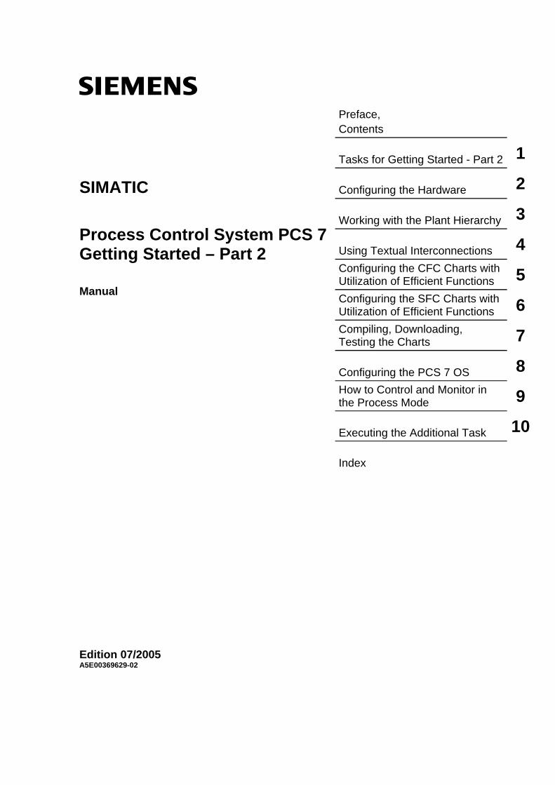
Preface, Contents Tasks for Getting Started - Part 2 1 Configuring the Hardware 2 Working with the Plant Hierarchy 3 Using Textual Interconnections 4Configuring the CFC Charts with Utilization of Efficient Functions 5Configuring the SFC Charts with Utilization of Efficient Functions 6Compiling, Downloading, Testing the Charts 7 Configuring the PCS 7 OS 8How to Control and Monitor in the Process Mode 9 Executing the Additional Task 10 Index
SIMATIC
Process Control System PCS 7 Getting Started – Part 2 Manual
Edition 07/2005 A5E00369629-02
Copyright Siemens AG 2005 All rights reserved The reproduction, transmission or use of this document or its contents is not permitted without express written authority. Offenders will be liable for damages. All rights, including rights created by patent grant or registration of a utility model or design, are reserved. Siemens AG Bereich Automation and Drives Geschaeftsgebiet Industrial Automation Systems Postfach 4848, D- 90327 Nuernberg
Disclaimer of Liability We have checked the contents of this manual for agreement withthe hardware and software described. Since deviations cannot beprecluded entirely, we cannot guarantee full agreement. However,the data in this manual are reviewed regularly and any necessarycorrections included in subsequent editions. Suggestions forimprovement are welcomed. Siemens AG 2005 Technical data subject to change.
Siemens Aktiengesellschaft A5E00369629-02
Safety Guidelines
This manual contains notices intended to ensure personal safety, as well as to protect the products and connected equipment against damage. These notices are highlighted by the symbols shown below and graded according to severity by the following texts:
! Danger indicates that death, severe personal injury or substantial property damage will result if proper precautions are not taken.
! Warning indicates that death, severe personal injury or substantial property damage can result if proper precautions are not taken.
! Caution indicates that minor personal injury can result if proper precautions are not taken.
Caution
indicates that property damage can result if proper precautions are not taken.
Notice draws your attention to particularly important information on the product, handling the product, or to a particular part of the documentation.
Qualified Personnel
Only qualified personnel should be allowed to install and work on this equipment. Qualified persons are defined as persons who are authorized to commission, to ground and to tag circuits, equipment, and systems in accordance with established safety practices and standards.
Correct Usage
Note the following:
! Warning This device and its components may only be used for the applications described in the catalog or the technical description, and only in connection with devices or components from other manufacturers which have been approved or recommended by Siemens. This product can only function correctly and safely if it is transported, stored, set up, and installed correctly, and operated and maintained as recommended.
Trademarks
SIMATIC®, SIMATIC HMI® and SIMATIC NET® are registered trademarks of SIEMENS AG.
Third parties using for their own purposes any other names in this document which refer to trademarks might infringe upon the rights of the trademark owners.

Process Control System PCS 7, Getting Started - Part 2 A5E00369629-02 iii
Preface
Purpose of the Manual Getting Started – Part 2 introduces the PCS 7 functions you can use for fast and effective configuration of you plant. These functions are especially convenient for configuring large, complex plants.
Getting Started – Part 2 is especially directed at users who have already worked through Getting Started – Part 1.
Required Experience You should already have experience in the following areas:
• Microsoft operating system Windows 2000, Windows XP
• Basic knowledge in the field of process automation
• Functions and configuration of SIMATIC S7 (S7-400, STEP 7)
• Functions and configuration of SIMATIC NET (network components, transmission media)
You should also be familiar with the basic functions of PCS 7. This includes all functions described in Getting Started – Part 1. Detailed instructions are provided for all functions that were not covered in the first part of Getting Started – Part 1. You should read the detailed descriptions in Getting Started – Part 1 again if necessary.
Scope of the Manual The manual applies to "PCS 7 Engineering Toolset V 6.1".

Preface
Process Control System PCS 7, Getting Started - Part 2 iv A5E00369629-02
Guide to the Manual Getting Started – Part 2 is based on Getting Started – Part 1. In this Getting Started, you will configure an additional unit of the paint project. You will become familiar with functions for efficient engineering. You will find important background information needed to understand the individual topics and, of course, perform step-by-step configuration.
You are also provided with a completed "color_gs2.zip" project as a sample project in a file. This is installed along with the system documentation of PCS 7. You can open this project on an existing engineering system (ES) to view the configuration data and compare the data with your own configuration data. You can activate the project on an operator station (OS) to control and monitor the process.
Note
To test the sample project in process mode, you may have to adapt the hardware configuration of the project to your actual hardware. In other words, you may have to replace the hardware components in the sample project with you existing hardware components.
Note
Many preparatory tasks that you will do in Getting Started – Part 2 were already described in Getting Started – Part 1. Therefore, they are only described in outline form in this part of Getting Started. Refer to Getting Started – Part 1 if you require detailed information. This is part of the system documentation for PCS 7 that is included in the standard installation of PCS 7.
Select the following menu command to open Getting Started – Part 1:
Start > Simatic > Documentation > English > PCS 7 Getting Started Part 1 (Online Help) or PCS 7 Getting Started Part 1 (PDF)

Preface
Process Control System PCS 7, Getting Started - Part 2 A5E00369629-02 v
Conventions In this Getting Started, all the instructions are explained with full menu commands. You can also activate the majority of functions from context menus or by double-clicking on an icon.
In PCS 7, you can use standard Windows functions in many situations:
• Multiple selection with the "CTRL" and "Shift" keys
• Sorting columns in tables by clicking on the column header
• Using Drag & Drop instead of Copy and Paste
If you open the HTML version of Getting Started, you can run video sequences. These video sequences show the exact steps that you can follow on screen before performing them yourself. Video sequences are indicated by the following icon:
Video
Click on the word "Video" to start a video sequence. You can pause and restart the video sequences using the corresponding commands in the context menu.
One tutorial in Getting Started leads to the next and you will create a complete PCS 7 project yourself step-by-step. This makes it essential to work through the tutorials in the correct order.
Special Notes You will find more detailed information and wide-ranging topics in the configuration manuals "Process Control System PCS 7, Engineering System" and "Process Control System PCS 7, Operator Station". These will be useful to you as references.
These manuals are located
• as PDF files on the DVD "PCS 7 Engineering Toolset V6.1"
• in the PCS 7 Software in the SIMATIC Manager. You can open the documents with the menu command "Start > SIMATIC > Documentation > [required language]".
If you wish to familiarize yourself with the special topics in greater depth, refer to the appropriate manuals, for example, for SFC and CFC.

Preface
Process Control System PCS 7, Getting Started - Part 2 vi A5E00369629-02
Further Support If you have any technical questions, please get in touch with your Siemens representative or agent responsible.
You will find your contact person at:
http://www.siemens.com/automation/partner
You will find a guide to the technical documentation offered for the individual SIMATIC Products and Systems here at:
http://www.siemens.com/simatic-tech-doku-portal
The online catalog and order system is found under:
http://mall.automation.siemens.com/
Training Centers Siemens offers a number of training courses to familiarize you with the Process Control System PCS 7. Please contact your regional training center or our central training center in D 90327 Nuremberg, Germany for details: Telephone: +49 (911) 895-3200. Internet: http://www.sitrain.com

Preface
Process Control System PCS 7, Getting Started - Part 2 A5E00369629-02 vii
Technical Support You can reach the Technical Support for all A&D products
• Via the Web formula for the Support Request http://www.siemens.com/automation/support-request
• Phone: + 49 180 5050 222
• Fax: + 49 180 5050 223
Additional information about our Technical Support can be found on the Internet pages http://www.siemens.com/automation/service
Service & Support on the Internet In addition to our documentation, we offer our Know-how online on the internet at: http://www.siemens.com/automation/service&support
where you will find the following:
• The newsletter, which constantly provides you with up-to-date information on your products.
• The right documents via our Search function in Service & Support.
• A forum, where users and experts from all over the world exchange their experiences.
• Your local representative for Automation & Drives.
• Information on field service, repairs, spare parts and more under "Services".

Preface
Process Control System PCS 7, Getting Started - Part 2 viii A5E00369629-02

Process Control System PCS 7, Getting Started - Part 2 A5E00369629-02 ix
Contents
1 Tasks for Getting Started - Part 2 1-1 1.1 Requirements for Working through Getting Started ......................................... 1-1 1.1.1 Requirements for Performing Getting Started - Part 2 ..................................... 1-1 1.1.2 Required Hardware for Getting Started - Part 2 ............................................... 1-1 1.1.3 Required Software for Getting Started ............................................................. 1-2 1.2 Introduction to the Project for Getting Started .................................................. 1-3 1.2.1 Structure of the Plant for the 'color_gs' Project ................................................ 1-3 1.2.2 Introduction to the Overall Project .................................................................... 1-4 1.2.3 Tasks Definitions for Getting Started - Part 2 ................................................... 1-7 1.3 Executing the Preparatory Tasks ..................................................................... 1-8 1.3.1 Overview of Default Settings ............................................................................ 1-8 1.3.1.1 How to Make the Settings in the Configuration Console .................................. 1-9 1.3.1.2 How to Select the Communication Module in SIMATIC Shell ........................ 1-10 1.3.1.3 How to Retrieve the Project............................................................................ 1-10 1.3.1.4 How to Adapt the AS Configuration................................................................ 1-11 1.3.1.5 How to Rename the PC Station...................................................................... 1-12 1.3.1.6 How to Adapt the Name of the OS ................................................................. 1-13 1.3.1.7 How to Adapt the OS Configuration ............................................................... 1-14 1.3.1.8 How to Make the Settings in NetPro............................................................... 1-15
2 Configuring the Hardware 2-1 2.1 Simulation Principle using Hardware Components .......................................... 2-1 2.1.1 Implementing Simulation with Hardware .......................................................... 2-1 2.1.1.1 How to Change the Name of the Plant Bus...................................................... 2-2 2.1.1.2 How to Add the Distributed I/O ......................................................................... 2-3 2.2 Function and Use of Symbolic Names ............................................................. 2-5 2.2.1 Using Symbolic Names..................................................................................... 2-5 2.2.2 Symbolic Names for Digital Input Modules....................................................... 2-6 2.2.3 Symbolic Names for Digital Output Modules .................................................... 2-6 2.2.4 Symbolic Names for Analog Input Modules...................................................... 2-7 2.2.5 Symbolic Names for Analog Output Modules................................................... 2-7 2.2.5.1 How to Assign Symbolic Names....................................................................... 2-8
3 Working with the Plant Hierarchy 3-1 3.1 Adapting the Plant Hierarchy............................................................................ 3-1 3.1.1 How to Expand the Plant Hierarchy.................................................................. 3-2 3.1.2 How to Add Process Pictures ........................................................................... 3-3
4 Using Textual Interconnections 4-1 4.1 What are Textual Interconnections?................................................................. 4-1 4.2 Textual Interconnections in CFC Charts........................................................... 4-2 4.3 Textual Interconnections in SFC Charts........................................................... 4-2

Contents
Process Control System PCS 7, Getting Started - Part 2 x A5E00369629-02
5 Configuring the CFC Charts with Utilization of Efficient Functions 5-1 5.1 Overview of the Work in CFC ........................................................................... 5-1 5.2 Expanding the Master Data Library .................................................................. 5-1 5.2.1 How to Save Additional Blocks......................................................................... 5-2 5.3 Simulation Charts and the Chart-in-Chart Technique ...................................... 5-3 5.3.1 Implementing Simulation with CFC Charts....................................................... 5-3 5.3.2 Function of the Simulation Charts .................................................................... 5-3 5.3.3 Function of the "General" CFC Chart ............................................................... 5-4 5.3.3.1 How to Insert CFC charts for REAC1............................................................... 5-5 5.3.3.2 How to Create the "General" Chart .................................................................. 5-6 5.3.3.3 How to Create the "SIMV" Chart ...................................................................... 5-7 5.3.3.4 Step 1 - How to Insert the "SIMV" Block........................................................... 5-8 5.3.3.5 Step 2 - How to Configure the Inputs and Outputs of "SIMV" .......................... 5-9 5.3.3.6 Step 3 - How to Interconnect the Inputs and Outputs of "SIMV" .................... 5-10 5.3.3.7 How to Create the "SIMMO" Chart ................................................................. 5-12 5.3.3.8 How to Create the "SIMREAC" Simulation Chart ........................................... 5-14 5.4 Working with Process Tag Types ................................................................... 5-18 5.4.1 Using Process Tag Types............................................................................... 5-18 5.4.2 How to Create the Process Tag 'MOTOR' ..................................................... 5-19 5.4.2.1 Step 1 - How to Create the "TYPE_MOTOR" Base Chart ............................. 5-19 5.4.2.2 Step 2 - How to Create the "TYPE_MOTOR" Process Tag Type .................. 5-21 5.4.2.3 Step 3 - How to Create the Import File "MOTOR_REAC1"............................ 5-25 5.4.2.4 Step 4 - Editing the Import File "MOTOR_REAC1"........................................ 5-27 5.4.2.5 Step 5 - How to Generate "TYPE_MOTOR" Process Tags ........................... 5-31 5.4.2.6 The Results..................................................................................................... 5-33 5.4.3 How to Create "VALVE" Process Tags Using Process Tag Types................ 5-34 5.4.3.1 Step 1 - How to Create the "TYPE_VALVE" Base Chart ............................... 5-35 5.4.3.2 Step 2 - How to Create the "TYPE_VALVE" Process Tag Type.................... 5-37 5.4.3.3 Step 3 - How to Create the Import File "VALVE_REAC1".............................. 5-38 5.4.3.4 Step 4 - Editing the Import File "VALVE_REAC1".......................................... 5-39 5.4.3.5 Step 5 - Generating "TYPE_VALVE" Process Tags ...................................... 5-41 5.4.3.6 How to Close Textual Interconnections... ....................................................... 5-42 5.5 Modifying Process Tag Types ........................................................................ 5-44 5.5.1 Making Changes at a Later Time ................................................................... 5-44 5.5.2 The Most Important Information about the Import/Export File........................ 5-44 5.5.2.1 How to Add a Parameter ................................................................................ 5-45 5.5.2.2 Making Additional Corrections - Basic Procedure .......................................... 5-48 5.6 Creating Additional CFC Charts ..................................................................... 5-50 5.6.1 How to Create a "CFC_LI311" CFC Chart ..................................................... 5-50 5.6.2 How to Create the "CFC Chart TC 311" CFC Chart....................................... 5-53 5.7 Summary ........................................................................................................ 5-57 5.7.1 Summary of "Efficient Engineering in the CFC Configuration"....................... 5-57

Contents
Process Control System PCS 7, Getting Started - Part 2 A5E00369629-02 xi
6 Configuring the CFC Charts with Utilization of Efficient Functions 6-1 6.1 Overview of the Work in SFC ........................................................................... 6-1 6.2 Modifing the SFC Charts in the 'RMT1/2' Parts of Plant .................................. 6-1 6.2.1 Modifications in the RMT Parts of Plant ........................................................... 6-1 6.2.1.1 How to Modify the SFC Charts of the RMTx Part of Plant ............................... 6-2 6.3 Working with SFC Types .................................................................................. 6-5 6.3.1 Overview of SFC Types.................................................................................... 6-5 6.3.2 What are the Important Elements in an SFC Type?......................................... 6-6 6.3.3 Planning for the "REAC" SFC Type.................................................................. 6-7 6.3.3.1 How to Create an SFC Type ............................................................................ 6-9 6.3.3.2 Step 1 - How to Create an SFC Type............................................................... 6-9 6.3.3.3 Step 2 - How to Open the SFC Type "REAC" ................................................ 6-10 6.3.3.4 Step 3 - How to Define the Control Strategies ............................................... 6-11 6.3.3.5 Step 4 - How to Create the Sequences.......................................................... 6-13 6.3.3.6 Step 5 - How to Specify the Setpoints ............................................................ 6-15 6.3.3.7 Step 6 - How to Create Process Values......................................................... 6-17 6.3.3.8 Step 7 - How to Create the Block Contacts .................................................... 6-18 6.3.3.9 Step 8 - How to Configure the "RESET" Sequence ....................................... 6-20 6.3.3.10 Step 9 - How to Configure the "Heating" and "Drain" Sequences.................. 6-23 6.3.3.11 Step 10 - How to Create an SFC Instance ..................................................... 6-25 6.3.3.12 Step 11 - How to Save the SFC Type in the Master Data Library.................. 6-27 6.4 Summary ........................................................................................................ 6-28 6.4.1 Summary of "Efficient Engineering in the SFC Configuration" ....................... 6-28
7 Compiling, Downloading, Testing the Charts 7-1 7.1 Compiling, Downloading and Testing Your Project .......................................... 7-1 7.1.1 How to Compile and Download the Project ...................................................... 7-1 7.1.2 How to Test the Program.................................................................................. 7-5
8 Configuring the PCS 7 OS 8-1 8.1 Overview of Work Involving the OS Configuration ........................................... 8-1 8.2 Creating Graphic Symbols................................................................................ 8-2 8.2.1 Creation of Custom Symbols for Process Pictures .......................................... 8-2 8.2.1.1 How to Open a Picture File for Your Symbols.................................................. 8-2 8.2.1.2 How to Create the Symbols for the Agitator ..................................................... 8-3 8.2.1.3 How to Create the Symbols for the Pump ........................................................ 8-6 8.3 Working with Standard Block Symbols............................................................. 8-8 8.3.1 Where are the Standard Block Icons Saved?................................................... 8-8 8.3.2 Modifying the Standard Block Icons ................................................................. 8-9 8.3.2.1 Creating a New Template File ........................................................................ 8-10 8.3.2.2 How to Modify the Standard Block Icons........................................................ 8-10 8.3.2.3 Step 1 - Saving a Copy of the Required Block Icon ....................................... 8-11 8.3.2.4 Step 2 - How to Change the Properties of the "MOTOR" Block Icon............. 8-11 8.3.2.5 Step 3 - How to Adapt the Representation of the Pump ................................ 8-12 8.3.2.6 Step 4 - How to Modify the "SFC TYPE" Block Icon ...................................... 8-13 8.4 Generate Block Icons and Compile the OS.................................................... 8-16 8.4.1 How to Activate the Option for Generating Block Icons ................................. 8-16 8.4.1.1 How to Generate the Block Icons ................................................................... 8-17 8.4.1.2 How to Compile the OS .................................................................................. 8-19 8.5 Creating the Process Picture.......................................................................... 8-21 8.5.1 How to Create the Process Picture ................................................................ 8-21 8.5.2 How to Insert a Status Display ....................................................................... 8-24 8.5.2.1 Inserting Buttons for RMT1 and RMT2........................................................... 8-27 8.5.3 How to Modify the Process Pictures RMT1 and RMT2.................................. 8-30 8.6 Summary ........................................................................................................ 8-31 8.6.1 Summary of "Efficient Engineering in the OS Configuration" ......................... 8-31

Contents
Process Control System PCS 7, Getting Started - Part 2 xii A5E00369629-02
9 How to Control and Monitor in the Process Mode 9-1 9.1 Functions in Process Mode .............................................................................. 9-1 9.2 Operating the SFC Instance ............................................................................. 9-1 9.2.1 How to Start the SFC Instance ......................................................................... 9-2 9.2.2 How to Select the Control Strategy .................................................................. 9-3 9.2.3 How to Change the Setpoint for the Temperature............................................ 9-4 9.2.4 How to Switch the Simulation Mode ................................................................. 9-5 9.2.5 How to Specify the Minimum Fill Level............................................................. 9-5
10 Executing the Additional Task 10-1 10.1 Configuring Reactor 2 at a Glance ................................................................. 10-1 10.1.1 How to Configure the "REAC2" Part of Plant ................................................. 10-1 10.1.2 How to Compile the Changes......................................................................... 10-4
Index Index-1

Process Control System PCS 7, Getting Started - Part 2 A5E00369629-02 1-1
1 Tasks for Getting Started - Part 2
1.1 Requirements for Working through Getting Started
1.1.1 Requirements for Performing Getting Started - Part 2
In order to perform Getting Started, certain requirements must be met for the following components:
• Hardware
• Software
1.1.2 Required Hardware for Getting Started - Part 2
The required hardware corresponds to that required for Getting Started – Part 1. The required hardware components are briefly listed in the following tables:
Hardware components Equipment for Getting Started Other variants
possible
PG or PC with standard network card
3Com EtherLink III IS yes
Rack UR2 yes Power supply PS 407 10A yes CPU CPU 417-4, Firmware as of V 3.1 no CP 443-1 6GK7 443-1 EX11-0XE0,
Firmware as of 2.0 with a fixed MAC address
no
Memory card Crossover cable no
Caution
The CPU and CP are mandatory to perform configuration tasks as described in Getting Started.
Note
If you need more detailed information about the hardware required, refer to Getting Started – Part 1.

Tasks for Getting Started - Part 2
Process Control System PCS 7, Getting Started - Part 2 1-2 A5E00369629-02
If you wish to perform a concrete simulation of the I/O modules, you will also need the following components:
Hardware components Equipment for Getting Started Other variants possible
IM 153-1 6ES7 153-1AA03-0XB0 yes Digital input module 6ES7 321-1BH01-0AA0 yes
Digital output module 6ES7 322-8BF00-0AB0 yes
Analog input module 6ES7 331-7KF01-0AB0 yes
Analog output module 6ES7 332-5HD01-0AB0 yes
1.1.3 Required Software for Getting Started
The following software must be installed in any case:
• Windows XP Professional, Windows 2000 Professional
• Internet Explorer 6.0
• Message queuing service
• SQL Server
• Software package "PCS 7 Engineering" – if you have questions about the installation of the PCS 7 Toolset, please refer to the readme file on the installation DVD or contact Customer Support.

Tasks for Getting Started - Part 2
Process Control System PCS 7, Getting Started - Part 2 A5E00369629-02 1-3
1.2 Introduction to the Project for Getting Started
1.2.1 Structure of the Plant for the 'color_gs' Project
The plant structure for Getting Started – Part 2 is identical to that in Getting Started – Part 1.
The following illustration provides a brief overview:
Single-node system
Engineering station(ES)/
Operator station (OS)
Automation system
SIMATIC S7 400
with CP 443-1
Direct connection
via cross-over cable
If you need more information about the plant structure, refer to the section Structure of the Plant for the "color_gs" Project in Getting Started – Part 1.
Note
Be aware that the plant structure and the resulting hardware settings are especially matched to the requirements of the Getting Started documentation.

Tasks for Getting Started - Part 2
Process Control System PCS 7, Getting Started - Part 2 1-4 A5E00369629-02
1.2.2 Introduction to the Overall Project
The plant you will be configuring in this Getting Started documentation is a full-automatic factory for manufacturing paint.
We introduced the overall project in detail in Getting Started – Part 1. The following is a brief summary of the individual phases:
Phase I – Raw materials Dosing of the liquid basic materials from two raw material tanks in either reactor 1 or reactor 2.
Dosing of solid raw materials from three silos in a weighing hopper and from there into a mixing container.
Note
The dosing of the liquid raw materials was configured in Getting Started – Part 1.
Phase II – Production The product is produced in the reactors by agitating, heating and cooling the raw materials along with the additives. The temperature in the reactors is controlled by values and actuators.
Water can be fed into the reactors from a filtering part of the plant through a flow regulator as needed.
Phase III – Holding Before finishing, the product is pumped into a holding tank, stirred and kept at a constant temperature.
Phase IV – Filling
Following the holding phase, the product is briefly stored in a filling tank from which it can then be filled into tankers or small drums.
Phase V – Cleaning All parts of plant can be cleaned by a cleaning system (CIP). The resulting effluent is collected in a separate effluent tank for disposal.

Tasks for Getting Started - Part 2
Process Control System PCS 7, Getting Started - Part 2 A5E00369629-02 1-5
What exactly is configured in Getting Started – Part 2? From the overall plant described above, the following will be configured for reactor 1:
• Phase II: Production in the reactors with stirring and heating
• Phase III: Draining the holding tank
There is no "cooling" or "filtering" in Phase II, there is no "temperature stabilization" in Phase III, Phases IV and V are omitted completely because you will have already become familiar with all of the functions for efficient engineering from the configuration tasks for the parts of the plant described above.
You will add all other parts of plant in the plant hierarchy but their configuration is not described in this Getting Started documentation.
Note
The configuration of the REAC1 part of plant is described in detail in this Getting Started documentation. You can undertake the configuration of the REAC2 part of plant on your own. In doing so, you can use all of the functions that you have learned in Getting Started – Parts 1 and 2:
• Using the process object view
• Using process tag types
• Using SFC types
• etc.

Tasks for Getting Started - Part 2
Process Control System PCS 7, Getting Started - Part 2 1-6 A5E00369629-02
Graphical representation of the "REAC1" and "REAC2" part of plant
Reactor 2
NK325NP321
NK321
NK322
NK324
NR321
NK323
LI321TC321
RMT1
RMT2
M
Reactor 1
NK315NP311
NK311
NK312
NK314
NR311
NK313
LI311TC311
RMT1
RMT2
M
Cold waterto unit
Hot waterfrom unit
Hot waterfrom unit
Cold waterto unit

Tasks for Getting Started - Part 2
Process Control System PCS 7, Getting Started - Part 2 A5E00369629-02 1-7
1.2.3 Tasks Definitions for Getting Started - Part 2
You will perform the following tasks for configuring the parts of plant:
• Retrieving the project "color_gs"
• Hardware configuration using symbolic names
• Adapting the plant hierarchy
• Creating simulation charts to use chart-in-chart
• Creating process tag types and process tags
• Creating other CFC charts
• Creating an SFC type and an SFC instance
• Compiling and testing
• Creating custom symbols for use in process pictures
• Modifying a standard block icon for multiple usage
• Creating a process picture
• Operating SFC instances in process mode

Tasks for Getting Started - Part 2
Process Control System PCS 7, Getting Started - Part 2 1-8 A5E00369629-02
1.3 Executing the Preparatory Tasks
1.3.1 Overview of Default Settings
This Getting Started is a continuation of the configuration for the "color_gs" project from Getting Started – Part 1.
We recommend that you use the operational sample project "color_gs" that is automatically installed by the PCS 7 setup. This will ensure that all project tasks and the names of the folders, charts, etc. correspond to the instructions from Getting Started – Part 1. Getting Started – Part 2 is based exactly on this premise.
Settings for the supplied sample project When you use the supplied example project, you will perform the following tasks to continue the configuration and compile, download and test the project:
Note
The instructions for the individual tasks are provided in abbreviated form – a detailed description is provided in Getting Started – Part 1".
Step What?
1 Settings in the configuration console 2 Selecting the communication module 3 Retrieve project 4 Adapt the AS configuration 5 Rename the PC station 6 Adapt name of the OS 7 Adapt the OS configuration 8 Make the settings in NetPro

Tasks for Getting Started - Part 2
Process Control System PCS 7, Getting Started - Part 2 A5E00369629-02 1-9
1.3.1.1 How to Make the Settings in the Configuration Console
1. Open the Configuration Console using the Windows command Start > Simatic > SIMATIC NET > Configuration Console.
2. In the tree, select the entry "SIMATIC NET Configuration/ Modules/ [Name of the network adapter]" through which the connection between the automation system and the OS should be made.
3. Select the "General" entry.
4. In the detailed window you will see a drop-down list box "Mode of the module" where you select the entry "Configured mode". This activates this network adapter.
5. Click the "Apply" button. This applies your settings.
6. Select the "Address" entry. All the address details of the selected network adapter are displayed in the detail window.
7. Note the "Ethernet(MAC) address" because you will need this to subsequently configure the hardware.
8. Select the "Access point" entry.
9. Double-click on the "S7ONLINE" access point in the detail window. The "S7 Online Properties" dialog opens.
10. Select the entry "PC internal (local)" from the "Access Point Interface Parameter Assignments" drop-down list. Click on the "OK" button to save the settings.
11. Set the operating mode for the module to "PG Mode" for all other network cards.
12. Close the Configuration Console.

Tasks for Getting Started - Part 2
Process Control System PCS 7, Getting Started - Part 2 1-10 A5E00369629-02
1.3.1.2 How to Select the Communication Module in SIMATIC Shell
In the following, the communication module is selected through the configuration of the PC stations.
Note If a PC station is used as a single-station system with no connection to other PC stations, the following steps are not necessary.
Procedure 1. Select the PC station (workplace) in the tree of the Windows Explorer. 2. Select the "SIMATIC Shell" folder. 3. Select the command Settings from the context menu.
The "Settings" dialog opens. 4. Select the network adapter (communication module) you wish to use for the
communication to the engineering station. 5. Click on the "OK" button to save the settings. 6. Confirm the subsequent dialog.
The network adapter is reinitialized.
1.3.1.3 How to Retrieve the Project
The basic project is supplied as a ZIP file that you can retrieve with a PCS 7 command.
Note The instructions in the following are provided in abbreviated form – a detailed description is provided in Getting Started – Part 1.
Ready to start? The SIMATIC Manager is open.
Follow the steps outlined below... 1. Open the SIMATIC Manager and select the menu command File > Retrieve... 2. Open the folder "SIEMENS/STEP7/Examples_MP" 3. Select the file "color_gs.zip" and click on the "Open" button. 4. Select the desired destination directory.
Retrieval is then started. On completion of the retrieval, the "Retrieving" message window opens.
5. Click the "OK" button. 6. Open the project.

Tasks for Getting Started - Part 2
Process Control System PCS 7, Getting Started - Part 2 A5E00369629-02 1-11
1.3.1.4 How to Adapt the AS Configuration
Note
The instructions in the following are provided in abbreviated form – a detailed description is provided in Getting Started – Part 1.
Ready to start? • The sample project is open in the SIMATIC Manager.
• The component view is activated.
Adapt MAC address 1. Select the folder "color_gs_MP/color_gs_Prj/SIMATIC 400(1)" in the tree.
2. Mark the "Hardware" object in the detail window and select the menu command Edit > Open Object.
3. If you use another version of the CP 443-1 in your project, select the desired CP from the hardware catalog and drag it to the same position as the current CP.
4. In the first message dialog, click on the "Yes" button and on the "OK" button in the second message dialog.
5. Mark the CP 443-1 and select the menu command Edit > Object Properties....
6. Click on the "Properties" button and enter the MAC address labeled on your CP in the dialog " Properties - Ethernet port".
7. Deactivate the "IP protocol is being used" option.
8. Select the entry "Ethernet (1)" in the "Subnet" list.
9. Click on the "OK" button in the dialog "Properties – Ethernet port" and then click "OK" in the dialog "Properties – CP 443-1". The CP is now configured for Getting Started – Part 2.
10. Close HW Config.
11. Click on the "Yes" button in the message "Save changes in SIMATIC 400(1)?".

Tasks for Getting Started - Part 2
Process Control System PCS 7, Getting Started - Part 2 1-12 A5E00369629-02
1.3.1.5 How to Rename the PC Station
Ready to start? • The "color_gs" project is open in the SIMATIC Manager
• The component view is activated.
Follow the steps outlined below... 1. Select the object "color_gs_MP/color_gs_Prj/SIMATIC PC Station(1)" in the
tree.
2. Select the menu command Edit > Rename.
3. Enter the name of the local computer as it appears in the network and press the Enter key.
Note
You will find this name in the Windows Control Panel under the "System Properties".
The icon of the PC station is labeled with a yellow arrow in the component view.
Note
If the PC station is not labeled with a yellow arrow, press the "F5" key. This refreshes the screen display.

Tasks for Getting Started - Part 2
Process Control System PCS 7, Getting Started - Part 2 A5E00369629-02 1-13
1.3.1.6 How to Adapt the Name of the OS
Ready to start? • The sample project is open in the SIMATIC Manager.
• The component view is activated.
Adapting the name of the OS 1. Mark the object "color_gs_MP/color_gs_Prj/[Name of the PC station]/WinCC
Application/OS(1)" in the tree.
2. Select the menu command Edit > Open Object.
3. Click "Yes in the message dialog The configured server is not available. Do you want to open the project using the local computer as the server?".
4. Select the "OS(1)/Computer" entry in the tree of the WinCC Explorer.
5. In the detail window, mark the displayed computer and select the menu command Edit > Properties and enter the network name of this PC in the "Computer name" field.
Note
You will find this name in the Windows Control Panel under the "System Properties".
6. Click the "OK" button.
7. Click "OK" in the message "The name of the computer '[name of the computer]' has changed. The change .....".
8. Click on "OK" in the message "Change computer name".
9. Close the WinCC Explorer.

Tasks for Getting Started - Part 2
Process Control System PCS 7, Getting Started - Part 2 1-14 A5E00369629-02
1.3.1.7 How to Adapt the OS Configuration
Ready to start? • The sample project is open in the SIMATIC Manager.
• The component view is activated.
Adapting the name of the OS 1. Select the object "color_gs_MP/color_gs_Prj/ [Name of the PC Station]" in the
tree.
2. Mark the "Configuration" entry in the detail window and select the menu command Edit > Open Object.
3. If you use another network card in your project, select the desired network card from the hardware catalog and drag it to the Slot 2. This overwrites the existing network card.
4. In the first message dialog, click on the "Yes" button and on the "OK" button in the second message dialog.
5. Mark the network card and select the menu command Edit > Object Properties.... The "Properties – IE General" dialog opens.
6. Click on the "Properties" button in the "General" tab.
7. In the "MAC address" field, enter the MAC address that you noted from the configuration console.
8. Deactivate the "IP protocol is being used" option.
9. Select the entry "Ethernet" from the Subnet list.
10. Click on "OK" in the "Properties – Ethernet Interface IE General" dialog.
11. Click on "OK" in the "Properties – IE General" dialog.
12. Select the menu command Station> Save and Compile.
13. Close HW Config.

Tasks for Getting Started - Part 2
Process Control System PCS 7, Getting Started - Part 2 A5E00369629-02 1-15
1.3.1.8 How to Make the Settings in NetPro
Ready to start? • The "color_gs" project is open in the SIMATIC Manager
• The component view is activated.
Follow the steps outlined below... 1. In the tree, select the object
"color_gs_MP/color_gs_Prj/[Name of you local computer]/ WinCC Application"
2. Mark the "Connections" entry in the detail window and select the menu command Edit > Open Object. Net Pro opens.
3. Select the object "WinCC Application" for the SIMATIC PC station.
4. Mark the S7 connection in the lower detail window and select the menu command Edit > Object Properties. The "Properties - S7 Connection" dialog opens.
5. Make sure that the correct connection partners are selected:
Local Partner
Interface "[Network adapter of the OS]" , e.g. IE General
Interface "[CP of the PLC]" , e.g. CP 443-1
6. Click the "OK" button.
7. Select the menu command Network > Save and Compile. The "Save and Compile" dialog box opens.
8. Activate the "Compile and check everything" option in the dialog and click on the "OK" button. When compiling is completed, the "Outputs for consistency check" message window opens.
9. Open the SIMATIC Manager. Select the PC-station and the select the menu command PLC > Configure. The "Configure" dialog opens.
10. Select the required target computer in the "Available Computers" list. Click the "Configure" button. The "Configure: <Selected Station>" dialog opens.
11. To perform the remote configuration and finalize it, follow the instructions provided by the online help for the dialog section "Configure: < Selected Station>".
12. Result: The configuration data are transferred to the PC station. You have to download the network settings to this PC station to activate the network connections.
13. Select the PC station and the select the menu command PLC > Download. The message dialog "This action will overwrite the configuration data that are already on the PLC(s). Do you still want to download?" opens.

Tasks for Getting Started - Part 2
Process Control System PCS 7, Getting Started - Part 2 1-16 A5E00369629-02
14. click the "yes" button. The message dialog "Stop Target Modules" opens.
15. Click the "OK" button. Downloading is completed.
16. Close Net Pro.
Process Control System PCS 7, Getting Started - Part 2 A5E00369629-02 2-1
2 Configuring the Hardware
2.1 Simulation Principle using Hardware Components
2.1.1 Implementing Simulation with Hardware
In Getting Started Part 1 you worked without any I/O modules because all values were simulated with CFC charts. In this part of Getting Started, you have both options:
• You can simulate all process values using CFC charts in the same way as you did in Part 1. The required simulation charts will be configured during the creation of the CFC charts.
• You can simulate certain states of the process tags using I/O modules (distributed I/O). The required I/O modules are configured and interconnected to the corresponding block I/Os in the CFC charts. To keep the number of I/O modules to a minimum, we will simply interconnect several block I/Os to a single input.
Due to the additional distributed I/O, you will need two different busses:
• Plant bus – Ethernet: bus for communication between the ES/OS and AS
• Field bus – PROFIBUS: bus for communication between the distributed I/O and AS
Carry out the following steps to configure the distributed I/O:
Step What?
1 Adapt the name of the plant bus 2 Add distributed I/O 3 Assign symbolic names

Configuring the Hardware
Process Control System PCS 7, Getting Started - Part 2 2-2 A5E00369629-02
2.1.1.1 How to Change the Name of the Plant Bus
Ready to start? • The sample project is open in the SIMATIC Manager.
• The component view is activated.
Adapting the name of the plant bus 1. Select the folder "color_gs_MP/color_gs_Prj/SIMATIC 400(1)" in the tree.
2. Mark the "Hardware" object in the detail window and select the menu command Edit > Open Object. HW Config opens.
3. Mark the CP 443-1 in the "UR2" window and select the menu command Edit > Object Properties....
4. Click the "Properties" button. The "Properties – CP 443-1" dialog opens.
5. If the "Ethernet (1)" entry is not yet marked, select it now in the "Subnet" list and click on the "Properties" button.
6. Enter the name "Plant bus" in the "Name" field of the "Properties - Industrial Ethernet" dialog and click "OK".
7. Click on the "OK" button in the dialog "Properties – Ethernet port" and then click "OK" in the dialog "Properties – CP 443-1". Now you have changed the name of the Ethernet bus.

Configuring the Hardware
Process Control System PCS 7, Getting Started - Part 2 A5E00369629-02 2-3
2.1.1.2 How to Add the Distributed I/O
Ready to start? The hardware configuration of "color_gs" is open.
Follow the steps outlined below... 1. Select "PROFIBUS(1)" – PCS 7 created this bus automatically when it created
the project.
2. Select the menu command Edit > Object Properties. The "Properties – DP Master System" dialog opens.
3. Click the "Properties" button. The "Properties – PROFIBUS" dialog opens and the "General" tab is active.
4. Enter the name "Field bus" in the "Name" field.
5. Change to the "Network settings" tab and check the following settings:
- Transmission rate: 1.5 Mbps
- Profile: DP
6. Click the "OK" button. The dialog closes and you return to the "Properties - DP Master System" dialog. The name "Field bus" is now assigned to the subnet.
7. Click the "OK" button. The bus is now configured.
8. From the hardware catalog, select the component "PROFIBUS-DP/ET 200M/IM 153-1" with the order number 6ES7 153-1AA03-0XB0 and drag it onto the "Field bus" DP master system. The "Properties - PROFIBUS Interface IM 153-1" dialog opens.
9. In the drop-down list "Address", select the entry "3" and click the "OK" button. The dialog box closes and the IM 153-1 is inserted.
10. Select the object "IM 153-1". The corresponding slots are displayed in the lower section of the window.
11. From the hardware catalog, select the following I/O modules and drag them onto the slots of the IM 153-1:
Module type Listed in catalog Order number Slot
Digital input module DI-300/SM 321 DI16xDC24V 6ES7 321-1BH01-0AA0 4 Digital output module DO-300/SM 322 DO16xDC24V/0,5A 6ES7 322-1BH01-0AA0 5 Analog input module AI-300/SM 331 AI8x12Bit 6ES7 331-7KF01-0AB0 6 Analog output module AO-300/SM 332 AO4x12Bit 6ES7 332-5HD01-0AB0 7

Configuring the Hardware
Process Control System PCS 7, Getting Started - Part 2 2-4 A5E00369629-02
12. Select the menu command Station > Save.
Configuring the Hardware
Process Control System PCS 7, Getting Started - Part 2 A5E00369629-02 2-5
2.2 Function and Use of Symbolic Names
2.2.1 Using Symbolic Names
Now you have added the I/O modules to the hardware configuration. The next step is to assign descriptive symbolic names to the inputs and outputs of these modules. These names can be conveniently used for the interconnection of process tags to the I/O modules. In other words, you will not have to work with the awkward absolute addresses.
Note
There is a special aspect to this sample project: several similar process tags are interconnected to a single input/output of a I/O module. For example, the input of a digital input module is connected to several valves. We consciously selected this design to minimize the hardware required to perform the tutorial with this sample project.
Of course, in an actual project you would always interconnect each block connection with only one input/output of an I/O module.
Syntax of symbolic names The assignments of absolute addresses to the symbolic names are listed in the following tables. The corresponding process tag for each symbolic name is available in the comments. All variable name components in the symbolic names are represented by an "x".
The symbolic name "NK31x_open" means:
• "NK" stands for process tag – in this case a "valve".
• "31" stands for the part of plant – in this case part of plant "REAC1"
• "x" stands for the variable name component.
• "open" stands for the state of the process tag – in this case "open".

Configuring the Hardware
Process Control System PCS 7, Getting Started - Part 2 2-6 A5E00369629-02
2.2.2 Symbolic Names for Digital Input Modules
All symbolic names for digital input modules are listed in the following table:
Address Symbolic
Name Data type Comment
I 0.0 NK31x_open BOOL Valves Reactor 1, open NK311, NK312, NK313, NK314, NK315
I 0.1 NK32x_open BOOL Valves Reactor 2, open NK321, NK322, NK323, NK324, NK325
I 0.2 NR3x1_on BOOL Agitator Reactors 1, 2, ON NR311, NR321
I 0.3 NP3x1_on BOOL Pump Reactors 1, 2, ON NP311, NP321
I 0.4 NK31x_close BOOL Valves Reactor 1, closed NK311, NK312, NK313, NK314, NK315
I 0.5 NK32x_close BOOL Valves Reactor 2, closed NK321, NK322, NK323, NK324, NK325
2.2.3 Symbolic Names for Digital Output Modules
All symbolic names for digital output modules are listed in the following table:
Address Symbolic
Name Data type Comment
O 0.0 NK311_copen BOOL Valve Reactor 1 NK311 open O 0.1 NK312_copen BOOL Valve Reactor 1 NK312 open O 0.2 NK313_copen BOOL Valve Reactor 1 NK33 open O 0.3 NK314_copen BOOL Valve Reactor 1 NK314 open O 0.4 NK315_copen BOOL Valve Reactor 1 NK315 open O 0.5 NK321_copen BOOL Valve Reactor 2 NK321 open O 0.6 NK322_copen BOOL Valve Reactor 2 NK322 open O 0.7 NK323_copen BOOL Valve Reactor 2 NK323 open O 1.0 NK324_copen BOOL Valve Reactor 2 NK324 open O 1.1 NK325_copen BOOL Valve Reactor 2 NK325 open O 1.2 NR311_con BOOL Agitator Reactor 1 NR311 ON O 1.3 NR321_con BOOL Agitator Reactor 2 NR321 ON O 1.4 NP311_con BOOL Pump Reactor 1 NP311 ON O 1.5 NP321_con BOOL Pump Reactor 2 NP321 ON

Configuring the Hardware
Process Control System PCS 7, Getting Started - Part 2 A5E00369629-02 2-7
2.2.4 Symbolic Names for Analog Input Modules
All symbolic names for analog input modules are listed in the following table:
Address Symbolic
Name Data type Comment
EW 512 LI311 WORD Fill level measurement Reactor 1 LI311
EW 514 LI321 WORD Fill level measurement Reactor 2 LI321
EW 516 LI311_V WORD Drainage rate Reactor 1 LI311
EW 518 LI321_V WORD Drainage rate Reactor 2 LI321
EW 520 TC311 WORD Temperature control Reactor 1 TC311
EW 522 TC321 WORD Temperature control Reactor 2 TC321
2.2.5 Symbolic Names for Analog Output Modules
All symbolic names for analog output modules are listed in the following table:
Address Symbolic
Name Data type Comment
AW 512 LI311_c WORD Fill level Reactor 1 LI311
AW 514 LI321_c WORD Fill level Reactor 2 LI321
AW 516 TC311_c WORD Temperature Reactor 1 TC311
AW 518 TC321_c WORD Temperature Reactor 2 TC321

Configuring the Hardware
Process Control System PCS 7, Getting Started - Part 2 2-8 A5E00369629-02
2.2.5.1 How to Assign Symbolic Names
Ready to start? The hardware configuration of "color_gs" is open.
Follow the steps outlined below... 1. Select the "IM 153-1" module in the working area.
A list displays all I/O modules that you have already added for the hardware configuration.
2. Select the " DI16xDC24V" module in the list.
3. Select the menu command Edit > Symbols. The "Edit Symbols" dialog opens. All absolute addresses for the inputs of these modules are already entered in the list.
4. Position the mouse pointer in the "Symbol" column next to the address "I 0.0".
5. Enter the value "NK31x_open" and press the TAB key. The specified value is now entered and the system automatically sets the data type to "BOOL".
6. Press the TAB key. This brings the mouse pointer to the "Comment" column.
7. Enter the comments based on the table and press the TAB key. This automatically positions the mouse pointer in the "Symbol" column of the next row.
8. Repeat steps 4 to 6 and enter the values based on the table entries listed in the section "Symbolic Names for Digital Input Modules".
Note
Click on the "Apply" button when you make changes to save your entries.
Use the Windows "Copy and Paste" function to speed up entering the texts in the "Comment" column.

Configuring the Hardware
Process Control System PCS 7, Getting Started - Part 2 A5E00369629-02 2-9
9. Click "OK" when you have completed all of your entries. This saves your settings and the "Edit Symbols" dialog is closed.
10. In the list window, select the following modules and assign them symbolic names. Follow the procedure as explained in Steps 3 to 9. The symbols are listed in the corresponding tables:
- DO8xDC24V/0,5A – "Symbolic Names for Digital Output Modules"
- AI8x12Bit – "Symbolic Names for Analog Input Modules"
- AO-300/SM 332 AO4x12Bit – "Symbolic Names for Analog Output Modules"
11. Once you have edited all of the symbolic names, select the menu command Station > Save and Compile. This saves your complete hardware configuration.
12. Close HW Config.

Configuring the Hardware
Process Control System PCS 7, Getting Started - Part 2 2-10 A5E00369629-02

Process Control System PCS 7, Getting Started - Part 2 A5E00369629-02 3-1
3 Working with the Plant Hierarchy
3.1 Adapting the Plant Hierarchy
You already know how to work with the plant hierarchy from Getting Started – Part 1. In Getting Started – Part 2, you will expand the plant hierarchy by adding objects required for the "color_gs_2" project.
You will now add all folders and process pictures required for the complete plant – but you will not configure all of the charts and process pictures in this Getting Started tutorial.
The following folders and process pictures must be added to the existing plant hierarchy:
Name of the hierarchy folder
Meaning Process picture
Relevant for Getting Started – Part 2
WEIGHT Dosing solid WEIGHT no REAC1 Production REAC1 yes HOLD Holding phase HOLD no FILL Filling FILL no
You have already made the general settings in Getting Started – Part 1; you do not have to make any other settings at this time.

Working with the Plant Hierarchy
Process Control System PCS 7, Getting Started - Part 2 3-2 A5E00369629-02
3.1.1 How to Expand the Plant Hierarchy
Ready to start? • The "color_gs_MP" project is open in the SIMATIC Manager.
• The plant view activated.
Follow the steps outlined below... 1. Select the folder
"color_gs_MP/color_gs_Prj/Plant1" in the tree.
2. Select the menu command Insert > Technological Objects > 1 Hierarchy Folder. A new hierarchy folder "Unit(3)" is inserted.
3. Change the name to "WEIGHT".
4. Mark the hierarchy folder in the detail window and select the menu command Edit > Object Properties.... The "Properties – Hierarchy Folder" dialog opens.
5. Check the following settings in the OCM Attributes tab:
- The check box "Name of hierarchy folder is part of the HID" should be activated.
- The check box "No modification when renaming the hierarchy folder" should be deactivated.
6. Click the "OK" button. The dialog box closes and the settings are applied.
7. Repeat steps 1 to 6 to create the following hierarchy folders:
- REAC1
- HOLD
- FILL

Working with the Plant Hierarchy
Process Control System PCS 7, Getting Started - Part 2 A5E00369629-02 3-3
3.1.2 How to Add Process Pictures
Ready to start? • The "color_gs_MP" project is open in the SIMATIC Manager.
• The plant view activated.
Follow the steps outlined below... 1. Select the folder "color_gs_MP/color_gs_Prj/Plant1/FILL" in the tree.
2. Select the menu command Insert > Technological Objects > 5 Picture. "Picture(9)" is inserted.
3. Enter the name "FILL".
4. Insert additional process pictures in the following folders:
Folder Name of the process picture
HOLD HOLD REAC1 REAC1 WEIGHT WEIGHT

Working with the Plant Hierarchy
Process Control System PCS 7, Getting Started - Part 2 3-4 A5E00369629-02

Process Control System PCS 7, Getting Started - Part 2 A5E00369629-02 4-1
4 Using Textual Interconnections
4.1 What are Textual Interconnections?
Textual interconnections can be conveniently employed before a communication partner is actually available. For example, they enable you to configure an interconnection to a block input in a CFC chart that has not yet been created and configured. Textual interconnections can be used for configuration of both CFC and SFC charts. Textual interconnections can only be made on block inputs.
What type of textual interconnections are available? There are two different options available for entering textual interconnections:
• Textual interconnection as a path reference With this method, you enter a specific path to the block input where the interconnection should be made. The syntax is as follows: [Name of the CFC chart]\[Name of the block].[Name of the connection] In this case, the chart does not have to actually exist already.
• Textual interconnection as a character string This type of textual interconnection is a kind of wildcard. This wildcard is assigned a self-explanatory name and can be manually replaced by specific path information at a later point in time – the path is then specified as described above. This type of textual interconnection is mainly used for the creation of process tag types. You enter a character string in the process tag type. The character string should serve as a reminder of the actual path reference you will enter in its stead when you create the process tags at a later point in time.
Textual interconnections in this Getting Started In this Getting Started, you will come across textual interconnections in the following situations:
• While making corrections for the RMT1 and RMT2 parts of plant. Here you will delete the default interconnections from the PCS 7 process tag types because they will not be needed.
• While working with process tag types. Here you will learn about the use of textual interconnections in import files.
• While working with SFC charts. Here you will learn about the use of textual interconnections when entering the parameters for steps and transitions.

Using Textual Interconnections
Process Control System PCS 7, Getting Started - Part 2 4-2 A5E00369629-02
4.2 Textual Interconnections in CFC Charts
During the CFC configuration, textual interconnections are used as path references when the corresponding connection partner is not yet available.
During the CFC configuration, using textual interconnections as path references also enables you to make cross-chart interconnections to existing connection partners. You usually make a cross-chart interconnection by clicking on the block output of Chart 1 and then going to Chart 2 and clicking on the corresponding block input of the connection partner there. Using textual interconnections, you enter the path reference to the corresponding block output of the connection partner at the block input of Chart 2 and the textual interconnection is immediately made.
Note
Textual interconnections can only be used for block inputs during CFC configuration.
Entries in the Sheet Bar A textual interconnection is shown in the side bar of the CFC chart. As long as there is no concrete connection partner to which the textual interconnection refers, it is shown as a yellow triangle. As soon as a connection partner is available, the yellow triangle is deleted and the textual interconnection replaced by a real interconnection. The completed interconnection is displayed at both the block output and the block input of the connection partner, allowing you to switch to the corresponding connection in the CFC chart by double-clicking on the interconnection in the side bar.
4.3 Textual Interconnections in SFC Charts
You can also use textual interconnections in SFC charts. As in CFC charts, you can use textual interconnections when a concrete block I/O does not yet exist. You enter the textual interconnection as a path reference to the block I/O in the SFC chart. When using textual interconnections in SFC charts, you can make textual interconnections to both block inputs and block outputs.
Display in the dialog Properties [Step] and [Transition] As in CFC charts, open textual interconnections are represented by the color yellow. In SFC charts, the textual interconnections are displayed with a yellow background (as mentioned above, in CFC charts they are displayed with a yellow triangle).
In this case, this applies to all block I/Os for the "REAC2" part of plant since no CFC charts have been created for it.

Process Control System PCS 7, Getting Started - Part 2 A5E00369629-02 5-1
5 Configuring the CFC Charts with Utilization of Efficient Functions
5.1 Overview of the Work in CFC
During CFC configuration, you will perform the following tasks:
• Expand the master data library – the additional blocks created in the master data library are used in the "REAC" part of plant.
• Make corrections in the "RMT1" and "RMT2" parts of plant– these corrections are needed to combine the operations of RMTx and REACx parts of plant.
• Create and use simulation charts – these charts are used to simulate valve states.
• Work with process tag types – this function enables convenient creation of process tags with similarities.
5.2 Expanding the Master Data Library
You are already familiar with the master data library from your work in Getting Started – Part 1 in which you saved all of the blocks required for the "color_gs" project in the master data library. Since you will need a few more blocks for Getting Started – Part 2, you first have to save these blocks in the master data library before beginning the creation of CFC charts.
Blocks from a variety of libraries
Object Name
Symb. Name
Meaning Type of block
Library
FB51 PT1_P Time delay of an input signal Technological block PCS 7 Library V61 FC256 ADD4_P Calculates the sum of up to 4
values Technological block PCS 7 Library V61
SFB5 TOF Delay of output signal for temperature control to maintain maximum temperature longer
System function block Standard library
SFB4 TON Reset valves System function block Standard library SFB3 TP Reset valves System function block Standard library

Configuring the CFC Charts with Utilization of Efficient Functions
Process Control System PCS 7, Getting Started - Part 2 5-2 A5E00369629-02
5.2.1 How to Save Additional Blocks
Ready to start? • The "color_gs_MP" project is open in the SIMATIC Manager.
• The component view is activated.
Follow the steps outlined below... 1. Select the menu command File > Open....
2. Open the "Libraries" tab and select the following libraries:
- "PCS 7 Library V61"
- "Standard Library"
3. Click the "OK" button.
4. Click on "OK" in the message dialog "The project or the "Standard Library..." is on a write-protected medium or.....". All the libraries are opened in the component view.
5. Copy the following blocks from the standard libraries into your master data library in the folder "In <color_gs_MP>/color_gs_Lib/S7-Program(1)/Blocks".
Note
Select a library in the window.
Activate the detail view in all the libraries to see more information about the blocks.
Library/Folder Blocks
PCS 7 Library V61/ Blocks + Templates/ Blocks • FB51 • FC256
Standard Library/ System Function Blocks/ Blocks • SFB3 • SFB4 • SFB5
6. Close the libraries.

Configuring the CFC Charts with Utilization of Efficient Functions
Process Control System PCS 7, Getting Started - Part 2 A5E00369629-02 5-3
5.3 Simulation Charts and the Chart-in-Chart Technique
5.3.1 Implementing Simulation with CFC Charts
Since no real plant with process tags, reactors, etc. are available, the states of the process tags are simulated. For example, the fill level of the reactor or the states of the values need to be simulated. Two options are available: • Using the I/O modules – you have already configured the I/O modules during
the hardware configuration when you inserted them and assigned them symbolic names.
• Using special simulation charts – these charts simulate values such as the fill level. We will configure exactly such simulation charts in the following.
Of course, you have a choice between these two simulation methods. With this in mind, you will create a special "General" CFC chart which can be used to select either the I/O module or CFC chart simulation method for the process mode on the OS.
5.3.2 Function of the Simulation Charts
Which simulation charts are required? A separate CFC chart must be created for each type of process tag. This results in the following simulation charts for the REAC1 part of plant: • SIMV: Simulation of the valve state – open or closed • SIMMO: Simulation of the motor state – on or off • SIMREAC: Simulation of the fill level of the reactors
Simulation charts and the chart-in-chart technique As you learn how to use simulation charts, you will become familiar with a function for efficient engineering, the chart-in-chart technique. This involves inserting one CFC chart into another. The inserted chart then becomes the hierarchical chart and the other the base chart. This enables you to create a chart once and then use it as the basis for numerous other charts. This means, for example, you can create a simulation chart for a valve and then insert this simulation chart as a hierarchical chart into the base chart for the "valve" process tag. Of course, you can open and edit the hierarchical chart from the base chart at any time.

Configuring the CFC Charts with Utilization of Efficient Functions
Process Control System PCS 7, Getting Started - Part 2 5-4 A5E00369629-02
In order to make the use of a hierarchical chart in a base chart as easy as possible, you first define specific inputs/outputs, or chart I/Os, that are needed to interconnect to the base chart or to other CFC charts. This makes the display of a hierarchical chart comparable to the display of a block. All chart I/Os are shown exactly like the block I/Os and can be connected in the exact same way.
You then save these "hierarchical charts" in your master data library to ensure fast and easy access.
Caution Note that if you make changes to an original simulation chart, these changes are not automatically applied to the locations where the chart is being used.
5.3.3 Function of the "General" CFC Chart
In addition to the simulation charts, you will also need a special chart for simulation: the "GENERAL" CFC chart. This chart fulfills two purposes:
• Selection of the simulation method by the plant operator
• Resetting the monitoring errors of the valves
Selecting and activating the simulation method The selection of the simulation method – with either I/O modules or simulation charts – is implemented with an operator control block, the output of which is connected to the "SIM_ON" input of the input blocks.
The simulation method is automatically set to simulation with the CFC chart at initial CPU startup. However, you can optionally set simulation with I/O modules in process mode using the operator control block.
Reset valves The "General" CFC chart also fulfills another function. It resets the monitoring error for all valves that is present immediately after the start in process mode.
Without the "GENERAL" chart, the plant operator would have to manually reset this monitoring error in the faceplate for every valve to be able to execute the SFC chart – that would be too inconvenient in our case. At CPU startup, the "General" chart sets the "L_RESET" input for every valve briefly to "1".

Configuring the CFC Charts with Utilization of Efficient Functions
Process Control System PCS 7, Getting Started - Part 2 A5E00369629-02 5-5
5.3.3.1 How to Insert CFC charts for REAC1
Note
Simulation charts and the "General" CFC chart are saved in different folders:
• Simulation charts are saved in the "Templates" folder of the master data library to ensure fast access for multiple usage.
• The "General" CFC chart is saved in the "REAC1" folder.
Ready to start? • The "color_gs_MP" project is open in the SIMATIC Manager.
• The plant view activated.
Follow the steps outlined below... 1. Select the folder "color_gs_MP/color_gs_Prj/Plant1/REAC1" in the tree.
2. Select the menu command Insert > Technological Object > 2 CFC and insert a new CFC chart with the name "GENERAL".
3. Select the folder "color_gs_MP/color_gs_Lib/Templates" in the tree.
4. Select the menu command Insert > Technological Object > 2 CFC and insert new CFC charts there with the names listed below.
- SIMV
- SIMMO
- SIMREAC

Configuring the CFC Charts with Utilization of Efficient Functions
Process Control System PCS 7, Getting Started - Part 2 5-6 A5E00369629-02
5.3.3.2 How to Create the "General" Chart
Ready to start? • The "color_gs_MP" project is open in the SIMATIC Manager.
• The plant view activated.
Follow the steps outlined below... 1. Select the folder "color_gs_MP/color_gs_Prj/Plant1/REAC1" in the tree and
open the "GENERAL" CFC chart. The chart and the catalog open.
Note
If the hardware catalog is not opened by default, select the menu command View > Catalog. This displays the catalog in the right part of the window.
2. Open the "Libraries" tab and insert the "OP_D" block from the library "color_gs_Lib\ S7 Program(1)\ Blocks\\Operate" using drag-and-drop. This is the operator control block for selecting the simulation method.
3. Mark the block "OP_D" and select the menu command Edit > Object Properties...
4. Enter the parameters as listed in the following table:
- "General" tab: Name of the block
- "Inputs/Outputs" tab: Values of the inputs/outputs
Name of the block I/O Value
ACT_SIM LINK_I 1
5. Click the "OK" button. The dialog box closes and your settings are applied. No other information or interconnections need to be entered.

Configuring the CFC Charts with Utilization of Efficient Functions
Process Control System PCS 7, Getting Started - Part 2 A5E00369629-02 5-7
6. Open the library "color_gs_Lib\ S7 Program(1)\Blocks\IEC_TC" in the catalog, insert more objects using drag-and-drop and arrange them to correspond to the figure below.
- TP
- TON
TP
ACT_SIM
TON
7. Enter the parameters as listed in the following table:
Block Name I/O Value
TP RESET_TP IN 1 PT 2s TON RESET_TON PT 1s
8. Make the following interconnections – you already know about the procedure from Getting Started – Part 1.
Block I/O Block I/O
RESET_TP Q RESET_TON IN RESET_TP Q ACT_SIM LINK_ON
9. Close the "GENERAL" CFC chart.
5.3.3.3 How to Create the "SIMV" Chart
The creation of the CFC chart requires three steps:
Step What?
1 Insert blocks 2 Configure inputs/outputs 3 Make interconnections

Configuring the CFC Charts with Utilization of Efficient Functions
Process Control System PCS 7, Getting Started - Part 2 5-8 A5E00369629-02
5.3.3.4 Step 1 - How to Insert the "SIMV" Block
Ready to start? • The "color_gs_MP" project is open in the SIMATIC Manager.
• The plant view activated.
Follow the steps outlined below... 1. Select the folder "color_gs_MP/color_gs_Lib/Templates" in the tree and open
the "SIMV" CFC chart. The chart opens in the CFC Editor.
2. Insert the blocks as listed in the following table in the specified order using drag-and-drop and arrange them to correspond to the figure below.
Note
The table provides information about the storage location and function of the blocks.
Block Location Function Tab Folder SEL_R Blocks "MULTIPLX" One of the inputs is activated and connected to
the input of the integrator based on the value of the VALVE.QCONTROL output of the base chart.
INT_P Libraries "color_gs_Lib\ S7 Program(1)\ Blocks\CONTROL"
Forms the time integral of an input value
SEL_R INT_P

Configuring the CFC Charts with Utilization of Efficient Functions
Process Control System PCS 7, Getting Started - Part 2 A5E00369629-02 5-9
5.3.3.5 Step 2 - How to Configure the Inputs and Outputs of "SIMV"
Ready to start? • The "color_gs_MP" project is open in the SIMATIC Manager.
• The CFC chart "SIMV" is open in the CFC Editor.
Follow the steps outlined below... 1. Mark the desired block and select the menu command Edit > Object
Properties....
2. Enter the parameters as listed in the following table:
- "General" tab: Name of the block
- "Inputs/Outputs" tab: Values of the inputs/outputs
Block Name I/O Meaning Value
SEL_R SEL_OPEN_CLOSE IN0 This value is passed to the INT_P block when the input is "K"=1.
16.0
IN1 This value is passed to the INT_P block when the input is "K"=0.
-16.0
INT_P SIM_DELAY V_HL Upper limit of the integrated value 100 *
* default

Configuring the CFC Charts with Utilization of Efficient Functions
Process Control System PCS 7, Getting Started - Part 2 5-10 A5E00369629-02
5.3.3.6 Step 3 - How to Interconnect the Inputs and Outputs of "SIMV"
Make the interconnections between the individual blocks – you have already done this quite often – and insert the interconnections to the chart I/Os.
Ready to start? • The "color_gs_MP" project is open in the SIMATIC Manager.
• The CFC chart "SIMV" is open in the CFC Editor.
Follow the steps outlined below... 1. Interconnect the inputs and outputs as follows:
Block Output Block Input
SEL_OPEN_CLOSE OUT SIM_DELAY U
2. Select the menu command View > Chart Inputs and Outputs. The Interface Editor opens to allow you to edit the chart I/Os.
3. Select the entry "Interface/IN" in the tree. An empty input line is shown in the detail window.
4. Drag the block connection "K" from the "SEL_OPEN_CLOSE" block onto the "Name" field of the Interface Editor. An interconnection is created at the border. It is shown as a white triangle to indicate that this is an interconnection to a chart I/O. The name of the block I/O is shown by default in the "Name" field of the Interface Editor.
5. Click in the "Name" field and change the default name to "CONTROL".
6. Enter the other parameters in the line:
- Click in the "Data type" field and select the "BOOL" data type from the list.
- The initial value "FALSE" is set automatically.
- Click in the "Comment" field and enter the text "Control output VALVE.QCONTROL".
Note
If the text does not fit into the input field, increase the column width until it fits.

Configuring the CFC Charts with Utilization of Efficient Functions
Process Control System PCS 7, Getting Started - Part 2 A5E00369629-02 5-11
7. Select the entry "Interface/OUT" in the tree of the Interface Editor.
8. Drag the following block I/Os into the "Name" field and enter the parameters as listed in the following table:
Block Block
I/O Name chart I/O
Data type chart I/O
Comment for chart I/O
SIM_DELAY QVHL FBOPEN BOOL Feedback value VALVE.FBOPEN
SIM_DELAY QVLL FBCLOSE BOOL Feedback value VALVE.FBCLOSE
Note
You do not have to enter an initial value for outputs.
9. Select the menu command View > Chart Inputs and Outputs. The Interface Editor closes.
10. Close the "SIMV" CFC chart.

Configuring the CFC Charts with Utilization of Efficient Functions
Process Control System PCS 7, Getting Started - Part 2 5-12 A5E00369629-02
5.3.3.7 How to Create the "SIMMO" Chart
To create the "SIMMO" simulation chart, follow the same procedure used for the "SIMV" chart. The following are brief instructions about the procedure with all of the required values in respective tables.
Ready to start? • The "color_gs_MP" project is open in the SIMATIC Manager.
• The plant view activated.
Chart for the motor simulation "SIMMO" 1. Select the folder "color_gs_MP/color_gs_Lib/Templates" in the tree and open
the "SIMMO" CFC chart in the detail view.
2. &Insert the blocks using drag-and-drop and arrange them as shown in the figure:
No. Block Location Function Tab Folder 1 SEL_R Blocks "MULTIPLX" One of the inputs is activated and
connected to the input of the integrator based on the value of the MOTOR.QSTART output of the base chart.
2 INT_P Libraries "color_gs_Lib\ S7 Program(1) \Blocks\Control"
Forms the time integral of an input value
SEL_R INT_P

Configuring the CFC Charts with Utilization of Efficient Functions
Process Control System PCS 7, Getting Started - Part 2 A5E00369629-02 5-13
3. Mark each individual block, select the menu command Edit > Object Properties... and enter the following parameters:
Block Name I/O Meaning Value
SEL_R SEL_RUN_STOP IN0 This value is passed to the INT_P block when the value of QSTART is "MOTOR" = "1" from the block.
50.0
IN1 This value is passed to the INT_P block when the value of QSTART is "MOTOR" = "0" from the block.
-50.0
INT_P SIM_DELAY V_HL Upper limit of the integrated value 100 *
* default
4. Make the following settings for the output-input interconnection:
Block Output Block Input
SEL_RUN_STOP OUT SIM_DELAY U
5. Select the menu command View > Chart Inputs and Outputs and set the following chart I/Os with the corresponding parameters using drag-and-drop:
Interface Interface Editor
Block Block I/O
Name chart I/O Data type chart I/O
Comment for chart I/O
IN SEL_RUN_STOP K START BOOL Control output MOTOR.QSTART
OUT SIM_DELAY QVHL FBRUN BOOL Feedback value MOTOR.FB_ON
6. Close the CFC chart.

Configuring the CFC Charts with Utilization of Efficient Functions
Process Control System PCS 7, Getting Started - Part 2 5-14 A5E00369629-02
5.3.3.8 How to Create the "SIMREAC" Simulation Chart
Similar to the CFC chart for motor simulation, the following are brief instructions about the procedure with all of the required values in respective tables.
Ready to start? • The "color_gs_MP" project is open in the SIMATIC Manager.
• The plant view activated.
Follow the steps outlined below... 1. Select the folder "color_gs_MP/color_gs_Lib/Templates" in the tree and open
the "SIMREAC" CFC chart in the detail view.
2. &Insert the blocks using drag-and-drop and arrange them as shown in the figure:
No. Block Location Function Tab Folder 1 AND
4 x Blocks BIT_LGC Control if RMT1 or RMT2 is dosing in
REAC1 or REAC2
2 OR 2 x
Blocks BIT_LGC Control if RMT1 or RMT2 is dosing in REAC1 or REAC2
3 SEL_R 3 x
Blocks "MULTIPLX" The fill level of the reactor is simulated based on which action is occurring at a given time: • When raw material dosing is being
performed, the dosing quantity from RMT1 or RMT2 is used as the initial value for the integrator.
• When a drainage process is occurring, a negative value is used as the initial value for the integrator.
4 INT_P Libraries "color_gs_Lib\ S7 Program(1)\ Blocks\CONTROL"
Forms the time integral of the respective input value
5 ADD4_P Libraries "color_gs_Lib\ S7 Program(1)\ Blocks\ MATH"
Adder, forms the sum of the initial values

Configuring the CFC Charts with Utilization of Efficient Functions
Process Control System PCS 7, Getting Started - Part 2 A5E00369629-02 5-15
SEL_R
INT_P
SEL_R
SEL_R
ADD4_P
AND
AND
AND
AND
OR
OR
3. Mark each individual block and select the menu command Edit > Object Properties... then enter the following parameters:
Block Name I/O Meaning Value
AND1 RMT1_REAC1 – If the pump of RMT1 is running and the value to REAC1 is open, the fill level for REAC1 is simulated.
–
AND2 RMT1_REAC2 – If the pump of RMT1 is running and the value to REAC2 is open, the fill level for REAC2 is simulated.
–
AND3 RMT2_REAC1 – If the pump of RMT2 is running and the value to REAC1 is open, the fill level for REAC1 is simulated.
–
AND4 RMT2_REAC2 – If the pump of RMT2 is running and the value to REAC2 is open, the fill level for REAC1 is simulated.
–
OR1 RMT1_REAC1_or_2 – Depending on the AND operation, dosing is performed by RMT1 in REAC1 or REAC2.
–
OR2 RMT2_REAC1_or_2 – Depending on the AND operation, dosing is performed by RMT2 in REAC1 or REAC2.
–
SEL_R1 RMT1 IN1 When no dosing is occurring in RMT1, the value "0" from IN1 is used as the initial value for the adder.
0 *
SEL_R2 RMT2 IN1 When no dosing is occurring in RMT2, the value "0" from IN1 is used as the initial value for the adder.
0 *

Configuring the CFC Charts with Utilization of Efficient Functions
Process Control System PCS 7, Getting Started - Part 2 5-16 A5E00369629-02
Block Name I/O Meaning Value
SEL_R3 BOUT IN1 When no drainage process is occurring, the value "0" from IN1 is used as the initial value for the adder. When the drainage process is occurring, the value IN0 is used. This is a negative value because it has to represent the reduction of the fill level.
0 *
ADD4_P ADD All outputs of the SEL_R blocks are connected to the adder.
INT_P SIM_VOL V_HL The integrator defines the upper limit based on the maximum value of the fill level.
1200.0
TI Reset time 2.0 HYS Hysteresis 1 *
* default
4. Make the following settings for the output-input interconnections:
Block Output Block Input
RMT1_REAC1 OUT RMT1_REAC1_or_2 IN1 RMT1_REAC2 OUT RMT1_REAC1_or_2 IN2 RMT1_REAC1_or_2 OUT RMT1 K RMT1 OUT ADD U1 RMT2_REAC1 OUT RMT2_REAC1_or_2 IN1 RMT2_REAC2 OUT RMT2_REAC1_or_2 IN2 RMT2_REAC1_or_2 OUT RMT2 K RMT2 OUT ADD U2 BOUT OUT ADD U3 ADD V SIM_VOL U
5. Select the menu command View > Chart Inputs and Outputs and set the following chart I/Os with the corresponding parameters using drag-and-drop:
Interface Editor
Block Block I/O
Name chart I/O Data type chart I/O
Comment for chart I/O
IN RMT1_REAC1 IN1 BVALV_RMT1_1 BOOL Valve for dosing from RMT1 to REAC1
RMT1_REAC1 IN2 BMOT_RMT1 BOOL Pump for dosing RMT1 RMT1_REAC2 IN1 BVALV_RMT1_2 BOOL Valve for dosing from RMT1
to REAC2 RMT1_REAC2 IN2 BMOT_RMT1
already generatedBOOL Pump for dosing RMT1
RMT1 IN0 ARMT1 Real Dosing process value DOSE.PV_OUT from RMT1
RMT2_REAC1 IN1 BVALV_RMT2_1 BOOL Valve for dosing from RMT2 to REAC1

Configuring the CFC Charts with Utilization of Efficient Functions
Process Control System PCS 7, Getting Started - Part 2 A5E00369629-02 5-17
Interface Editor
Block Block I/O
Name chart I/O Data type chart I/O
Comment for chart I/O
RMT2_REAC1 IN2 BMOT_RMT2 BOOL Pump for dosing RMT2 RMT2_REAC2 IN1 BVALV_RMT2_2 BOOL Valve for dosing from RMT2
to REAC2 RMT2_REAC2 IN2 BMOT_RMT2
already generatedBOOL Pump for dosing RMT2
RMT2 IN0 ARMT2 Real Dosing process value DOSE.PV_OUT from RMT2
BOUT K BOUT BOOL Pump drainage from REAC1 IN0 AOUT Real Drain speed for REAC1 from
CFC_LI311 OUT SIM_VOL V LEVEL_
OUTPUT Real Simulation value for fill level
Note
The following naming convention is used to help differentiate between the chart I/Os:
• "A" prefix means "Analog"
• "B" prefix means "Digital"
6. Close the CFC chart.

Configuring the CFC Charts with Utilization of Efficient Functions
Process Control System PCS 7, Getting Started - Part 2 5-18 A5E00369629-02
5.4 Working with Process Tag Types
5.4.1 Using Process Tag Types
Process tag types are a very good function when you use numerous process tags of the same type in a project. A CFC chart forms the basis of a process tag type. When you use process tag types, you do not have to create a CFC chart for each individual process tag. You can create a type of base CFC chart with all of the generally used parameters and then duplicate this chart using the import/export functions. In a way, you are creating an instance of a process tag type. With the import/export function, you enter the required custom parameters for each process tag to be generated.
PCS 7 offers a decisive advantage in that you can do more to customize the process tags to be generated. For example, when you are generating several motor process tags, you can add a variety of interlock mechanisms for each process tag. These are not overwritten even when you perform a new import.
Caution
You cannot make the following changes for the generated process tags:
• Specific adjustments to the block I/Os that are set by the import file – such adjustments are overwritten by the parameters defined in the import file.
• Changes to the block names
In Getting Started – Part 1, you were introduced to process tag types. You used standard motor and valve process tag types that were provided by PCS 7. In this part of Getting Started, you will create process tag types yourself.
Procedure for creating process tag types Carry out the following procedure to create process tag types:
• First define all of the similar kinds of process tags that could be created using process tag types based on your actual project.
• Then create the CFC chart that will be used as the base chart for the process tag type.
• From this you create a process tag type – this defines which block I/Os should be individual configured for the process tags created by the process tag type.

Configuring the CFC Charts with Utilization of Efficient Functions
Process Control System PCS 7, Getting Started - Part 2 A5E00369629-02 5-19
• There are two options for creating the process tags:
- You can create an import file, specify the respective parameters for all block I/Os of the process tags to be created and then generate the individual process tags. This method will be described in detail in this Getting Started.
- The other method is to place the process tag type at the desired location in the plant hierarchy and enter the respective parameters. This method will not be described in this Getting Started.
What process tag types are needed for the REAC part of plant? You can generate the following process tags in your project using process tag types:
• Motors: to drain agitators and pumps
• Valves: all
5.4.2 How to Create the Process Tag 'MOTOR' ...
Five steps are involved in the creation of process tag types and generation of process tags from a process tag type for motor process tags:
Step What?
1 Creating the "TYPE_MOTOR" base chart 2 Creating the "TYPE_MOTOR" process tag type 3 Creating the "MOTOR_REAC1" import file 4 Editing the "MOTOR_REAC1" import file 5 Generating the "TYPE_MOTOR" process tag
5.4.2.1 Step 1 - How to Create the "TYPE_MOTOR" Base Chart
Ready to start? • The "color_gs_MP" project is open in the SIMATIC Manager.
• The plant view activated.
Follow the steps outlined below... 1. Select the folder "color_gs_MP/color_gs_Lib/Process Tag Types" in the tree.
2. Insert a CFC chart and name it "TYPE_MOTOR".
3. Open the "TYPE_MOTOR" chart in the CFC Editor.

Configuring the CFC Charts with Utilization of Efficient Functions
Process Control System PCS 7, Getting Started - Part 2 5-20 A5E00369629-02
4. Open the library "color_gs_Lib/S7 Program(1)/Blocks" in the catalog and insert the following blocks using drag-and-drop and arrange them to correspond to the figure below.
- DRIVER/CH_DI
- CONTROL/MOTOR
- DRIVER/CH_DO
CH_DO
CH_DI
MOTOR
5. Enter the parameters as listed in the following table:
Block Name in project
CH_DI FBON MOTOR MOTOR CH_DO COUT
6. Open the library "color_gs_Lib/S7 Program(1)/Charts" in the catalog and insert the "SIMMO" chart under the "FBON" block using drag-and-drop. This is the chart that you especially created for the simulation. You can see that the chart is displayed like a block and you can make interconnection in this chart just like a block. The inputs/outputs that you see are chart I/Os that you have defined in the "SIMMO" chart.
7. Make the interconnections according to the following table:
Block Output Block Input
FBON Q MOTOR FB_ON MOTOR QSTART COUT I QSTART SIMMO START SIMMO FBRUN FBON SIM_I
8. Click on the "FBON" block at the "SIM_ON" input.
9. Select the menu command Insert > Textual Interconnection... The "Insert Textual Interconnection" dialog opens.

Configuring the CFC Charts with Utilization of Efficient Functions
Process Control System PCS 7, Getting Started - Part 2 A5E00369629-02 5-21
10. Enter the name "ActivateSimulation" in the "Textual interconnection" field.
This way, you enter a character string as a placeholder. You will replace this wildcard with an actual path reference when the process tags are generated. The textual reference is displayed at the border and labeled with a yellow triangle.
11. Click on the "MOTOR" block at the "AUTO_ON" input and enter the text string "Level_Reac" as a textual interconnection – this string will remind you to enter a real path reference for the fill level when you edit the import file.
12. Close the CFC Editor. This completes the creation of the base chart.
5.4.2.2 Step 2 - How to Create the "TYPE_MOTOR" Process Tag Type
Ready to start? • The "color_gs_MP" project is open in the SIMATIC Manager.
• The plant view activated.
Follow the steps outlined below... 1. Select the folder "color_gs_MP/color_gs_Lib/Process Tag Types" in the tree.
2. Mark the CFC chart "TYPE_MOTOR" in the detail window and select the menu command Options > Process Tags > Create/Change Process Tag Type... This opens the Wizard "Process Tags – Create Process Tag Type", Step "Introduction".
3. Click the "Next" button. This starts the step "Which I/Os do you want to assign to the process tag type?". In the list "I/Os in the chart of the process tag type" you will find all blocks that you inserted in the "TYPE_MOTOR" CFC chart.

Configuring the CFC Charts with Utilization of Efficient Functions
Process Control System PCS 7, Getting Started - Part 2 5-22 A5E00369629-02
4. Double-click on the "COUT" block. This opens a tree and displays all connections with the "Visible" attribute.
5. Double-click on the "VALUE" connection. This enters the connection in the list "I/O points for parameters/signals".
6. Click on the "Parameter/Signal" column in the "Parameter" field. A drop-down list opens.

Configuring the CFC Charts with Utilization of Efficient Functions
Process Control System PCS 7, Getting Started - Part 2 A5E00369629-02 5-23
7. Select the entry "Signal" from the drop-down list.
8. Follow the same procedure to enter the following connections in the "I/O points for parameters/signals" field and to define the values for the parameter/signal.
Block I/O Meaning Parameter/
Signal
COUT already done VALUE
Input value I/O module Signal
FBON VALUE Input value I/O module Signal SIM_ON Activates simulation Parameter MOTOR AUTO_ON Automatic value ON/OFF Parameter LIOP_SEL Switching Manual/Auto Parameter AUT_L Select Man/Auto Parameter TIME_MON Monitoring time Parameter
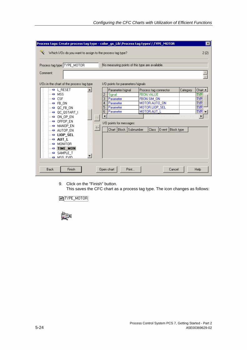
Configuring the CFC Charts with Utilization of Efficient Functions
Process Control System PCS 7, Getting Started - Part 2 5-24 A5E00369629-02
9. Click on the "Finish" button. This saves the CFC chart as a process tag type. The icon changes as follows:

Configuring the CFC Charts with Utilization of Efficient Functions
Process Control System PCS 7, Getting Started - Part 2 A5E00369629-02 5-25
5.4.2.3 Step 3 - How to Create the Import File "MOTOR_REAC1"
Ready to start? • The "color_gs_MP" project is open in the SIMATIC Manager.
• The plant view activated.
How to create an import file... 1. Select the folder "color_gs_MP/color_gs_Lib/Process Tag Types" in the tree.
2. Mark the process tag type "TYPE_MOTOR" in the detail window and select the menu command Options > Process Tags > Assign/Create Import File... This opens the Wizard "Process Tags – Assign/Create Import File", Step "Introduction".
3. Click the "Next" button. This starts the step "Which import file do you want to assign to the process tag type?".
4. Click in an input field of the "Column title" column and change the default name to match the entries in the following table. The column title will be later shown in the import file.
Column title Default name
Column title Adapted name
COUT.VALUE Output value COUT.VALUE FBON.VALUE Input value motor on FBON.VALUE FBON.SIM_ON Simulation motor FBON.SIM_ON MOTOR.AUTO_ON Auto mode on/off MOTOR.AUTO_ON MOTOR.LIOP_SEL Man/auto changeover MOTOR.LIOP_SEL MOTOR.AUT_L Selection man/auto MOTOR.AUT_L MOTOR.TIME_MON Monitoring time MOTOR.TIME_MON
5. Click on the "Create file template" button Since you have just generated the process tag type, you first have to create a new import file. The "Create File Template" dialog opens and the directory in which PCS 7 saves the import files by default is already open. PCS 7 suggests a file name for the import file, identical to the name of the process tag type.
6. Change the name to "MOTOR_REAC1.IEA" and click on the "OK" button. This opens the next dialog, "Create File Template", in which the "General" tab is active.

Configuring the CFC Charts with Utilization of Efficient Functions
Process Control System PCS 7, Getting Started - Part 2 5-26 A5E00369629-02
7. In the "Create File Template" dialog, make the settings listed in the following table and then click "OK".
Tab Activated check box
General Assigned AS (AS) Chart comment (ChComment) Block comment (BlockComment) Parameter Value (Value) I/O comment (ConComment) Textual interconnection (TextRef) Signals I/O comment Symbol name
8. Click the "Open file" button. The import file is opened in the Import-Export file editor and the first line is already filled out with default settings. Each line represents exactly one process tag.

Configuring the CFC Charts with Utilization of Efficient Functions
Process Control System PCS 7, Getting Started - Part 2 A5E00369629-02 5-27
5.4.2.4 Step 4 - Editing the Import File "MOTOR_REAC1"
The following describes the procedure for editing the import file in the IEA file editor. At the end of the section you will find a short description of the basic procedure for editing the data in Excel.
Ready to start? The import file "MOTOR_REAC1.IEA" is generated and open in the IEA file editor.
Follow the steps outlined below... 1. Fill out the first row – it represents the actual process tag NR311– to match the
entries in the following table:
Note
Due save space, the parameters in the following table are listed in columns and not lines – exactly opposite to the way they appear in the IEA file editor.
The order of the columns in the IEA file editor may be different from the order specified in the table. When entering the parameters, makes sure you have selected the correct column.
Column Sub-column Default entry Parameter
Project color_gs_Prj Apply Hierarchy Process tags\ Plant1\REAC1 AS S7 Program(1) Apply Chart ChName TYPE_MOTOR CFC_NR311 ChComment Output value COUT.VALUE
Symbol name --- NR311_con
ConComment Output value Apply BlockComment Digital output Apply Input value motor on FBON.VALUE
Symbol name --- NR3x1_on
ConComment Input value Apply BlockComment Digital input Apply Simulation motor FBON.SIM_ON
TextRef ActivateSimulation GENERAL\ACT_SIM.Q0
ConComment 1=Activate simulation
Apply
Auto mode on/off MOTOR.AUTO_ON
TextRef Level_Reac "-"CFC_LI311\TANK_LEV_MON.QL_WRN
ConComment AUTO Mode 1=ON 0=OFF
Apply
BlockComment MOTOR Apply Man/auto changeover MOTOR.LIOP_SEL
VALUE 0 1

Configuring the CFC Charts with Utilization of Efficient Functions
Process Control System PCS 7, Getting Started - Part 2 5-28 A5E00369629-02
Column Sub-column Default entry Parameter
ConComment Select: 1=Linking, 0=Operator Active
Apply
Selection man/auto MOTOR.AUT_L
VALUE 0 1
ConComment Linkable Input for MANUAL/AUTO Mode
Apply
Monitoring time MOTOR.TIME_MON
VALUE 3.0 10.0
ConComment Monitoring Time for ON [s]
Apply
Note
In the sub-column "TextRef" you will find the textual interconnection that you entered in the base chart as a text string. Here you replace the wildcard by the path reference to the "GENERAL" CFC chart which enables you to activate simulation in process mode.
You prefixed the textual interconnection for the "MOTOR.AUTO_ON" connection with the "-" character. This means that the input is negated.
2. Click on line number 4. This marks the line.
3. Select the menu command Edit > Duplicate Row... The "Duplicate Row" dialog opens.

Configuring the CFC Charts with Utilization of Efficient Functions
Process Control System PCS 7, Getting Started - Part 2 A5E00369629-02 5-29
4. Enter a "1" in the field "Number of duplicated rows" and click the "OK" button. This row is copied with all entries. Now you only have to enter the deviating parameters.
5. Enter the differing parameters as listed in the following table:
Note All deviating parameters are marked in bold in the table. Column Sub-column Parameter
Project color_gs_Prj Hierarchy Plant1\REAC1 AS Apply Chart ChName CFC_NP311 ChComment Output value COUT.VALUE Symbol name NP311_con ConComment Apply Input value motor on FBON.VALUE Symbol name NP3x1_on ConComment Apply BlockComment Simulation motor FBON.SIM_ON ConComment Apply TextRef GENERAL\ACT_SIM.Q0 Auto mode on/off MOTOR.AUTO_ON TextRef --- ConComment Apply BlockComment Man/auto changeover MOTOR.LIOP_SEL VALUE 0 ConComment Apply Selection man/auto MOTOR.AUT_L VALUE 0 ConComment Apply Monitoring time MOTOR.TIME_MON VALUE 10.0 ConComment Apply

Configuring the CFC Charts with Utilization of Efficient Functions
Process Control System PCS 7, Getting Started - Part 2 5-30 A5E00369629-02
Note A "---" string deletes a textual interconnection.
6. Select the menu command File > Save.
7. Close the IEA file editor. You return to the "Process Tags: Select/Create Import File" Wizard.
8. Click on the "Finish" button. This completes the work in the Wizard.
Note
If you are familiar with the spreadsheet program Excel, you can also edit the data of the import file there. The basic procedure is as follows:
1. Insert empty rows corresponding to the number of process tags in the IEA file editor.
2. Mark the area in the IEA file editor to be edited in Excel.
3. Insert the data using copy-and-paste.
4. Edit the data in Excel.
5. Mark the edited area in Excel and insert it back into the IEA file editor using copy-and-paste.
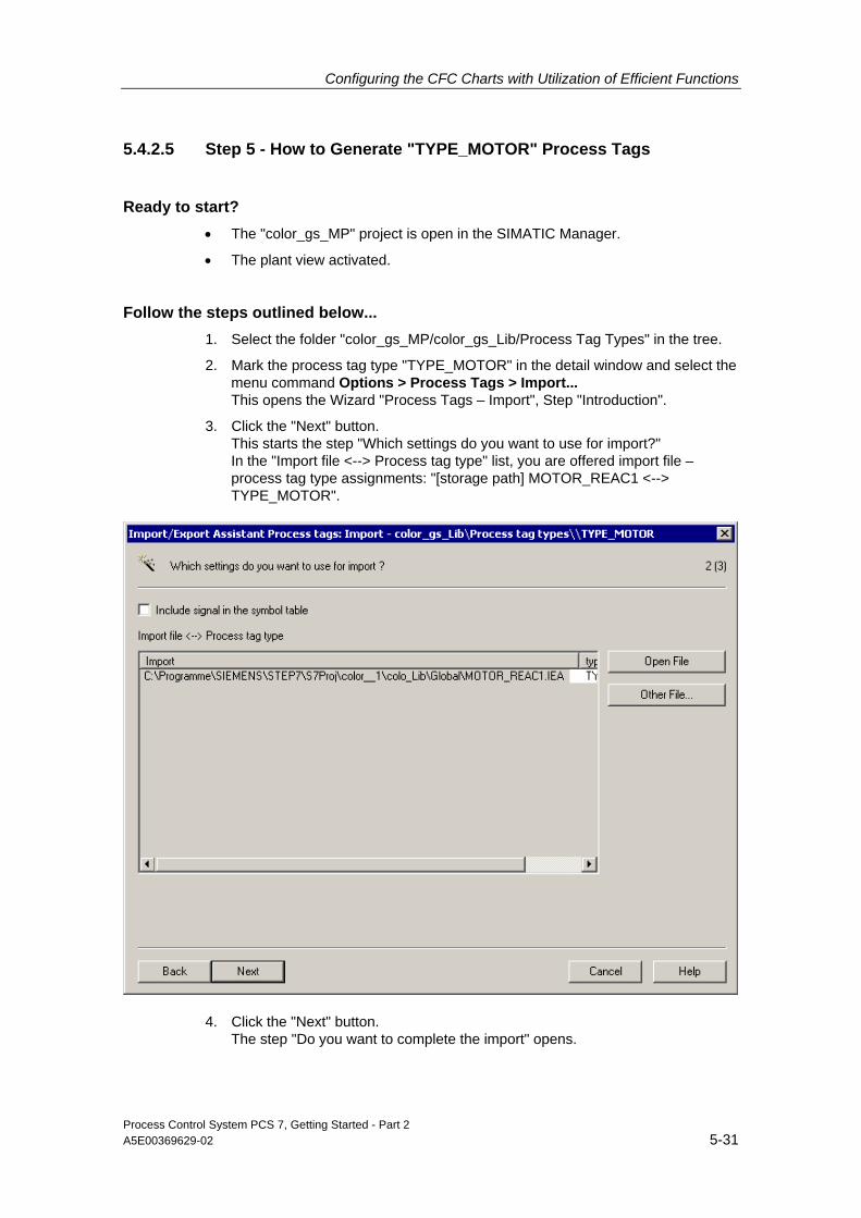
Configuring the CFC Charts with Utilization of Efficient Functions
Process Control System PCS 7, Getting Started - Part 2 A5E00369629-02 5-31
5.4.2.5 Step 5 - How to Generate "TYPE_MOTOR" Process Tags
Ready to start? • The "color_gs_MP" project is open in the SIMATIC Manager.
• The plant view activated.
Follow the steps outlined below... 1. Select the folder "color_gs_MP/color_gs_Lib/Process Tag Types" in the tree.
2. Mark the process tag type "TYPE_MOTOR" in the detail window and select the menu command Options > Process Tags > Import... This opens the Wizard "Process Tags – Import", Step "Introduction".
3. Click the "Next" button. This starts the step "Which settings do you want to use for import?" In the "Import file <--> Process tag type" list, you are offered import file – process tag type assignments: "[storage path] MOTOR_REAC1 <--> TYPE_MOTOR".
4. Click the "Next" button. The step "Do you want to complete the import" opens.

Configuring the CFC Charts with Utilization of Efficient Functions
Process Control System PCS 7, Getting Started - Part 2 5-32 A5E00369629-02
5. Click on the "Finish" button. The import begins and the progress bar is displayed. On the completion of the import, the process tags NR311 and NP311 are created and stored in the "REAC1" folder. The log of the import is displayed.
6. Click on the "Exit" button.

Configuring the CFC Charts with Utilization of Efficient Functions
Process Control System PCS 7, Getting Started - Part 2 A5E00369629-02 5-33
5.4.2.6 The Results...
Navigate to the following folder in the plant hierarchy: "color_gs_MP/color_gs_Prj/Plant1/REAC1".
There you will find two new CFC charts: "CFC_NP311" and "CFC_NR311" – these are the process tags that you have generated using the import process.
Open the newly generated "CFC_NR311" process tag in the CFC Editor. There you can see the results of the import and the relationship between the entries in the import file and the real process tag:
Block "FBON", input "SIM_ON" At the input "SIM_ON" in the "FBON" block you will find the textual interconnection – it has been converted into an actual interconnection: "Plant1\REAC1\\GENERAL(A1)\ACT_SIM.Q0"
By double-clicking on this interconnection at the border, you change switch directly to the corresponding interconnection partner.
These were the following parameters in the import file:
Column Sub Column
Default entry Parameter
Simulation motor FBON.SIM_ON
TextRef ActivateSimulation GENERAL\ACT_SIM.Q0
Block "FBON", input "VALUE" At the "VALUE" input in the "FBON" block you will find the interconnection to an I/O module.
These were the following parameters in the import file:
Column Sub Column
Default entry Parameter
Input value motor on FBON.VALUE
Symbol name "NR3x1_on" E0.2
Block "COUT", output "VALUE" Similarly, at the "VALUE" output in the "COUT" block you will find the interconnection to an I/O module.
These were the following parameters in the import file:
Column Sub Column
Default entry Parameter
Output value COUT.VALUE
Symbol name "NR311_con" A1.2 Corresponding block comment

Configuring the CFC Charts with Utilization of Efficient Functions
Process Control System PCS 7, Getting Started - Part 2 5-34 A5E00369629-02
Block "MOTOR", input "TIME_MON" At the "TIME_MON" input in the MOTOR" block you will find a concrete value. These were the following parameters in the import file:
Column Sub Column
Default entry Parameter
Monitoring time MOTOR.TIME_MON
VALUE 3.0 10.0
Block "MOTOR", input "AUTO_ON" At the "AUTO_ON" input in the "MOTOR" block you will find the textual interconnection that has been replaced by a concrete path reference: "Plant1\REAC1\\CFC_LI311 (A1)\TANK_LEV_MON.QL_WRN". This input has also been negated.
These were the following parameters in the import file:
Column Sub Column
Default entry
Parameter
Auto mode on/off MOTOR.AUTO_ON
TextRef Level_Reac "-"CFC_LI311\MEAS_MON.QL_WRN
5.4.3 How to Create "VALVE" Process Tags Using Process Tag Types
Five steps are involved in the creation of process tag types and generation of process tags from a process tag type for valve process tags:
Step What?
1 Creating the "TYPE_VALVE" base chart 2 Creating the "TYPE_VALVE" process tag type 3 Creating the "VALVE_REAC1" import file 4 Editing the "VALVE_REAC1" import file 5 Generating the "TYPE_VALVE" process tag

Configuring the CFC Charts with Utilization of Efficient Functions
Process Control System PCS 7, Getting Started - Part 2 A5E00369629-02 5-35
5.4.3.1 Step 1 - How to Create the "TYPE_VALVE" Base Chart
Follow the same basic procedure as for the "TYPE_MOTOR" process tag type. The following are brief instructions about the procedure with all of the required values in respective tables.
Ready to start? • The "color_gs_MP" project is open in the SIMATIC Manager.
• The plant view activated.
Follow the steps outlined below... 1. Insert the CFC chart "TYPE_VALVE" in the folder
"color_gs_MP/color_gs_Lib/Process Tag Types".
2. Open the "TYPE_VALVE" chart in the CFC Editor.
3. Open the library "color_gs_Lib\ S7 Program(1)\Blocks" or "color_gs_Lib/S7 Program(1)\Charts" in the catalog, insert the following objects using drag-and-drop and arrange them to correspond to the figure below.
- DRIVER/CH_DI - twice
- CONTROL/VALVE
- DRIVER/CH_DO
- SIMV
CH_DO
CH_DI
SIMV
VALVE
CH_DI
CH_DO

Configuring the CFC Charts with Utilization of Efficient Functions
Process Control System PCS 7, Getting Started - Part 2 5-36 A5E00369629-02
4. Enter the parameters as listed in the following table:
Block Name in project I/O Invisible
CH_DI1 FBOP CH_DI2 FBCL VALVE VALVE QCONTROL no CH_DO COUT SIMV –
5. Make the interconnections according to the following table:
Block Output Block Input
FBOP Q VALVE FB_OPEN FBCL Q VALVE FB_CLOSE VALVE QCONTROL COUT I QCONTROL SIMV CONTROL SIMV FBOPEN FBOP SIM_I FBCLOSE FBCL SIM_I
6. Insert the following textual interconnections as wildcards:
Block I/O Textual interconnection Meaning
FBOP SIM_ON ActivateSimulation Activates simulation in process mode
FBCL SIM_ON ActivateSimulation Activates simulation in process mode
VALVE L_RESET Reset Resets monitoring errors
7. Close the CFC Editor.

Configuring the CFC Charts with Utilization of Efficient Functions
Process Control System PCS 7, Getting Started - Part 2 A5E00369629-02 5-37
5.4.3.2 Step 2 - How to Create the "TYPE_VALVE" Process Tag Type
Follow the same basic procedure as for the "TYPE_MOTOR" process tag type. The following are brief instructions about the procedure with all of the required values in respective tables.
Ready to start? • The "color_gs_MP" project is open in the SIMATIC Manager.
• The plant view activated.
Follow the steps outlined below... 1. Mark the "TYPE_VALVE" CFC chart in the
"color_gs_MP/color_gs_Lib/Process tag types" folder and select the menu command Options > Process Tags > Create/Change Process Tag Type...
2. In the step "Which I/Os do you want to assign to the process tag type?" assign the following inputs/outputs to the process tag type:
Block I/O Meaning Parameter/
Signal
COUT VALUE Input value I/O module Signal FBCL VALUE Input value I/O module Signal SIM_ON Activates simulation Parameter FBOP VALUE Input value I/O module Signal SIM_ON Activates simulation Parameter VALVE L_RESET Resets the valves Parameter TIME_MON Monitoring time Parameter
3. Click on the "Finish" button. You have now competed creation of the process tag type.
Configuring the CFC Charts with Utilization of Efficient Functions
Process Control System PCS 7, Getting Started - Part 2 5-38 A5E00369629-02
5.4.3.3 Step 3 - How to Create the Import File "VALVE_REAC1"
Follow the same basic procedure as for the "TYPE_MOTOR" process tag type. The following are brief instructions about the procedure with all of the required values in respective tables.
Ready to start? • The "color_gs_MP" project is open in the SIMATIC Manager.
• The plant view activated.
Follow the steps outlined below... 1. Mark the "TYPE_VALVE" CFC chart in the
"color_gs_MP/color_gs_Lib/Process tag types" folder and select the menu command Options > Process Tags > Assign/Create Import File...
2. In the step "Which import file do you want to assign to the process tag type?", change the column titles as follows:
Column title Default name
Column title Adapted name
COUT.VALUE Output value COUT.VALUE FBCL.VALUE Input value for closing FBCL.VALUE FBCL.SIM_ON Activates simulation for closing FBCL.SIM_ON FBOP.VALUE input value for opening FBOP.VALUE FBOP.SIM_ON Activates simulation for opening FBOP.SIM_ON VALVE.L_RESET Reset valve VALVE.L_RESET VALVE.TIM_MON Monitoring time VALVE.TIME_MON
3. Click on the "Create file template..." button.
4. Name the import/export file "VALVE_REAC1.IEA".
5. In the "Create File Template" dialog, set the parameters to match the following table and click on "OK":
Tab Activated check box
General Assigned AS (AS) Chart comment (ChComment) Block comment (BlockComment) Block icon (BlockIcon) Parameter Value (Value) I/O comment (ConComment) Textual interconnection (TextRef) Signals I/O comment Symbol name
6. Click the "Open file" button.

Configuring the CFC Charts with Utilization of Efficient Functions
Process Control System PCS 7, Getting Started - Part 2 A5E00369629-02 5-39
5.4.3.4 Step 4 - Editing the Import File "VALVE_REAC1"
The following describes the procedure for editing the import file in the IEA file editor.
Ready to start? The import file "MOTOR_REAC1.IEA" is generated and open in the IEA file editor.
Follow the steps outlined below... 1. Fill out the first row – it represents the actual process tag – to match the entries
in the following table:
Column Sub
Column Default entry Parameter
Project color_gs_Prj Apply Hierarchy Process tags\ Plant1\REAC1 AS S7 Program(1) Apply Chart ChName TYPE_VALVE CFC_NK311 ChComment Output value COUT.VALUE Symbol name --- NK311_copen ConComment Output value Apply BlockComment Digital output Apply Input value for closing FBCL.VALUE
Symbol name --- NK31x_close
ConComment Input value Apply BlockComment Digital input Apply Activates simulation for closing FBCL.SIM_ON
TextRef ActivateSimulation GENERAL\ACT_SIM.Q0
ConComment 1=Activate simulation input value for opening FBOP.VALUE
Symbol name --- NK31x_open
ConComment Input value Apply BlockComment Digital input Apply Activates simulation for opening FBOP.SIM_ON
TextRef ActivateSimulation GENERAL\ACT_SIM.Q0
ConComment 1=Activate simulation Apply Reset valve VALVE.L_RESET TextRef Reset GENERAL\RESET_TON.Q ConComment Linkable Input RESET Apply BlockComment Single-Drive/Dual-
Feedback Valve Apply
BlockIcon 2 Monitoring time VALVE.TIME_MON
VALUE 3.0 10.0
ConComment Monitoring Time [s] Apply

Configuring the CFC Charts with Utilization of Efficient Functions
Process Control System PCS 7, Getting Started - Part 2 5-40 A5E00369629-02
Note Here you will find the new sub-column: "BlockIcon". The entries in this column enable you to control which block icon is generated. You are familiar with this function from Getting Started – Part 1 in which you controlled the representation of a valve as a block icon in the process object view. Now you can use the same function in the import file.
In this case, you are using another textual interconnection, the interconnection to VALVE.L_RESET which is also connected with the "GENERAL" CFC chart.
2. Select row 4 and duplicate it four times. This gives you a total of five process tags.
3. In the columns "Chart/ChName" and "Output value output module COUT.VALUE\SymbolName", set the parameters for the individual process tags as follows:
Row Column
"Chart/ChName" Column "output value COUT.VALUE\SymbolName"
5 CFC_NK312 NK312_copen 6 CFC_NK313 NK313_copen 7 CFC_NK314 NK314_copen 8 CFC_NK315 NK315_copen
Note
All other parameters remain unchanged. In a real project, you would have to change more parameters, for example, a unique symbolic name would have to be assigned to each interconnection to a I/O module. In this special case, you have interconnected several block I/Os to a single input/output of an I/O module to server as a simulation.
4. Save the file and close the IEA file editor.
5. Click on the "Finish" button.

Configuring the CFC Charts with Utilization of Efficient Functions
Process Control System PCS 7, Getting Started - Part 2 A5E00369629-02 5-41
5.4.3.5 Step 5 - Generating "TYPE_VALVE" Process Tags
You have now generated the "TYPE_VALVE" process tag type. You can use it now to generate a process tag for every valve contained in the project. Here in this Getting Started, you will first generate the process tags for the "REAC1" part of plant.
Ready to start? • The "color_gs_MP" project is open in the SIMATIC Manager.
• The plant view activated.
Follow the steps outlined below... 1. Mark the "TYPE_VALVE" CFC chart in the
"color_gs_MP/color_gs_Lib/Process tag types" folder and select the menu command Options > Process Tags > Import...
2. Pay special attention during the step "Which settings do you want to use for import?" that the correct import file – process tag type "[storage path] VALVE_REAC1 <--> TYPE_VALVE" is displayed in the list "Import file <--> Process tag type".
3. Perform the import. When you have completed the import process, the log file is displayed. This file is considerably more detailed than the one for generating the process tags for the motor. The following process tags are save in the PH folder "REAC1":
- CFC_NK311
- CFC_NK312
- CFC_NK313
- CFC_NK314
- CFC_NK315

Configuring the CFC Charts with Utilization of Efficient Functions
Process Control System PCS 7, Getting Started - Part 2 5-42 A5E00369629-02
4. Click on the "Exit" button.
5.4.3.6 How to Close Textual Interconnections...
You already worked with textual interconnections in the creation of process tags. If these interconnections are not yet closed, you can use a special PCS 7 function to close all of them now.
Ready to start? • The "color_gs_MP" project is open in the SIMATIC Manager.
• The "GENERAL" CFC chart is open in the CFC Editor. Check if the following interconnections are present:
- Block output "RESET_TON.Q" to all "VALVE.L_RESET" valve inputs
- Block output "ACT_SIM.Q0" to all valve and motor process tags for the "INPUT.SIM_ON" input.
If the interconnections are not closed, carry out the procedure described below.

Configuring the CFC Charts with Utilization of Efficient Functions
Process Control System PCS 7, Getting Started - Part 2 A5E00369629-02 5-43
Follow the steps outlined below... 1. Select the menu command Options > Make Textual Interconnections.
This closes all interconnections from output Q to all valve blocks and displays the following log file:
2. Double-click on any path at the border of the CFC chart. This takes you automatically to the CFC chart "CFC_NK31x", the interconnection flashes and is displayed in the color magenta. You will see here that the textual interconnection "RESET", which you specified in the process tag type, has been changed into a concrete interconnection.
3. Close the CFC Editor.

Configuring the CFC Charts with Utilization of Efficient Functions
Process Control System PCS 7, Getting Started - Part 2 5-44 A5E00369629-02
5.5 Modifying Process Tag Types
5.5.1 Making Changes at a Later Time
Process tag types are very convenient when you want to change your configuration at a later time. You make changes to a process tag type in the import file and then transfer the changed data to all generated process tags quickly by performing a new import.
The following changes may be necessary:
• Adding an addition parameter : For example, you would like to see different block icons on the OS see for the generated process tags and make this change using the import file.
• Deleting all generated process tags: This function is of interest when you have generated a great many process tags from a process tag type that you do not want to delete manually in the plant hierarchy.
• Adding an additional block I/O: For example, you need an additional block I/O that you want to configure using the import file.
In this Getting Started, you will add an additional parameter. We will provide an overview of the basic procedures for the other types of corrections.
5.5.2 The Most Important Information about the Import/Export File
You will work especially often with an import/export file when you make changes at a later point in time. To ensure you can work with confidence in this regard, take the time to familiarize yourself with the most important procedures described below. You may be familiar with many functions from working with spreadsheet programs.
Navigating in the table You can navigate in the table with the following keyboard commands:
• The UP and DOWN arrows moves you up and down rows in the columns
• The TAB key moves you to the right (forward) to the next cell and Shift + TAB moves you to the left (backward) to the preceding cell of a row
• The ENTER key exits a cell, for example, to conclude editing, and moves you to the next cell in the column

Configuring the CFC Charts with Utilization of Efficient Functions
Process Control System PCS 7, Getting Started - Part 2 A5E00369629-02 5-45
Selection in the table You can select cells in the table with the following keyboard commands:
• Selecting several cells: Press the Shift key and simultaneously press an arrow key
• Selecting an entire row: Click on the numbered cell at the beginning of the row
• Selecting several rows: Procedure as above and additionally press the Shift or CTRL key
• Selecting an entire column: Click on the column title cell
• Selecting several columns: Procedure as above and additionally press the Shift or CTRL key
Special considerations for the import/export file When making changes at a later time, note the following about editing the import file:
If you want to... ...then
Delete an existing textual interconnection or an interconnection to an I/O module
Enter the code word "---"
Leave an exiting interconnection unchanged Leave the input field empty
5.5.2.1 How to Add a Parameter
You will now add the "Block icon" parameter for the process tag type "TYPE_MOTOR" because you need this parameter for configuring the OS.
Ready to start? • The "color_gs_MP" project is open in the SIMATIC Manager.
• The plant view activated.
Follow the steps outlined below... 1. Mark the "TYPE_MOTOR" process tag type in the
"color_gs_MP/color_gs_Lib/Process tag types" folder and select the menu command Options > Process Tags > Assign/Create Import File....
2. Go to the step "Which import file do you want to assign to the process tag type?" and make sure that the correct import file, "…\MOTOR_REAC1.IEA", is displayed in the drop-down list.
3. Click the "Open file" button. The file opens in the IEA file editor.
4. Select the column "auto mode on/off MOTOR.AUTO_ON".
5. Select the menu command Edit > Expand column group.
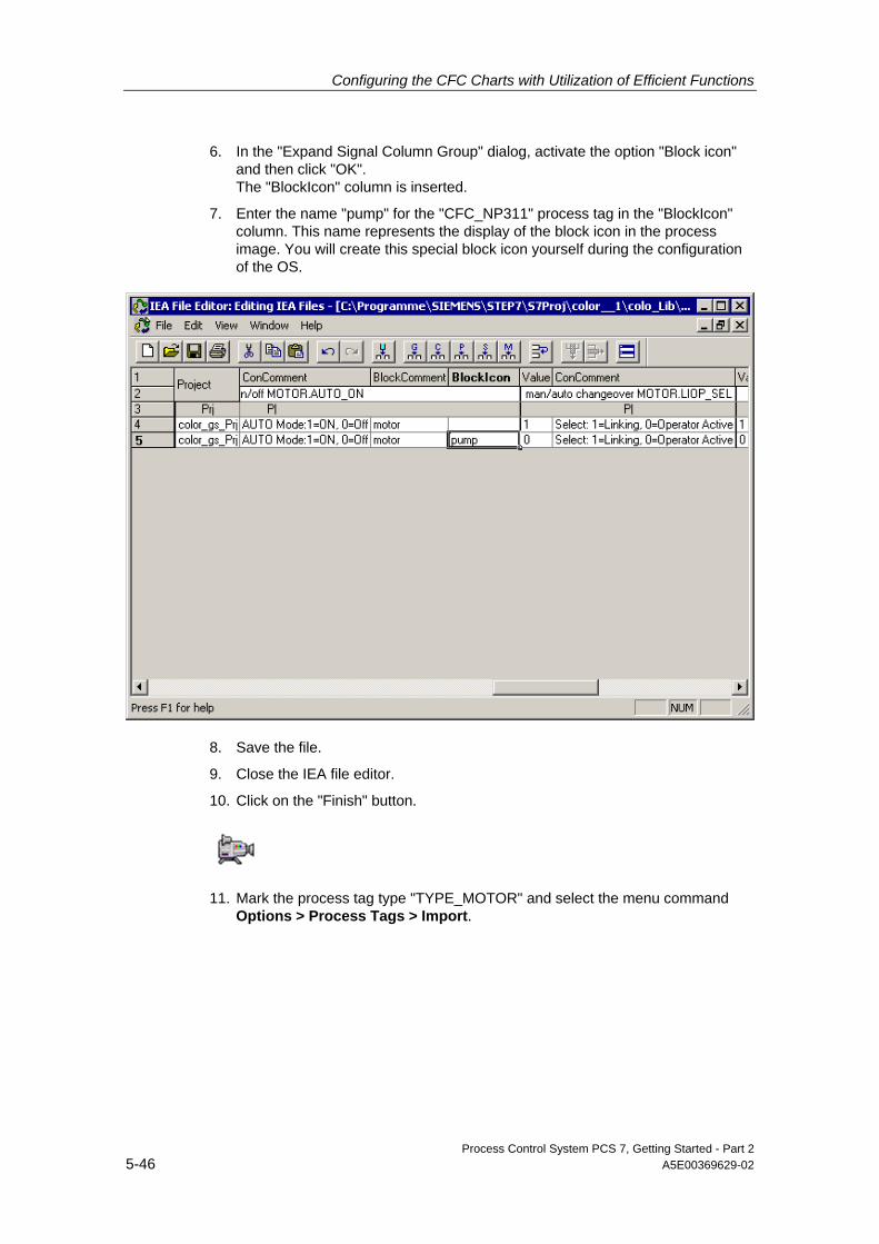
Configuring the CFC Charts with Utilization of Efficient Functions
Process Control System PCS 7, Getting Started - Part 2 5-46 A5E00369629-02
6. In the "Expand Signal Column Group" dialog, activate the option "Block icon" and then click "OK". The "BlockIcon" column is inserted.
7. Enter the name "pump" for the "CFC_NP311" process tag in the "BlockIcon" column. This name represents the display of the block icon in the process image. You will create this special block icon yourself during the configuration of the OS.
8. Save the file.
9. Close the IEA file editor.
10. Click on the "Finish" button.
11. Mark the process tag type "TYPE_MOTOR" and select the menu command Options > Process Tags > Import.

Configuring the CFC Charts with Utilization of Efficient Functions
Process Control System PCS 7, Getting Started - Part 2 A5E00369629-02 5-47
12. Check if the correct import file "MOTOR.REAC1.IEA" is selected and start the import. The existing process tags are modified to correspond to the parameters in the import/export file. You can see all of the modifications in the log.
In this case for the modification you have just made, "pump" has been entered in the input field "Block icon" of the block properties for the "MOTOR" block in the CFC chart "CFC_NP311". You can check it by opening the "CFC_NP311" CFC chart and viewing the block properties of the "MOTOR" block.

Configuring the CFC Charts with Utilization of Efficient Functions
Process Control System PCS 7, Getting Started - Part 2 5-48 A5E00369629-02
5.5.2.2 Making Additional Corrections - Basic Procedure
Caution
The following instruction are not part of the tasks dedicated to this Getting Started. The instructions are therefore kept to a minimum and are intended only as an overview of the basic principle involved. We have included these instructions to show you the wide variety of possibilities offered by process tag types.
The following basic options for making corrections are described:
• Delete all generated process tags
• Adding connection points
Deleting process tags 1. Make a copy of the original import file and name it "DELETE_[Name of the
original import file].IEA".
2. Open the file in the IEA file editor.
3. Mark the column "Project" and select the menu command Edit > Insert Column Group > General.
4. In the "Insert General Column Groups" dialog, activate the option "Import mode" and then click "OK". The "ImportMode" column is inserted as the first column.
5. For all process tags that you wish to delete, enter the command "DELETE" and save the file.
6. Close the IEA file editor.
7. Mark the process tag type "TYPE_MOTOR" and select the menu command Options > Process Tags > Import.
8. Open the import file that you have amended with the "DELETE" import mode and start the import. All process tags are deleted.

Configuring the CFC Charts with Utilization of Efficient Functions
Process Control System PCS 7, Getting Started - Part 2 A5E00369629-02 5-49
Adding block I/Os 1. Mark the process tag type and select the menu command Options > Process
Tags > Create/Change Process Tag Type...
2. Insert the additional connection and complete the change.
3. Open the corresponding import file and select the menu command Edit > Insert Column Group > Parameters or Signal. This insert the additional column.
4. Give the new column a descriptive name and save the import file.
5. Mark the process tag type and select the menu command Options > Process Tags > Assign/Create Import File... The inserted column from the import file is displayed in the "Undefined I/O points in import file:" list.
6. Drag this column onto the new connection point in the list "I/O points of the process tag type for parameters/signals:"
7. Complete the function.
8. Perform a new import.

Configuring the CFC Charts with Utilization of Efficient Functions
Process Control System PCS 7, Getting Started - Part 2 5-50 A5E00369629-02
5.6 Creating Additional CFC Charts
5.6.1 How to Create a "CFC_LI311" CFC Chart
This chart is used for fill level measurement and fill level simulation in REAC1.
Ready to start? • The "color_gs_MP" project is open in the SIMATIC Manager.
• The plant view activated.
Follow the steps outlined below... 1. Select the folder "color_gs_MP/color_gs_Prj/Plant1/REAC1" in the tree.
2. Insert the CFC chart "CFC_LI311" and open it in the CFC Editor.
3. Open the library "color_gs_Lib/ S7 Program(1)/Blocks" in the catalog and insert the following blocks using drag-and-drop and arrange them to correspond to the figure below.
- OPERATE/OP_A_LIM
- DRIVER/CH_AI - twice
- CONTROL/MEAS_MON
OP_A_LIM
CH_AI1 MEAS_MON
CH_AI2

Configuring the CFC Charts with Utilization of Efficient Functions
Process Control System PCS 7, Getting Started - Part 2 A5E00369629-02 5-51
4. Enter the parameters as listed in the following table:
Block Name in
project I/O Meaning Value
CH_AI1 TANK_LEV VH_RANGE Upper limit process value fill level
1200.0
MEAS_MON TANK_LEV_MON
U_AH Upper interrupt limit fill level 990.0
U_WH Upper warning limit fill level 950.0 U_AL Lower interrupt limit fill level 20 U_WL Lower warning limit fill level 40 MO_PVHR ** Upper display limit for faceplate
in the OS 1200
HYS Hysteresis 5 * CH_AI2 OUTFLOW VHRANGE Upper limit process value 0 VLRANGE Lower limit process value -100 SIM_V Simulation value for the flow
during draining -10
OP_A_LIM DRAIN_ MIN_LEV
U_HL Upper limit minimum fill level 1200.0
U_LL Lower limit minimum fill level 50 U ** Default minimum fill level 60
* default
** Connection must be visible
5. Open the library "color_gs_Lib/ S7 Program(1)\Charts" in the catalog and insert the "SIMREAC" chart under the "TANK_LEV_MON" block using drag-and-drop. This is the chart that you especially created for the fill level simulation.
6. Make the interconnections according to the following table:
Block Output Block Input
TANK_LEV V TANK_LEV_MON U SIMREAC LEVEL_OUTPUT TANK_LEV SIM_V OUTFLOW V SIMREAC AOUT

Configuring the CFC Charts with Utilization of Efficient Functions
Process Control System PCS 7, Getting Started - Part 2 5-52 A5E00369629-02
7. Make the following textual interconnections with a concrete path reference:
Block Input Textual interconnection Meaning
TANK_LEV SIM_ON GENERAL\ACT_SIM.Q0 Activates simulation SIMREAC BVALV_RMT1_1 CFC_NK113\VALVE.QOPENED Valve to REAC1 open BMOT_RMT1 CFC_NP111\MOTOR.QRUN Pump RMT1 running ARMT1 CFC_FC111\INPUT_U.V Simulation value for flow – this is
integrated into the fill quantity. BVALV_RMT2_1 CFC_NK117\VALVE.QOPENED Valve to REAC2 open BMOT_RMT2 CFC_NP112\MOTOR.QRUN Pump RMT2 running ARMT2 CFC_FC112\INPUT_U.V dto. – the values are read from the
RMT2 part of plant BOUT CFC_NP311\MOTOR.QRUN The drain pump must be running OUTFLOW SIM_ON GENERAL\ACT_SIM.Q0 Activates simulation
Note
The inputs BVALV_RMT1_2 and BVALV_RMT2_2 should not be interconnected to REAC1 part of plant.
Ensure that these inputs have the initial value "0".
All textual interconnections are automatically closed because all interconnection partners are available.
8. Mark the block I/Os to correspond to the following table and select the menu command Insert > Interconnection to Address. The selection list of the symbolic names for the block I/Os opens.
9. Double-click on the desired block I/Os. The global address is entered and the interconnections appear at the border.
Block Input/output Address
TANK_LEV Input "VALUE" LI311 OUTFLOW Input "VALUE" LI311_V
10. Close the CFC chart.

Configuring the CFC Charts with Utilization of Efficient Functions
Process Control System PCS 7, Getting Started - Part 2 A5E00369629-02 5-53
5.6.2 How to Create the "CFC Chart TC 311" CFC Chart
This chart regulated the temperature for REAC1.
Ready to start? • The "color_gs_MP" project is open in the SIMATIC Manager.
• The plant view activated.
Follow the steps outlined below... 1. Select the folder "color_gs_MP/color_gs_Prj/Plant1/REAC1" in the tree.
2. Insert the CFC chart "CFC_TC311" and open it in the CFC Editor.
3. Insert the blocks as listed in the following table in the specified order using drag-and-drop and arrange them to correspond to the figure below.
Note
The table provides information about the storage location and function of the blocks.
Block Location Tab Folder TOF Libraries "color_gs_Lib\ S7 Program(1)\ Blocks\IEC_TC" CTRL_PID Libraries "color_gs_Lib\ S7Program(1)\ Blocks\CONTROL" MUL_R Libraries "color_gs_Lib\ S7 Program(1)\ Blocks\MATH_FP" SEL_R Blocks "MULTIPLX" PT1_P Libraries "color_gs_Lib\ S7Program(1)\ Blocks\CONTROL" CH_AI Libraries "color_gs_Lib\ S7 Program(1)\ Blocks\DRIVER" CH_AO Libraries "color_gs_Lib\ S7 Program(1)\ Blocks\DRIVER"

Configuring the CFC Charts with Utilization of Efficient Functions
Process Control System PCS 7, Getting Started - Part 2 5-54 A5E00369629-02
CH_AO
CH_AI
TOF SEL_R
PT1_P
CTRL_PID
MUL_R
4. Enter the parameters as listed in the following table:
Block Name in
project I/O invisible Meaning Value
TOF TOF PT Maintains the temperature after the maximum value has been achieved
1m
CTRL_PID CTRL_TEMP SP_EXT External setpoint 80 GAIN Proportional coefficient 1 * TN Tracking time [s] 8 TV Derivative time [s] 0 * LIOP_INT_SEL Activates basic operator
control 0 *
LMN_HLM Upper interrupt limit 100 * LMN_LLM Lower interrupt limit 0 * SPEXTHLM Upper limit external
setpoint 100 *
SPEXTLLM Lower limit external setpoint
0 *
PVH_ALM Process value: upper interrupt limit
140
PVH_WRN Process value: upper warning limit
130
PVL_ALM Process value: lower interrupt limit
20

Configuring the CFC Charts with Utilization of Efficient Functions
Process Control System PCS 7, Getting Started - Part 2 A5E00369629-02 5-55
Block Name in project
I/O invisible Meaning Value
PVL_WRN Process value: lower warning limit
25
NM_PVHR Upper limit phys. measuring range process value
150
NM_PVLR Lower limit phys. measuring range process value
0 *
MO_PVHR Upper display limit 150 MO_PVLR Lower display limit 0 SEL_R SEL_R IN1 Minimum temperature of
the reactor 30
PT1_P PT1_P TM_LAG Time delay 60 CH_AI INPUT VHRANGE Upper limit process
value 150
MUL_R MUL_R IN2 Converts the valve setting in the temperature feedback
1 *
CH_AO OUTPUT UHRANGE Upper limit manipulated variable
100 *
* default
5. Make the interconnections according to the following table:
Block Output Block Input
TOF Q SEL_R K SEL_R OUT PT1_P U PT1_P V INPUT SIM_V INPUT V CTRL_TEMP PV_IN CTRL_TEMP LMN MUL_R IN1 CTRL_TEMP LMN CTRL_TEMP LMNR_IN CTRL_TEMP LMN OUTPUT U MUL_R OUT SEL_R IN0
6. Make the following textual interconnections:
Block Input Textual interconnection Meaning
INPUT SIM_ON GENERAL\ACT_SIM.Q0 Activates simulation TOF IN CFC_NK313\VALVE.QOPENED Valve 313 open.
All textual interconnections are automatically closed because all interconnection partners are available.

Configuring the CFC Charts with Utilization of Efficient Functions
Process Control System PCS 7, Getting Started - Part 2 5-56 A5E00369629-02
7. Mark the block I/Os to correspond to the following table and select the menu command Insert > Interconnection to Address and make the interconnections.
Block Input/output Address
INPUT Input "VALUE" TC311 OUTPUT Output "VALUE" TC311_c
8. Close the CFC chart and close the CFC Editor.

Configuring the CFC Charts with Utilization of Efficient Functions
Process Control System PCS 7, Getting Started - Part 2 A5E00369629-02 5-57
5.7 Summary
5.7.1 Summary of "Efficient Engineering in the CFC Configuration"
What have you learned in working with CFC charts?
In addition to using textual interconnections, you have learned two important function for efficient engineering:
• Chart-in-chart technique
• Process tag types
Both functions offer special advantages and are used for special requirements.
The following is a brief summary describing the most important properties of these two functions.
Chart-in-chart technique In the Getting Started tutorial, you used the chart-in-chart technique. In other words, you created general charts and used them numerous times in other charts. You inserted the simulation chart "SIMV" into all charts for valve process tags as hierarchical charts.
Note the following when using the chart-in-chart technique:
• Save the charts that you plan to use for the chart-in-chart technique in your master data library to ensure easy access and make them available to all project engineers in a distributed workgroup.
• Note that the chart-in-chart technique does not involve centralized editing. In other words, changes made in the hierarchical chart are not automatically transferred to all locations of use. If you insert the changed hierarchical chart into another base chart, you will have two different versions of the hierarchical chart in your project. When you open the base chart, of course, at first glance you will not know which version of the hierarchical chart you have used. Make sure you always change the name of the chart when you make subsequent changes to a hierarchical chart. Since the name is displayed when you use this chart in the base chart, you will immediately know which version of the hierarchical chart you are using.

Configuring the CFC Charts with Utilization of Efficient Functions
Process Control System PCS 7, Getting Started - Part 2 5-58 A5E00369629-02
Process tag types In this Getting Started tutorial, you have used process tag types to generate process tags of the same type. For example, you created the process tag type "VALVE" and then generated all five process tags required for the "REAC1" part of plant. Of course, you can also use this process tag type to generate other valve process tags in other parts of plant. You can also generate a large number of process tags using an import file.
Note the following when using process tag types:
• You can make changes in the generated process tags as required for the specific process tag. One exception: you cannot change the block I/Os that are configured by parameters in the import file.
• Assign column titles descriptive names.
• To maintain a clear relationship between the process tag types and the generated process tags, assign the corresponding import file a descriptive name.
• Before making substantial changes in the import file, you should make a backup copy of the original import file so you can revert to the "old version" if problems occur. This procedure is especially recommended when generating numerous process tags.
• You also have the option of editing the data in the import/export file externally in a spreadsheet program such as Excel. You should only use this option, however, if you are suitably familiar with the functions of the spreadsheet program. The IEA file editor offers comparable functions which should be sufficient to fulfill your needs during configuration.
Simultaneously generating process tags from several process tag types When generating process tags, you have the option of creating process tags from different process tag types in a single operation. The basic procedure is as follows:
1. In the plant view of the SIMATIC Manager, select the folder "color_gs\color_gs_lib\Process tag types".
2. Select the menu command Options > Process Tags > Import...
3. Step 2(3) the Import/Export Assistant, displays all import files you have already saved.
4. Delete the import files of all the process tag types from which you have not generated any process tags and complete the import.

Process Control System PCS 7, Getting Started - Part 2 A5E00369629-02 6-1
6 Configuring the CFC Charts with Utilization of Efficient Functions
6.1 Overview of the Work in SFC
During SFC configuration, you will perform the following tasks:
• Make corrections in the RMT part of plant– these corrections are needed to combine the operations of RMTx and REACx parts of plant.
• Work with SFC types – this function is a very important aspect for efficient engineering.
6.2 Modifing the SFC Charts in the 'RMT1/2' Parts of Plant
6.2.1 Modifications in the RMT Parts of Plant
You will need to modify the SFC charts from the RMT1 and RMT2 parts of plant using the interfaces between "RMTx" and "REACx" parts of plant. Valves NK311 and NK312 belong to the "REAC1" part of plant, valves NK321 and NK322 belong to "REAC2" part of plant. They, of course, must be open when liquid dosing begins. These valves are controlled by the SFC charts in RMT1 and RMT2.

Configuring the CFC Charts with Utilization of Efficient Functions
Process Control System PCS 7, Getting Started - Part 2 6-2 A5E00369629-02
6.2.1.1 How to Modify the SFC Charts of the RMTx Part of Plant
You already know how to work with the SFC Editor from Getting Started – Part 1. The new aspect here is the use of textual interconnections.
Ready to start? • The "color_gs_MP" project is open in the SIMATIC Manager.
• The plant view activated.
Follow the steps outlined below for the "RMT1" part of plant... 1. Select the "color_gs_MP/color_gs_Prj/Plant1/RMT1/FC111" folder in the tree
and open the "SFC_RMT1" chart in the detail window. The SFC editor is opened.
2. Select the step "START".
3. Select the menu command Edit > Object Properties. The "Properties" dialog opens.
4. Change to the "Initialization" tab.
5. Click on the button with the row number 11.
6. Open the context menu and select the menu command Insert Empty Line. A blank line is inserted on the button with number 11.
7. Place the cursor in the empty row 11 in the input field for the left address and click the "Browse" button. The "Browse" dialog box opens and the "Plant View" tab is active.
8. Mark the block in the tree: "Plant1\REAC1\CFC_NK311\VALVE". All the corresponding I/Os of the block are displayed in the right section.
9. Double-click on the "AUT_ON_OP" input. This brings you back to the "Properties" dialog and enters the value for the left address.
10. Set the right address to the value "Auto".
11. Click the "Apply" button. The value is entered.
12. Insert another empty row before row 12.
13. Enter the textual interconnection in this row:
- Left address: "CFC_NK321\VALVE.AUT_ON_OP" – this entry is displayed with a yellow background to show that it is a textual interconnection
- Right address: "1".
Caution
You must enter the value "1" for the textual interconnection – this is the Boolean valve for "Auto". Do not enter simply "Auto".

Configuring the CFC Charts with Utilization of Efficient Functions
Process Control System PCS 7, Getting Started - Part 2 A5E00369629-02 6-3
14. Click the "Apply" button.
15. Click on the arrow button to move to the next step and enter the information for the "RMT1" part of plant according to the table.
Note
Insert an empty row for the new statements after the existing statements for the valve controls so that the inputs/outputs are logically grouped together.
Step Comment Left address Right
address
Completed already: START
Direct interconnection Plant1\REAC1\CFC_NK311\VALVE.AUT_ON_OP Auto
Textual interconnection CFC_NK321\VALVE.AUT_ON_OP 1 INIT_LINE1 Direct interconnection Plant1\REAC1\CFC_NK311\VALVE.AUTO_OC TRUE INIT_LINE2 Textual interconnection CFC_NK321\VALVE.AUTO_OC 1 CLOSE_LINE Direct interconnection Plant1\REAC1\CFC_NK311\VALVE.AUTO_OC FALSE Textual interconnection CFC_NK321\VALVE.AUTO_OC 0 END Direct interconnection Plant1\REAC1\CFC_NK311\VALVE.AUTO_OC FALSE Textual interconnection CFC_NK321\VALVE.AUTO_OC 0

Configuring the CFC Charts with Utilization of Efficient Functions
Process Control System PCS 7, Getting Started - Part 2 6-4 A5E00369629-02
Follow the steps outlined below for the "RMT2" part of plant... 1. Open the "SFC_RMT2" chart.
2. Open the "Properties" dialog and enter the statements based on the table below:
Step Comment Left address Right
address
START Direct interconnection Plant1\REAC1\CFC_NK312\VALVE.AUT_ON_OP Auto Textual interconnection CFC_NK322\VALVE.AUT_ON_OP 1 INIT_LINE1 Direct interconnection Plant1\REAC1\CFC_NK312\VALVE.AUTO_OC TRUE INIT_LINE2 Textual interconnection CFC_NK322\VALVE.AUTO_OC 1 CLOSE_LINE Direct interconnection Plant1\REAC1\CFC_NK312\VALVE.AUTO_OC FALSE Textual interconnection CFC_NK322\VALVE.AUTO_OC 0 END Direct interconnection Plant1\REAC1\CFC_NK312\VALVE.AUTO_OC FALSE Textual interconnection CFC_NK322\VALVE.AUTO_OC 0
3. Close the "Properties" dialog and close the SFC Editor.

Configuring the CFC Charts with Utilization of Efficient Functions
Process Control System PCS 7, Getting Started - Part 2 A5E00369629-02 6-5
6.3 Working with SFC Types
6.3.1 Overview of SFC Types
This is your first theoretical overview of the SFC types. Of course, SFC types offer you a many more possibilities that cannot be described in detail in Getting Started – Part 2.
SFC types offer the great advantage of "reusability" because they are based on the type-instance concept. This means that you first create the SFC type and then generate an SFC instance with concrete process interfacing by inserting the SFC type into a CFC chart. This enables you to create SFC types for all sequences that occur more than once in a project, for example, heating, agitating, starting etc. The great advantage of the type-instance concept is centralized editing. For example, if you wish to add process values, setpoints etc. to the SFC type at a later point in time, they are added to all other SFC instances automatically.
Identifying characteristics of an SFC type The SFC type has certain properties that distinguishes it from an SFC chart:
• The SFC type has no runtime properties.
• The SFC type is managed in the component view and not in the plant hierarchy.
• The SFC type is managed and used as a function block and can therefore be found in the CFC block catalog under "Other blocks" and "All blocks". It is displayed as a block when inserted into a CFC chart.

Configuring the CFC Charts with Utilization of Efficient Functions
Process Control System PCS 7, Getting Started - Part 2 6-6 A5E00369629-02
6.3.2 What are the Important Elements in an SFC Type?
The following provides a brief overview of the elements in an SFC type that you will need for the configuration in Getting Started – Part 2:
• Control strategy Control strategies are used to configure an SFC type for industrial processes. You can define control strategies to use them in sequences, for example, heating, cooling, etc. The definition of control strategies is optional. However, when you want to run sequences according to a control strategy, the control strategies must be defined. The assignment of a control strategy to a sequence is made in the properties of the sequence. If you only want one sequence per control strategy, it is better to give the control strategies and the sequences similar names to help maintain an overview.
• Sequences You are already familiar with sequences from your work in Getting Started – Part 1. There you created the SFC chart with exactly one sequence for dosing the raw material. An SFC type can contain up to 32 different sequences. Each sequence is given a "start condition". The start condition "RUN = TRUE" means that the sequence is started when the SFC is activated. The start condition "QCS = 1" means that this sequence is started when the control strategy with the number "1" is activated.
• SFC Interface The SFC interface includes all inputs/outputs that were creating during the configuration of the SFC type and were made externally visible for the SFC instance in the CFC chart. There is a difference between the interface connections standardly generated for every SFC instance regardless of the definitions in the in the SFC type and the interface connections based on the definition of the characteristics in the SFC type.
• Characteristics Characteristics include, for example, control strategies, setpoints, process values, block contacts. You can define the exact characteristics needed, for example, the setpoint for a fill level. For every characteristic that you define, PCS 7 automatically generates the required inputs/outputs in the SFC instance. And you can make the concrete process interfacing for exactly these inputs/outputs.
Configuring the CFC Charts with Utilization of Efficient Functions
Process Control System PCS 7, Getting Started - Part 2 A5E00369629-02 6-7
6.3.3 Planning for the "REAC" SFC Type
Create an SFC type in the project "color_gs". This is to be used to control heating and drainage processes in the reactors. Beforehand, you must consider which elements you will need for your SFC type. You require the following elements for the "color_gs" project:
• Control strategies and sequences
• Setpoints
• Process values
• Block contacts
Defining the control strategies and sequences First define which reusable function units are available for the reactor. A control strategy and a separate sequence will be created for each of these function units. You require the following control strategies for the "color_gs" project:
• "Heat": This control strategy represents the heating process in the reactor.
• "Drain": The control strategy stands for emptying the reactor
In the "color_gs" project, each control strategy is assigned to exactly one sequence. This makes a total of three sequences:
• Reset (default name: Starting): This sequence is automatically started as soon as a sequence control system is started. It sets all valves of this part of plant to the "closed" state. This is needed to enable simulation to start in the process mode without problems.
Note
In actual practice, this sequence for closing the valves is usually executed at the end of the overall process. In this Getting Started, however, the sequence is executed at the beginning of the process to ensure reliable performance of the simulation.
• Heating: This sequence regulates the heating process using the controller block and opens/closes the corresponding intake valve.
• Drain: This sequence opens/closes the valves between reactor and filling tank and starts/stops the pump.
Defining the setpoints Now define the setpoints for the sequence control system. The plant operator can easily change these setpoints in process mode on the operator station. You can also define the limits. The setpoints, which can be specified by the plant operator, must be within these limits. Of course, the setpoints and their limits also apply to automatic mode – but we will not use this variant in this Getting Started tutorial.
For the "color_gs" project, the setpoint "Heating" is defined for the temperature in the heating process. It is used in the "Heating" sequence, i.e., the liquid in the reactor is heated until it reaches the setpoint.

Configuring the CFC Charts with Utilization of Efficient Functions
Process Control System PCS 7, Getting Started - Part 2 6-8 A5E00369629-02
Defining the process values Process values can be used for control within sequences. In the "color_gs" project, the process value "fill level" is used in the "Drain" sequence. The drainage pump must stop as soon as the minimum value for the reactor fill level is achieved.
Defining the block contacts Block contacts are custom defined for process tags, i.e., you need to create block contacts for the required process tags you wish to later connect through the SFC instance.
Note that the IN and OUT connections are reversed in the SFC instance for the block I/Os that are visible in the SFC interface of the SFC instance. For example, when you create a block contact for a "MOTOR" process tag , the "QRUN" connection at the "MOTOR" block is an OUT connection, in the SFC instance, however, it becomes an IN connection. This reversal is needed to make the required interconnections.
You require block contacts for the following process tag in your "color_gs" project:
• Control valve for the heating process
• Valve for the intake in the heating process
• Pump for drainage
• Valve for drainage

Configuring the CFC Charts with Utilization of Efficient Functions
Process Control System PCS 7, Getting Started - Part 2 A5E00369629-02 6-9
6.3.3.1 How to Create an SFC Type
The creation of the SFC chart requires 11 steps:
Step What?
1 Creating an SFC type in the SIMATIC Manager 2 Opening an SFC type in the SFC editor 3 Defining control strategies 4 Creating sequences 5 Specifying setpoints 6 Setting process values 7 Setting block contacts 8 Configuring the "RESET" sequence 9 Configuring the "Heating" and "Drain" sequences 10 How to Create an SFC instance 11 Saving in master data library
6.3.3.2 Step 1 - How to Create an SFC Type
Ready to start? • The "color_gs_MP" project is open in the SIMATIC Manager.
• The component view is activated.
Follow the steps outlined below... 1. Mark the object
"color_gs_MP/color_gs_Prj/SIMATIC 400(1)/CPU 417-4/S7 Program(1)/Charts" in the tree.
2. Select the menu command Insert > S7 Software > A SFC Type. The SFC type is inserted.
3. Enter the name "REAC".
Note
In contrast to usual procedure, SFC types for generation are not saved in the master data library. The SFC type is available as a block to be inserted as an SFC instance in the CFC chart only when it is saved in the above-mentioned folder. Upon completion, you will save the SFC type in the master data library in order to make it available for all the other engineers working in the multiproject, for example.

Configuring the CFC Charts with Utilization of Efficient Functions
Process Control System PCS 7, Getting Started - Part 2 6-10 A5E00369629-02
6.3.3.3 Step 2 - How to Open the SFC Type "REAC"
Ready to start? • The "color_gs_MP" project is open in the SIMATIC Manager.
• The component view is activated.
Follow the steps outlined below... 1. Select the folder
"color_gs_MP/color_gs_Prj/SIMATIC 400(1)/CPU 417-4/ S7 Program(1)/Charts".
2. Select the object "REAC" in the detail window.
3. Select the menu command Edit > Open Object. The SFC Editor opens and – exactly like an SFC chart – a sequence with the steps "START" and "END" as well as Transition 1 are already available.

Configuring the CFC Charts with Utilization of Efficient Functions
Process Control System PCS 7, Getting Started - Part 2 A5E00369629-02 6-11
6.3.3.4 Step 3 - How to Define the Control Strategies
Ready to start? • The "color_gs_MP" project is open in the SIMATIC Manager.
• SFC type "REAC" is open in the SFC Editor.
Follow the steps outlined below... 1. Select the menu command View > Characteristics.
The Characteristics Editor is open in the upper part of the SFC editor.
2. Mark the entry "Control strategies" in the tree. This displays an empty input line in the detail window.
3. Place the cursor in the input field of the "Name" column and enter the name "HEAT". This name is displayed to the plant operator in the process mode, for example, for the selection of a control strategy. The number "1" is assigned automatically by the system. This is the number that links the control strategy and sequence, for example.
4. Enter the text "Heating Reactor" the "Comment" column.

Configuring the CFC Charts with Utilization of Efficient Functions
Process Control System PCS 7, Getting Started - Part 2 6-12 A5E00369629-02
5. Make the following additional settings:
Name Number
automatically Comment
DRAIN 2 Drainage of Reactor
You have now defined all required control strategies.

Configuring the CFC Charts with Utilization of Efficient Functions
Process Control System PCS 7, Getting Started - Part 2 A5E00369629-02 6-13
6.3.3.5 Step 4 - How to Create the Sequences
The "RUN" sequence is automatically created with the SFC type. You need to rename this sequence and, of course, insert additional sequences.
Ready to start? • The "color_gs_MP" project is open in the SIMATIC Manager.
• SFC type "REAC" is open in the SFC Editor.
• The tab with the sequence "RUN" is activated.
Follow the steps outlined below... 1. Select the menu command Edit > Sequence Properties....
The "Properties" dialog box opens and the "General" tab is active.
2. Enter the name "Reset" in the "Name" field.
3. Click the "Apply" button.
4. Change to the "Start condition" tab.
5. Enter "STARTING" as start condition for Address 1.
6. Click in the input field for Address 2 and select "Starting" from the drop-down list.
7. Click on the "Apply" button and then on the "Close" button. The dialog is closed.
8. Select the menu command Insert> Sequence > At End . This inserts a new "SEQ1" sequence and displays it in a separate tab. This tab is automatically activated.

Configuring the CFC Charts with Utilization of Efficient Functions
Process Control System PCS 7, Getting Started - Part 2 6-14 A5E00369629-02
9. Select the menu command Edit > Sequence Properties and enter the following parameters:
Start condition Name Address 1 Operator Address 2 HEATING RUN = RUN QCS = 1
10. Click on the "Apply" button and then on the "Close" button.
11. Repeat steps 8 to 10 to define the "Drain" sequence:
Start condition Name Address 1 Operator Address 2 DRAIN RUN = RUN QCS = 2
12. Click on the "Apply" button and then on the "Close" button. This closes the "Properties" dialog.

Configuring the CFC Charts with Utilization of Efficient Functions
Process Control System PCS 7, Getting Started - Part 2 A5E00369629-02 6-15
6.3.3.6 Step 5 - How to Specify the Setpoints
You need to specify a setpoint for the heating temperature.
Ready to start? • The "color_gs_MP" project is open in the SIMATIC Manager.
• SFC type "REAC" is open in the SFC Editor.
• The Characteristics Editor is open.
Follow the steps outlined below... 1. Mark the entry "Setpoints" in the tree.
This displays an empty input line in the detail window.
2. Place the cursor in the input field of the "Name" column and enter the name "Heating".
3. Press the TAB key. A pull-down list is displayed in the input field of the "Data type" column and the name you have specified is automatically entered in the "I/O name" column. Change to a self-explanatory name after defining the data type.
4. Select the "REAL" data type from the drop-down list.
5. Make the following entries by placing the mouse pointer in the respective columns and entering the parameters based on the table below:
Column title Meaning Value
I/O name Self-explanatory I/O name for the setpoint value in the SFC interface
SPHeat
Initial value Setpoint which the control strategy uses until plant operator changes it
80
Low limit Minimum setpoint that the plant operator can specify in process mode
40
High limit Maximum setpoint that the plant operator can specify in process mode
150

Configuring the CFC Charts with Utilization of Efficient Functions
Process Control System PCS 7, Getting Started - Part 2 6-16 A5E00369629-02

Configuring the CFC Charts with Utilization of Efficient Functions
Process Control System PCS 7, Getting Started - Part 2 A5E00369629-02 6-17
6.3.3.7 Step 6 - How to Create Process Values
The process value will be set for the fill level.
Ready to start? • The "color_gs_MP" project is open in the SIMATIC Manager.
• SFC type "REAC" is open in the SFC Editor.
• The Characteristics Editor is open.
Follow the steps outlined below... 1. Mark the entry "Process values" in the overview.
This displays an empty input line in the detail window.
2. Place the cursor in the input field of the "Name" column and enter the name "Level".
3. Place the cursor in the "Data type" column. You are shown the available data types in a drop-down list.
4. Select the data type "REAL". This completes the parameter settings for the process value. The I/O name is automatically take from the "Name" field.
5. Create a new process value with the following parameters:
- Name: Level_min
- Data type: REAL
- I/O name: Levmin

Configuring the CFC Charts with Utilization of Efficient Functions
Process Control System PCS 7, Getting Started - Part 2 6-18 A5E00369629-02
6.3.3.8 Step 7 - How to Create the Block Contacts
Now create the block contacts. These inputs/outputs are generated in addition to the standard connections in the SFC instance.
Ready to start? • The "color_gs_MP" project is open in the SIMATIC Manager.
• SFC type "REAC" is open in the SFC Editor.
• The Characteristics Editor is open.
Follow the steps outlined below... 1. Mark the entry "Block contacts" in the tree.
This displays an empty input line in the detail window.
2. Place the cursor in the input field of the "Name" column and enter the name "HeatCtrl".
3. Press the TAB key. A pull-down list is displayed in the input field of the "Block" column and the name you have specified is automatically entered in the "I/O name" column.
4. Select the "CTRL_PID" block from the drop-down list. This pull-down list contains all blocks that you have used to date in your project. The chart inputs/outputs for the SFC instance are generated based on the selected block.
5. Position the mouse pointer in the "I/O name" column and overwrite the automatically entered name with the name "HCtrl". The name is short and descriptive but it contains the most important information about the name of the sequence and the corresponding process tag.
6. In the "comment" column, enter the supplementary information "Temperature control".
7. Make the following entries by placing the mouse pointer in the respective columns:
Name Block I/O name Comment
Completed already: HeatControl
CTRL_PID HCtrl Temperature control
HeatValve VALVE HValv Intake temperature control DrainValve1 VALVE DValv1 Valve1 drainage DrainValve2 VALVE DValv2 Valve2 drainage DrainMotor MOTOR DMot Pump drainage
Configuring the CFC Charts with Utilization of Efficient Functions
Process Control System PCS 7, Getting Started - Part 2 A5E00369629-02 6-19
8. Select the menu command View > Characteristics. This closes the Characteristics Editor since you have made all required entries.

Configuring the CFC Charts with Utilization of Efficient Functions
Process Control System PCS 7, Getting Started - Part 2 6-20 A5E00369629-02
6.3.3.9 Step 8 - How to Configure the "RESET" Sequence
Ready to start? • The "color_gs_MP" project is open in the SIMATIC Manager.
• SFC type "REAC" is open in the SFC Editor.
• The tab with the "RESET" sequence is activated.
Define steps 1. Select the menu command Insert > Step+Transition.
2. Insert a new Step 3 including Transition 2 below Transition 1. Now you have completed the sequence structure.
3. Select the menu command Insert > Select. The mouse pointer changes back to a selection cursor.
4. Select the step "START" and select the menu command Edit > Object Properties. The "Properties" dialog box opens and the "General" tab is active.
5. Change to the "Edit" tab and enter the following parameters based on the table below: Read the following note carefully:
Note
Since you are entering the parameters for an SFC type, you are working with the block contacts that you have defined in the Characteristics Editor. This means that you cannot navigate to the desired block connection using the "Browse" button and take them from there.
You can make the work considerably more easy by doing the following:
• Select the menu command View > Inputs/Outputs.
• Navigate to the desired connection in the overview.
• Drag and drop the connection name in the input line.
Remember that the "IN" and "OUT" I/Os are reversed for the SFC type.
I/O type Left address Right address
OUT HValv_LIOP_SEL TRUE OUT DValv1_LIOP_SEL TRUE OUT DValv2_LIOP_SEL TRUE OUT HValv_AUT_L TRUE OUT DValv1_AUT_L TRUE OUT DValv2_AUT_L TRUE

Configuring the CFC Charts with Utilization of Efficient Functions
Process Control System PCS 7, Getting Started - Part 2 A5E00369629-02 6-21
6. Click the "Apply" button.
7. Go to Step 3 using the arrow buttons.
8. Enter the name "CLOSE_VALVE" in the "General" tab and click the "Apply" button.
9. Enter the following parameters in the "Processing" tab:
I/O type Left address Right address
OUT HValv_AUTO_OC FALSE OUT DValv1_AUTO_OC FALSE OUT DValv2_AUTO_OC FALSE
10. Click on the "Apply" button and then on the "Close" button.

Configuring the CFC Charts with Utilization of Efficient Functions
Process Control System PCS 7, Getting Started - Part 2 6-22 A5E00369629-02
Defining transitions 1. Mark Transition "2" and select the menu command Edit > Object Properties.
The "Properties" dialog box opens and the "General" tab is active.
2. Enter the name "CLOSE_OK".
3. Click the "Apply" button.
4. Change to the "Condition" tab and enter the following parameters:
I/O type Left address Operator Right address
IN HValv_QCLOSED = TRUE IN DValv1_QCLOSED = TRUE IN DValv2_QCLOSED = TRUE
5. Click on the link button to OR the three operands. The "&" symbol is replaced by the ">1" symbol.
6. Click on the "Apply" button and then on the "Close" button. This saves your settings and the "Properties" dialog is closed.
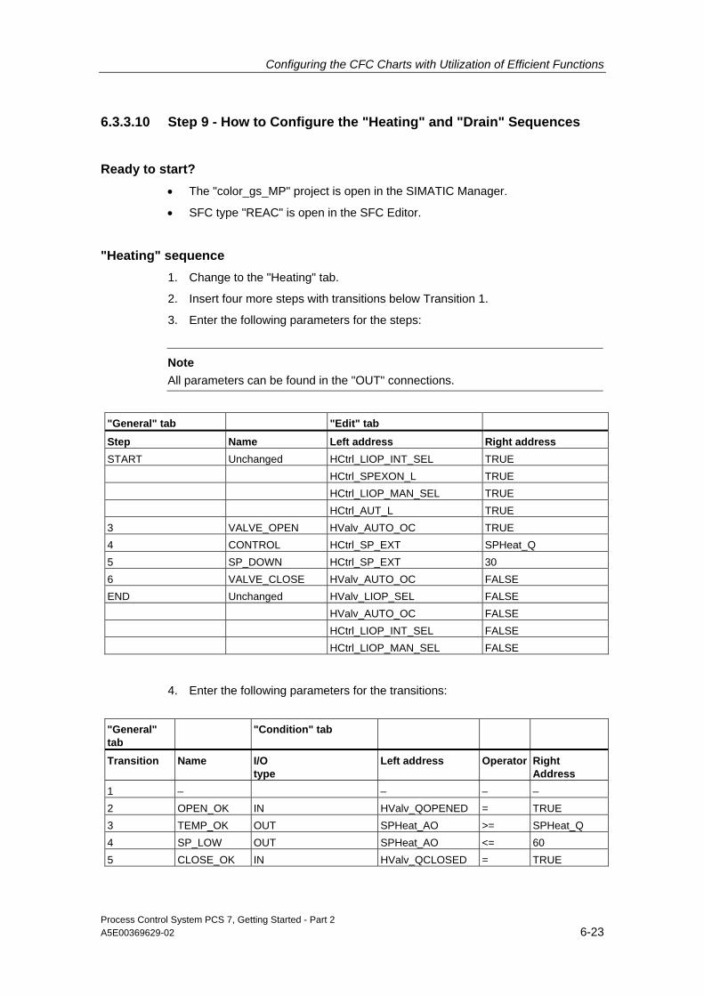
Configuring the CFC Charts with Utilization of Efficient Functions
Process Control System PCS 7, Getting Started - Part 2 A5E00369629-02 6-23
6.3.3.10 Step 9 - How to Configure the "Heating" and "Drain" Sequences
Ready to start? • The "color_gs_MP" project is open in the SIMATIC Manager.
• SFC type "REAC" is open in the SFC Editor.
"Heating" sequence 1. Change to the "Heating" tab.
2. Insert four more steps with transitions below Transition 1.
3. Enter the following parameters for the steps:
Note
All parameters can be found in the "OUT" connections.
"General" tab "Edit" tab Step Name Left address Right address START Unchanged HCtrl_LIOP_INT_SEL TRUE HCtrl_SPEXON_L TRUE HCtrl_LIOP_MAN_SEL TRUE HCtrl_AUT_L TRUE 3 VALVE_OPEN HValv_AUTO_OC TRUE 4 CONTROL HCtrl_SP_EXT SPHeat_Q 5 SP_DOWN HCtrl_SP_EXT 30 6 VALVE_CLOSE HValv_AUTO_OC FALSE END Unchanged HValv_LIOP_SEL FALSE HValv_AUTO_OC FALSE HCtrl_LIOP_INT_SEL FALSE HCtrl_LIOP_MAN_SEL FALSE
4. Enter the following parameters for the transitions:
"General" tab
"Condition" tab
Transition Name I/O type
Left address Operator Right Address
1 – – – – 2 OPEN_OK IN HValv_QOPENED = TRUE 3 TEMP_OK OUT SPHeat_AO >= SPHeat_Q 4 SP_LOW OUT SPHeat_AO <= 60 5 CLOSE_OK IN HValv_QCLOSED = TRUE

Configuring the CFC Charts with Utilization of Efficient Functions
Process Control System PCS 7, Getting Started - Part 2 6-24 A5E00369629-02
Sequence "Drain" 1. Change to the "Drain" tab.
2. Insert four more steps with transitions below Transition 1.
3. Enter the following parameters for the steps:
Note All parameters can be found in the "OUT" connections.
"General" tab "Edit" tab Step Name Left address Right address START Unchanged DMot_LIOP_SEL TRUE DMot_AUT_L TRUE 3 OPEN_VALVE DValv1_AUTO_OC TRUE DValv2_AUTO_OC TRUE 4 PUMP_ON DMot_AUTO_ON TRUE 5 PUMP_OFF DMot_AUTO_ON FALSE 6 CLOSE_VALVE DValv1_AUTO_OC FALSE DValv2_AUTO_OC FALSE END Unchanged DValv1_LIOP_SEL FALSE DValv1_AUTO_OC FALSE DValv2_LIOP_SEL FALSE DValv2_AUTO_OC FALSE DMot_LIOP_SEL FALSE DMot_AUTO_ON FALSE
4. Enter the following parameters for the transitions:
Note All parameters can be found in the "IN" connections.
"General" tab "Condition" tab Transition Name Left address Operator Right address 1 – – – – 2 OPEN_OK DValv1_QOPENED = TRUE DValv2_QOPENED = TRUE 3 ON_OK DMot_QRUN = TRUE Level < Levmin 4 OFF_OK DMot_QSTOP = TRUE 5 CLOSE_OK DValv1_QCLOSED = TRUE DValv2_QCLOSED = TRUE
5. Close the SFC Editor.

Configuring the CFC Charts with Utilization of Efficient Functions
Process Control System PCS 7, Getting Started - Part 2 A5E00369629-02 6-25
6.3.3.11 Step 10 - How to Create an SFC Instance
Ready to start? • The "color_gs_MP" project is open in the SIMATIC Manager.
• The following CFC charts open:
- CFC_TC311
- CFC_NP311
- CFC_NK313
- CFC_NK314
- CFC_NK315
- CFC_LI311
Follow the steps outlined below... 1. Select the folder "color_gs_MP/color_gs_Prj/Plant1/REAC1" in the tree.
2. Insert a CFC chart and name it "SFC_REAC".
3. Open the CFC chart.
4. Go to the "Block" tab in the catalog and open the folder "Other blocks".
5. Drag the "REAC" block into the CFC chart. This block is the SFC instance based on the SFC type that you have already created and configured. All of the inputs/outputs that you defined in the block contacts are contained here. You will also find the setpoints and process values that you have defined in the Characteristics Editor.
6. Select the menu command Edit > Object Properties. The "Properties" dialog opens.
7. Enter the name "REAC" in the "Name" field.
8. Click the "OK" button.
9. Now make the interconnections to the concrete blocks in the respective charts:
- Click on the output "HCtrl_SP_Ext" If the connection name is not fully visible, move the mouse slowly over the individual connections to have the full name of the connection displayed by the Tooltip function.
- Change to the "CFC_TC311" CFC chart.
- Click on the "CTRL_TEMP" block at the "SP_Ext" input. This automatically connects all inputs and outputs to the control block.
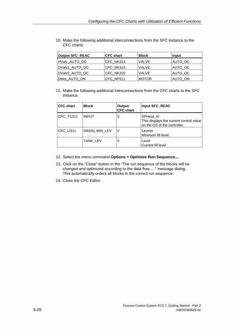
Configuring the CFC Charts with Utilization of Efficient Functions
Process Control System PCS 7, Getting Started - Part 2 6-26 A5E00369629-02
10. Make the following additional interconnections from the SFC instance to the CFC charts:
Output SFC_REAC CFC chart Block Input
HValv_AUTO_OC CFC_NK313 VALVE AUTO_OC DValv1_AUTO_OC CFC_NK314 VALVE AUTO_OC DValv2_AUTO_OC CFC_NK315 VALVE AUTO_OC DMot_AUTO_ON CFC_NP311 MOTOR AUTO_ON
11. Make the following additional interconnections from the CFC charts to the SFC instance:
CFC chart Block Output
CFC chart Input SFC_REAC
CFC_TC311 INPUT V SPHeat_AI This displays the current control value on the OS of the controller.
CFC_LI311 DRAIN_MIN_LEV V Levmin Minimum fill level
TANK_LEV V Level Current fill level
12. Select the menu command Options > Optimize Run Sequence...
13. Click on the "Close" button in the "The run sequence of the blocks will be changed and optimized according to the data flow....." message dialog. This automatically orders all blocks in the correct run sequence.
14. Close the CFC Editor.

Configuring the CFC Charts with Utilization of Efficient Functions
Process Control System PCS 7, Getting Started - Part 2 A5E00369629-02 6-27
6.3.3.12 Step 11 - How to Save the SFC Type in the Master Data Library
Ready to start? • The "color_gs_MP" project is open in the SIMATIC Manager.
• The component view is activated.
Follow the steps outlined below... 1. Mark the object "color_gs_MP/color_gs_Prj/SIMATIC 400(1)/CPU 417-4/
S7 Program(1)/Charts" in the tree.
2. Copy the SFC type "REAC".
3. Select the folder "color_gs_MP/color_gs_Lib/S7 Program(1)/Charts" in the tree.
4. Insert the SFC type.

Configuring the CFC Charts with Utilization of Efficient Functions
Process Control System PCS 7, Getting Started - Part 2 6-28 A5E00369629-02
6.4 Summary
6.4.1 Summary of "Efficient Engineering in the SFC Configuration"
What have you learned in working with SFC charts?
In addition to using textual interconnections in SFC charts, you have also learned about a very important function for efficient engineering: working with SFC types.
SFC types offer the special advantage of centralized editing. For example, whenever you add a new block contact for an SFC type, this block contact is automatically added to every SFC instance. Changes in the sequences are also automatically made in every SFC instance.
Caution
Make changes only to the SFC type that you have saved in the project folder in the component view and then save the most recent version in the master data library.

Process Control System PCS 7, Getting Started - Part 2 A5E00369629-02 7-1
7 Compiling, Downloading, Testing the Charts
7.1 Compiling, Downloading and Testing Your Project
You are familiar with this function from Getting Started – Part 1. Compiling and downloading is performed using the "Compile and Download Objects" command. The required settings are made in the respective dialog fields.
This part of Getting Started introduces testing of the SFC instance with your specific control strategies. It involves controlling the control strategies through a special connection of the SFC instance.
7.1.1 How to Compile and Download the Project
Ready to start? • The "color_gs_MP" project is open in the SIMATIC Manager.
• The plant view activated.
• The CPU is in the "STOP" mode – you need to perform a complete download at initialization; a complete download can only be made when the CPU is in STOP.
Follow the steps outlined below... 1. Select the "color_gs_MP\color_gs_Prj" folder in the tree structure.
2. Select the menu command PLC > Compile and Download Objects. The "Compile and Download Objects" dialog box opens.
3. Expand the entire tree so that all entries can be seen.
4. Make the settings according to the following table:
Object Compiling Downlo
ading
color_gs_Prj/[name of your local PC station]/Configuration X – color_gs_Prj/[name of your local PC station]/WinCC Application/OS(1)
– –
SIMATIC 400(1)/Hardware X X SIMATIC 400(1)/CPU 417-4/Charts X X

Compiling, Downloading, Testing the Charts
Process Control System PCS 7, Getting Started - Part 2 7-2 A5E00369629-02
5. Select the "Charts" object in the tree and click the "Edit..." button. The "Compile/Download Program to PLC" dialog opens.
6. Make the following settings:
Tab Option Activated
Compile charts as program Entire program yes Generate module drivers yes Update sampling time yes Delete empty runtime groups yes Make textual interconnections yes Download S7 Entire program yes

Compiling, Downloading, Testing the Charts
Process Control System PCS 7, Getting Started - Part 2 A5E00369629-02 7-3
7. Click the "OK" button.
8. Click on the "OK" button in the message "Remember that if you download later (e.g. in the SIMATIC Manager using...), the blocks will be deleted on the CPU.".
9. Click on the "Start" button.
10. Click on the "OK" button in the first message "Downloading program changes during operation can, in the case of malfunctions or program errors, cause serious damage to personnel and equipment!...".
11. Click on the "Yes" button in the dialog "If you want to download changes online, please make sure that the prerequisites have been met..... Do you want to continue?". The compiling and downloading processes are carried out. When these processes are completed the log file is displayed in the text editor: The compilation of the charts completed with warnings.
12. Close the text editor.

Compiling, Downloading, Testing the Charts
Process Control System PCS 7, Getting Started - Part 2 7-4 A5E00369629-02
13. Select the "Charts" object in the tree and click the "Single Object..." button in the "Display Log" area. The "Logs" dialog opens. The detailed warnings are shown in the here. These warnings are displayed because the textual interconnections could not be completed in the current state of the project. These interconnections can only be completed when the configuration of the REAC2 part of plant is finished. You can test this state of the project despite the warnings.
14. Click the "Close" button. This closes the "Logs" dialog.
15. Set the CPU back to RUN. Since you have configured external I/O in HW Config without closing the connections, the following error LEDs light on the CPU:
- EXTF – lights continuously
- BUS2F – flashes
Compiling, Downloading, Testing the Charts
Process Control System PCS 7, Getting Started - Part 2 A5E00369629-02 7-5
7.1.2 How to Test the Program
Since you want to test the configured control strategies on the ES but no graphic user interface is available for selecting the control strategy, you will need to connect the respective inputs.
Ready to start? • The "color_gs_MP" project is open in the SIMATIC Manager.
• The plant view activated.
Note
If you want to include the RMT1 and RMT2 parts of plant in the testing, make sure that every fill process is followed by a drain process.
Follow the steps outlined below... 1. Select the folder
"color_gs_MP\color_gs_Prj\Plant1\REAC1".
2. Open the "SFC_REAC" CFC chart in the CFC Editor.
3. Mark the SFC instance "REAC" – this is your SFC instance – and select the menu command Edit > Object Properties.
4. Switch the "CSP_OP" connection to visible and click "OK". The connection has the value "0" by default.
5. Select the menu command Debug > Test Mode. This brings you into test mode – you are already familiar with this command from Getting Started – Part 1.
6. Double-click on the "CSP_OP" input. The "Properties - Input/Output" dialog opens.
7. Enter the number of the desired control strategy in the "Properties - Input/Output" dialog and click "OK".

Compiling, Downloading, Testing the Charts
Process Control System PCS 7, Getting Started - Part 2 7-6 A5E00369629-02
CSP_OP Control strategy
1 HEATING 2 DRAIN
8. Mark the SFC instance "REAC" and select the menu command Edit > Open. The SFC instance is opened in the SFC Editor and the "RESET" tab is active.
9. Select the menu command Debug > Test Mode. This brings you into test mode.
10. Click on the "Start" button. The "RESET" sequence is now started. Immediately after this, the control strategy that you specified for the "CSP_OP" input in the CFC Editor is automatically started.
11. Enter another control strategy in the CFC chart and start the sequence again.
Note
To monitor the values at the inputs and outputs in the CFC charts , open the desired CFC charts in the CFC Editor and go into test mode there.
Carry out the following to make the values at the connections visible:
1. Press the key combination CTRL + A. This selects all blocks in the CFC chart.
2. Select the menu command Debug > Watch On. This displays all values at the connections.
3. If you want to monitor more I/Os, select the desired I/O and the menu command Debug > Input/Outputs > Add to Watch List.
12. Enter "0" again at the "CSP_OP" input.
Process Control System PCS 7, Getting Started - Part 2 A5E00369629-02 8-1
8 Configuring the PCS 7 OS
8.1 Overview of Work Involving the OS Configuration
You have already made many settings for the OS configuration in the SIMATIC Manager – you can conveniently use this data for the OS configuration. This includes the following functions, for example:
• You will conveniently interconnect the picture objects with the block I/Os from the CFC charts to create process pictures.
• You have already assigned block icons to the process tags in the CFC charts. This enables you to automatically generate the block icons.
• You defined the plant hierarchy in the SIMATIC Manager and made the settings for the OS area. This hierarchy is automatically represented on the OS in process mode.
Work involved in OS configuration The following work must be carried out for the OS configuration:
• Creation and use of custom symbols – you will create a new icon for the agitator in the reactor and for the drainage pump and use these functions for the graphic display. You are already familiar with the creation of process pictures from Getting Started – Part 1.
• Creation of a status display – you will combine the new icon for the agitator with the status display.
• Adaptation of the standard block icons – there are two motors in the "REAC1" parts of plant: one motor acts as an agitator, the other as a pump. These two functions should be easy to recognize by the plant operator due to the block icons. You will therefore modify the standard block icon for the motor.
• Creation of the process picture for the "REAC1" part of plant – you already have experience with this work from the creation of the process picture the "RMT1" and "RMT2" parts of plant.
• Adaptation of the process pictures or the "RMT1" and "RMT2" parts of plant– these corrections are required to enable the RMTx to be combined with REACx.

Configuring the PCS 7 OS
Process Control System PCS 7, Getting Started - Part 2 8-2 A5E00369629-02
8.2 Creating Graphic Symbols
8.2.1 Creation of Custom Symbols for Process Pictures
Custom process pictures may require special symbols, for example, for process tags. You will create these symbols once and then be able to use them multiple times.
In this Getting Started, you will create symbols for the following process tags:
• Agitator in the reactor
• Pump for drainage
All of the symbols that you create will be saved together in a separate file. Each individual icon will then be exported to a separate picture file with the format *.emf. You can then use the file to display a variety of states in a status display.
8.2.1.1 How to Open a Picture File for Your Symbols
You will save all of the symbols that you have created yourself in this file.
Ready to start? • The SIMATIC Manager is open.
• The component view is activated.
Follow the steps outlined below... 1. Select the folder
"color_gs_MP/color_gs_Prj/ [Name of the PC station] /WinCC Application/OS(1)".
2. Select the menu command Edit > Open Object. The WinCC Explorer opens.
3. In the navigation window, select the "Graphics Designer" object.
4. Open the context menu and select the menu command Open. An empty file opens in the Graphics Designer.
5. Select the menu command File > Save as... and save the file with the name "status_display.pdl" in the suggested directory.

Configuring the PCS 7 OS
Process Control System PCS 7, Getting Started - Part 2 A5E00369629-02 8-3
8.2.1.2 How to Create the Symbols for the Agitator
Ready to start? The "status_display.pdl" file is opened in the Graphics Designer.
Follow the steps outlined below... 1. If the object palette is not displayed, select the menu command
View > Toolbar and activate the "Objects" check box.
2. Create a rectangle.
3. Select the menu command View > Properties. The "Object Properties" dialog box opens.
4. Enter the following parameters – for all other parameters use the default values:
Property Attribute Parameter – "Static" column
Rectangle Object name Axis Rectangle/Geometry Width 5 Height 240 Rectangle/Colors Background color Black
5. Create a second rectangle with the following parameters
Property Attribute Parameter – "Static" column
Rectangle Object name Background Rectangle/Geometry Width 45 Height 15 Rectangle/Colors Background color Dark gray
6. Now create an agitator icon from several lines:
7. Position the icon on the small rectangle.

Configuring the PCS 7 OS
Process Control System PCS 7, Getting Started - Part 2 8-4 A5E00369629-02
8. Group all of the elements for the agitator icon.
9. Select all of the elements with the mouse and create a copy.
10. Assign the small rectangle the color "green".
11. Fill out the descriptive static text fields:
Type of agitator icon Text field / File name
Green agitator icon agitator_on.emf Gray agitator icon agitator_off.emf
12. Select all of the elements of the green rectangle – without the explanatory text fields – and select the menu command Edit > Group Object > Group.
Configuring the PCS 7 OS
Process Control System PCS 7, Getting Started - Part 2 A5E00369629-02 8-5
13. Now select all of the elements of the gray agitator – without the explanatory text fields – and select the menu command Edit > Group Object > Group.
14. Save the file "status_display.pdl".
15. Select the green agitator icon and select the menu command File > Export... The dialog "Save as Metafile" opens and the graphics folder for your project is automatically selected.
16. Enter the file name "agitator_on.emf" and click on the "Save" button.
17. Select the gray agitator and export the object to the file "agitator_off.emf".

Configuring the PCS 7 OS
Process Control System PCS 7, Getting Started - Part 2 8-6 A5E00369629-02
8.2.1.3 How to Create the Symbols for the Pump
The symbols for the pump are also saved to the "status_display.pdl" file. You do not need to create the symbols from scratch; you can modify an existing icon.
Ready to start? The "status_display.pdl" file is opened in the Graphics Designer.
Follow the steps outlined below... 1. Select the menu command Insert > Import.
The "Load Metafile" dialog opens.
2. Select the file "@motor_on.emf" and click on the "Open" button. The "Import – Document Size" dialog opens.
3. Accept the default settings and click the "OK" button. The icon for a motor – which you already know from Getting Started – Part 1 – is imported.
4. Delete the letter "M".
5. Select the "Polygon" object from the object palette and create a triangle roughly in the form of the pump icon as shown in the illustration below.
Note
Click on each corner and complete the polygon by double-clicking.
6. Enter the following parameters:
Property Attribute Parameter – "Static" column
Polygon Object name Pump Polygon/Geometry Width 25 Height 20 Polygon/Colors Background color Black

Configuring the PCS 7 OS
Process Control System PCS 7, Getting Started - Part 2 A5E00369629-02 8-7
7. If the triangle is not symmetric, grab the right corner with the mouse and pull it to the correct position.
8. Insert the triangle in the circle.
9. Select all of the elements with the mouse and create a copy.
10. Mark the circle and assign it the color "dark gray".
11. Create a third copy and assign it the color "red".
12. Group the individual elements for each icon without the explanatory text fields.
13. Fill out the descriptive text fields for each icon:
Symbol Text field / File name
Green circle pump_on.emf Dark gray circle pump_off.emf Red circle pump_error.emf
14. Save the file "status_display.pdl".
15. Export the new symbols and assign file names based on the entries in the corresponding text fields.
16. Close the file "status_display.pdl".

Configuring the PCS 7 OS
Process Control System PCS 7, Getting Started - Part 2 8-8 A5E00369629-02
8.3 Working with Standard Block Symbols
8.3.1 Where are the Standard Block Icons Saved?
The next step is to modify the existing standard block icons provided by PCS 7. The standard block icons are saved in a specific file – "@@PCS7Typicals.pdl" that is copied automatically during the PCS 7 installation. Your modified block icon is not saved in a new file rather than the original file. This file is given the name "@PCS7Typicals_gs2.pdl" in Getting Started – Part 2.
Do not confuse the block icon with the icons you have saved in the "status_display.pdl" file. The symbols that you have just created are pure graphic elements. Block icons already include many functions. For example, beginning with a block icon, you can open the corresponding faceplates in process mode and obtain a wide range of information about the process tag. Some block icons already have integrated group and status display. The most important aspect about standard block icons is the assignment to specific blocks in the CFC charts. This enables automatic generation of block icons.
The file names "@@PCS7Typicals.pdl" and "@PCS7Typicals _gs2.pdl" The "@@PCS7Typicals.pdl" file cannot be renamed. Based on the file name, PCS 7 automatically knows which file to use for the block icons when the function "Create/update block icons" is called. If only the "@@PCS7Typicals.pdl" file is available, PCS 7 automatically takes the block icons from this file.
Of you wish to modify block icons in your project, you can save them in the corresponding template files. You can use up to 10 different template files. When assigning a file name, ensure that the file name is based on the mandatory name component "@PCS7Typicals" and an additional variable name component. The mandatory name component is always at the beginning of the file name and is required for PCS 7 to be able to determine the files in which the additional block icons are saved. You can use any text you wish for the variable name component based on your project requirements.

Configuring the PCS 7 OS
Process Control System PCS 7, Getting Started - Part 2 A5E00369629-02 8-9
8.3.2 Modifying the Standard Block Icons
For Getting Started – Part 2, modify the following standard block icons:
• "MOTOR"
• "SFC type"
Block icon "MOTOR" You are already familiar with the "MOTOR" block icon from Getting Started – Part 1. The standard block icon represents the motor with an "M" within a circle. Since motors have a variety of functions in the "REAC" parts of plant, you should make these functions clearly recognizable to the plant operator at first glance. The agitator is – as already mentioned – represented by an "M" within a circle. There is no need to make any changes here since you are using the standard block icon. However, the pump requires another block icon. It should be displayed as a triangle within a circle. And this is exactly the block icon you will now create. You have already done some preliminary work in the "status_display.pdl" file in which you saved the symbols for the graphic representation.
Assigning block icons to blocks You may remember this from Getting Started – Part 1. There you entered specific numbers in the process object view to define the vertical or horizontal orientation of the "VALVE" block icon in the process picture. These numbers are also in the data for the block icon to enable assignment of the block icon to a block. You will make this assignment for the pump and agitator.
Block icon "SFC type" Using this block icon, you can call up the faceplate with which you can control the SFC instance in process mode, for example, to select control strategies or specify setpoints. Of course, a separate block icon must therefore be assigned to every SFC instance. Copies of the standard block icons "SFC type" are created for this purpose. Each copy is then assigned to a corresponding SFC instance.

Configuring the PCS 7 OS
Process Control System PCS 7, Getting Started - Part 2 8-10 A5E00369629-02
8.3.2.1 Creating a New Template File
Ready to start? The operator station OS(1) is open in the WinCC Explorer.
Follow the steps outlined below... 1. Select the object "OS(1)\Graphics Designer" in the tree.
2. Position the mouse pointer in the detail window.
3. Open the context menu and select the menu command New Picture. A new picture is added to the end of the list with the file name "NewPdl0.Pdl".
4. Select this new picture in the detail window.
5. Open the context menu and select the menu command Rename Picture.
6. Enter the name "@PCS7Typicals_gs2.pdl" in the "Name" field and click "OK". You have now renamed your new template file.
8.3.2.2 How to Modify the Standard Block Icons
Modification of the standard block icons requires four steps:
Step What?
1 Saving a copy of the required block icon 2 Changing the properties for the "MOTOR" block icon 3 Adapting the representation of the pump 4 Modifying the "SFC TYPE" block icon

Configuring the PCS 7 OS
Process Control System PCS 7, Getting Started - Part 2 A5E00369629-02 8-11
8.3.2.3 Step 1 - Saving a Copy of the Required Block Icon
Ready to start? • The operator station OS(1) is open in the WinCC Explorer.
Follow the steps outlined below... 1. Open the file "@PCS7Typicals_gs2.pdl".
This is the file in which you will save your custom block icons.
2. Open the file "@@PCS7Typicals.pdl" in the Graphics Designer. This is the file in which you will save the standard block icons.
3. Mark the "MOTOR" block icon including the title "MOTOR" in the "MOTOR" row of the file "@@PCS7Typicals.pdl" and select the menu command Edit > Copy.
4. Mark the "@PCS7Typicals_gs2.pdl" file in the detail window and select the context menu command Edit > Paste. This inserts a copy of the "MOTOR" block icon.
5. Position the block icon at the upper left of the drawing area.
6. Switch to the "@@PCS7Typicals.pdl" file and mark the block icon "SFC Type" in the "Other" row.
7. Select the menu command Edit > Copy.
8. Mark the "@PCS7Typicals_gs2.pdl" file in the detail window and select the context menu command Edit > Paste. This inserts a copy of the "SFC_Type" block icon.
9. Position the block icon "SFC_Type" below the "MOTOR" block icon.
10. Save the file "@PCS7Typicals_gs2.pdl".
11. Close the file "@@PCS7Typicals.pdl".
8.3.2.4 Step 2 - How to Change the Properties of the "MOTOR" Block Icon
Ready to start? The "@PCS7Typicals_gs2.pdl" file is opened in the Graphics Designer.
Follow the steps outlined below... 1. Change the title to "PUMP" just like in a normal text field.
2. Select the newly inserted block icon.
3. Select the menu command View > Properties.
4. Select the "General" property.
5. Double-click on the "Type" attribute. The "Text Input" dialog opens.

Configuring the PCS 7 OS
Process Control System PCS 7, Getting Started - Part 2 8-12 A5E00369629-02
6. Enter the name of the "Output value": "@MOTOR/pump".
Note
You already know the "Pump" value from your work in generating the motor process tags. You changed the existing process tags by adding an additional parameter, "BlockIcon". You entered exactly this value in the "BlockIcon" column in the import file.
7. Click on "OK" and then close the "Object Properties" dialog.
8. Save the file.
8.3.2.5 Step 3 - How to Adapt the Representation of the Pump
Ready to start? The "@PCS7Typicals_gs2.pdl" file is opened in the Graphics Designer.
Follow the steps outlined below... 1. Select the block icon with the title "PUMP".
2. Select the menu command Edit > Customized Object > Edit.... This separates the elements of the block icon that has been created as a "user object". It now consists of individual elements that you can separately edit.
Caution
In no case should you use the menu command "Ungroup" – this dissolves the user object and deletes the entire configuration of the block icon.
3. Select the circle with the "M". This graphic element is realized as a "status display (advanced).
4. Open the context menu and select the menu command Configuration dialog.... The dialog "Properties of the Extended Status Display" opens.
5. Go to the "Assign Pictures" tab.

Configuring the PCS 7 OS
Process Control System PCS 7, Getting Started - Part 2 A5E00369629-02 8-13
6. Mark the first line "Index 0". The assigned pictures are shown in the preview.
7. Check if the "*.wmf,*.emf" option is activated. This will display all pictures ending with the extensions "*.emf" and "*.wmf".
8. Double-click on the "pump_off.emf" file in the list of pictures. In the preview and the list you will see that the original motor representation in the base picture has been replaced by the representation of a pump.
9. Now double-click on the "pump_on.emf" file in the list of pictures. In the preview and the list you will see that the original motor representation in the flashing picture has been replaced by the representation of a pump.
10. Mark the next line "Index 1".
11. Replace all pictures in similar manner:
Row Base picture New
Base picture Flashing Picture New
Flashing Picture
Completed: Index 0
@motor_is_off.emf pump_off.emf @motor_is_on.emf pump_on.emf
Index 1 @motor_is_on.emf pump_on.emf – – Index 2 @motor_is_off.emf pump_off.emf – – Index 3 @MOTOR_Error.emf pump_error.emf – –
12. Click the "OK" button. You can see that the representation of the pump has already changed in the file "@PCS7Typicals_gs2".
13. While pressing the mouse button, draw a lasso around all elements of the block icon and select the menu command Edit > Customized Object > Finish Editing.
14. Save the file "@PCS7Typicals_gs2".
8.3.2.6 Step 4 - How to Modify the "SFC TYPE" Block Icon
Generating block icons for SFC instances
Note A block icon is automatically placed in the appropriate picture and interconnected when the "Generate/Update Block Icons" function is performed for all SFC instances that can be operated and monitored.
Ready to start? The "@PCS7Typicals_gs2 .pdl" file is opened in the Graphics Designer.
Configuring the PCS 7 OS
Process Control System PCS 7, Getting Started - Part 2 8-14 A5E00369629-02
Follow the steps outlined below... 1. Change the title of the block icon from "SFC_TYPE" to "SFC_TYPE_REAC".
2. Mark the faceplate icon and then select the menu command View> Properties. The "Object Properties" dialog box opens.
3. Select the property "Customized object".
4. Double-click on the "Object name" attribute and enter the name "REAC".
5. Select the "General" property.
6. Double-click on the "Tag" attribute. The "Text Input" dialog opens.
7. In the "Output value" field enter the complete path to the SFC instance including the name of the SFC instance in the CFC chart: "Plant1/REAC1/SFC_REAC/REAC".

Configuring the PCS 7 OS
Process Control System PCS 7, Getting Started - Part 2 A5E00369629-02 8-15
8. Make the following additional settings:
Property Attribute Value
general type @REAC/1 general tag name Plant1/REAC1/SFC_REAC/REAC
9. Close the "Object Properties" dialog box.
10. Save the file "@PCS7Typicals_gs2".
11. Close the Graphics Designer and close the WinCC Explorer.

Configuring the PCS 7 OS
Process Control System PCS 7, Getting Started - Part 2 8-16 A5E00369629-02
8.4 Generate Block Icons and Compile the OS In order to generate block icons, of course, you also need to work with the plant hierarchy – you are already familiar with this from Getting Started – Part 1. The steps involved are briefly outlined in the following. Follow the steps outlined below...
8.4.1 How to Activate the Option for Generating Block Icons
Ready to start? • The SIMATIC Manager is open. • The plant view activated. • The WinCC Explorer is closed.
Follow the steps outlined below... 1. Select the folder
"color_gs_MP/color_gs_Prj/Plant1/REAC1". 2. Select the "REAC1" process picture in the detail window and open the object
properties. 3. In the "Block Icons" tab activate the check box "Base block icons on the plant
hierarchy".
4. Click on "OK" and close the dialog.

Configuring the PCS 7 OS
Process Control System PCS 7, Getting Started - Part 2 A5E00369629-02 8-17
8.4.1.1 How to Generate the Block Icons
Ready to start? • The SIMATIC Manager is open.
• The plant view activated.
• The option for creating block icons is activated
Follow the steps outlined below... 1. Select the folder
"color_gs_MP/color_gs_Prj/Plant1/REAC1".
2. Select the menu command Options > Plant Hierarchy> Create/Update Block Icons.
3. Check the following:
- The correct picture is selected.
- The lower hierarchy levels included are set to "1".
4. Click the "OK" button. The block icons are generated.

Configuring the PCS 7 OS
Process Control System PCS 7, Getting Started - Part 2 8-18 A5E00369629-02
5. Click on the "Yes" button in the message dialog "To ensure possible automatic corrections to the WinCC picture interconnections,…. Do you want to see the function log now?. The log is opened in the text editor. There you will see the process tags for which the block icons were generated. You can also see all of the variants, for example, variant "2" of the "valve" process tag is the horizontal representation, the "pump" variant of the "motor" process tag represents the motor as a pump. This is the name you entered in the import/export file and will now be used in the generation of the block icons.
6. Close the text editor.
Note
If the log is not displayed, select the menu command Options > Plant Hierarchy > Open Block Icons Log.

Configuring the PCS 7 OS
Process Control System PCS 7, Getting Started - Part 2 A5E00369629-02 8-19
8.4.1.2 How to Compile the OS
Ready to start? • The SIMATIC Manager is open.
• The plant view activated.
• Block icons are generated.
Follow the steps outlined below... 1. Switch to the component view.
2. Select the "color_gs_MP\color_gs_Prj" folder in the tree structure.
3. Select the menu command PLC > Compile and Download Objects. The "Compile and Download Objects" dialog box opens.
4. Expand the entire tree so that all entries can be seen.
5. Activate the following check boxes:
- Object "OS(1)": Check box in the "Compile" column
- Object "Charts": Check box in the "Compile" column
6. Select the "OS(1)" object in the tree and click the "Edit..." button.

Configuring the PCS 7 OS
Process Control System PCS 7, Getting Started - Part 2 8-20 A5E00369629-02
7. Make the following settings in the "Settings: Compile OS" Wizard:
Step Settings
"Which areas do you want to assign to the operator station OS(1)?"
No additional settings are required here because OS(1) is already set to all areas by default and you will not use any other operator stations in your project.
"Select the network connections for the S7 programs associated with the areas"
Click on the "Connection" button and select the S7 connection you have made in NetPro from the "Select network connection" dialog box.
"Select the data you want to compile and the scope of the compilation":
Activate the following check boxes or option fields: • Tags and Messages • SFC Visualization • Picture Tree • Entire OS with memory reset
8. Click the "Apply" button.
9. Click on the "Start" button.
10. Click on the "Yes" button in the dialog "If you want to download changes online, please make sure that.....Do you want to continue?". The compilation process is started and the log file is displayed in the text editor when it is completed. Compiling of the charts ends with warnings because there are open textual interconnections in this version of the configuration that need to be closed.
11. Close the text editor.
12. Close the "Compile and Download Objects" dialog.

Configuring the PCS 7 OS
Process Control System PCS 7, Getting Started - Part 2 A5E00369629-02 8-21
8.5 Creating the Process Picture
You already know how to create a process picture from your work in Getting Started – Part 1. The steps involved in this work are briefly outlined in the following. Detailed instructions are provided for all tasks that were not covered in the first part of Getting Started. This includes the following tasks:
• Inserting and configuring a status display
• Inserting buttons
8.5.1 How to Create the Process Picture
Ready to start? • The operator station OS(1) is open in the WinCC Explorer.
Follow the steps outlined below... 1. Open the picture "REAC1" in the Graphics Designer.
All block icons have already been inserted here.
2. Select the menu command View > Library and insert the following additional objects from the various folders.
Path in the library Name of the object Number
Global Library/PlantElements/Pipes - Smart Objects/3D Pipe Horizontal
Pipe horizontal 8 x
Global Library/PlantElements/Pipes - Smart Objects/3D Pipe Vertical
Pipe vertical 3 x
Global Library/PlantElements/Pipes - Smart Objects/3D Pipe Elbow 1
Angle 1 x
Global Library/PlantElements/Pipes - Smart Objects/3D Pipe Elbow 2
Angle 2 x
Global Library/PlantElements/Pipes - Smart Objects/3D Pipe Elbow 3
Angle 1 x
Global Library/PlantElements//Tanks/Tank4 Reactor 1 x Global Library/Symbols/Valves/ 31 1 x

Configuring the PCS 7 OS
Process Control System PCS 7, Getting Started - Part 2 8-22 A5E00369629-02
3. Position the block icons and the new graphic objects as shown in the following illustration and change the size of the objects to roughly match:
4. Mark the reactor and then select the menu command View > Properties.
5. Enter the parameters based on the following table and then close the "Object Properties" dialog:
Property Attribute Parameter – "Static" column
Tank4 Object name Reactor 1 Tank4/Geometry Width 110 Height 300 Tank4/Colors Bar background color Dark gray Tank4/Tag assignment Maximum value 1200
Property Attribute Parameter – "Dynamic" column
Tank4/Tag assignment Fill level Tag connection via ES variables Plant1/REAC1/CFC_LI311/TANK_LEV_MON.U
Minimum value
Delete dynamic

Configuring the PCS 7 OS
Process Control System PCS 7, Getting Started - Part 2 A5E00369629-02 8-23
6. Create an icon for the heating using "line" and "polygon" objects.
7. Create a graphic representation for the block icons – use the standard graphic objects such as the rectangle and static text fields with the desired colors and position the block icons:
Block icon Representation
SFC type
Operator control block for simulation
Operator control block for minimum fill level
8. Save the file "REAC1.pdl".

Configuring the PCS 7 OS
Process Control System PCS 7, Getting Started - Part 2 8-24 A5E00369629-02
8.5.2 How to Insert a Status Display
Create a special status display for the agitator. The icon for the agitator represents the current status of the agitator exactly like the motor:
• Green: agitator active
• Gray: agitator inactive
Ready to start? • The operator station OS(1) is open in the WinCC Explorer.
• The process picture "REAC1" is open in the Graphics Designer.
• The object palette is open and the "Standard" tab is active.
Follow the steps outlined below... 1. Select the "Smart Objects/Status Display" object in the object palette.
2. Go to the drawing area. The mouse pointer changes to a small status display icon.
3. Draw a rectangle approximately the size of the agitator. The "Status Display Configuration" dialog opens.
4. Click on "Tag Selection". The tag selection dialog opens.
5. Make sure the "ES-Variables" check box in the "Data source" area is activated.

Configuring the PCS 7 OS
Process Control System PCS 7, Getting Started - Part 2 A5E00369629-02 8-25
6. Mark the entry "ES Tags/Plant1/REAC1/CFC_NR311/MOTOR" in the tree select the connection "QRUN" in the detail window.
7. Click the "OK" button. This enters the tag.
8. Now select the file "agitator_off.emf" in the "Selection of Picture" list and drag this picture into the "Basic picture" column.
9. Now click the "Add" button. This adds a new status to the list: Status "1".

Configuring the PCS 7 OS
Process Control System PCS 7, Getting Started - Part 2 8-26 A5E00369629-02
10. Now drag the picture "agitator_on.emf" from the picture selection to the base picture of status "1".
11. Click the "OK" button. The icon for the agitator is displayed in the process picture.
12. Now position the agitator in the reactor on the agitator motor and adapt the size.
13. Save the picture "REAC1".

Configuring the PCS 7 OS
Process Control System PCS 7, Getting Started - Part 2 A5E00369629-02 8-27
8.5.2.1 Inserting Buttons for RMT1 and RMT2
Ready to start? • The operator station OS(1) is open in the WinCC Explorer.
• The process picture "REAC1" is open in the Graphics Designer.
• The object palette is open and the "Standard" tab is active.
Follow the steps outlined below... 1. Select the "Windows Objects/Button" object in the object palette.
2. Go to the drawing area. The mouse pointer changes to a small button.
3. On the RMT1 feed pipe, – that is the NK311 inlet valve – draw a right angle of approximately the same size as the button. The "Button Configuration" dialog opens.
4. Enter the name "RMT1" in the "Text" field.
5. Click the "Font" button. The "Font" dialog opens.
6. Select "Arial" and click on "OK".

Configuring the PCS 7 OS
Process Control System PCS 7, Getting Started - Part 2 8-28 A5E00369629-02
7. Click on the button next to the input field "Change Picture on Mouse Click". The "Pictures" dialog opens.
8. Select the picture "RMT1.PDL" and click on "OK". The picture name is entered in the input field.
9. Click the "OK" button. The button is now configured.
10. Repeat steps 1 to 7 to insert buttons for changing the picture to the "RMT2" part of plant. Enter the parameters based on the following table:
Parameters Value
Position Feed pipe on the inlet valve "NK312" Button label RMT2 Link to picture RMT2.PDL

Configuring the PCS 7 OS
Process Control System PCS 7, Getting Started - Part 2 A5E00369629-02 8-29
Caution
Be aware that the rights of the plant operator to change the picture using the button are not checked in process mode. When you use this function in actual operation, the authorization must be ensured with a C script.
11. Save the picture "REAC1".

Configuring the PCS 7 OS
Process Control System PCS 7, Getting Started - Part 2 8-30 A5E00369629-02
8.5.3 How to Modify the Process Pictures RMT1 and RMT2
Since you are illustrating reactors 1 and 2 in the "REAC1" and "REAC2" process pictures, you do not need symbolic representation in the "RMT1" and "RMT2" pictures.
Ready to start? • The operator station OS(1) is open in the WinCC Explorer.
• The "RMT1" and "RMT2" process pictures are open in the Graphics Designer.
Follow the steps outlined below... 1. Change to the process picture "RMT1.pdl".
2. Delete Reactor 1 and its labeling.
3. Insert Windows object "Button" from the object palette.
4. Enter the parameters in the configuration dialog:
- "Text" field: enter "REAC1"
- "Font" button: select the "Arial" font
- "Change Picture on Mouse Click" button: select the "REAC1.pdl" picture
5. Delete Reactor 2 and its labeling.
6. Insert Windows object "Button" from the object palette.
7. Enter the parameters in the configuration dialog:
- "Text" field: enter "REAC2"
- "Font" button: select the "Arial" font
- "Change Picture on Mouse Click" field: manually enter "REAC2.pdl" as the picture name
Note
Since you have not yet configured the "REAC2" part of plant, you have to enter the picture name manually.
8. Mark the object "Raw Material Tank tank1" and open the "Object Properties" dialog using the context menu command, "Properties".
9. Select "Tag assignment" property and enter the value "1000" for the "Maximum value" attribute in the "Static" column.
10. Close the "Object Properties" dialog box.
11. Save and close the picture "RMT1.pdl".
12. Make the same changes for the process picture "RMT2.pdl".
13. Save and close the picture "RMT2.pdl".

Configuring the PCS 7 OS
Process Control System PCS 7, Getting Started - Part 2 A5E00369629-02 8-31
8.6 Summary
8.6.1 Summary of "Efficient Engineering in the OS Configuration"
What have you learned about configuring the OS?
• You have created custom symbols for your process pictures and can reuse them as needed. Of course, this does not offer centralized editing – compared to the chart-in-chart technique which you learned about in your work with CFC charts.
• You have learned how to create new block icons by modifying standard block icons. You have also become familiar with the relationship between blocks and the block icons. Block icons offer the special advantage of centralized editing. When you change a block icon in the "@PCS7Typicals" file and call the function "Create/update block icons" again, all block icons are updated accordingly.
Note
Be aware that an update of the block icons will overwrite any changes you have made in the process picture of the block icon.

Configuring the PCS 7 OS
Process Control System PCS 7, Getting Started - Part 2 8-32 A5E00369629-02

Process Control System PCS 7, Getting Started - Part 2 A5E00369629-02 9-1
9 How to Control and Monitor in the Process Mode
9.1 Functions in Process Mode
In Getting Started – Part 1 you became familiar with the operating and monitoring functions in process mode.
You will get to know two new functions in this part of Getting Started.
• Operating the SFC instance
• Switching the simulation method
You can also operate the "RMT1" and "RMT2" parts of plant as usual, of course.
Note
Be sure to execute a "DRAIN" to empty the reactor before every new dosing with RMTx.
9.2 Operating the SFC Instance
You can operate the SFC instance using the block icon with the corresponding faceplate. You generate the block icon using the automatic functions in PCS 7. Open the faceplate by clicking on the block icon.
You can perform the following operations here:
• Start an SFC instance
• Select a control strategy
• Specify the temperature setpoint
You can also switch the simulation method in process mode.

How to Control and Monitor in the Process Mode
Process Control System PCS 7, Getting Started - Part 2 9-2 A5E00369629-02
9.2.1 How to Start the SFC Instance
Ready to start? • The "color_gs" project is in process mode.
• Run the RMT1/RMT2 part of plant once through with dosing in Reactor 1.
Follow the steps outlined below... 1. Click on the block icon "...SFC-REAC/REAC".
The corresponding faceplate opens.
2. Select the entry "Prepared values" from the drop-down list. This activates the "Start" button.
3. Click on the "Start" button. The "SFC Control" dialog box opens.
4. Click the "OK" button. This starts the control strategy that is displayed in the drop-down list "Prepare control strategy".
5. Click on the "Section" button. This displays the sequence control with the tabs for the various sequences. You can carefully monitor which tasks and which transitions are being performed here. You will also see that the "RESET" sequence is always executed first at every start before the selected control strategy is started.
6. When the sequence is successfully completed, click on the "Reset" button. Then you can start the SFC instance again.

How to Control and Monitor in the Process Mode
Process Control System PCS 7, Getting Started - Part 2 A5E00369629-02 9-3
9.2.2 How to Select the Control Strategy
Ready to start? • The "color_gs" project is in process mode.
• The "SFC_REAC" faceplate opens.
Follow the steps outlined below... 1. Select the entry "Prepared values" from the drop-down list.
This activates the "Start" button and the "Prepare control strategy" drop-down list.
2. Select the entry "DRAIN" from the "Prepare control strategy" drop-down list. The "SFC Control" dialog box opens.
3. Click the "OK" button. The selected control strategy is displayed in the drop-down list.
4. Click on the "Start" button. The "SFC Control" dialog box opens.
5. Click the "OK" button. The sequence control is started.
6. When the sequence is successfully completed, click on the "Reset" button. Then you can start the SFC instance again.

How to Control and Monitor in the Process Mode
Process Control System PCS 7, Getting Started - Part 2 9-4 A5E00369629-02
9.2.3 How to Change the Setpoint for the Temperature
Ready to start? • The "color_gs" project is in process mode.
• The "SFC_REAC" faceplate opens.
Follow the steps outlined below... 1. Click on the block icon "...SFC-REAC/REAC".
The corresponding faceplate opens.
2. Select the entry "Prepared values" from the drop-down list. This activates the "Start" button and the "Prepare control strategy" drop-down list.
3. Select the control strategy "HEAT".
4. Click in the input field with the default setpoint – in this case the setpoint is "80". This is the value that you specified when you created the SFC type for the "Setpoints" property. This automatically shows the upper and lower limits of the setpoint. You have already specified these values in the properties of the SFC type.
5. Enter a setpoint within the specified limits and press ENTER. The "SFC Control" dialog box opens.
6. Click the "OK" button. This applies the specified setpoint.
7. Start the control strategy "HEAT" again and observe the values in the SFC and CFC charts.

How to Control and Monitor in the Process Mode
Process Control System PCS 7, Getting Started - Part 2 A5E00369629-02 9-5
9.2.4 How to Switch the Simulation Mode
You have two different options for simulation: simulation using CFC charts and simulation using I/O modules. Simulation with the CFC charts is set by default but can be easily changed in process mode.
Ready to start? • The "color_gs" project is in process mode.
• I/O modules are connected.
Follow the steps outlined below... 1. Click on the "..../ACT_SIM" block icon.
The faceplate opens.
2. Click on the "COMMAND" drop-down list.
3. Activate the "Off" option in the dialog and click on the "Execute" button.
4. Close the faceplate. This switches to simulation using the I/O modules. The circle in the block icon is now displayed as gray.
9.2.5 How to Specify the Minimum Fill Level
You inserted a faceplate in CFC chart CFC_LI311 in which you can specify the minimum fill level required by the drain process.
Ready to start? The "color_gs" project is in process mode.
Follow the steps outlined below... 1. Click on the "..../DRAIN_MIN_LEV" block icon.
The faceplate opens.
2. Enter the desired fill level.
3. Click the "Run" button.
4. Close the faceplate. This sets the minimum fill level and this exact fill level will be maintained in the reactor during the next drain.

How to Control and Monitor in the Process Mode
Process Control System PCS 7, Getting Started - Part 2 9-6 A5E00369629-02

Process Control System PCS 7, Getting Started - Part 2 A5E00369629-02 10-1
10 Executing the Additional Task
10.1 Configuring Reactor 2 at a Glance
In this sample project, the fastest way to configure the REAC2 part of plant is to copy the entire REAC1 plant section and then conveniently adjust the required parameters in the process object view.
PCS 7 of course offers other possibilities of multiplying parts of plant:
• You can quickly create new process tags from the created process tag types by editing the import/export file followed by an import procedure.
• You can use the created SFC type on all comparable parts of plant.
No extra work is required for the hardware configuration because both parts of plant are controlled from the same CPU. Besides, no additional Operator Stations are required because they have a single-node configuration. Also the symbolic names for the inputs and outputs are already assigned during the hardware configuration.
10.1.1 How to Configure the "REAC2" Part of Plant
Below is a description of the basic procedure when configuring the REAC2 plant section: Copy REAC1 part of plant and adjust the parameters.
Ready to start? • The sample project is open in the SIMATIC Manager.
• Process object view is activated
• "General" tab active
Follow the steps outlined below... 1. Select the hierarchy folder "REAC1" and copy it to the hierarchy folder
"Plant1". PCS 7 automatically assigns a new name "REAC1(1)".
2. Rename the new folder to "REAC2".

Executing the Additional Task
Process Control System PCS 7, Getting Started - Part 2 10-2 A5E00369629-02
3. In the "General" tab, in the "Name" column, change the name of the process tags according to the Process cell overview:
- Chart GENERAL(1) in GENERAL2
- Chart CFC_LI311(1) in CFC_LI321
- Chart SFC_REAC1(1) in SFC_REAC2
- Picture REAC1(1) in REAC2
- etc.
4. Navigate to the "Signals" tab and in the "Signal" column, adjust the symbolic names for the inputs and outputs of the distributed I/Os of Reactor 2. This means that the number "1" that stands for Reactor 1 must be replaced by the number "2", for example, "NK311_copen" changes to "NK321_copen", "TC311" changes to "TC321" etc. The associated comments and absolute address are automatically updated as soon as a signal name is changed.
Note
Make sure to leave the signals symbolic names which refer to Reactor 1 and Reactor 2 unchanged. In the sample project, they are the following names:
• NR3x1_on
• NP3x1_on
5. Open the CFC bchart CFC_LI321 and on chart "SIMREAC" add the following textual interconnections:
Block Input Textual interconnection
SIMREAC BVALV_RMT1_2 CFC_NK114\VALVE.QOPENED BMOT_RMT1 CFC_NP111\MOTOR.QRUN ARMT1 CFC_FC111\INPUT_U.V BVALV_RMT2_2 CFC_NK118\VALVE.QOPENED BMOT_RMT2 CFC_NP112\MOTOR.QRUN ARMT2 CFC_FC112\INPUT_U.V BOUT CFC_NP321\MOTOR.QRUN
Note
The inputs BVALV_RMT1_1 and BVALV_RMT2_1 should not be interconnected to REAC2 plant section.
The value for the inputs must be set to "0".
Note
Interconnections to charts stored outside the copied hierarchy folder will be deleted – all interconnections within the copied hierarchy folder are retained and are automatically updated after renaming the charts in the process object view.

Executing the Additional Task
Process Control System PCS 7, Getting Started - Part 2 A5E00369629-02 10-3
6. Select the menu command Options > Optimize Run Sequence...
7. Click on the "Close" button in the "The run sequence of the blocks will be changed and optimized according to the data flow....." message dialog. This automatically orders all blocks in the correct run sequence.
8. Close the CFC Editor.

Executing the Additional Task
Process Control System PCS 7, Getting Started - Part 2 10-4 A5E00369629-02
10.1.2 How to Compile the Changes
Ready to start? • The "color_gs_MP" project is open in the SIMATIC Manager.
• The plant view activated.
• CPU in "RUN_P" operating mode – You can download changes without the CPU having to be in "STOP"
• WinCC Explorer is closed
Follow the steps outlined below... 1. In the tree structure, select the "color_gs_MP\color_gs_Prj" folder and the
menu command PLC > Compile and Download Objects and the perform the settings according to the figure:
2. In the tree structure, select the object "color_gs_Prj/[name of your local PC station]/WinCC Application/OS(1)" and click on the "Edit" button.

Executing the Additional Task
Process Control System PCS 7, Getting Started - Part 2 A5E00369629-02 10-5
3. In the step "Select the data you want to compile and the scope of the compilation", activate the "Changes" option.
4. In the tree structure, select the "Charts" object and click on the "Edit..." button.

Executing the Additional Task
Process Control System PCS 7, Getting Started - Part 2 10-6 A5E00369629-02
5. In the "Compile Charts as Program" tab, activate the "Changes" and then click on the "Apply" button.

Executing the Additional Task
Process Control System PCS 7, Getting Started - Part 2 A5E00369629-02 10-7
6. Navigate to the "Download S7" tab, activate the "Changes" option and click on the "OK" button.
7. Click on the "Start" button to execute the compilation and download procedure. On the completion of the download procedure, the textual interconnections in the SFC charts are closed and all variable connections in the process pictures are updated for Reactor 2.

Executing the Additional Task
Process Control System PCS 7, Getting Started - Part 2 10-8 A5E00369629-02

Process Control System PCS 7, Getting Started - Part 2 A5E00369629-02 Index-1
Index
@ @@PCS7Typicals.pdl 8-8 @MOTOR/pump 8-11 @PCS7Typicals_gs2.pdl 8-11 @PCS7TypicalsJ_gs2.pdl 8-8
A ACT_SIM 5-6 ActivateSimulation 5-19 Adding connection points 5-48 Analog input module 2-3 Analog output module 2-3, 2-7
symbolic names 2-7 AS configuration 1-11
B Basic chart 5-3 Block contacts 6-7, 6-18
defining 6-18 Block icons 8-9, 8-11, 8-12, 8-13, 8-17,
8-18 adapting PUMP 8-12 assigning blocks 8-9 changing properties MOTOR 8-11 copying MOTOR 8-11 copying SFC type 8-11 generating 8-17 modifying the SFC type 8-13 MOTOR 8-9 SFC TYPE 8-9 tag 8-15 tag name 8-13 type 8-11 types 8-13
Blocks 5-1, 5-2 saving 5-2
BOUT 5-14 BUS2F 7-4 buttons 8-28
C CFC chart 5-5
inserting 5-5 CFC chart CFC_LI311 5-50
creating 5-50 CFC chart CFC_TC311 5-53
creating 5-53 Changes 5-44
process tag types 5-44 Characteristics 6-6 Chart-in-chart technique 5-3, 5-57 Cleaning 1-4 Compiling 7-3 Configuration Console 1-9 Connection partner 1-15 connection points 5-21 Connection points
parameters 5-21 signal 5-21
control strategy 6-11 defining 6-11
Control strategy 6-6 COUT 5-19, 5-35 Creating a file template 5-25 CSP_OP 7-5 CTRL_TEMP 5-53
D Default settings 1-8 Digital input module 2-3, 2-6
symbolic names 2-6 Digital output module 2-3, 2-6
symbolic names 2-6 Distributed I/O 2-1, 2-3 Download to PLC 7-1 Downloading 7-3
E Efficient engineering 5-57, 6-28, 8-31
CFC configuration 5-57 OS configuration 8-31 SFC configuration 6-28
Expand column group 5-45 EXTF 7-4

Index
Process Control System PCS 7, Getting Started - Part 2 Index-2 A5E00369629-02
F FB_CLOSED 5-9 FB_OPENED 5-9 FBCL 5-35 FBON 5-19 FBOP 5-35 Field bus 2-1, 2-3 Filling 1-4
G General CFC chart 5-4, 5-6
creating 5-6 generating block icons 8-16
H Hardware 1-1, 1-2
I/O modules 1-2 requirements 1-1
Hierarchical chart 5-3, 5-4 Holding phase 1-4 How to Select the Communication Module
in Simatic Shell 1-10
I I/O module 2-1 IM153-2 2-3 Import file 5-25, 5-26, 5-38
creating 5-25, 5-38 editing 5-25, 5-38
Import/Export Assistant 5-31 Import/export file 5-44
navigation 5-44 Selection 5-45
Import/export function 5-18 INPUT 5-52, 5-56
L Local editing 5-57
M MAC address 1-11 Master data library 5-1, 6-27
saving SFC type 6-27 MEAS_MON 5-50 MOTOR 5-19 MOTOR_REAC1.IEA 5-25
N NetPro 1-15
O Optimizing sequence 6-25 OS 1-13, 8-20
adapting name 1-13 compiling 8-20
OS configuration 1-14, 8-1 block icons 8-1 process picture 8-1 status display 8-1 symbols 8-1
OUTPUT 5-50, 5-56 overall project 1-4
P Parameters 5-21 PC station 1-12
renaming 1-12 Phases 1-5 Plant bus 2-1, 2-2 Plant hierarchy 3-1, 3-2, 3-3, 8-16
adapting names 3-1 expanding 3-2 hierarchy folder 3-2 process pictures 3-3
Plant structure 1-3 Process mode 9-1, 9-3, 9-4, 9-5
selecting control strategy 9-3 specifying setpoints 9-4 switching simulation method 9-5
Process picture 8-21, 8-24, 8-26, 8-27 creating 8-21 inserting buttons 8-27 status display 8-24
Process pictures 8-30 modifying RMT1/RMT2 8-30
Process tag type 5-45, 5-46 adding parameters 5-45
Process tag types 5-18, 5-19, 5-33, 5-44, 5-48, 5-58 changes made at a later time 5-48 make changes at a later time 5-44 procedure for creating 5-18 results 5-33
Process values 6-8, 6-17 setting 6-17
Production 1-5 PT1_P 5-53
Index
Process Control System PCS 7, Getting Started - Part 2 A5E00369629-02 Index-3
R Raw materials 1-4 Reset
valves 5-4 RESET_TON 5-6 RESET_TP 5-6 Resetting 5-4 Retrieval 1-10 RMT1 5-14, 5-15, 5-16 RMT2 5-14, 5-15, 5-16, 5-17
S Sample project 1-10
retrieving 1-10 Sample project color_gs 1-8
Settings 1-8 SEL_OPEN_CLOSE 5-9 SEL_R 5-53 SEL_RUN_STOP 5-12 Sequence 6-20
configuring RESET 6-20 sequences 6-13 Sequences 6-6, 6-23
configuring DRAIN 6-23 configuring HEATING 6-23 creating 6-13
Setpoints 6-7, 6-15 specifying 6-15
SFC charts 6-1 RMT1/RMT2 6-1 textual interconnections 6-1
SFC instance 6-25, 6-26, 9-1, 9-2 creating 6-25 operating 9-1 starting 9-2
SFC interface 6-6 SFC type 6-5, 6-6, 6-7, 6-9, 6-10, 6-11,
6-13, 6-15, 6-17, 6-18, 6-20, 6-23, 6-25 block contacts 6-8 characteristics 6-6 configuring HEATING
DRAIN sequences 6-23 configuring RESET sequence 6-20 control strategy 6-6 creating 6-9 creating sequences 6-13 creating SFC instance 6-25 defining block contacts 6-18 defining control strategy 6-11 opening 6-10 overview 6-5 process values 6-7 sequences 6-6 setpoints 6-7 setting process values 6-17
specifying setpoints 6-15 SFC types
identifiers 6-5 Signal 5-21 SIM_DELAY 5-9, 5-12 SIM_LEVEL 5-14 SIMMO 5-3, 5-12
creating 5-12 SIMREAC 5-3, 5-14
creating 5-14 Simulation 2-1, 5-3
CFC chart 5-3 Simulation chart 5-7, 5-12, 5-14
SIMMO 5-12 SIMREAC 5-14 SIMV 5-7
Simulation charts 5-3 Simulation method 5-4, 9-5
switching 9-5 Simulation methods
selecting 5-4 SIMV 5-3, 5-7, 5-8, 5-9, 5-10
chart I/Os 5-10 configure inputs/outputs 5-9 insert block 5-8
Software 1-2 Start condition 6-13 STARTING=TRUE 6-13 Status display 8-24
inserting 8-24 Symbolic names 2-6, 2-7, 2-9
analog output module 2-7 digital input module 2-6 digital output module 2-6 editing 2-8
Symbolic Names 2-5 Symbols 8-2, 8-3, 8-6, 8-7
agitator 8-3, 8-4, 8-5 creating 8-2 picture file 8-2 Pump 8-6
T Task definitions 1-7 TEMP 5-53 Template file 8-10 Testing 7-5
selecting control strategy 7-5 TextRef 5-25 Textual interconnections 5-42, 6-1
closing 5-42 SFC charts 6-1
TOF 5-53 Type 8-11
Index
Process Control System PCS 7, Getting Started - Part 2 Index-4 A5E00369629-02
TYPE_MOTOR 5-19, 5-21, 5-31, 5-37, 5-45 adding parameters 5-45 creating process tag type 5-21, 5-37 creating the base chart 5-19 generating process tags 5-31
TYPE_VALVE 5-35, 5-38, 5-41 creating import file 5-38 creating the base chart 5-35 generate process tags 5-41
V VALVE 5-35 Valves 5-4
resetting 5-4