process control system pcs 7 library of driver blocks for ... · pdf filegraph higraph cfc c...
TRANSCRIPT

Preface, Contents
Installation 1
Block Concept 2
Driver Blocks 3
Communication 4
Annex
Technical Data A
Abbreviations B
Applicable Documents C
Glossary
01/2007C79000-G8076-C711-04
Process Control System PCS 7Library of Driver Blocks for TELEPERM I/O Peripherals
Reference Manual
SIMATIC

This manual contains notices which you should observe to ensure your own personalsafety, as well to protect the product and connected equipment. These notices are mar-ked as follows to the level of danger. The notices to ensure your personal safety areadditional highlighted in the manual by a warning triangle.
!Danger
indicates an imminently hazardous situation which, if not avoided, will result in deathor serious injury.
!Warning
indicates a potentially hazardous situation which, if not avoided, could result in deathor serious injury.
!Caution
used with the safety alert symbol indicates a potentially hazardous situation which, ifnot avoided, may result in minor or moderate injury.
Caution
used without safety alert symbol indicates a potentially hazardous situation which, ifnot avoided, may result in property damage.
Notice
Notice used without the safety alert symbol indicates a potential situation which, if notavoided, may result in an undesireable result or state.
The device/system may only be set up and operated in conjunction with this manual.Only qualified personnal should be allowed to install and work on this equipment. Qua-lified persons are defined as persons who are authorized to commission, to ground,and to tag circuits, equipment, and systems in accordance with established safetypractices and standards.
Please note the following:
!
Warnings
This device and its components may only be used for the applications described in thecatalog or technical description, and only in connection with devices or componentsfrom other manufactorers which have been approved or recommended by Siemens.
This product can only function correctly and safely if it is transported, stored, set up,and installed correctly, and operated and maintained as recommended.
TELEPERM�, SIMATIC� and SIMATIC NET� are registered trademarks of SiemensAG. Third parties using for their own purposes any other names in this document whichrefer to trademarks might infringe upon the rights of the trademark owners.
We have checked the contents of this manual for agreement with thehardware and software described. Since deviations cannot be pre-cluded entirely, we cannot guaranteefull agreement. However, thedata in the manual are reviewed regularly and any necessary correc-tions included in subsequent editions. Suggestions for improvementare welcomed.
Exclusion of liabilityCopyright � Siemens AG 2001 - 2007 All rights reserved
The reproduction, transmission or use of this document or itscontents is not permitted without express written authority. Offenders will be liable for damages. All rights, including rightscreated by patent grant or registration of a utility model or design, arereserved.
� Siemens AG 2001 - 2007Technical data subject to change.
Siemens Aktiengesellschaft Order No. C79000-G8076-C711
Siemens AGAutomation and Drives GroupSystems Engineering DivisionD-76181 Karlsruhe
Safety Guidelines
Qualified Staff
Intended Use
Trademarks

iiiLibrary of Driver BlocksC79000-G8076-C711-04
Preface
The driver block library offers a selection of programs (blocks) ready to usefor common automation tasks.They provide you with a basis for carrying out such tasks as:
� Measured–value and digital–value acquisition (with monitoring of thevalidity and message output, if appropriate)
� Analog–value processing
� Output of results via analog or digital output modules
This manual describes the components of this library. It explains the blockconcept in accordance with which the blocks are structured and applicable.The individual block description provides you with the necessary informationto program, set up and maintain the automation software created with it. Theinformation encompasses the brief description of the function (for rapid in-formation), the method of operation and the interface description.
This manual is intended for persons working in the fields of project planning,setting up and service.
This manual is valid for the “Driver blocks library” software, version 1.0.1.
Description of theManual
Readers
Validity of theManual
ivLibrary of Driver Blocks
C79000-G8076-C711-04
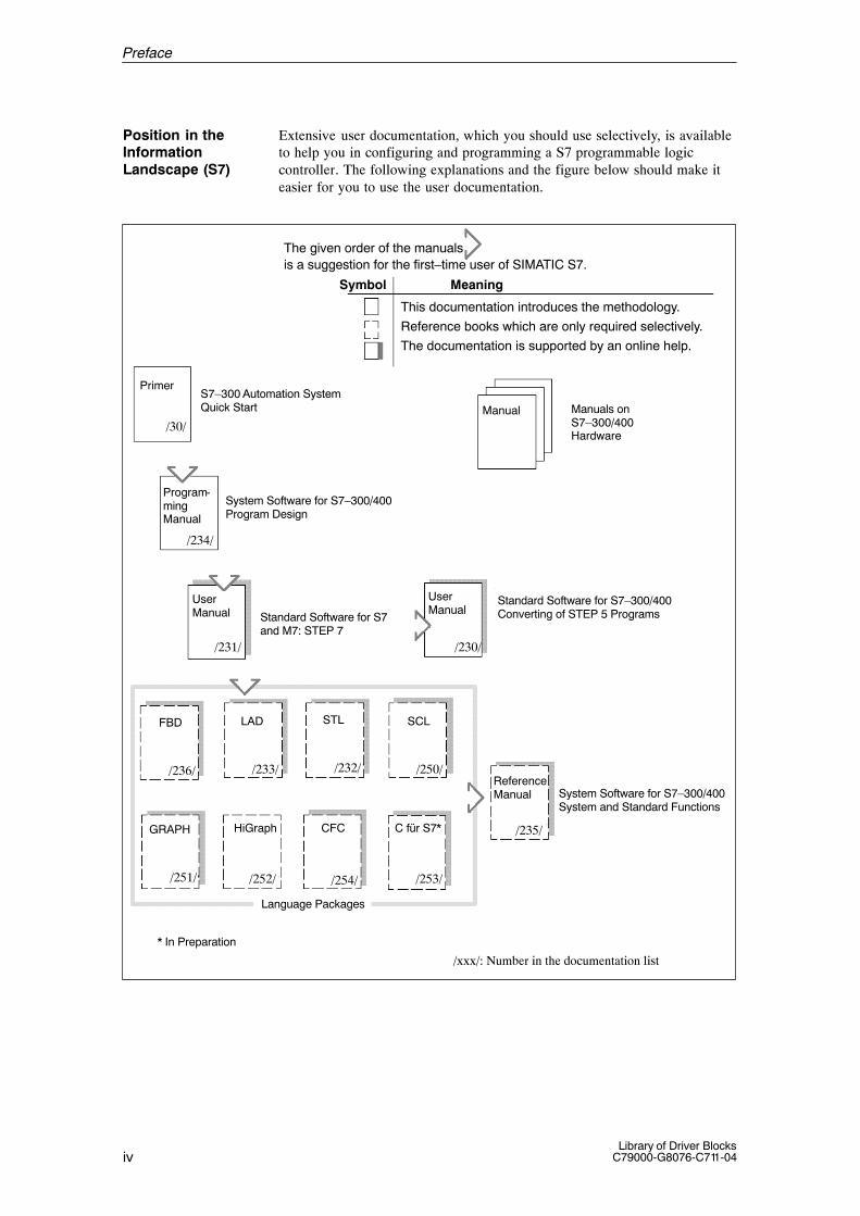
Extensive user documentation, which you should use selectively, is availableto help you in configuring and programming a S7 programmable logiccontroller. The following explanations and the figure below should make iteasier for you to use the user documentation.
The given order of the manualsis a suggestion for the first–time user of SIMATIC S7.
Symbol Meaning
This documentation introduces the methodology.
Reference books which are only required selectively.
The documentation is supported by an online help.
Primer
/30/
S7–300 Automation SystemQuick Start Manual Manuals on
S7–300/400Hardware
Program-ming Manual
/234/
System Software for S7–300/400Program Design
User Manual
/231/
Standard Software for S7 and M7: STEP 7
User Manual
/230/
Standard Software for S7–300/400Converting of STEP 5 Programs
LADFBD
/236/ /233/ /232/
STL SCL
/250/
GRAPH HiGraph CFC C für S7*
ReferenceManual
/251/ /252/ /254/ /253/
/235/
Language Packages
System Software for S7–300/400System and Standard Functions
/xxx/: Number in the documentation list
* In Preparation
Position in theInformationLandscape (S7)
Preface

vLibrary of Driver BlocksC79000-G8076-C711-04
Title Contents
Quick Start The “Quick Start” manual provides an easy introduction into the structure and thesymbolic programming of an S7–300/400. It is particularly suitable for first–timeusers of a SIMATIC S7–300 programmable logic controller.
Programming ManualProgram Design
The programming manual provides you with a basic knowledge of the structure ofthe operating system and of a user program of a S7–CPU. It should be used by thefirst–time user of an S7–300/400 to obtain an overview of the programmingmethodology and to base his or her design of the user program on it.
User Manual STEP 7 The STEP 7 user manual explains the theoretical utilization and the functions of theSTEP 7 programming software package. The manual provides you, as a first–timeuser of STEP 7 as well as an experienced user of STEP 5, with an overview of theconfiguration, programming and starting up of an S7–300/400.When using the software you can access the on–line help, which offers directsupport on detailed questions about using the software.
LAD, STL, FBD, SCLManual1
The manuals of the STL, LAD and SCL language packages contain both the user’sguides and the language description. You only require one of the languages toprogram an S7–300/400, but you can also mix languages within a project, if youwish to. When you use a language for the first time Siemens recommends that youuse the manual to familiarize yourself with the methodology of creating a program.When working with the software you can use the on–line help to obtain answers toall your detailed questions on using the corresponding editors/compilers.
GRAPH1, HiGraph1, CFC1
ManualsThe GRAPH, HiGraph and CFC languages provide you with additional possibilitiesof implementing sequential control systems, state graphs or graphical interconnec-tions of blocks. The GRAPH and HIGraph manuals contain both the user’s guideand the language description. When you use one of these languages for the first timeSiemens recommends that you use the manual to familiarize yourself with themethodology of creating the program.When working with the software you can use the online help (exception HiGraph)to obtain answers to all your detailed questions on using the corresponding editors/compilers.
Reference Manual System and Standard Functions
The S7 CPUs contain system and standard functions integrated in the operatingsystem which you can use when programming. The manual provides you with anoverview of the functions and organization blocks available for S7 as well as (foryour reference) detailed descriptions of interfaces for use in your application.
1 Optional packages for S7–300/400 system software
Preface
viLibrary of Driver Blocks
C79000-G8076-C711-04
This manual is divided into the following groups of topics:
Chapters 1 and 2: Introductory section
� Chapter 1 provides you with information on installing the software.
� Chapter 2 describes the block concept on the basis of an applicationexample. It explains the procedure for selecting the desired blocks as wellas the generally valid properties of the blocks. This information is notrepeated in the detailed information.
� Chapter 3 describes the driver blocks. These are used to read in processvalues present at the input modules, with accompanying information onwhether the hardware or the process values read in are error–free.
� Chapter 4 describes the communication blocks. With these blocks thecommunication is realized between S7–CPU and FM456–4.
As a first–time user use the manual as follows:
1. Read the first two chapters before using the software in order to familiarizeyourself with the terms used and the theoretical procedure.
2. Read the respective overview sections in the other chapters in order to getto know the tasks solved by the respective block group.
References to further documentation are given by using the literaturenumbers in slashes /.../. The list of literature at the end of the manualprovides you with the exact title of the documentation on the basis ofthese numbers.
If you should have any questions on using the software which are notanswered in the paper documentattion or in the on–line help, please contactyour local Siemens partner.
If you have any questions or remarks on this manual please fill out thequestionnaire at the end of the manual and send it to the address given there.Please also enter your personal evaluation of the manual there.
We offer corresponding courses in order to facilitate your familiarization withthe SIMATIC PCS 7 process control system. Please contact your regionaltraining center or the head training center in:
D–90327 Nürnberg, Tel. +49 911 / 895 3154.D–76187 Karlsruhe, Tel. +49 721 / 595 2917.
Structure of thisManual
Conventions
Further Support
Preface

viiLibrary of Driver BlocksC79000-G8076-C711-04
Contents
Preface iii. . . . . . . . . . . . . . . . . . . . . . . . . . . . . . . . . . . . . . . . . . . . . . . . . . . . . . . . . . . . . . . .
Contents vii. . . . . . . . . . . . . . . . . . . . . . . . . . . . . . . . . . . . . . . . . . . . . . . . . . . . . . . . . . . . . . .
1 Installation 1-1. . . . . . . . . . . . . . . . . . . . . . . . . . . . . . . . . . . . . . . . . . . . . . . . . . . . . . . . . . . . . 1.1 Installing and Deinstalling the Block Library 1-2. . . . . . . . . . . . . . . . . . . . . . . . .
2 Block Concept 2-1. . . . . . . . . . . . . . . . . . . . . . . . . . . . . . . . . . . . . . . . . . . . . . . . . . . . . . . . .
2.1 Overview 2-2. . . . . . . . . . . . . . . . . . . . . . . . . . . . . . . . . . . . . . . . . . . . . . . . . . . . . . .
2.2 Application Example 2-9. . . . . . . . . . . . . . . . . . . . . . . . . . . . . . . . . . . . . . . . . . . . .
2.3 SAMPLE: Template 2-12. . . . . . . . . . . . . . . . . . . . . . . . . . . . . . . . . . . . . . . . . . . . . .
2.4 Display Blocks (Overview) 2-17. . . . . . . . . . . . . . . . . . . . . . . . . . . . . . . . . . . . . . . .
2.5 Planning and Programming Display Blocks 2-18. . . . . . . . . . . . . . . . . . . . . . . . .
2.6 Operating and Monitoring with Display Blocks 2-20. . . . . . . . . . . . . . . . . . . . . . .
3 Driver Blocks 3-1. . . . . . . . . . . . . . . . . . . . . . . . . . . . . . . . . . . . . . . . . . . . . . . . . . . . . . . . . . .
3.1 Overview 3-3. . . . . . . . . . . . . . . . . . . . . . . . . . . . . . . . . . . . . . . . . . . . . . . . . . . . . . .
3.2 Deployment of the Driver Blocks 3-6. . . . . . . . . . . . . . . . . . . . . . . . . . . . . . . . . . .
3.3 TM_BEI Binary Input Block 3-10. . . . . . . . . . . . . . . . . . . . . . . . . . . . . . . . . . . . . . .
3.4 TM_BAU Binary Output Block 3-13. . . . . . . . . . . . . . . . . . . . . . . . . . . . . . . . . . . . .
3.5 TM_BU8 Binary Encoder Monitoring Block for 8 Binary Values 3-16. . . . . . . .
3.6 TM_BU16 Binary Encoder Monitoring Block for 16 Binary Values 3-19. . . . . .
3.7 TM_AE Analog Input Block 3-22. . . . . . . . . . . . . . . . . . . . . . . . . . . . . . . . . . . . . . .
3.8 TM_AA Analog Output Block 3-25. . . . . . . . . . . . . . . . . . . . . . . . . . . . . . . . . . . . . .
3.9 TM_E110 Binary Input Block for S5 and TELEPERM M Modules 3-28. . . . . .
3.10 TM_A110 Binary Output Block for S5 and TELEPERM M Modules 3-33. . . . .
3.11 TM_DZ Driver Block for Proportioning Counter Module (2/4 Channels) 3-38. .
3.12 TM_ZE Metering Pulse Input Block 3-48. . . . . . . . . . . . . . . . . . . . . . . . . . . . . . . .
3.13 TM_EG Driver Block for Open-Loop Control Module 3-51. . . . . . . . . . . . . . . . .
3.14 TM_EK Driver Block for Open-Loop Control Module – Valve 3-57. . . . . . . . . . .
3.15 TM_EU, Driver Block for Open-Loop Control Module – Motor 3-66. . . . . . . . . .
3.16 TM_BRBK Driver Block for Binary Arithmetic Module (Coordination Block) 3-74. . . . . . . . . . . . . . . . . . . . . . . . . . . . . . . . . . . . . . . . . . . . .
3.17 TM_ABR Analog Input/Output Block for Binary Arithmetic Module 3-78. . . . . .

viiiLibrary of Driver Blocks
C79000-G8076-C711-04
3.18 TM_TVB Block for Partial Subgroup Control and Preselector Control of Binary Arithmetic Module 3-82. . . . . . . . . . . . . . . . . . . . . . . . . . . . . . . . . . . . . . .
3.19 TM_MSB Block for the ESG Functions “Motor, Valve and Actuator Control” on the Binary Arithmetic Module 3-91. . . . . . . . . . . . . . . . . . .
3.20 TM_RK Driver Block for Single-Channel Closed-Loop Controller Modules 3-101. . . . . . . . . . . . . . . . . . . . . . . . . . . . . . . . . . . . . . . . . . . . . .
3.21 TM_RZ Input Block for Two-Channel Closed-Loop Controller Module 3-113. . . . . . . . . . . . . . . . . . . . . . . . . . . . . . . . . . . . . . . . . . . . . . . . . . . . . . . .
3.22 TM_RZA Output Block for Two-Channel Closed-Loop Controller Module 3-117. . . . . . . . . . . . . . . . . . . . . . . . . . . . . . . . . . . . . . . . . . . . . . .
3.23 TM_S5KE, 3964(R) Linking Receiver Block 3-120. . . . . . . . . . . . . . . . . . . . . . . . .
3.24 TM_S5KS 3964(R) Linking Transmitter Block 3-125. . . . . . . . . . . . . . . . . . . . . . .
3.25 TM_MELD Driver Block for I&C Messages 3-132. . . . . . . . . . . . . . . . . . . . . . . . . .
4 Communication 4-1. . . . . . . . . . . . . . . . . . . . . . . . . . . . . . . . . . . . . . . . . . . . . . . . . . . . . . . .
4.1 Overview 4-2. . . . . . . . . . . . . . . . . . . . . . . . . . . . . . . . . . . . . . . . . . . . . . . . . . . . . . .
4.2 Deployment of the Communication Blocks 4-3. . . . . . . . . . . . . . . . . . . . . . . . . .
4.3 TM_KOM Communication Block 4-4. . . . . . . . . . . . . . . . . . . . . . . . . . . . . . . . . . .
4.4 TM_KST Communication Function 4-6. . . . . . . . . . . . . . . . . . . . . . . . . . . . . . . . .
4.5 Configuration of the Connections 4-7. . . . . . . . . . . . . . . . . . . . . . . . . . . . . . . . . .
4.6 Other Configuration Informations 4-8. . . . . . . . . . . . . . . . . . . . . . . . . . . . . . . . . .
4.7 Data of the Group Interrupt Module 4-9. . . . . . . . . . . . . . . . . . . . . . . . . . . . . . . .
4.8 Error Messages of the FM456 (Communication) 4-10. . . . . . . . . . . . . . . . . . . . .
4.9 Status Word of the Driver Blocks 4-11. . . . . . . . . . . . . . . . . . . . . . . . . . . . . . . . . .
A Technical Data A-1. . . . . . . . . . . . . . . . . . . . . . . . . . . . . . . . . . . . . . . . . . . . . . . . . . . . . . . . .
A.1 Hardware and software requirements A-2. . . . . . . . . . . . . . . . . . . . . . . . . . . . . .
A.2 Block data A-3. . . . . . . . . . . . . . . . . . . . . . . . . . . . . . . . . . . . . . . . . . . . . . . . . . . . . .
A.3 Data types A-6. . . . . . . . . . . . . . . . . . . . . . . . . . . . . . . . . . . . . . . . . . . . . . . . . . . . .
B List of Abbrevations B-1. . . . . . . . . . . . . . . . . . . . . . . . . . . . . . . . . . . . . . . . . . . . . . . . . . . .
C Applicable Documents C-1. . . . . . . . . . . . . . . . . . . . . . . . . . . . . . . . . . . . . . . . . . . . . . . . . .
Glossary Glossary-1. . . . . . . . . . . . . . . . . . . . . . . . . . . . . . . . . . . . . . . . . . . . . . . . . . . . . . . . . .
Contents

1-1Library of Driver BlocksC79000-G8076-C711-04
Installation
This chapter describes how to install the block library by means of theSETUP program.
This chapter deals with the following topics:
Section Describes Page
1.1 Installing and Deinstalling the Block Library 1–2
You require the following software and hardware in order to run the software:
� Windows NT operating system
� Programming device or PC with
– Prozessor 80486 (or higher) and
– RAM memory configuration � 128 Mbytes
� Color monitor, keyboard and mouse, which are supported by MicrosoftWindows NT.
� STEP 7 Standard software
� Hard disk with 4 Mbytes free memory
� At least 1 Mbyte of free memory on drive C: for the setup (setup files aredeleted after completion of the installation).
Overview
In this Chapter
InstallationRequirements
1
1-2Library of Driver Blocks
C79000-G8076-C711-04
1.1 Installing and Deinstalling the Block Library
The software supplied includes a SETUP program which installs the blocklibrary automatically.
The installation is menu-guided. The SETUP program is called up with thestandard procedure under Windows NT for installing software.
The setup program installs the driver blocks for the PLC into thePCS 7_TM \ PCS 7 Driver Blocks library of the SIMATIC S7 catalog.
If the installation program notes that the program has already been installedon the target system, a corresponding message is displayed and the followingalternatives are offered:
� Cancel installation (in order to deinstall the previous software versionunder Windows NT and then to restart the installation) or
� Continue installation and thus overwrite the old version with the new one.
In order to have a clear software structure, Siemens recommends that youdeinstall any existing older versions before installing the new one. Simplyoverwriting an older version furthermore has the disadvantage that, when youdeinstall at a later data, any parts of the older version which may still existare not removed.
For a detailed description on how to install and deinstall the STEP 7 softwarerefer to Section 2.3 of the STEP 7 documentation /231/.
The manual ”CFC for S7 and M7, Graphical Interconnection of Technologi-cal Functions” provides information on how to use the blocks in CFC.
Overview
If a Software Ver-sion has alreadybeen installed ...
Installing and De-installing STEP 7Software
Utilization in CFC
Installation

2-1Library of Driver BlocksC79000-G8076-C711-04
Block Concept
This chapter presents the block concept.Here you learn what a block is and how you can use it to solve automationtasks.
This chapter deals with the following subjects:
Section Topic Page
2.1 Overview 2–2
2.2 Application Example 2–9
2.3 SAMPLE: Template 2–12
2.4 Display Blocks (Overview) 2–17
2.5 Planning and Programming Display Blocks 2–18
2.6 Operating and Monitoring with Display Blocks 2–20
Description of thisChapter
In this Chapter
2

2-2Library of Driver Blocks
C79000-G8076-C711-04
2.1 Overview
The PLC-specific part of configuring a system has an influence on both thehardware and the software. The latter can be programmed or structured usingexisting software. Structuring consists of combining individual elements intoan overall structure which is to fulfil an automation function defined by you.The structural elements which can be used, called blocks afterwards, aresupplied in a collection called ”Block library”.When you use such blocks you can concentrate completely on the automationtask by simply adapting ready-to-use typical partial solutions to your require-ments. The blocks are supplied with a description which details the interfacesand the function of the individual blocks.This description answers any questions you may have on:
� Function (which task does the respective block carry out?)
� Results supplied by the block
� Parameters required by it to this purpose
� Conditions and requirements for its use and error handling
The blocks do not require a special configuration tool. They can be usedsimply through the SIMATIC S 7 editors (CFC, SFC, STL, LAD, SCL).
In order to understand the block concept the block can be regarded as anobject having the following features:
� It has a data interface, called an I/O bar in the description. This isstructured as follows:
– Inputs ( In ): Data which can on the one hand be configured (depen-ding on the plant or function), and on the other hand can have theresults of other blocks applied by interconnecting outputs.These input values are read by the block program and processedfurther. In graphical CFC display mode these are positioned on theleft.
– Controllable inputs ( InOut ): Interacting inputs which be written(activated) by the OS or SFC and to which the block program canwrite back. They are displayed in CFC as inputs.
– Outputs ( Out ): Storage for data which are written by the blockprogram as a result. In graphical CFC display mode these arepositioned on the right.
– Internal parameters which are used by the block program as thememory for interim results (are not displayed in CFC).
� The block has a program, which executes the parameters of the I/O barmentioned above. Generally the values present at the inputs are read,compared, evaluated logically or arithmetically.The result is written to the outputs. The resulting output values can befetched by other blocks.The results corresponds to the function which the block is to fulfil. It isprovided in numerical form (for example in REAL or INTEGER data
Purpose of Blocks
What is a Block?
Block Concept
2-3Library of Driver BlocksC79000-G8076-C711-04
type) or as Boolean information ( 1/0 or TRUE/FALSE). In additionBoolean indicators with respect to its validity are applied to the outputs.These can be scanned by other blocks in order to avoid an invalid endresult in overall processing.
� The interface of the blocks consists of three information groups.Depending on the application it can be a PLC, ES and/or OS block.The information groups include, inter alia the I/O parameters of theblocks and their attributes, the operating and message texts as well as thereferences between the objects. As a rule the information of the threerepresentations have a neutral predefinition. Adapting/changing is carriedout in the context of the ES using the comfortable tools described there(graphical structuring with CFC or SFC, input with checking in block-specific configuration masks, etc.), or in the OS using its tools.When using the block under the standard STEP 7 project planning theblocks must be adapted by using its tools.
The features described above can be summarized as a graphical representa-tion (see Figure 2–1, CFC representation). The parameters of the I/O bar areprovided with a name (in the example INP_1, INP_OP_1, etc.).In the actual block description the name indicates the function/meaning ofthe input/output. There are I/O parameters which are generally valid as wellas program sections which, as a rule, occur in all the library blocks.
� Block type: Designation (or abbreviation) of the block function as, forexample, the symbol table (for example ADD_P).
� Block number: Number of the instance DB. So-called instance DB’smust be created in order to use the blocks. When CFC is used, thisnumber is assigned by it. If you use standard STEP 7 tools for program-ming, you must stipulate this number yourself. The instance DB is used asthe storage for the individual task-specific I/O bar.
� Comment: Block comment (for example, “addition”)
� Execution data: In order to be executed the block must be called from anorganization block (OB). In CFC project planning this call is also deter-mined by the scan rate of the so-called runtime group (see CFC manual).The block is logged on together with others within a runtime group andthis, in turn, in an OB. The runtime group is only executed at every n th
OB start. In graphical CFC display mode the OB as well as the serialnumber of the call within the OB are displayed.When planning a project with standard STEP 7 tools, you must enter theblock call in the relevant OB.
Block Diagram of aBlock
Block Concept
2-4Library of Driver Blocks
C79000-G8076-C711-04
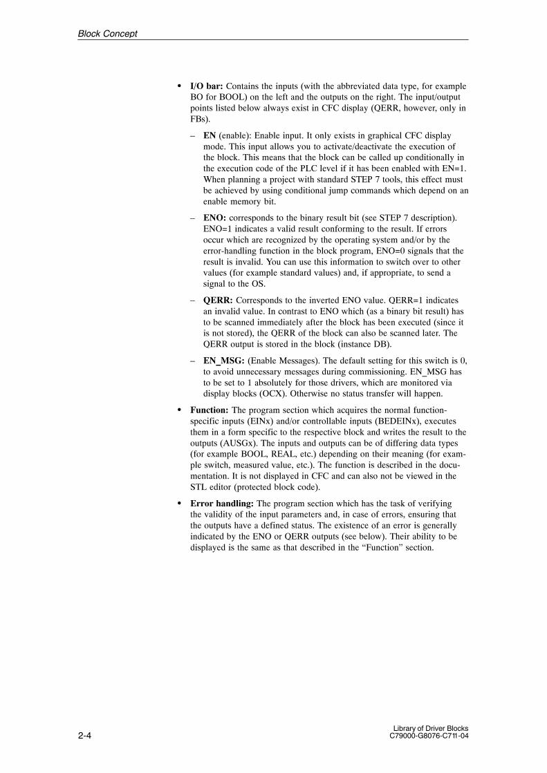
� I/O bar: Contains the inputs (with the abbreviated data type, for exampleBO for BOOL) on the left and the outputs on the right. The input/outputpoints listed below always exist in CFC display (QERR, however, only inFBs).
– EN (enable): Enable input. It only exists in graphical CFC displaymode. This input allows you to activate/deactivate the execution ofthe block. This means that the block can be called up conditionally inthe execution code of the PLC level if it has been enabled with EN=1.When planning a project with standard STEP 7 tools, this effect mustbe achieved by using conditional jump commands which depend on anenable memory bit.
– ENO: corresponds to the binary result bit (see STEP 7 description).ENO=1 indicates a valid result conforming to the result. If errorsoccur which are recognized by the operating system and/or by theerror-handling function in the block program, ENO=0 signals that theresult is invalid. You can use this information to switch over to othervalues (for example standard values) and, if appropriate, to send asignal to the OS.
– QERR: Corresponds to the inverted ENO value. QERR=1 indicatesan invalid value. In contrast to ENO which (as a binary bit result) hasto be scanned immediately after the block has been executed (since itis not stored), the QERR of the block can also be scanned later. TheQERR output is stored in the block (instance DB).
– EN_MSG: (Enable Messages). The default setting for this switch is 0,to avoid unnecessary messages during commissioning. EN_MSG hasto be set to 1 absolutely for those drivers, which are monitored viadisplay blocks (OCX). Otherwise no status transfer will happen.
� Function: The program section which acquires the normal function-specific inputs (EINx) and/or controllable inputs (BEDEINx), executesthem in a form specific to the respective block and writes the result to theoutputs (AUSGx). The inputs and outputs can be of differing data types(for example BOOL, REAL, etc.) depending on their meaning (for exam-ple switch, measured value, etc.). The function is described in the docu-mentation. It is not displayed in CFC and can also not be viewed in theSTL editor (protected block code).
� Error handling: The program section which has the task of verifyingthe validity of the input parameters and, in case of errors, ensuring thatthe outputs have a defined status. The existence of an error is generallyindicated by the ENO or QERR outputs (see below). Their ability to bedisplayed is the same as that described in the “Function” section.
Block Concept

2-5Library of Driver BlocksC79000-G8076-C711-04
INP_OP_1BO
INP_OP_mR
ENBO
BOENO
BOQERR
INP_1I
INP_mDW
ROUTP_1
BOOUTP_k
Block numberBlock typeComment Execution data
Error handling
Function
Is not displayed in CFC, only described in the documentation
Figure 2-1 Block diagram of a block, similar to the CFC display.
The blocks of the present library are classified on the basis of their functionfeatures into the following groups:
� Operating blocks for operating and monitoring via OS. These blocks arerequired to transfer OS-end operations (via the OS block) to the PLCblock and to receive the feedbacks from the operations accepted at thePLC end.
� Alarm blocks used to monitor digital signals and to transmit configuredmessages to the OS. The various process events, which are indicated bychanges in Boolean variables, are monitored by alarm blocks and aresignaled to the OS.
� Function blocks for general arithmetic, open-loop and closed-loopcontrol tasks. These are used to solve the regular tasks of the PLC.
� Converter blocks which convert the various data types in order to allowthe exchange of data. Values can only be transferred between outputs andinputs of different data types in CFC (for example, from a REAL value toan INTEGER value) after they have been converted.
� Driver blocks to exchange information between the process signals (viaI/O modules) and the parameters of the I/O bar of other blocks. Throughthese blocks you can handle the process values in the physical unitdesired by you or react in a defined manner to faults occurring inprocess-data processing.
How to Find theSuitable Block
Block Concept

2-6Library of Driver Blocks
C79000-G8076-C711-04
This section lists the common abbreviations used as names for the inputs andoutputs of the blocks listed above. These are intended to help you identify themeaning of the input/output parameters. As a rule the designation of a para-meter consists of an abbreviation of the corresponding English term, limitedto a maximum of 8 characters. The character ”_” can also be used as a sepa-rator, provided the maximum length of 8 characters is not exceeded. An ex-ception is formed by the designations of controllable inputs, which are repre-sented differently (graphically) anyway in the OS block. The middle columnof the table lists the preferred data type which is to be used for this abbrevia-tion. No data type is stipulated for analog parameters here (they can be ofdata types REAL, INTEGER, etc.).In the column Meaning the typical use of the block in/outputs is explained.
Table 2-1 Naming Convention for I/O Bars
Abbreviation Parameter ofData Type
Meaning
Q BOOL Output Bool
Q_ BOOL Output Bool; for example in order to differen-tiate between an input or a REAL value
_HLM High Limit
_LLM Low Limit
_ALM Alarm
_WRN Warning
_H_ALM high alarm
_L_ALM low alarm
_H_WRN high warning
_H_TOL high tolerance
_L_TOL low tolerance
_ON BOOL Switch ON; default 0; activate function
_OFF BOOL Switch OFF; default 1; deactivate function
_SEL BOOL Selector; Switch function
I BOOL Input Bool; meaning cannot be specified moreexactly
I_ BOOL Input Bool; for example to differentiatebetween other inputs or REAL values
IN ANY Input ANY without Bool; meaning cannot bespecified more exactly
OUT ANY Output ANY without Bool; meaning cannot bespecified more exactly
_OP IO Operation; Extension for all operable I/Ovariables, even if the name is longer than8 characters!
OP BOOL Operation
MON BOOL Monitoring
Convention forNaming I/O Bars
Block Concept

2-7Library of Driver BlocksC79000-G8076-C711-04
Table 2-1 Naming Convention for I/O Bars
Abbreviation MeaningParameter ofData Type
_ Separator used to facilitate reading. If the nameis too long, the underscore can be dropped
_MAN_ Manual value
_AUT_ Automatic value
_INT_ Internal value
_EXT_ External value
_RE_ Remote; when there is a choice between thecomputer and for example the I/O (for exampleon the case of controller variables)
SP_ Setpoint
PV_ Process variable; measured value or processvariable
LMN_ (Loop) manipulated variable; manipulatedvariable or analog output signal to be output
DISV_ Disturbance variable
ER_ Error; error signal, fault
GAIN Kp parameter of the closed-loop controller
TI Integration value at an integrator or additivecontrol algorithm
TD Differentiation value at a differentiator oradditive control algorithm
TN Integral-action time at a multiplying controlalgorithm
TV Derivative-action time at a multiplying controlalgorithm
TM_LAG T1 Time lag
The inputs and outputs of the TM I/O driver blocks are different to theconvention described above. For the reason of compatibility, the oldparameter names were retained as well as possible.
Convention forNaming I/O Barsof TM Blocks
Block Concept
2-8Library of Driver Blocks
C79000-G8076-C711-04
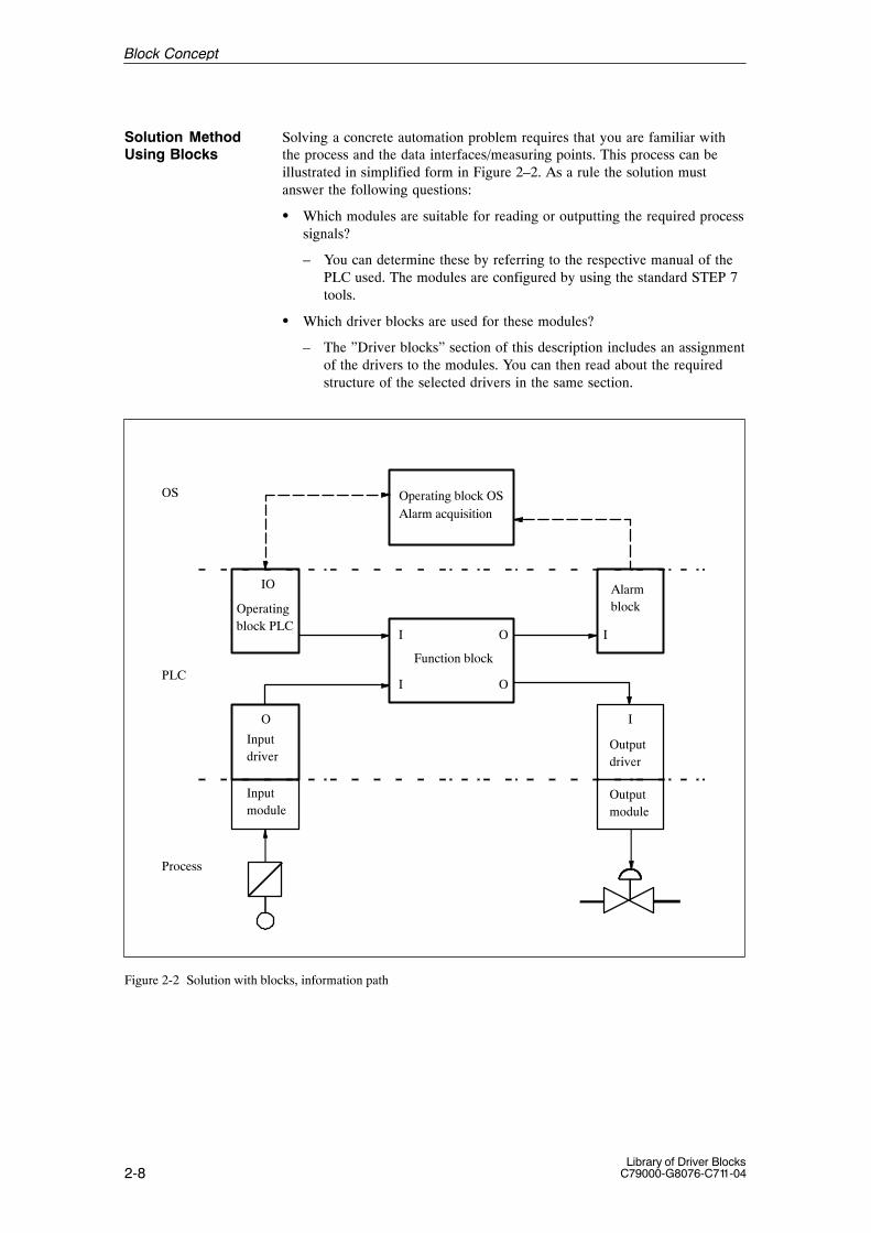
Solving a concrete automation problem requires that you are familiar withthe process and the data interfaces/measuring points. This process can beillustrated in simplified form in Figure 2–2. As a rule the solution mustanswer the following questions:
� Which modules are suitable for reading or outputting the required processsignals?
– You can determine these by referring to the respective manual of thePLC used. The modules are configured by using the standard STEP 7tools.
� Which driver blocks are used for these modules?
– The ”Driver blocks” section of this description includes an assignmentof the drivers to the modules. You can then read about the requiredstructure of the selected drivers in the same section.
OS
PLC
Process
Operating block PLC
Alarm block
Function block
Input driver
Input module
Output module
Operating block OSAlarm acquisition
Output driver
IO
I
I
O
O
I
O I
Figure 2-2 Solution with blocks, information path
Solution MethodUsing Blocks
Block Concept

2-9Library of Driver BlocksC79000-G8076-C711-04
2.2 Application Example
The procedure described above is to be explained in more detail by means ofa concrete task.A simple temperature control unit is to be created. The temperature range isfrom 0 to 200 oC. The setpoint range of 140 to 160 oC, is to be set by theoperator. The closed-loop controller is only operated in automatic mode.If a temperature of 170 oC is exceeded, an alarm message is to be transmittedto the OS.
Let us assume that the PLC hardware has already been configured by meansof STEP 7 tools, meaning that it is already known which analog input or out-put modules are to be used, in which rack and in which slot they are installedand to which module channel the respective temperature sensor or actuator(control valve) is connected.Under this assumption the software can be structured under CFC.If, however, you deploy the blocks under simple STEP 7 tools (STL), youmust program the interconnections, parameter assignments, assignments ofvarious memory bit as well as calls of the blocks in the corresponding OBs.In both cases you do not have to program and debug the various functionsused.
� Driver use
– Block TM_AE is selected from the ”Driver block” section to read thetemperature (the assumed analog input module is supported by it).
– Block TM_AA is selected from the ”Driver block” section to outputthe manipulated variable of the closed-loop controller (the assumedanalog output module is supported by it).
– Note module number of the modules used (these were defined whenconfiguring the hardware with STEP 7 tools in DB1), the channelnumber and the measuring range of the connected process signals.These data must be used when structuring the individual drivers.
Although the description of the further procedure is the same for CFC confi-guring and STEP 7 programming, the concrete handling differs, dependingon the configuring tool used.The following sections describe the procedure when using CFC for this task(as the standard tool for planning projects on industrial processing plants).For details on using CFC or on project management, please refer to the CFCmanual.
� Create a CFC chart in the chart container of your project. Use a namewhich corresponds to the task (for example, TICA_123).
� Define one instance for each of the block types selected before (in ourexample one each of TM_AE, TM_AA, TM_KOM, TM_KST, REGLER,LIMITS_P, OP_A_LIM and MESSAGE block).
Task
Block Selection
Configuring theBlocks
Block Concept

2-10Library of Driver Blocks
C79000-G8076-C711-04
� Log all the instances on in a common watchdog interrupt OB forprocessing (CFC key word ”Runtime properties”. When defining thecall sequence of the blocks from the OB, observe the general rule”Retrieval –> Execution –> Output”.In order to define the sequence, you must first define for each blockwhere it gets its parameters from. As a rule it must be installed after allother blocks from which it obtains interconnected values. bezieht.In our example this means:TM_KST, TM_AE, OP_A_LIM, REGLER, LIMITS_P, MESSAGE,TM_AA, TM_KOM.
Notice
Blocks which also have to be installed in other OBs (for example driverblocks), are installed automatically by CFC at those points. If you use simpleSTEP 7 programming tools (STL or SCL), you have to program the OBsrequired and call the respective same instance of the function block in eachOB.The required OBs can be found in the documentation at the respective blockdescription as well as in the ”Technical Data” appendix.
� Interconnect the outputs of the blocks which supply values with thecorresponding inputs of the blocks which process these values further.
� At each instance assign parameters to the inputs whose initial values haveto be adapted to concrete process requirements. In our example thisapplies at least to the following parameters:
– TM_AE: BGNR, KNR
– OP_A_LIM: U_HL, U_LL
– CONTROL: Adapt GAIN, TN, TV and TM_LAG to thecontrolled-system behavior
– LIMITS_P: V_HL
– MESSAGE: Message text for OS
– TM_AA: BGNR, KNR
� Interconnect the outputs to the inputs in accordance with the diagram inFigure 2–3.
� Enable the I&C messages of the blocks TM_AE and TM_AA viaEN_MSG.
� Generate the PLC code and load it into the PLC. Debug the structureusing the online debugging tools.
Block Concept

2-11Library of Driver BlocksC79000-G8076-C711-04
Notice
Our simple example did not provide for a reaction to error messages fromthe individual blocks. Our example could be extended by insertingSEL_REAL blocks at various points in the structure. These can be intercon-nected to the error outputs of the blocks (ENO or QERR) in order to providea safety/substitute value for further processing.
TM_AE
X
OP_A_LIM
VU
CONTROL
LMNSP_INT
QVHLU
LIMITS_P
I_1
MESSAGE
X
From theinput module
To theoutput module
OB32
To the OS
PV_IN
From
TM_AA
the OS
Figure 2-3 Interconnection example
Block Concept

2-12Library of Driver Blocks
C79000-G8076-C711-04
2.3 SAMPLE: Template
The following example explains the general form of the description of ablock. This will help you to find the information desired rapidly whenreading the descriptions of the individual blocks.
SAMPLE is the type name of the block and must be unique within theproject. Template is the brief description of the task/function of the block.
FB x
The abbreviation for the block type (in our example FB) can be:
� FB Function block
� FC Function
� ES block which is handled as such in the ES (CFC chart). When transfer-red to the PLC only the corresponding inline code is inserted into the cal-ling OB. STEP 7 tools do not identify it as a block.
x Block type number
This provides details on the organization blocks into which the written blockis to be installed. When using CFC you only have to install it in the normalOB for the actual task (while observing the principle ”Read–>Process–>Output”). Installation in the remaining OBs is carried out by CFC, whichcreates the required OBs while compiling.Check this while commissioning, since you could by mistake remove theblock while installing/removing it in the execution sequence (while changingthe sequence, etc.).If you use the blocks under STL or SCL, you have to program these OBs andcall the instance of the block in them.
This describes the function of the block briefly.In the case of complex blocks further information is provided in the Methodof operation section.
Further information on the function of the individual inputs, operatingmodes, time sequences, etc. You should know the contexts described herein order to use the block effectively.
Introduction
Title
Type/Number
Calling OBs
Function
Method ofOperation
Block Concept

2-13Library of Driver BlocksC79000-G8076-C711-04
Errors are indicated in the CFC chart at the Boolean block output ENO.The value corresponds to the binary result bit (binary result in STEP 7 STLafter the block has been terminated) or to the OK bit (in SCL format) and hasthe following meaning:
� ENO = binary result bit = OK = 1 (TRUE) –> The block result is OK.
� ENO = binary result bit = OK = 0 (FALSE) –> The result or the requiredconditions for its calculation (for example, input values, operating mode,etc.) are invalid.
In the case of FBs the inverted binary input bit is additionally stored in theQERR output of the instance DB.
� QERR = NOT ENO
Notice
The following applies when programming in STL:– ENO / The binary result bit can only be evaluated immediately after the
block has been executed, since it can be influenced by the subsequentSTEP 7 instructions. It is the typical error indicator of the FCs or ES blocks.
– QERR is stored in the instance DB of an FB and can also be scanned later.
Error indication arises by two independent means:
� The operating system recognizes a processing error (for example: valueoverflow, called system functions supply an error code with binary inputbit = 0).This is a function of the system and is not mentioned expressly in theindividual block descriptions.
� The block algorithm checks values and operating modes for theirfunctional legality. These error cases are documented in the descriptionof the block.
The evaluation of the error indication can be used, for example, to generatemessages (refer to the section on alarm blocks) or to utilize substitute valuesfor invalid results.
The error output QPARF indicates a parameterization error (permissiblerange of values exceeded). If TRUE, no processing of the block function isdone.The output BGF indicates a hardware fault (module not plugged, modulefaulty, etc.). The detailed cause is displayed via I&C alarm messages.
A difference is made between:
� Initial startThe block is called for the first time from the OB in which it has beeninstalled. As a rule this is the OB in which normal, process-specificprocessing occurs (for example: the watchdog interrupt OB).The block enters the state corresponding to the input parameters. Thesecan be initial value (refer also to the I/O bar) or values which you havealready configured, for example in CFC. The initial-start behavior is notdescribed separately unless the block deviates from this rule.
Error Handling
StartCharacteristics
Block Concept

2-14Library of Driver Blocks
C79000-G8076-C711-04
� StartupThe block is executed once during a CPU startup. This ensures that theblock is called up from a start-up OB (where it is installed automaticallyby the ES or has to be installed manually by using STEP 7).In this case the start-up characteristics are described.
A block with these characteristics must be installed into a watchdog interruptOB. It calculates its time constants/parameters on the basis of its samplingtime (the interval between two consecutive cyclic processing steps).When configuring in CFC on an ES the sampling time is also defined throughthe scan rate of the so-called runtime group. This ensures that the block is notexecuted during every OB run.
The time characteristics are only mentioned if the block indicates them.
A block having these characteristics signals events to the primary OS. If theyexist, the parameters required to generate messages are documented.Block not having message characteristics can be complemented by additionalalarm blocks. A reference to the message characteristics in contained in thedescription of the individual blocks capable of signaling.
If the block has operating and monitoring possibilities on OS, thecorresponding OS components and their structuring are described.Other block types can be complemented by these, thus enabling themalso to be operated.
The individual blocks only contains deviations from or supplements to thegeneral rules. These general rules are explained below.The following points must be checked or set by using ES debugging means inorder to ensure that the block can fulfil its assigned function:
� PLC is in RUN mode.
� The block is called in the correct OB:
– With time characteristics, in a watchdog interrupt OB (for exampleOB32).
– With start-up characteristics, additionally in the start-up OB (OB100).
– Driver block, additionally in the interrupt OBs specified there.
� The enable input is set (EN=1, only for CFC configuration).
� The primary runtime group of the block is enabled (only CFC).
� The block does not indicate an error (ENO=1 or QERR=0). If this is notthe case, eliminate the cause of the error indication (this is described inthe error-handling section).
� The results/output values correspond to the input values and the setoperating modes (the block functions correctly).
The I/O bar provides the data interface of the block. In addition you cantransfer data to the block and fetch results from the block.
TimeCharacteristics
MessageCharacteristics
Operating andMonitoring via OS
Starting Up
I/O Bar
Block Concept

2-15Library of Driver BlocksC79000-G8076-C711-04
Table 2-2 I/O bar of the SAMPLE block
Element Meaning Type Default Kind Attr. O&M Valid values
EN Enable BOOL 1 I Q
U1 Addend 1 REAL 0 I Q + > 0
etc.
ENO Test output1: Processing o.k.
BOOL 0 O
Table 2–2 lists all the input and output parameters of the block type, whichthe user can access with the configuration tools. Elements which can only beaccessed from the algorithm of the block are not listed (so-called internalvariables).The columns have the following meaning:
� Element = Symbolic name of the parameter as it is shown in the chartdisplay of the CFC. Due to the SCL syntax it can deviate from the nameusual for its function.
� Meaning = Function (possibly brief description)
� Type = Data type: The following data types occur in the I/O bar:
Table 2-3 Data types in the I/O bar
Data Type Bit length Range Application
BOOL 1 0/1 or FALSE/TRUE Switches and displays
BYTE 8 16#00 to 16#FF Drivers, subnet IDs
WORD 16 16#0000 to 16#FFFF Drivers, rack numbers
DWORD 32 16#00000000 to 16#FFFFFFFF Batch blocks, Batch IDs
INT 16 –32738 to 32767 Selection parameters
DINT 32 –2147483648 to 2147483647 Counter parameters
REAL 32 –3.402822E+38 to –1.175495E–38or 1.175495E–38 to 3.402822E+38
Process values and theircalculated results
STRING[n 8 x (n+1) Characters (texts) BATCH flexible blocks withdynamically-assigned texts
ANY 320 Interconnection information (pointers) Alarm blocks, interconnectioninput for any secondary values
Block Concept
2-16Library of Driver Blocks
C79000-G8076-C711-04
� Default value = Value of the parameter, if it is not changed byconfiguration or by the algorithm.
� Type = Kind of access of the block algorithm to the parameter:
– I = Input; the algorithm reads the parameter.
– O = Output; the algorithm writes the parameter.
– IO = Input and output; the algorithm reads the parameter and, ifappropriate writes a different value back (typical for OS-operableparameters).
� Attributes = Additional features of the parameter.Input parameters can, as a rule, be configured.Output parameters cannot be configured and can be transferred via aninterconnection to an input of the same data type.Additional properties (attributes) are indicated as follows:
– Q = The parameter can also be interconnected in CFC.
– B = The parameter can be operated via the OS.
– U = The parameter is invisible in CFC display and is configured auto-matically by the ES. It must be configured manually by the STEP 7user, if no ES is used.
� Valid values = Additional limitation within the data-type range.
� Operating and Monitoring = The parameters marked with a ”+” can beoperated and monitored from the corresponding display block of the OS.
Note
The input EN (1: Enable processing of the block) as well as the output ENO(0: Error in the block processing or block not enabled) only exist in the CFCdisplay (applies to all the blocks in the library). They are therefore no longerdisplayed in the I/O bar.
Notice
An input parameter which has the attribute Q can be interconnected.If it must be possible to operate it with OS means, then a correspondingoperating block must be interconnected. It can then obtain values either byoperation or through the interconnection and transfer it to the input mentioned. If an interconnected parameter is nevertheless operated directly,it is overwritten by the interconnection when the block is processed the nexttime.
Block Concept
2-17Library of Driver BlocksC79000-G8076-C711-04
2.4 Display Blocks (Overview)
In order to use the display blocks, you require a system with WinCC and the“Basis Process Control” control system package.
The display blocks are designed for graphics boards with a resolution of 1280 x 1024 pixels.
For the operator the display blocks form the window to the PLC blocks withwhich a system is automated. Every display block has exactly one PLC blockassigned to it.
The display blocks offer the user the following functions:
� Operation of the process / Configurations
� Monitoring of the process
The display blocks offer the user the following advantages:
� Easy to learn
� Simple project planning through defined interface between display blockand PLC block
� Simple handling thanks to few operating rules
� Structured display of the process
� Conforms to WinCC and Windows
The display blocks can be displayed in two different formats. You can choosebetween the following views:
� Group display (Control field)
� Loop display
The group display offers a detailed view of the respective PLC block.
The loop display shows an overall view of all the bodies of a display block.
Prerequisites
Purpose of DisplayBlocks
Advantages ofDisplay Blocks
Display Forms ofthe Display Blocks
Group Display
Loop Display
Block Concept

2-18Library of Driver Blocks
C79000-G8076-C711-04
2.5 Planning and Programming Display Blocks
This section shows you how to plan display blocks. The display blocks arerealized as OLE Control units and are installed under WinCC by means ofthe object palette.
The display blocks are planned in a Graphics Designer window. Proceed asfollows:
� Select and position the display block
� Assign general properties
Proceed as follows:
� Select the ”OLE Control” object from the ”Smart Objects” object menu.
Result: The cursor has the extension ”OCX”.
� Position the cursor and press the left-hand mouse button at the desiredposition on the screen and drag the mouse diagonally while holding theleft-hand mouse button. Release the mouse button.
Result: A rectangular window is displayed and an “Ole Control Insert”dialog box is opened.
� From the dialog box select the desired display block and confirm yourchoice by clicking on the OK button.
Result: The selected display block is inserted into the rectangular window.
� Use the left-hand mouse button to position the block window at thedesired location in the work area.
Double-click in the block window to open the properties box of the displayblock.
Configuration field. This consists of:
� Tag name (measuring point name, can be masked or unmasked)
� Operating authorization: Here you give the operating authorization forparameter groups as described at the block.
� Language: Here you select the language, in which the static texts aredisplayed.
Overview
Planning theDisplay Blocks
Selecting andPositioningDisplay Blocks
Assigning GeneralProperties
Block Concept
2-19Library of Driver BlocksC79000-G8076-C711-04
You can adapt the size of the graphic in the graphics display box.
The size of the graphics preview box can be changed by entering values inthe ”Width” and ”Height” boxes. The values are entered as pixels. Confirmthe values entered by clicking on the ”Apply” button.
You can change the size of the graphics within the graphics preview box bygrabbing the rectangular graphics at the edges or corners and dragging themouse horizontally, vertically or diagonally while keeping the left-handmouse button pressed.
If several graphics overlap in the graphics preview box, the graphic isdisplayed completely whose assigned parameter is uppermost in theparameter list in the configuration box. Covered graphics can therefore bedisplayed completely by moving the assigned parameter to the top of theparameter list. The parameters can be moved by dragging with the mouse.
Proceed as follows to remove the assignment of a graphic to a parameter:
Point on the corresponding graphic in the configuration box and open adialog box by clicking on the right-hand mouse button. Click on ”OK”.The graphic is removed from the configuration box and assignment deleted.
Adapting the Sizeof the Graphics
Removing theAssignment ofGraphics
Block Concept

2-20Library of Driver Blocks
C79000-G8076-C711-04
2.6 Operating and Monitoring with Display Blocks
This section shows you how to use the display blocks to change processvalues and parameters and monitor the process.
The operating boxes (input boxes) are displayed as boxes with a white back-ground. The boxes with a gray background are purely information boxes andcannot be operated.
In order to exclude wrong operation as far as possible, process operationcontrols and parameter changes always need to be confirmed by the operator(two-stage operation). The entered value is not written to the correspondinginput of the PLC block until it has been confirmed (exception: steppingmode).
Proceed as follows for operation/configuration:
� Open the dialog box for entering the value by
– Selecting the corresponding panel in the control field.
� Enter the new value in the operable box or click on the % buttons.
� Click on the OK button.
Result: The software checks whether the value is permitted. If the upperor lower limit is exceeded, a warning box is displayed. If the value lieswithin the limits, it is written to the PLC block. If a bar is displayed, itadapts itself to the new value.
The dialog box is closed and the value is not written to the PLC block if the”Cancel” button is activated or if the operation monitoring time of 15 s isexceeded.
In stepping mode click on the buttons provided in the dialog box. The valuewhich has been changed by the corresponding percentages is written into thePLC block without confirmation. After the stepping buttons have beenactiva-ted, you can close the dialog box by clicking on the ”Cancel” or ”OK” but-ton.
Figure 2-4 Display example of a dialog box
Overview
Where isOperatingCarried Out?
How to Operate
Block Concept
2-21Library of Driver BlocksC79000-G8076-C711-04
The operable and monitorable boxes in the various bodies of the displayblocks have a unique assignment to the input and in/out parameters of thePLC blocks. This interdependence is represented in the sections on theindividual PLC blocks.
Operator intervention in process values and the changing of parameters isonly possible with a certain user authorization. The authorization levels arecontained in the login of the respective user and are assigned in WinCC.
The display blocks use up to three authorizations levels controlled byparameters.They are defined at configuring the display blocks.
The assignment of the authorization levels is described at the individualdisplay blocks.
The values in the PLC block which are relevant for operating and monitoringare shown in the display block in the various bodies. Various forms, such asanalog values, bars, curves, etc., are available for displayed values.
The upper and lower limit can be set. The ”Limit” body only represents thelimits graphically and cannot be operated. The upper and lower limits of theobjects can only be set by entering values in the corresponding windows, nothowever by dragging with the mouse.
The analog values are displayed as floating-point values as follows:
� Positive values: Max. of five digits and decimal point
� Negative values: Negative sign, max. of four digits anddecimal point
� Overflow: grey
� Leading zeroes: are suppressed
� Invalid values: ”*****”(for example PLC failure)
If an operator has the authorization to operate a unit, this automaticallyentails the right to monitor all the display blocks belonging to this unit.
Assignment to theBlock Parameters
Authorization toOperate
Monitoring
Analog Value Dis-play
Authorization toMonitor
Block Concept

2-22Library of Driver Blocks
C79000-G8076-C711-04
Every process operation control/configuration is logged by the WinCCsignaling system. The following values are transferred to the signalingsystem:
� Time of the operator intervention (date, time)
� Alarm type
� Incoming signal
� Parameter name
� Previous value
� New value
� Batch designation
� Measuring point identifier
� Area
� Batch name
� Operating text
� Name of the logged operator
� Unit
Logging ofOperatorInterventions
Block Concept

3-1Library of Driver BlocksC79000-G8076-C711-04
Driver Blocks
This chapter describes the driver blocks.It tells you how they can be used with corresponding hardware to readprocess signals into the PLC or output them from the PLC.
The driver blocks
� Transfer process data between the I/O peripherals and the arithmeticblocks
� Supply diagnostic data on the addressed I/O
This chapter deals with the following subjects:
Section Describes Page
3.1 Overview 3-3
3.2 Deployment of the Driver Blocks 3-6
3.3 TM_BEI Binary Input Block 3-10
3.4 TM_BAU Binary Output Block 3-13
3.5 TM_BU8 Binary Encoder Monitoring Block for8 Binary Values
3-16
3.6 TM_BU16 Binary Encoder monitoring Block for16 Binary Values
3-19
3.7 TM_AE Analog Input Block 3-22
3.8 TM_AA Analog Output Block 3-25
3.9 TM_E110 Binary Input Block for S5 and TELEPERM MModules
3-28
3.10 TM_A110 Binary Output Block for S5 and TELE-PERM M Modules
3-33
3.11 TM_DZ Driver Block for Proportioning CounterModule (2/4 Channels)
3-39
3.12 TM_ZE Metering Pulse Input Block 3-47
3.13 TM_EG Driver Block for Open-Loop ControlModule
3-50
3.14 TM_EK Driver Block for Open-Loop ControlModule – Valve
3-55
3.15 TM_EU Driver Block for Open-Loop ControlModule – Motor
3-62
Description ofthis Chapter
In this Chapter
3
3-2Library of Driver Blocks
C79000-G8076-C711-04
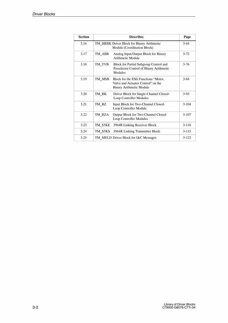
Section PageDescribes
3.16 TM_BRBK Driver Block for Binary ArithmeticModule (Coordination Block)
3-68
3.17 TM_ABR Analog Input/Output Block for BinaryArithmetic Module
3-72
3.18 TM_TVB Block for Partial Subgroup Control andPreselector Control of Binary ArithmeticModules
3-76
3.19 TM_MSB Block for the ESG Functions “Motor,Valve and Actuator Control” on theBinary Arithmetic Module
3-84
3.20 TM_RK Driver Block for Single-Channel Closed-Loop Controller Modules
3-93
3.21 TM_RZ Input Block for Two-Channel Closed-Loop Controller Module
3-104
3.22 TM_RZA Output Block for Two-Channel Closed-Loop Controller Modules
3-107
3.23 TM_S5KE 3964R Linking Receiver Block 3-110
3.24 TM_S5KS 3964R Linking Transmitter Block 3-115
3.25 TM_MELD Driver Block for I&C Messages 3-122
Driver Blocks

3-3Library of Driver BlocksC79000-G8076-C711-04
3.1 Overview
The S7 CPU conceals the hardware dependence of access to the I/Operipheral and allows direct access to the I/O peripheral.Process instrumentation and control systems place other requirements onsignal processing. This also includes test information for every hardwaresignal such as module/channel errors.In order to fulfil these requirements, the library offers driver blocks whichimplement the interface to the hardware including the test functionality.
The table provides an overview of the drivers with the correspondingmodules.
Table 3-1 Overview of the driver blocks with the corresponding modules
FB blockNo.
Block typename
Module designation(MLFB Number)
Corresponding module
301 TM_BEI 6DS1 601/602/615 Binary input modules
302 TM_BAU 6DS1 603/604/605 Binary output modules
303 TM_BU8 6DS1 620/621 Binary input modules, 8 binary values
304 TM_BU16 6DS1 600 Binary input module, 16 binary values
305 TM_AE 6DS1 700/701/703/713/730/731/321
Analog input modules
306 TM_AA 6DS1 702/321 Analog output modules
307 TM_E110 6DS1 310/601/602 Binary input modules for S5–110A linking
308 TM_A110 6DS1 310/321/603/604/605
Binary output modules for S5–110A linking
309 TM_DZ 6DS1 613 Proportioning counter module
310 TM_ZE 6DS1 607 Metering pulse input module
311 TM_EG 6DS1 504/505 Open-loop control module
312 TM_EK 6DS1 501/503 Open-loop control module for actuator (valve)
313 TM_EU 6DS1 500/502 Open-loop control module for motor
314 TM_BRBK 6DS1 717 Binary arithmetic module, coordination
315 TM_ABR 6DS1 717/720 Binary arithmetic module, analog input/output
316 TM_TVB 6DS1 717 Binary arithmetic module, partial subgroup control andpreselector control
317 TM_MSB 6DS1 717 Binary arithmetic module, open-loop control functions
318 TM_RK 6DS1 400/401 Closed-loop controller module, single-channel
319 TM_RZ 6DS1 402/403 Closed-loop controller module, two-channel, input
320 TM_RZA 6DS1 402/403 Closed-loop controller module, two-channel, output
321 TM_S5KE 6DS1 333 Interface module for S5–PLCs, receiver
322 TM_S5KS 6DS1 333 Interface module for S5–PLCs, Transmitter
323 TM_MELD 6ES7961-1AA00-0AC0 Cabin I&C messages
Purpose of DriverBlocks
ModuleAssignment
Driver Blocks

3-4Library of Driver Blocks
C79000-G8076-C711-04
The driver block requires the following information from its correspondingmodule:
� Module number
� Channel number. It corresponds to the channel number in the module.Numbering begins with ”0”, both for the module and for the driver. Thisis configured at the KNR input of the driver.
The driver tests the validity of the configured module and channel number.This test is carried out during the startup and when the configuration ischanged.If the test is negative, the output QPARF (parameter assignment error) is setand no further I/O access is carried out until this state is corrected.
The following utilities are offered by SIMATIC S7 for module testing:
Table 3-2 SIMATIC S7 utilities for module testing
OB Event Remark
OB40 Hardware interrupt Is accessed when a module capable of interrupting triggers an interrupt(only relevant for common interrupt module 6DS16..).
:
OB47 Hardware interrupt as for OB40 (see above)
OB100 Cold restart Is accessed when a cold restart is required.
Notice
The OBs listed in Table 3–2 must be loaded in the PLC. Otherwise it willcall the respective OB when one of the triggering events occurs. If the OB isnot available, the PLC changes to STOP mode. When configuring with CFCthis is carried out automatically, if you use driver blocks. If you use simpleSTEP 7 tools, you must program these OBs, so that they call the respectivedriver instances (see also the note below).
Module Test /Startup
Driver Blocks

3-5Library of Driver BlocksC79000-G8076-C711-04
Notice
The driver blocks all have the properties ”Start-up characteristics” and ”Testbehavior”. The latter is necessary in order to be able to react with definedresults to the various error responses to the hardware used as well as topossible incorrect configurations. The driver blocks (with the same instance)must therefore be installed not only on the normal processing level but alsoin the OBs mentioned above. When configuring with CFC you only have toinstall the driver in the normal OB. The additional installation in the otherOBs is carried out by CFC. Different code parts in the block are accesseddepending on whether the calling OB is the start-up OB, the diagnostic OBor an other OB.When programming with STL or SCL you have to program the required OBsand call them the respective driver instance in them.
The PCS 7 block ALARM_8P is used to generate control-system messages.The block must be provided with an alarm number. When configuring withCFC the respective input EV_ID is assigned automatically. When configuringwith STEP 7 on the other hand, you have to use the PMC-PRO message pak-kage to carry this out yourself.
The signal is sent with the event class S (control-system error) to the OS (ifenabled by EN_MSG = 1).
Alarm Behavior
Driver Blocks
3-6Library of Driver Blocks
C79000-G8076-C711-04
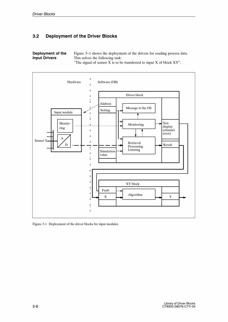
3.2 Deployment of the Driver Blocks
Figure 3–1 shows the deployment of the drivers for reading process data.This solves the following task:”The signal of sensor X is to be transferred to input X of block XY”.
Simulationvalue
Result
Monitoring
RetrievalProcessingLimiting
Driver block
Input module
XY block
X Y
A
D
Monito-ring
Hardware Software (OB)
Testdisplay(channelerror)
Sensor X
Message to the OSSetting
AlgorithmFault
Address
Figure 3-1 Deployment of the driver blocks for input modules
Deployment of theInput Drivers
Driver Blocks
3-7Library of Driver BlocksC79000-G8076-C711-04
Proceed as follows:
� Determine the module and channel numbers as well as the moduledesignation of the module to which the sensor is connected.
� Select the suitable type of driver for this module (see Table 3–1).
� Define an instance of this driver block (instance DB) and call this in theOB before the block which processes the driver results further.
� Assign parameters to the inputs of the driver with the required data.At least the following parameters of the input driver must be adapted(changing the initial setting) in order to access the signals connected toinput module:
– BGNR and possibly KNR (depending on the modules plugged into therack)
All other parameters must be adapted in accordance with the individualsignals.
� As a test function you must also install the driver in other OBs (see Table3–2, with the corresponding information).
Figure 3–1 summarizes the various input/output parameters under:
� Input parameters
– Address: BGNR and KNR. The driver uses these to define the I/Oaddress in order to read the module information.
– Setting: Diverse parameters with which the transfer of information isinfluenced (for example EV_ID as the message number (is configuredautomatically when using CFC), EN_MSG for disabling control-system messages of this driver, etc.).
– Simulation value: A value generated by the software which is passedon by the driver in place of a value from a sensor which may not beconnected yet.
� Output parameters
– Test displays: Output parameter with information on the state of theaddressed hardware or on the validity of the driver configuration (forexample QPARF parameter assignment error, meaning that the addres-sed module does not correspond to the driver).The invalidity of the read value is indicated by the ”channel-error”output (KF).
– Result: Outputs for the the values belonging to the respective sensors.
Figure 3–2 illustrates the output of values calculated by the software to theactuators. This solves the following task:”The output value Y of block XY is to be made available as a signal toactuator Y”.
Deployment of theOutput Drivers
Driver Blocks

3-8Library of Driver Blocks
C79000-G8076-C711-04
Substitute
Monitoring
ConversionLimitingOutput
Driver block
Software (OB)
Testdisplay
Message to the OSSetting
Output module
D
A
Monitoring
Hardware
XY block
X YAlgorithm
ValueActuator
Address
Fault
Value
Y
Figure 3-2 Deployment of the driver blocks for output modules
Proceed as follows:
� Determine the module and channel numbers as well as the designation ofthe module to which the actuators are connected.
� Select the suitable type of driver for this module (see Table 3–1).
� Define an instance of this driver block (instance DB) and install it in theOB after the blocks whose values are to be output by the driver to theI/Os.
� Assign parameters to the inputs of the driver with the required data.At least the following parameters of the output driver must be adapted(changing the initial values), in order to effect output to the actuatorsconnected to the output module:
– BGNR and possibly KNR (depending on the modules plugged into therack).
Driver Blocks

3-9Library of Driver BlocksC79000-G8076-C711-04
All other parameters must be adapted in accordance with the individualsignals.
� For test purposes you must also install the driver in other OBs (see Table3–2 with the corresponding information).
Figure 3–2 summarizes the various input/output parameters:
� Input parameters
– Address: BGNR and KNR. The driver uses these to define the logicalI/O address in order to access the module.
– Options: Diverse parameters with which the transfer of information isinfluenced (for example EV_ID as the message number (is configuredautomatically in CFC), EN_MSG to disable the control-system messa-ges of this driver).
– Value: The value calculated during normal operation by the blocks. Itis passed by the output driver to the output module.
� Output parameters
– Test displays: Output parameters with information on the state of theaddressed hardware or on the validity of the parameter assignment ofthe driver (for example QPARF parameter assignment error, meaningthat the addressed module does not correspond to the driver).
Driver Blocks

3-10Library of Driver Blocks
C79000-G8076-C711-04
3.3 TM_BEI Binary Input Block
FB 301
The instance of the driver block must be installed in OB100 (warm restart)and in OB102 (cold restart), in addition to its usual watchdog interrupt OB(for example OB32).
This block is used for acquiring from 8 up to 48 binary signals via a TELE-PERM M binary input module 6DS1 601-8AA/-8AC/-8BA,6DS1602-8AA/-8BA or 6DS1 615-8AA.
The binary signals are stored into the outputs Q1 to Q48.Output ”BGF=1” is set, and the binary values retain their old values if a faultis detected during acquisition.
Module type ”BTYP” = 1: 8-bit input” = 2: 16-bit input” = 3: 32-bit input” = 4: 48-bit input” = 0: No input
Notice
The module 6DS1 601-8BA must be used if binary value acquisition withcommon interrupt is performed.
You have the possibility for every hardware input of outputting a simulatedvalue (SIM_Q_x) to the corresponding output Qx. Selection is carried out bymeans of the respective input SIMONx.The module fault message can be disabled via the input EN_MSG = 0.
During processing the driver monitors both the hardware and the values.This results in the following error displays:
� QPARF = 1: Parameter assignment error (see startup characteristics)
� BGF = 1: This output indicates the module or the process valuesare not available. Possible causes:QVZ: Module time-out (incorrect address, incorrect
jumpers or module is defective),EANK:multiple addressing/acknowledge from modules
(incorrect jumper setting)
� ENO = 0: The operating system has recognized a general error byitself (e.g. overflow).
Type/Number
Calling OBs
Function
Working Method
Simulation
Error Handling
Driver Blocks

3-11Library of Driver BlocksC79000-G8076-C711-04
During a startup/initial run or parameter change all parameters are checkedfor permitted values. If the allowed limits are exceeded, the driver sets itsoutput QPARF = 1 and does not carry out any further processing in thesubsequent cycles, e.g. no I/O accesses are done and the outputs retain theirold values.
Time Response Does not exist. If the driver output values are needed from blocks with timeresponse (e.g. closed-loop control block) the driver has to be installed in thesame OB before this block.
Message Behavior Description of the message behavior
The PCS 7 block ALARM_8P is used to generate control-system messages.
Table 3-3 Control-system messages of the TM_BEI block
MessageNo.
Blockparameter
Initial start message text Messageclass
1 QPARF Parameter assignment error (F410) S
2 QCOM Communication error FM S
3 QVZ Module time-out (S305) S
4 EANK Multiple addressing (S313) S
Table 3-4 Assignment of the accompanying values to the block parameters
Accompanying value Block parameter
1 BGNR
2 KNR
For this driver block no allocated display block is necessary in the OS.
Instead of this the elements of the standard grafic library of WinCC can beused for display.
StartupCharacteristics
Operating andMonitoring via OS
Driver Blocks

3-12Library of Driver Blocks
C79000-G8076-C711-04
The following tables present the input and output bars of the block.
Table 3-5 Input bar
Element Meaning Type Initialvalue
Attr. O&M
Permittedvalues
SIMON1 Enable simulation value for channel 1 BOOL 0 Q
⋅⋅⋅ ⋅⋅⋅
SIMON48 Enable simulation value for channel 48 BOOL 0 Q
SIM_Q_1 Simulation value channel 1 BOOL 0 Q
⋅⋅⋅ ⋅⋅⋅
SIM_Q_48 Simulation value channel 48 BOOL 0 Q
BGNR Module number INT –1 0...61, 100...160
BTYP Module type INT 0 0...4
EN_MSG Enable control system messages BOOL 0 Q
EV_ID Message number DWORD 0 U
Special case:With BGNR = 61 one byte can be read from the common interrupt module 6DS1601-8AC/-8BA or6DS1 615-8AA without clearing the interrupt state (function of the former BRA block).BGNR = 61 and BTYP <> 1 will cause a parameter assignment error.
Table 3-6 Output bar
Element Meaning Type Initialvalue
Attr. O&M
Permittedvalues
Q1 Binary input channel 1 BOOL 0
... ...
Q48 Binary input channel 48 BOOL 0
BGF Module fault BOOL 1
QPARF Parameter assignment error 1) BOOL 0
STATUS Block state WORD 0 U
QERR Inverted value of ENO BOOL 1 U
1) If QPARF = 1 no processing of the block is done.
I/O Bars
Driver Blocks

3-13Library of Driver BlocksC79000-G8076-C711-04
3.4 TM_BAU Binary Output Block
FB 302
The instance of the driver block must be installed in OB100 (warm restart)and in OB102 (cold restart), in addition to its usual watchdog interrupt OB(for example OB32).
This block is used for the output of up to 32 binary signals via a TELE-PERM M binary output module 6DS1 603-8AA/-8BA/-8RR, 6DS1 604-8AA or 6DS1 605-8AA/-8BA.
The TM_BAU block outputs a type-dependent number of binary signals via abinary output module. The binary signals are to be made available at the in-puts I1 to I32. Output “BGF = 1” is set if hardware faults are detected during the outputprocess.
Module type ”BTYP”= 1: 8-bit output= 2: 16-bit output= 3: 32-bit output= 0: No output
During processing the driver monitors both the hardware and the values.This results in the following error displays:
� QPARF = 1: Parameter assignment error (see startup characteristics)
� BGF = 1: This output indicates the module or the process valuesare not available. Possible causes:QVZ: Module time-out (incorrect address, incorrect
jumpers or module is defective),EANK:multiple addressing/acknowledge from modules
(incorrect jumper setting)
� ENO = 0: The operating system has recognized a general error byitself (e.g. overflow).
During a startup/initial run or parameter change all parameters are checkedfor permitted values. If the allowed limits are exceeded, the driver sets itsoutput QPARF = 1 and does not carry out any further processing in thesubsequent cycles, e.g. no I/O accesses are done and the outputs retain theirold values.
Time Response Does not exist. If the driver output values are needed from blocks with timeresponse (e.g. closed-loop control block) the driver has to be installed in thesame OB before this block.
Type/Number
Calling OBs
Function
Working Method
Error Handling
StartupCharacteristics
Driver Blocks
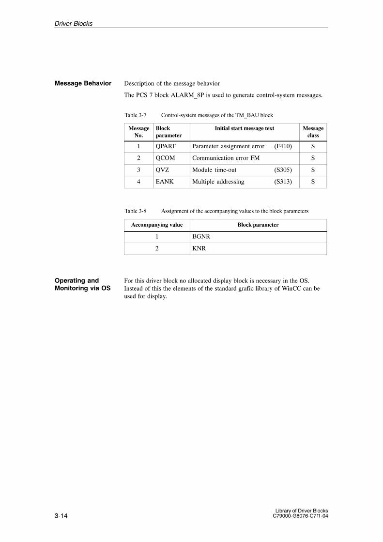
3-14Library of Driver Blocks
C79000-G8076-C711-04
Message Behavior Description of the message behavior
The PCS 7 block ALARM_8P is used to generate control-system messages.
Table 3-7 Control-system messages of the TM_BAU block
MessageNo.
Blockparameter
Initial start message text Messageclass
1 QPARF Parameter assignment error (F410) S
2 QCOM Communication error FM S
3 QVZ Module time-out (S305) S
4 EANK Multiple addressing (S313) S
Table 3-8 Assignment of the accompanying values to the block parameters
Accompanying value Block parameter
1 BGNR
2 KNR
For this driver block no allocated display block is necessary in the OS.Instead of this the elements of the standard grafic library of WinCC can beused for display.
Operating andMonitoring via OS
Driver Blocks

3-15Library of Driver BlocksC79000-G8076-C711-04
The following tables present the input and output bars of the block.
Table 3-9 Input bar
Element Meaning Type Initialvalue
Attr. O&M
Permittedvalues
I1 Binary output 1 BOOL 0 Q
⋅⋅⋅ ⋅⋅⋅
I32 Binary output 32 BOOL 0 Q
BGNR Module number INT –1 0...60, 100...160
BTYP Module type INT 0 0...3
EN_MSG Enable control system messages BOOL 0 Q
EV_ID Message number DWORD 0 U
Table 3-10 Output bar
Element Meaning Type Initialvalue
Attr. O&M
Permittedvalues
BGF Module fault (QCOM v QVZ v EANK)
BOOL 1
QPARF Parameter assignment error 1) BOOL 0
STATUS Block state WORD 0 U
QERR Inverted value of ENO BOOL 1 U
1) If QPARF = 1 no processing of the block is done.
I/O Bars
Driver Blocks
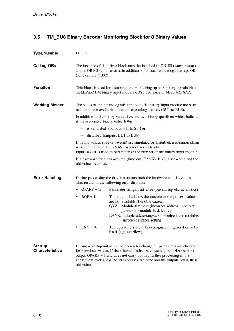
3-16Library of Driver Blocks
C79000-G8076-C711-04
3.5 TM_BU8 Binary Encoder Monitoring Block for 8 Binary Values
FB 305
The instance of the driver block must be installed in OB100 (warm restart)and in OB102 (cold restart), in addition to its usual watchdog interrupt OB(for example OB32).
This block is used for acquiring and monitoring up to 8 binary signals via aTELEPERM M binary input module 6DS1 620-8AA or 6DS1 621-8AA.
The states of the binary signals applied to the binary input module are scan-ned and made available at the corresponding outputs (BU1 to BU8).
In addition to the binary value there are two binary qualifiers which indicateif the associated binary value BWn
– is simulated (outputs: SI1 to SI8) or
– disturbed (outputs: BU1 to BU8).
If binary values (one or several) are simulated or disturbed, a common alarmis issued via the outputs SASI or SAST respectively.Input BGNR is used to parameterize the number of the binary input module.
If a hardware fault has occured (time-out, EANK), BGF is set = true and theold values retained.
During processing the driver monitors both the hardware and the values.This results in the following error displays:
� QPARF = 1: Parameter assignment error (see startup characteristics)
� BGF = 1: This output indicates the module or the process valuesare not available. Possible causes:QVZ: Module time-out (incorrect address, incorrect
jumpers or module is defective),EANK:multiple addressing/acknowledge from modules
(incorrect jumper setting)
� ENO = 0: The operating system has recognized a general error byitself (e.g. overflow).
During a startup/initial run or parameter change all parameters are checkedfor permitted values. If the allowed limits are exceeded, the driver sets itsoutput QPARF = 1 and does not carry out any further processing in thesubsequent cycles, e.g. no I/O accesses are done and the outputs retain theirold values.
Type/Number
Calling OBs
Function
Working Method
Error Handling
StartupCharacteristics
Driver Blocks

3-17Library of Driver BlocksC79000-G8076-C711-04
Time Response Does not exist. If the driver output values are needed from blocks with timeresponse (e.g. closed-loop control block) the driver has to be installed in thesame OB before this block.
Message Behavior Description of the message behavior.The PCS 7 block ALARM_8P is used to generate control-system messages.
Table 3-11 Control-system messages of the TM_BU8 block
MessageNo.
Blockparameter
Initial start message text Messageclass
1 QPARF Parameter assignment error (F410) S
2 QCOM Communication error FM S
3 QVZ Module time-out (S305) S
4 EANK Multiple addressing (S313) S
Table 3-12 Assignment of the accompanying values to the block parameters
Accompanying value Block parameter
1 BGNR
For this driver block no allocated display block is necessary in the OS.Instead of this the elements of the standard grafic library of WinCC can beused for display.
Operating andMonitoring via OS
Driver Blocks
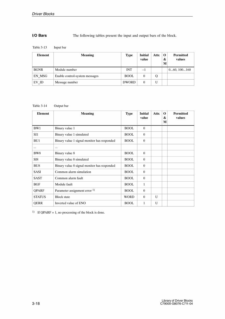
3-18Library of Driver Blocks
C79000-G8076-C711-04
The following tables present the input and output bars of the block.
Table 3-13 Input bar
Element Meaning Type Initialvalue
Attr. O&M
Permittedvalues
BGNR Module number INT –1 0...60, 100...160
EN_MSG Enable control-system messages BOOL 0 Q
EV_ID Message number DWORD 0 U
Table 3-14 Output bar
Element Meaning Type Initialvalue
Attr. O&M
Permittedvalues
BW1 Binary value 1 BOOL 0
SI1 Binary value 1 simulated BOOL 0
BU1 Binary value 1 signal monitor has responded BOOL 0
... ...
BW8 Binary value 8 BOOL 0
SI8 Binary value 8 simulated BOOL 0
BU8 Binary value 8 signal monitor has responded BOOL 0
SASI Common alarm simulation BOOL 0
SAST Common alarm fault BOOL 0
BGF Module fault BOOL 1
QPARF Parameter assignment error 1) BOOL 0
STATUS Block state WORD 0 U
QERR Inverted value of ENO BOOL 1 U
1) If QPARF = 1, no processing of the block is done.
I/O Bars
Driver Blocks

3-19Library of Driver BlocksC79000-G8076-C711-04
3.6 TM_BU16 Binary Encoder Monitoring Block for 16 Binary Values
FB 306
The instance of the driver block must be installed in OB100 (warm restart)and in OB102 (cold restart), in addition to its usual watchdog interrupt OB(for example OB32).
This block is used for acquiring and monitoring up to 16 binary signals via aTELEPERM M binary input module 6DS1 600-8AA/-8BA.
The states of the binary signals applied to the binary input module are scan-ned and made available at the corresponding outputs (BU1 to BU16).
In addition to the binary value there are two binary qualifiers which indicateif the associated binary value BWn is
– simulated (outputs: SI1 to SI16) or
– disturbed (outputs: BU1 to BU16).
If binary values (one or several) are simulated or disturbed, a common alarmis issued via the outputs SASI or SAST respectively.Input BGNR is used to parameterize the number of the binary input module.
If a hardware fault has occured (time-out, EANK), BGF is set = true and theold values retained.
During processing the driver monitors both the hardware and the value.This results in the following error displays:
� QPARF = 1: Parameter assignment error (see startup characteristics)
� BGF = 1: This output indicates the module or the process valuesare not available. Possible causes:QVZ: Module time-out (incorrect address, incorrect
jumpers or module is defective),EANK:multiple addressing/acknowledge from modules
(incorrect jumper setting)
� ENO = 0: The operating system has recognized a general error byitself (e.g. overflow).
During a startup/initial run or parameter change all parameters are checkedfor permitted values. If the allowed limits are exceeded, the driver sets itsoutput QPARF = 1 and does not carry out any further processing in thesubsequent cycles, e.g. no I/O accesses are done and the outputs retain theirold values.
Type/Number
Calling OBs
Function
Working Method
Error Handling
StartupCharacteristics
Driver Blocks

3-20Library of Driver Blocks
C79000-G8076-C711-04
Time Response Does not exist. If the driver output values are needed from blocks with timeresponse (e.g. closed-loop control block) the driver has to be installed in thesame OB before this block.
Message Behavior Description of the message behavior.The PCS 7 block ALARM_8P is used to generate control-system messages.
Table 3-15 Control-system messages of the TM_BU16 block
MessageNo.
Blockparameter
Initial start message text Messageclass
1 QPARF Parameter assignment error (F410) S
2 QCOM Communication error FM S
3 QVZ Module time-out (S305) S
4 EANK Multiple addressing (S313) S
Table 3-16 Assignment of the accompanying values to the block parameters
Accompanying value Block parameter
1 BGNR
For this driver block no allocated display block is necessary in the OS.Instead of this the elements of the standard grafic library of WinCC can beused for display.
Operating andMonitoring via OS
Driver Blocks
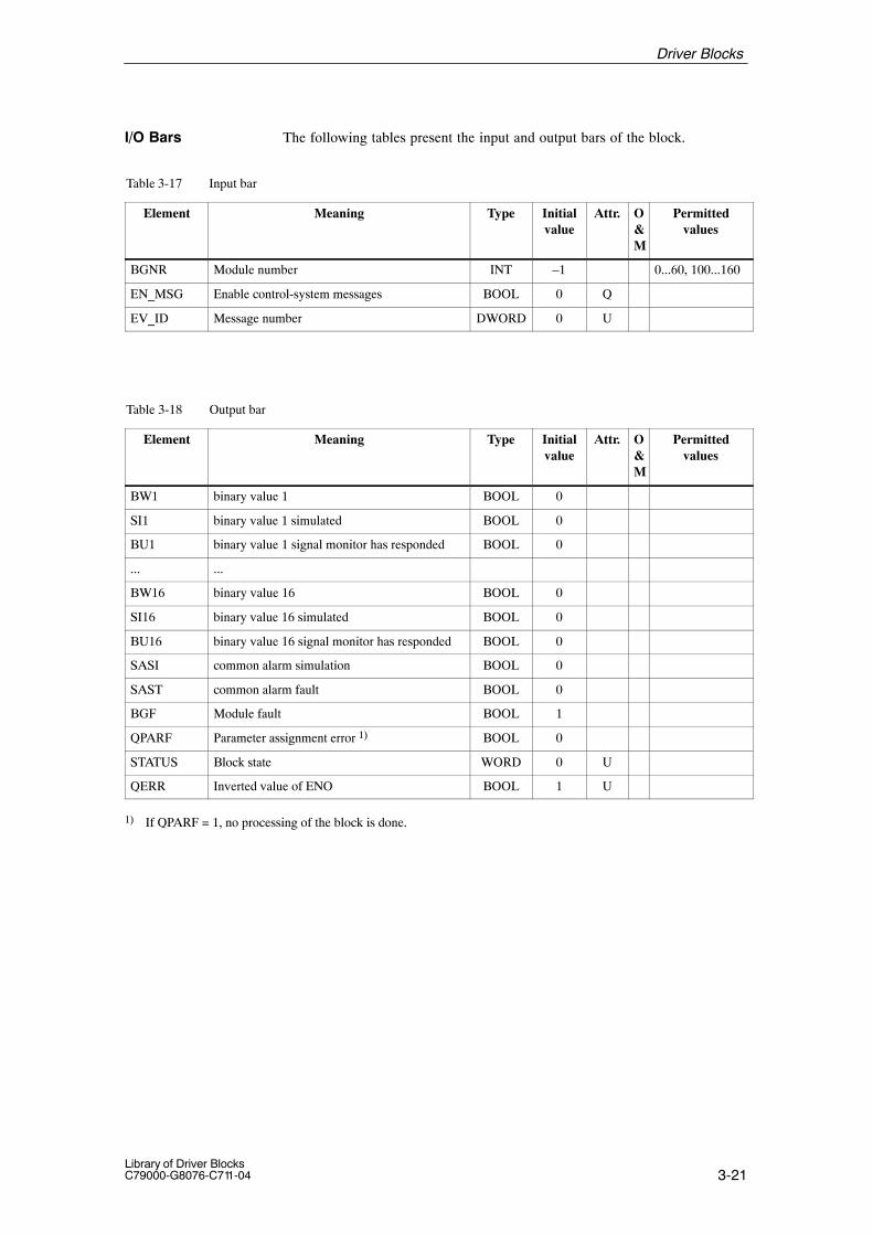
3-21Library of Driver BlocksC79000-G8076-C711-04
The following tables present the input and output bars of the block.
Table 3-17 Input bar
Element Meaning Type Initialvalue
Attr. O&M
Permittedvalues
BGNR Module number INT –1 0...60, 100...160
EN_MSG Enable control-system messages BOOL 0 Q
EV_ID Message number DWORD 0 U
Table 3-18 Output bar
Element Meaning Type Initialvalue
Attr. O&M
Permittedvalues
BW1 binary value 1 BOOL 0
SI1 binary value 1 simulated BOOL 0
BU1 binary value 1 signal monitor has responded BOOL 0
... ...
BW16 binary value 16 BOOL 0
SI16 binary value 16 simulated BOOL 0
BU16 binary value 16 signal monitor has responded BOOL 0
SASI common alarm simulation BOOL 0
SAST common alarm fault BOOL 0
BGF Module fault BOOL 1
QPARF Parameter assignment error 1) BOOL 0
STATUS Block state WORD 0 U
QERR Inverted value of ENO BOOL 1 U
1) If QPARF = 1, no processing of the block is done.
I/O Bars
Driver Blocks

3-22Library of Driver Blocks
C79000-G8076-C711-04
3.7 TM_AE Analog Input Block
FB 303
The instance of the driver block must be installed in OB100 (warm restart)and in OB102 (cold restart), in addition to its usual watchdog interrupt OB(for example OB32).
This block is used to measure an external analog signal via a channel of oneof the following TELEPERM M analog input modules:6DS1 700-8AA/-8BA, 6DS1 701-8AA/-8AB (NAMUR),6DS1 703-8AA/-8RR, 6DS1 713-8AB, 6DS1 730-8AA, 6DS1 731-8xx,or a SIMATIC S5 analog input module connected via one of the TELE-PERM M modules: 6DS1 321-8AA or 6DS1 327-8AA.
The block converts a normalized input signal from an analog input moduleinto an analog value of internal floating point representation.
The output value is made available at output 1 (X) as a physical quantity wit-hin the parameterized range (XA, XE). If the analog value is outside thisrange, a message is sent to output 2 (XF). Output 3 (BGF) is used to signal amalfunction of the associated analog input module.
If a fault indication occurs during measurement, the old value of X is retai-ned. A faulty input signal (overrange, open-circuit) initiates output XF = 1and the error number S320, a faulty channel initiates output of the error num-ber S321. “BGF” is set and the error number S305 issued if the module isdefective.
Analog values from SIMATIC modules are monitored for violation of limitvalues. Permissible values are 3 to 22 mA for unipolar signals and –55 to+55 mA for bipolar signals. The fault indication XF is only set if the measu-red value is higher or lower than these limits. The last permissible value isthen indicated.
The module number (input 3) and the number of the channel on the module(input 4) are parameterized separately.
If either of the parameters BGNR or KNR is changed, the effects on the sub-sequent process section must be taken into account.
� Parameterization:
(1st analog value): KNR = 0 or 32 or KNR = 100 or KNR = 200
KNR = 0 – 31 : TELEPERM M-standard 6DS1700,6DS1731KNR = 32 – 63 : TELEPERM M-standard 6DS1701 with NAMUR
limits; Even in case of overflow the actual value ofthe module is indicated at output X.
KNR = 100 – 131: SIMATIC S5 0 ... 20 mA or –50 ... +50 mASIMATIC module must transfer 2’th complement.
KNR = 200 – 231: SIMATIC S5 4 ... 20 mA (live zero)
Type/Number
Calling OBs
Function
Working Method
Driver Blocks
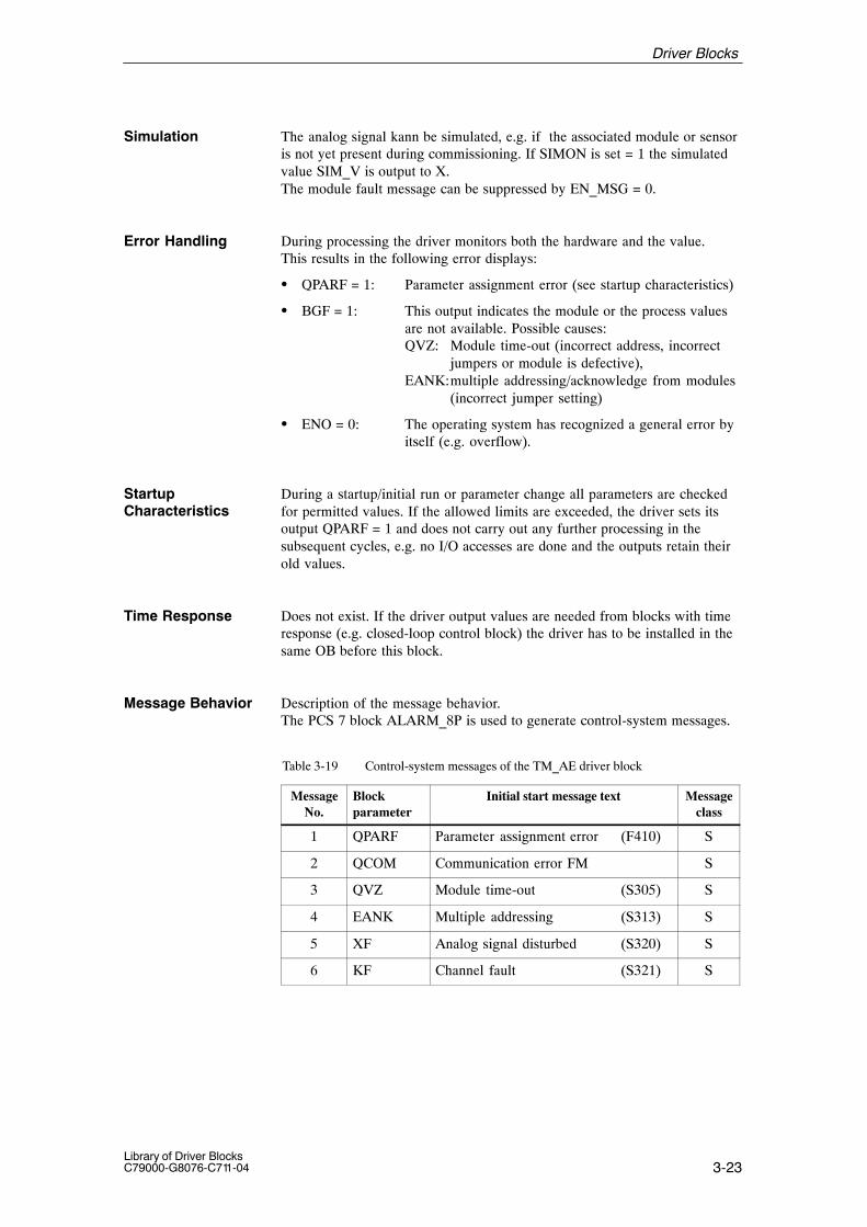
3-23Library of Driver BlocksC79000-G8076-C711-04
The analog signal kann be simulated, e.g. if the associated module or sensoris not yet present during commissioning. If SIMON is set = 1 the simulatedvalue SIM_V is output to X.The module fault message can be suppressed by EN_MSG = 0.
During processing the driver monitors both the hardware and the value.This results in the following error displays:
� QPARF = 1: Parameter assignment error (see startup characteristics)
� BGF = 1: This output indicates the module or the process valuesare not available. Possible causes:QVZ: Module time-out (incorrect address, incorrect
jumpers or module is defective),EANK:multiple addressing/acknowledge from modules
(incorrect jumper setting)
� ENO = 0: The operating system has recognized a general error byitself (e.g. overflow).
During a startup/initial run or parameter change all parameters are checkedfor permitted values. If the allowed limits are exceeded, the driver sets itsoutput QPARF = 1 and does not carry out any further processing in thesubsequent cycles, e.g. no I/O accesses are done and the outputs retain theirold values.
Time Response Does not exist. If the driver output values are needed from blocks with timeresponse (e.g. closed-loop control block) the driver has to be installed in thesame OB before this block.
Message Behavior Description of the message behavior.The PCS 7 block ALARM_8P is used to generate control-system messages.
Table 3-19 Control-system messages of the TM_AE driver block
MessageNo.
Blockparameter
Initial start message text Messageclass
1 QPARF Parameter assignment error (F410) S
2 QCOM Communication error FM S
3 QVZ Module time-out (S305) S
4 EANK Multiple addressing (S313) S
5 XF Analog signal disturbed (S320) S
6 KF Channel fault (S321) S
Simulation
Error Handling
StartupCharacteristics
Driver Blocks

3-24Library of Driver Blocks
C79000-G8076-C711-04
Table 3-20 Assignment of the accompanying values to the block parameters
Accompanying value Block parameter
1 BGNR
2 KNR
For this driver block no allocated display block is necessary in the OS.Instead of this the elements of the standard grafic library of WinCC can beused for display.
The following tables present the input and output bars of the block.
Table 3-21 Input bar
Element Meaning Type Initialvalue
Attr. O&M
Permittedvalues
XE Upper range limit REAL 100,0 Q
XA Lower range limit REAL 0,0 Q
SIMON Simulation ON BOOL 0 Q
SIM_V Simulation value REAL 0,0 Q
BGNR Module number INT –1 0...60, 100...160
KNR Channel number on module (with mode) INT 0 0...31,32...63,100...131,200...231
EN_MSG Enable control system messages BOOL 0 Q
EV_ID Message number DWORD 0 U
Table 3-22 Output bar
Element Meaning Type Initialvalue
Attr. O&M
Permittedvalues
X Analog value REAL 0,0
XF Analog signal disturbed 1) BOOL 1
BGF Module defective (QCOM v QVZ v EANK v KF)
BOOL 1
QPARF Parameter assignment error 2) BOOL 0
STATUS Block state WORD 0 U
QERR Inverted value of ENO BOOL 1 U
1) XF = 0 if SIMON = 12) If QPARF = 1 no processing of the block is done.
Operating andMonitoring via OS
I/O Bars
Driver Blocks

3-25Library of Driver BlocksC79000-G8076-C711-04
3.8 TM_AA Analog Output Block
FB 304
The instance of the driver block must be installed in OB100 (warm restart)and in OB102 (cold restart), in addition to its usual watchdog interrupt OB(for example OB32).
This block is used to output an analog signal via a channel of one of the fol-lowing TELEPERM M analog output modules: 6DS1 702-8AA,6DS1702-8RRor a SIMATIC S5 analog output module connected via one of the TM modu-les: 6DS1 321-8AA oder 6DS1 327-8AA.
This block converts an analog value from the internal floating point represen-tation into an output signal which is adapted to the respective TELEPERM Mor S5 analog output module. The analog value entered via input (X) is firstnormalized and limited according to the measuring range (XA, XE). Then itis fed to a channel of an analog output module which has been parameterizedvia BGNR (module number) and KNR (channel number).
Always use the numbers 0 to 31 to select and address the channels of all TELEPERM M modules. If numbers between 100 and 131 or 200 and 231are used the program will be set to SIMATIC modules which will then beaddressed with channel numbers between 0 and 31 (without offset 100 or200).
� Parameterization:
channel number 0 ... 31 TELEPERM M-Standardchannel number 100 ... 131 SIMATIC S5-bipolarchannel number 200 ... 231 SIMATIC S5-unipolar (4 ... 20 mA)
During processing the driver monitors both the hardware and the value.This results in the following error displays:
� QPARF = 1: Parameter assignment error (see startup characteristics)
� BGF = 1: This output indicates the module or the process valuesare not available. Possible causes:QVZ: Module time-out (incorrect address, incorrect
jumpers or module is defective),EANK:multiple addressing/acknowledge from modules
(incorrect jumper setting)
� ENO = 0: The operating system has recognized a general error byitself (e.g. overflow).
Type/Number
Calling OBs
Function
Working Method
Error Handling
Driver Blocks
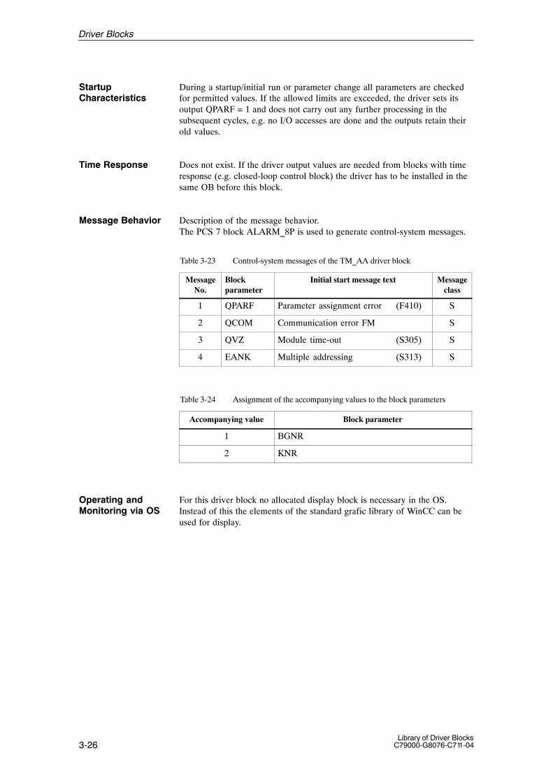
3-26Library of Driver Blocks
C79000-G8076-C711-04
During a startup/initial run or parameter change all parameters are checkedfor permitted values. If the allowed limits are exceeded, the driver sets itsoutput QPARF = 1 and does not carry out any further processing in thesubsequent cycles, e.g. no I/O accesses are done and the outputs retain theirold values.
Time Response Does not exist. If the driver output values are needed from blocks with timeresponse (e.g. closed-loop control block) the driver has to be installed in thesame OB before this block.
Message Behavior Description of the message behavior.The PCS 7 block ALARM_8P is used to generate control-system messages.
Table 3-23 Control-system messages of the TM_AA driver block
MessageNo.
Blockparameter
Initial start message text Messageclass
1 QPARF Parameter assignment error (F410) S
2 QCOM Communication error FM S
3 QVZ Module time-out (S305) S
4 EANK Multiple addressing (S313) S
Table 3-24 Assignment of the accompanying values to the block parameters
Accompanying value Block parameter
1 BGNR
2 KNR
For this driver block no allocated display block is necessary in the OS.Instead of this the elements of the standard grafic library of WinCC can beused for display.
StartupCharacteristics
Operating andMonitoring via OS
Driver Blocks
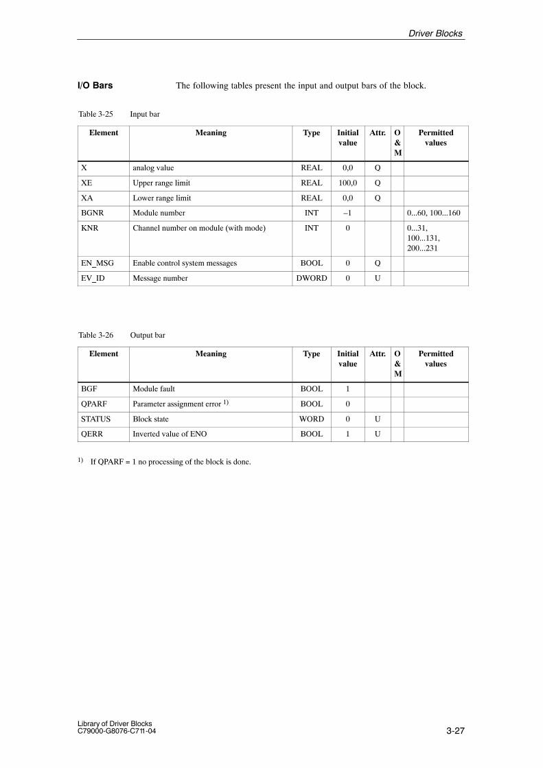
3-27Library of Driver BlocksC79000-G8076-C711-04
The following tables present the input and output bars of the block.
Table 3-25 Input bar
Element Meaning Type Initialvalue
Attr. O&M
Permittedvalues
X analog value REAL 0,0 Q
XE Upper range limit REAL 100,0 Q
XA Lower range limit REAL 0,0 Q
BGNR Module number INT –1 0...60, 100...160
KNR Channel number on module (with mode) INT 0 0...31,100...131,200...231
EN_MSG Enable control system messages BOOL 0 Q
EV_ID Message number DWORD 0 U
Table 3-26 Output bar
Element Meaning Type Initialvalue
Attr. O&M
Permittedvalues
BGF Module fault BOOL 1
QPARF Parameter assignment error 1) BOOL 0
STATUS Block state WORD 0 U
QERR Inverted value of ENO BOOL 1 U
1) If QPARF = 1 no processing of the block is done.
I/O Bars
Driver Blocks
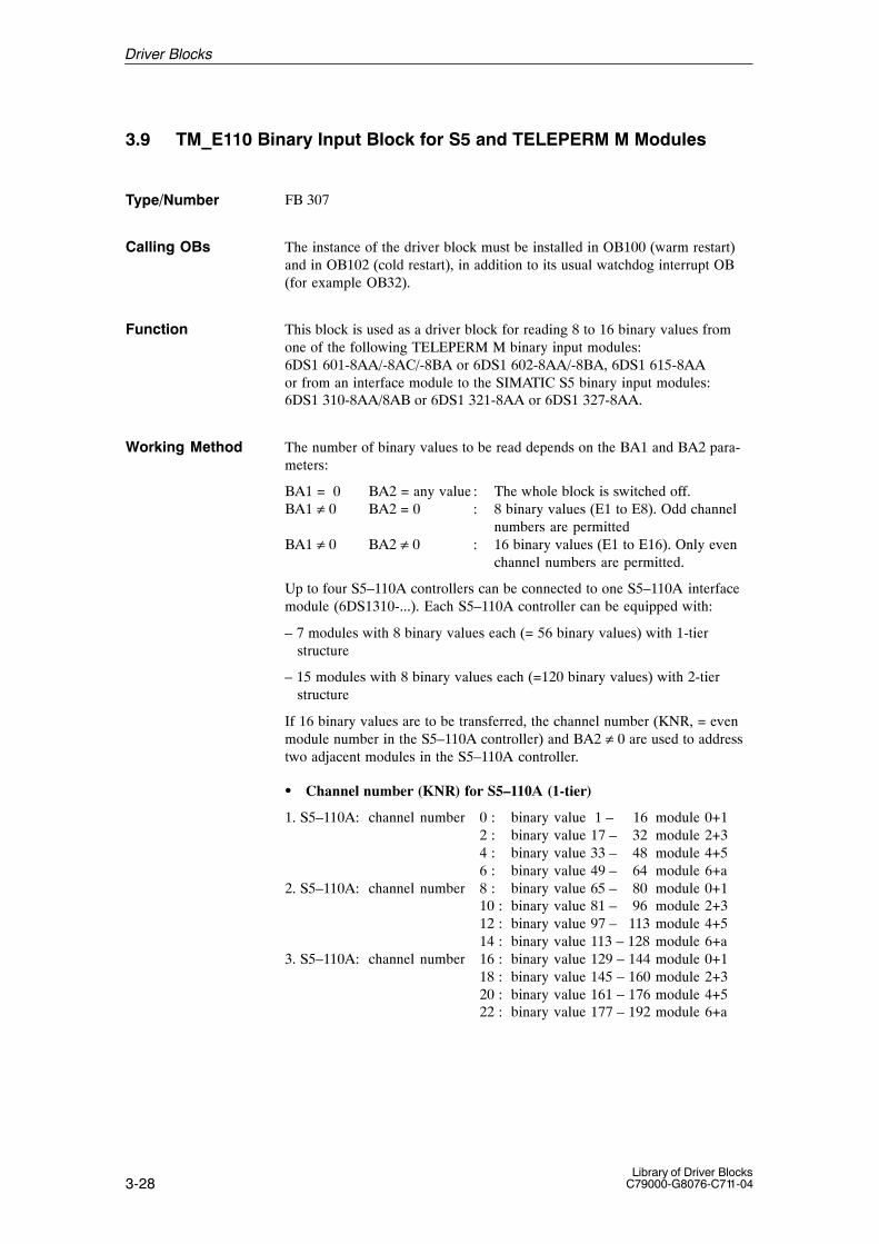
3-28Library of Driver Blocks
C79000-G8076-C711-04
3.9 TM_E110 Binary Input Block for S5 and TELEPERM M Modules
FB 307
The instance of the driver block must be installed in OB100 (warm restart)and in OB102 (cold restart), in addition to its usual watchdog interrupt OB(for example OB32).
This block is used as a driver block for reading 8 to 16 binary values fromone of the following TELEPERM M binary input modules:6DS1 601-8AA/-8AC/-8BA or 6DS1 602-8AA/-8BA, 6DS1 615-8AAor from an interface module to the SIMATIC S5 binary input modules:6DS1 310-8AA/8AB or 6DS1 321-8AA or 6DS1 327-8AA.
The number of binary values to be read depends on the BA1 and BA2 para-meters:
BA1 = 0 BA2 = any value : The whole block is switched off.BA1 ≠ 0 BA2 = 0 : 8 binary values (E1 to E8). Odd channel
numbers are permittedBA1 ≠ 0 BA2 ≠ 0 : 16 binary values (E1 to E16). Only even
channel numbers are permitted.
Up to four S5–110A controllers can be connected to one S5–110A interfacemodule (6DS1310-...). Each S5–110A controller can be equipped with:
– 7 modules with 8 binary values each (= 56 binary values) with 1-tier structure
– 15 modules with 8 binary values each (=120 binary values) with 2-tier structure
If 16 binary values are to be transferred, the channel number (KNR, = evenmodule number in the S5–110A controller) and BA2 ≠ 0 are used to addresstwo adjacent modules in the S5–110A controller.
� Channel number (KNR) for S5–110A (1-tier)
1. S5–110A: channel number 0 : binary value 1 – 16 module 0+12 : binary value 17 – 32 module 2+34 : binary value 33 – 48 module 4+56 : binary value 49 – 64 module 6+a
2. S5–110A: channel number 8 : binary value 65 – 80 module 0+110 : binary value 81 – 96 module 2+312 : binary value 97 – 113 module 4+514 : binary value 113 – 128 module 6+a
3. S5–110A: channel number 16 : binary value 129 – 144 module 0+118 : binary value 145 – 160 module 2+320 : binary value 161 – 176 module 4+522 : binary value 177 – 192 module 6+a
Type/Number
Calling OBs
Function
Working Method
Driver Blocks

3-29Library of Driver BlocksC79000-G8076-C711-04
4. S5–110A: channel number 24 : binary value 193 – 208 module 0+126 : binary value 209 – 224 module 2+328 : binary value 225 – 240 module 4+530 : binary value 242 – 256 module 6+a
a = flags
The last eight binary values of each S5–110A contain flags and may not beinterconnected with a module.
� Channel number (KNR) for S5–110A (2-tier)
1. S5–110A: channel number 0 : binary value 1 – 16 module 0+ 12 : binary value 17 – 32 module 2+ 34 : binary value 33 – 48 module 4+ 56 : binary value 49 – 64 module 6+ 78 : binary value 65 – 80 module 8+ 910 : binary value 81 – 96 module 10+1112 : binary value 97 – 113 module 12+1314 : binary value 113 – 128 module 14+a
2. S5–110A: channel number 16 : binary value 129 – 144 module 0+ 1 18 : binary value 145 – 160 module 2+ 320 : binary value 161 – 176 module 4+ 522 : binary value 177 – 192 module 6+ 7 24 : binary value 193 – 208 module 8+ 926 : binary value 209 – 224 module 10+1128 : binary value 225 – 240 module 12+1330 : binary value 242 – 256 module 14+a
3. S5–110A: channel number 32 : binary value 257 – 275 module 0+ 134 : binary value 276 – 291 module 2+ 3
etc. to
4. S5–110A: channel number 62 : binary value 496 – 512 module 14+ a
The last eight binary values of each S5–110A contain flags and may not beinterconnected with a module.
� Flag assignments
Binary value E9 = Incorrect number of lines (jumper)E10 = Rapid shutdown, since cyclic monitoring has
failed (binary outputs reset)E11 = Message frame faultE12 = No time specifiedE13 = Module faultE14 = not applicableE15 = not applicableE16 = not applicable
The number of bytes read and the associated channel address depend on theparameters BA1, BA2, and KNR.
Driver Blocks

3-30Library of Driver Blocks
C79000-G8076-C711-04
BA1 = 0 , BA2 any value : Whole block de-activatedBA1 ≠ 0 , BA2 = 0 : 1 byte from address = KNR is transferred to the
first group. KNR may be even or odd.BA1 ≠ 0 , BA2 ≠ 0 : 2 bytes are read from the addresses KNR and
KNR + 1, if KNR is even. If KNR is odd, the next smaller even address isused instead of KNR.
Old and new value of each group (E1 - E8, E9 – E16) are compared witheach other. New values are only stored if there is a difference in these values.Output BGF will be set if the module number has been set incorrectly on themodule or in the TM_E110 (etc.) or if several modules use the same modulenumber. Then the old binary values are retained.
� Parameter Description
BA1 : = 0; block disabled (no processing): = 1; E1 to E8 enabled: = 2; E1 to E8 enabled
E1 : binary value 1E2 : binary value 2E3 : binary value 3E4 : binary value 4E5 : binary value 5E6 : binary value 6E7 : binary value 7E8 : binary value 8BA2 : = 0; 2nd group OFF
: = 1; E9 to E16 activated (if BA1 nonzero): = 2; E9 to E16 activated (if BA1 nonzero)
E9 : binary value 9E10 : binary value 10E11 : binary value 11E12 : binary value 12E13 : binary value 13E14 : binary value 14E15 : binary value 15E16 : binary value 16
The modes BAx = 1 and 2 are identical (compatible with TELEPERM M).
During processing the driver monitors both the hardware and the values.This results in the following error displays:
� QPARF = 1: Parameter assignment error (see startup characteristics)
� BGF = 1: This output indicates the module or the process valuesare not available. Possible causes:QVZ: Module time-out (incorrect address, incorrect
jumpers or module is defective),EANK:multiple addressing/acknowledge from modules
(incorrect jumper setting)
� ENO = 0: The operating system has recognized a general error byitself (e.g. overflow).
Error Handling
Driver Blocks
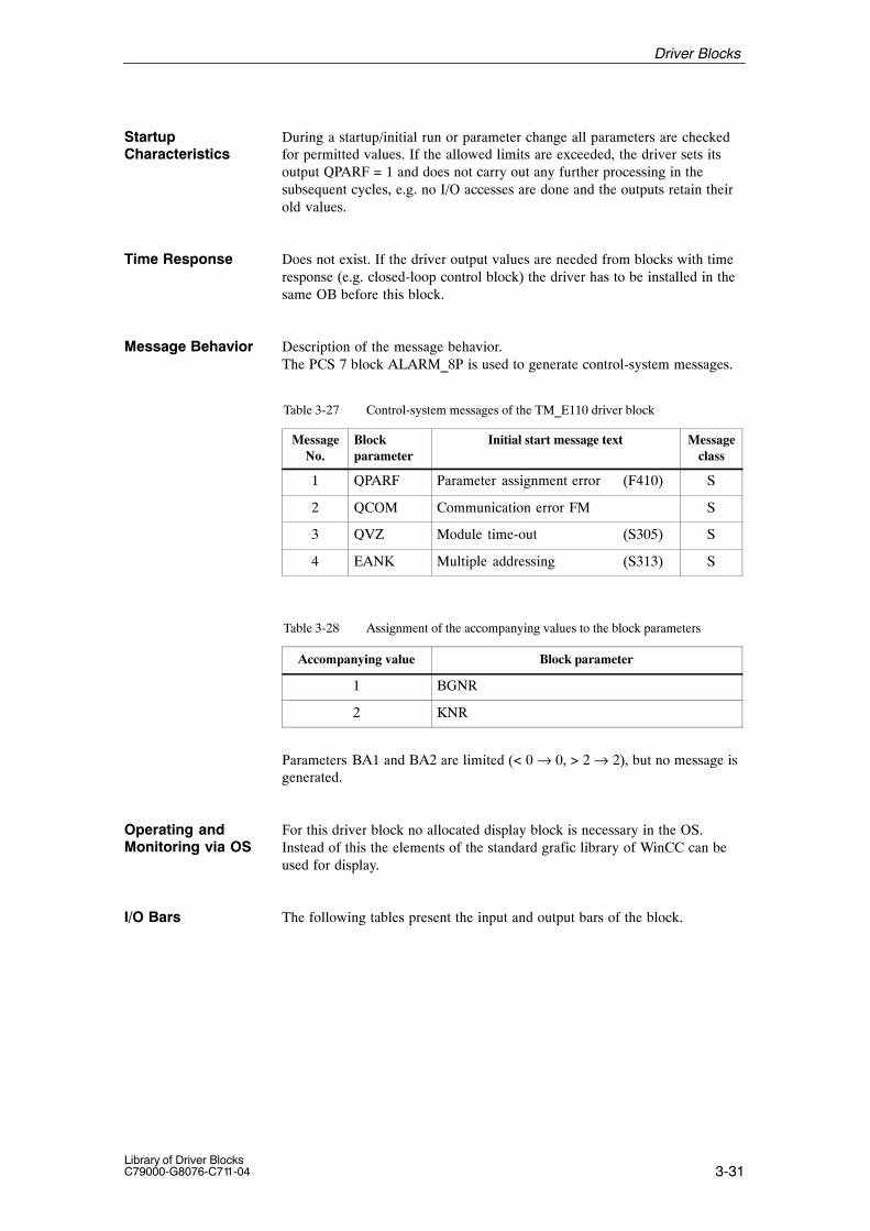
3-31Library of Driver BlocksC79000-G8076-C711-04
During a startup/initial run or parameter change all parameters are checkedfor permitted values. If the allowed limits are exceeded, the driver sets itsoutput QPARF = 1 and does not carry out any further processing in thesubsequent cycles, e.g. no I/O accesses are done and the outputs retain theirold values.
Time Response Does not exist. If the driver output values are needed from blocks with timeresponse (e.g. closed-loop control block) the driver has to be installed in thesame OB before this block.
Message Behavior Description of the message behavior.The PCS 7 block ALARM_8P is used to generate control-system messages.
Table 3-27 Control-system messages of the TM_E110 driver block
MessageNo.
Blockparameter
Initial start message text Messageclass
1 QPARF Parameter assignment error (F410) S
2 QCOM Communication error FM S
3 QVZ Module time-out (S305) S
4 EANK Multiple addressing (S313) S
Table 3-28 Assignment of the accompanying values to the block parameters
Accompanying value Block parameter
1 BGNR
2 KNR
Parameters BA1 and BA2 are limited (< 0 → 0, > 2 → 2), but no message isgenerated.
For this driver block no allocated display block is necessary in the OS.Instead of this the elements of the standard grafic library of WinCC can beused for display.
The following tables present the input and output bars of the block.
StartupCharacteristics
Operating andMonitoring via OS
I/O Bars
Driver Blocks
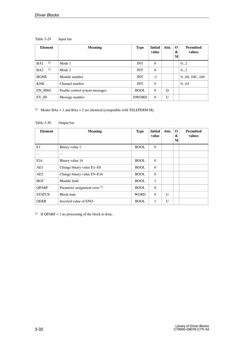
3-32Library of Driver Blocks
C79000-G8076-C711-04
Table 3-29 Input bar
Element Meaning Type Initialvalue
Attr. O&M
Permittedvalues
BA1 1) Mode 1 INT 0 0...2
BA2 1) Mode 2 INT 0 0...2
BGNR Module number INT –1 0...60, 100...160
KNR Channel number INT 0 0...63
EN_MSG Enable control system messages BOOL 0 Q
EV_ID Message number DWORD 0 U
1) Modes BAx = 1 and BAx = 2 are identical (compatible with TELEPERM M).
Table 3-30 Output bar
Element Meaning Type Initialvalue
Attr. O&M
Permittedvalues
E1 Binary value 1 BOOL 0
⋅⋅⋅ ⋅⋅⋅
E16 Binary value 16 BOOL 0
AE1 Change binary value E1–E8 BOOL 0
AE2 Change binary value E9–E16 BOOL 0
BGF Module fault BOOL 1
QPARF Parameter assignment error 1) BOOL 0
STATUS Block state WORD 0 U
QERR Inverted value of ENO BOOL 1 U
1) If QPARF = 1 no processing of the block is done.
Driver Blocks
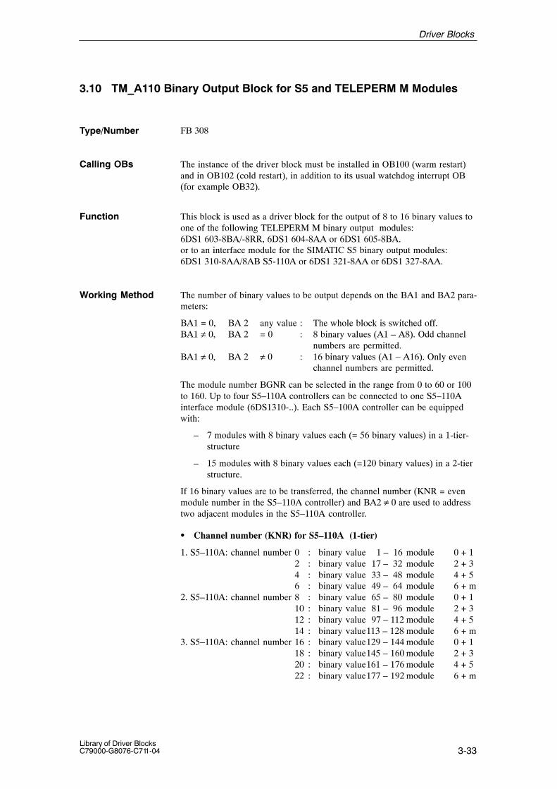
3-33Library of Driver BlocksC79000-G8076-C711-04
3.10 TM_A110 Binary Output Block for S5 and TELEPERM M Modules
FB 308
The instance of the driver block must be installed in OB100 (warm restart)and in OB102 (cold restart), in addition to its usual watchdog interrupt OB(for example OB32).
This block is used as a driver block for the output of 8 to 16 binary values toone of the following TELEPERM M binary output modules:6DS1 603-8BA/-8RR, 6DS1 604-8AA or 6DS1 605-8BA.or to an interface module for the SIMATIC S5 binary output modules:6DS1 310-8AA/8AB S5-110A or 6DS1 321-8AA or 6DS1 327-8AA.
The number of binary values to be output depends on the BA1 and BA2 para-meters:
BA1 = 0, BA 2 any value : The whole block is switched off.BA1 ≠ 0, BA 2 = 0 : 8 binary values (A1 – A8). Odd channel
numbers are permitted.BA1 ≠ 0, BA 2 ≠ 0 : 16 binary values (A1 – A16). Only even
channel numbers are permitted.
The module number BGNR can be selected in the range from 0 to 60 or 100to 160. Up to four S5–110A controllers can be connected to one S5–110Ainterface module (6DS1310-..). Each S5–100A controller can be equippedwith:
– 7 modules with 8 binary values each (= 56 binary values) in a 1-tier-structure
– 15 modules with 8 binary values each (=120 binary values) in a 2-tierstructure.
If 16 binary values are to be transferred, the channel number (KNR = evenmodule number in the S5–110A controller) and BA2 ≠ 0 are used to addresstwo adjacent modules in the S5–110A controller.
� Channel number (KNR) for S5–110A (1-tier)
1. S5–110A: channel number 0 : binary value 1 – 16 module 0 + 12 : binary value 17 – 32 module 2 + 34 : binary value 33 – 48 module 4 + 56 : binary value 49 – 64 module 6 + m
2. S5–110A: channel number 8 : binary value 65 – 80 module 0 + 110 : binary value 81 – 96 module 2 + 312 : binary value 97 – 112 module 4 + 514 : binary value113 – 128 module 6 + m
3. S5–110A: channel number 16 : binary value129 – 144 module 0 + 118 : binary value145 – 160 module 2 + 320 : binary value161 – 176 module 4 + 522 : binary value177 – 192 module 6 + m
Type/Number
Calling OBs
Function
Working Method
Driver Blocks
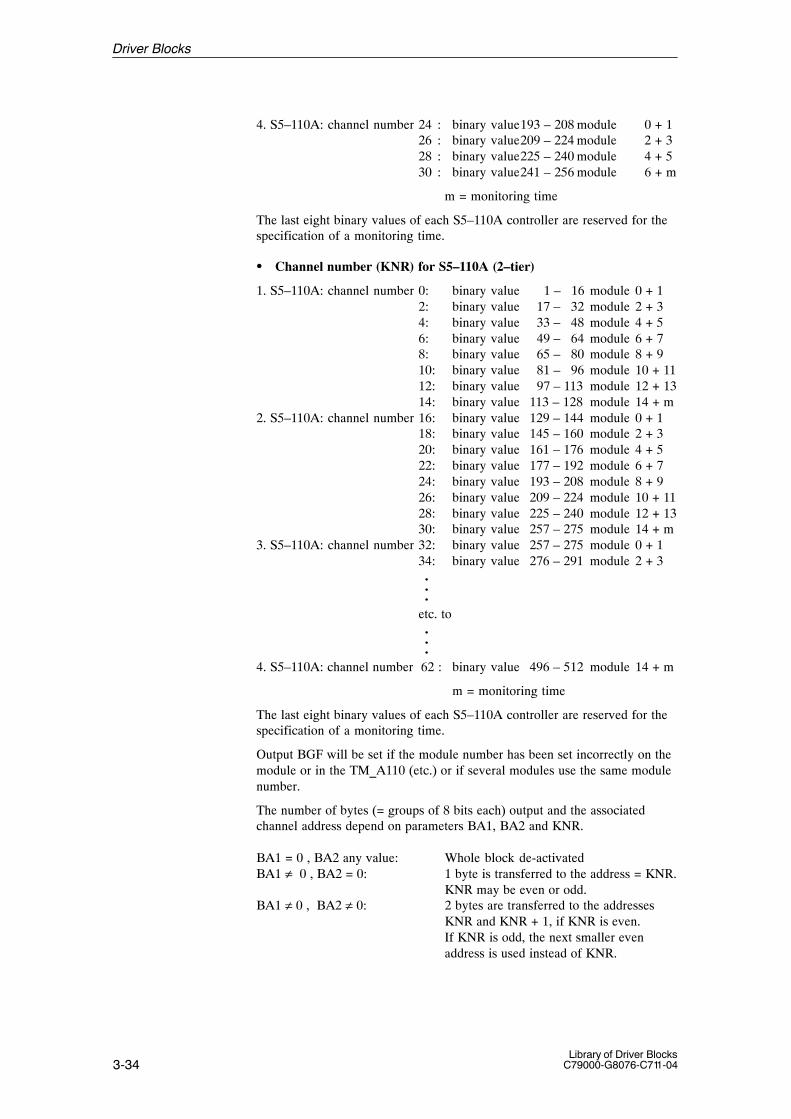
3-34Library of Driver Blocks
C79000-G8076-C711-04
4. S5–110A: channel number 24 : binary value193 – 208 module 0 + 126 : binary value209 – 224 module 2 + 328 : binary value225 – 240 module 4 + 530 : binary value241 – 256 module 6 + m
m = monitoring time
The last eight binary values of each S5–110A controller are reserved for thespecification of a monitoring time.
� Channel number (KNR) for S5–110A (2–tier)
1. S5–110A: channel number 0: binary value 1 – 16 module 0 + 12: binary value 17 – 32 module 2 + 34: binary value 33 – 48 module 4 + 56: binary value 49 – 64 module 6 + 78: binary value 65 – 80 module 8 + 910: binary value 81 – 96 module 10 + 1112: binary value 97 – 113 module 12 + 1314: binary value 113 – 128 module 14 + m
2. S5–110A: channel number 16: binary value 129 – 144 module 0 + 118: binary value 145 – 160 module 2 + 320: binary value 161 – 176 module 4 + 522: binary value 177 – 192 module 6 + 724: binary value 193 – 208 module 8 + 926: binary value 209 – 224 module 10 + 1128: binary value 225 – 240 module 12 + 1330: binary value 257 – 275 module 14 + m
3. S5–110A: channel number 32: binary value 257 – 275 module 0 + 134: binary value 276 – 291 module 2 + 3...
etc. to ...
4. S5–110A: channel number 62 : binary value 496 – 512 module 14 + m
m = monitoring time
The last eight binary values of each S5–110A controller are reserved for thespecification of a monitoring time.
Output BGF will be set if the module number has been set incorrectly on themodule or in the TM_A110 (etc.) or if several modules use the same modulenumber.
The number of bytes (= groups of 8 bits each) output and the associatedchannel address depend on parameters BA1, BA2 and KNR.
BA1 = 0 , BA2 any value: Whole block de-activatedBA1 ≠ 0 , BA2 = 0: 1 byte is transferred to the address = KNR.
KNR may be even or odd.BA1 ≠ 0 , BA2 ≠ 0: 2 bytes are transferred to the addresses
KNR and KNR + 1, if KNR is even. If KNR is odd, the next smaller even address is used instead of KNR.
Driver Blocks

3-35Library of Driver BlocksC79000-G8076-C711-04
� Parameter Description
BA1 : = 0; block disabled (no processing): = 1; 1st group (A1 to A8) enabled: = 2; 1st group (A1 to A8) enabled
A1 : binary value 1A2 : binary value 2A3 : binary value 3A4 : binary value 4A5 : binary value 5A6 : binary value 6A7 : binary value 7A8 : binary value 8
BA2 : = 0; 2nd group OFF: = 1; A9 to A16 activated (if BA1 nonzero): = 2; A9 to A16 activated (if BA1 nonzero): = 3; specification monitoring time (if BA1 nonzero)
A9 : binary value 9A10 : binary value 10A11 : binary value 11A12 : binary value 12A13 : binary value 13A14 : binary value 14A15 : binary value 15A16 : binary value 16
The modes BAx = 1 and 2 are identical (compatible with TELEPERM M).
During processing the driver monitors both the hardware and the value.This results in the following error displays:
� QPARF = 1: Parameter assignment error (see startup characteristics)
� BGF = 1: This output indicates the module or the process valuesare not available. Possible causes:QVZ: Module time-out (incorrect address, incorrect
jumpers or module is defective),EANK:multiple addressing/acknowledge from modules
(incorrect jumper setting)
� ENO = 0: The operating system has recognized a general error byitself (e.g. overflow).
During a startup/initial run or parameter change all parameters are checkedfor permitted values. If the allowed limits are exceeded, the driver sets itsoutput QPARF = 1 and does not carry out any further processing in thesubsequent cycles, e.g. no I/O accesses are done and the outputs retain theirold values.
Time Response Does not exist. If the driver output values are needed from blocks with timeresponse (e.g. closed-loop control block) the driver has to be installed in thesame OB before this block.
Error Handling
StartupCharacteristics
Driver Blocks
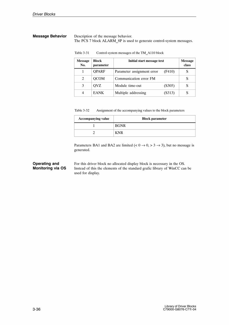
3-36Library of Driver Blocks
C79000-G8076-C711-04
Message Behavior Description of the message behavior.The PCS 7 block ALARM_8P is used to generate control-system messages.
Table 3-31 Control-system messages of the TM_A110 block
MessageNo.
Blockparameter
Initial start message text Messageclass
1 QPARF Parameter assignment error (F410) S
2 QCOM Communication error FM S
3 QVZ Module time-out (S305) S
4 EANK Multiple addressing (S313) S
Table 3-32 Assignment of the accompanying values to the block parameters
Accompanying value Block parameter
1 BGNR
2 KNR
Parameters BA1 and BA2 are limited (< 0 → 0, > 3 → 3), but no message isgenerated.
For this driver block no allocated display block is necessary in the OS.Instead of this the elements of the standard grafic library of WinCC can beused for display.
Operating andMonitoring via OS
Driver Blocks

3-37Library of Driver BlocksC79000-G8076-C711-04
The following tables present the input and output bars of the block.
Table 3-33 Input bar
Element Meaning Type Initialvalue
Attr. O&M
Permittedvalues
A1 Binary value 1 BOOL 0 Q
⋅⋅⋅ ⋅⋅⋅
A16 Binary value 16 BOOL 0 Q
BA1 1) Mode 1 INT 0 0...2
BA2 1) Mode 2 INT 0 0...3
BGNR Module number INT –1 0...60, 100...160
KNR Channel number INT 0 0...63
EN_MSG Enable control system messages BOOL 0 Q
EV_ID Message number DWORD 0 U
1) Modes BAx = 1 and BAx = 2 are identical (compatible with TELEPERM M)..
Table 3-34 Output bar
Element Meaning Type Initialvalue
Attr. O&M
Permittedvalues
BGF Module fault BOOL 1
QPARF Parameter assignment error 1) BOOL 0
STATUS Block state WORD 0 U
QERR Inverted value of ENO BOOL 1 U
1) If QPARF = 1 no processing of the block is done.
I/O Bars
Driver Blocks
3-38Library of Driver Blocks
C79000-G8076-C711-04
3.11 TM_DZ Driver Block for Proportioning Counter Module (2/4 Channels)
FB 309
The instance of the driver block must be installed in OB100 (warm restart)and in OB102 (cold restart), in addition to its usual watchdog interrupt OB(for example OB32).
This block is used for acquiring signals from the TELEPERM M proportio-ning counter module (2/4 channels) 6DS1 613-8.. and for sending commandsand normalized analog values to the proportioning counter module.
The proportioning counter module transfers various groups of binary and ana-log signals to the TM_DZ block. Here they are activated as output signals:
– Fault alarms (S4, S10, S16)
– Return data mode, interlocking (EXIN, VER)
– Configuration jumpers (DZDR, AVZ, TYP)
– Alarm signals, states (ESA, VSA, ZL)
– Analog values (X, ZSPW)
The following groups of binary and analog signals from the TM_DZ blockare transferred to the proportional counter module:
– Analog counter parameters (EW, VW, KF, TM)
– Binary counter parameters (VR, OGUG)
– Operator input commands (ZS, ZR, SP, FR)
� Modes
Monitoring and control of the proportioning counter module by the CPU areenabled if mode “External”, EXIN = 0 (corresponds to the hardware signalFEI = 0) has been selected. The operator input command “Set counter” (ZS = 1) is used to transfer the analog values EW, VW, KF, TM and the bi-nary values OGUG, VR to the proportioning counter module.
Im manual mode (HDAC = 0) the final value EW can be specified by the OSwithin the programmable range limits (XA1 and XE1). The intermediate va-lue VW can also be modified within the programmable control limits (XA2and XE2).
In automatic mode (HDAC = 1) ZS = 1 interconnects the inputs EWAC andVWAC with the proportioning counter module. New count parameters (EW,VW, KF, TM) may only be entered after the current count operation has com-pleted, i.e. after the return message ES = 1 has been set by the module.
Type/Number
Calling OBs
Function
Working Method
Driver Blocks
3-39Library of Driver BlocksC79000-G8076-C711-04
� Effects of the operator input commands (ZS, ZR, SP, FR)
– ZS = 1: Acceptance of the counter parameters transferred by the TM_DZ block and start of counting. Return data: counter active (ZL = 1).
– ZR = 1: Counting is interrupted; (the counter content (X) will be set to the appropriate start value with next start of counter). A counter inhibit is released. Depending on the ANL confi-guration jumper, the signal “Final value attained” is set(ES = 1).
– SP = 1: The counter output is disabled, the signal “Final value attained” is set. (ES = 1). The counter continues running(X-display) and counts a possible overshoot.
– FR = 1: If the counter is enabled (FR = 1) before the final value hasbeen attained, “Final value attained” is reset to zero.
The mode “Internal” EXIN = 1 (corresponds to the hardware signal FEI = 1)only permits monitoring of the proportioning counter module via the TM_DZblock. The counter parameters and operator input commands can no longerbe transferred to the proportioning counter module via the TM_DZ block.
The module continues using the counter parameters selected by the TM_DZblock until the hardware signal ”External setting” (H level) of the correspon-ding channel triggers acceptance of the final counter value into the buffermemory (ZSPW) of the module. This value has been set on a 4-digit BCDthumbwheel switch. Counting is then restartet.
The buffer value (ZSPW) is loaded into the intermediate and final value(VW = EW) when counting is restarted in this mode..
� Bar representation X
For bar representation X it is possible in counter functions to set the end ofthe display range to the final value if the input NORM = 1 is parameterized.
The measuring range (display range) can be specified by the range limits(XA1, XE1) as required (NORM = 0) if speed/ rotational speed measurementhas been selected.
� Mode selection
The TM_DZ block modes (H, A) can either be selected via the process com-munication keyboard (operator controllable inputs H and A) or via the inter-connectable binary input AC. Mode A is selected if “1” has been applied tothe binary input AC. The mode then cannot be changed via the process com-munication keyboard
Driver Blocks

3-40Library of Driver Blocks
C79000-G8076-C711-04
� Parameterization
The module number is parameterized via input BGNR.
The channel number is parameterized with the following values via inputKNR:
Channel-no. Module Integer number
1 2 channel 04 channel 10
2 2 channel 14 channel 11
3 4 channel 124 4 channel 13
During processing the driver monitors both the hardware and the values.This results in the following error displays:
� QPARF = 1: Parameter assignment error (see startup characteristics)
� BGF = 1: This output indicates the module or the process valuesare not available. Possible causes:QVZ: Module time-out (incorrect address, incorrect
jumpers or module is defective),EANK:multiple addressing/acknowledge from modules
(incorrect jumper setting)
� ENO = 0: The operating system has recognized a general error byitself (e.g. overflow).
During a startup/initial run or parameter change all parameters are checkedfor permitted values. If the allowed limits are exceeded, the driver sets itsoutput QPARF = 1 and does not carry out any further processing in thesubsequent cycles, e.g. no I/O accesses are done and the outputs retain theirold values.
Time Response Does not exist. If the driver output values are needed from blocks with timeresponse (e.g. closed-loop control block) the driver has to be installed in thesame OB before this block.
Error Handling
StartupCharacteristics
Driver Blocks
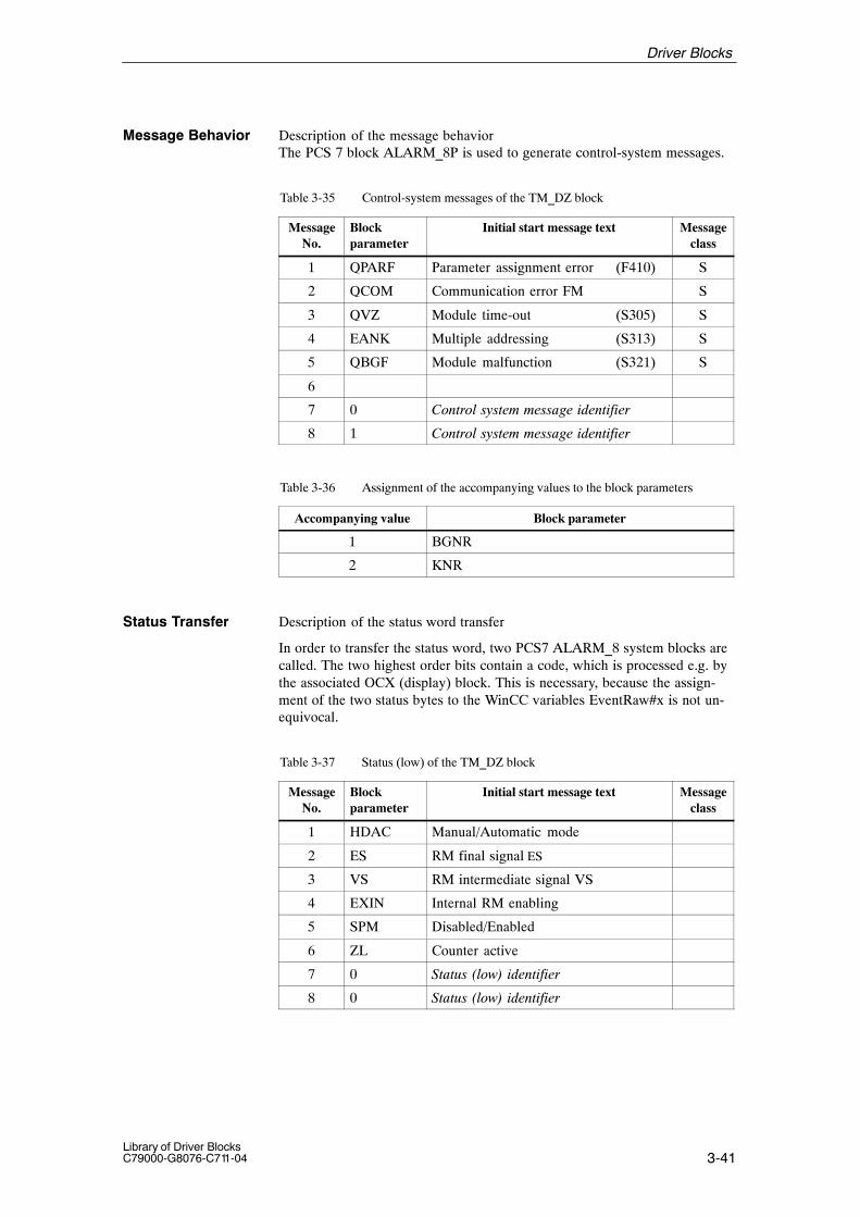
3-41Library of Driver BlocksC79000-G8076-C711-04
Message Behavior Description of the message behaviorThe PCS 7 block ALARM_8P is used to generate control-system messages.
Table 3-35 Control-system messages of the TM_DZ block
MessageNo.
Blockparameter
Initial start message text Messageclass
1 QPARF Parameter assignment error (F410) S
2 QCOM Communication error FM S
3 QVZ Module time-out (S305) S
4 EANK Multiple addressing (S313) S
5 QBGF Module malfunction (S321) S
6
7 0 Control system message identifier
8 1 Control system message identifier
Table 3-36 Assignment of the accompanying values to the block parameters
Accompanying value Block parameter
1 BGNR
2 KNR
Status Transfer Description of the status word transfer
In order to transfer the status word, two PCS7 ALARM_8 system blocks arecalled. The two highest order bits contain a code, which is processed e.g. bythe associated OCX (display) block. This is necessary, because the assign-ment of the two status bytes to the WinCC variables EventRaw#x is not un-equivocal.
Table 3-37 Status (low) of the TM_DZ block
MessageNo.
Blockparameter
Initial start message text Messageclass
1 HDAC Manual/Automatic mode
2 ES RM final signal ES
3 VS RM intermediate signal VS
4 EXIN Internal RM enabling
5 SPM Disabled/Enabled
6 ZL Counter active
7 0 Status (low) identifier
8 0 Status (low) identifier
Driver Blocks

3-42Library of Driver Blocks
C79000-G8076-C711-04
Table 3-38 Status (high) of the TM_DZ block
MessageNo.
Blockparameter
Initial start message text Messageclass
1 UMGF External fault
2 Common alarmUMGF v S80 v S4 v S10 v S16 v S31
ST
3
4
5 I/O faultS80 v S4 v S10 v S16 v S31
6 S80 I/O fault S80
7 1 Status (high) identifier
8 0 Status (high) identifier
For this driver block an allocated display block is realized in the OS.See next section.
Operating andMonitoring via OS
Driver Blocks

3-43Library of Driver BlocksC79000-G8076-C711-04
Operating and monitoring of the TM_DZ block via the corresponding“NORA” requires a corresponding proportioning counter module.The modes “Enable/Disable Counter Output“ (FR,SP) and “Set counter”,“Reset Counter” (ZS, ZR) can only be changed when manual mode is active;else a Windows Message Box will appear.
Changing of parameters is only possible, if the adequate input privilege isactive; else a Windows Message Box will appear.
Input privilege = 0 the privilege is not limited.Input privilege = 1: Changing modesInput privilege = 2: Changing OE/ UE, OV/ UV
The modes of the TM_DZ block (manual / automatic, enable/disable counteroutput, set/reset counter) can be changed by clicking on the highlighted area.A box will then appear, where the actual mode is accentuated. After acknow-ledgement (clicking on the desired mode) and then on the OK-button the boxdisappears and the command is transferred to the AS. After the AS has chan-ged the mode, the new mode is shown. Klicking on the Cancel Button willclose the box.
(name of OCX: S7.G_DZ resp. S7.K_DZ)
Name Source / Input (AS) Operator-Controllable ?
Technolog. name ATN noCurrent count X noFinal value (automatic) EWA noIntermediate value (automatic) VWA noFault alarm S4 S4 noFault alarm S10 S10 noFault alarm S16 S16 noFault alarm S31 S31 noFault alarm S80 S80 noModule fault BGF noUpper range limit XE1 yes, in loop displaySetpoint final value EW yesLower range limit XA1 yes, in loop displayUpper control limit XE2 yes, in loop displaySetpoint intermediate value VW yesLower control limit XA2 yes, in loop displaySet counter ZS / state yes, in manual modeReset counter ZR yes, in manual modeDisable counter output SP / state yes, in manual modeEnable counter output FR / state yes, in manual modeAutomatic mode A / state yesManual mode H / state yesMnemonic name EW TEW noMnemonic name VW TVW noMnemonic name X TX noMnemonic name ZS TZS noMnemonic name ZR TZR noMnemonic name A TA noMnemonic name H TH noMnemonic name SP TSP noMnemonic name FR TFR noQuantity of measurement X EHTX noPCS fault (External fault) state no
Standardized Dis-play for the TM_DZblock
Driver Blocks

3-44Library of Driver Blocks
C79000-G8076-C711-04
Figure 3-3 Display of the DZ block
On the right of the final signal indicator the final value EWA is displayed, onthe right of the intermediate signal indicator the intermediate value VWA isdisplayed. The symbol situated between these is the counter’s state:green / red = counter active/ not active.
The white bar on the left side of the actual value (X) bar represents the inter-mediate value VWA.
The modes Internal/ External are displayed only, but are not operator-control-lable.
Driver Blocks
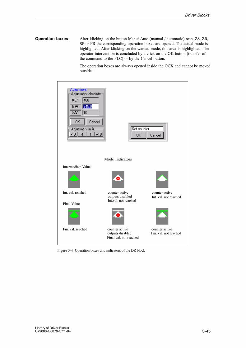
3-45Library of Driver BlocksC79000-G8076-C711-04
After klicking on the button Manu/ Auto (manual / automatic) resp. ZS, ZR,SP or FR the corresponding operation boxes are opened. The actual mode ishighlighted. After klicking on the wanted mode, this area is highlighted. Theoperator intervention is concluded by a click on the OK-button (transfer ofthe command to the PLC) or by the Cancel button.
The operation boxes are always opened inside the OCX and cannot be movedoutside.
Mode Indicators
Intermediate Value
Final Value
Int. val. reached counter activeoutputs disabled
Final val. not reached
counter activeInt. val. not reached
Fin. val. reached counter activeoutputs disabled
Int.val. not reached
counter activeFin. val. not reached
Figure 3-4 Operation boxes and indicators of the DZ block
Operation boxes
Driver Blocks

3-46Library of Driver Blocks
C79000-G8076-C711-04
The following tables present the input and output bars of the block.
Table 3-39 Input bar
Element Meaning Type Initialvalue
Attr. O&M
Permittedvalues
XE1 Upper range limit REAL 100,0 Q B
XA1 Lower range limit REAL 0,0 Q B
XE2 Upper control limit REAL 100,0 Q B
XA2 Lower control limit REAL 0,0 Q B
EWAC Setpoint final value (automatic) REAL 0,0 Q
VWAC Setpoint intermediate value (automatic) REAL 0,0 Q
KF Correcting factor REAL 1,0 Q
TM Measuring time / overshoot time REAL 0,0 Q
ZSAC Set counter (automatic) BOOL 0 Q
ZRAC Reset counter (automatic) BOOL 0 Q
FRSP Enable / Disable BOOL 0 Q
AC Automatic BOOL 0 Q
OGUG Selector UG/OG BOOL 0 Q
VR Setpoint V/R, 0/1 BOOL 0 Q
UMGF External fault BOOL 0 Q
BGNR Module number INT –1 0...60, 100...160
KNR Channel number INT 0 0...63
TEW Text for final value STRING2 ’EW’ U B
TVW Text for intermediate value STRING2 ’VW’ U B
TX Text for current value STRING2 ’X’ U B
TZS Text for set counter STRING2 ’ZS’ U B
TZR Text for reset counter STRING2 ’ZR’ U B
TA Text for automatic mode STRING2 ’A’ U B
TH Text for manual mode STRING2 ’H’ U B
TSP Text for disable STRING2 ’SP’ U B
TFR Text for enable STRING2 ’FR’ U B
EHTX Physical quantity STRING6 ’*EHTX*’ B
ATN Technological name STRING16 ‘*TECHNO-LOG.NAME*
B
EN_MSG Enable control-system messages and status BOOL 0 Q
EV_ID1 Message number (status low) DWORD 0 U
EV_ID2 Message number (status high) DWORD 0 U
EV_ID3 Message number (I&C) DWORD 0 U
I/O Bars
Driver Blocks
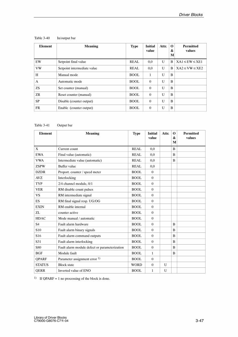
3-47Library of Driver BlocksC79000-G8076-C711-04
Table 3-40 In/output bar
Element Meaning Type Initialvalue
Attr. O&M
Permittedvalues
EW Setpoint final value REAL 0,0 U B XA1�EW�XE1
VW Setpoint intermediate value REAL 0,0 U B XA2�VW�XE2
H Manual mode BOOL 1 U B
A Automatic mode BOOL 0 U B
ZS Set counter (manual) BOOL 0 U B
ZR Reset counter (manual) BOOL 0 U B
SP Disable (counter output) BOOL 0 U B
FR Enable (counter output) BOOL 0 U B
Table 3-41 Output bar
Element Meaning Type Initialvalue
Attr. O&M
Permittedvalues
X Current count REAL 0,0 B
EWA Final value (automatic) REAL 0,0 B
VWA Intermediate value (automatic) REAL 0,0 B
ZSPW Buffer value REAL 0,0
DZDR Proport. counter / speed meter BOOL 0
AVZ Interlocking BOOL 0
TYP 2/4 channel module, 0/1 BOOL 0
VER RM disable count pulses BOOL 0
VS RM intermediate signal BOOL 0
ES RM final signal resp. UG/OG BOOL 0
EXIN RM enable internal BOOL 0
ZL counter active BOOL 0
HDAC Mode manual / automatic BOOL 0
S4 Fault alarm hardware BOOL 0 B
S10 Fault alarm binary signals BOOL 0 B
S16 Fault alarm command outputs BOOL 0 B
S31 Fault alarm interlocking BOOL 0 B
S80 Fault alarm module defect or parameterization BOOL 0 B
BGF Module fault BOOL 1 B
QPARF Parameter assignment error 1) BOOL 0
STATUS Block state WORD 0 U
QERR Inverted value of ENO BOOL 1 U
1) If QPARF = 1 no processing of the block is done.
Driver Blocks

3-48Library of Driver Blocks
C79000-G8076-C711-04
3.12 TM_ZE Metering Pulse Input Block
FB 310
The instance of the driver block must be installed in OB100 (warm restart)and in OB102 (cold restart), in addition to its usual watchdog interrupt OB(for example OB32).
This block is used for acquiring one channel of the TELEPERM M meteringpulse input module 6DS1 607-8AB.
As selected by the scan cycle defined via the CFC, the TM_ZE block pro-cesses one channel (16 bit counter) of the metering pulse input module andpresents the counter value at output ZW. The associated counter is reset whenthe data is read.
Cyclic processing:Output UEBL (overflow) is set to 1 and a system error message is issued ifthe maximum count (= 32.767) is exceeded. ZW is then set = 0.
During processing the driver monitors both the hardware and the value.This results in the following error displays:
� QPARF = 1: Parameter assignment error (see startup characteristics)
� BGF = 1: This output indicates the module or the process valuesare not available. Possible causes:QVZ: Module time-out (incorrect address, incorrect
jumpers or module is defective),EANK:multiple addressing/acknowledge from modules
(incorrect jumper setting)
� ENO = 0: The operating system has recognized a general error byitself (e.g. overflow).
During a startup/initial run or parameter change all parameters are checkedfor permitted values. If the allowed limits are exceeded, the driver sets itsoutput QPARF = 1 and does not carry out any further processing in thesubsequent cycles, e.g. no I/O accesses are done and the outputs retain theirold values.
Time Response Does not exist. If the driver output values are needed from blocks with timeresponse (e.g. closed-loop control block) the driver has to be installed in thesame OB before this block.
Type/Number
Calling OBs
Function
Working Method
Error handling
StartupCharacteristics
Driver Blocks
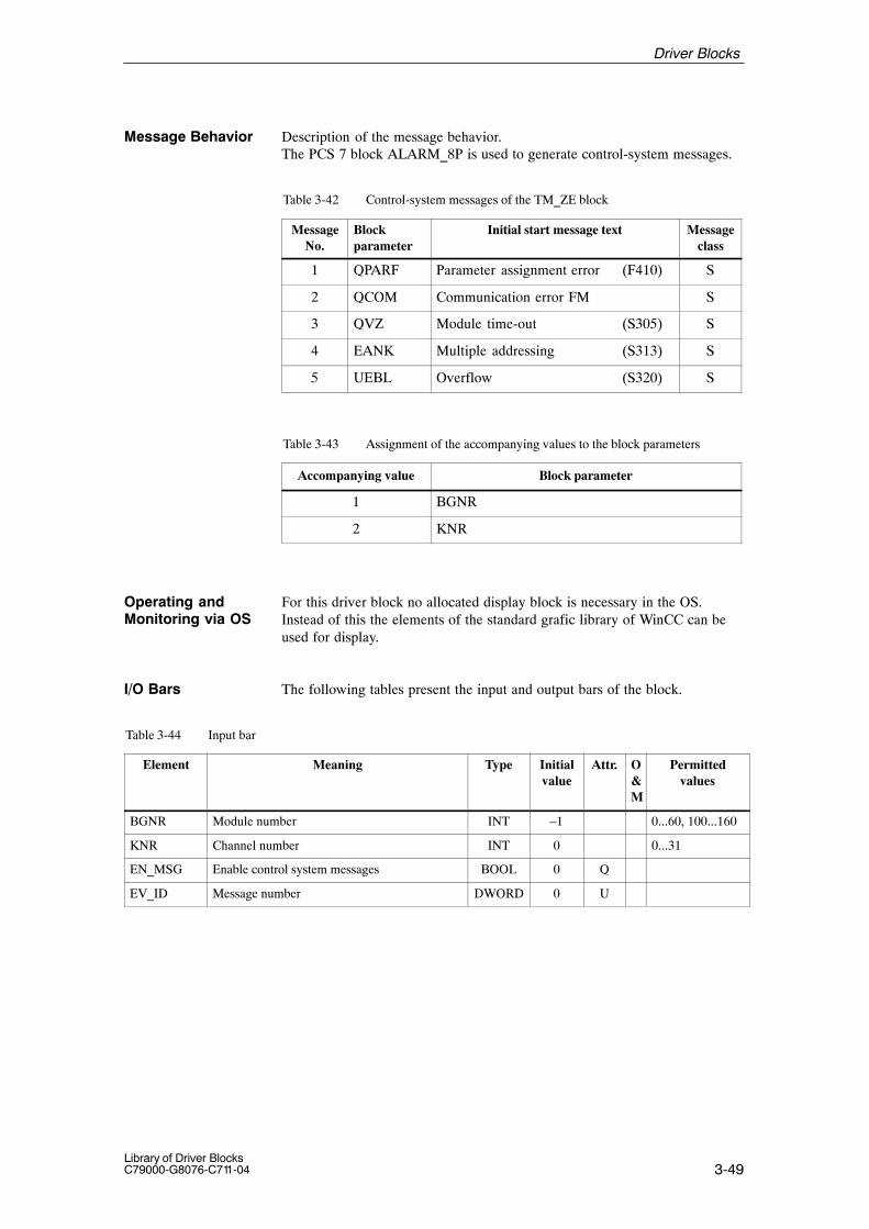
3-49Library of Driver BlocksC79000-G8076-C711-04
Message Behavior Description of the message behavior.The PCS 7 block ALARM_8P is used to generate control-system messages.
Table 3-42 Control-system messages of the TM_ZE block
MessageNo.
Blockparameter
Initial start message text Messageclass
1 QPARF Parameter assignment error (F410) S
2 QCOM Communication error FM S
3 QVZ Module time-out (S305) S
4 EANK Multiple addressing (S313) S
5 UEBL Overflow (S320) S
Table 3-43 Assignment of the accompanying values to the block parameters
Accompanying value Block parameter
1 BGNR
2 KNR
For this driver block no allocated display block is necessary in the OS.Instead of this the elements of the standard grafic library of WinCC can beused for display.
The following tables present the input and output bars of the block.
Table 3-44 Input bar
Element Meaning Type Initialvalue
Attr. O&M
Permittedvalues
BGNR Module number INT –1 0...60, 100...160
KNR Channel number INT 0 0...31
EN_MSG Enable control system messages BOOL 0 Q
EV_ID Message number DWORD 0 U
Operating andMonitoring via OS
I/O Bars
Driver Blocks
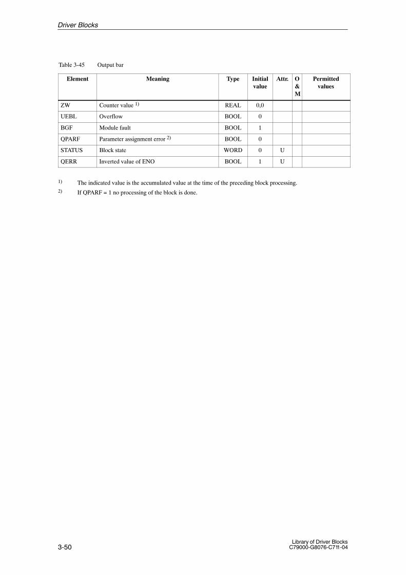
3-50Library of Driver Blocks
C79000-G8076-C711-04
Table 3-45 Output bar
Element Meaning Type Initialvalue
Attr. O&M
Permittedvalues
ZW Counter value 1) REAL 0,0
UEBL Overflow BOOL 0
BGF Module fault BOOL 1
QPARF Parameter assignment error 2) BOOL 0
STATUS Block state WORD 0 U
QERR Inverted value of ENO BOOL 1 U
1) The indicated value is the accumulated value at the time of the preceding block processing.2) If QPARF = 1 no processing of the block is done.
Driver Blocks

3-51Library of Driver BlocksC79000-G8076-C711-04
3.13 TM_EG Driver Block for Open-Loop Control Module
FB 311
The instance of the driver block must be installed in OB100 (warm restart)and in OB102 (cold restart), in addition to its usual watchdog interrupt OB(for example OB32).
The TM_EG block is used for acquiring signals from a TELEPERM M open-loop control module 6DS1 504-8AA or 6DS1 505-8AA and to transfer com-mands to the module.
� Modes
The commands AU, EI and ST entered via the operator-controllable inputsare routed to the open-loop control module if manual mode (H) has been se-lected. The commands AUAC and EIAC or AUBA and EIBA from an auto-matic control are routed to the open-loop control module if automatic mode(A) has been selected.
Manual mode can be selected via the operator controllable input H or theautomatic input HAND. Automatic mode can be selected via the operator-controllable input A, the automatic input AUTO or the input ACBA.
� Configuration instruction
Manual or Automatic modes can only be selected identical for all channels ofone open loop control module 6DS1504 or 6DS1505. Manual or Automaticmode selection must therefore be the same in all driver blocks if several EGdrivers act upon different channels within a module
More information for configuring modules 6DS1 504/505 see chapter 4.7 inthe manual /100/.
� Parameterization
The module number is parameterized via input BGNR, the channel numbervia input KNR. The module type is parameterized via input TYP.
Parameterization of input TYP:
0 : module 6DS15 04-8AA (4 channels)1 : module 6DS15 05-8AA (8 channels)2 : module 6DS15 05-8AA (4 channels)
Parameterization of input KNR following input TYP:
– If input TYP = 0 or 1:KNR = 0..3 or 0...7 corresponds to channels 1...4 or 1...8 respectively
– If input TYP = 2:KNR = 0 : channel 1KNR = 2 : channel 2KNR = 4 : channel 3KNR = 6 : channel 4
Type/Number
Calling OBs
Function
Working Method
Driver Blocks
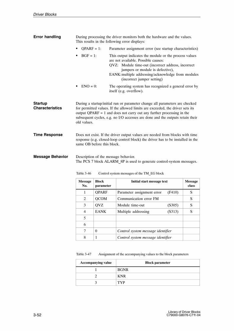
3-52Library of Driver Blocks
C79000-G8076-C711-04
During processing the driver monitors both the hardware and the values.This results in the following error displays:
� QPARF = 1: Parameter assignment error (see startup characteristics)
� BGF = 1: This output indicates the module or the process valuesare not available. Possible causes:QVZ: Module time-out (incorrect address, incorrect
jumpers or module is defective),EANK:multiple addressing/acknowledge from modules
(incorrect jumper setting)
� ENO = 0: The operating system has recognized a general error byitself (e.g. overflow).
During a startup/initial run or parameter change all parameters are checkedfor permitted values. If the allowed limits are exceeded, the driver sets itsoutput QPARF = 1 and does not carry out any further processing in thesubsequent cycles, e.g. no I/O accesses are done and the outputs retain theirold values.
Time Response Does not exist. If the driver output values are needed from blocks with timeresponse (e.g. closed-loop control block) the driver has to be installed in thesame OB before this block.
Message Behavior Description of the message behavior.The PCS 7 block ALARM_8P is used to generate control-system messages.
Table 3-46 Control system messages of the TM_EG block
MessageNo.
Blockparameter
Initial start message text Messageclass
1 QPARF Parameter assignment error (F410) S
2 QCOM Communication error FM S
3 QVZ Module time-out (S305) S
4 EANK Multiple addressing (S313) S
5
6
7 0 Control system message identifier
8 1 Control system message identifier
Table 3-47 Assignment of the accompanying values to the block parameters
Accompanying value Block parameter
1 BGNR
2 KNR
3 TYP
Error handling
StartupCharacteristics
Driver Blocks

3-53Library of Driver BlocksC79000-G8076-C711-04
Status Transfer Description of the status word transfer.In order to transfer the status word, two PCS7 ALARM_8 system blocks arecalled. The two highest order bits contain a code, which is processed e.g. bythe associated OCX (display) block. This is necessary, because the assign-ment of the two status bytes to the WinCC variables EventRaw#x is not un-equivocal.
Table 3-48 Status (low) of the TM_EG block
MessageNo.
Blockparameter
Initial start message text Messageclass
1
2
3 RMEI Open/On
4 RMAU Closed/Off
5 Disable / enable
6 AH Automatic/Manual mode
7 0 Status (low) identifier
8 0 Status (low) identifier
Table 3-49 Status (high) of the TM_EG block
MessageNo.
Blockparameter
Initial start message text Messageclass
1 UMGF External fault
2 Common alarmUMGF S18 v S20
ST
3
4
5 S18 Status discrepancy S18
6 S20 Runtime error S20
7 1 Status (high) identifier
8 0 Status (high) identifier
For this driver block an allocated display block is realized in the OS.See next section.
Operating andMonitoring via OS
Driver Blocks

3-54Library of Driver Blocks
C79000-G8076-C711-04
Representation as a Motor
(name of OCX: S7.G_EG1 resp. S7.K_EG1)
Name Source / Input (AS) Operator- controllable?
Technological name ATN noCommand ON (OPEN) EI / state yes, in manual
ModeCommand OFF (CLOSE) AU / state yes, in manual
Modeautomatic mode A / state yesmanual mode H / state yesPCS fault (external fault) state no
Data for representation as a valve are identical.
(name of OCX: S7.G_EG2, S7.K_EG2)
The next picture shows the EG block in the two representations “switch” and“valve”, as a group and as a loop display each.
Figure 3-5 Bedienboxen des EG-Bausteins
Standardized Dis-play for the TM_EGblock
Driver Blocks

3-55Library of Driver BlocksC79000-G8076-C711-04
After klicking on the area Manu/Auto (manual / automatic resp.), On/Off orClose/Open the corresponding Operation boxes are opened. The actual modeis highlighted. When the desired mode has been klicked that mode becomeshighlighted. The operator intervention is concluded by a click on the OK button (transferof the command to the PLC) or by the Cancel button. In the “valve” representation the texts of the operation box are ”Close” and”Open” instead of ”Off” and ”On”..
Operation box to adjustManual or Automatic: atpresent Manual is active
Operation box to adjustOff or On: at present Offis active
Figure 3-6 Bedienboxen des EG-Bausteins
The following tables present the input and output bars of the block.
Table 3-50 Input bar
Element Meaning Type Initialvalue
Attr. O&M
Permittedvalues
HAND Manual mode BOOL 0 Q
AUTO Automatic mode BOOL 0 Q
AUAC Automatic OFF BOOL 0 Q
EIAC Automatic ON BOOL 0 Q
SAUS Protection OFF BOOL 0 Q
LASP Circuit breaker locked BOOL 0 Q
SPEI Interlocking ON BOOL 0 Q
UMGF External fault BOOL 0 Q
BGNR Module number INT –1 0...60, 100...160
KNR Channel number INT 0 0...7
TYP Configuration definition INT 0 0, 1, 2
AUBA Command OFF (PAA) BOOL 0 Q
EIBA Command ON(PAA) BOOL 0 Q
ACBA Command automatic (PAA) BOOL 0 Q
TEI Text for EI STRING2 ’EI’ U B
TAU Text zu AU STRING2 ’AU’ U B
Operation boxes
I/O Bars
Driver Blocks

3-56Library of Driver Blocks
C79000-G8076-C711-04
Table 3-50 Input bar
Element Permittedvalues
O&M
Attr.Initialvalue
TypeMeaning
TA Text for A STRING2 ’A ’ U B
TH Text for H STRING2 ’H ’ U B
ATN Technological name STRING16 ‘*TECHNO-LOG.NAME*
B
EN_MSG Enable control-system messages and status BOOL 0 Q
EV_ID1 Message number (status low) DWORD 0 U
EV_ID2 Message number (status high) DWORD 0 U
EV_ID3 Message number (I&C) DWORD 0 U
Table 3-51 In/output bar
Element Meaning Type Initialvalue
Attr. O&M
Permittedvalues
H Manual mode BOOL 0 U B
A Automatic mode BOOL 0 U B
AU Command OFF BOOL 0 U B
EI Command ON BOOL 0 U B
ST Command STOP BOOL 0 U B
Table 3-52 Output bar
Element Meaning Type Initialvalue
Attr. O&M
Permittedvalues
RMAU Return data OFF BOOL 0 B
RMEI Return data ON BOOL 0 B
S18 End position error BOOL 0
S20 Time-out BOOL 0
AH Mode 0/1 (automatic/manual) BOOL 0
BGF Module fault BOOL 1 B
QPARF Parameter assignment error 1) BOOL 0
STATUS Block state WORD 0 U
QERR Inverted value of ENO BOOL 1 U
1) If QPARF = 1 no processing of the block is done.
Driver Blocks

3-57Library of Driver BlocksC79000-G8076-C711-04
3.14 TM_EK Driver Block for Open-Loop Control Module – Valve
FB 312
The instance of the driver block must be installed in OB100 (warm restart)and in OB102 (cold restart), in addition to its usual watchdog interrupt OB(for example OB32).
TM_EK is used for acquiring signals from one of the TELEPERM M open-loop control modules 6DS1 501-8AA/-8AB/-8BA/-8BB or of a channel ofone of the TELEPERM M open loop control modules 6DS1 503-8AA/-8BAand to transfer commands to the module. The read signals are presented atthe binary outputs and may be used, for example, by a subgroup controller.
� Modes
In manual mode (Mode H) the commands AU (with OPEN acknowledge-ment), ZU (with CLOSED acknowledgement) and ST entered via the opera-tor-controllable inputs are routed to the open-loop control module.
In automatic mode (Mode A) the commands OPEN (input AUAB), CLOSE(input ZUAB) and STOPP (input STAB) or the commands OPEN/STEP,CLOSE/STEP and STOP/STEP (inputs AUBA, ZUBA, STBA resp.) from anautomatic controller are routed to the module. Priority is not given to auto-matic and automatic/STEP commands.
Simultaneous intervention (protective commands) is possible via the binaryinputs AUSC and ZUSC. These commands have a higher priority; they arerouted to the module as long as they are present. The commands OPEN/CLOSE acknowledgement are also valid during automatic operation.
The modes A/H (automatic/manual mode) can be selected via binary inputAHBA.
� Parameterization
The module number is parameterized via input BGNR and the channel num-ber via input KNR.
channel no. 0: 1-channel open-loop control module6DS1501-8BA/-8BB
channel no.. 1, 2, 3: respective channel of the open-loop control module6DS1503-8BA
� Interlocking monitoring function
The interlocking monitoring function informs the operator of a rejectedOPEN or CLOSE command.
Type/Number
Calling OBs
Function
Working Method
Driver Blocks
3-58Library of Driver Blocks
C79000-G8076-C711-04
Rejection can be caused by– missing process release or– a protective command in the opposite direction
The interlocking monitoring function is shown during the monitoring timespecified via input UZT (default = 10 seconds) in the loop display. After themonitoring time has elapsed, it is deleted from the loop display. A statusmessage is generated if the interlocking monitoring function responds andafter the monitoring time has elapsed.
In the OS subsystems, an operator notice (”B”), which need not be acknow-ledged, is derived at all levels from this function.If the monitoring time hasbeen parameterized = 0, the display is shown for the duration of one cycle.This signal will not be processed in the message processing function MELD.The cabinet or cabinet row lamps are not triggered either when this monito-ring function responds.
� Elektronic position indication
The electronic position indication of the one-channel open-loop control mo-dule 6DS1 501-8BB is issued via analog output 1 within the parameterizedrange limits (Lower range limit/Upper range limit) (input YANZ has beenparameterized = 1). The electronic position indication of the three-channelopen-loop control module can be connected to input YEXT. Input YANZmust then be parameterized = 2.
� Continuous operation / inching operation (set on the module)
Continuous operation is used to drive the actuators from end position to endposition. The return data OPEN and CLOSED on the module is used for di-sconnection.
Inching mode allows an actuator to be adjusted to any intermediate positionbetween the two end positions. An analog position indication must be presentfor inching operation (see picture 2.57). This ESR signal is connected to themodule if the one-channel-open-loop control module 6DS1 501-8BB is used.The ESR signal must be connected to input YEXT of the driver block if themulti-channel open-loop control module 6DS1503-8BA is used.
A comparator is used to determine the difference between position indicationand position setpoint. These values are used by a subsequent increment con-verter to generate OPEN, CLOSE and STOP commands which the EK blockthen transfers to the module. A follow-up circuit ensures that the actuator isheld in its actual position if disturbances are present. In an OS subsystem,operation is performed by entering absolute values or by incremental adjust-ment.
Driver Blocks

3-59Library of Driver BlocksC79000-G8076-C711-04
During processing the driver monitors both the hardware and the values.This results in the following error displays:
� QPARF = 1: Parameter assignment error (see startup characteristics)
� BGF = 1: This output indicates the module or the process valuesare not available. Possible causes:QVZ: Module time-out (incorrect address, incorrect
jumpers or module is defective),EANK:multiple addressing/acknowledge from modules
(incorrect jumper setting)
� ENO = 0: The operating system has recognized a general error byitself (e.g. overflow).
During a startup/initial run or parameter change all parameters are checkedfor permitted values. If the allowed limits are exceeded, the driver sets itsoutput QPARF = 1 and does not carry out any further processing in thesubsequent cycles, e.g. no I/O accesses are done and the outputs retain theirold values.
Time Response Does not exist. If the driver output values are needed from blocks with timeresponse (e.g. closed-loop control block) the driver has to be installed in thesame OB before this block.
Message Behavior Description of the message behavior.The PCS 7 block ALARM_8P is used to generate control-system messages.
Table 3-53 Control-system messages of the TM_EK block
MessageNo.
Blockparameter
Initial start message text Messageclass
1 QPARF Parameter assignment error (F410) S
2 QCOM Communication error FM S
3 QVZ Module time-out (S305) S
4 EANK Multiple addressing (S313) S
5 S4 v S80 Module malfunction (S321) S
6
7 0 Control system message identifier
8 1 Control system message identifier
Table 3-54 Assignment of the accompanying values to the block parameters
Accompanying value Block parameter
1 BGNR
2 KNR
3 YANZ
Error handling
StartupCharacteristics
Driver Blocks
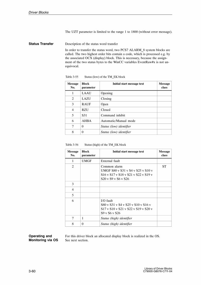
3-60Library of Driver Blocks
C79000-G8076-C711-04
The UZT parameter is limited to the range 1 to 1800 (without error message).
Status Transfer Description of the status word transfer
In order to transfer the status word, two PCS7 ALARM_8 system blocks arecalled. The two highest order bits contain a code, which is processed e.g. bythe associated OCX (display) block. This is necessary, because the assign-ment of the two status bytes to the WinCC variables EventRaw#x is not un-equivocal.
Table 3-55 Status (low) of the TM_EK block
MessageNo.
Blockparameter
Initial start message text Messageclass
1 LAAU Opening
2 LAZU Closing
3 RAUF Open
4 RZU Closed
5 S31 Command inhibit
6 AHBA Automatic/Manual mode
7 0 Status (low) identifier
8 0 Status (low) identifier
Table 3-56 Status (high) of the TM_EK block
MessageNo.
Blockparameter
Initial start message text Messageclass
1 UMGF External fault
2 Common alarmUMGF S80 v S31 v S4 v S25 v S10 vS16 v S17 v S18 v S21 v S22 v S19 vS20 v S9 v S6 v S26
ST
3
4
5
6 I/O faultS80 v S31 v S4 v S25 v S10 v S16 vS17 v S18 v S21 v S22 v S19 v S20 vS9 v S6 v S26
7 1 Status (high) identifier
8 0 Status (high) identifier
For this driver block an allocated display block is realized in the OS.See next section.
Operating andMonitoring via OS
Driver Blocks

3-61Library of Driver BlocksC79000-G8076-C711-04
After the OCX has been placed by the WinCC-Grafics Designer the blockspecific properties box has to be called by a double click on the OCX. Theblock instance and other parameters can then be entered.
Changing of parameters is only possible, if the adequate input privilege isactive; else a Windows Message Box will appear.
Input privilege = 0 the privilege is not limited.Input privilege = 1: Changing modes
The modes of the TM_EK block (Open, Close, Stop) can be changed by clik-king on the highlighted area. A box will then appear, where the actual modeis accentuated. After acknowledgemenet (clicking on the desired mode) andthen on the OK-button the box disappears and the command is transferred tothe AS. After the AS has changed the mode, the new mode is shown. Klik-king on the Cancel Button will close the box.
Configuring the button text:
In continuous operation mode (DLBT = 0) the 2nd character of the TY stringhas to be set to ’*’. The TZU, TST, and TAU strings must not include a ’*’, ifthey should be operated.
In inching operation mode (DLBT = 1) the 2nd character of the TZU, TST,and TAU strings has to be set to ’*’. The TY string must not include a ’*’, ifit should be operated.
A dynamic switchover of the continuous / inching operation mode duringrun–time must not be realized, as no automatic adjustment of the strings willbe possible.
Display 1 (name of OCX: S7.G_EK resp. S7.K_EK)
Name Source / Input (AS) Operator-Controllable ?
Technological name ATN noElectronic position indication YESR noFault alarm S25 S25 noFault alarm S10 S10 noFault alarm S16 S16 noFault alarm S31 S31 noFault alarm S17 S17 noFault alarm S18 S18 noFault alarm S21 S21 noFault alarm S22 S22 noFault alarm S19 S19 noFault alarm S20 S20 noFault alarm S9 S9 noFault alarm S26 S26 noFault alarm S6 S6 noFault alarm S4 S4 noFault alarm S80 S80 noModule fault BGF noUpper range limit Y YME noLower range limit Y YMA no
Standardized Dis-play for the TM_EK block
Driver Blocks

3-62Library of Driver Blocks
C79000-G8076-C711-04
Manipulated value Y Y noOpen AU / state yes, in manual modeClose ZU / state yes, in manual modeStop ST / state yes, in manual modemnemonic name CLOSED TZU nomnemonic name STOP TST nomnemonic name OPEN TAU nomnemonic name Y TY noQuantity Y EHT noPCS fault (External fault) state no
After the OCX has been placed by the WinCC-Grafics Designer the blockspecific properties box has to be called by a double click on the OCX. Theblock instance and other parameters can then be entered.
Changing of parameters is only possible, if the adequate input privilege isactive; else a Windows Message Box will appear.
Input privilege = 0 the privilege is not limited.Input privilege = 1: Changing modes
The modes of the TM_EK block (Open, Close, Stop) can be changed by clik-king on the highlighted area. A box will then appear, where the actual modeis accentuated. After acknowledgemenet (clicking on the desired mode) andthen on the OK-button the box disappears and the command is transferred tothe AS. After the AS has changed the mode, the new mode is shown. Klik-king on the Cancel Button will close the box.
Figure 3-7 Display of the EK block
Standardized Dis-play for the TM_EK block
Driver Blocks
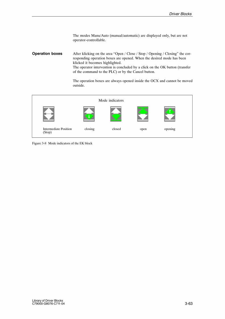
3-63Library of Driver BlocksC79000-G8076-C711-04
The modes Manu/Auto (manual/automatic) are displayed only, but are notoperator-controllable.
After klicking on the area “Open / Close / Stop / Opening / Closing” the cor-responding operation boxes are opened. When the desired mode has beenklicked it becomes highlighted.The operator intervention is concluded by a click on the OK button (transferof the command to the PLC) or by the Cancel button.
The operation boxes are always opened inside the OCX and cannot be movedoutside.
Mode indicators
Intermediate Position(Stop)
closing closed open opening
Figure 3-8 Mode indicators of the EK block
Operation boxes
Driver Blocks

3-64Library of Driver Blocks
C79000-G8076-C711-04
The following tables present the input and output bars of the block.
Table 3-57 Input bar
Element Meaning Type Initialvalue
Attr. O&M
Permittedvalues
YME Upper range limit für Y/YESR REAL 100,0 Q B
YMA Lower range limit für Y/YESR REAL 0,0 Q B
UZT Alarm duration for interlocking monitoring INT 10 Q 1...1800
AUAB Command OPEN – automatic BOOL 0 Q
ZUAB Command CLOSE – automatic BOOL 0 Q
STAB Command STOP – automatic BOOL 0 Q
AHBA Automatic/manual mode BOOL 0 Q
OFFC Protection – OPEN BOOL 0 Q
ZUSC Protection – CLOSE BOOL 0 Q
AUFR Enable – OPEN BOOL 0 Q
ZUFR Enable – CLOSE BOOL 0 Q
DLBT Continuous /inching operation 0/1 BOOL 0 Q
SPEL Disable end position monitoring BOOL 0 Q
USSC Undervoltage protection BOOL 0 Q
ABA1 Binary output 1 BOOL 0 Q
ABA2 Binary output 2 BOOL 0 Q
UMGF External fault BOOL 0 Q
US Suppression STATUS BOOL 0 Q
BGNR Module number INT –1 0...60, 100...160
KNR Channel number INT 0 0...3
AUBA Command OPEN – automatic/STEP BOOL 0 Q
ZUBA Command CLOSE automatic/STEP BOOL 0 Q
STBA Command STOP automatic/STEP BOOL 0 Q
YANZ Y-display 0=OFF/ 1=Yint./ 2= Yext. INT 0 0, 1, 2
TZU Charcter string for CLOSED STRING2 ’ZU’ U B
TST Character string for STOP STRING2 ’ST’ U B
TAU Character string for OPEN STRING2 ’AU’ U B
TY Character string for Y STRING2 ’Y’ U B
EHT Quantity for Y STRING6 ’*EHT*’ B
ATN Technological name STRING16 ‘*TECHNO-LOG.NAME*
B
EN_MSG Enable control-system messages and status BOOL 0 Q
EV_ID1 Message number (status low) DWORD 0 U
EV_ID2 Message number (status high) DWORD 0 U
EV_ID3 Message number (I&C) DWORD 0 U
I/O Bars
Driver Blocks

3-65Library of Driver BlocksC79000-G8076-C711-04
Table 3-58 In/output bar
Element Meaning Type Initialvalue
Attr. O&M
Permittedvalues
YEXT Position indication Y from external device REAL 0,0 Q
Y Manipulated value Y for inching operation REAL 0,0 B
AU Command OPEN BOOL 0 U B
ZU Command CLOSE BOOL 0 U B
ST Command STOP BOOL 0 U B
Table 3-59 Output bar
Element Meaning Type Initialvalue
Attr. O&M
Permittedvalues
YESR Electronic position indication REAL 0,0 B
ZWST Return data intermediate position BOOL 0
LAAU Return data Opening BOOL 0
RAZU Return data Closing BOOL 0
RNAU Return data NOT OPEN BOOL 0
RAUF Return data OPEN BOOL 0 B
RZU Return data CLOSED BOOL 0 B
RNZU Return data NOT CLOSED BOOL 0
TAUF Key OPEN BOOL 0
TAZU Key CLOSED BOOL 0
TSTP Key STOP BOOL 0
ABE1 (Command CLOSE on module) BOOL 0
ABE2 (Command OPEN on module) BOOL 0
S25 Power section failure BOOL 0 B
S10 Binary signal monitoring has responded BOOL 0 B
S16 Command output failure BOOL 0 B
S31 Interlocking monitoring function has responded BOOL 0 B
S17 End position monitoring ‘OPEN’ BOOL 0 B
S18 End position monitoring ‘CLOSED’ BOOL 0 B
S21 Torque monitoring OPEN has responded BOOL 0 B
S22 Torque monitoring CLOSED has responded BOOL 0 B
S19 Run time monitoring OPEN BOOL 0 B
S20 Run time monitoring CLOSED BOOL 0 B
S9 Analog signal monitoring has responded BOOL 0 B
S26 Test position of switching device BOOL 0 B
S6 Control station defective BOOL 0 B
S4 Hardware fault detected on module BOOL 0 B
S80 Module failure detected BOOL 0 B
BGF Module fault BOOL 1 B
QPARF Parameter assignment error 1) BOOL 0
STATUS Block state WORD 0 U
QERR Inverted value of ENO BOOL 1 U1) If QPARF = 1 no processing of the block is done.
Driver Blocks

3-66Library of Driver Blocks
C79000-G8076-C711-04
3.15 TM_EU, Driver Block for Open-Loop Control Module – Motor
FB 313
The instance of the driver block must be installed in OB100 (warm restart)and in OB102 (cold restart), in addition to its usual watchdog interrupt OB(for example OB32).
TM_EU is used for acquiring signals from one of the TELEPERM M open-loop control modules 6DS1 500-8AA/-8BA or of a channel of one of the TE-LEPERM M open loop control modules 6DS1 502-8AA/-8BA and to transfercommands to the module. The read signals are presented at the binary out-puts and may be used, for example, by a subgroup controller.
� Modes
In manual mode (Mode H) the commands ON (EI, with acknowledgement)and OFF (AU, with acknowledgement) entered via the operator-controllableinputs are routed to the open-loop control module.
In automatic mode (Mode A) the commands ON (input EIAB) or OFF (inputAUAB) or the commands ON/OFF-automatic/STEP (inputs BNEA andBNAA) from an automatic controller are routed to the module.
Priority is not given to automatic and automatic/STEP commands. Simulta-neous operator interventions are possible via the binary inputs. These com-mands have a higher priority; they are routed to the module as long as theyare present. The commands acknowledgement ON/OFF (EI,AU) are also va-lid during automatic operation.The modes A/H (automatic/manual mode) canbe selected via binary input AHBA.
� Parameterization
The module number is parameterized via input BGNR and the channel num-ber via input KNR.
channel-Nr. 0: 1-channel open-loop control module 6DS1500-8BAchannel-Nr. 1,2,3: respective channel of the open-loop control module
6DS1 502-8BA.
� Interlocking monitoring function
The interlocking monitoring function informs the operator of a rejected ONor OFF command.
Rejection can be caused by (output S31):– missing process release or– a protective command in the opposite direction
Type/Number
Calling OBs
Function
Working Method
Driver Blocks
3-67Library of Driver BlocksC79000-G8076-C711-04
The interlocking monitoring function is shown during the monitoring timespecified via input UZT (default = 10 seconds) in the loop display. After themonitoring time has elapsed, it is deleted from the loop display. A statusmessage is generated if the interlocking monitoring function responds andafter the monitoring time has elapsed.
In the OS subsystems, an operator notice (”B”), which need not be acknow-ledged, is derived at all levels from this function.If the monitoring time hasbeen parameterized = 0, the display is shown for the duration of one cycle. This signal will not be processed in the message processing function MELD.The cabinet or cabinet row lamps are not triggered either when this monito-ring function responds.
� Motor current display
The motor current is fed as an analog signal to input AW. Normalization pa-rameters are entered via input AWME (Upper range limit) and input AWMA(Lower range limit).
During processing the driver monitors both the hardware and the values.This results in the following error displays:
� QPARF = 1: Parameter assignment error (see startup characteristics)
� BGF = 1: This output indicates the module or the process valuesare not available. Possible causes:QVZ: Module time-out (incorrect address, incorrect
jumpers or module is defective),EANK:multiple addressing/acknowledge from modules
(incorrect jumper setting)
� ENO = 0: The operating system has recognized a general error byitself (e.g. overflow).
During a startup/initial run or parameter change all parameters are checkedfor permitted values. If the allowed limits are exceeded, the driver sets itsoutput QPARF = 1 and does not carry out any further processing in thesubsequent cycles, e.g. no I/O accesses are done and the outputs retain theirold values.
Time Response Does not exist. If the driver output values are needed from blocks with timeresponse (e.g. closed-loop control block) the driver has to be installed in thesame OB before this block.
Message Behavior Description of the message behavior.The PCS 7 block ALARM_8P is used to generate control-system messages.
Error handling
StartupCharacteristics
Driver Blocks
3-68Library of Driver Blocks
C79000-G8076-C711-04
Table 3-60 Control-system messages of the TM_EU block
MessageNo.
Blockparameter
Initial start message text Messageclass
1 QPARF Parameter assignment error (F410) S
2 QCOM Communication error FM S
3 QVZ Module time-out (S305) S
4 EANK Multiple addressing (S313) S
5 QBGF Module malfunction (S321) S
6
7 0 Contro system message identifier
8 1 Control system message identifier
Table 3-61 Assignment of the accompanying values to the block parameters
Accompanying value Block parameter
1 BGNR
2 KNR
The UZT parameter is limited to the range 1 to 1800 (without error message).
Status Transfer Description of the status word transfer.In order to transfer the status word, two PCS7 ALARM_8 system blocks arecalled. The two highest order bits contain a code, which is processed e.g. bythe associated OCX (display) block. This is necessary, because the assign-ment of the two status bytes to the WinCC variables EventRaw#x is not un-equivocal.
Table 3-62 Status (low) of the TM_EU block
MessageNo.
Blockparameter
Initial start message text Messageclass
1 RMEI On
2 RMAU Off
3 S80 I/O fault S80
4 I/O faultS80 v S31 v S4 v S25 v S10 v S16 vS17 v S18 v S19 v S20 v S6 v S26
5 S31 Command inhibit
6 AHBA Automatic/Manual mode
7 0 Status (low) identifier
8 0 Status (low) identifier
Driver Blocks
3-69Library of Driver BlocksC79000-G8076-C711-04
Table 3-63 Status (high) of the TM_EU block
MessageNo.
Blockparameter
Initial start message text Messageclass
1 UMGF External fault
2 Common alarmUMGF v S80 v S31 v S4 v S25 v S10 vS16 v S17 v S18 v S19 v S20 v S6 vS26
ST
3
4
5
6
7 1 Status (high) identifier
8 0 Status (high) identifier
For this driver block an allocated display block is realized in the OS.See next section.
After the OCX has been placed by the WinCC-Grafics Designer the blockspecific properties box has to be called by a double click on the OCX. Theblock instance and other parameters can then be entered.
Changing of parameters is only possible, if the adequate input privilege isactive; else a Windows Message Box will appear.
Input privilege = 0 the privilege is not limited.Input privilege = 1: Changing modes
The modes of the TM_EU block (On/Off) can be changed by clicking on thehighlighted area. A box will then appear, where the actual mode is accentua-ted. After acknowledgement (clicking on the desired mode) and then on theOK-button the box disappears and the command is transferred to the AS.After the AS has changed the mode, the new mode is shown. Klicking on theCancel Button will close the box.
Operating andMonitoring via OS
Standardized Dis-play for the EU block
Driver Blocks

3-70Library of Driver Blocks
C79000-G8076-C711-04
Display 1 (name of OCX: S7.G_EU resp. S7.K_EU)
Name Source / Input (AS) Operator-Controllable?
Technological name ATN noFault alarm S25 S25 noFault alarm S10 S10 noFault alarm S16 S16 noFault alarm S31 S31 noFault alarm S18 S18 noFault alarm S17 S17 noFault alarm S26 S26 noFault alarm S20 S20 noFault alarm S19 S19 noFault alarm S6 S6 noFault alarm S4 S4 noFault alarm S80 S80 noModule fault BGF noUpper range limit (motor current) AWME noMotor current AW noLower range limit (motor current) AWMA noCommand ON EI / state yes, in manual modeCommand OFF AU / state yes, in manual modeMnemonic name OFF TAU noMnemonic name ON TEI noQuantity X EHT noPCS fault (External fault) state no
Figure 3-9 Display of the EU block
The modes Manu/Auto (manual/automatic) are displayed only, but are notoperator-controllable.
Driver Blocks
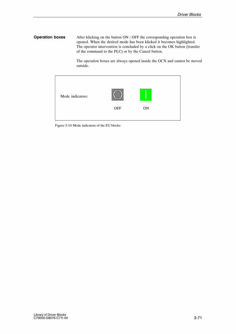
3-71Library of Driver BlocksC79000-G8076-C711-04
After klicking on the button ON / OFF the corresponding operation box isopened. When the desired mode has been klicked it becomes highlighted.The operator intervention is concluded by a click on the OK button (transferof the command to the PLC) or by the Cancel button.
The operation boxes are always opened inside the OCX and cannot be movedoutside.
Mode indicators:
OFF ON
Figure 3-10 Mode indicators of the EU blocks
Operation boxes
Driver Blocks

3-72Library of Driver Blocks
C79000-G8076-C711-04
The following tables present the input and output bars of the block.
Table 3-64 Input bar
Element Meaning Type Initialvalue
Attr. O&M
Permittedvalues
AWME Upper range limit REAL 100,0 Q B
AW Allocated analog value / interconnectable REAL 0,0 Q B
AWMA Lower range limit REAL 0,0 Q B
UZT Alarm duration for interlocking REAL 10 Q 1...1800
EIAB Command ON – automatic BOOL 0 Q
AUAB Command OFF – automatic BOOL 0 Q
AHBA Automatic / manual mode BOOL 0 Q
EISC Protection – ON BOOL 0 Q
OFFC Protection – OFF BOOL 0 Q
EIFR Enable – ON BOOL 0 Q
AUFR Enable – OFF BOOL 0 Q
USSC Undervoltage protection BOOL 0 Q
SPEL Disable end position monitoring for protec-tive command
BOOL 0 Q
DLBT Continuous operation BOOL 0 Q
ABA1 1) Binary output 1 BOOL 0 Q
ABA2 1) Binary output 2 BOOL 0 Q
UMGF External fault BOOL 0 Q
US Suppression STATUS BOOL Q
BGNR Module number INT –1 0...60, 100...160
KNR Channel number INT 0 0...3
BNEA Command ON automatic / STEP BOOL 0 Q
BNAA Command OFF automatic / STEP BOOL 0 Q
TAU Text for OFF STRING2 ’AU’ U B
TEI Text for ON STRING2 ’EI’ U B
EHT Quantity STRING6 ’*EHT*’ B
ATN Technological name STRING16 ‘*TECHNO-LOG.NAME*
B
EN_MSG Enable control-system messages and status BOOL 0 Q
EV_ID1 Message number (status low) DWORD 0 U
EV_ID2 Message number (status high) DWORD 0 U
EV_ID3 Message number (I&C) DWORD 0 U
I/O Bars
Driver Blocks

3-73Library of Driver BlocksC79000-G8076-C711-04
Table 3-65 In/output bar
Element Meaning Type Initialvalue
Attr. O&M
Permittedvalues
EI Command ON BOOL 0 U B
AU Command OFF BOOL 0 U B
Table 3-66 Output bar
Element Meaning Type Initialvalue
Attr. O&M
Permittedvalues
RMAU Return data OFF BOOL 0 B
RMEI Return data ON BOOL 0 B
TAUS Key OFF BOOL 0
TEIN Key ON BOOL 0
ABE1 1) Process Command ON BOOL 0
ABE2 1) Process Command OFF BOOL 0
S25 Power section failure BOOL 0 B
S10 Binary signal monitoring has responded BOOL 0 B
S16 Command outputs have failed BOOL 0 B
S31 Interlocking monitoring function has responded BOOL 0 B
S18 End position monitoring ‘OFF’ BOOL 0 B
S17 End position monitoring ‘ON’ BOOL 0 B
S26 Test position switching device BOOL 0 B
S20 Run time monitoring ‘OFF’ BOOL 0 B
S19 Run time monitoring ‘ON’ BOOL 0 B
S6 Control station defective BOOL 0 B
S4 Hardware fault on module BOOL 0 B
S80 Module failure detected BOOL 0 B
BGF Module fault/ Driver message BOOL 1 B
QPARF Parameter assignment error 1) BOOL 0
STATUS Block state WORD 0 U
QERR Inverted value of ENO BOOL 1 U
1) If QPARF = 1 no processing of the block is done.
Driver Blocks
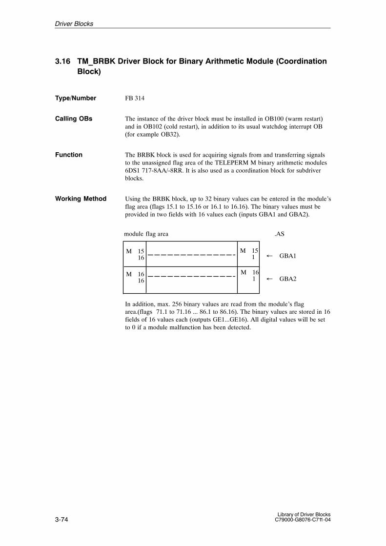
3-74Library of Driver Blocks
C79000-G8076-C711-04
3.16 TM_BRBK Driver Block for Binary Arithmetic Module (CoordinationBlock)
FB 314
The instance of the driver block must be installed in OB100 (warm restart)and in OB102 (cold restart), in addition to its usual watchdog interrupt OB(for example OB32).
The BRBK block is used for acquiring signals from and transferring signalsto the unassigned flag area of the TELEPERM M binary arithmetic modules6DS1 717-8AA/-8RR. It is also used as a coordination block for subdriverblocks.
Using the BRBK block, up to 32 binary values can be entered in the module’sflag area (flags 15.1 to 15.16 or 16.1 to 16.16). The binary values must beprovided in two fields with 16 values each (inputs GBA1 and GBA2).
M 15 1
M 161
M 16 16
M 15 16 � GBA1
� GBA2
module flag area .AS
In addition, max. 256 binary values are read from the module’s flagarea.(flags 71.1 to 71.16 ... 86.1 to 86.16). The binary values are stored in 16fields of 16 values each (outputs GE1...GE16). All digital values will be setto 0 if a module malfunction has been detected.
Type/Number
Calling OBs
Function
Working Method
Driver Blocks

3-75Library of Driver BlocksC79000-G8076-C711-04
M74 . 1
M73 . 1
M71 . 1
M72 . 1
M74 . 16
M73 . 16 � GE3
� GE4
M72 . 16
M71 . 16 � GE1
� GE2
M86 . 1
M86 . 16
� GE16
module flag area AS
The BRBK block coordinates and monitors the data transfer to the module.Subordinate blocks can only exchange data with the module after the BRBKblock has internally enabled data transfer.
� Block sequence
All subdriver blocks (TM_ABR/TM_MSB/TM_TVB) pertaining to aTM_BRBK should be installed in the same processing cycle (before theBRBK) in order to avoid synchronization errors.
� Parameterization / interconnection
The module number is specified via input BGNR.
During processing the driver monitors both the hardware and the values.This results in the following error displays:
� QPARF = 1: Parameter assignment error (see startup characteristics)
� BGF = 1: This output indicates the module or the process valuesare not available. Possible causes:QVZ: Module time-out (incorrect address, incorrect
jumpers or module is defective),EANK:multiple addressing/acknowledge from modules
(incorrect jumper setting)
� ENO = 0: The operating system has recognized a general error byitself (e.g. overflow).
During a startup/initial run or parameter change all parameters are checked for permitted values. If the allowed limits are exceeded, the driver sets its output QPARF = 1 and does not carry out any further processing in the subsequent cycles, e.g. no I/O accesses are done and the outputs retain their old values.
Error handling
StartupCharacteristics
Driver Blocks
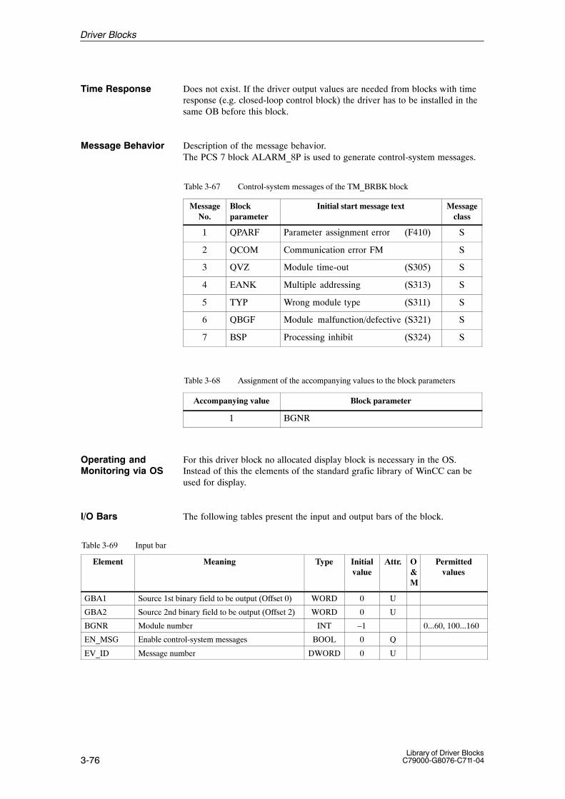
3-76Library of Driver Blocks
C79000-G8076-C711-04
Time Response Does not exist. If the driver output values are needed from blocks with timeresponse (e.g. closed-loop control block) the driver has to be installed in thesame OB before this block.
Message Behavior Description of the message behavior.The PCS 7 block ALARM_8P is used to generate control-system messages.
Table 3-67 Control-system messages of the TM_BRBK block
MessageNo.
Blockparameter
Initial start message text Messageclass
1 QPARF Parameter assignment error (F410) S
2 QCOM Communication error FM S
3 QVZ Module time-out (S305) S
4 EANK Multiple addressing (S313) S
5 TYP Wrong module type (S311) S
6 QBGF Module malfunction/defective (S321) S
7 BSP Processing inhibit (S324) S
Table 3-68 Assignment of the accompanying values to the block parameters
Accompanying value Block parameter
1 BGNR
For this driver block no allocated display block is necessary in the OS.Instead of this the elements of the standard grafic library of WinCC can beused for display.
The following tables present the input and output bars of the block.
Table 3-69 Input bar
Element Meaning Type Initialvalue
Attr. O&M
Permittedvalues
GBA1 Source 1st binary field to be output (Offset 0) WORD 0 U
GBA2 Source 2nd binary field to be output (Offset 2) WORD 0 U
BGNR Module number INT –1 0...60, 100...160
EN_MSG Enable control-system messages BOOL 0 Q
EV_ID Message number DWORD 0 U
Operating andMonitoring via OS
I/O Bars
Driver Blocks

3-77Library of Driver BlocksC79000-G8076-C711-04
Table 3-70 Output bar
Element Meaning Type Initialvalue
Attr. O&M
Permittedvalues
GE1 Target read binary field 1 (Offset 12) WORD 0 U
GE2 Target read binary field 2 (Offset 14) WORD 0 U
GE3 Target read binary field 3 (Offset 16) WORD 0 U
GE4 Target read binary field 4 (Offset 18) WORD 0 U
GE5 Target read binary field 5 (Offset 20) WORD 0 U
GE6 Target read binary field 6 (Offset 22) WORD 0 U
GE7 Target read binary field 7 (Offset 24) WORD 0 U
GE8 Target read binary field 8 (Offset 26) WORD 0 U
GE9 Target read binary field 9 (Offset 28) WORD 0 U
GE10 Target read binary field 10 (Offset 30) WORD 0 U
GE11 Target read binary field 11 (Offset 32) WORD 0 U
GE12 Target read binary field 12 (Offset 34) WORD 0 U
GE13 Target read binary field 13 (Offset 36) WORD 0 U
GE14 Target read binary field 14 (Offset 38) WORD 0 U
GE15 Target read binary field 15 (Offset 40) WORD 0 U
GE16 Target read binary field 16 (Offset 42) WORD 0 U
BGF Module fault BOOL 1
BGNA Module cannot be addressed BOOL 1
BGA Module failure BOOL 1
QPARF Parameter assignment error 1) BOOL 0
KOOR Subdriver coordination BYTE 0
STATUS Block state WORD 0 U
QERR Inverted value of ENO BOOL 1 U
1) If QPARF = 1 no processing of the block is done.
Note
When an instance DB is opened, the parameter names, comments and byteoffsets are visible, so that the user can access the I/O fields GBAx and GExwith his FB.
Driver Blocks

3-78Library of Driver Blocks
C79000-G8076-C711-04
3.17 TM_ABR Analog Input/Output Block for Binary Arithmetic Module
FB 315
The instance of the driver block must be installed in OB100 (warm restart)and in OB102 (cold restart), in addition to its usual watchdog interrupt OB(for example OB32).
The block is used as a driver block to output one and to input up to six analogsignals to the TELEPERM M analog extension module 6DS1 720-8AA viathe binary arithmetic module 6DS1 717-8AA.
Note: The extension module 6DS1 720-8AA cannot be used with a6DS1 717-8RR.
The TM_ABR block cannot be executed without a TM_BRBK block. Thelink to a TM_BRBK block is defined by parameterizing inputs BGNV andKOOR; else an error indication is output.
The number of analog values to be transferred is parameterized via inputANZ. ANZ = 0 means that no execution takes place, ANZ = 1 to 6 specifiesthe number of analog outputs. Input X7 is always transferred to the module ifa value between 1 and 6 has been selected for ANZ. Selectable limits of theanalog inputs are not monitored. Non-availabilty messages and channel rela-ted alarms are provided as output.
ANZ X1 X2 X3 X4 X5 X6 X7
0 – – – – – – –
1 X – – – – – X
2 X X – – – – X
3 X X X – – – X
4 X X X X – – X
5 X X X X X – X
6 X X X X X X X
The channel number is selected at input KNR according to the table:
KNR = 0 = AA,T,1 to AA,T,6 and EA, T,11 = AA,T,7 to AA,T,12 and EA,T,22 = AA,T,13 to AA,T,18 and EA,T,33 = AA,T,19 to AA,T,24 and EA,T,4
Type/Number
Calling OBs
Function
Working Method
Driver Blocks
3-79Library of Driver BlocksC79000-G8076-C711-04
KNR = 0
AA,T,23
AA,T,24
X1
X2
X3
X4
X5
X6
X1
X1
X1
X5
X6
KNR = 1
KNR = 2
KNR = 3
AA,T,1
AA,T,2
AA,T,3
AA,T,4
AA,T,5
AA,T,6
AA,T,7
AA,T,13
AA,T,19
The analog values 1 – 18 (KNR = 0 – 2) are defined as analog values via thehardware inputs or as arithmetic values by user configuration on the module.As the module features a maximum of 18 analog hardware inputs, only arith-metic values should be transferred for the analog values 19 – 24.
Selectable limits of the analog values are not monitored. Non-availabiltymessages and channel related alarms are provided at the outputs X1 to X6.An status signal providing information regarding the fault-free states of theassociated analog signals is issued via the outputs KF1 to KF6.
KFx is present if
– the analog value is not available
– the module cannot be addressed
Driver Blocks

3-80Library of Driver Blocks
C79000-G8076-C711-04
During processing the driver monitors both the hardware and the value.This results in the following error displays:
� QPARF = 1: Parameter assignment error (see startup characteristics)
� BGF = 1: This output indicates the module or the process valuesare not available. Possible causes:QVZ: Module time-out (incorrect address, incorrect
jumpers or module is defective),EANK:multiple addressing/acknowledge from modules
(incorrect jumper setting)
� ENO = 0: The operating system has recognized a general error byitself (e.g. overflow).
During a startup/initial run or parameter change all parameters are checkedfor permitted values. If the allowed limits are exceeded, the driver sets itsoutput QPARF = 1 and does not carry out any further processing in thesubsequent cycles, e.g. no I/O accesses are done and the outputs retain theirold values.
Time Response Does not exist. If the driver output values are needed from blocks with timeresponse (e.g. closed-loop control block) the driver has to be installed in thesame OB before this block.
Message Behavior Description of the message behavior.The PCS 7 block ALARM_8P is used to generate control-system messages.
Table 3-71 Control-system messages of the TM_ABR block
MessageNo.
Blockparameter
Initial start message text Messageclass
1 QPARF Parameter assignment error (F410) S
2 QCOM Communication error FM S
3 QVZ Module time-out (S305) S
4 EANK Multiple addressing (S313) S
5 TYP Wrong module type (S311) S
6 QBGF BGNV / NV / read error (S321) S
7 BRBK_E BRBK block not executed (S324) S
Table 3-72 Assignment of the accompanying values to the block parameters
Accompanying value Block parameter
1 ANZ
2 KNR
For this driver block no allocated display block is necessary in the OS.Instead of this the elements of the standard grafic library of WinCC can beused for display.
Error handling
StartupCharacteristics
Operating andMonitoring via OS
Driver Blocks

3-81Library of Driver BlocksC79000-G8076-C711-04
The following tables present the input and output bars of the block.
Table 3-73 Input bar
Element Meaning Type Initialvalue
Attr. O&M
Permittedvalues
X7 Analog input REAL 0,0 Q
ANZ Number of analog values (0, 1–6) INT 0 0...6
BGNR Module number INT –1 0...60, 100...160
KNR Channel number INT 0 0...3
BGNV Module not available (must be interconnected with the output BGF ofthe BRBK block to which it belongs)
BOOL Q
KOOR Subdriver coordination(This input must be interconnected with theoutput KOOR of the BRBK block to which itbelongs.)
BYTE Q
EN_MSG Enable control-system messages BOOL 0 Q
EV_ID Message number DWORD 0 U
Table 3-74 Output bar
Element Meaning Type Initialvalue
Attr. O&M
Permittedvalues
X1 Analog output 1 REAL 0,0
X2 Analog output 2 REAL 0,0
X3 Analog output 3 REAL 0,0
X4 Analog output 4 REAL 0,0
X5 Analog output 5 REAL 0,0
X6 Analog output 6 REAL 0,0
BGF Module fault BOOL 1
NV1 Non-availability of X1 BOOL 0
NV2 Non-availability of X2 BOOL 0
NV3 Non-availability of X3 BOOL 0
NV4 Non-availability of X4 BOOL 0
NV5 Non-availability of X5 BOOL 0
NV6 Non-availability of X6 BOOL 0
KF1 Channel fault X1 BOOL 0
KF2 Channel fault X2 BOOL 0
KF3 Channel fault X3 BOOL 0
KF4 Channel fault X4 BOOL 0
KF5 Channel fault X5 BOOL 0
KF6 Channel fault X6 BOOL 0
QPARF Parameter assignment error 1) BOOL 0
STATUS Block state WORD 0 U
QERR Inverted value of ENO BOOL 1 U
1) If QPARF = 1 no processing of the block is done.
I/O Bars
Driver Blocks

3-82Library of Driver Blocks
C79000-G8076-C711-04
3.18 TM_TVB Block for Partial Subgroup Control and Preselector Controlof Binary Arithmetic Module
FB 316
The instance of the driver block must be installed in OB100 (warm restart)and in OB102 (cold restart), in addition to its usual watchdog interrupt OB(for example OB32).
This block is used for signal acquisition from and transfer to the TELE-PERM M binary arithmetic module 6DS1 717-8AA/-8RR.
� Common function
The TM_TVB block can only be used together with a TM_BRBK block. Theinterconnections with the TM_BRBK block must be established via inputsBGNV and KOOR, else an error message is output.Input TEVL defines whether a partial subgroup control (TEVL = 1) or a pre-selector control (TEVL = 2) has to be processed.Block processing is inhibited if a control mode has not been selected (TEVL = 0). Block input KNR specifies the channel used for processing ofthe selected control mode.
Notice
The user must ensure that the required function has been implemented on themodule. The system does not perform any check.
Impulse-type module signals (THBA, THBH and TBBL for partial subgroupcontrol and HVW1, HVW2, HVW3 for preselector control) are extended bythe TVB block for the purpose of better representation. The extension time,which is specified in seconds in the UZT element, is startet after each 0/1transition.
� Partial Subgroup Control Mode (element TEVL = 1)
Signals from the TVB block to the module
The TVB block transfers the following input signals to the module:
A : Manual command “automatic” (only effective if FHD=1)H : Manual command “manual” (only effective if FHD=1)QB : AcknowledgementFHD : Enable manual modeBAA : Automatic command “automatic”BAH : Automatic command “manual”BABT : Automatic command “operation”BAST : Automatic command “shutdown”ZWH : Forced manual
Type/Number
Calling OBs
Function
Working Method
Driver Blocks

3-83Library of Driver BlocksC79000-G8076-C711-04
The inputs A, H and QB are reset subsequently. The input QB is transferredto the module like as an A or H manual command without enabling signal(FHD = 0).
Signals from the module to the TVB block
Some of the signals coming from the module are stored in outputs, some ininternal elements.
FUFE : MalfunctionTH : Status “manual”TA : Status “automatic”THBH : Feedback manual command “manual” (1)
THBA : Feedback manual command “automatic” (1)
TST : Status “shutdown”TBT : Status “operation”TBAB : Feedback automatic command “operation”TBAS : Feedback automatic command “shutdown”TZWH : Feedback forced manualTBBL : Command blockedTBAA : Feedback automatic command “automatic mode”TBAH : Feedback automatic command “manual mode”TLAR : Lamp automatic steady lightTLAB : Lamp automatic blinkingTLHR : Lamp manual steady lightTLHB : Lamp manual blinkingTLSR : Lamp fault steady lightTLSB : Lamp fault blinking
(1) Signal is extended
� Preselector control mode (element TEVL=2)
Input BART defines the preselector control mode. Three modes are possible:
1 = Preselection 1-out-of-2 using 1 key2 = Preselection 1-out-of-2 using 2 keys3 = Preselection 1-out-of-3 using 3 keys
Notice
The user must ensure that the mode selected matches the mode configuredon the module. A check is not performed.
Signals from the TVB block to the module
The TVB block transfers the following input signals to the module:
V1 : Preselection 1V2 : Preselection 2 ( mode 2 or 3 only)V3 : Preselection 3 ( mode 3 only)
Driver Blocks

3-84Library of Driver Blocks
C79000-G8076-C711-04
Signals from the module to the TVB block
Some of the signals from the module are stored in outputs, some in internalelements.
VW1 : Feedback output command generating set 1VW2 : Feedback output command generating set 2VW3 : Feedback output command generating set 3HVW1 : Manual operator input preselection 1 (1)
HVW2 : Manual operator input preselection 2 (1)
HVW3 : Manual operator input preselection 3 (1)
LVW1 : Lamp steady light Preselection 1LVW2 : Lamp steady light Preselection 2LVW3 : Lamp steady light Preselection 3(1) signal is extended.
� Parameterization
At input TEVL, the user defines whether a partial subgroup control (TEVL =1) or a preselector control (TEVL = 2) has to be processed. Block processingis disabled if a control mode has not been selected (TEVL = 0).
Input KNR is used for specifying the channel for the control mode selected.
Notice
The user must ensure that the required function has been implemented on themodule. The system does not perform any check.
Status transfer via the bus is suppressed if input US has been set to 1. Statusmessage frame will then no longer be transferred to the OS.Input FHD is used for enabling (FHD = 1) or disabling (FHD = 0) the opera-tor input function (A/H resp. V1/V2/V3).
Impulse-type module signals (THBA, THBH and TBBL for partial subgroupcontrol and HVW1, HVW2, HVW3 for preselector control) are extended bythe TVB block for the purpose of better representation. The extension time,which is specified in seconds in the UZT element, is startet after each 0/1transition.
� Block sequence
In order to avoid synchronization errors, the TVB block should be installedbefore the BRBK block in the same processing cycle. Assignment must beperformed in the BRBK block.
During processing the driver monitors both the hardware and the values.This results in the following error displays:
� QPARF = 1: Parameter assignment error (see startup characteristics)
� BGF = 1: This output indicates the module or the process valuesare not available. Possible causes:QVZ: Module time-out (incorrect address, incorrect
jumpers or module is defective),EANK: multiple addressing/acknowledge from modules
(incorrect jumper setting)
Error handling
Driver Blocks

3-85Library of Driver BlocksC79000-G8076-C711-04
� ENO = 0: The operating system has recognized a general error byitself (e.g. overflow).
During a startup/initial run or parameter change all parameters are checkedfor permitted values. If the allowed limits are exceeded, the driver sets itsoutput QPARF = 1 and does not carry out any further processing in thesubsequent cycles, e.g. no I/O accesses are done and the outputs retain theirold values.
Time Response Does not exist. If the driver output values are needed from blocks with timeresponse (e.g. closed-loop control block) the driver has to be installed in thesame OB before this block.
Message Behavior Description of the message behavior.The PCS 7 block ALARM_8P is used to generate control-system messages.
Table 3-75 Control-system messages of the TM_TVB block
MessageNo.
Blockparameter
Initial start message text Messageclass
1 QPARF / TEVL = 0
Parameter assignment error / Control type missing (F410/S325)
S
2 QCOM Communication error FM S
3 QVZ Module time-out (S305) S
4 EANK Multiple addressing (S313) S
5 TYP Wrong module type (S311) S
6 QBGF /BRBK_E
Module malfunction / BRBK block has failed (S321/S324)
S
7 0 Control system message identifier
8 1 Control system message identifier
Table 3-76 Assignment of the accompanying values to the block parameters
Accompanying value Block parameter
1 TEVL
2 KNR
StartupCharacteristics
Driver Blocks

3-86Library of Driver Blocks
C79000-G8076-C711-04
Status Transfer Description of the status word transfer.
In order to transfer the status word, two PCS7 ALARM_8 system blocks arecalled. The two highest order bits contain a code, which is processed e.g. bythe associated OCX (display) block. This is necessary, because the assign-ment of the two status bytes to the WinCC variables EventRaw#x is not un-equivocal.
Table 3-77 Status (low) of the TM_TVB block
MessageNo.
Blockparameter
Initial start message text Messageclass
1 TA Manual/Automatic mode
2 ST_BT Shutdown/Operation
3 LVW1 Steady light V1
4 LVW2 Steady light V2
5 LVW3 Steady light V3
6 FUFE Malfunction
7 0 Status (low) identifier
8 0 Status (low) identifier
Table 3-78 Status (high) of the TM_TVB block
MessageNo.
Blockparameter
Initial start message text Messageclass
1 BGF Module fault
2 Common alarmFUFE v TZWH v BGF
ST
3
4
5 TZWH Forced manual
6 TBBL Command inhibit
7 1 Status (high) identifier
8 0 Status (high) identifier
For this driver block an allocated display block is realized in the OS.See next section.
Operating andMonitoring via OS
Driver Blocks
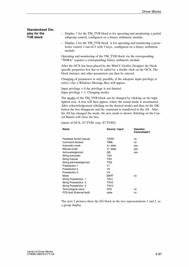
3-87Library of Driver BlocksC79000-G8076-C711-04
– Display 1 for the TM_TVB block is for operating and monitoring a partial subgroup control, configured on a binary arithmetic module.
– Display 2 for the TM_TVB block is for operating and monitoring a prese-lector control 1-out-of-3 with 3 keys., configured on a binary arithmetic module.
Operating and monitoring of the TM_TVB block via the corresponding“NORA” requires a corresponding binary arithmetic module.
After the OCX has been placed by the WinCC-Grafics Designer the blockspecific properties box has to be called by a double click on the OCX. Theblock instance and other parameters can then be entered.
Changing of parameters is only possible, if the adequate input privilege isactive; else a Windows Message Box will appear.
Input privilege = 0 the privilege is not limited.Input privilege = 1: Changing modes
The modes of the TM_TVB block can be changed by clicking on the high-lighted area. A box will then appear, where the actual mode is accentuated.After acknowledgement (clicking on the desired mode) and then on the OK-button the box disappears and the command is transferred to the AS. Afterthe AS has changed the mode, the new mode is shown. Klicking on the Can-cel Button will close the box.
(name of OCX: S7.TVB1 resp. S7.TVB2)
Name Source / input Operator-Controllable?
Feedback forced manual TZWH noCommand blocked TBBL noAutomatic mode A / state yesManual mode H / state yesAcknowledgement QB yesString automatic TXAString manual TXHString acknowledgement TXQPreselection 1 V1Preselection 2 V2Preselection 3 V3Mode BART noString Preselection 1 TXV1String Preselection 2 TXV2String Preselection 3 TXV3Technological name ATN noPCS fault (External fault) state no
The next 2 pictures show the EG block in the two representations 1 and 2, asa group display.
Standardized Dis-play for the TVB block
Driver Blocks

3-88Library of Driver Blocks
C79000-G8076-C711-04
Figure 3-11 Display of the TVB block
After klicking on the highlighted area manual/ automatic resp. operate thecorresponding operation box is opened. The actual mode is highlighted.When the desired mode has been klicked, that mode becomes highlighted.The operator intervention is concluded by a click on the OK button (transferof the command to the PLC) or by the Cancel button.
The operation boxes are always opened inside the OCX and cannot be movedoutside.
Operation boxes
Driver Blocks

3-89Library of Driver BlocksC79000-G8076-C711-04
The following tables present the input and output bars of the block.
Table 3-79 Input bar
Element Meaning Type Initialvalue
Attr. O&M
Permittedvalues
TEVL Control type INT 0 0, 1, 2
BGNR Module number INT –1 0...60, 100...160
KNR Channel number INT 0 1, 2
US Status suppression BOOL 0 Q
FHD Enable manual control BOOL 1 Q B
UZT Delay time for impulse-type module signals/message duration interlocking monitoring
INT 10 Q 1...255
BAA Automatic command “automatic” BOOL 0 Q
BAH Automatic command “manual” BOOL 0 Q
BABT Automatic command “operation” BOOL 0 Q
BAST Automatic command “shutdown” BOOL 0 Q
ZWH Forced manual BOOL 0 Q
BART Mode INT 3 B 1, 2, 3
BAV1 Automatic command Preselection 1 BOOL 0 Q
BAV2 Automatic command Preselection 2 BOOL 0 Q
BAV3 Automatic command Preselection 3 BOOL 0 Q
BGNV Module not available (must be interconnected with the output BGFof the BRBK block to which it belongs)
BOOL 1 Q
KOOR Subdriver coordination(This input must be interconnected with theoutput KOOR of the BRBK block to which itbelongs.)
BYTE 0 Q
TXA Text for automatic STRING2 ’A’ U B
TXH Text for manual STRING2 ’H’ U B
TXQ Text for acknowledgement STRING2 ’QB’ U B
TVW1 Text for Preselection 1 STRING2 ’V1’ U B
TVW2 Text for Preselection 2 STRING2 ’V2’ U B
TVW3 Text for Preselection 3 STRING2 ’V3’ U B
ATN Technological name STRING16 ‘*TECHNO-LOG.NAME*
B
EN_MSG Enable control-system messages and status BOOL 0 Q
EV_ID1 Message number (status low) DWORD 0 U
EV_ID2 Message number (status high) DWORD 0 U
EV_ID3 Message number (I&C) DWORD 0 U
I/O Bars
Driver Blocks

3-90Library of Driver Blocks
C79000-G8076-C711-04
Table 3-80 In/output bar
Element Meaning Type Initialvalue
Attr. O&M
Permittedvalues
A Manual command “automatic” BOOL 0 U B
H Manual command “manual” BOOL 0 U B
QB Acknowledgement BOOL 0 U B
V1 Manual command Preselection 1 BOOL 0 U B
V2 Manual command Preselection 2 BOOL 0 U B
V3 Manual command Preselection 3 BOOL 0 U B
Table 3-81 Output bar
Element Meaning Type Initialvalue
Attr. O&M
Permittedvalues
TA Status automatic BOOL 0
TH Status manual BOOL 0
TBT Status operation BOOL 0
TST Status shutdown BOOL 0
TZWH Feedbach forced manual BOOL 0 B
FUFE Malfunction BOOL 0
TBBL Command blocked BOOL 0 B
VW1 Output command Preselection generating set 1 BOOL 0 B
VW2 Output command Preselection generating set 1 BOOL 0 B
VW3 Output command Preselection generating set 1 BOOL 0 B
THBH Feedback manual command “manual” BOOL 0 U
THBA Feedback manual command “automatic” BOOL 0 U
TBAH Feedback automatic command “manual” BOOL 0 U
TBAA Feedback automatic command “automatic” BOOL 0 U
TBAS Feedback automatic command “shutdown” BOOL 0 U
TBAB Feedback automatic command “operation” BOOL 0 U
TLHB Lamp manual blinking BOOL 0 U
TLHR Lamp manual steady light BOOL 0 U
TLAR Lamp automatic steady light BOOL 0 U
TLAB Lamp automatic blinking BOOL 0 U
TLSR Lamp fault steady light BOOL 0 U
TLSB Lamp fault blinking BOOL 0 U
HVW1 Manual operator input Preselection 1 BOOL 0 U
LVW1 Lamp steady light Preselection 1 BOOL 0 U
HVW2 Manual operator input Preselection 2 BOOL 0 U
LVW2 Lamp steady light Preselection 2 BOOL 0 U
HVW3 Manual operator input Preselection 3 BOOL 0 U
LVW3 Lamp steady light Preselection 3 BOOL 0 U
QPARF Parameter assignment error 1) BOOL 0
STATUS Block state WORD 0 U
QERR Inverted value of ENO BOOL 1 U
1) If QPARF = 1 no processing of the block is done.
Driver Blocks

3-91Library of Driver BlocksC79000-G8076-C711-04
3.19 TM_MSB Block for the ESG Functions “Motor, Valve and ActuatorControl” on the Binary Arithmetic Module
FB 317
The instance of the driver block must be installed in OB100 (warm restart)and in OB102 (cold restart), in addition to its usual watchdog interrupt OB(for example OB32).
This driver block is used for monitoring and controlling the ESG functions“motor, valve and actuator control” of a TELEPERM M binary arithmeticmodule 6DS1 717-8AA/-8RR.
The TM_MSB block can only be used together with a TM_BRBK block. Theinterconnections with the TM_BRBK block must be established via inputsBGNV, BGAE and KOOR.Input BART defines whether the block is to be executed as a motor/valvecontrol (BART = 1) or as an actuator control (BART = 2).Block processing is inhibited if a control mode has not been selected (BART = 0).The ESG block input defines which ESG channel of the block is to be used.
Notice
The user must ensure that the required function has been implemented on themodule. The system does not perform any check.
Impulse-type module signal BBL is extended by the MSB block for the pur-pose of better representation. The extension time, which is specified in se-conds in the UZT element, is startet after each 0/1 transition.
� Signals from the MSB block to the module
The MSB block transfers the following input signals to the module:
AU : Manual command ’OPEN’ (only effective if FHD = 1)ZU : Manual command ’CLOSE’ (only effective if FHD = 1)ST : Manual command ’STOP’ (only effective if FHD = 1 and
BART = 2)QB : AcknowledgementFHD : Manual enablingBAOE: Automatic command ’OPEN’BAS : Automatic command ’CLOSE’FPOE : Process release ’OPEN’FPS : Process release ’CLOSE’SS1 : Aggregate protection ’CLOSE’SS2 : Plant protection ’CLOSE’SOE : Protection ’OPEN’
The inputs AU, ZU, ST and QB are reset subsequently.Input QB is transferred to the module without enabling signal (FHD = 0) inthe same manner as an AU or ZU manual command.
Type/Number
Calling OBs
Function
Working Method
Driver Blocks
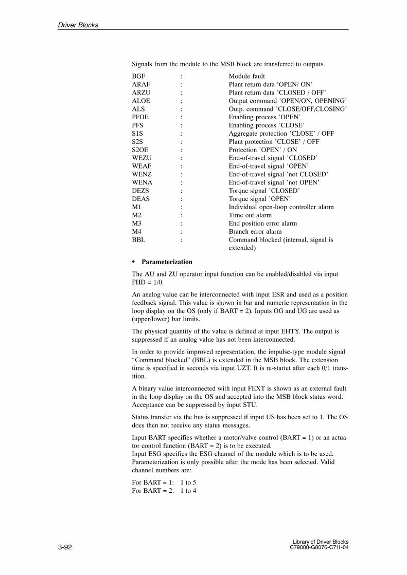
3-92Library of Driver Blocks
C79000-G8076-C711-04
Signals from the module to the MSB block are transferred to outputs.
BGF : Module faultARAF : Plant return data ’OPEN/ ON’ARZU : Plant return data ’CLOSED / OFF’ALOE : Output command ’OPEN/ON, OPENING’ALS : Outp. command ’CLOSE/OFF,CLOSING’PFOE : Enabling process ’OPEN’PFS : Enabling process ’CLOSE’S1S : Aggregate protection ’CLOSE’ / OFFS2S : Plant protection ’CLOSE’ / OFFS2OE : Protection ’OPEN’ / ONWEZU : End-of-travel signal ’CLOSED’WEAF : End-of-travel signal ’OPEN’WENZ : End-of-travel signal ’not CLOSED’WENA : End-of-travel signal ’not OPEN’DEZS : Torque signal ’CLOSED’DEAS : Torque signal ’OPEN’M1 : Individual open-loop controller alarmM2 : Time out alarmM3 : End position error alarmM4 : Branch error alarmBBL : Command blocked (internal, signal is
extended)
� Parameterization
The AU and ZU operator input function can be enabled/disabled via inputFHD = 1/0.
An analog value can be interconnected with input ESR and used as a positionfeedback signal. This value is shown in bar and numeric representation in theloop display on the OS (only if BART = 2). Inputs OG and UG are used as(upper/lower) bar limits.
The physical quantity of the value is defined at input EHTY. The output issuppressed if an analog value has not been interconnected.
In order to provide improved representation, the impulse-type module signal“Command blocked” (BBL) is extended in the MSB block. The extensiontime is specified in seconds via input UZT. It is re-startet after each 0/1 trans-ition.
A binary value interconnected with input FEXT is shown as an external faultin the loop display on the OS and accepted into the MSB block status word.Acceptance can be suppressed by input STU.
Status transfer via the bus is suppressed if input US has been set to 1. The OSdoes then not receive any status messages.
Input BART specifies whether a motor/valve control (BART = 1) or an actua-tor control function (BART = 2) is to be executed.Input ESG specifies the ESG channel of the module which is to be used.Parameterization is only possible after the mode has been selected. Validchannel numbers are:
For BART = 1: 1 to 5For BART = 2: 1 to 4
Driver Blocks

3-93Library of Driver BlocksC79000-G8076-C711-04
The modes “local operation” and “test position” are not actual I/O faults andtherefore need not appear in the status word as I/O faults. To suppress themodes in the status word, the BART parameter is supplemented by the modes11 and 12.
BART functions with:
= 1 “local” and “test” appear in the status word= 2 “local” and “test” appear in the status word= 11 “local” and “test” do not appear in the status word= 12 “local” and “test” do not appear in the status word
Block execution remains disabled if mode (BART=0) and/or channel number(ESG = 0) have not been selected (� S 325).
The user must ensure that the required function has been implemented on themodule. The system does not perform any check.
Block output
BGF 1
S 305
I/O bus
interface module
EANK
Monitoring of BRBK block
System alarm
module
Arithmetic module 6DS1717-8..
S 311T1 ... T8
��������� ������ �����������
��� �����
���� ��� ��� ��������
!" ������ ����
Monitoringof type identifier
> 1
S 321
S 324
S 325
BRBK block: BGF
Channel No./ modeincorrect
QVZ
S 313
Figure 3-12 MSB block, alarm logic
Driver Blocks
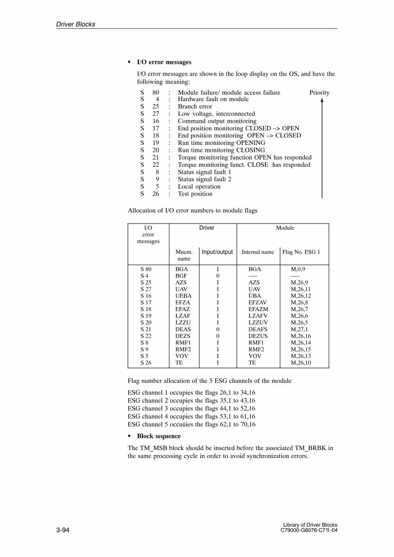
3-94Library of Driver Blocks
C79000-G8076-C711-04
� I/O error messages
I/O error messages are shown in the loop display on the OS, and have thefollowing meaning:
S 80 : Module failure/ module access failure PriorityS 4 : Hardware fault on moduleS 25 : Branch errorS 27 : Low voltage, interconnectedS 16 : Command output monitoringS 17 : End position monitoring CLOSED –> OPENS 18 : End position monitoring OPEN –> CLOSEDS 19 : Run time monitoring OPENINGS 20 : Run time monitoring CLOSINGS 21 : Torque monitoring function OPEN has respondedS 22 : Torque monitoring funct. CLOSE has respondedS 8 : Status signal fault 1S 9 : Status signal fault 2S 5 : Local operationS 26 : Test position
Allocation of I/O error numbers to module flags
I/Oerror
messages
�����#�$� Module
Mnem.name
%��� &�� �� Internal name Flag No. ESG 1
S 80S 4S 25S 27S 16S 17S 18S 19S 20S 21S 22S 8S 9S 5S 26
BGABGFAZSUAVUEBAEFZAEFAZLZAFLZZUDEASDEZSRMF1RMF2VOVTE
I0IIIIIII00IIII
BGA–––AZSUAVÜBAEFZAVEFAZMLZAFVLZZUVDEAFSDEZUSRMF1RMF2VOVTE
M,0,9–––M,26,9M,26,11M,26,12M,26,8M,26,7M,26,6M,26,5M,27,1M,26,16M,26,14M,26,15M,26,13M,26,10
Flag number allocation of the 5 ESG channels of the module
ESG channel 1 occupies the flags 26,1 to 34,16 ESG channel 2 occupies the flags 35,1 to 43,16 ESG channel 3 occupies the flags 44,1 to 52,16 ESG channel 4 occupies the flags 53,1 to 61,16 ESG channel 5 occuüies the flags 62,1 to 70,16
� Block sequence
The TM_MSB block should be inserted before the associated TM_BRBK inthe same processing cycle in order to avoid synchronization errors.
Driver Blocks

3-95Library of Driver BlocksC79000-G8076-C711-04
During processing the driver monitors both the hardware and the values.This results in the following error displays:
� QPARF = 1: Parameter assignment error (see startup characteristics)
� BGF = 1: This output indicates the module or the process valuesare not available. Possible causes:QVZ: Module time-out (incorrect address, incorrect
jumpers or module is defective),EANK: multiple addressing/acknowledge from modules
(incorrect jumper setting)
� ENO = 0: The operating system has recognized a general error byitself (e.g. overflow).
During a startup/initial run or parameter change all parameters are checkedfor permitted values. If the allowed limits are exceeded, the driver sets itsoutput QPARF = 1 and does not carry out any further processing in thesubsequent cycles, e.g. no I/O accesses are done and the outputs retain theirold values.
Time Response Does not exist. If the driver output values are needed from blocks with timeresponse (e.g. closed-loop control block) the driver has to be installed in thesame OB before this block. The PCS 7 block ALARM_8P is used to generatecontrol-system messages.
Message Behavior Description of the message behavior.The PCS 7 block ALARM_8P is used to generate control-system messages.
Table 3-82 Control-system messages of the TM_MSB block
MessageNo.
Blockparameter
Initial start message text Messageclass
1 QPARF /BRBK_F
Parameter assignment error / Mode orchannel no. missing (F410/S325)
S
2 QCOM Communication error FM S
3 QVZ Module time-out (S305) S
4 EANK Multiple addressing (S313) S
5 TYP Wrong module type (S311) S
6 QBGF /BRBK_E
Module malfunction / BRBK block has failed (S321/S324)
S
7 0 Control system message identifier
8 1 Control system message identifier
Table 3-83 Assignment of the accompanying values to the block parameters
Accompanying value Block parameter
1 BART
2 KNR
The UZT parameter is limited to the range 0 to 255 (without error message).
Error handling
StartupCharacteristics
Driver Blocks

3-96Library of Driver Blocks
C79000-G8076-C711-04
Status Transfer Description of the status word transfer
In order to transfer the status word, two PCS7 ALARM_8 system blocks arecalled. The two highest order bits contain a code, which is processed e.g. bythe associated OCX (display) block. This is necessary, because the assign-ment of the two status bytes to the WinCC variables EventRaw#x is not un-equivocal.
Table 3-84 Status (low) of the TM_MSB block
MessageNo.
Blockparameter
Initial start message text Messageclass
1 ALOE Opening
2 ALS Closing
3 ARAF Open / On
4 ARZU Closed / Off
5 LZUB Lamp Closed / Off
6 LAFB Lamp Open / On
7 0 Status (low) identifier
8 0 Status (low) identifier
Table 3-85 Status (high) of the TM_MSB block
MessageNo.
Blockparameter
Initial start message text Messageclass
1 FEXT External fault
2 Common alarmLZUB v LAFB v FEXT v BGF vDEZS v DEAS v LZZU v LZAF vEFAZ v EFZA v AZS v UAV v UEBAv RMF1 v RMF2 (v TE v VOV)
ST
3
4
5 BBL Command inhibit
6 I/O faultBGF v DEZS v DEAS v LZZU vLZAF v EFAZ v EFZA v AZS v UAVv UEBA v RMF1 v RMF2 (v TE vVOV)
7 1 Status (high) identifier
8 0 Status (high) identifier
For this driver block an allocated display block is realized in the OS.See next section.
Operating andMonitoring via OS
Driver Blocks

3-97Library of Driver BlocksC79000-G8076-C711-04
Operating and monitoring of the TM_MSB block via the corresponding“NORA” requires a corresponding binary arithmetic module. After the OCXhas been placed by the WinCC-Grafics Designer the block specific propertiesbox has to be called by a double click on the OCX. The block instance andother parameters can then be entered.
(name of OCX: S7.G_MSB resp. S7.K_MSB)
Name Source / Input (AS) Operator-Controllable?
Module fault BGF noEnable ”process OPEN” PFOE noEnable ”process CLOSE” PFS noAggregate protection “CLOSE” S1S noPlant protection ”CLOSE/OFF” S2S noPlant protection ”OPEN/ON” S2OE noManual command OPEN AU yesManual command CLOSE ZU yesManual command STOP ST yesAcknowledgement QB yesManual enabling FHDMode BART noString OPEN TAU noString CLOSE TZU noString STOP TST noString acknowledgement TQB noTechnological name ATN noPCS fault (External fault) state no
Figure 3-13 Display of the MSB block
Standardized Dis-play for the MSB block
Driver Blocks
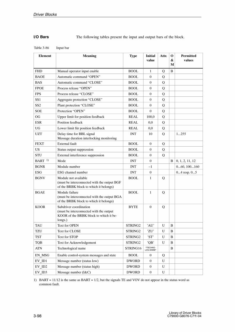
3-98Library of Driver Blocks
C79000-G8076-C711-04
The following tables present the input and output bars of the block.
Table 3-86 Input bar
Element Meaning Type Initialvalue
Attr. O&M
Permittedvalues
FHD Manual operator input enable BOOL 1 Q B
BAOE Automatic command “OPEN” BOOL 0 Q
BAS Automatic command “CLOSE” BOOL 0 Q
FPOE Process release “OPEN” BOOL 0 Q
FPS Process release “CLOSE” BOOL 0 Q
SS1 Aggregate protection “CLOSE” BOOL 0 Q
SS2 Plant protection “CLOSE” BOOL 0 Q
SOE Protection “OPEN” BOOL 0 Q
OG Upper limit for position feedback REAL 100,0 Q
ESR Position feedback REAL 0,0 Q
UG Lower limit für position feedback REAL 0,0 Q
UZT Delay time for BBL signalMessage duration interlocking monitoring
INT 10 Q 1...255
FEXT External fault BOOL 0 Q
US Status output suppression BOOL 0 Q
STU External interference suppression BOOL 0 Q
BART 1) Mode INT 0 B 0, 1, 2, 11, 12
BGNR Module number INT –1 0...60, 100...160
ESG ESG channel number INT 0 0...4 resp. 0...5
BGNV Module not available (must be interconnected with the output BGFof the BRBK block to which it belongs)
BOOL 1 Q
BGAE Module failure (must be interconnected with the output BGAof the BRBK block to which it belongs)
BOOL 1 Q
KOOR Subdriver coordination(must be interconnected with the outputKOOR of the BRBK block to which it be-longs.)
BYTE 0 Q
TAU Text for OPEN STRING2 ’AU’ U B
TZU Text for CLOSE STRING2 ’ZU’ U B
TST Text for STOP STRING2 ’ST’ U B
TQB Text for Acknowledgement STRING2 ’QB’ U B
ATN Technological name STRING16 ‘*TECHNO-LOG.NAME*
B
EN_MSG Enable control-system messages and state BOOL 0 Q
EV_ID1 Message number (status low) DWORD 0 U
EV_ID2 Message number (status high) DWORD 0 U
EV_ID3 Message number (I&C) DWORD 0 U
1) BART = 11/12 is the same as BART = 1/2, but the signals TE and VOV do not appear in the status word as common fault.
I/O Bars
Driver Blocks

3-99Library of Driver BlocksC79000-G8076-C711-04
Table 3-87 In/output bar
Element Meaning Type Initialvalue
Attr. O&M
Permittedvalues
AU Command OPEN BOOL 0 U B
ZU Command CLOSE BOOL 0 U B
ST Command STOP BOOL 0 U B
QB Acknowledgement BOOL 0 U B
Table 3-88 Output bar
Element Meaning Type Initialvalue
Attr. O&M
Permittedvalues
BGF Module fault BOOL 1 B
ARAF Plant return data “OPEN/ON” BOOL 0
ARZU Plant return data “CLOSED/OFF” BOOL 0
ALOE Output command “OPEN/ON, OPENING” BOOL 0
ALS Output command “CLOSE/OFF, CLOSING” BOOL 0
PFOE Enabling process “OPEN” BOOL 0 B
PFS Enabling process “CLOSE” BOOL 0 B
S1S Aggregate protection “CLOSE/OFF” BOOL 0 B
S2S Plant protection “CLOSE/OFF” BOOL 0 B
S2OE Plant protection “OPEN/ON” BOOL 0 B
M1 Individual open-loop controller alarm BOOL 0
M2 Time-out alarm BOOL 0
M3 End position error alarm BOOL 0
M4 Branch error alarm BOOL 0
WEZU End-of-travel signal ‘CLOSED’ BOOL 0
WEAF End-of-travel signal ‘OPEN’ BOOL 0
WENZ End-of-travel signal ‘not CLOSED’ BOOL 0
WENA End-of-travel signal ‘not OPEN’ BOOL 0
DEZS Torque signal ‘CLOSED’ BOOL 0
DEAS Torque signal ‘OPEN’ BOOL 0
HBS Manual command ’CLOSE/OFF’ BOOL 0 U
HBOE Manual command ’OPEN/ON’ BOOL 0 U
ABSC Automatic command ’CLOSE/OFF’ BOOL 0 U
ABOE Automatic command ’OPEN/ON’ BOOL 0 U
LZZU Time-out CLOSING BOOL 0 U B
LZAF Time-out OPENING BOOL 0 U B
EFAZ End position error OPEN–>CLOSED / ON –> OFF
BOOL 0 U B
EFZA End position error CLOSED–>OPEN / OFF –> ON
BOOL 0 U B
AZS Branch error BOOL 0 U B
TE Test position BOOL 0 U B
Driver Blocks
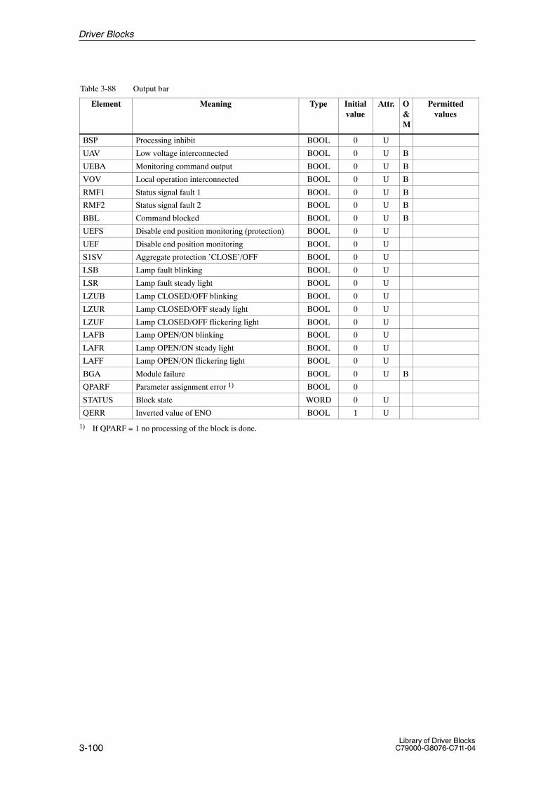
3-100Library of Driver Blocks
C79000-G8076-C711-04
Table 3-88 Output bar
Element Permittedvalues
O&M
Attr.Initialvalue
TypeMeaning
BSP Processing inhibit BOOL 0 U
UAV Low voltage interconnected BOOL 0 U B
UEBA Monitoring command output BOOL 0 U B
VOV Local operation interconnected BOOL 0 U B
RMF1 Status signal fault 1 BOOL 0 U B
RMF2 Status signal fault 2 BOOL 0 U B
BBL Command blocked BOOL 0 U B
UEFS Disable end position monitoring (protection) BOOL 0 U
UEF Disable end position monitoring BOOL 0 U
S1SV Aggregate protection ’CLOSE’/OFF BOOL 0 U
LSB Lamp fault blinking BOOL 0 U
LSR Lamp fault steady light BOOL 0 U
LZUB Lamp CLOSED/OFF blinking BOOL 0 U
LZUR Lamp CLOSED/OFF steady light BOOL 0 U
LZUF Lamp CLOSED/OFF flickering light BOOL 0 U
LAFB Lamp OPEN/ON blinking BOOL 0 U
LAFR Lamp OPEN/ON steady light BOOL 0 U
LAFF Lamp OPEN/ON flickering light BOOL 0 U
BGA Module failure BOOL 0 U B
QPARF Parameter assignment error 1) BOOL 0
STATUS Block state WORD 0 U
QERR Inverted value of ENO BOOL 1 U
1) If QPARF = 1 no processing of the block is done.
Driver Blocks

3-101Library of Driver BlocksC79000-G8076-C711-04
3.20 TM_RK Driver Block for Single-Channel Closed-Loop ControllerModules
FB 318
The instance of the driver block must be installed in OB100 (warm restart)and in OB102 (cold restart), in addition to its usual watchdog interrupt OB(for example OB32).
This driver block is used for the acquisition of signals from the TELE-PERM M single-channel controller modules 6DS1 400-8AA/-8BA (S-typecontroller) or 6DS1 401-8AA/-8BA (K-type controller) and for the transfer ofcommands and normalized increments to the controller module. The readsignals are presented at the block output.
The controller module transfers various groups of binary and analog signalsto the TM_RK block where they are presented as output signals. These si-gnals are:
– Fault alarms– Return data protective interlocking– Configuration jumpers– Analog values – Controller parameters– Mode return data.
The following groups of binary and analog signals from the RK block arerouted to the controller module:
– Mode selection– Protective commands, interlocking– Increments (Y, W, XD and V).
� Modes
In manual mode (H), the manipulated variable Y can be specified within theparameterized control limits (YHUG to YHOG) via the OS. The normalizedactuating increment Y = YH – WY is then transferred to the controller mo-dule.
In automatic mode (A), either setpoint W or ratio V (for ratio control) can bespecified within the parameterized control limits WUG/VUG and WOG/VOG, depending on the module input circuit (BAR1, EBR2, EBR3).
Ratio control: EBR1 = 0 and EBR2 = EBR3 = 1 Depending on the configuration jumper assignments, the appropriate norma-lized increment 0 to 100 is transferred to the controller module.
When controlling Y in manual mode or W and V in automatic mode via theOS, it should be noted that the respective value from the OS is only presentand effective for increment generation during one cycle (TA). During pro-gram execution the difference between the value entered and the currentlyeffective value is transferred as an increment to the module. The increment
Type/Number
Calling OBs
Function
Working Method
Driver Blocks

3-102Library of Driver Blocks
C79000-G8076-C711-04
will be 0 during the next cycle, as only the effective values WY, WXW, WWand WV, read from the module, will then be used for increment generation.
The analog value at input CE (= WC, VC or XDC (with SPC jumper) or YC(without SPC jumper)), related to the currently effective analog value WW,WV, WXW or WY, is used in C mode (compute) for increment generation.
If transition to C mode is possible, binary output BRBG = 1 (ready for Cmode).
When in SPC mode, input CE is monitored and limited to the parameterizedlimits YCU to YCO, if necessary. Although the input value is not modified,the delimited value is used for increment generation.
In H mode and active correction of manipulated variable YNF , the actuatoris corrected to the corrective manipulated variable YN. The actuator cannotbe controlled manually as long as the correction value of the manipulatedvariable is 1. The signal YNF must be reset to make possible manual opera-tion.
� Mode selection
The Modes H, A or C are selected either via the OS (binary inputs H, A andC) or via the unassigned binary inputs HBA, ABA and CBA. The unassignedinputs have a higher priority than the inputs from OS. The latter are only ef-fective if all three unassigned inputs have been reset.
� Parameterization
The module number is parameterized via input BGNR.The outputs DEA,DEZ,WEA,WEZ and S80,GO,GU of the K-type controller6DS1 401-8BA are insignificant.Outputs SPC, XDC, XDE, WE, WF and EBR1 to EBR3 (configuration jum-per status) and the outputs KP, TN, K1TV, K2K1, K3K2, K4K3, K5K4,K6K5 (controller parameters and parameters of the adjusters K1 to K6) areupdated either during initialization or after a transition to “manual mode”.
� Cycle
250 ms is the minimum processing cycle of the TM_RK block permitted forcommunication with the module.
� Limit value generation
The limits OG and UG of the effective system deviation WXW or the effec-tive controlled variable WX are monitored. The monitoring value is selectedby parameterizing input GWU. The result of the limit value check is fed tothe outputs GO and GU.
* STU = 0– GWU = 0
The effective system deviation WXW is used for limit value monitoring.A hysteresis of 1 % (OG–UG) is used when monitoring the limits OGand UG.
– GWU = 1The effective controlled variable WX is used for limit value monitoring.A hysteresis parameterized via input HYWX is considered when monitoring the limits OG and UG
Driver Blocks

3-103Library of Driver BlocksC79000-G8076-C711-04
* STU = 1– Monitoring is disabled and the outputs GO and GU are set = 0 gesetzt.
� Interlocking monitoring
The fault alarm „interlocking monitoring has responded” (S31) is not usedfor the error number generation. S31 is mapped at output S31 and displayedin the loop display on the OS during the monitoring time specified via inputUZT. If UZT = 0, interlocking is displayed for the duration of one cycle.
� Jumper assignments
Measuring span of effective (W) – andcentral unit(C) – values
Mode Mode indicator
SPC XDC VR
EBR 1 = 1 EBR 2 = 1 EBR 3 = 1
XD /XDE
WF �
��Y = Y – YWManual H = 1 X X X X / X X
Automatic A = 1 XX
XX
01
0 / 00 / 0
00
��W = W – WW��V = W – VW (W = V)
YHUG to YHOG
VWUG to VWOG
Compute C = 1 0 X X X / X 0 ��Y = CE – WY
C = 1A = 1
111
001
01X
X / XX / XX / X
000
��W = CE – WW��V = CE – VW� XD = CE – WXW
YCU to YCD
1 = jumper inserted0 = jumper not insertedX = not significant
Jumper assignment for increment generation
During processing the driver monitors both the hardware and the values.This results in the following error displays:
� QPARF = 1: Parameter assignment error (see startup characteristics)
� BGF = 1: This output indicates the module or the process valuesare not available. Possible causes:QVZ: Module time-out (incorrect address, incorrect
jumpers or module is defective),EANK:multiple addressing/acknowledge from modules
(incorrect jumper setting)
� ENO = 0: The operating system has recognized a general error byitself (e.g. overflow).
During a startup/initial run or parameter change all parameters are checkedfor permitted values. If the allowed limits are exceeded, the driver sets itsoutput QPARF = 1 and does not carry out any further processing in thesubsequent cycles, e.g. no I/O accesses are done and the outputs retain theirold values.
Error handling
StartupCharacteristics
Driver Blocks

3-104Library of Driver Blocks
C79000-G8076-C711-04
Time Response Does not exist. If the driver output values are needed from blocks with timeresponse (e.g. closed-loop control block) the driver has to be installed in thesame OB before this block.
Message Behavior Description of the message behaviorThe PCS 7 block ALARM_8P is used to generate control-system messages.
Table 3-89 Control-system messages of the TM_RK block
MessageNo.
Blockparameter
Initial start message text Messageclass
1 QPARF Parameter assignment error (F410) S
2 QCOM Communication error FM S
3 QVZ Module time-out (S305) S
4 EANK Multiple addressing (S313) S
5 S80 v S4 Module malfunction (S321) S
6
7 0 Control system message identifier
8 1 Control system message identifier
Table 3-90 Assignment of the accompanying values to the block parameters
Accompanying value Block parameter
1 BGNR
2 WAF
The UZT parameter is limited to the range 0 to 255 (without error message).
Status Transfer Description of the status word transfer.In order to transfer the status word, two PCS7 ALARM_8 system blocks arecalled. The two highest order bits contain a code, which is processed e.g. bythe associated OCX (display) block. This is necessary, because the assign-ment of the two status bytes to the WinCC variables EventRaw#x is not un-equivocal.
Driver Blocks
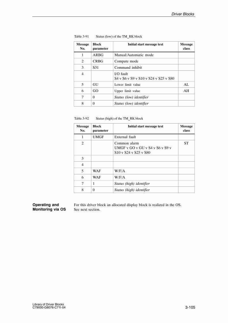
3-105Library of Driver BlocksC79000-G8076-C711-04
Table 3-91 Status (low) of the TM_RK block
MessageNo.
Blockparameter
Initial start message text Messageclass
1 ARBG Manual/Automatic mode
2 CRBG Compute mode
3 S31 Command inhibit
4 I/O faultS4 v S6 v S9 v S10 v S24 v S25 v S80
5 GU Lower limit value AL
6 GO Upper limit value AH
7 0 Status (low) identifier
8 0 Status (low) identifier
Table 3-92 Status (high) of the TM_RK block
MessageNo.
Blockparameter
Initial start message text Messageclass
1 UMGF External fault
2 Common alarmUMGF v GO v GU v S4 v S6 v S9 vS10 v S24 v S25 v S80
ST
3
4
5 WAF W/F/A
6 WAF W/F/A
7 1 Status (high) identifier
8 0 Status (high) identifier
For this driver block an allocated display block is realized in the OS.See next section.
Operating andMonitoring via OS
Driver Blocks

3-106Library of Driver Blocks
C79000-G8076-C711-04
The mode of the RK block – Manual/Automatic/Compute – can be changedby clicking on the highlighted area.The analog values W and Y can be changed by clicking on the mnemonicname or the allocated digital value.
(name of OCX: S7.G_RK resp. S7.K_RK)
Name Source / Input Operator-Controllable?1)
Technological name ATN noMnemonic name X TX noDigital display X WX noAnalog display X (bar) WX nomnemonic name W TW noDigital display W WW yes, via WAnalog display W (bar) WW yes, via WQuantity X, W EHTX noUpper limit display range X, W WXE noLower limit display range X, W WXA noUpper limit bar display OG noLower limit bar display UG noMnemonic name Y TY noDigital display Y WY yes, via YAnalog display Y (bar) WY yes, via YQuantity Y static noUpper limit display range Y YCO noLower limit display range Y YCU noDisplay range Y static noUpper range limit YCO noLower range limit YCU noManual mode H / state yesAutomatic mode A / state yesCompute mode C / state yesPCS fault (external fault) state noUpper limit digital display OG noLower limit digital display UG noUpper operating limit setpoint VWOG noLower operating limit setpoint VWUG noUpper operating limit manipulated vari-able
YHOG yes
Lower operating limit manipulated vari-able
YHUG yes
Proportional factor Kp KP noReset time TN noAdjuster constant K1/TV K1TV noAdjuster constant K2/K1 K2K1 noAdjuster constant K3/K2 K3K2 noAdjuster constant K4/K3 K4K3 noAdjuster constant K5/K4 K5K4 noAdjuster constant K6/K5 K6K5 noModule fault display WAF /Status Status no
1) May be restricted by input privilege
Standardized Dis-play for the RK block
Driver Blocks

3-107Library of Driver BlocksC79000-G8076-C711-04
The following two pictures show the RK block as a group and as a loop dis-play. The mnemonic names for X, W and Y are read from the correspondingS2 string parameters in the AS and entered in the display. The fault (tolerance) or warning / alarm representations are read from theWAF status and entered in the display. The group display shows the WAF status = fault (tolerance), in the loop dis-play the WAF status = Alarm is shown.
Figure 3-14 Group display of the TM_RK block
Driver Blocks

3-108Library of Driver Blocks
C79000-G8076-C711-04
Figure 3-15 Loop display of the TM_RK block
Driver Blocks

3-109Library of Driver BlocksC79000-G8076-C711-04
After klicking on the highlighted area W resp. Y the corresponding operationboxes are opened. They allow absolute or incremental adjustment of the va-lue. With incremental adjustment, a klick on the % buttons causes the OS totransfer the adjusted value to the AS immediately.
When klicking on the highlighted area Manual / Automatic /Compute thecorresponding operation box is opened. The actual mode is highlighted.When the desired mode has been klicked, that mode becomes highlighted.The operator intervention is concluded by a click on the OK button (transferof the command to the PLC) or by the Cancel button.
The operation boxes are always opened inside the OCX and cannot be movedoutside. For better clearness they are shown here without the OCX.
Operation box forW adjustment
Operation box forManual/Automatic/Compute adjustment
Operation box forY adjustment
Figure 3-16 Operation boxes of the TM_RK block
Operation boxes
Driver Blocks

3-110Library of Driver Blocks
C79000-G8076-C711-04
The following tables present the input and output bars of the block.
Table 3-93 Input bar
Element Meaning Type Initialvalue
Attr. O&M
Permittedvalues
CE Computer presetting YC, WC, VC, XDC REAL 0,0 Q
YN Correction input REAL 0,0 Q
YHOG Y manual upper limit REAL 105,0 Q B
YHUG Y manual lower limit REAL –5,0 Q B
VWOG Upper limit WH resp. VH REAL 100,0 Q B
VWUG Lower limit WH resp. VH REAL 0,0 Q B
X1E Upper range limit X1 REAL 100,0 Q
X1A Lower range limit X1 REAL 0,0 Q
X2E Upper range limit X2 REAL 100,0 Q
X2A Lower range limit X2 REAL 0,0 Q
X3E Upper range limit X3 REAL 100,0 Q
X3A Lower range limit X3 REAL 0,0 Q
WXE Upper range limit (WX,WW,WXW) REAL 100,0 Q B
WXA Lower range limit (WX,WW,WXW) REAL 0,0 Q B
OG Upper limit value for WX/WXW REAL 100,0 Q B
UG Lower limit value for WX/WXW REAL 0,0 Q B
HYWX Hysteresis f. XW lim.val.monitoring funct. REAL 0,0 Q
YCO Upper Y–DDC limit REAL 100,0 Q B
YCU Lower Y–DDC limit REAL 0,0 Q B
UZT Monitoring time for S31 display INT 10 Q 0...255
GWU Limit value switchover WX/WXW BOOL 0
STU Interference suppression GO/GU BOOL 0 Q
US Status output suppression BOOL 0 Q
UMGF S display environment fault external BOOL 0 Q
HBA Manual mode from central unit BOOL 0 Q
ABA Automatic mode from central unit BOOL 0 Q
CBA Compute mode from central unit BOOL 0 Q
YNF Y correction condition BOOL 0 Q
RSOF Controller inhibit OPEN BOOL 0 Q
RSSL Controller inhibit CLOSED BOOL 0 Q
SUOF Protection OPEN SKA BOOL 0 Q
SUSL Protection CLOSE SKZ BOOL 0 Q
BGNR Module number INT –1 0...60, 100...160
WAF Modul fault display INT 0 0, 1, 2
TY Mnemonic for Y STRING2 ’Y ’ U B
TW Mnemonic for W STRING2 ’W ’ U B
TX Mnemonic for X STRING2 ’X ’ U B
TH Mnemonic for H STRING2 ’H ’ U B
I/O Bars
Driver Blocks
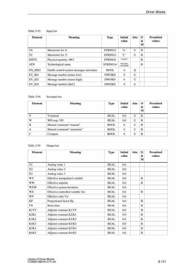
3-111Library of Driver BlocksC79000-G8076-C711-04
Table 3-93 Input bar
Element Permittedvalues
O&M
Attr.Initialvalue
TypeMeaning
TA Mnemonic for A STRING2 ’A ’ U B
TC Mnemonic for C STRING2 ’C ’ U B
EHTX Physical quantity AW1 STRING6 ’*EHTX*’ B
ATN Technological name STRING16 ‘*TECHNO-LOG.NAME*
B
EN_MSG Enable control-system messages and status BOOL 0 Q
EV_ID1 Message number (status low) DWORD 0 U
EV_ID2 Message number (status high) DWORD 0 U
EV_ID3 Message number (I&C) DWORD 0 U
Table 3-94 In/output bar
Element Meaning Type Initialvalue
Attr. O&M
Permittedvalues
Y Y-manual REAL 0,0 U B
W WH resp. VH REAL 0,0 U B
H Manual command “manual” BOOL 0 U B
A Manual command “automatic” BOOL 0 U B
C Compute BOOL 0 U B
Table 3-95 Output bar
Element Meaning Type Initialvalue
Attr. O&M
Permittedvalues
X1 Analog value 1 REAL 0,0
X2 Analog value 2 REAL 0,0
X3 Analog value 3 REAL 0,0
WY Effective manipulated variable REAL 0,0 B
WW Effective setpoint REAL 0,0 B
WXW Effective system deviation REAL 0,0
WX Effective controlled variable Xw REAL 0,0 B
WV Effective ratio Vw REAL 0,0
KP Proportional factor Kp REAL 0,0 B
TN Reset time REAL 0,0 B
K1TV Adjuster constant K1/TV REAL 0,0 B
K2K1 Adjuster constant K2/K1 REAL 0,0 B
K3K2 Adjuster constant K3/K2 REAL 0,0 B
K4K3 Adjuster constant K4/K3 REAL 0,0 B
K5K4 Adjuster constant K5/K4 REAL 0,0 B
K6K5 Adjuster constant K6/K5 REAL 0,0 B
Driver Blocks

3-112Library of Driver Blocks
C79000-G8076-C711-04
Table 3-95 Output bar
Element Permittedvalues
O&M
Attr.Initialvalue
TypeMeaning
HRBG Mode: Manual (RBG) BOOL 0
ARBG Mode: Automatic (RBG) BOOL 0
CRBG Mode: Compute (RBG) BOOL 0
BRBG Controller module ready BOOL 0
SPC Configuration jumper Setpoint Control BOOL 0
XDC Xd specification from central unit BOOL 0
XDE External system deviation BOOL 0
WE External setpoint W BOOL 0
WF Setpoint W from panel BOOL 0
EBR1 Configuration jumper input circuit BOOL 0
EBR2 Configuration jumper input circuit BOOL 0
EBR3 Configuration jumper input circuit BOOL 0
RSPO Controller inhibit OPEN BOOL 0
RSPS Controller inhibit CLOSE BOOL 0
SUO Protective command OPEN BOOL 0
SUS Protective command CLOSE BOOL 0
DEA Torque switch OPEN BOOL 0
DEZ Torque switch CLOSED BOOL 0
WEA Limit switch OPEN BOOL 0
WEZ Limit switch CLOSE BOOL 0
S4 Module malfunction BOOL 0 B
S6 Control station malfunction BOOL 0 B
S9 Analog signal monitoring /Common S91–S95 BOOL 0 B
S10 Binary signal monit. function has responded BOOL 0 B
S24 Motor temperature too high BOOL 0 B
S25 Power section malfunction BOOL 0 B
S31 Interlocking monitoring function has responded BOOL 0 B
S80 Module fault, read/cycle error BOOL 0 B
GO Upper limit violation BOOL 0
GU Lower limit violation BOOL 0
BGF Module fault QVZ or EANK BOOL 1
QPARF Parameter assignment error 1) BOOL 0
STATUS Block state WORD 0 U
QERR Inverted value of ENO BOOL 1 U
1) If QPARF = 1 no processing of the block is done.
Driver Blocks

3-113Library of Driver BlocksC79000-G8076-C711-04
3.21 TM_RZ ���������� ���������������������������
����
FB 319
The instance of the driver block must be installed in OB100 (warm restart)and in OB102 (cold restart), in addition to its usual watchdog interrupt OB(for example OB32).
This driver block is used for the acquisition of analog and binary signals viaone channel of a two-channel TELEPERM M controller module6DS1 402-8AA/-8BA or 6DS1 403-8AA/-8CA/-8CB. It is used together withthe TM_RZA block.
The block converts the analog and binary values into values of system-inter-nal representation. The controlled variable is present at the outputs RX1 andX1 as a root-extracted or as a non-root-extracted physical quantity within theparameterized range (X1A, X1E).
The current actuator position (YR) and controller setpoint (W) are output asphysical quantities via outputs YR (actuator position) and W (setpoint). YR ispresented between 0 and 100 %, W within the range (X1A, X1E). The modestates are issued via outputs H, A, C, N, SPC. Two analog values from unas-signed inputs (of the controller module) are present as physical quantitieswithin the measuring ranges (X2A, X2E, X3A, X3E) at outputs X2 and X3.
An additional binary value BW from an unassigned input (of the controllermodule) is issued at output BW. If an analog signal is outside the range, analarm is issued via output XF.If a double reading error occurs during analog signal acquisition (S 321) theold values remain unchanged.A malfunction of the controller module is signalled via the associated outputBGF. A control station malfunction is signalled via the associated outputLGF.The module number is parameterized via input BGNR, the channel numberon the module related to this TM_RZ block via input KNR.
� Configuration instructions
When implementing very fast DDC controls, the problem of systems oscilla-tion after a change in the setpoint could arise.To minimize the oscillations there are two alternatives for configuration:
1st alternative:After the Delta value has been calculated it may be divided by 4. This divi-sion causes the P component to be reduced to 25% of the original value.
2nd alternative:Insert the YR-jumper on the controller module.Install the TM_RZ (together with the block, which calculates the Delta va-lue), in an OB, which runs at double speed, compared to the OB containingthe TM_RZA block. The latter OB must have a phase displacement againstthe TM_RZ OB (e.g. TM_RZ OB = 250 ms, TM_RZA OB = 500 ms, displa-cement = 250 ms). In this configuration, using the YR jumper, the internal
Type/Number
Calling OBs
Function
Working Method
Driver Blocks

3-114Library of Driver Blocks
C79000-G8076-C711-04
filter on the controller module is disabled, in order to bridge the dead timesof the CPU / FM communication.
Reason:
The execution time between TM_RZ and TM_RZA block has the same effecton the closed-loop control circuit as a dead time. In addition, the values read by the TM_RZ block will be declared invalid(S321), if the test word written by the TM_RZA block cannot be processed inthe module before the TM_RZ block performs the next access. The executiontime of the 6DS1 402 or 6DS1 403 module cannot exceed 130 ms. Executionof a RZ block located at the beginning of a cycle (watchdog interrupt) fol-lows too quickly after the execution of the RZA block at the end of thewatchdog interrupt, if the watchdog interrupt has been restarted immediately.Even if there is sufficient time beween the end of a watchdog interrupt andthe start of the next watchdog interrupt in normal operation, this interval canbe reduced to nearly zero (delayed cycle start) if additional computer time isrequired temporarily by the same watchdog interrupt or by higher prioritywatchdog interrupts.
During processing the driver monitors both the hardware and the value.This results in the following error displays:
� QPARF = 1: Parameter assignment error (see startup characteristics)
� BGF = 1: This output indicates the module or the process valuesare not available. Possible causes:QVZ: Module time-out (incorrect address, incorrect
jumpers or module is defective),EANK:multiple addressing/acknowledge from modules
(incorrect jumper setting)
� ENO = 0: The operating system has recognized a general error byitself (e.g. overflow).
During a startup/initial run or parameter change all parameters are checkedfor permitted values. If the allowed limits are exceeded, the driver sets itsoutput QPARF = 1 and does not carry out any further processing in thesubsequent cycles, e.g. no I/O accesses are done and the outputs retain theirold values.
Time Response Does not exist. If the driver output values are needed from blocks with timeresponse (e.g. closed-loop control block) the driver has to be installed in thesame OB before this block.
Error handling
StartupCharacteristics
Driver Blocks

3-115Library of Driver BlocksC79000-G8076-C711-04
Message Behavior Description of the message behavior.The PCS 7 block ALARM_8P is used to generate control-system messages.
Table 3-96 Control-system messages of the TM_RZ block
MessageNo.
Blockparameter
Initial start message text Messageclass
1 QPARF Parameter assignment error (F410) S
2 QCOM Communication error FM S
3 QVZ Module time-out (S305) S
4 EANK Multiple addressing (S313) S
5 QBGF Module malfunction (S321) S
Table 3-97 Assignment of the accompanying values to the block parameters
Accompanying value Block parameter
1 BGNR
2 KNR
For this driver block no allocated display block is necessary in the OS.Instead of this the elements of the standard grafic library of WinCC can beused for display.
The following tables present the input and output bars of the block.
Table 3-98 Input bar
Element Meaning Type Initialvalue
Attr. O&M
Permittedvalues
X1E Upper range limit X1 REAL 100,0 Q
X1A Lower range limit X1 REAL 0,0 Q
X2E Upper range limit X2 REAL 100,0 Q
X2A Lower range limit X2 REAL 0,0 Q
X3E Upper range limit X3 REAL 100,0 Q
X3A Lower range limit X3 REAL 0,0 Q
BGNR Module number INT –1 0...60, 100...160
KNR Channel number INT 0 0...63
EN_MSG Enable control-system messages BOOL 0 Q
EV_ID Message number DWORD 0 U
Operating andMonitoring via OS
I/O Bars
Driver Blocks

3-116Library of Driver Blocks
C79000-G8076-C711-04
Table 3-99 Output bar
Element Meaning Type Initialvalue
Attr. O&M
Permittedvalues
RX1 Root extracted controlled variable REAL 0,0
X1 Controlled variable REAL 0,0
X2 Analog value 1 REAL 0,0
X3 Analog value 2 REAL 0,0
YR Actuator position 2) REAL 0,0
W Setpoint of module REAL 0,0
H Manual BOOL 0
A Automatic BOOL 0
C Compute BOOL 0
N Correction external controller BOOL 0
SPC 1=SPC / 0=DDC BOOL 0
BW Binary value BOOL 0
XF Channel fault BOOL 1
BGF Module fault BOOL 1
LGF Control station fault BOOL 1
QPARF Parameter assignment error 1) BOOL 0
STATUS Block state WORD 0 U
QERR Inverted value of ENO BOOL 1 U
1) If QPARF = 1 no processing of the block is done.2) The manipulated variable is fed back if a controller module with continious output (i.e. 6DS1403-8CA) is used.
Driver Blocks

3-117Library of Driver BlocksC79000-G8076-C711-04
3.22 TM_RZA ����������� ��������������������������
����
FB 320
The instance of the driver block must be installed in OB100 (warm restart)and in OB102 (cold restart), in addition to its usual watchdog interrupt OB(for example OB32).
TM_RZA is used for transferring the setpoint increment W resp. the actua-ting increment Y, which normally comes from a controller block, to a chan-nel of a TELEPERM M controller module 6DS1 402-8AA/-8BA or6DS1 403-8AA/-8CA/-8CB. It is used together with the TM_RZ block.
The block transfers a normalized increment present at input DC (= setpointincrement W for SPC mode, actuating increment Y for DDC mode) to the controller module. The highest resolution is 0.1 %.
Input SPDC has the following functions:
- DDC mode (without SPC jumper)SPDC = 0: Controller inhibit is effective, after analog signal
monitoring has respondedSPDC = 1: Controller inhibit is not effective, after analog signal
monitoring has responded.Manual adjustment is possible.
- SPC mode (SPC jumper inserted)SPDC = 0: SPC modeSPDC = 1: Compute/manual mode. Controller inhibit is not
effective after analog signal monitoring has responded.
An additional unassigned binary value (BW) is transferred to the controllermodule via input BW. The module number is parameterized via input BGNR.The channel number related to the TM_RZA block is set via input KNR.
BGF is set = 1 if a hardware failure occurs (QVZ, EANK, cycle time-out).
� Cycle
250 ms is the minimum processing cycle of the RZ/RZA blocks permitted forcommunication with the module.
� Configuration instructions: see TM_RZ block
Type/Number
Calling OBs
Function
Working Method
Driver Blocks

3-118Library of Driver Blocks
C79000-G8076-C711-04
During processing the driver monitors both the hardware and the values.This results in the following error displays:
� QPARF = 1: Parameter assignment error (see startup characteristics)
� BGF = 1: This output indicates the module or the process valuesare not available. Possible causes:QVZ: Module time-out (incorrect address, incorrect
jumpers or module is defective),EANK:multiple addressing/acknowledge from modules
(incorrect jumper setting)
� ENO = 0: The operating system has recognized a general error byitself (e.g. overflow).
During a startup/initial run or parameter change all parameters are checkedfor permitted values. If the allowed limits are exceeded, the driver sets itsoutput QPARF = 1 and does not carry out any further processing in thesubsequent cycles, e.g. no I/O accesses are done and the outputs retain theirold values.
Time Response Does not exist. If the driver output values are needed from blocks with timeresponse (e.g. closed-loop control block) the driver has to be installed in thesame OB before this block.
Message Behavior Description of the message behavior.The PCS 7 block ALARM_8P is used to generate control-system messages.
Table 3-100 Control-system messages of the TM_RZA block
MessageNo.
Blockparameter
Initial start message text Messageclass
1 QPARF Parameter assignment error (F410) S
2 QCOM Communication error FM S
3 QVZ Module time-out (S305) S
4 EANK Multiple addressing (S313) S
Table 3-101 Assignment of the accompanying values to the block parameters
Accompanying value Block parameter
1 BGNR
2 KNR
Error handling
StartupCharacteristics
Driver Blocks
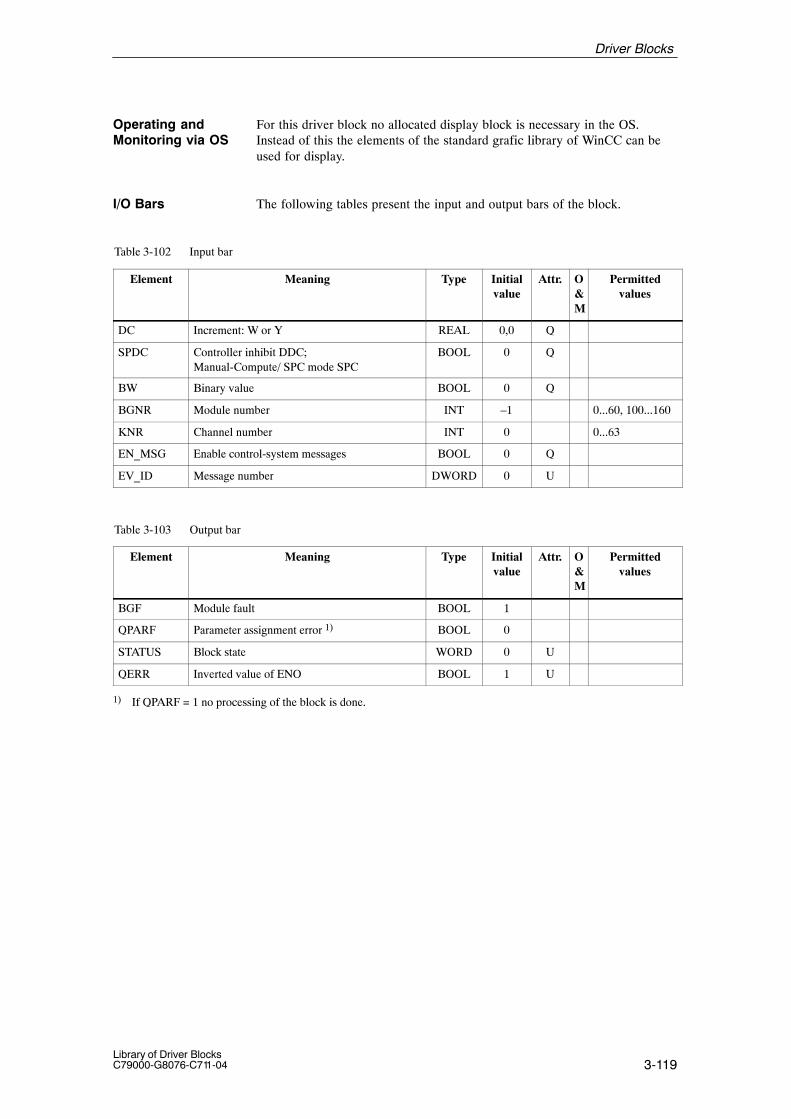
3-119Library of Driver BlocksC79000-G8076-C711-04
For this driver block no allocated display block is necessary in the OS.Instead of this the elements of the standard grafic library of WinCC can beused for display.
The following tables present the input and output bars of the block.
Table 3-102 Input bar
Element Meaning Type Initialvalue
Attr. O&M
Permittedvalues
DC Increment: W or Y REAL 0,0 Q
SPDC Controller inhibit DDC; Manual-Compute/ SPC mode SPC
BOOL 0 Q
BW Binary value BOOL 0 Q
BGNR Module number INT –1 0...60, 100...160
KNR Channel number INT 0 0...63
EN_MSG Enable control-system messages BOOL 0 Q
EV_ID Message number DWORD 0 U
Table 3-103 Output bar
Element Meaning Type Initialvalue
Attr. O&M
Permittedvalues
BGF Module fault BOOL 1
QPARF Parameter assignment error 1) BOOL 0
STATUS Block state WORD 0 U
QERR Inverted value of ENO BOOL 1 U
1) If QPARF = 1 no processing of the block is done.
Operating andMonitoring via OS
I/O Bars
Driver Blocks

3-120Library of Driver BlocksC79000-G8076-C711-04
3.23 TM_S5KE, 3964(R) Linking Receiver Block
FB 321
The instance of the driver block must be installed in OB100 (warm restart)and in OB102 (cold restart), in addition to its usual watchdog interrupt OB(for example OB32).
TM_S5KE receives message frames from another automation system via aTELEPERM M Interface module and stores the data in a S7 data block.Usually it is used together with one ore more TM_S5KS blocks.
This driver block is used to receive message frames from automation systemsSIMATIC S5--135U, S5--155U and S5--155H, S7--300, S7--400 and other sy-stems using RK512, 3964/ 3964R protocols via one of the TELEPERM Minterface modules 6DS1 333-8AB, 6DS1 318-8AB. In addition, user pro-grammable modules based on 6DS1328-8AA hardware allow linking to otherprotocols, if their transfer RAM drivers are compatible with S5KS/S5KEhandshake.
Notice
One driver is normally sufficient for each interface module. If various driverblocks are specified, they must be installed in the same processing cycle.Proper monitoring and fault processing require the block to be embedded ina processing cycle of ≥ 1 s.
S Parameters and their meaning
The module’s receive buffer length is 12 message frames (each with128 bytes net data) for 2-channel operation.
The module number is parameterized via input BGNR.
It can be set to a value between 0 and 60 (base unit) or 100 to 160 (extensionunit).
Driver output BGF is set if an incorrect module number is selected on themodule or in the driver block or if more than one module respond to the sameBGNR.
S Monitoring of the interface unit in TELEPERM M
The driver block monitors the interface module cyclically. An error message(STOE = 1) is issued if the module does not acknowledge. In addition, themodule monitors the driver block for detecting a failure in the AS system.
S Transmitter configuration in SIMATIC S5
Five parameters are transferred from SIMATIC S5 to the receiver block ineach message frame header. The length of the message frame header is 10Bytes (Bytes 1 and 2 always contain 00H).
Type/Number
Calling OBs
Function
Working Method
Driver Blocks

3-121Library of Driver BlocksC79000-G8076-C711-04
Note:
All blocks must be 256 words long.
Specification of the message frame header data from SIMATIC S5:
– Type of instruction (byte 3 and 4 of S5 message frame)The driver block only recognizes the identifier ”AD” (= data out in-struction).
– AS target address (byte 5 and 6 of S5 message frame)The data received is stored in a DB for further processing / intercon-nection. Byte 5 contains the DB no., Byte 6 the element number wherethe data is to be stored. 1)
Condition: Block length = 256 (mandatory)
– Number of data (bytes 7 and 8 of S5 message frame). This value is always specified in data words (1 word = 2 bytes = 16 bits).
– Code for data type / coordination flag (bytes 9 and 10 of S5 messageframe).
– There is only one data type in each message frame. The code corres-ponds to the co-ordination flag bit in byte 10 (see table 3–90). Flag byte 9 is not interpreted, but must, however, differ from zero, asotherwise bytes 9 and 10 of the message frame from the CP525 willcontain FFH.
Table 3-104 Data types
Data type ( S5 ) Code Unit Max. number/values per receive job
�����$��� 0 16 values �'()
"*����� �$����+�,�- . 1 ��$��� ,)
"��� ������ �$���+/(�- . 2 ��$��� /(
�����$�����0����
+�������1���'2�-� �-��
���0����� 0��-�� 0�.
3 16 values �'()
– Data (follows immediately after the message frame header, byte 11 upto 138). Up to 128 bytes can be used in a receive job (message frame)for data transfer.
1) Target DB no. = (DB no. in GAGB parameter) + ( No. in message frame). The target DB must exist and must be long enough.
Driver Blocks

3-122Library of Driver Blocks
C79000-G8076-C711-04
� Fault processing
The following outputs are set for fault detection:
BGF Module fault (Hardware)Reaction: Execution is aborted, S 305
STOE Module failure (Software)– Self-detection by interface module – Monitoring has respondedReaction: Execution is aborted
PAF1, PAF2 The partner connected to channel 1 or channel 2 respectively is defective (USART fault at interface 1/2, e.g. incorrect baud rate, parity, frame or overrun error). Reaction: None
KF1, KF2 There is a fault in the link between partner 1/2 and the interface module (line fault at interface 1/2, e.g. charactertime-out 220ms, acknowledgement time-out 550 ms, returnmessage time-out 5 s, checksum error BCC 3964R after 5repetitions, open-circuit).Reaction: S387
STF Configuration fault– Target block cannot be found– Target block too shortReaction: Message frame is rejected, processing aborted.The no. of the errouneous DB (without base) can be read atoutput ”FBST”.
EPU Receive buffer overflowReaction: Execution is continued.
The last message is rejected by the interface module if buffer processing does not continue after a waiting time.
Remedy: Check processing cycle
Note:
KF and PAF are not set in message-specific manner, they are indicated in alldrivers accessing the module during the error bit output (no error interpreta-tion related to the transmitter block).
Driver Blocks
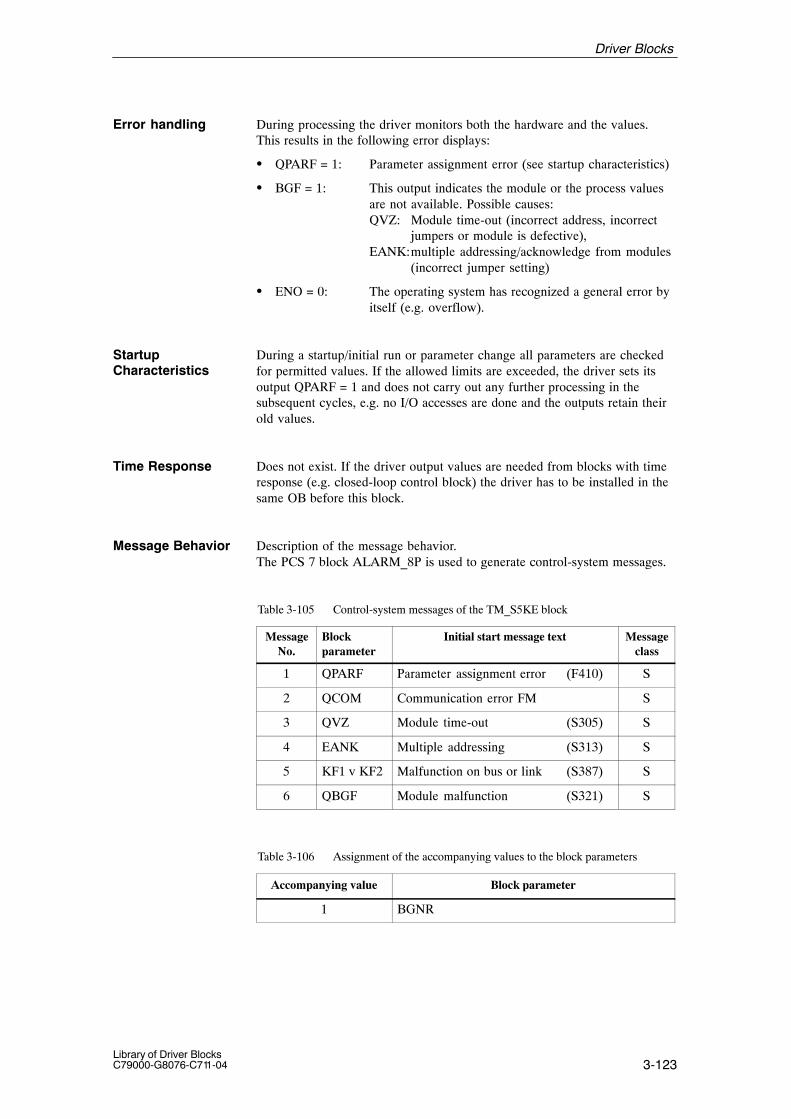
3-123Library of Driver BlocksC79000-G8076-C711-04
During processing the driver monitors both the hardware and the values.This results in the following error displays:
� QPARF = 1: Parameter assignment error (see startup characteristics)
� BGF = 1: This output indicates the module or the process valuesare not available. Possible causes:QVZ: Module time-out (incorrect address, incorrect
jumpers or module is defective),EANK:multiple addressing/acknowledge from modules
(incorrect jumper setting)
� ENO = 0: The operating system has recognized a general error byitself (e.g. overflow).
During a startup/initial run or parameter change all parameters are checkedfor permitted values. If the allowed limits are exceeded, the driver sets itsoutput QPARF = 1 and does not carry out any further processing in thesubsequent cycles, e.g. no I/O accesses are done and the outputs retain theirold values.
Time Response Does not exist. If the driver output values are needed from blocks with timeresponse (e.g. closed-loop control block) the driver has to be installed in thesame OB before this block.
Message Behavior Description of the message behavior.The PCS 7 block ALARM_8P is used to generate control-system messages.
Table 3-105 Control-system messages of the TM_S5KE block
MessageNo.
Blockparameter
Initial start message text Messageclass
1 QPARF Parameter assignment error (F410) S
2 QCOM Communication error FM S
3 QVZ Module time-out (S305) S
4 EANK Multiple addressing (S313) S
5 KF1 v KF2 Malfunction on bus or link (S387) S
6 QBGF Module malfunction (S321) S
Table 3-106 Assignment of the accompanying values to the block parameters
Accompanying value Block parameter
1 BGNR
Error handling
StartupCharacteristics
Driver Blocks
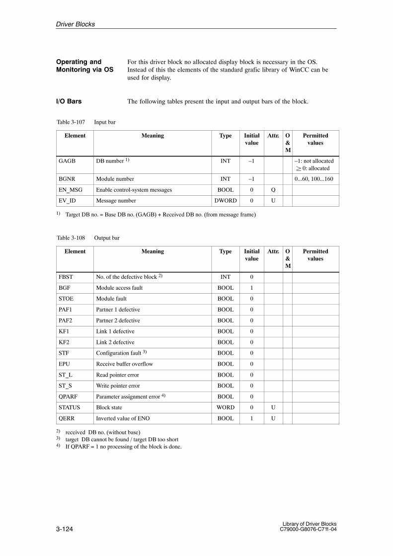
3-124Library of Driver Blocks
C79000-G8076-C711-04
For this driver block no allocated display block is necessary in the OS.Instead of this the elements of the standard grafic library of WinCC can beused for display.
The following tables present the input and output bars of the block.
Table 3-107 Input bar
Element Meaning Type Initialvalue
Attr. O&M
Permittedvalues
GAGB DB number 1) INT –1 –1: not allocated � 0: allocated
BGNR Module number INT –1 0...60, 100...160
EN_MSG Enable control-system messages BOOL 0 Q
EV_ID Message number DWORD 0 U
1) Target DB no. = Base DB no. (GAGB) + Received DB no. (from message frame)
Table 3-108 Output bar
Element Meaning Type Initialvalue
Attr. O&M
Permittedvalues
FBST No. of the defective block 2) INT 0
BGF Module access fault BOOL 1
STOE Module fault BOOL 0
PAF1 Partner 1 defective BOOL 0
PAF2 Partner 2 defective BOOL 0
KF1 Link 1 defective BOOL 0
KF2 Link 2 defective BOOL 0
STF Configuration fault 3) BOOL 0
EPU Receive buffer overflow BOOL 0
ST_L Read pointer error BOOL 0
ST_S Write pointer error BOOL 0
QPARF Parameter assignment error 4) BOOL 0
STATUS Block state WORD 0 U
QERR Inverted value of ENO BOOL 1 U
2) received DB no. (without base)3) target DB cannot be found / target DB too short4) If QPARF = 1 no processing of the block is done.
Operating andMonitoring via OS
I/O Bars
Driver Blocks

3-125Library of Driver BlocksC79000-G8076-C711-04
3.24 TM_S5KS 3964(R) Linking Transmitter Block
FB 322
The instance of the driver block must be installed in OB100 (warm restart)and in OB102 (cold restart), in addition to its usual watchdog interrupt OB(for example OB32).
TM_S5KS transmits data from a S7 data block to another automation systemor initiates a data transfer in the opposite direction via a TM Interface modu-le. It is used together with a TM_S5KE block.
This driver block is used for transferring message frames to automation sy-stems SIMATIC S5–135U, S5–155U and S5–155H, S7–300, S7–400 andother systems using RK512, 3964 / 3964R protocols via one of the TELE-PERM M interface modules 6DS1 333-8AB, 6DS1 318-8AB. In addition,user programmable modules based on 6DS1328-8AA hardware allow linkingto other protocols, if their transfer RAM drivers are compatible with S5KS/S5KE handshake.The message frames transmitted contain either an inputcommand (ED) or an output command (AD). The input command fetchesdata from the partner (e.g. S5), the output command writes data to the part-ner.
� Parameters and their meaning
A driver block must be specified for each message frame. The blocks areenabled via input FSE = 1.
The module number is parameterized via input BGNR.
It can be set to a value between 0 and 60 (base unit) or 100 to 160 (extensionunit).
Driver output BGF is set if an incorrect module number is selected on themodule or in the driver block or if more then one module repsond to the sameBGNR.
The channel number (1 or 2) is selected via input KNR. Single- or two-chan-nel operation is possible.
KNR = 1 Message frame transfer to partner 1 onlyKNR = 2 Partner 2 exists: Message frame transfer also to partner 2.
No partner 2: Message frame transfer only to partner 1.Transfer occurs only after all messages defined by KNR = 1have been processed. This facilitates priority.controlled execution of transmission requests.
� Description of functions
The user generates the data structure by specifying data type, number andsource/target address.
Type/Number
Calling OBs
Function
Working Method
Driver Blocks
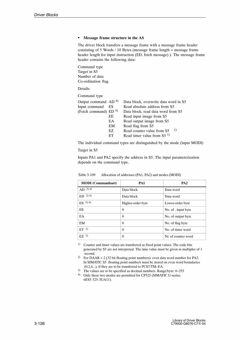
3-126Library of Driver Blocks
C79000-G8076-C711-04
� Message frame structure in the AS
The driver block transfers a message frame with a message frame headerconsisting of 5 Words / 10 Bytes (message frame length = message frameheader length for input instruction (ED, fetch message) ). The message frameheader contains the following data:
Command typeTarget in S5Number of dataCo-ordination flag.
Details:
Command type
Output command AD 4) Data block, overwrite data word in S5Input command ES Read absolute address from S5(Fetch command) ED 4) Data block, read data word from S5
EE Read input image from S5EA Read output image from S5EM Read flag from S5EZ Read counter value from S5 1)
ET Read timer value from S5 1)
The individual command types are distinguished by the mode (input MODI)
Target in S5
Inputs PA1 and PA2 specify the address in S5. The input parameterizationdepends on the command type.
Table 3-109 Allocation of addresses (PA1, PA2) and modes (MODI)
MODI (Commandsart) PA1 PA2
AD 2) 4) Data block Data word
ED 2) 4) Data block Data word
ES 3) 4) Higher-order byte Lower-order byte
EE 0 No. of . input byte
EA 0 No. of output byte
EM 0 No. of flag byte
ET 1) 0 No. of timer word
EZ 1) 0 Nr. of counter word
1) Counter and timer values are transferred as fixed point values. The code bitsgenerated by S5 are not interpreted. The time value must be given in multiples of 1 second.
2) For DAAR = 2 (32 bit floating point numbers): even data word number for PA2.In SIMATIC S5 floating point numbers must be stored on even word boundaries (0,2,4...), if they are to be transferred to PCS7/TM–EA.
3) The values are to be specified as decimal numbers. Range/byte: 0–2554) Only these two modes are permitted for CP525 (SIMATIC U-series,
6ES5 525-3UA11).
Driver Blocks
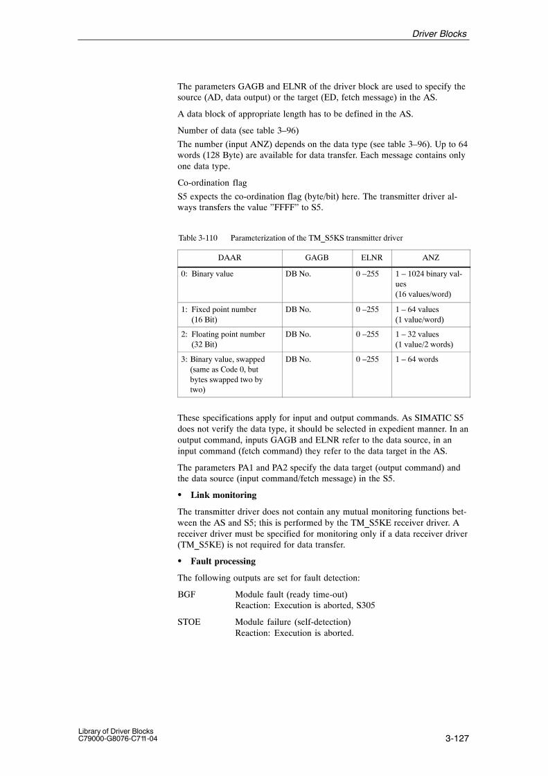
3-127Library of Driver BlocksC79000-G8076-C711-04
The parameters GAGB and ELNR of the driver block are used to specify thesource (AD, data output) or the target (ED, fetch message) in the AS.
A data block of appropriate length has to be defined in the AS.
Number of data (see table 3–96)
The number (input ANZ) depends on the data type (see table 3–96). Up to 64words (128 Byte) are available for data transfer. Each message contains onlyone data type.
Co-ordination flag
S5 expects the co-ordination flag (byte/bit) here. The transmitter driver al-ways transfers the value ”FFFF” to S5.
Table 3-110 Parameterization of the TM_S5KS transmitter driver
DAAR GAGB ELNR ANZ
0: Binary value DB No. 0 –255 1 – 1024 binary val-ues(16 values/word)
1: Fixed point number (16 Bit)
DB No. 0 –255 1 – 64 values(1 value/word)
2: Floating point number (32 Bit)
DB No. 0 –255 1 – 32 values (1 value/2 words)
3: Binary value, swapped(same as Code 0, but bytes swapped two bytwo)
DB No. 0 –255 1 – 64 words
These specifications apply for input and output commands. As SIMATIC S5does not verify the data type, it should be selected in expedient manner. In anoutput command, inputs GAGB and ELNR refer to the data source, in aninput command (fetch command) they refer to the data target in the AS.
The parameters PA1 and PA2 specify the data target (output command) andthe data source (input command/fetch message) in the S5.
� Link monitoring
The transmitter driver does not contain any mutual monitoring functions bet-ween the AS and S5; this is performed by the TM_S5KE receiver driver. Areceiver driver must be specified for monitoring only if a data receiver driver(TM_S5KE) is not required for data transfer.
� Fault processing
The following outputs are set for fault detection:
BGF Module fault (ready time-out)Reaction: Execution is aborted, S305
STOE Module failure (self-detection)Reaction: Execution is aborted.
Driver Blocks

3-128Library of Driver Blocks
C79000-G8076-C711-04
KAFE Second channel is missing (is set if the jumper has been configured for single-channel operation and channel 2 hasbeen addressed by the TM_S5KS block) Reaction: Error message when the second channel is
addressed. Message frames are transferred to channel 1 (only after all message frames from the buffer have been transferred there (priority depen-dent transmission).
KF1, KF2 There is a fault in the link between partner 1/2 and the interface module (line fault at interface 1/2, e.g. charactertime-out 220ms, acknowledgement time-out 550 ms, returnmessage time-out 5 s, checksum error BCC 3964R after 5repetitions, open-circuit).Reaction: S387; The message frame is transferred to the
interface module
PAF1, PAF2 The partner connected to channel 1 or channel 2 respectively is defective (USART fault at interface 1/2, e.g.incorrect baud rate, parity, frame or overrun error). Reaction: The message frame is transferred to the interface module.
STF Configuration fault1.Incorrect definition of DB block:
– Source block cannot be found– Source block too short
2.Incorrect parameterization of transmitter driver– Incorrect number of data
(floating point numbers: ANZ >32)3 Fixed point overflow
Range of fixed point number to be transferred has beenexceeded
. Reaction: Execution is aborted.
TF1, TF2 Message frame fault: S5 at channel 1 or channel 2 resp. hasnot accepted the last message frame (an error number was contained in the reaction message frame).Reaction: None
SPU1, SPU2 Transmit buffer overflow on interface module (channel 1 or channel 2 resp.)Reaction: Execution is aborted until the overflow bit in the
concerned channel has been cleared. No messageframes are transferred as long as the overflow bit isset.
Note:
KF and PAF are not set in message-specific manner, they are indicated in alldrivers accessing the module during the error bit output (no error interpreta-tion related to the transmitter block).
Output TF is only displayed by the driver block accessing first, as the driverresets the bit in the dual port RAM.
Driver Blocks
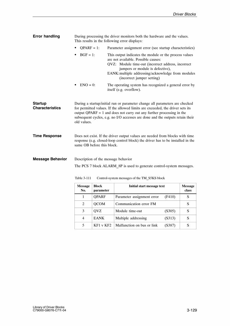
3-129Library of Driver BlocksC79000-G8076-C711-04
During processing the driver monitors both the hardware and the values.This results in the following error displays:
� QPARF = 1: Parameter assignment error (see startup characteristics)
� BGF = 1: This output indicates the module or the process valuesare not available. Possible causes:QVZ: Module time-out (incorrect address, incorrect
jumpers or module is defective),EANK:multiple addressing/acknowledge from modules
(incorrect jumper setting)
� ENO = 0: The operating system has recognized a general error byitself (e.g. overflow).
During a startup/initial run or parameter change all parameters are checkedfor permitted values. If the allowed limits are exceeded, the driver sets itsoutput QPARF = 1 and does not carry out any further processing in thesubsequent cycles, e.g. no I/O accesses are done and the outputs retain theirold values.
Time Response Does not exist. If the driver output values are needed from blocks with timeresponse (e.g. closed-loop control block) the driver has to be installed in thesame OB before this block.
Message Behavior Description of the message behavior
The PCS 7 block ALARM_8P is used to generate control-system messages.
Table 3-111 Control-system messages of the TM_S5KS block
MessageNo.
Blockparameter
Initial start message text Messageclass
1 QPARF Parameter assignment error (F410) S
2 QCOM Communication error FM S
3 QVZ Module time-out (S305) S
4 EANK Multiple addressing (S313) S
5 KF1 v KF2 Malfunction on bus or link (S387) S
Error handling
StartupCharacteristics
Driver Blocks

3-130Library of Driver Blocks
C79000-G8076-C711-04
Table 3-112 Assignment of the accompanying values to the block parameters
Accompanying value Block parameter
1 BGNR
2 KNR
3 DAAR
4 ELNR
5 ANZ
6 MODI
7 PA1
8 PA2
For this driver block no allocated display block is necessary in the OS.Instead of this the elements of the standard grafic library of WinCC can beused for display.
The following tables present the input and output bars of the block.
Table 3-113 Input bar
Element Meaning Type Initialvalue
Attr. O&M
Permittedvalues
FSE Transmitter enable BOOL 0 Q
BGNR Module number INT –1 0...60, 100...160
KNR Channel number INT 1 1, 2
DAAR Data type INT 0 0, 1, 2, 3
GAGB Data block no. (DB no.) in PCS 7 INT –1 � 0; with MODI<> ’AD’ max. 254
ELNR Element number (word offset in the DB) INT 0 � 0; with MODI<> ’AD’ max. 254
ANZ Number of data (in words) INT 1 1...32, 1...64
PA1 Partner address 1 INT 0 0...255
PA2 Partner address 2 INT 0 0...255
MODI Command mode STRING2 ’AD’ AD, ES, ED, EE,EA, EM, EZ, ET
EN_MSG Enable control-system messages BOOL 0 Q
EV_ID Message number DWORD 0 U
Operating andMonitoring via OS
I/O Bars
Driver Blocks

3-131Library of Driver BlocksC79000-G8076-C711-04
Table 3-114 Output bar
Element Meaning Type Initialvalue
Attr. O&M
Permittedvalues
BGF Module access fault BOOL 1
STOE Module fault BOOL 0
PAF1 Partner 1 defective BOOL 0
PAF2 Partner 2 defective BOOL 0
KF1 Link 1 defective BOOL 0
KF2 Link 2 defective BOOL 0
KAFE Channel 2 missing BOOL 0
TF1 Message frame fault 1 BOOL 0
TF2 Message frame fault 2 BOOL 0
STF Configuration fault 1) BOOL 0
SPU1 Transmit buffer 1 overflow BOOL 0
SPU2 Transmit buffer 2 overflow BOOL 0
ST_L Read pointer error BOOL 0
ST_S Write pointer error BOOL 0
QPARF Parameter assignment error BOOL 0
STATUS Block state WORD 0 U
QERR Inverted value of ENO BOOL 1 U
1) source DB cannot be found / source DB too short / fixed point overflow
Driver Blocks
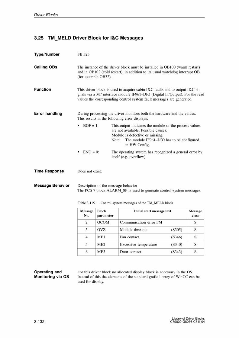
3-132Library of Driver Blocks
C79000-G8076-C711-04
3.25 TM_MELD Driver Block for I&C Messages
FB 323
The instance of the driver block must be installed in OB100 (warm restart)and in OB102 (cold restart), in addition to its usual watchdog interrupt OB(for example OB32).
This driver block is used to acquire cabin I&C faults and to output I&C si-gnals via a M7 interface module IF961–DIO (Digital In/Output). For the readvalues the corresponding control system fault messages are generated.
During processing the driver monitors both the hardware and the values.This results in the following error displays:
� BGF = 1: This output indicates the module or the process valuesare not available. Possible causes:Module is defective or missing.Note: The module IF961–DIO has to be configured
in HW Config.
� ENO = 0: The operating system has recognized a general error byitself (e.g. overflow).
Time Response Does not exist.
Message Behavior Description of the message behaviorThe PCS 7 block ALARM_8P is used to generate control-system messages.
Table 3-115 Control-system messages of the TM_MELD block
MessageNo.
Blockparameter
Initial start message text Messageclass
2 QCOM Communication error FM S
3 QVZ Module time-out (S305) S
4 ME1 Fan contact (S346) S
5 ME2 Excessive temperature (S340) S
6 ME3 Door contact (S343) S
For this driver block no allocated display block is necessary in the OS.Instead of this the elements of the standard grafic library of WinCC can beused for display.
Type/Number
Calling OBs
Function
Error handling
Operating andMonitoring via OS
Driver Blocks
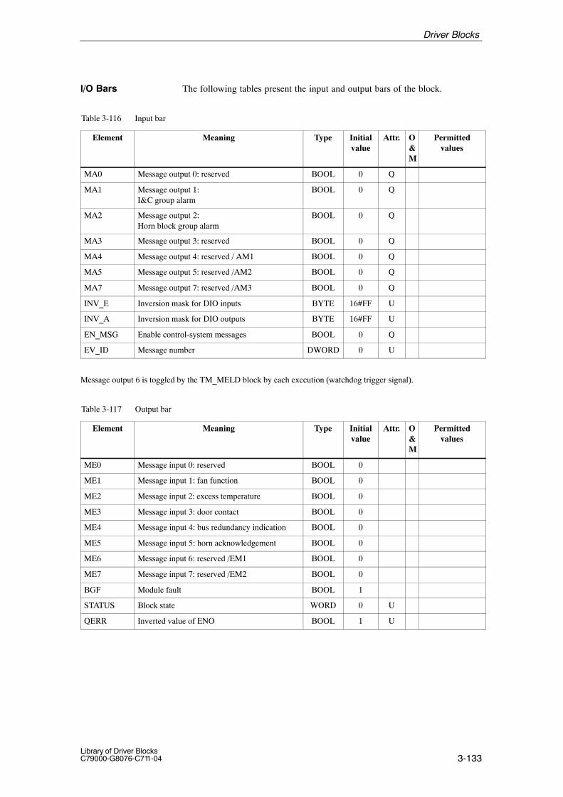
3-133Library of Driver BlocksC79000-G8076-C711-04
The following tables present the input and output bars of the block.
Table 3-116 Input bar
Element Meaning Type Initialvalue
Attr. O&M
Permittedvalues
MA0 Message output 0: reserved BOOL 0 Q
MA1 Message output 1:I&C group alarm
BOOL 0 Q
MA2 Message output 2:Horn block group alarm
BOOL 0 Q
MA3 Message output 3: reserved BOOL 0 Q
MA4 Message output 4: reserved / AM1 BOOL 0 Q
MA5 Message output 5: reserved /AM2 BOOL 0 Q
MA7 Message output 7: reserved /AM3 BOOL 0 Q
INV_E Inversion mask for DIO inputs BYTE 16#FF U
INV_A Inversion mask for DIO outputs BYTE 16#FF U
EN_MSG Enable control-system messages BOOL 0 Q
EV_ID Message number DWORD 0 U
Message output 6 is toggled by the TM_MELD block by each execution (watchdog trigger signal).
Table 3-117 Output bar
Element Meaning Type Initialvalue
Attr. O&M
Permittedvalues
ME0 Message input 0: reserved BOOL 0
ME1 Message input 1: fan function BOOL 0
ME2 Message input 2: excess temperature BOOL 0
ME3 Message input 3: door contact BOOL 0
ME4 Message input 4: bus redundancy indication BOOL 0
ME5 Message input 5: horn acknowledgement BOOL 0
ME6 Message input 6: reserved /EM1 BOOL 0
ME7 Message input 7: reserved /EM2 BOOL 0
BGF Module fault BOOL 1
STATUS Block state WORD 0 U
QERR Inverted value of ENO BOOL 1 U
I/O Bars
Driver Blocks

3-134Library of Driver Blocks
C79000-G8076-C711-04
Driver Blocks

4-1Library of Driver BlocksC79000-G8076-C711-04
Communication
This chapter describes the communication blocks.
The individual subjects are described on the following pages:
Abschnitt Thema Seite
4.1 Overview 4–2
4.2 Deployment of the Communication Blocks 4–3
4.3 TM_KOM Communication Block 4–4
4.4 TM_KST Communication Function 4–6
4.5 Configuration of the Connections 4–7
4.6 Other Configuration Informations 4–8
4.7 Data of the Group Interrupt Module 4–9
4.8 Error Messages of the FM456 (Communication) 4–10
4.9 Status Word of the Driver Blocks 4–11
Description of thisChapter
In this Chapter
4
4-2Library of Driver Blocks
C79000-G8076-C711-04
4.1 Overview
The process values to and from the TELEPERM I/O peripherals are transfer-red between the S7 CPU and the FM456 via the K bus. For this the connec-tions are used, that are configured on both sides. They allow the transfer ofdata packets of up to 64 Kbytes.
In order to minimize the number of connections and the required ressourcesof the CPU for the communication of the I/O driver blocks, the communica-tion of all I/O drivers, which are allocated to a watchdog interrupt, is proces-sed by two special communication blocks. These two blocks, TM_KST andTM_KOM, must be parameterized and added to the watchdog interrupt OBs.
Communication

4-3Library of Driver BlocksC79000-G8076-C711-04
4.2 Deployment of the Communication Blocks
For each watchdog interrupt OB3x, for which TELEPERM I/O drivers areneeded, the following configuration steps are required:
� The TM_KST FC has to be called before the first TM I/O driver. TheTM_KOM FB has to be called behind the last TM I/O driver.
� A S7connection between the S7 CPU and the FM456 has to be configuredwith the SIMATIC manager .The resulting assigned unique identifier mustbe entered at the C_ID input of the TM_KOM communication block.
� A global data block has to be reserved. Its number has to be input to theTM_KST and TM_KOM communication blocks. The communicationblocks themselves create these data blocks. They are used for transmitteddata, received data and for administration.
Example for a block sequence in the OB35:
FB NN1FB NN2..FB NNmFC TM_KSTFB TMEA 1FB TMEA 2....FB TMEA nFB TM_KOMFB MM1FB MM2..FB MMk
Notice
The numbers used for communication data blocks should be within the DBnumber range that is not allowed for the CFC. This avoids interferences withinstance DBs. The range used by the CFC can be configured with the CFCoptions menu.
Communication
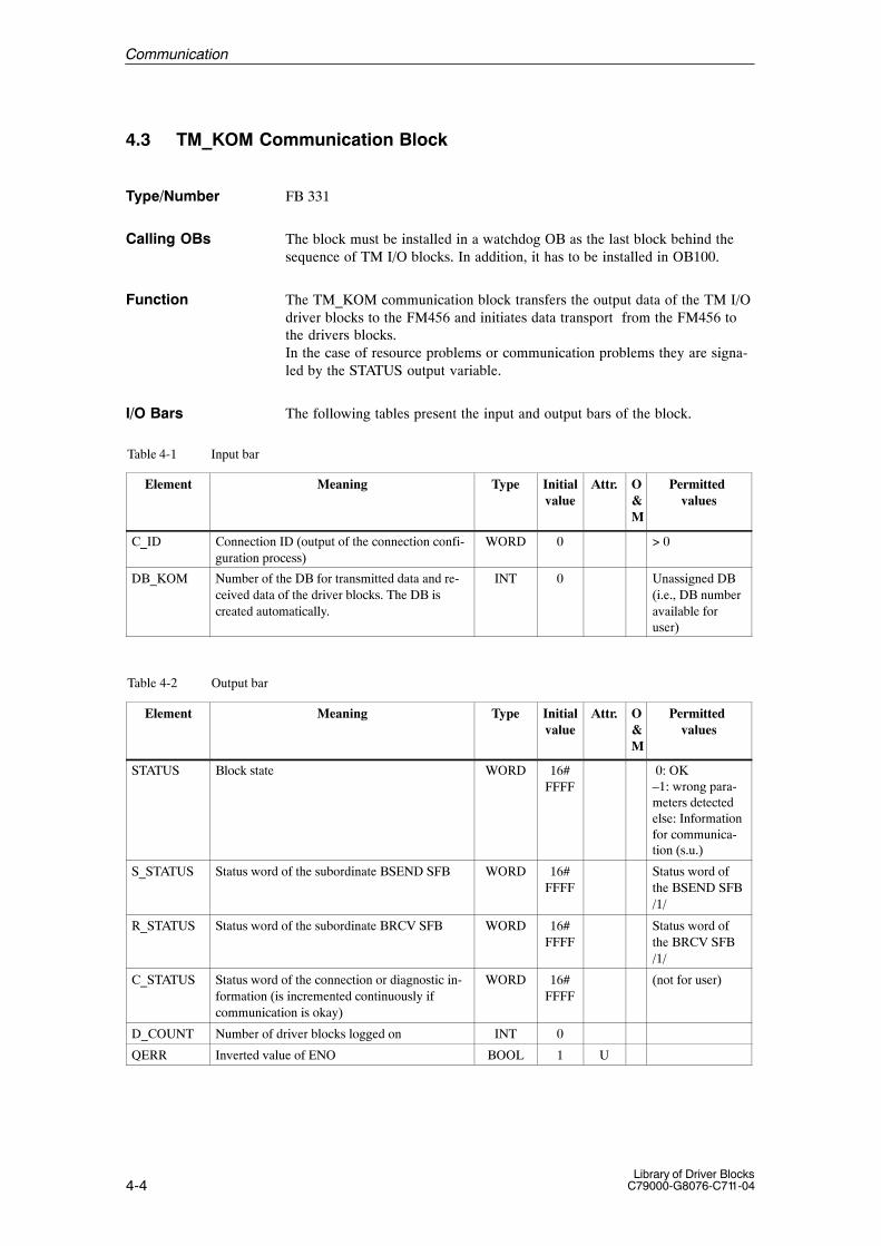
4-4Library of Driver Blocks
C79000-G8076-C711-04
4.3 TM_KOM Communication Block
FB 331
The block must be installed in a watchdog OB as the last block behind thesequence of TM I/O blocks. In addition, it has to be installed in OB100.
The TM_KOM communication block transfers the output data of the TM I/Odriver blocks to the FM456 and initiates data transport from the FM456 tothe drivers blocks.In the case of resource problems or communication problems they are signa-led by the STATUS output variable.
The following tables present the input and output bars of the block.
Table 4-1 Input bar
Element Meaning Type Initialvalue
Attr. O&M
Permitted values
C_ID Connection ID (output of the connection confi-guration process)
WORD 0 > 0
DB_KOM Number of the DB for transmitted data and re-ceived data of the driver blocks. The DB iscreated automatically.
INT 0 Unassigned DB(i.e., DB numberavailable foruser)
Table 4-2 Output bar
Element Meaning Type Initialvalue
Attr. O&M
Permitted values
STATUS Block state WORD 16#FFFF
0: OK–1: wrong para-meters detectedelse: Informationfor communica-tion (s.u.)
S_STATUS Status word of the subordinate BSEND SFB WORD 16#FFFF
Status word ofthe BSEND SFB/1/
R_STATUS Status word of the subordinate BRCV SFB WORD 16#FFFF
Status word ofthe BRCV SFB/1/
C_STATUS Status word of the connection or diagnostic in-formation (is incremented continuously if communication is okay)
WORD 16#FFFF
(not for user)
D_COUNT Number of driver blocks logged on INT 0
QERR Inverted value of ENO BOOL 1 U
Type/Number
Calling OBs
Function
I/O Bars
Communication

4-5Library of Driver BlocksC79000-G8076-C711-04
Error codes of the STATUS output value:
STATUS
(hexadecimal)Description
16#8010 Ressource problem (Error at delete DB AELI)
16#8020 Ressource problem (Error at create DB AELI)
16#8040 Initialization error
16#8080 DB 3 missing
16#8100 DB 3 too short
16#8200 Internal error No. 1
16#8400 Internal error No. 2
16#8800 Illegal number for DB_KOM (must be > 3)
16#0001 Send error (see S_STATUS)
16#0002 Receive error (see R_STATUS)
16#0003 Send error + receive error (see S_STATUS/R_STATUS)
Communication
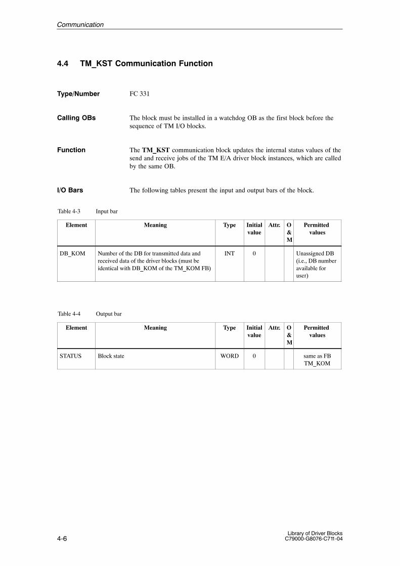
4-6Library of Driver Blocks
C79000-G8076-C711-04
4.4 TM_KST Communication Function
FC 331
The block must be installed in a watchdog OB as the first block before thesequence of TM I/O blocks.
The TM_KST communication block updates the internal status values of thesend and receive jobs of the TM E/A driver block instances, which are calledby the same OB.
The following tables present the input and output bars of the block.
Table 4-3 Input bar
Element Meaning Type Initialvalue
Attr. O&M
Permitted values
DB_KOM Number of the DB for transmitted data and received data of the driver blocks (must beidentical with DB_KOM of the TM_KOM FB)
INT 0 Unassigned DB(i.e., DB numberavailable foruser)
Table 4-4 Output bar
Element Meaning Type Initialvalue
Attr. O&M
Permitted values
STATUS Block state WORD 0 same as FBTM_KOM
Type/Number
Calling OBs
Function
I/O Bars
Communication

4-7Library of Driver BlocksC79000-G8076-C711-04
4.5 Configuration of the Connections
For each watchdog interrupt OB3x, which calls TELEPERM I/O drivers, aS7 connection between the S7 CPU and the FM456 must be configured.
Select the object Connections of the S7 CPU in the project
Define a new connection with Insert as follows:
1. Enter the SIMATIC-Station S7–CPU and the module FM456–4 as partnersof the connection.
2. Select the connection type S7 Connection
3. Set the mode ”Establish an active connection” for the S7 CPU in the ob-ject properties of the connection.
4. Note the Local Id. and its planned allocation to an alarm OB. The LocalId has been allocated automatically or modified manually.
Repeat the Steps 1 – 4 for all planned connections / watchdog alarms.
Select the configured connections between the S7–CPU and the FM456 andload the connections onto both, the S7–CPU and on the module FM456–4.
After the connections have been loaded the FM456 has to be booted.
Notice
If the procedure described above has been executed and shall be extended byconfiguring additional I/O blocks, the connections need not be modified.However the S7 CPU must be restarted, in order to allow the the driver blockto use the communication services.
Notice
After clear/reset of the S7 CPU only the system data and blocks, i.e. thewhole block container, may be loaded into the CPU, but not the connectiondata. After the CPU is restarted the connections are then active again imme-diately. After the connections have been loaded the FM456 has to be booted.
Basic rules
Configuringwith the SIMATIC Manager
Communication

4-8Library of Driver Blocks
C79000-G8076-C711-04
4.6 Other Configuration Informations
The configured instances of the communication block TM_KOM all use theglobal data block DB3. The DB3 is part of the library and is transferred to theCPU with the CFC. The DB number 3 must be kept for the instances of thecommunication block TM_KOM.
Three other blocks are subordinated under the TM_KOM and TM_KSTcommunication blocks:
� S TM_ANM,
� S TM_KIDB,
� S TM_SEND,
� S TM_RECV
These are loaded into the CPU by the CFC automatically.
When moving the allocation of the driver and communication blocks fromone watchdog alarm to another with the CFC, the blocks must be deleted inthe watchdog alarm used before (e.g. by clear/reset). Else interferences arepossible that lead to data and address errors
DB3 ist reservedfor TM_KOM.
Subordinated communication-blocksTM_ANM,TM_KIDB,TM_SEND undTM_RECV
Moving functionblocks to otherwatchdog OBs.
Communication

4-9Library of Driver BlocksC79000-G8076-C711-04
4.7 Data of the Group Interrupt Module
The system software on the FM456 checks, if a group interrupt module (mo-dule number = 61, IRQ module) is present and if an interrupt request is ac-tive. If an interrupt request is pending, the 48 Bits of the group interrupt mo-dule are transferred to the peripheral RAM area of the FM456. A status byteimmediately behind this data contains the validity information of the the in-puts of the group interrupt module.
After an interrupt has been detected and the binary values have been transfer-red to the peripheral RAM, an interrupt on the S7–CPU is triggered. The usercan then process it with an alarm OB.
Logicaladdress
Contents Remark
512 Byte 1 of the IRQ module binary values of the IRQ module
513 Byte 2 of the IRQ module binary values of the IRQ module
514 Byte 3 of the IRQ module binary values of the IRQ module
515 Byte 4 of the IRQ module binary values of the IRQ module
516 Byte 5 of the IRQ module binary values of the IRQ module
517 Byte 6 of the IRQ module binary values of the IRQ module
518 0: binary values valid1: binary values not valid
Status byte / validity code
During hardware configuration with the SIMATIC manager the logical ad-dress of the periperal area of the FM456 is set to 512 (default value). Thisvalue has to be maintained..
Logical address ofthe peripheral area= 512
Communication
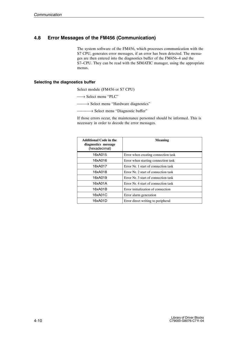
4-10Library of Driver Blocks
C79000-G8076-C711-04
4.8 Error Messages of the FM456 (Communication)
The system software of the FM456, which processes communication with theS7 CPU, generates error messages, if an error has been detected. The messa-ges are then entered into the diagnostics buffer of the FM456–4 and theS7–CPU. They can be read with the SIMATIC manager, using the appropriatemenus.
Selecting the diagnostics buffer
Select module (FM456 or S7 CPU)
⎯→ Select menu “PLC”
⎯⎯→ Select menu “Hardware diagnostics”
⎯⎯⎯→ Select menu “Diagnostic buffer”
If those errors occur, the maintenance personnel should be informed. This isnecessary in order to decode the error messages.
Additional Code in the diagnostics message
(hexadecimal)
Meaning
16xA015 Error when creating connection task
16xA016 Error when starting connection task
16xA017 Error Nr. 1 start of connection task
16xA018 Error Nr. 2 start of connection task
16xA019 Error Nr. 3 start of connection task
16xA01A Error Nr. 4 start of connection task
16xA01B Error initialization of connection
16xA01C Error alarm generation
16xA01D Error direct writing to peripheral
Communication
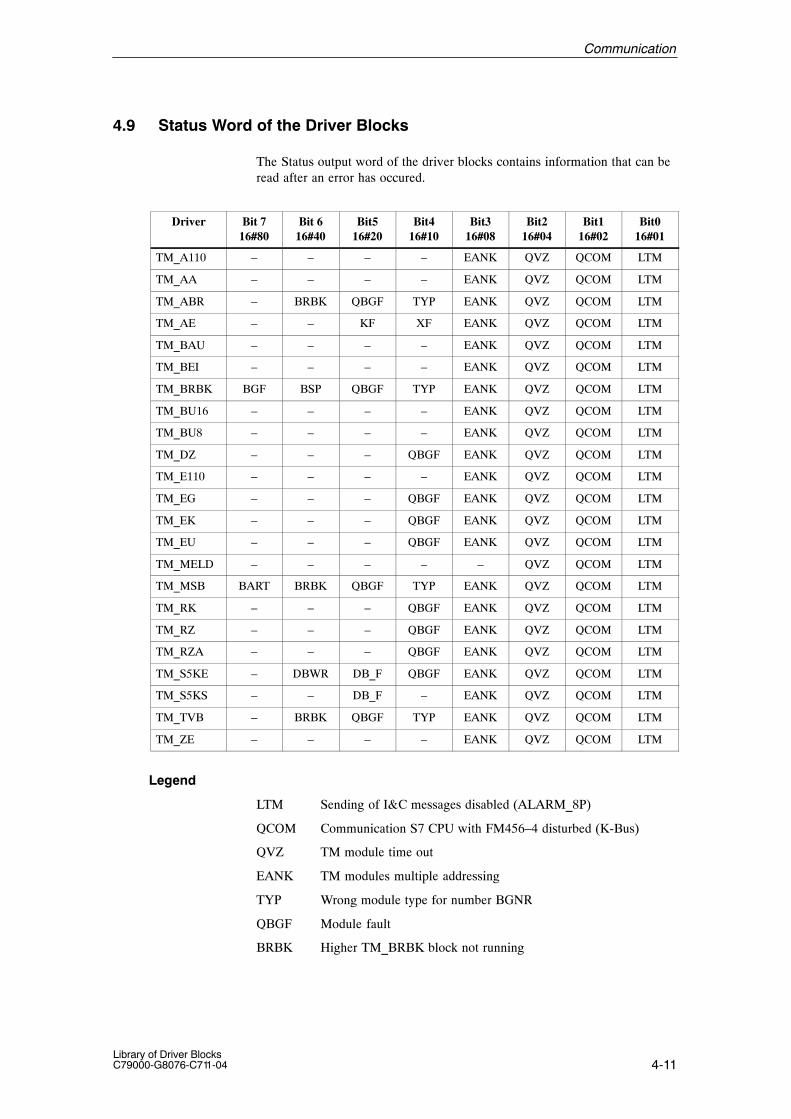
4-11Library of Driver BlocksC79000-G8076-C711-04
4.9 Status Word of the Driver Blocks
The Status output word of the driver blocks contains information that can beread after an error has occured.
Driver Bit 716#80
Bit 616#40
Bit516#20
Bit416#10
Bit316#08
Bit216#04
Bit116#02
Bit016#01
TM_A110 – – – – EANK QVZ QCOM LTM
TM_AA – – – – EANK QVZ QCOM LTM
TM_ABR – BRBK QBGF TYP EANK QVZ QCOM LTM
TM_AE – – KF XF EANK QVZ QCOM LTM
TM_BAU – – – – EANK QVZ QCOM LTM
TM_BEI – – – – EANK QVZ QCOM LTM
TM_BRBK BGF BSP QBGF TYP EANK QVZ QCOM LTM
TM_BU16 – – – – EANK QVZ QCOM LTM
TM_BU8 – – – – EANK QVZ QCOM LTM
TM_DZ – – – QBGF EANK QVZ QCOM LTM
TM_E110 – – – – EANK QVZ QCOM LTM
TM_EG – – – QBGF EANK QVZ QCOM LTM
TM_EK – – – QBGF EANK QVZ QCOM LTM
TM_EU – – – QBGF EANK QVZ QCOM LTM
TM_MELD – – – – – QVZ QCOM LTM
TM_MSB BART BRBK QBGF TYP EANK QVZ QCOM LTM
TM_RK – – – QBGF EANK QVZ QCOM LTM
TM_RZ – – – QBGF EANK QVZ QCOM LTM
TM_RZA – – – QBGF EANK QVZ QCOM LTM
TM_S5KE – DBWR DB_F QBGF EANK QVZ QCOM LTM
TM_S5KS – – DB_F – EANK QVZ QCOM LTM
TM_TVB – BRBK QBGF TYP EANK QVZ QCOM LTM
TM_ZE – – – – EANK QVZ QCOM LTM
Legend
LTM Sending of I&C messages disabled (ALARM_8P)
QCOM Communication S7 CPU with FM456–4 disturbed (K-Bus)
QVZ TM module time out
EANK TM modules multiple addressing
TYP Wrong module type for number BGNR
QBGF Module fault
BRBK Higher TM_BRBK block not running
Communication

4-12Library of Driver Blocks
C79000-G8076-C711-04
XF Analog signal disturbed
KF Channel fault
BSP Processing blocked
BGF Module fault (from module)
BART Mode BART/ESG missing
DB_F DB missing / too short
DBWR DB is write protected
Communication
A-1Library of Driver BlocksC79000-G8076-C711-04
Technical Data
This Appendix deals with the following subjects:
Section Describes Page
A.1 Hardware and software requirements A–2
A.2 Block data A–3
A.3 Data types A–5
Description ofA Appendix
A

A-2Library of Driver Blocks
C79000-G8076-C711-04
A.1 Hardware and software requirements
� SIMATIC PG or PC
� SIMATIC S7–4xx(recommended S7 416–2)
� Microsoft Windows 95
� STEP 7, minimal Version = 4.01
� SCL Compiler (for S7) and CFC recommended
� Option: WinCC V2.0 with the Option Basic Process Control(required for the usage of the OS displays (OCX))
Hardware-require-ments
Software-requirements
Technische Daten

A-3Library of Driver BlocksC79000-G8076-C711-04
A.2 Block data
In the table below the block data for block version 1.0in a CPU S7 416–2 DP, CPU version 1.0 is listed.With other CPUs the processing time depends on the CPU’s perfomance.
Meanings:
� Block type name: the symbolic identifier in the symbol table of the li-brary for the respective FB or FC. It must be unique within the project.
� Typical run time: The time which the CPU needs to process the corres-ponding block program under normal circumstances (for example, for adriver this is the execution time in the watchdog interrupt OB ).
� Block length: Memory requirements of the program code, once for everyblock type.
� Instance data length: Memory requirement of an instance DB.
� Temporary Memory: The local data memory required in a priority classwhen the block is called. This is limited CPU specifically, When it is ex-ceeded a CPU STOP is caused. You have to check it in the CPU configu-ration and, if necessary, distribute it amongst the priority classes (OBs) tomeet the real requirements.
� Multiple instance block: The specified blocks are used by the technolo-gical block and must exist in the user program (is checked by the CFC).In general these are SFB 34 (ALARM_8) and SFB 35 (ALARM_8P).They must be copied from the STDLIBS library in your user prgram.
� FB/FC No.: Block number xxx of FB xxx or FC xxx. This must be unique in your project.
Technische Daten
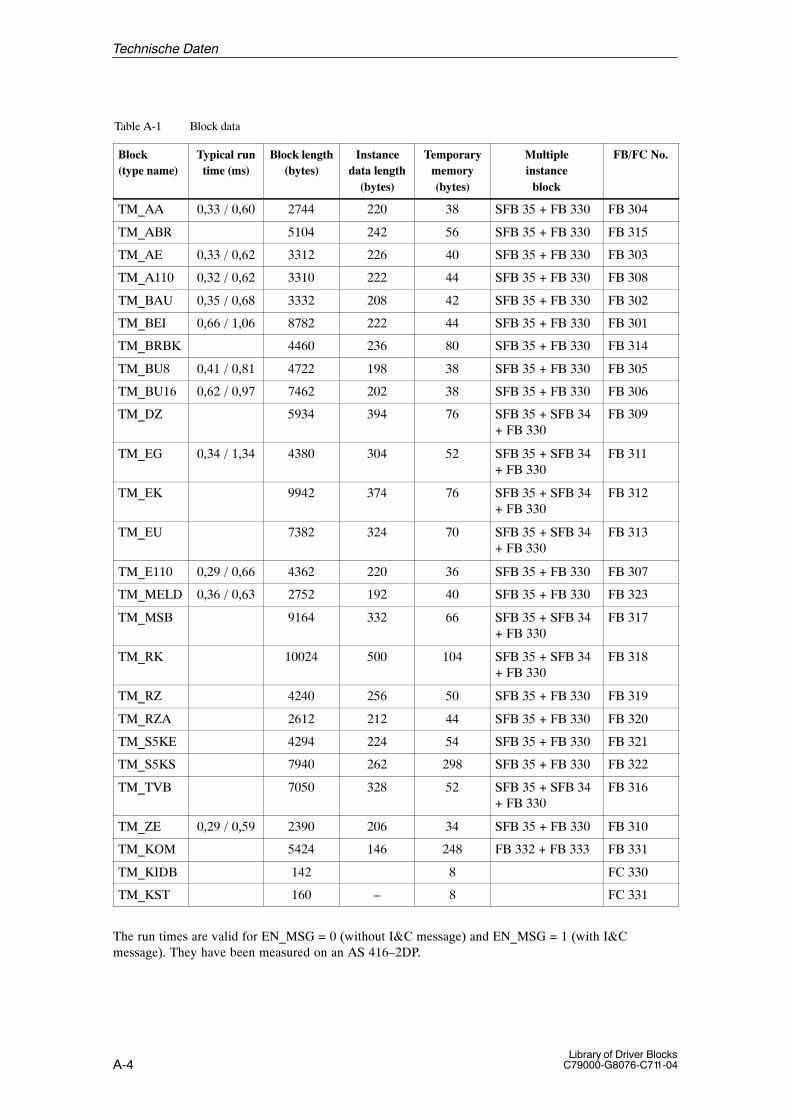
A-4Library of Driver Blocks
C79000-G8076-C711-04
Table A-1 Block data
Block(type name)
Typical runtime (ms)
Block length(bytes)
Instancedata length
(bytes)
Temporarymemory(bytes)
Multipleinstance
block
FB/FC No.
TM_AA 0,33 / 0,60 2744 220 38 SFB 35 + FB 330 FB 304
TM_ABR 5104 242 56 SFB 35 + FB 330 FB 315
TM_AE 0,33 / 0,62 3312 226 40 SFB 35 + FB 330 FB 303
TM_A110 0,32 / 0,62 3310 222 44 SFB 35 + FB 330 FB 308
TM_BAU 0,35 / 0,68 3332 208 42 SFB 35 + FB 330 FB 302
TM_BEI 0,66 / 1,06 8782 222 44 SFB 35 + FB 330 FB 301
TM_BRBK 4460 236 80 SFB 35 + FB 330 FB 314
TM_BU8 0,41 / 0,81 4722 198 38 SFB 35 + FB 330 FB 305
TM_BU16 0,62 / 0,97 7462 202 38 SFB 35 + FB 330 FB 306
TM_DZ 5934 394 76 SFB 35 + SFB 34+ FB 330
FB 309
TM_EG 0,34 / 1,34 4380 304 52 SFB 35 + SFB 34+ FB 330
FB 311
TM_EK 9942 374 76 SFB 35 + SFB 34+ FB 330
FB 312
TM_EU 7382 324 70 SFB 35 + SFB 34+ FB 330
FB 313
TM_E110 0,29 / 0,66 4362 220 36 SFB 35 + FB 330 FB 307
TM_MELD 0,36 / 0,63 2752 192 40 SFB 35 + FB 330 FB 323
TM_MSB 9164 332 66 SFB 35 + SFB 34+ FB 330
FB 317
TM_RK 10024 500 104 SFB 35 + SFB 34+ FB 330
FB 318
TM_RZ 4240 256 50 SFB 35 + FB 330 FB 319
TM_RZA 2612 212 44 SFB 35 + FB 330 FB 320
TM_S5KE 4294 224 54 SFB 35 + FB 330 FB 321
TM_S5KS 7940 262 298 SFB 35 + FB 330 FB 322
TM_TVB 7050 328 52 SFB 35 + SFB 34+ FB 330
FB 316
TM_ZE 0,29 / 0,59 2390 206 34 SFB 35 + FB 330 FB 310
TM_KOM 5424 146 248 FB 332 + FB 333 FB 331
TM_KIDB 142 8 FC 330
TM_KST 160 – 8 FC 331
The run times are valid for EN_MSG = 0 (without I&C message) and EN_MSG = 1 (with I&C message). They have been measured on an AS 416–2DP.
Technische Daten

A-5Library of Driver BlocksC79000-G8076-C711-04
Table A-2 Used multi instance blocks
Block FB/FC No. Code (bytes) Local data(bytes)
TM_ANM FB 330 1252 74
TM_BRCV FB 332 204 18
TM_BSEND FB 333 212 18
ALARM_8 SFB 34 2 –
ALARM_8P SFB 35 2 –
Technische Daten

A-6Library of Driver Blocks
C79000-G8076-C711-04
A.3 Data types
In the I/O bars of the blocks there are the following data types:
Table A-3 Data types in the I/O bars
Data type Bits Range Application example
BOOL 1 0/1 or FALSE/TRUE Switches and displays
BYTE 8 16#00 to 16#FF Driver
WORD 16 16#0000 to 16#FFFF Driver
DWORD 32 16#00000000 to 16#FFFFFFFF Batch-ID, Message number
INT 16 –32738 to 32767 Selection
DINT 32 –2147483648 to 2147483647 Counter parameter
REAL 32 –3.402822E+38 to –1.175495E–38 or 1.175495E–38 to3.402822E+38
Process values etc.
STRING[n] 8 x(n+1)
characters (text) Blocks for BATCH flexible,with dynamic associated text.
ANY 320 Interconnection information (pointer) message block, Interconnec-tion input for any qualifiers
Data types in theI/O bar
Technische Daten

B-1Library of Driver BlocksC79000-G8076-C711-04
List of Abbrevations
Application Interface
Automation system
Module fault
Module number
Module
Block receive
Block send
Continuous function chart
Communication processor
Central processing unit
Data block
Dual ported RAM (Interface between FM456–4 and TPM478–2)
Multiple addressing
Enable input
Engineering System
API
AS
BGF
BGNR
Bgr
BRCV
BSEND
CFC
CP
CPU
DB
DPRAM
EANK
EN
ES
B

B-2Library of Driver Blocks
C79000-G8076-C711-04
Function block
Function call
Function module
Instrumentation and control
International Electronical Commission
Input/output
Interrupt (request)
Communication bus
Channel number
I&C fault, control system fault message
Bus system of SIMATIC (= PROFIBUS)
Multi point interface
M7 Operating system
Organization block
O&M Operation and monitoring
Operator station (operator communication and visualization system)
Process outputs map
Process inputs map
FB
FC
FM
I&C
IEC
I/O
IRQ
K-Bus
KNR
LTM
L2
MPI
M7-SYS
OB
OS
PAA
PAE
Abkürzungsverzeichnis

B-3Library of Driver BlocksC79000-G8076-C711-04
Personal computer
Process control system
Process control system 7
Programming device
Time-out
Structured control language
System function block
System function call
Siemens network architecture
Programmable controller
Software engineering environment for SIMATIC S7 / M7
STEP 5/STEP 7 Statement list method of representation
SIMATIC line 5
SIMATIC line 7
TELEPERM M
TELEPERM process module (TPM478)
Windows control center (operator station)
PC
PCS
PCS 7
PG
QVZ
SCL
SFB
SFC
SINEC
SPS
STEP 7
STL
S5
S7
TM
TPM
WinCC
Abkürzungsverzeichnis


C-1Library of Driver BlocksC79000-G8076-C711-04
Applicable Documents
You can order the following manuals and instructions from your sales partner:
Num-ber
Title Orderfrom
Order No.
/8/ Reference ManualSIMATIC S7–400, M7–400 Programmable ControllersModule Specifications
A5E00069467-04Part of the documentationpackage with oder number6ES7498-8AA03-8BA0
/10//31/
Installation ManualSIMATIC S7–400, M7–400 Programmable ControllersHardware and Installation
A5E00069481-02Part of the documentationpackage with oder number6ES7498-8AA03-8BA0
/11/ Manuals TELEPERM M I/O-Modules– Function Modules– Signal Modules– Interface and Calculation Modules
KAKAKA
C79000-G8076-C030C79000-G8076-C031C79000-G8076-C032
/12/ ManualTELEPERM M AS 235 Automation System KA C79000-G8076-C295
/17/ ManualSIMATIC NETPROFIBUS Networks 6GK1970-5CA20-0AA1
/18/ Product BriefNetwork Solutions for PROFIBUS 6ZB5530-0AQ02-0BB0
/22/ ManualTELEPERM M CS 275 Bus System KA C79000-G8076-C006
/23/ ManualSIMATIC ET 200 Distributed I/O-System 6ES5998-3ES22
/24/ ManualSIMATIC ET 200B Distributed I/O Station 6ES5998-4ET21
/25/ ManualSIMATIC ET 200M Distributed I/O Device 6ES7153-1AA00-8BA0
/30/ ManualTELEPERM MInstructions and Guidelines for Planning, Installation and Operation KA C79000-G8076-C417
/34/ Technical DescriptionsMigration TELEPERM M – SIMATIC PCS7WinCC/TMWinCC/TM-OCX (NORA) and WinCC/TM-OCX (PCS7)
KAKA
C79000-T8076-C740C79000-T8076-C741
/100/ ManualCoupling of TELEPERM I/O Peripherie with PCS 7
KA C79000-G8076-C710(in preparation)
C

C
C-2Library of Driver Blocks
C79000-G8076-C711-04
Num-ber
Order No.Orderfrom
Title
/106/ ReferenzhandbuchSIMATIC PCS 7 Driver Blocks
A5E00057447-02
/107/ ManualSIMATIC PCS 7 Technological Blocks
C79000-G7076-C715
Applicable Documents

Glossary-1Library of Driver BlocksC79000-G8076-C711-04
Glossary
A
Aspect Attributes of a block with regard to its application in the AS (FB, FC), ES(display in the library or in CFC, display for testing and commissioningpurposes) and OS (texts for messages and operations, correspondingfaceplate for visualization in the OS).
B
Block Object of a library or of a block structure, divided into function blocks(executable on an automation system) and faceplates (display blocks)(executable on an OS). The block has aspects for AS, OS and ESwhich are described by properties. Both blocks are configured with ES.The block type is contained in the library. ES is used to create an in-stance data block and to configure it further.
Block library Software package which contains block types combined in accordancewith common features. It is installed via ES.
Block header Section of the block with management information on its assignment(for example type name, block name, etc.).
Block body Section of the block with function-specific information (for example va-lues at data blocks, program code at functions).
Block type Object of a library which passes its properties to the respective in-stance data block when it is used in a block structure. The block type(method, data maintenance and aspect description) is stored in ES.
Glossary-2Library of Driver Blocks
C79000-G8076-C711-04
C
CS Bus system for exchanging data between components.
Combined block Block which is formed from basic blocks and/or combined blocks (seemulti-instance blocks)
D
Data block This is used for storing data which are processed by programs or func-tions.
Display element Object as a component of the faceplate which corresponds to a specificI/O element of a block type.
Driver block Block which imports and exports automation-system values into or fromthe module. It forms the software interface to the process, converts thephysical values into process values (and vice versa) and supplies addi-tional information with regard to the availability of the hardware addres-sed.
E
Enable input Enable input, through which processing of a function block is enabledor disabled (only exists in CFC display mode).
F
Block which is executable in the OS and which is used to operate andmonitor the corresponding automation-system block. It is also suppliedfor certain block types in the libraries. Also includes checking of theoperated values.
Faceplate (display block
Glossary
Glossary-3Library of Driver BlocksC79000-G8076-C711-04
Fetch principle The value which is interconnected to an input of a block is only updated(fetched) by the method associated with the block of the interconnectedinput and not earlier. If this block is not processed, the input will nothave an updated value, despite its being interconnected.
Function This term is defined in IEC 1131–3 as a software unit which when ex-ecuted delivers a single result (which can also be a complex data type)and which does not have the capability of saving data (memory).The essential difference between it and an FB is the lack of a data sto-rage capability (instance). The result of the FC call must therefore ei-ther be saved explicitly by the user or it must be used immediately. TheFC is represented similarly to the FB (with several inputs and one out-put) for the process control system user programming with the ES ensuring that handling is uniform.
Function block In accordance with the IEC TC65/WG6 draft standard of May 1995 thisterm is defined as follows:The function block (FB instance) is a functional software unit whichconsists of a designated individual copy of the data structure defined bythe function block type, with the data structure being retained from onecall of the function block to the next.
The main features of the FB instance are as follows:
· Type and instance identifier· Input and output events. These use algorithms of the OB in which the
FB instance is processed or are used by these algorithms.· Input or output variables which are read or changed respectively by
the FB algorithm.· Functional features which are defined by the type description and
which are generally realized via the algorithm of the FB.
As a rule the algorithm of an FB is not visible from outside the FB unless the FB manufacturer describes it in any form.
Result: The user sees the FB through the data storage as an input/out-put bar with the information: ”What must exist at which input in order forthe desired result to be obtained at the defined output?”. The FB manu-facturer has dealt with the question of how the result is obtained. Theuser can thus restrict himself to the technological aspects without ha-ving to deal with the programming details. Suitable means (ES) can beused to ensure that the FBs are handled graphically, in a clear structureand with additional ease.
Glossary

Glossary-4Library of Driver Blocks
C79000-G8076-C711-04
I
Initial startup From the point of view of the block the process in which the block isexecuted for the first time after having been instanced. Afterwards theblock is in a defined state with regard to its parameters and operatingmodes.
Installation Process by means of which a block (FB or FC) in an OB is logged in forprocessing. As a rule an existing processing sequence must be obser-ved, which is why the term ”install” is used instead of ”insert” here.
Instance DB Data block which results from a block type and which serves as thestorage unit for a concrete application of this type. In a project, for ex-ample, the ”control” block type is represented by several instances (in-stance DBs) in order to be able to save the respective setpoint value,operating mode, parameters, etc. for each control task.
L
Limit Reference value for an analog variable which leads to a reaction whenthe value is reached or exceeded.
Glossary

Glossary-5Library of Driver BlocksC79000-G8076-C711-04
M
Message class Classification of messages in accordance with their cause. The follo-wing message classes are used in the SIMATIC process control sy-stem:
Process signals which are triggered when process-specific monitoringvalues (for example: alarms, interrupts, upper/lower tolerance, generalprocess signals) are reached or exceeded.
Control system messages which are output by the control system (sy-stem messages), the I/O units (errors in the field) or for preventivemaintenance.
Requests for operator input which, in the case of certain operation se-quences, draw the operator’s attention to the necessity of an operatorintervention (for example, request to acknowledge a stepping operationmanually in order to enable transition) or operator input lists.
Table of possible message classes and their meaning:
Message class MeaningAH Alarm high (high high alarm)WH Warning high (high alarm)WL Warning low (low alarm)AL Alarm low (low low alarm)TH Tolerance highTL Tolerance lowF Process error (field)S Control system message (system)S* OS control system message (fault)M Preventive maintenancePM Process message– Operation messageOR Operator requestOM* 1) Operation message
1) If the block is used for operation messages, the inputs I_1, ... have to be supplied with pulses. Assignment of the static value 1 would lead to multiple messages.
Monitoring Part of the tasks of an OS which allows visualization of the processparameters and states in various forms (numerical, graphical).
Glossary
Glossary-6Library of Driver Blocks
C79000-G8076-C711-04
We speak of multiple instances in cases where additional functionblocks are called by one block using its own (meaning without an addi-tional) instance DB.
Prerequisite is that the FBs to be called are registered as static varia-bles in the variable declaration of the FB to be called.
This ensures that a concentration of the instance data in one instancedata block is reached, meaning that the number of DBs available canbe used better.
O
Operator control Process in which the plant operator induces changes in values or sta-tes at a block. As a rule these are initiated by entries at the OS, chek-ked and transferred via the CS to the operator control block in the auto-mation system. Because the working process may have changed in thetime between the OS sending and the automation system receiving afinal check is carried out here before it is assigned to the block.
Block which checks the plant operator intervention at the OS end and,if it is permissible, makes it available in the automation system at theblock input interconnected to it. At the same time it presents confirma-tion of the operation at the OS end.
Operator control text Text which is allocated to a block input and which is used for image dis-play or for logging the operations on the OS.
Operating mode Characteristic of a block which marks a certain application-specific pro-cessing phase for various cases in the course of the block program.Thus, for example the MANUAL operating mode at a control block si-gnifies the program sequence in which the controller algorithm is notexecuted and the output variable (manipulated variable) is stipulatedmanually by the operator. The operating mode is usually coded in theblock. It is selected or displayed by means of an integer parameter orcombinations of binary parameters.
R
Redundancy Multiple existence of components having the same tasks, which if re-quired (for example in case of errors or faults) can take over from eachother.
Multiple instanceblock
Operator controlblock
Glossary

Glossary-7Library of Driver BlocksC79000-G8076-C711-04
S
Sampling time Interval between two consecutive scans of a block in a temporally equi-distant processing class (watchdog interrupt OB). It is defined by theES on the basis of the configured runtime group.
Generic term for all objects in standard libraries which are supplied bySiemens.
Startup From the point of view of the CPU the transition between the operatingstatus STOP (internal STOP, i.e. CPU is ready) and operating statusRUN (with processing of the user programs). The following types ofstartups can be differentiated on the basis of the organization blocks(CPU specific):
Cold restart, in which the results and states at interrupts are not takeninto consideration (OB100).
Restart, in which the results and states of the user program at the inter-rupt are considered (not relevant for this library).
Transition of a block into a defined state after it has been processed ina start-up OB. In this library only a cold restart is relevant (OB100).
T
Tracking Status, which can be activated, of a block during which a (tracked) pa-rameter is overwritten by its own program with the value of another pa-rameter (tracking value). This means that a value defined by the usercan be forced upon a parameter which is usually determined by a pro-cess or program.
U
Generic term for all the objects supplied by the user (customer, engi-neering office, department planning a project for a customer) in user-specific libraries.
Standard (block,display block
Start-upcharacteristics
User (block, display block)
Glossary
