process control system pcs 7 v7.0 - programming ... · process control system pcs 7 v7.0 -...
TRANSCRIPT
s
Preface, Contents Creating AS Blocks 1 Creating Faceplates 2 Creating Online Help 3 Creating a Library and Setup 4 Appendix Samples: Source code of blocks MEAS_MON, MOTOR and VALVE
A Index
SIMATIC
Process Control System PCS 7 V7.0 Programming Instructions for Blocks Manual
11/2006 A5E00807905-01
Siemens AG Automation and Drives Postfach 4848 90437 NÜRNBERG GERMANY
A5E00807905-01 11/2006
Copyright © Siemens AG 2006 Technical data subject to change
Safety Guidelines This manual contains notices you have to observe in order to ensure your personal safety, as well as to prevent damage to property. The notices referring to your personal safety are highlighted in the manual by a safety alert symbol, notices referring to property damage only have no safety alert symbol. The notices shown below are graded according to the degree of danger.
! Danger indicates that death or severe personal injury will result if proper precautions are not taken.
! Warning indicates that death or severe personal injury may result if proper precautions are not taken.
! Caution with a safety alert symbol indicates that minor personal injury can result if proper precautions are not taken.
Caution
without a safety alert symbol indicates that property damage can result if proper precautions are not taken.
Notice
indicates that an unintended result or situation can occur if the corresponding notice is not taken into account.
If more than one degree of danger is present, the warning notice representing the highest degree of danger will be used. A notice warning of injury to persons with a safety alert symbol may also include a warning relating to property damage.
Qualified Personnel The device/system may only be set up and used in conjunction with this documentation. Commissioning and operation of a device/system may only be performed by qualified personnel. Within the context of the safety notices in this documentation qualified persons are defined as persons who are authorized to commission, ground and label devices, systems and circuits in accordance with established safety practices and standards.
Prescribed Usage Note the following:
! Warning This device and its components may only be used for the applications described in the catalog or the technical description, and only in connection with devices or components from other manufacturers which have been approved or recommended by Siemens. Correct, reliable operation of the product requires proper transport, storage, positioning and assembly as well as careful operation and maintenance.
Trademarks All names identified by ® are registered trademarks of the Siemens AG. The remaining trademarks in this publication may be trademarks whose use by third parties for their own purposes could violate the rights of the owner.
Disclaimer of Liability We have reviewed the contents of this publication to ensure consistency with the hardware and software described. Since variance cannot be precluded entirely, we cannot guarantee full consistency. However, the information in this publication is reviewed regularly and any necessary corrections are included in subsequent editions.

Process Control System PCS 7 V7.0 - Programming Instructions for Blocks A5E00807905-01 iii
Preface
Purpose of the Programming Instructions These Programming Instructions describe how to create PCS 7-compliant PLC blocks or faceplates.
The essential differences between a PCS 7-compliant PLC block and a straightforward S7 block are as follows:
• The option of monitoring parameter values in a faceplate
• The option of controlling parameter values and therefore the way the block executes in a faceplate
• The option of sending messages relating to asynchronous events and block states to the OS and to display these messages in a faceplate or a WinCC message list.
Audience These programming instructions are intended for developers of automation blocks (PLC blocks) and/or faceplates that will be used and fully integrated in the same systems as the PCS 7 process control blocks supplied by Siemens.
Requirements To use these programming instructions, you therefore require experience in the development and application of PLC blocks and faceplates and should be familiar with the relevant hardware and software. These instructions describe only the measures necessary to achieve conformity between blocks you have created yourself and the PCS 7 blocks. Where necessary, you will find further information in the documentation listed in the References at the end of this manual.
You will find general information on the use of PCS 7 components in the PCS 7 Configuration Manual.
Preface
Process Control System PCS 7 V7.0 - Programming Instructions for Blocks iv A5E00807905-01
General Outline These programming instructions provide you with an overview of the individual components of a PCS 7-compliant block. The order in which they are introduced is the same order you would follow to develop function blocks and faceplates.
• You develop the "CONTROL" PLC block, a simple controller block, step by step by first defining the block header, the parameters of the block and its local variables. You then create the source code.
• The next step is to develop a faceplate. You create this with the WinCC Graphics Designer and the elements of the Faceplate Designer.
• The last step is to develop an online help system for the block and then a shippable library MYLIB made up of all the components.
As you work through the instructions, you will see the sections of the sample block required to understand the current topic. Section 1.11 contains a printout of the entire sample PLC block.
In the appendix, you will find a sample source code for MEAS_MON, MOTOR and VALVE blocks contained in the PCS 7 library, as an example of PCS 7-compliant blocks. You can use this source code - or part thereof - as a template for your own blocks.
Note
The use of the sample source code contained in the appendix is the responsibility of the user. There is no guarantee for error-free display.
Further Support If you have any technical questions, please get in touch with your Siemens representative or agent responsible.
You will find your contact person at:
http://www.siemens.com/automation/partner
You will find a guide to the technical documentation offered for the individual SIMATIC Products and Systems here at:
http://www.siemens.com/simatic-tech-doku-portal
The online catalog and order system is found under:
http://mall.ad.siemens.com/
Training Centers Siemens offers a number of training courses to familiarize you with the Process Control System PCS 7 automation system. Please contact your regional training center or our central training center in D 90327 Nuremberg, Germany for details: Telephone: +49 (911) 895-3200. Internet: http://www.sitrain.com
Preface
Process Control System PCS 7 V7.0 - Programming Instructions for Blocks A5E00807905-01 v
Technical Support You can reach the Technical Support for all A&D products
• Via the Web formula for the Support Request http://www.siemens.com/automation/support-request
• Phone: + 49 180 5050 222
• Fax: + 49 180 5050 223
Additional information about our Technical Support can be found on the Internet pages http://www.siemens.com/automation/service
Service & Support on the Internet In addition to our documentation, we offer our Know-how online on the internet at: http://www.siemens.com/automation/service&support
where you will find the following:
• The newsletter, which constantly provides you with up-to-date information on your products.
• The right documents via our Search function in Service & Support.
• A forum, where users and experts from all over the world exchange their experiences.
• Your local representative for Automation & Drives.
• Information on field service, repairs, spare parts and more under "Services".

Preface
Process Control System PCS 7 V7.0 - Programming Instructions for Blocks vi A5E00807905-01
Process Control System PCS 7 V7.0 - Programming Instructions for Blocks A5E00807905-01 vii
Contents
1 Creating AS blocks 1-1 1.1 Requirements and previous experience........................................................... 1-1 1.1.1 Introduction ....................................................................................................... 1-1 1.1.2 How to integrate the included block template into your project ........................ 1-2 1.2 Structure of an AS block................................................................................... 1-3 1.2.1 SCL Compiler settings ...................................................................................... 1-4 1.2.2 SIMATIC Manager settings .............................................................................. 1-6 1.2.3 Block header..................................................................................................... 1-8 1.2.4 Declaration section ......................................................................................... 1-14 1.2.4.1 Block parameters............................................................................................ 1-14 1.2.4.2 Local variables................................................................................................ 1-22 1.2.5 Code section................................................................................................... 1-24 1.3 Initialization ..................................................................................................... 1-25 1.4 Time dependency ........................................................................................... 1-26 1.5 Handling asynchronous startup and error OBs .............................................. 1-28 1.6 Operating, monitoring and reporting............................................................... 1-30 1.6.1 Message suppression at startup..................................................................... 1-35 1.6.2 Suppressing specific messages ..................................................................... 1-37 1.6.3 Compiling the source code ............................................................................. 1-38 1.7 Configuring messages.................................................................................... 1-39 1.8 Integration of SIMATIC BATCH...................................................................... 1-43 1.9 Creating CFC block types............................................................................... 1-44 1.9.1 CFC................................................................................................................. 1-44 1.9.2 Example: CONTROL2 .................................................................................... 1-44 1.10 Naming conventions and range of numbers................................................... 1-46 1.11 Source code of the example........................................................................... 1-47
2 Configuring faceplates 2-1 2.1 General notes re configuration ......................................................................... 2-1 2.1.1 Requirements and previous experience........................................................... 2-1 2.1.2 Creation phases................................................................................................ 2-2 2.1.2.1 Roadmap to creation ........................................................................................ 2-2 2.1.2.2 Design of the faceplate..................................................................................... 2-2 2.1.2.3 Configuring the faceplate.................................................................................. 2-3 2.1.2.4 How to test a faceplate ..................................................................................... 2-4 2.1.3 Creating faceplates using Faceplate Designer................................................. 2-5 2.1.3.1 Faceplate Designer........................................................................................... 2-5 2.1.3.2 Templates of Faceplate Designer..................................................................... 2-5 2.1.3.3 Block icon templates......................................................................................... 2-5 2.1.3.4 Picture templates .............................................................................................. 2-6 2.1.3.5 Configuring sequence....................................................................................... 2-7 2.1.4 Access control .................................................................................................. 2-8 2.1.4.1 Assigning user rights ........................................................................................ 2-8 2.1.4.2 Configuring user rights for basic elements ....................................................... 2-9 2.1.5 Changing the overview ................................................................................... 2-10 2.1.6 Configuring multiple instances........................................................................ 2-11

Contents
Process Control System PCS 7 V7.0 - Programming Instructions for Blocks viii A5E00807905-01
2.1.7 Configuring number formats ........................................................................... 2-15 2.1.8 Configuring the trend view.............................................................................. 2-16 2.1.9 How to configure an AS block type with different block icons
and faceplate types......................................................................................... 2-21 2.1.10 WebClient (differences compared to WinCC)................................................. 2-22 2.1.10.1 Differences in terms of faceplate configuration .............................................. 2-22 2.1.10.2 Picture names................................................................................................. 2-22 2.1.10.3 Case-sensitivity in file names ......................................................................... 2-23 2.1.10.4 Loading pictures in picture windows............................................................... 2-23 2.1.10.5 Deselecting pictures within scripts.................................................................. 2-24 2.1.10.6 Distinguishing between the WinCC <-> Web runtime environments ............. 2-24 2.1.10.7 Function names in WinCC/Web ..................................................................... 2-25 2.1.10.8 Global script.................................................................................................... 2-26 2.1.10.9 VBS Script ...................................................................................................... 2-26 2.1.10.10 Notes............................................................................................................... 2-26 2.1.11 Changing languages....................................................................................... 2-27 2.1.12 Texts for the input of analog and binary values from the ES.......................... 2-27 2.2 Working with Faceplate Designer................................................................... 2-36 2.2.1 Example: Creating a new controller faceplate................................................ 2-38 2.2.1.1 How to create templates................................................................................. 2-38 2.2.1.2 Editing templates ............................................................................................ 2-41 2.2.1.3 How to edit the picture template @PG_REG_NEU_STANDARD.pdl............ 2-42 2.2.1.4 How to edit the picture @PG_REG_NEU_NEUESICHT1.pdl........................ 2-43 2.2.1.5 Dynamic update of faceplates ........................................................................ 2-43 2.2.1.6 Creating a loop view ....................................................................................... 2-44 2.2.1.7 Generating an additional view ........................................................................ 2-44 2.3 Basic elements ............................................................................................... 2-45 2.3.1 Storage location of the basic elements........................................................... 2-45 2.3.2 Display and control of analog values.............................................................. 2-45 2.3.3 Visualization of analog values using the "AdvancedAnalogDisplay".............. 2-49 2.3.4 Static text ........................................................................................................ 2-49 2.3.5 Standard bar graph for analog values ............................................................ 2-50 2.3.6 Double bar graph for analog values ............................................................... 2-51 2.3.7 Horizontal bar graph ....................................................................................... 2-53 2.3.8 "Limit value display" bar graph ....................................................................... 2-54 2.3.9 "Message suppression" display...................................................................... 2-56 2.3.10 "Batch Occupied" display................................................................................ 2-57 2.3.11 Acknowledgment of messages from the selected block................................. 2-57 2.3.12 "Locked" display block (valve, motor)............................................................. 2-58 2.3.13 Group display.................................................................................................. 2-58 2.3.14 Binary value input using "Check Box_R"........................................................ 2-59 2.3.15 Binary value control using "Check Box_L" ..................................................... 2-61 2.3.16 Binary value control using a combo box......................................................... 2-62 2.3.17 Binary value control using a combo box (3ComboBox) ................................. 2-64 2.3.18 Binary value control with button and color change......................................... 2-66 2.3.19 Binary value input using buttons..................................................................... 2-67 2.3.20 Status display with two alternatives................................................................ 2-68 2.3.21 Status display with n alternatives ................................................................... 2-69 2.3.22 "Valve" status display ..................................................................................... 2-70 2.3.23 "Motor" status display ..................................................................................... 2-71 2.3.24 Configuring permissions ................................................................................. 2-71 2.3.25 "OpenNextFaceplate" button .......................................................................... 2-74 2.3.26 "Disable / Enable messages" button .............................................................. 2-76 2.3.27 Quality Code displays ..................................................................................... 2-77
Contents
Process Control System PCS 7 V7.0 - Programming Instructions for Blocks A5E00807905-01 ix
2.4 Scripts ............................................................................................................. 2-78 2.5 Bitmaps........................................................................................................... 2-80 2.6 Pictures........................................................................................................... 2-82 2.7 Faceplates ...................................................................................................... 2-83 2.7.1 Basic data of the picture templates ................................................................ 2-83 2.7.1.1 @PG_%Type%.pdl......................................................................................... 2-83 2.7.1.2 @PG_%TYPE% ............................................................................................. 2-85 2.7.1.3 @PG_%Type%_%View%.pdl ........................................................................ 2-86 2.7.2 Global views ................................................................................................... 2-87 2.7.2.1 Message view ................................................................................................. 2-87 2.7.2.2 Batch view ...................................................................................................... 2-87 2.7.2.3 Trend view ...................................................................................................... 2-88 2.7.3 CTRL_PID ...................................................................................................... 2-89 2.7.3.1 CTRL_PID: Views........................................................................................... 2-89 2.7.3.2 CTRL_PID: Standard view.............................................................................. 2-89 2.7.3.3 CTRL_PID: Maintenance view ....................................................................... 2-91 2.7.3.4 CTRL_PID: Parameter view ........................................................................... 2-93 2.7.3.5 CTRL_PID: Limits view................................................................................... 2-95 2.8 Block icons...................................................................................................... 2-97 2.8.1 Process control ............................................................................................... 2-97 2.8.2 @@PCS7Typicals.pdl and @Template.pdl picture templates....................... 2-97 2.8.3 Block icons in the @@PCS7_Typicals picture............................................... 2-99 2.8.4 Properties of the block icons ........................................................................ 2-100 2.8.4.1 General properties ........................................................................................ 2-100 2.8.4.2 CTRL_PID .................................................................................................... 2-101 2.8.4.3 CTRL_S ........................................................................................................ 2-102 2.8.4.4 DOSE............................................................................................................ 2-104 2.8.4.5 FMCS_PID/FMT_PID ................................................................................... 2-105 2.8.4.6 ELAP_CNT ................................................................................................... 2-106 2.8.4.7 MEAS_MON ................................................................................................. 2-106 2.8.4.8 SWIT_CNT ................................................................................................... 2-107 2.8.4.9 RATIO_P ...................................................................................................... 2-107 2.8.4.10 OP_A ............................................................................................................ 2-108 2.8.4.11 OP_A_LIM .................................................................................................... 2-108 2.8.4.12 OP__A_RJC ................................................................................................. 2-108 2.8.4.13 VALVE .......................................................................................................... 2-109 2.8.4.14 VAL_MOT ..................................................................................................... 2-109 2.8.4.15 MOTOR......................................................................................................... 2-110 2.8.4.16 MOT_SPED .................................................................................................. 2-111 2.8.4.17 MOT_REV .................................................................................................... 2-112 2.8.4.18 INTERLOK.................................................................................................... 2-112 2.8.4.19 OP_D3 .......................................................................................................... 2-113 2.8.4.20 OP_D ............................................................................................................ 2-113 2.8.4.21 OP_TRIG ...................................................................................................... 2-113 2.8.4.22 DIG_MON ..................................................................................................... 2-114

Contents
Process Control System PCS 7 V7.0 - Programming Instructions for Blocks x A5E00807905-01
3 Creating the Online Help 3-1 3.1 Requirements ................................................................................................... 3-1 3.2 Structure of the help file.................................................................................... 3-1 3.3 Structure of the registry file............................................................................... 3-3 3.4 Special features for creating help files for SFC templates ............................... 3-5
4 Creating a library and setup 4-1 4.1 Requirements ................................................................................................... 4-1 4.2 Creating a library .............................................................................................. 4-1 4.3 Create a Setup routine...................................................................................... 4-2
A Samples: Source code of blocks MEAS_MON, MOTOR and VALVE A-1 A.1 MEAS_MON .....................................................................................................A-1 A.2 MOTOR.............................................................................................................A-7 A.3 Valve...............................................................................................................A-15
Glossary Glossary-1
Index Index-1
Process Control System PCS 7 V7.0 - Programming Instructions for Blocks A5E00807905-01 1-1
1 Creating AS blocks
1.1 Requirements and previous experience
1.1.1 Introduction
Requirements Prerequisite for the creation of AS blocks:
• PCS 7 V6.1 or higher installation on S7-4xx CPU
• Software packages required to create the blocks:
- STEP 7 Basis V5.2 or higher
- SCL Compiler V5.1 SP4 or higher
- CFC V6.0 or higher
Additional information re SCL AS blocks for PCS 7 are programmed using SCL.
For further information on SCL, refer to:
• The SIMATIC Manager Online Help: Select Call help on optional packages > Programming blocks with S7 SCL
• S7 SCL Getting Started manual
• S7-SCL for S7-300 and S7-400 manual
These manuals are available at Start > Simatic > Documentation.
Information on user DBs These instructions do not cover the creation of data blocks (DBs). When creating your own DBs in addition to function blocks (FBs):
• Use a DB number within the range from 1 to 60 which is reserved in CFC for other applications This rules out any conflict between the instance DBs generated by the CFC compiler and the user DB numbers
• Any change of the default range of numbers in the CFC forces you to download all configuration data while the CPU is in stop You can edit the default range of numbers in CFC by selecting the Tools > Settings for compiling / downloading command
Creating AS blocks
Process Control System PCS 7 V7.0 - Programming Instructions for Blocks 1-2 A5E00807905-01
1.1.2 How to integrate the included block template into your project
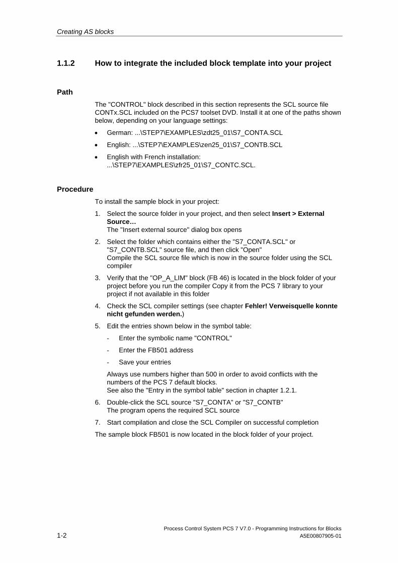
Path The "CONTROL" block described in this section represents the SCL source file CONTx.SCL included on the PCS7 toolset DVD. Install it at one of the paths shown below, depending on your language settings:
• German: ...\STEP7\EXAMPLES\zdt25_01\S7_CONTA.SCL
• English: ...\STEP7\EXAMPLES\zen25_01\S7_CONTB.SCL
• English with French installation: ...\STEP7\EXAMPLES\zfr25_01\S7_CONTC.SCL.
Procedure To install the sample block in your project:
1. Select the source folder in your project, and then select Insert > External Source… The "Insert external source" dialog box opens
2. Select the folder which contains either the "S7_CONTA.SCL" or "S7_CONTB.SCL" source file, and then click "Open" Compile the SCL source file which is now in the source folder using the SCL compiler
3. Verify that the "OP_A_LIM" block (FB 46) is located in the block folder of your project before you run the compiler Copy it from the PCS 7 library to your project if not available in this folder
4. Check the SCL compiler settings (see chapter Fehler! Verweisquelle konnte nicht gefunden werden.)
5. Edit the entries shown below in the symbol table:
- Enter the symbolic name "CONTROL"
- Enter the FB501 address
- Save your entries
Always use numbers higher than 500 in order to avoid conflicts with the numbers of the PCS 7 default blocks. See also the "Entry in the symbol table" section in chapter 1.2.1.
6. Double-click the SCL source "S7_CONTA" or "S7_CONTB" The program opens the required SCL source
7. Start compilation and close the SCL Compiler on successful completion
The sample block FB501 is now located in the block folder of your project.
Creating AS blocks
Process Control System PCS 7 V7.0 - Programming Instructions for Blocks A5E00807905-01 1-3
1.2 Structure of an AS block
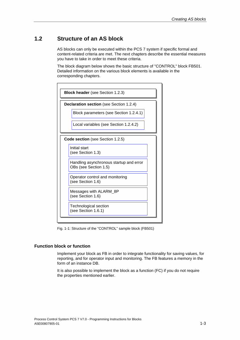
AS blocks can only be executed within the PCS 7 system if specific formal and content-related criteria are met. The next chapters describe the essential measures you have to take in order to meet these criteria.
The block diagram below shows the basic structure of "CONTROL" block FB501. Detailed information on the various block elements is available in the corresponding chapters.
Declaration section (see Section 1.2.4)
Block header (see Section 1.2.3)
Block parameters (see Section 1.2.4.1)
Local variables (see Section 1.2.4.2)
Code section (see Section 1.2.5)
Handling asynchronous startup and errorOBs (see Section 1.5)
Operator control and monitoring(see Section 1.6)
Messages with ALARM_8P(see Section 1.6)
Technological section(see Section 1.6.1)
Initial start(see Section 1.3)
Fig. 1-1: Structure of the "CONTROL" sample block (FB501)
Function block or function Implement your block as FB in order to integrate functionality for saving values, for reporting, and for operator input and monitoring. The FB features a memory in the form of an instance DB.
It is also possible to implement the block as a function (FC) if you do not require the properties mentioned earlier.
Creating AS blocks
Process Control System PCS 7 V7.0 - Programming Instructions for Blocks 1-4 A5E00807905-01
1.2.1 SCL Compiler settings
Default settings for "Generate blocks" The SCL Compiler supports the configuration of specific options. Open the corresponding dialog by selecting Options > Settings > Generate blocks.
• Overwrite blocks
- Overwrites blocks in the "Blocks" folder of an S7 program if the compiler has generated blocks with the same name
- Overwrites blocks of the same name in the target system during downloads
If this option is not enabled a message prompts you to confirm overwriting of the block.
• Display warnings
Defines whether to output warning messages in addition to error messages after compilation.
• Display errors before warnings
Defines whether errors are listed before warnings in the message.
• Generate reference data
Automatically generates a block plus reference data
Select Options > Reference data in order to generate or update the reference data at a later time.
• Include system attribute "S7_server"
You set this option to include the system attribute of parameter "S7_server" when the compiler generates a block. Assign this attribute to the parameter if relevant to the configuration of connections or messages. The parameter contains the connection numbers and/or message numbers.
Note
(for this example) Always set the "Include system attribute "S7_server" check box because this block contains messages. If the check box is not set the program returns an error message and cancels any operation which imports a block and/or inserts a block into a CFC chart.
Creating AS blocks
Process Control System PCS 7 V7.0 - Programming Instructions for Blocks A5E00807905-01 1-5
"Compiler" settings You can activate/deactivate the check boxes listed below in the SCL Compiler by selecting Options > Customize > Compiler.
• "Monitor field limits"
• "Generate debug info"
• "Set OK flag"
It is advisable to activate all remaining check boxes. For further information on the various options, refer to the SCL manual.
Make allowances for conditions outlined below when you activate/deactivate any of these options:
• Monitor field limits
At runtime, the program validates the range of the array index and field length declaration of any arrays used. The program toggles the OK bit and resets the ENO output when an error is detected. This validation imposes a considerable load on the runtime system.
Activate this option only as long as necessary when validating arrays, i.e. reset it after you successfully completed the block test and verified that the index matches the field length.
• Generate debug info
This option enables you to debug the compiled program after its download to the CPU. However, this option increases memory requirements of the program and load on AS runtime. You should therefore activate this option only for block testing and deactivate it in its delivered version.
• Set OK flag
The OK flag is an internal system variable. When the system detects an error such as overflow in mathematical operations during execution of an operation, it toggles the OK bit and transfers this bit information to the ENO output. This validation generates considerable load on system performance. You should for this reason disable automatic setting of the OK flag and capture any illegal operations or violation of limits in the actual block algorithm. You can explicitly set the OK flag when the system returns an error in order to transfer the information via the ENO output. The system accepts this operation without loss of performance, as it always transfers the status of the OK flag to the output.
Creating AS blocks
Process Control System PCS 7 V7.0 - Programming Instructions for Blocks 1-6 A5E00807905-01
1.2.2 SIMATIC Manager settings
User interface language The user interface for PCS 7-compliant AS blocks must be available in English language. This applies, for example, to parameter names and comments. However, users can develop the actual blocks in any regional language.
Selecting the regional language You also have to set the English language in the "Regional and language options" dialog when you collect the blocks in a library (cf. chapter 4.1) With this setting, you assign PCS 7-compliant names such as "Sources", "Symbols" and "Blocks" to the various catalogs of your library. Open SIMATIC Manager, and then select Options > Customize > Language in order to set "English" as regional language and for mnemonics.
Entry in the symbol table The block name entered in the block header must be saved as symbolic name to the symbol table.
To enter the block name in the header:
1. Double-click "Symbols" in the S7 program The symbol table opens
2. Type the symbolic name, in this case "CONTROL", into the "Symbol" column
3. Type a FB number, "FB501" in this case, into the "Address" column
4. Type a text into the "Comment" column to describe the block function in detail (max. 80 characters).
This comment is a useful supplement to the symbolic block name, as the information returned by the block name itself is usually inadequate to describe the purpose and functionality of a block. This block comment corresponds with the symbol comment returned in the detail view or object properties of the block in SIMATIC Manager.
The text of the block comment appears in the header of the instance block when you insert the block into a CFC chart. You can edit this comment independent of the entry in the symbol table in order to adapt it to a specific instance.
Note
The number of characters shown is limited by the width of the CFC blocks. However, you can temporarily view the entire comment in a short info by positioning the mouse pointer on the block header.

Creating AS blocks
Process Control System PCS 7 V7.0 - Programming Instructions for Blocks A5E00807905-01 1-7
5. Save and close the symbol table
For further information, refer to section 1.10, naming conventions and range of numbers.
Creating AS blocks
Process Control System PCS 7 V7.0 - Programming Instructions for Blocks 1-8 A5E00807905-01
1.2.3 Block header
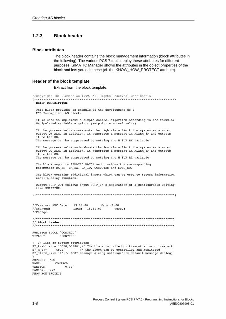
Block attributes The block header contains the block management information (block attributes in the following). The various PCS 7 tools deploy these attributes for different purposes. SIMATIC Manager shows the attributes in the object properties of the block and lets you edit these (cf. the KNOW_HOW_PROTECT attribute).
Header of the block template Extract from the block template:
//Copyright (C) Siemens AG 1999. All Rights Reserved. Confidential (****************************************************************************** BRIEF DESCRIPTION: This block provides an example of the development of a PCS 7-compliant AS block. It is used to implement a simple control algorithm according to the formula: Manipulated variable = gain * (setpoint - actual value) If the process value overshoots the high alarm limit the system sets error output QH_ALM. In addition, it generates a message in ALARM_8P and outputs it to the OS. The message can be suppressed by setting the M_SUP_AH variable. If the process value undershoots the low alarm limit the system sets error output QL_ALM. In addition, it generates a message in ALARM_8P and outputs it to the OS. The message can be suppressed by setting the M_SUP_AL variable. The block supports SIMATIC BATCH and provides the corresponding parameters BA_EN, BA_NA, BA_ID, OCCUPIED and STEP_NO. The block contains additional inputs which can be used to return information about a delay function: Output SUPP_OUT follows input SUPP_IN o expiration of a configurable Waiting time SUPPTIME. ..****************************************************************************) //Creator: ABC Date: 13.08.00 Vers.:1.00 //Changed: Date: 18.11.03 Vers.: //Change: //**************************************************************************** // Block header //**************************************************************************** FUNCTION_BLOCK "CONTROL" TITLE = 'CONTROL' { // List of system attributes S7_tasklist:= 'OB80,OB100';// The block is called on timeout error or restart S7_m_c:= 'true'; // The block can be controlled and monitored S7_alarm_ui:= '1' // PCS7 message dialog setting('0'= default message dialog) } AUTHOR: ABC NAME: CONTROL VERSION: '0.02' FAMILY: XYZ KNOW_HOW_PROTECT

Creating AS blocks
Process Control System PCS 7 V7.0 - Programming Instructions for Blocks A5E00807905-01 1-9
Object properties of the compiled block template The screenshots below show the object properties of the compiled block template, including cross-references to the relevant attributes of the block header.
FUNCTION_BLOCK
TITLE
Fig. 1-2: Object properties of the block (General - part 1)
Creating AS blocks
Process Control System PCS 7 V7.0 - Programming Instructions for Blocks 1-10 A5E00807905-01
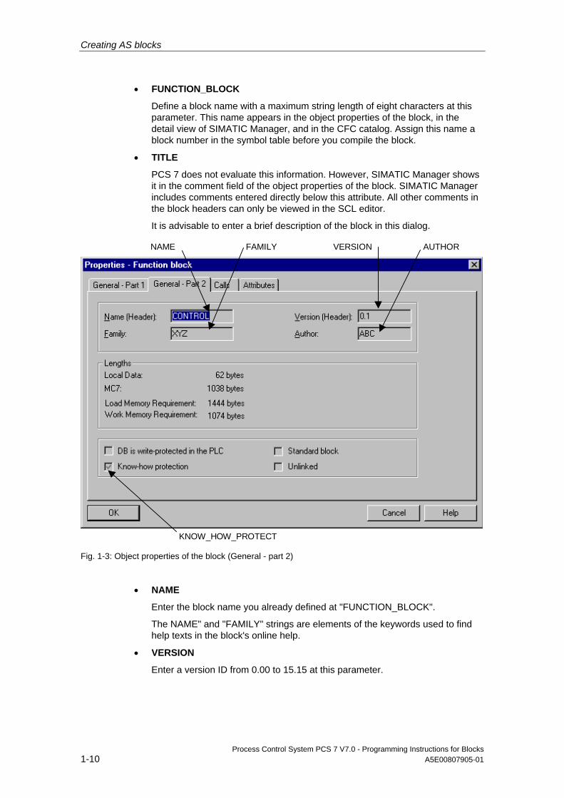
• FUNCTION_BLOCK
Define a block name with a maximum string length of eight characters at this parameter. This name appears in the object properties of the block, in the detail view of SIMATIC Manager, and in the CFC catalog. Assign this name a block number in the symbol table before you compile the block.
• TITLE
PCS 7 does not evaluate this information. However, SIMATIC Manager shows it in the comment field of the object properties of the block. SIMATIC Manager includes comments entered directly below this attribute. All other comments in the block headers can only be viewed in the SCL editor.
It is advisable to enter a brief description of the block in this dialog.
NAME
KNOW_HOW_PROTECT
FAMILY VERSION AUTHOR
Fig. 1-3: Object properties of the block (General - part 2)
• NAME
Enter the block name you already defined at "FUNCTION_BLOCK".
The NAME" and "FAMILY" strings are elements of the keywords used to find help texts in the block's online help.
• VERSION
Enter a version ID from 0.00 to 15.15 at this parameter.
Creating AS blocks
Process Control System PCS 7 V7.0 - Programming Instructions for Blocks A5E00807905-01 1-11
• FAMILY
Enter a group name for the block at this parameter when collecting your blocks in a user-specific library and assigning these to different groups. Enter a name with a maximum string length of eight characters
The "NAME" and "FAMILY" strings are elements of the keywords used to find help texts in the block's online help (cf. chapter 3.3).
• AUTHOR
This attribute usually contains the name or department of the block's creator. The attribute is also used for two other functions at PCS 7-compliant blocks:
- Enter a name shared by all blocks you want to group in your library Enter a name with a maximum string length of eight characters
- This name is used to find the relevant help file in the online help system
• KNOW_HOW_PROTECT
You can read and write protect the block algorithm and attributes by setting this attribute. Effects of this attribute:
- It sets the read only flag for the block attributes in the object properties dialog of the block in SIMATIC Manager
- Offline of the project and if the corresponding source code is not available you can only open the block in the STL editor. You can no longer open it in SCL. Only the block parameters are displayed The SCL Compiler is started within your project
Creating AS blocks
Process Control System PCS 7 V7.0 - Programming Instructions for Blocks 1-12 A5E00807905-01
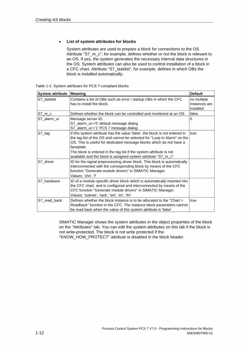
• List of system attributes for blocks
System attributes are used to prepare a block for connections to the OS. Attribute "S7_m_c", for example, defines whether or not the block is relevant to an OS. If yes, the system generates the necessary internal data structures in the OS. System attributes can also be used to control installation of a block in a CFC chart. Attribute "S7_tasklist", for example, defines in which OBs the block is installed automatically.
Table 1-1: System attributes for PCS 7-compliant blocks
System attribute Meaning Default S7_tasklist Contains a list of OBs such as error / startup OBs in which the CFC
has to install the block. no multiple instances are installed
S7_m_c Defines whether the block can be controlled and monitored at an OS. false S7_alarm_ui Message server ID:
S7_alarm_ui:='0' default message dialog S7_alarm_ui:='1' PCS 7 message dialog
0
S7_tag If this system attribute has the value 'false', the block is not entered in the tag list of the OS and cannot be selected for "Loop in Alarm" on the OS. This is useful for dedicated message blocks which do not have a faceplate. The block is entered in the tag list if the system attribute is not available and the block is assigned system attribute "S7_m_c".
true
S7_driver ID for the signal preprocessing driver block. This block is automatically interconnected with the corresponding block by means of the CFC function "Generate module drivers" in SIMATIC Manager. Values: 'chn', 'f'
S7_hardware ID of a module-specific driver block which is automatically inserted into the CFC chart, and is configured and interconnected by means of the CFC function "Generate module drivers" in SIMATIC Manager. Values: 'subnet', 'rack', 'sm', 'im', 'fm'
S7_read_back Defines whether the block instance is to be allocated to the "Chart > Readback" function in the CFC. The instance block parameters cannot be read back when the value of this system attribute is 'false'.
true
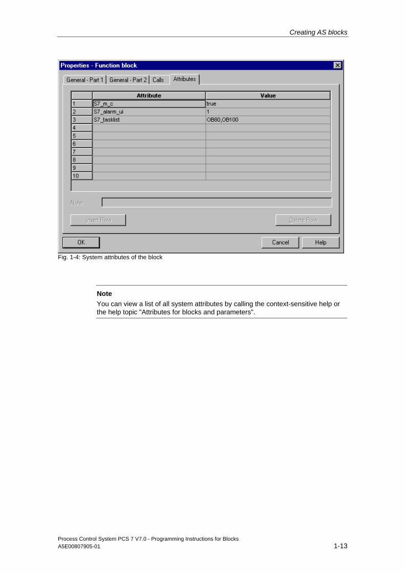
SIMATIC Manager shows the system attributes in the object properties of the block on the "Attributes" tab. You can edit the system attributes on this tab if the block is not write-protected. The block is not write protected if the "KNOW_HOW_PROTECT" attribute is disabled in the block header.
Creating AS blocks
Process Control System PCS 7 V7.0 - Programming Instructions for Blocks A5E00807905-01 1-13
Fig. 1-4: System attributes of the block
Note
You can view a list of all system attributes by calling the context-sensitive help or the help topic "Attributes for blocks and parameters".
Creating AS blocks
Process Control System PCS 7 V7.0 - Programming Instructions for Blocks 1-14 A5E00807905-01
1.2.4 Declaration section
1.2.4.1 Block parameters
Block interface The block's parameters define its interface to other blocks and to control and monitoring tools such as CFC and WinCC.
Parameter types Parameter types available:
• Input parameters
Operations for which input parameter functions must be declared for PCS 7-compliant blocks:
- You want to fetch parameter values from another block
- You want to control parameters at the OS
- You want to define visualization of a faceplate on the OS with the help of parameters. Example: range limits of the views.
- You want to be able to manipulate parameters in CFC for test purposes
- You need parameters such as Message Event-ID of the ALARM_8P block to generate messages
- If you require bumpless changeovers between input values from the program (CPU) and control values entered by the operator (OS), the input parameters can be read back and written back (see in/out parameters) by the block algorithm. By contrast to the in/out parameters, the input parameters are not written back to the interconnected output parameters
• Output parameters
Operations for which output parameters must be declared for PCS 7-compliant blocks:
- You want to transfer parameter values to another block
- You want to monitor parameters at the OS
- You want to monitor parameters in CFC when running tests
Creating AS blocks
Process Control System PCS 7 V7.0 - Programming Instructions for Blocks A5E00807905-01 1-15
• In/out parameters
In/out parameters can be read back and written back by the block algorithm. In/out parameters must be declared for PCS 7-compliant blocks when you require a bumpless changeover between input values from the program (AS) and manipulated values (OS). You need three parameters to implement this functionality:
- One input parameter for changeover
- One input parameter for the interconnected value
- One in/out parameter for the manipulated value This must be an in/out parameter, as the interconnected value must be written back to the manipulated value This method ensures the bumpless changeover from the interconnected to the manipulated value
Comments for parameters In order to add comments to the block parameters, append the separator "//" to the parameter definition and then enter your comments.
Comments are displayed in the CFC chart in the object properties of the I/O and in the object properties of the block in the "Inputs/Outputs" tab. You can edit the comments on this tab, irrespective whether or not the "KNOW_HOW_PROTECT" attribute has been set in the block header.
System attributes for parameters Similar to the block declaration, you can enhance your block parameter declaration using system attributes.
Definitions in particular:
• Representation of the parameter on the OS Example: "S7_unit" defines the parameter unit such as "liter". You can view the text defined at this attribute in your faceplate.
• Whether and how the parameter is handled in CFC Example: "S7_visible" defines whether or not the parameter is displayed in the CFC chart
Creating AS blocks
Process Control System PCS 7 V7.0 - Programming Instructions for Blocks 1-16 A5E00807905-01
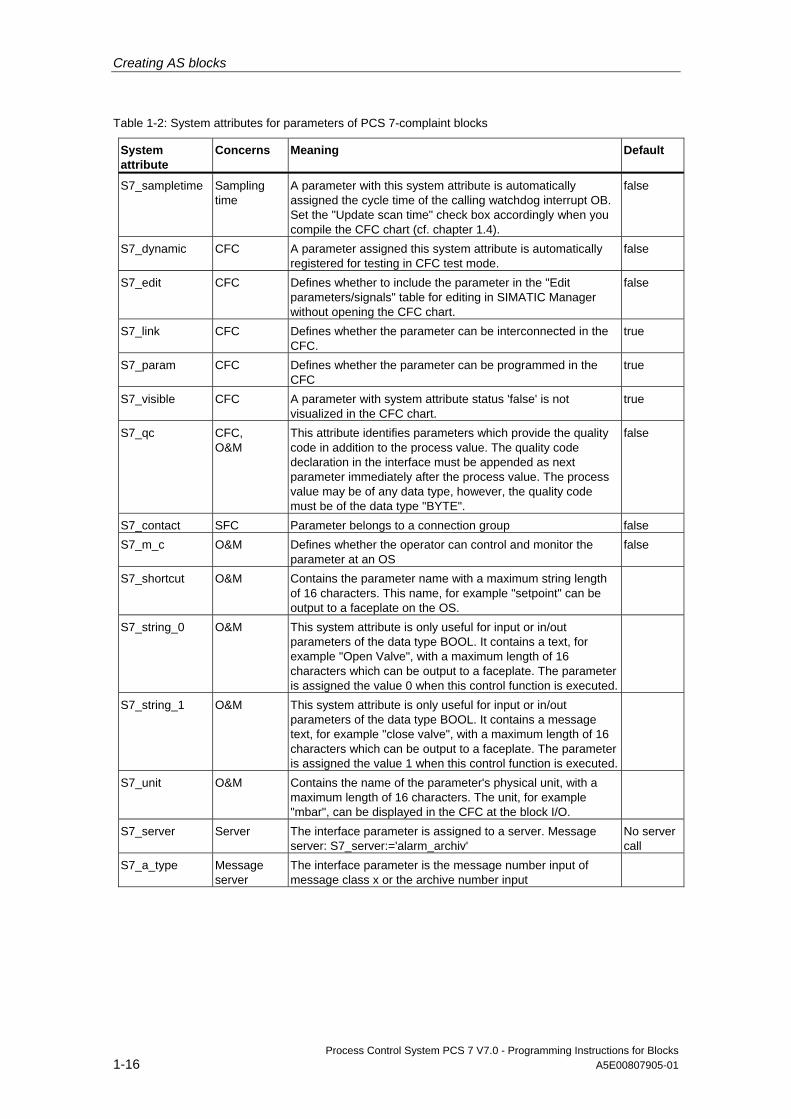
Table 1-2: System attributes for parameters of PCS 7-complaint blocks
System attribute
Concerns Meaning Default
S7_sampletime Sampling time
A parameter with this system attribute is automatically assigned the cycle time of the calling watchdog interrupt OB. Set the "Update scan time" check box accordingly when you compile the CFC chart (cf. chapter 1.4).
false
S7_dynamic CFC A parameter assigned this system attribute is automatically registered for testing in CFC test mode.
false
S7_edit CFC Defines whether to include the parameter in the "Edit parameters/signals" table for editing in SIMATIC Manager without opening the CFC chart.
false
S7_link CFC Defines whether the parameter can be interconnected in the CFC.
true
S7_param CFC Defines whether the parameter can be programmed in the CFC
true
S7_visible CFC A parameter with system attribute status 'false' is not visualized in the CFC chart.
true
S7_qc CFC, O&M
This attribute identifies parameters which provide the quality code in addition to the process value. The quality code declaration in the interface must be appended as next parameter immediately after the process value. The process value may be of any data type, however, the quality code must be of the data type "BYTE".
false
S7_contact SFC Parameter belongs to a connection group false S7_m_c O&M Defines whether the operator can control and monitor the
parameter at an OS false
S7_shortcut O&M Contains the parameter name with a maximum string length of 16 characters. This name, for example "setpoint" can be output to a faceplate on the OS.
S7_string_0 O&M This system attribute is only useful for input or in/out parameters of the data type BOOL. It contains a text, for example "Open Valve", with a maximum length of 16 characters which can be output to a faceplate. The parameter is assigned the value 0 when this control function is executed.
S7_string_1 O&M This system attribute is only useful for input or in/out parameters of the data type BOOL. It contains a message text, for example "close valve", with a maximum length of 16 characters which can be output to a faceplate. The parameter is assigned the value 1 when this control function is executed.
S7_unit O&M Contains the name of the parameter's physical unit, with a maximum length of 16 characters. The unit, for example "mbar", can be displayed in the CFC at the block I/O.
S7_server Server The interface parameter is assigned to a server. Message server: S7_server:='alarm_archiv'
No server call
S7_a_type Message server
The interface parameter is the message number input of message class x or the archive number input
Creating AS blocks
Process Control System PCS 7 V7.0 - Programming Instructions for Blocks A5E00807905-01 1-17
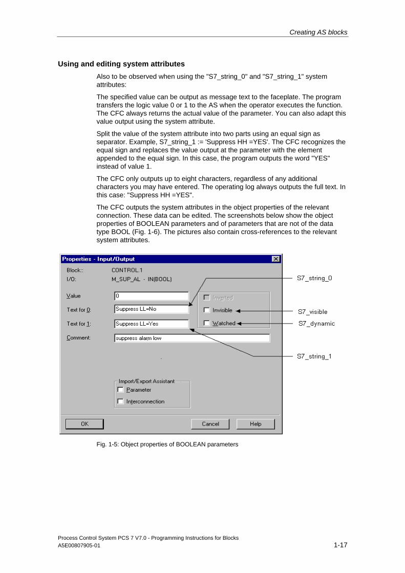
Using and editing system attributes Also to be observed when using the "S7_string_0" and "S7_string_1" system attributes:
The specified value can be output as message text to the faceplate. The program transfers the logic value 0 or 1 to the AS when the operator executes the function. The CFC always returns the actual value of the parameter. You can also adapt this value output using the system attribute.
Split the value of the system attribute into two parts using an equal sign as separator. Example, S7_string_1 := 'Suppress HH =YES'. The CFC recognizes the equal sign and replaces the value output at the parameter with the element appended to the equal sign. In this case, the program outputs the word "YES" instead of value 1.
The CFC only outputs up to eight characters, regardless of any additional characters you may have entered. The operating log always outputs the full text. In this case: "Suppress HH =YES".
The CFC outputs the system attributes in the object properties of the relevant connection. These data can be edited. The screenshots below show the object properties of BOOLEAN parameters and of parameters that are not of the data type BOOL (Fig. 1-6). The pictures also contain cross-references to the relevant system attributes.
Fig. 1-5: Object properties of BOOLEAN parameters

Creating AS blocks
Process Control System PCS 7 V7.0 - Programming Instructions for Blocks 1-18 A5E00807905-01
Fig. 1-6: Object properties of non-BOOLEAN parameters
Creating AS blocks
Process Control System PCS 7 V7.0 - Programming Instructions for Blocks A5E00807905-01 1-19
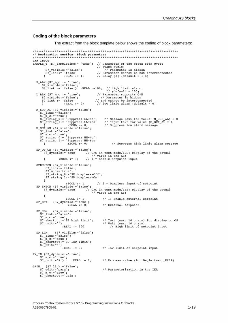
Coding of the block parameters The extract from the block template below shows the coding of block parameters:
//***************************************************************************** // Declaration section: Block parameters //***************************************************************************** VAR_INPUT SAMPLE_T {S7_sampletime:= 'true'; // Parameter of the block scan cycle // (Task cycle) S7_visible:='false'; // Parameter is hidden S7_link:= 'false' // Parameter cannot be not interconnected } :REAL := 1; // Delay [s] (default = 1 s) H_ALM {S7_m_c := 'true'; S7_visible:='false'; S7_link := 'false'} :REAL :=100; // high limit alarm // (default = 100) L_ALM {S7_m_c := 'true'; // Parameter supports O&M S7_visible:='false'; // Parameter is hidden S7_link := 'false' // and cannot be interconnected } :REAL := 0; // low limit alarm (default = 0) M_SUP_AL {S7_visible:='false'; S7_link:='false'; S7_m_c:='true'; S7_string_0:= 'Suppress LL=No'; // Message text for value (M_SUP_AL) = 0 S7_string_1:= 'Suppress LL=Yes' // Input text for value (M_SUP_AL)= 1 } :BOOL := 0; // Suppress low alarm message M_SUP_AH {S7_visible:='false'; S7_link:='false'; S7_m_c:='true'; S7_string_0:= 'Suppress HH=No'; S7_string_1:= 'Suppress HH=Yes' } :BOOL := 0; // Suppress high limit alarm message SP_OP_ON {S7_visible:='false'; S7_dynamic:='true' // CFC in test mode/IBS: Display of the actual // value in the AS) } :BOOL := 1; // 1 = enable setpoint input SPBUMPON {S7_visible:='false'; S7_link:='false'; S7_m_c:='true'; S7_string_0:='SP bumpless=Off'; S7_string_1:='SP bumpless=On' } :BOOL := 1; // 1 = bumpless input of setpoint SP_EXTON {S7_visible:='false'; S7_dynamic:='true' // CFC in test mode/IBS: Display of the actual // value in the AS) } :BOOL := 1; // 1: Enable external setpoint SP_EXT {S7_dynamic:='true'} :REAL := 0; // External setpoint SP_HLM {S7_visible:='false'; S7_link:='false'; S7_m_c:='true'; S7_shortcut:='SP high limit'; // Text (max. 16 chars) for display on OS S7_unit:=''} // Unit (max. 16 chars) :REAL := 100; // High limit of setpoint input SP_LLM {S7_visible:='false'; S7_link:='false'; S7_m_c:='true'; S7_shortcut:='SP low limit'; S7_unit:=''} :REAL := 0; // low limit of setpoint input PV_IN {S7_dynamic:='true'; S7_m_c:='true'; S7_unit:='%'} : REAL := 0; // Process value (for Begleitwert_PR04) GAIN {S7_link:='false'; S7_edit:='para'; // Parameterization in the IEA S7_m_c:='true'; S7_shortcut:='Gain';

Creating AS blocks
Process Control System PCS 7 V7.0 - Programming Instructions for Blocks 1-20 A5E00807905-01
S7_unit:=''} :REAL := 1; // Proportional gain EV_ID {S7_visible:='false'; S7_link:='false'; S7_param :='false'; // Parameter cannot be programmed in CFC S7_server:='alarm_archiv'; // Message no. assigned by server S7_a_type:='alarm_8p' // Block reports with ALARM_8P } :DWORD := 0; // Message number // Parameters for SIMATIC BATCH STEP_NO {S7_visible := 'false'; S7_m_c := 'true'} :DWORD; // Batch step number BA_ID {S7_visible := 'false'; S7_m_c := 'true'} :DWORD; // Consecutive batch number BA_EN {S7_visible := 'false'; // Parameter hidden in CFC chart S7_m_c := 'true' // Parameter supports O&M } :BOOL := 0; // Batch busy enable BA_NA {S7_visible := 'false'; S7_m_c := 'true'} :STRING[32] := ''; // Batch name OCCUPIED {S7_visible := 'false'; S7_m_c := 'true'} :BOOL := 0; // Batch busy ID RUNUPCYC {S7_visible:='false'; S7_link:='false'} :INT := 3; // Number of initial startup cycles SUPPTIME :REAL := 0; // Delay time SUPP_IN :REAL := 0; // Input value for delay time END_VAR VAR_OUTPUT LMN {S7_shortcut:='pressure'; // Name of the parameter on OS S7_unit := '%'; // Unit of the parameter S7_m_c := 'true' // monitoring supported } :REAL; // Manipulated value output QH_ALM :BOOL := false; // 1 = high limit alarm triggered QL_ALM :BOOL := false; // 1 = low limit alarm triggered QSP_HLM {S7_visible:='false'; S7_dynamic:='true'} : BOOL := 0; // 1= Setpoint output high limit // is active QSP_LLM {S7_visible:='false'; S7_dynamic:='true'} : BOOL := 0; // 1=Setpoint output low limit // is active Q_SP_OP {S7_visible:='false'; S7_dynamic:='true'; S7_m_c:='true'} : BOOL := 0; // Status: 1 = Setpoint input enabled QOP_ERR {S7_visible:='false'; S7_dynamic:='true'} : BOOL := 0; // 1 = operator error QMSG_ERR {S7_visible:='false'; S7_dynamic:='true'} : BOOL := 0; // ALARM_8P: Message error MSG_STAT {S7_visible:='false'; S7_dynamic:='true'} : WORD := 0; // Message error information MSG_ACK {S7_visible:='false'; S7_dynamic:='true'} : WORD := 0; // Acknowledge messages SUPP_OUT :REAL := 0; // Output value for delay SP {S7_dynamic:='true'; S7_m_c:='true'} : REAL := 0; // Active setpoint END_VAR VAR_IN_OUT SP_OP {S7_visible:='false'; S7_link:='false'; S7_m_c:='true'; S7_shortcut:='Setpoint'; S7_unit:='%'} : REAL := 0; // Input of setpoint // user-specific associated message values of ALARM_8P AUX_PR05 {S7_visible := 'false'} : ANY; // Associated value 5 AUX_PR06 {S7_visible := 'false'} : ANY; // Associated value 6 AUX_PR07 {S7_visible := 'false'} : ANY; // Associated value 7 AUX_PR08 {S7_visible := 'false'} : ANY; // Associated value 8 AUX_PR09 {S7_visible := 'false'} : ANY; // Associated value 9 AUX_PR10 {S7_visible := 'false'} : ANY; // Associated value 10

Creating AS blocks
Process Control System PCS 7 V7.0 - Programming Instructions for Blocks A5E00807905-01 1-21
END_VAR
Creating AS blocks
Process Control System PCS 7 V7.0 - Programming Instructions for Blocks 1-22 A5E00807905-01
1.2.4.2 Local variables Additional variables which are not output as block parameters to external functions must be declared as local variables.
There are two types of local variables:
• Static variables
• Temporary variables
Static variables By contrast to temporary variables, the static variables retain their values across several block calls. The value only changes when you edit it in the block algorithm.
These variables are of particular importance in PCS 7-compliant blocks if you want to call either your own or default blocks within your block. In this case you should implement a multiple instance block. This can be done by declaring an instance of the called block within the static variable.
The called blocks must exist in the block folder of the S7 program in order to successfully compile the calling block.
If you want to visualize and interconnect parameters of the called block, you must copy these from your block algorithm or into parameters of your block. The parameters of the called block itself are not visible to external functions.
Multiple instances
You will find examples of multiple instance applications in the chapter dealing with CFC block types and in the relevant SCL code of the sample project.
Note
Called SFBs and SFCs, such as SFC 6 (RD_SINFO) or SFB 0 (CTU) are found automatically in the standard library and are written to your S7 program when you compile the calling block.
If the called FBs and the calling block are available in the same library, the program copies the called FBs to the block folder when you install the calling block in a CFC chart. You will otherwise have to copy the blocks manually.

Creating AS blocks
Process Control System PCS 7 V7.0 - Programming Instructions for Blocks A5E00807905-01 1-23
Temporary variables Temporary variables are valid only for the duration of one block call, i.e., they must be calculated at each new block call. There are no special features to observe for PCS 7-compliant blocks in this context. Extract from the block template:
//****************************************************************************** // Declaration section: Temporary variables //****************************************************************************** VAR_TEMP // Start info: Structure with info for the OB that has just called // the block TOP_SI: STRUCT EV_CLASS :BYTE; EV_NUM :BYTE; PRIORITY :BYTE; NUM :BYTE; TYP2_3 :BYTE; TYP1 :BYTE; ZI1 :WORD; ZI2_3 :DWORD; END_STRUCT; // Start info: Structure with info for the most recently called startup OB START_UP_SI: STRUCT EV_CLASS :BYTE; EV_NUM :BYTE; PRIORITY :BYTE; NUM :BYTE; TYP2_3 :BYTE; TYP1 :BYTE; ZI1 :WORD; ZI2_3 :DWORD; END_STRUCT; S7DT :DATE_AND_TIME; // Local time variable DUMMY :INT; // Associated variable END_VAR

Creating AS blocks
Process Control System PCS 7 V7.0 - Programming Instructions for Blocks 1-24 A5E00807905-01
1.2.5 Code section
The code section contains the actual block algorithm. This allows you to implement the following features for PCS 7-compliant blocks:
• The technological functions of the block
• Block properties which can be used, for example, to report asynchronous events and the block states to the OS, and to visualize these using a faceplate of a WinCC message list
Creating AS blocks
Process Control System PCS 7 V7.0 - Programming Instructions for Blocks A5E00807905-01 1-25
1.3 Initialization
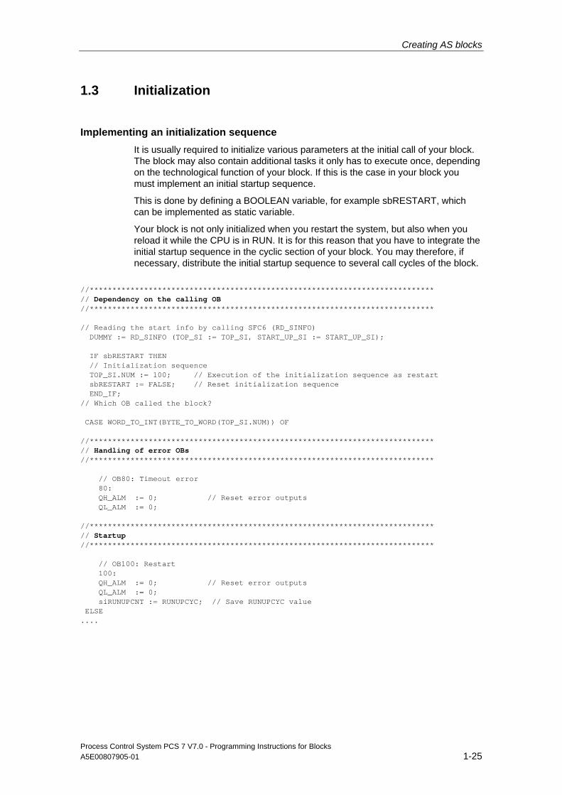
Implementing an initialization sequence It is usually required to initialize various parameters at the initial call of your block. The block may also contain additional tasks it only has to execute once, depending on the technological function of your block. If this is the case in your block you must implement an initial startup sequence.
This is done by defining a BOOLEAN variable, for example sbRESTART, which can be implemented as static variable.
Your block is not only initialized when you restart the system, but also when you reload it while the CPU is in RUN. It is for this reason that you have to integrate the initial startup sequence in the cyclic section of your block. You may therefore, if necessary, distribute the initial startup sequence to several call cycles of the block.
//**************************************************************************** // Dependency on the calling OB //**************************************************************************** // Reading the start info by calling SFC6 (RD_SINFO) DUMMY := RD_SINFO (TOP_SI := TOP_SI, START_UP_SI := START_UP_SI); IF sbRESTART THEN // Initialization sequence TOP_SI.NUM := 100; // Execution of the initialization sequence as restart sbRESTART := FALSE; // Reset initialization sequence END_IF; // Which OB called the block? CASE WORD_TO_INT(BYTE_TO_WORD(TOP_SI.NUM)) OF //**************************************************************************** // Handling of error OBs //**************************************************************************** // OB80: Timeout error 80: QH_ALM := 0; // Reset error outputs QL_ALM := 0; //**************************************************************************** // Startup //**************************************************************************** // OB100: Restart 100: QH_ALM := 0; // Reset error outputs QL_ALM := 0; siRUNUPCNT := RUNUPCYC; // Save RUNUPCYC value ELSE ....
Creating AS blocks
Process Control System PCS 7 V7.0 - Programming Instructions for Blocks 1-26 A5E00807905-01
1.4 Time dependency
Programming a time dependency Define an input parameter of data type REAL, for example SAMPLE_T, if the conditions shown below apply to your block:
• It is processed within a constant time-out level
• The block has to evaluate the length of the time interval in order to execute time-sensitive tasks, for example, for controller blocks
The length of the time interval can be declared at this input parameter.
Program this parameter to synchronize it with the watchdog interrupt OB in which your block is called. This ensures that your block algorithm is always executed within the correct time.
The CFC automatically sets a parameter value matching the calling OB if you set system attribute "S7_sampletime" = 'true' at the parameter. The program also makes allowances for any reduction of the ratio. Assign the "S7_visible" and "S7_link" system attributes to the parameter as well and set their status to 'false'. This setting hides the parameter in the CFC and prevents its interconnection in order to avoid unintentional manipulation of its value by the user.
However, the CFC can only automatically assign values to this parameter if the "Update sampling time" check box is set when you compile the program.

Creating AS blocks
Process Control System PCS 7 V7.0 - Programming Instructions for Blocks A5E00807905-01 1-27
Implementing the time dependency The next extract of the block template shows you how to implement such a time dependency. You can program a waiting time at the block by setting the SUPPTIME parameter. Changes at input SUPP_IN are transferred to output SUPP_OUT on expiration of this waiting time.
/***************************************************************************** // Declaration section: Block parameters //**************************************************************************** VAR_INPUT SAMPLE_T {S7_sampletime:= 'true' // Parameter block scan cycle // (Task cycle) S7_visible:='false'; // Parameter is hidden S7_link:= 'false' // Parameter cannot be not interconnected } :REAL := 1; // Delay time [s] (default = 1 s) .... END_VAR //**************************************************************************** // Declaration section: Static variables //**************************************************************************** VAR .... sSUPP_IN :REAL := 0; // Old value of sample delay input ACT_TIME :REAL := 0; // Time counter .... END_VAR VAR_OUTPUT .... SUPP_OUT :REAL := 0; // Output value for delay .... END_VAR //**************************************************************************** // Technological section //**************************************************************************** IF (SUPP_IN <> sSUPP_IN) THEN ACT_TIME := SUPPTIME; // Initialize time counter sSUPP_IN := SUPP_IN; END_IF; IF (ACT_TIME > 0) THEN // If waiting time has not yet expired ACT_TIME := ACT_TIME-SAMPLE_T; // count down waiting time ELSE SUPP_OUT := SUPP_IN; // Transfer input value to output END_IF; ....
Creating AS blocks
Process Control System PCS 7 V7.0 - Programming Instructions for Blocks 1-28 A5E00807905-01
1.5 Handling asynchronous startup and error OBs
Asynchronous event The AS calls an asynchronous OB when asynchronous events such as restart, removal/insertion and rack failure are detected. If your block has to react to such events, install it in the corresponding OB and program the block algorithm for detection of these events.
Installation in asynchronous OBs Use system attribute "S7_tasklist" to install your block in specific OBs. Enter all OB values required. Example: S7_tasklist: = 'OB80,OB100'. The CFC installs the block in the current watchdog interrupt OB and in all OBs defined at "S7_tasklist" when you insert the block into a CFC chart.
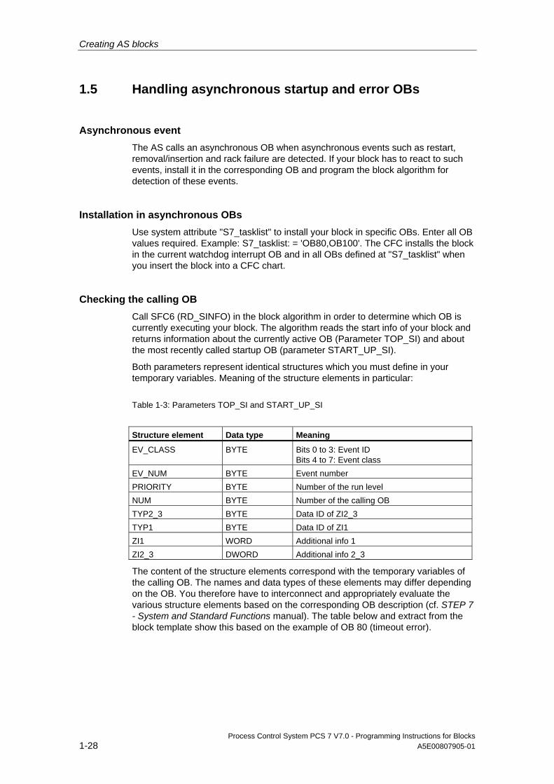
Checking the calling OB Call SFC6 (RD_SINFO) in the block algorithm in order to determine which OB is currently executing your block. The algorithm reads the start info of your block and returns information about the currently active OB (Parameter TOP_SI) and about the most recently called startup OB (parameter START_UP_SI).
Both parameters represent identical structures which you must define in your temporary variables. Meaning of the structure elements in particular:
Table 1-3: Parameters TOP_SI and START_UP_SI
Structure element Data type Meaning
EV_CLASS BYTE Bits 0 to 3: Event ID Bits 4 to 7: Event class
EV_NUM BYTE Event number PRIORITY BYTE Number of the run level NUM BYTE Number of the calling OB TYP2_3 BYTE Data ID of ZI2_3 TYP1 BYTE Data ID of ZI1 ZI1 WORD Additional info 1 ZI2_3 DWORD Additional info 2_3
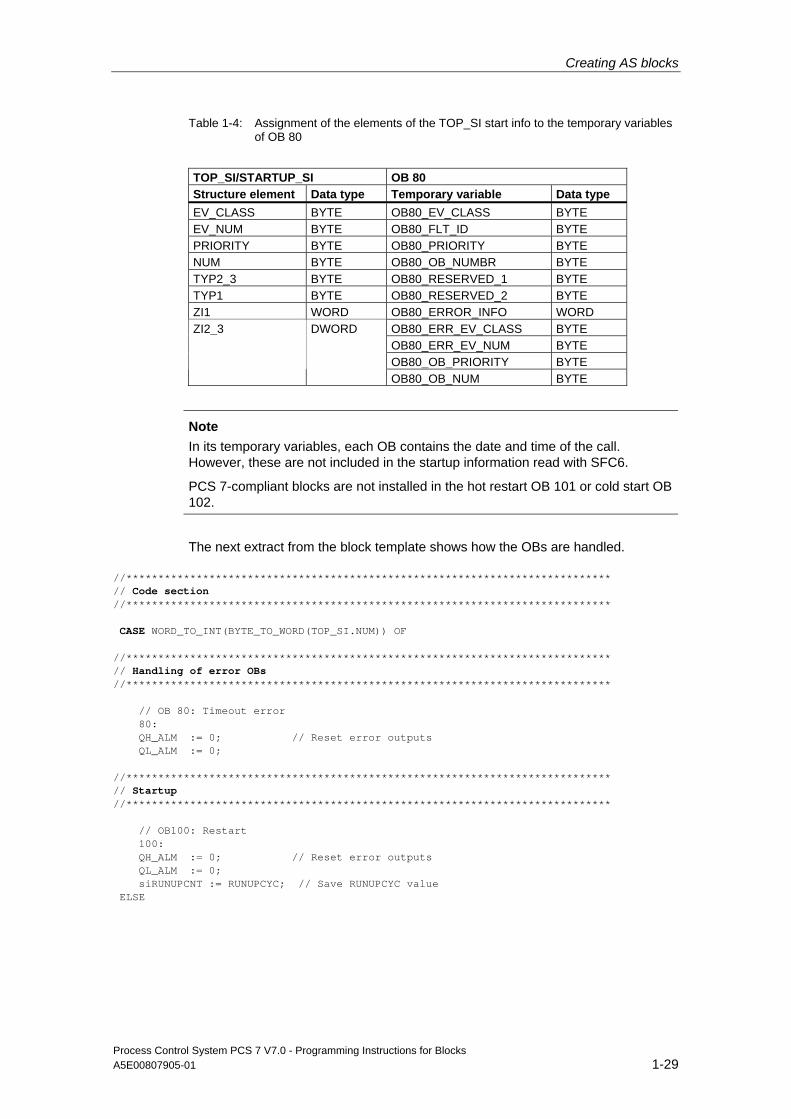
The content of the structure elements correspond with the temporary variables of the calling OB. The names and data types of these elements may differ depending on the OB. You therefore have to interconnect and appropriately evaluate the various structure elements based on the corresponding OB description (cf. STEP 7 - System and Standard Functions manual). The table below and extract from the block template show this based on the example of OB 80 (timeout error).
Creating AS blocks
Process Control System PCS 7 V7.0 - Programming Instructions for Blocks A5E00807905-01 1-29
Table 1-4: Assignment of the elements of the TOP_SI start info to the temporary variables of OB 80
TOP_SI/STARTUP_SI OB 80 Structure element Data type Temporary variable Data type EV_CLASS BYTE OB80_EV_CLASS BYTE EV_NUM BYTE OB80_FLT_ID BYTE PRIORITY BYTE OB80_PRIORITY BYTE NUM BYTE OB80_OB_NUMBR BYTE TYP2_3 BYTE OB80_RESERVED_1 BYTE TYP1 BYTE OB80_RESERVED_2 BYTE ZI1 WORD OB80_ERROR_INFO WORD
OB80_ERR_EV_CLASS BYTE OB80_ERR_EV_NUM BYTE OB80_OB_PRIORITY BYTE
ZI2_3 DWORD
OB80_OB_NUM BYTE
Note
In its temporary variables, each OB contains the date and time of the call. However, these are not included in the startup information read with SFC6.
PCS 7-compliant blocks are not installed in the hot restart OB 101 or cold start OB 102.
The next extract from the block template shows how the OBs are handled.
//**************************************************************************** // Code section //**************************************************************************** CASE WORD_TO_INT(BYTE_TO_WORD(TOP_SI.NUM)) OF //**************************************************************************** // Handling of error OBs //**************************************************************************** // OB 80: Timeout error 80: QH_ALM := 0; // Reset error outputs QL_ALM := 0; //**************************************************************************** // Startup //**************************************************************************** // OB100: Restart 100: QH_ALM := 0; // Reset error outputs QL_ALM := 0; siRUNUPCNT := RUNUPCYC; // Save RUNUPCYC value ELSE
Creating AS blocks
Process Control System PCS 7 V7.0 - Programming Instructions for Blocks 1-30 A5E00807905-01
1.6 Operating, monitoring and reporting
Operating and monitoring A block must be interconnected with the OS in order to be able to operate and monitor its parameters at the OS. This concerns both the required parameters and the actual block.
Operator control functions If you want to manipulate a parameter value only at the OS you need to install an in/out or input parameter with system attribute "S7_m_c" for this manipulated value.
If, on the other hand, you need an option of either fetching a parameter value from another block or setting the value at the OS and change over from the interconnected to the manipulated value in a bumpless operation, you require altogether three parameters:
• One input parameter for toggling between manipulated and interconnected values
• One input parameter for the interconnected value
• One in/out parameter with system attribute "S7_m_c" for the manipulated value This must be an in/out parameter, because the block algorithm has to write back the interconnected value to the manipulated value as long as the interconnected value is selected in order to obtain a bumpless changeover.
Use the control blocks of the "PCS 7 Library V70" and their corresponding control method for all operator control functions on the OS. This integrates all interlocks, including the optional bumpless changeover between the manipulated and interconnected value required, for example, for toggling the manual/auto modes. You can install these control blocks in your block using the multiple instance technique.
Blocks for limiting input operations PCS 7 provides the following block for limiting input operations:
• OP_A_LIM (operation analog limited)
• OP_A_RJC: Rejects the input operation if limits are violated
• OP_A Use this block if you decide to discard limit monitoring
Note The AS block and the faceplate interact in asynchronous mode, i.e. a value input at the faceplate is written to the instance DB of the AS block and evaluated by this AS block at a later time. As the relevant limits may already have changed at this point in time, the manipulated value should be checked for errors both on the AS and on the OS.

Creating AS blocks
Process Control System PCS 7 V7.0 - Programming Instructions for Blocks A5E00807905-01 1-31
Blocks for binary input The PCS 7 Library V61 provides the OP_D (FB 48), OP_D3 (FB 49) and OP_TRIG (FB 50) blocks for binary input. For further information, refer to the Online Help.
Input definition The extract below shows an input definition:
//**************************************************************************** // Input of the setpoint SP_OP (REAL value) or of the interconnected // setpoint SP_EXT //**************************************************************************** // Multiple instance call OP_A_LIM (for information on the meaning of the // parameters, refer to the Online Help OP_A_LIM) OP_A_LIM_1(U := SP_OP, U_HL:= SP_HLM, U_LL:= SP_LLM, OP_EN:= SP_OP_ON, BTRACK:= SPBUMPON, LINK_ON:= SP_EXTON, LINK_U:= SP_EXT); OK := OK AND ENO; //Accept Enable Out of OP_A_LIM in OK flag of the block // Q_SP_OP := OP_A_LIM_1.QOP_EN; // 1: Enable SP input QOP_ERR := OP_A_LIM_1.QOP_ERR; // 1: Input error QSP_HLM := OP_A_LIM_1.QVHL; // 1: High limit QSP_LLM := OP_A_LIM_1.QVLL; // 1: Low limit SP := OP_A_LIM_1.V; // effective setpoint
Messages You can define a multiple instance of an alarm block in the static variables to enable the output of messages and/or events to the OS at your block. The message and acknowledgment reactions, including the transfer of associated values, are determined by the properties of the CPU (selectable acknowledgment-triggered reporting) and of the integrated alarm block.
The "Standard Library" contains alarm block templates in the form of SFBs. Blocks included, for example: ALARM SFB 33 Monitors a signal with 1 to 10 associated values with confirmation
prompt ALARM_8 SFB 34 Monitors up to 8 signals
ALARM_8P SFB 35 Monitors up to 8 signals with 1 to 10 associated values
NOTIFY SFB 36 Monitors a signal with 1 to 10 associated values without
confirmation prompt NOTIFY_8P SFB 31 Monitors up to 8 signals with 1 to 10 associated values without
confirmation prompt
Creating AS blocks
Process Control System PCS 7 V7.0 - Programming Instructions for Blocks 1-32 A5E00807905-01
Block header entries In order to enable manipulation and/or monitoring of the block on the OS, set system attribute "S7_m_c" = 'true' at the block header in the list of system attributes.
Set attribute S7_alarm_ui := '1' at the block header in order to enable the call of the PCS 78 message dialog in SIMATIC Manager. The value '0' returns the STEP 7-compliant dialog.
Entries in the declaration section In order to enable manipulation and monitoring of your block parameters on the OS, set system attribute "S7_m_c" = 'true' at each block parameter you want to control and monitor.
You enable the output of messages and/or events to the OS at your block by defining an input of the data type DWORD (here: EV_ID). In the instance DB, this input accepts the message number automatically assigned by the system (message server).
The message number must be unique throughout the S7 project in order to avoid conflicts in projects containing several AS and OS. The numbers for individual messages required in WinCC are derived from this message number during data transfer (compile OS).
At this input, enter system attribute "S7_server" with the value 'alarm_archiv' and system attribute "S7_a_type" with the value 'alarm_8p', or a value according to the message block you installed. The input should not be visible in the CFC chart and it should not be possible to interconnect or assign parameters to the input in order to avoid any unintentional manipulation of data assigned by the system.
Creating AS blocks
Process Control System PCS 7 V7.0 - Programming Instructions for Blocks A5E00807905-01 1-33
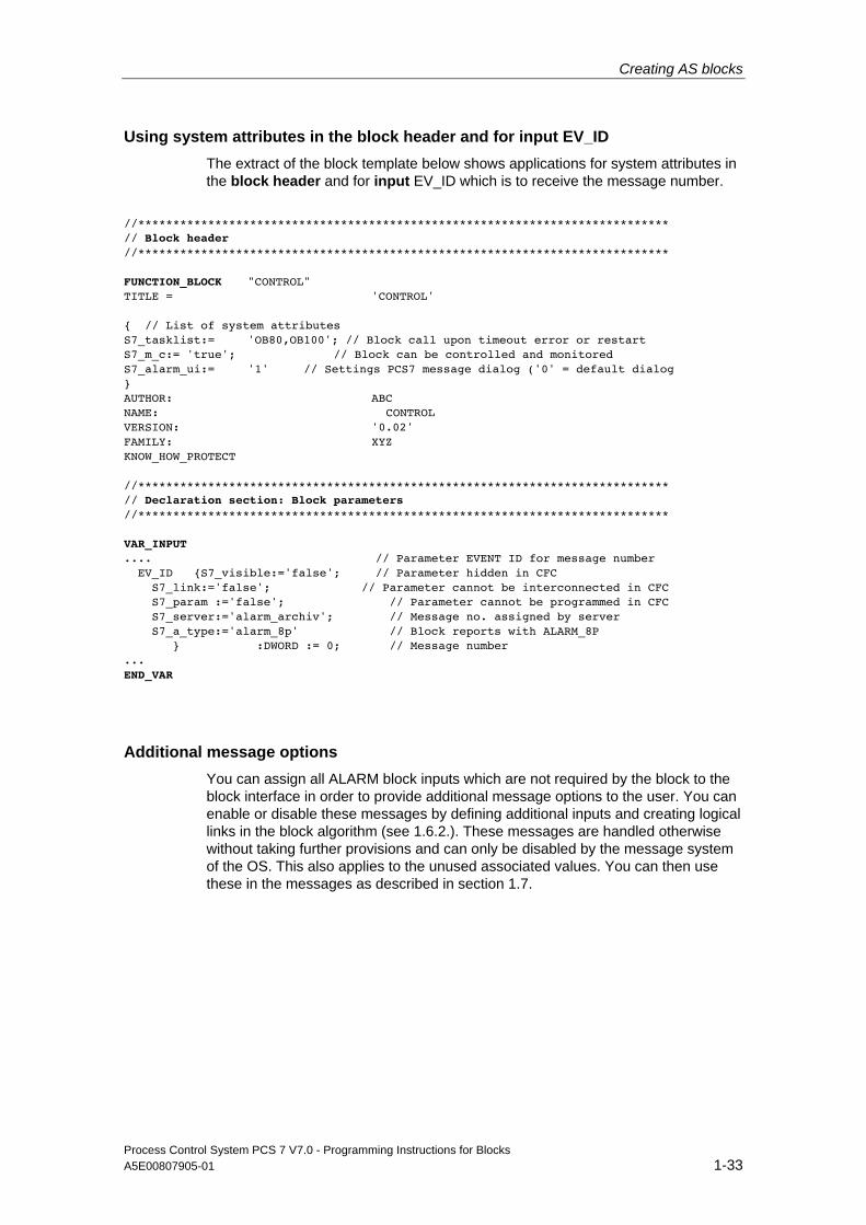
Using system attributes in the block header and for input EV_ID The extract of the block template below shows applications for system attributes in the block header and for input EV_ID which is to receive the message number.
//**************************************************************************** // Block header //**************************************************************************** FUNCTION_BLOCK "CONTROL" TITLE = 'CONTROL' { // List of system attributes S7_tasklist:= 'OB80,OB100'; // Block call upon timeout error or restart S7_m_c:= 'true'; // Block can be controlled and monitored S7_alarm_ui:= '1' // Settings PCS7 message dialog ('0' = default dialog } AUTHOR: ABC NAME: CONTROL VERSION: '0.02' FAMILY: XYZ KNOW_HOW_PROTECT //**************************************************************************** // Declaration section: Block parameters //**************************************************************************** VAR_INPUT .... // Parameter EVENT ID for message number EV_ID {S7_visible:='false'; // Parameter hidden in CFC S7_link:='false'; // Parameter cannot be interconnected in CFC S7_param :='false'; // Parameter cannot be programmed in CFC S7_server:='alarm_archiv'; // Message no. assigned by server S7_a_type:='alarm_8p' // Block reports with ALARM_8P } :DWORD := 0; // Message number ... END_VAR
Additional message options You can assign all ALARM block inputs which are not required by the block to the block interface in order to provide additional message options to the user. You can enable or disable these messages by defining additional inputs and creating logical links in the block algorithm (see 1.6.2.). These messages are handled otherwise without taking further provisions and can only be disabled by the message system of the OS. This also applies to the unused associated values. You can then use these in the messages as described in section 1.7.
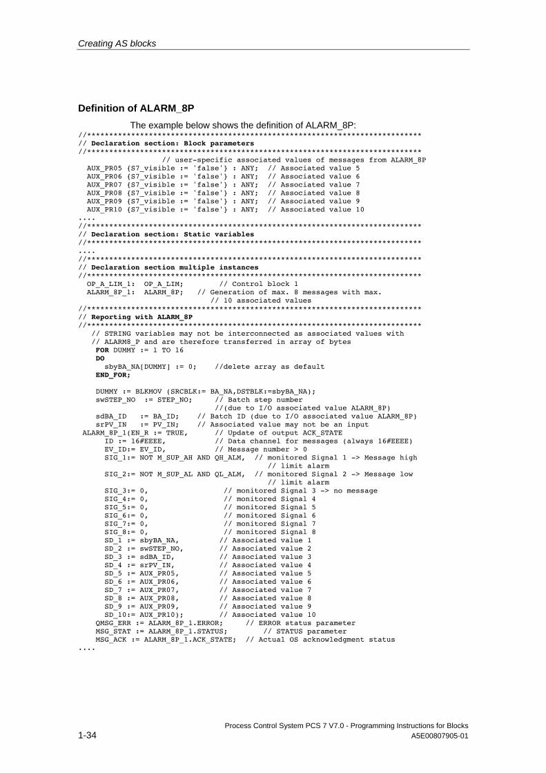
Creating AS blocks
Process Control System PCS 7 V7.0 - Programming Instructions for Blocks 1-34 A5E00807905-01
Definition of ALARM_8P The example below shows the definition of ALARM_8P:
//**************************************************************************** // Declaration section: Block parameters //**************************************************************************** // user-specific associated values of messages from ALARM_8P AUX_PR05 {S7_visible := 'false'} : ANY; // Associated value 5 AUX_PR06 {S7_visible := 'false'} : ANY; // Associated value 6 AUX_PR07 {S7_visible := 'false'} : ANY; // Associated value 7 AUX_PR08 {S7_visible := 'false'} : ANY; // Associated value 8 AUX_PR09 {S7_visible := 'false'} : ANY; // Associated value 9 AUX_PR10 {S7_visible := 'false'} : ANY; // Associated value 10 .... //**************************************************************************** // Declaration section: Static variables //**************************************************************************** .... //**************************************************************************** // Declaration section multiple instances //**************************************************************************** OP_A_LIM_1: OP_A_LIM; // Control block 1 ALARM_8P_1: ALARM_8P; // Generation of max. 8 messages with max. // 10 associated values //**************************************************************************** // Reporting with ALARM_8P //**************************************************************************** // STRING variables may not be interconnected as associated values with // ALARM8_P and are therefore transferred in array of bytes FOR DUMMY := 1 TO 16 DO sbyBA_NA[DUMMY] := 0; //delete array as default END_FOR; DUMMY := BLKMOV (SRCBLK:= BA_NA,DSTBLK:=sbyBA_NA); swSTEP_NO := STEP_NO; // Batch step number //(due to I/O associated value ALARM_8P) sdBA_ID := BA_ID; // Batch ID (due to I/O associated value ALARM_8P) srPV_IN := PV_IN; // Associated value may not be an input ALARM_8P_1(EN_R := TRUE, // Update of output ACK_STATE ID := 16#EEEE, // Data channel for messages (always 16#EEEE) EV_ID:= EV_ID, // Message number > 0 SIG_1:= NOT M_SUP_AH AND QH_ALM, // monitored Signal 1 -> Message high // limit alarm SIG_2:= NOT M_SUP_AL AND QL_ALM, // monitored Signal 2 -> Message low // limit alarm SIG_3:= 0, // monitored Signal 3 -> no message SIG_4:= 0, // monitored Signal 4 SIG_5:= 0, // monitored Signal 5 SIG_6:= 0, // monitored Signal 6 SIG_7:= 0, // monitored Signal 7 SIG_8:= 0, // monitored Signal 8 SD_1 := sbyBA_NA, // Associated value 1 SD_2 := swSTEP_NO, // Associated value 2 SD_3 := sdBA_ID, // Associated value 3 SD_4 := srPV_IN, // Associated value 4 SD_5 := AUX_PR05, // Associated value 5 SD_6 := AUX_PR06, // Associated value 6 SD_7 := AUX_PR07, // Associated value 7 SD_8 := AUX_PR08, // Associated value 8 SD_9 := AUX_PR09, // Associated value 9 SD_10:= AUX_PR10); // Associated value 10 QMSG_ERR := ALARM_8P_1.ERROR; // ERROR status parameter MSG_STAT := ALARM_8P_1.STATUS; // STATUS parameter MSG_ACK := ALARM_8P_1.ACK_STATE; // Actual OS acknowledgment status ....
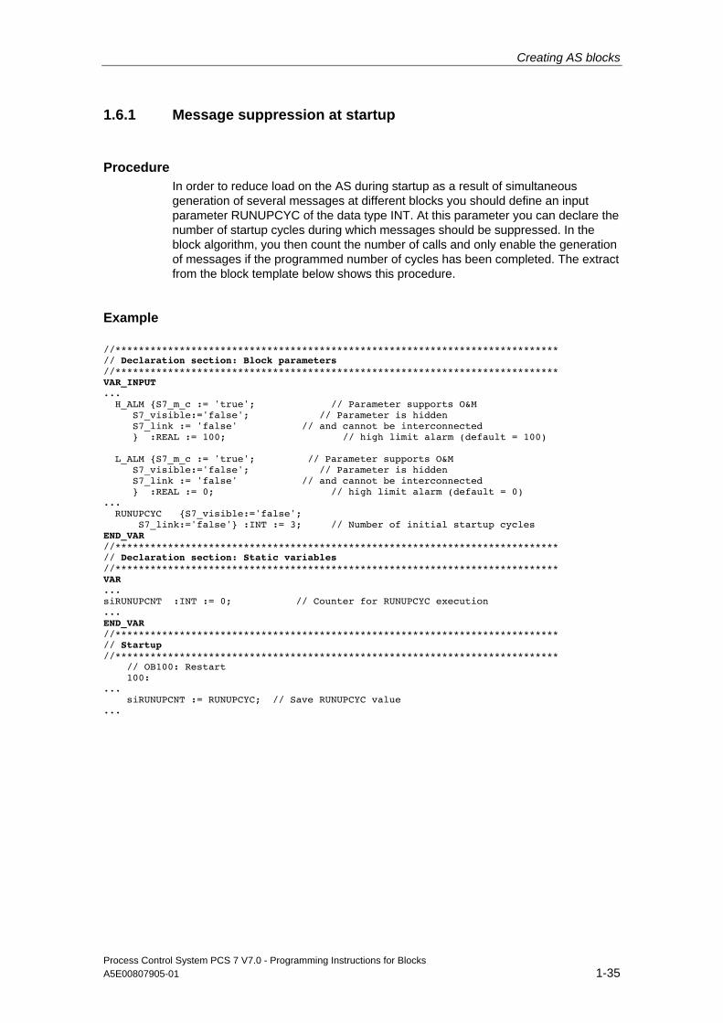
Creating AS blocks
Process Control System PCS 7 V7.0 - Programming Instructions for Blocks A5E00807905-01 1-35
1.6.1 Message suppression at startup
Procedure In order to reduce load on the AS during startup as a result of simultaneous generation of several messages at different blocks you should define an input parameter RUNUPCYC of the data type INT. At this parameter you can declare the number of startup cycles during which messages should be suppressed. In the block algorithm, you then count the number of calls and only enable the generation of messages if the programmed number of cycles has been completed. The extract from the block template below shows this procedure.
Example
//**************************************************************************** // Declaration section: Block parameters //**************************************************************************** VAR_INPUT ... H_ALM {S7_m_c := 'true'; // Parameter supports O&M S7_visible:='false'; // Parameter is hidden S7_link := 'false' // and cannot be interconnected } :REAL := 100; // high limit alarm (default = 100) L_ALM {S7_m_c := 'true'; // Parameter supports O&M S7_visible:='false'; // Parameter is hidden S7_link := 'false' // and cannot be interconnected } :REAL := 0; // high limit alarm (default = 0) ... RUNUPCYC {S7_visible:='false'; S7_link:='false'} :INT := 3; // Number of initial startup cycles END_VAR //**************************************************************************** // Declaration section: Static variables //**************************************************************************** VAR ... siRUNUPCNT :INT := 0; // Counter for RUNUPCYC execution ... END_VAR //**************************************************************************** // Startup //**************************************************************************** // OB100: Restart 100: ... siRUNUPCNT := RUNUPCYC; // Save RUNUPCYC value ...
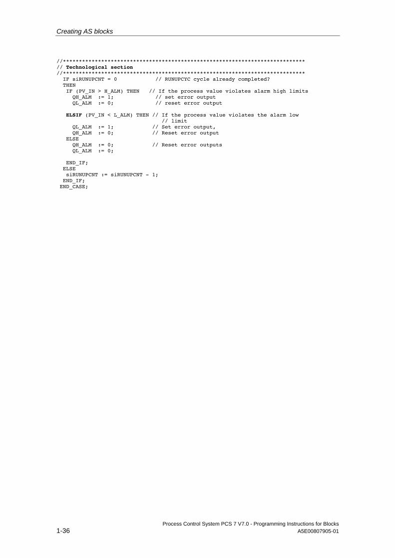
Creating AS blocks
Process Control System PCS 7 V7.0 - Programming Instructions for Blocks 1-36 A5E00807905-01
//**************************************************************************** // Technological section //**************************************************************************** IF siRUNUPCNT = 0 // RUNUPCYC cycle already completed? THEN IF (PV_IN > H_ALM) THEN // If the process value violates alarm high limits QH_ALM := 1; // set error output QL_ALM := 0; // reset error output ELSIF (PV_IN < L_ALM) THEN // If the process value violates the alarm low // limit QL_ALM := 1; // Set error output, QH_ALM := 0; // Reset error output ELSE QH_ALM := 0; // Reset error outputs QL_ALM := 0; END_IF; ELSE siRUNUPCNT := siRUNUPCNT - 1; END_IF; END_CASE;
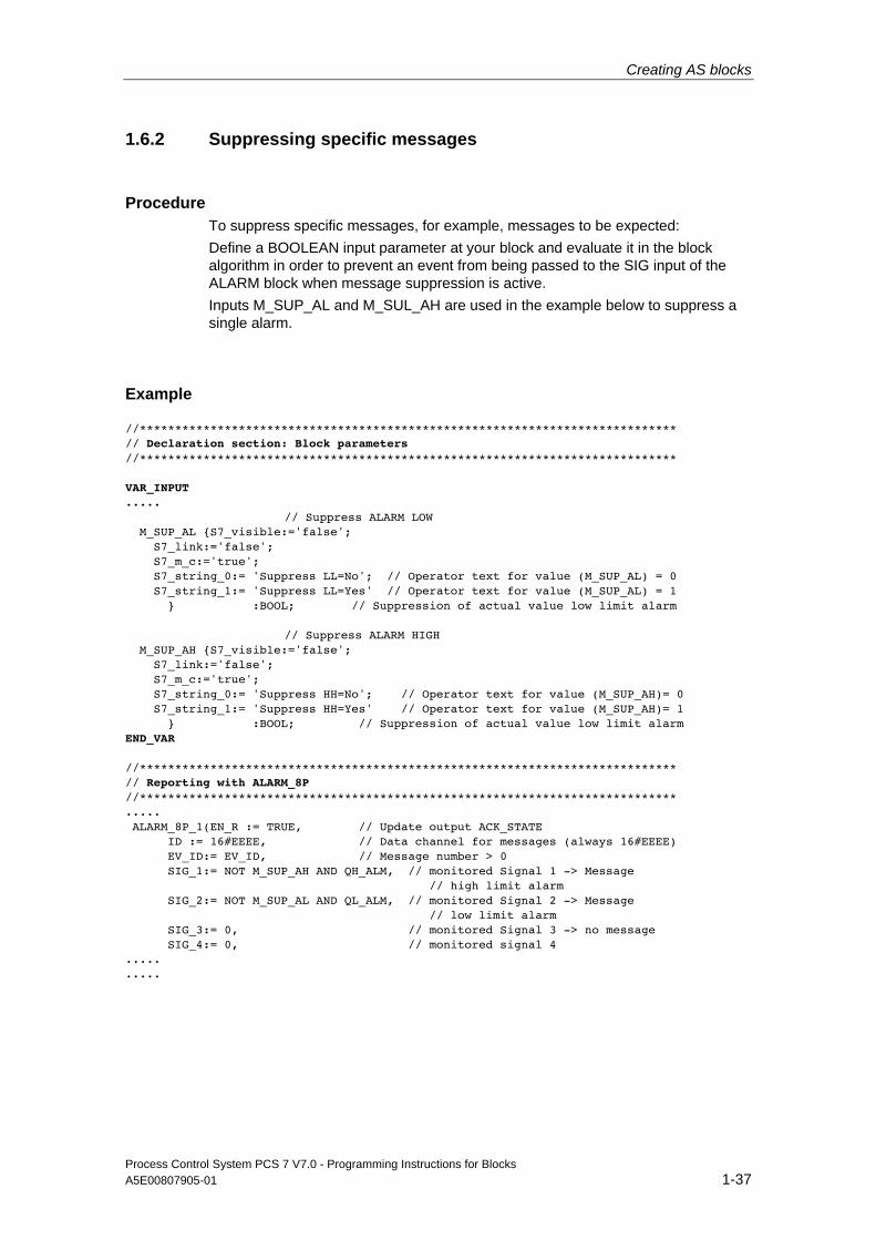
Creating AS blocks
Process Control System PCS 7 V7.0 - Programming Instructions for Blocks A5E00807905-01 1-37
1.6.2 Suppressing specific messages
Procedure To suppress specific messages, for example, messages to be expected: Define a BOOLEAN input parameter at your block and evaluate it in the block algorithm in order to prevent an event from being passed to the SIG input of the ALARM block when message suppression is active. Inputs M_SUP_AL and M_SUL_AH are used in the example below to suppress a single alarm.
Example
//**************************************************************************** // Declaration section: Block parameters //**************************************************************************** VAR_INPUT ..... // Suppress ALARM LOW M_SUP_AL {S7_visible:='false'; S7_link:='false'; S7_m_c:='true'; S7_string_0:= 'Suppress LL=No'; // Operator text for value (M_SUP_AL) = 0 S7_string_1:= 'Suppress LL=Yes' // Operator text for value (M_SUP_AL) = 1 } :BOOL; // Suppression of actual value low limit alarm // Suppress ALARM HIGH M_SUP_AH {S7_visible:='false'; S7_link:='false'; S7_m_c:='true'; S7_string_0:= 'Suppress HH=No'; // Operator text for value (M_SUP_AH)= 0 S7_string_1:= 'Suppress HH=Yes' // Operator text for value (M_SUP_AH)= 1 } :BOOL; // Suppression of actual value low limit alarm END_VAR //**************************************************************************** // Reporting with ALARM_8P //**************************************************************************** ..... ALARM_8P_1(EN_R := TRUE, // Update output ACK_STATE ID := 16#EEEE, // Data channel for messages (always 16#EEEE) EV_ID:= EV_ID, // Message number > 0 SIG_1:= NOT M_SUP_AH AND QH_ALM, // monitored Signal 1 -> Message // high limit alarm SIG_2:= NOT M_SUP_AL AND QL_ALM, // monitored Signal 2 -> Message // low limit alarm SIG_3:= 0, // monitored Signal 3 -> no message SIG_4:= 0, // monitored signal 4 ..... .....
Creating AS blocks
Process Control System PCS 7 V7.0 - Programming Instructions for Blocks 1-38 A5E00807905-01
1.6.3 Compiling the source code
When you have completed programming, compile the source code using the SCL Compiler. Select File > Compile. You can also click the corresponding toolbar icon.
FB 501 is available in the block folder of the S7 program after you successfully completed compilation.
For further information, refer to the "S7-SCL for S7-300 and S7-400" manual.
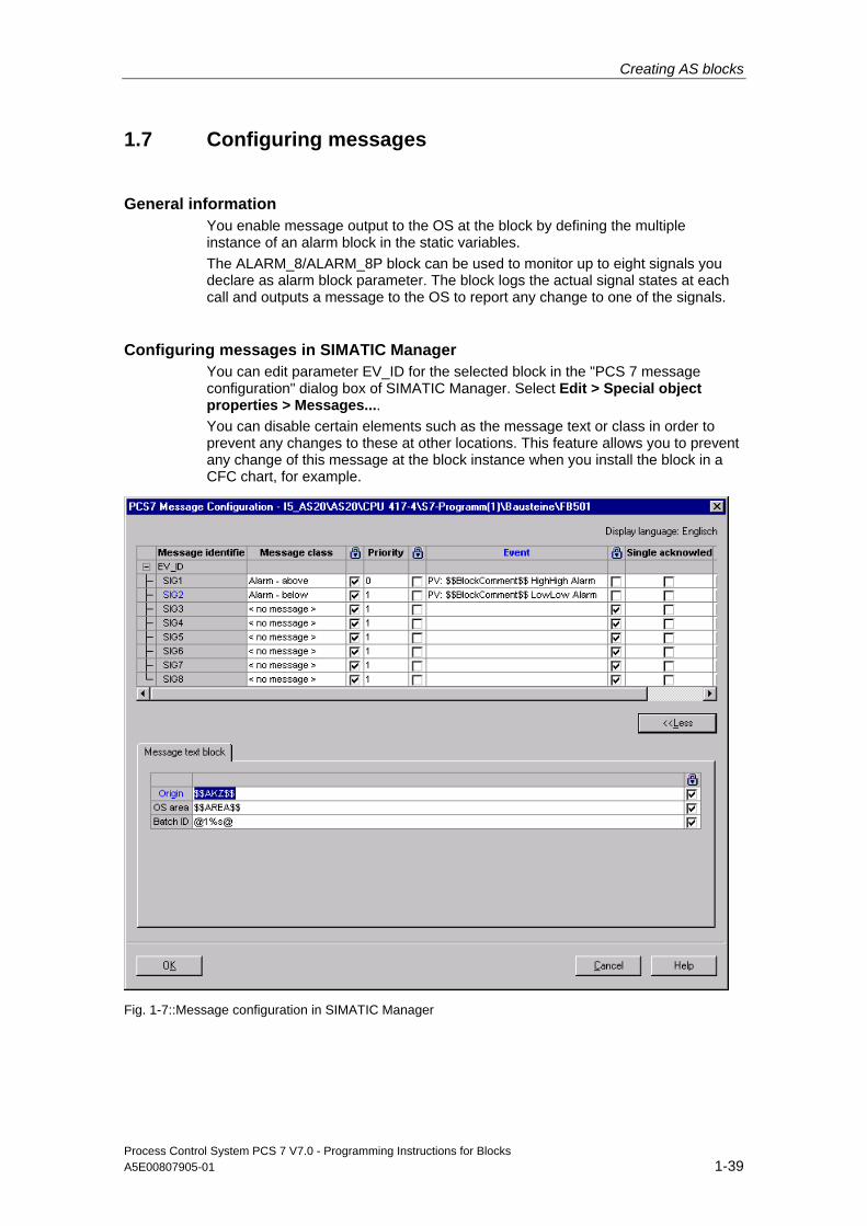
Creating AS blocks
Process Control System PCS 7 V7.0 - Programming Instructions for Blocks A5E00807905-01 1-39
1.7 Configuring messages
General information You enable message output to the OS at the block by defining the multiple instance of an alarm block in the static variables. The ALARM_8/ALARM_8P block can be used to monitor up to eight signals you declare as alarm block parameter. The block logs the actual signal states at each call and outputs a message to the OS to report any change to one of the signals.
Configuring messages in SIMATIC Manager You can edit parameter EV_ID for the selected block in the "PCS 7 message configuration" dialog box of SIMATIC Manager. Select Edit > Special object properties > Messages.... You can disable certain elements such as the message text or class in order to prevent any changes to these at other locations. This feature allows you to prevent any change of this message at the block instance when you install the block in a CFC chart, for example.
Fig. 1-7::Message configuration in SIMATIC Manager
Creating AS blocks
Process Control System PCS 7 V7.0 - Programming Instructions for Blocks 1-40 A5E00807905-01
Start by entering the global message texts for this block. The individual texts correspond to the user text blocks in AlarmLogging of WinCC.
Origin Define the message origin at this parameter. If you enter the origin keyword $$AKZ$$ the program initiates the following actions when you transfer the data: When you compile the OS, the program determines the path of the hierarchy folder, the chart name and the block name, and saves these to the OS message texts.
Note The TH path is only entered if the name is derived from the relevant hierarchy folders (properties of the THF or TH settings).
OS area Define the message area at this parameter. If you enter the area keyword $$AREA$$ or leave a blank input box, the program initiates the following actions when you transfer the data: When you compile the OS, the program evaluates the corresponding attribute of the hierarchy folder and saves it to the OS message texts.
Batch ID You can define a batch ID for the message at this parameter. If you enter the batch ID the program initiates the following actions when you transfer the data: It evaluates the corresponding attribute and writes it to the "Charge name" column of the WinCC message list when you compile the OS. However, instead of the batch ID, this entry represents the batch name. Enter the value @1%s@ if your block is to be compatible with the optional S7 package SIMATIC BATCH. This function assigns the BATCH charge identifier as initial associated value to the message (cf. chapter 1.8). If you do not use SIMATIC BATCH, do not make any entry here.
Creating AS blocks
Process Control System PCS 7 V7.0 - Programming Instructions for Blocks A5E00807905-01 1-41
Message classes Define the corresponding message classes in the next step. Click in a corresponding message row in the "Message class" column to transform this into a combo box in which you can select the message class. Assign all unused messages the "< no message >" class. For detailed information on handling messages, refer to the WinCC documentation. Settings to be made:
• Enter a description of the error cause in the "Event" column The text length should not exceed 40 characters, including any associated values
• Define these functions in the "Single acknowledgment" column:
- Set the check box to activate separate acknowledgment of messages
- Reset the check box to enable group acknowledgment for the message
• Define these properties at the "Locked" (blue lock icon) column:
- Deactivate the check box in order to allow instance-specific modification of the message class in the CFC by the block users
- Activate the check box in order to prevent changes to the message class
Priority You can assign different message priorities in this dialog.
Properties you can define at the "Locked" (blue lock icon) column:
• Deactivate the check box in order to allow instance-specific modification of the priority class in the CFC by the block users
• Activate the check box in order to prevent changes to the priority class
Event Enter a message text in this input box.

Creating AS blocks
Process Control System PCS 7 V7.0 - Programming Instructions for Blocks 1-42 A5E00807905-01
Associated values for messages In order to include additional information such as measured values in the message frame output to the OS, integrate an ALARM message block which supports the definition of associated values (ALARM_8P = 10 associated values). The values transferred at the SD_1 to SD_10 parameters of the ALARM block can be included in the message texts in the following format:
@ Parameter number format instruction @
In the next example, the value defined at parameter SD_4 is output in decimal format. The supported format instructions correspond with the C syntax.
@4%d@
You can include the block instance comment in the message text by entering the keyword $$BlockComment$$.
At the "Locked" column (blue lock icon), you define whether to allow (check box deactivated) or lock (check box activated) instance-specific modification of the message text in the CFC by the user of the block.
Note
The associated values of an ALARM_8P are of data type ANY, connection type I/O. The data types supported for associated values are listed in the ALARM_8P Online Help. If you define the associated values as an input and not as an I/O in the block interface, you have to save the associated values to a variable in the VAR section and transfer this variable as an associated value with ALARM_8P.
The data type STRING may not be transferred as an associated value. You have to implement it as in the block template, by copying it to an ARRAY OF BYTE and transferring this ARRAY as an associated value.
Single acknowledgment Activate the check box if the message is to be acknowledged separately.
Info text Enter an info text in this field.

Creating AS blocks
Process Control System PCS 7 V7.0 - Programming Instructions for Blocks A5E00807905-01 1-43
1.8 Integration of SIMATIC BATCH
Definition of input and in/out parameters Input or in/out parameters to be defined when using your blocks with the optional S7 package "SIMATIC BATCH":
Parameter name Meaning Parameter type Data type
BA_EN BATCH busy enable INPUT BOOL BA_NA BATCH name INPUT STRING[32] BA_ID Consecutive batch number INPUT DWORD OCCUPIED BATCH busy ID INPUT BOOL STEP_NO BATCH step number INPUT DWORD
Extract from the block template:
//**************************************************************************** // Declaration section: Block parameters //**************************************************************************** VAR_INPUT .... // Parameters for SIMATIC BATCH STEP_NO {S7_visible := 'false'; S7_m_c := 'true'} :DWORD; // Batch step number BA_ID {S7_visible := 'false'; S7_m_c := 'true'} :DWORD; // Consecutive batch number BA_EN {S7_visible := 'false'; // Parameter hidden in CFC chart S7_m_c := 'true' // Parameter supports O&M } :BOOL := 0; // Batch busy enable BA_NA {S7_visible := 'false'; S7_m_c := 'true'} :STRING[32] := ''; // Batch name OCCUPIED {S7_visible := 'false'; S7_m_c := 'true'} :BOOL := 0; // Batch busy ID .... END_VAR
Generating messages In order to generate messages in a block of this type you need to implement inputs BA_NA, STEP_NO and BA_ID as associated message values in the given order.
The associated values are used as shown below: Associated value Meaning
1 BATCH name BA_NA 2 BATCH step number STEP_NO 3 BATCH: consecutive batch number BA_ID
4 to 7 Block-specific assignment or user-specific
Creating AS blocks
Process Control System PCS 7 V7.0 - Programming Instructions for Blocks 1-44 A5E00807905-01
1.9 Creating CFC block types
1.9.1 CFC
By contrast to CFC which is based on the interconnection of graphical objects, SCL involves the declaration of variables and programming of assignments. CFC supports the development of new blocks by means of the insertion and interconnection of existing blocks.
The overview in the next section is focused on functions and basic procedures. For details on the creation of block in CFC, refer to the CFC for S7 manual and to the CFC Online Help system.
1.9.2 Example: CONTROL2
Task The "CONTROL" block template is to be expanded by integrating a multiplier. The product of the multiplication of the input values "IN1" and "IN2" forms the actual value. The expanded block is to be generated as CONTROL2 (FB 601).
Procedure 1. Open a new CFC chart and then insert the "CONTROL" block template
2. Drag-and-drop a MUL_R (FC 63) multiplier from the CFC Library\ELEMENTA to the chart
3. Interconnect output "OUT" of MUL_R with the process value (parameter "PV_IN") of the block template
4. Select the View > Chart connectors command in the chart The interface editor opens
You can also click this toolbar icon: .
5. Select the "IN" symbol on the left pane of the "Chart connectors" window
6. Interconnect "IN1" and "IN2" of MUL_R with the chart connectors Drag-and-drop the block connector to the chart connector in the pane on the right side
7. Select the Object properties > Tab: Connectors > Column: Hidden > Reset set connections to show all connections at the CONTROL block, with the exception of EN and ENO which were previously hidden
8. Interconnect all visible connectors, with the exception of the already interconnected actual value, with the chart connectors of the CFC chart
Creating AS blocks
Process Control System PCS 7 V7.0 - Programming Instructions for Blocks A5E00807905-01 1-45
9. Settings required to compile the CFC chart as block:
- Select the Chart > Compile > Chart as block type command. A dialog box opens
- On the "General" tab, enter FB number 601. Next, configure the other properties in the corresponding fields: Symbolic name, family, author, version The name of the CFC chart is already entered in the "Name" field (header) field
- Define the block and system attributes in the "Attributes" tab as required You do not have to define system attribute "S7_tasklist" on this tab (see the installation rule below).
- Click "OK" Compilation is now started
Installation rule OBs in which the CFC block type is installed:
• Cyclic OB (OB35, for example) to be used as default setting
• Each OB listed in a task list of a sublevel block, that is, the block's task list represents the cumulative task list of all sublevel blocks The actual sublevel blocks are only called in OBs which contain these blocks in their internal task list Significance in terms of this example:
- The CONTROL block template is assigned the task list "S7_tasklist = 'OB80,OB100' "
- Multiplier MUL_R does not have a task list
- The CFC block type therefore has the task list "S7_tasklist = 'OB80,OB100' " However, OB80 and OB100 only call CONTROL, without calling MUL_R.
In order to prevent the CONTROL block from being called in OB35, you should either delete it from OB35 or move it to a different OB. The same applies to the MUL_R block.
Creating AS blocks
Process Control System PCS 7 V7.0 - Programming Instructions for Blocks 1-46 A5E00807905-01
1.10 Naming conventions and range of numbers
Range of numbers In order to prevent numbering conflicts with the PCS 7 process control blocks of Siemens, you should number the blocks starting at number 501. You should also make allowances for performance data of the CPU types supported by your library when you define the block numbers.
Names Rule for naming block parameters:
Binary outputs start with Q. Examples: QH_ALM, Q_L_ALM.
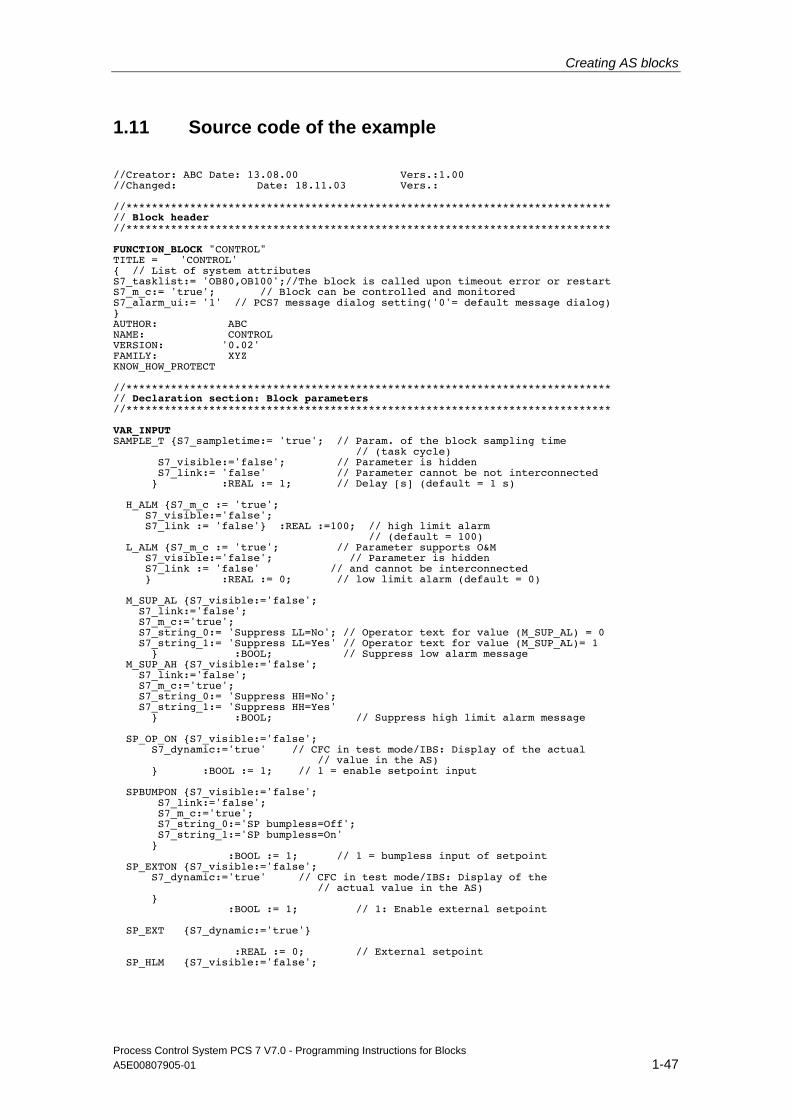
Creating AS blocks
Process Control System PCS 7 V7.0 - Programming Instructions for Blocks A5E00807905-01 1-47
1.11 Source code of the example
//Creator: ABC Date: 13.08.00 Vers.:1.00 //Changed: Date: 18.11.03 Vers.: //**************************************************************************** // Block header //**************************************************************************** FUNCTION_BLOCK "CONTROL" TITLE = 'CONTROL' { // List of system attributes S7_tasklist:= 'OB80,OB100';//The block is called upon timeout error or restart S7_m_c:= 'true'; // Block can be controlled and monitored S7_alarm_ui:= '1' // PCS7 message dialog setting('0'= default message dialog) } AUTHOR: ABC NAME: CONTROL VERSION: '0.02' FAMILY: XYZ KNOW_HOW_PROTECT //**************************************************************************** // Declaration section: Block parameters //**************************************************************************** VAR_INPUT SAMPLE_T {S7_sampletime:= 'true'; // Param. of the block sampling time // (task cycle) S7_visible:='false'; // Parameter is hidden S7_link:= 'false' // Parameter cannot be not interconnected } :REAL := 1; // Delay [s] (default = 1 s) H_ALM {S7_m_c := 'true'; S7_visible:='false'; S7_link := 'false'} :REAL :=100; // high limit alarm // (default = 100) L_ALM {S7_m_c := 'true'; // Parameter supports O&M S7_visible:='false'; // Parameter is hidden S7_link := 'false' // and cannot be interconnected } :REAL := 0; // low limit alarm (default = 0) M_SUP_AL {S7_visible:='false'; S7_link:='false'; S7_m_c:='true'; S7_string_0:= 'Suppress LL=No'; // Operator text for value (M_SUP_AL) = 0 S7_string_1:= 'Suppress LL=Yes' // Operator text for value (M_SUP_AL)= 1 } :BOOL; // Suppress low alarm message M_SUP_AH {S7_visible:='false'; S7_link:='false'; S7_m_c:='true'; S7_string_0:= 'Suppress HH=No'; S7_string_1:= 'Suppress HH=Yes' } :BOOL; // Suppress high limit alarm message SP_OP_ON {S7_visible:='false'; S7_dynamic:='true' // CFC in test mode/IBS: Display of the actual // value in the AS) } :BOOL := 1; // 1 = enable setpoint input SPBUMPON {S7_visible:='false'; S7_link:='false'; S7_m_c:='true'; S7_string_0:='SP bumpless=Off'; S7_string_1:='SP bumpless=On' } :BOOL := 1; // 1 = bumpless input of setpoint SP_EXTON {S7_visible:='false'; S7_dynamic:='true' // CFC in test mode/IBS: Display of the // actual value in the AS) } :BOOL := 1; // 1: Enable external setpoint SP_EXT {S7_dynamic:='true'} :REAL := 0; // External setpoint SP_HLM {S7_visible:='false';

Creating AS blocks
Process Control System PCS 7 V7.0 - Programming Instructions for Blocks 1-48 A5E00807905-01
S7_link:='false'; S7_m_c:='true'; S7_shortcut:='SP high limit'; // Text (max. 16 chars) for display on OS S7_unit:=''} // Unit (max. 16 chars) :REAL := 100; // High limit of setpoint input SP_LLM {S7_visible:='false'; S7_link:='false'; S7_m_c:='true'; S7_shortcut:='SP low limit'; S7_unit:=''} :REAL := 0; // low limit of setpoint input PV_IN {S7_dynamic:='true'; S7_m_c:='true'; S7_unit:='%'} : REAL := 0; // Process value (for Begleitwert_PR04) GAIN {S7_link:='false'; S7_edit:='para'; // Parameterization in the IEA S7_m_c:='true'; S7_shortcut:='Gain'; S7_unit:=''} :REAL := 1; // Proportional gain EV_ID {S7_visible:='false'; S7_link:='false'; S7_param :='false'; // Parameter cannot be programmed in CFC S7_server:='alarm_archiv'; // Message no. assigned by server S7_a_type:='alarm_8p' // Block reports with ALARM_8P } :DWORD := 0; // Message number // Parameters for SIMATIC BATCH STEP_NO {S7_visible := 'false'; S7_m_c := 'true'} :DWORD; // Batch step number BA_ID {S7_visible := 'false'; S7_m_c := 'true'} :DWORD; // Consecutive batch number BA_EN {S7_visible := 'false'; // Parameter hidden in CFC chart S7_m_c := 'true' // Parameter supports O&M } :BOOL := 0; // Batch busy enable BA_NA {S7_visible := 'false'; S7_m_c := 'true'} :STRING[32] := ''; // Batch name OCCUPIED {S7_visible := 'false'; S7_m_c := 'true'} :BOOL := 0; // Batch busy ID RUNUPCYC {S7_visible:='false'; S7_link:='false'} :INT := 3; // Number of initial startup cycles SUPPTIME :REAL := 0; // Delay time SUPP_IN :REAL := 0; // Input value for delay time END_VAR
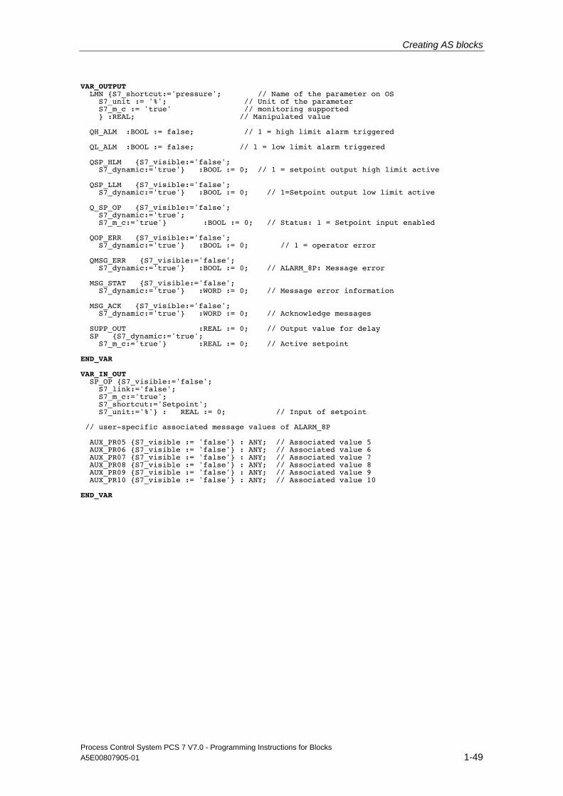
Creating AS blocks
Process Control System PCS 7 V7.0 - Programming Instructions for Blocks A5E00807905-01 1-49
VAR_OUTPUT LMN {S7_shortcut:='pressure'; // Name of the parameter on OS S7_unit := '%'; // Unit of the parameter S7_m_c := 'true' // monitoring supported } :REAL; // Manipulated value QH_ALM :BOOL := false; // 1 = high limit alarm triggered QL_ALM :BOOL := false; // 1 = low limit alarm triggered QSP_HLM {S7_visible:='false'; S7_dynamic:='true'} :BOOL := 0; // 1 = setpoint output high limit active QSP_LLM {S7_visible:='false'; S7_dynamic:='true'} :BOOL := 0; // 1=Setpoint output low limit active Q_SP_OP {S7_visible:='false'; S7_dynamic:='true'; S7_m_c:='true'} :BOOL := 0; // Status: 1 = Setpoint input enabled QOP_ERR {S7_visible:='false'; S7_dynamic:='true'} :BOOL := 0; // 1 = operator error QMSG_ERR {S7_visible:='false'; S7_dynamic:='true'} :BOOL := 0; // ALARM_8P: Message error MSG_STAT {S7_visible:='false'; S7_dynamic:='true'} :WORD := 0; // Message error information MSG_ACK {S7_visible:='false'; S7_dynamic:='true'} :WORD := 0; // Acknowledge messages SUPP_OUT :REAL := 0; // Output value for delay SP {S7_dynamic:='true'; S7_m_c:='true'} :REAL := 0; // Active setpoint END_VAR VAR_IN_OUT SP_OP {S7_visible:='false'; S7_link:='false'; S7_m_c:='true'; S7_shortcut:='Setpoint'; S7_unit:='%'} : REAL := 0; // Input of setpoint // user-specific associated message values of ALARM_8P AUX_PR05 {S7_visible := 'false'} : ANY; // Associated value 5 AUX_PR06 {S7_visible := 'false'} : ANY; // Associated value 6 AUX_PR07 {S7_visible := 'false'} : ANY; // Associated value 7 AUX_PR08 {S7_visible := 'false'} : ANY; // Associated value 8 AUX_PR09 {S7_visible := 'false'} : ANY; // Associated value 9 AUX_PR10 {S7_visible := 'false'} : ANY; // Associated value 10 END_VAR
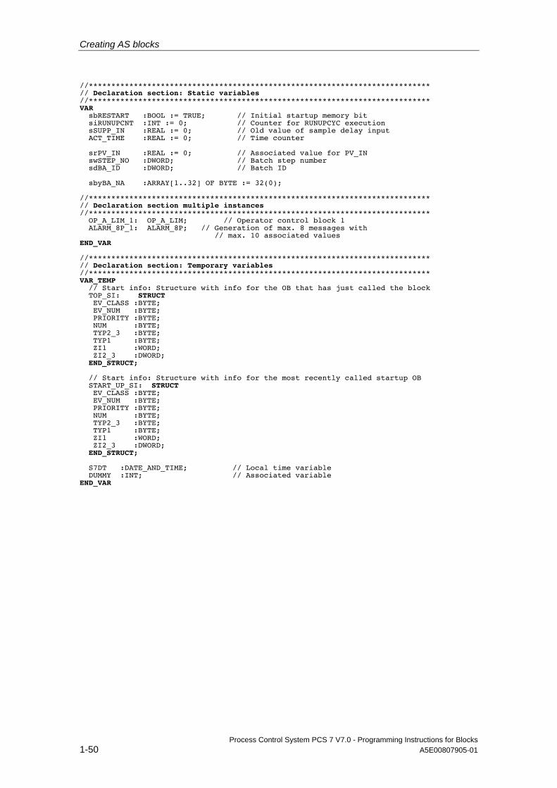
Creating AS blocks
Process Control System PCS 7 V7.0 - Programming Instructions for Blocks 1-50 A5E00807905-01
//**************************************************************************** // Declaration section: Static variables //**************************************************************************** VAR sbRESTART :BOOL := TRUE; // Initial startup memory bit siRUNUPCNT :INT := 0; // Counter for RUNUPCYC execution sSUPP_IN :REAL := 0; // Old value of sample delay input ACT_TIME :REAL := 0; // Time counter srPV_IN :REAL := 0; // Associated value for PV_IN swSTEP_NO :DWORD; // Batch step number sdBA_ID :DWORD; // Batch ID sbyBA_NA :ARRAY[1..32] OF BYTE := 32(0); //**************************************************************************** // Declaration section multiple instances //**************************************************************************** OP_A_LIM_1: OP_A_LIM; // Operator control block 1 ALARM_8P_1: ALARM_8P; // Generation of max. 8 messages with // max. 10 associated values END_VAR //**************************************************************************** // Declaration section: Temporary variables //**************************************************************************** VAR_TEMP // Start info: Structure with info for the OB that has just called the block TOP_SI: STRUCT EV_CLASS :BYTE; EV_NUM :BYTE; PRIORITY :BYTE; NUM :BYTE; TYP2_3 :BYTE; TYP1 :BYTE; ZI1 :WORD; ZI2_3 :DWORD; END_STRUCT; // Start info: Structure with info for the most recently called startup OB START_UP_SI: STRUCT EV_CLASS :BYTE; EV_NUM :BYTE; PRIORITY :BYTE; NUM :BYTE; TYP2_3 :BYTE; TYP1 :BYTE; ZI1 :WORD; ZI2_3 :DWORD; END_STRUCT; S7DT :DATE_AND_TIME; // Local time variable DUMMY :INT; // Associated variable END_VAR
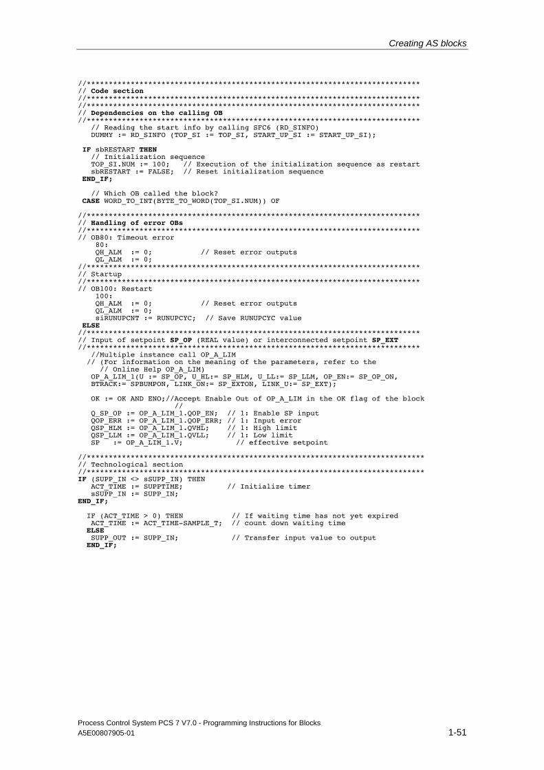
Creating AS blocks
Process Control System PCS 7 V7.0 - Programming Instructions for Blocks A5E00807905-01 1-51
//**************************************************************************** // Code section //**************************************************************************** //**************************************************************************** // Dependencies on the calling OB //**************************************************************************** // Reading the start info by calling SFC6 (RD_SINFO) DUMMY := RD_SINFO (TOP_SI := TOP_SI, START_UP_SI := START_UP_SI); IF sbRESTART THEN // Initialization sequence TOP_SI.NUM := 100; // Execution of the initialization sequence as restart sbRESTART := FALSE; // Reset initialization sequence END_IF; // Which OB called the block? CASE WORD_TO_INT(BYTE_TO_WORD(TOP_SI.NUM)) OF //**************************************************************************** // Handling of error OBs //**************************************************************************** // OB80: Timeout error 80: QH_ALM := 0; // Reset error outputs QL_ALM := 0; //**************************************************************************** // Startup //**************************************************************************** // OB100: Restart 100: QH_ALM := 0; // Reset error outputs QL_ALM := 0; siRUNUPCNT := RUNUPCYC; // Save RUNUPCYC value ELSE //**************************************************************************** // Input of setpoint SP_OP (REAL value) or interconnected setpoint SP_EXT //**************************************************************************** //Multiple instance call OP_A_LIM // (For information on the meaning of the parameters, refer to the // Online Help OP_A_LIM) OP_A_LIM_1(U := SP_OP, U_HL:= SP_HLM, U_LL:= SP_LLM, OP_EN:= SP_OP_ON, BTRACK:= SPBUMPON, LINK_ON:= SP_EXTON, LINK_U:= SP_EXT); OK := OK AND ENO;//Accept Enable Out of OP_A_LIM in the OK flag of the block // Q_SP_OP := OP_A_LIM_1.QOP_EN; // 1: Enable SP input QOP_ERR := OP_A_LIM_1.QOP_ERR; // 1: Input error QSP_HLM := OP_A_LIM_1.QVHL; // 1: High limit QSP_LLM := OP_A_LIM_1.QVLL; // 1: Low limit SP := OP_A_LIM_1.V; // effective setpoint //***************************************************************************** // Technological section //***************************************************************************** IF (SUPP_IN <> sSUPP_IN) THEN ACT_TIME := SUPPTIME; // Initialize timer sSUPP_IN := SUPP_IN; END_IF; IF (ACT_TIME > 0) THEN // If waiting time has not yet expired ACT_TIME := ACT_TIME-SAMPLE_T; // count down waiting time ELSE SUPP_OUT := SUPP_IN; // Transfer input value to output END_IF;
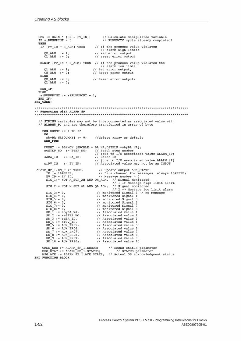
Creating AS blocks
Process Control System PCS 7 V7.0 - Programming Instructions for Blocks 1-52 A5E00807905-01
LMN := GAIN * (SP - PV_IN); // Calculate manipulated variable IF siRUNUPCNT = 0 // RUNUPCYC cycle already completed? THEN IF (PV_IN > H_ALM) THEN // If the process value violates // alarm high limits QH_ALM := 1; // set error output QL_ALM := 0; // reset error output ELSIF (PV_IN < L_ALM) THEN // If the process value violates the // alarm low limit QL_ALM := 1; // Set error output, QH_ALM := 0; // Reset error output ELSE QH_ALM := 0; // Reset error outputs QL_ALM := 0; END_IF; ELSE siRUNUPCNT := siRUNUPCNT - 1; END_IF; END_CASE; //***************************************************************************** // Reporting with ALARM_8P //***************************************************************************** // STRING variables may not be interconnected as associated value with // ALARM8_P, and are therefore transferred in array of byte FOR DUMMY := 1 TO 32 DO sbyBA_NA[DUMMY] := 0; //delete array as default END_FOR; DUMMY := BLKMOV (SRCBLK:= BA_NA,DSTBLK:=sbyBA_NA); swSTEP_NO := STEP_NO; // Batch step number // (due to I/O associated value ALARM_8P) sdBA_ID := BA_ID; // Batch ID // (due to I/O associated value ALARM_8P) srPV_IN := PV_IN; // Associated value may not be an INPUT ALARM_8P_1(EN_R := TRUE, // Update output ACK_STATE ID := 16#EEEE, // Data channel for messages (always 16#EEEE) EV_ID:= EV_ID, // Message number > 0 SIG_1:= NOT M_SUP_AH AND QH_ALM, // Signal monitored // 1 -> Message high limit alarm SIG_2:= NOT M_SUP_AL AND QL_ALM, // Signal monitored // 2 -> Message low limit alarm SIG_3:= 0, // monitored Signal 3 -> no message SIG_4:= 0, // monitored Signal 4 SIG_5:= 0, // monitored Signal 5 SIG_6:= 0, // monitored Signal 6 SIG_7:= 0, // monitored Signal 7 SIG_8:= 0, // monitored Signal 8 SD_1 := sbyBA_NA, // Associated value 1 SD_2 := swSTEP_NO, // Associated value 2 SD_3 := sdBA_ID, // Associated value 3 SD_4 := srPV_IN, // Associated value 4 SD_5 := AUX_PR05, // Associated value 5 SD_6 := AUX_PR06, // Associated value 6 SD_7 := AUX_PR07, // Associated value 7 SD_8 := AUX_PR08, // Associated value 8 SD_9 := AUX_PR09, // Associated value 9 SD_10:= AUX_PR10); // Associated value 10 QMSG_ERR := ALARM_8P_1.ERROR; // ERROR status parameter MSG_STAT := ALARM_8P_1.STATUS; // STATUS parameter MSG_ACK := ALARM_8P_1.ACK_STATE; // Actual OS acknowledgment status END_FUNCTION_BLOCK
Process Control System PCS 7 V7.0 - Programming Instructions for Blocks A5E00807905-01 2-1
2 Configuring faceplates
2.1 General notes re configuration
2.1.1 Requirements and previous experience
The next chapters provide all information users need to create a faceplate for PCS 7. This comprises information about using the corresponding WinCC tools and in particular about working with Faceplate Designer.
Note
The block icons and faceplates included in this description represent examples which may deviate in certain details from actual objects visualized.
Requirements and previous experience The faceplates described in this documentation are designed for applications in WinCC. You need the WinCC basic package which contains the process control options "Basic Process Control" and "Advanced Process Control" in order to create faceplates.
Knowledge requirements:
• SIMATIC WinCC System Course
• SIMATIC WinCC Openness N
These courses are offered at the A&D Training Center.
Configuring faceplates
Process Control System PCS 7 V7.0 - Programming Instructions for Blocks 2-2 A5E00807905-01
2.1.2 Creation phases
2.1.2.1 Roadmap to creation
The steps outlined below show the best practice in creating faceplates:
• Design of the faceplate
• Configuring the faceplate
• Test of the faceplate
2.1.2.2 Design of the faceplate
Representation A faceplate represents the O&M interface to an AS block. There are two options of visualizing a faceplate:
• Group display: Visualization of AS values in different views, with element for selecting the loop display
• Loop display: Visualization of the elements of all views of the group display
System attributes You define which particular input, output and in/out parameters of an AS block can be controlled and monitored by configuring the system attributes when you create the AS block. For detailed information about these system attributes, refer to the chapter "AS block structure".
Parameters Parameter selection criteria:
• Specific data the operators require to quickly and definitely register actual states
• How to visualize these values
• Particular values which can be edited by operators
• User access rights
• Process-dependent interlocks of operator input
• Specific faceplate views for the visualization of values
Tip: Group the parameters based on functions. Insert essential elements and in particular dynamic elements into the "Standard" view.
Configuring faceplates
Process Control System PCS 7 V7.0 - Programming Instructions for Blocks A5E00807905-01 2-3
Design After having defined the parameters and their visualization, continue with the faceplate design:
• Select the faceplate elements
• Name the faceplate elements
• Program the faceplate elements
• Position the faceplate elements
Use pronounceable names which relate to the objects to be visualized.
Example Assign the name "OCCUPIED" to the status view which is used to visualize the "OCCUPIED" variable. This procedure facilitates project documentation and maintenance.
2.1.2.3 Configuring the faceplate
WinCC Graphics Designer Use the "WinCC Graphics Designer" tool of your SW package to configure the faceplates. Using the templates of Faceplate Designer, implement the WinCC pictures based on your faceplate design. For detailed information, refer to chapter 2.1.3, "Creating faceplates using Faceplate Designer".
Configuring faceplates
Process Control System PCS 7 V7.0 - Programming Instructions for Blocks 2-4 A5E00807905-01
2.1.2.4 How to test a faceplate
Procedure To test the faceplate:
1. In WinCC Explorer, check the properties of the pictures you created based on the following criteria:
- Correct spelling of the parameter names
- Parameters visualized at multiple instances are assigned the same WinCC cycle Different cycles are liable to cause confusion among operating personnel, for example, due to inconsistency developing between the bar graph and numerical displays, and also increase communication load on the system
- Correct direct connections
- All event-controlled scripts are available
2. In WinCC Runtime, check the properties of the pictures created based on the criteria listed below:
- The faceplate opens in the group display when the user clicks the block icon
- The views can be toggled appropriately in the group display
- The faceplate opens in the loop display when the user clicks the "Loop display" button
- The correct values of the AS block are returned
- Correct visualization of the message and trend view
- Proper functioning of the input enable function for controlling parameters
- Values input by the operator are written to the AS block
- Faultless operating log
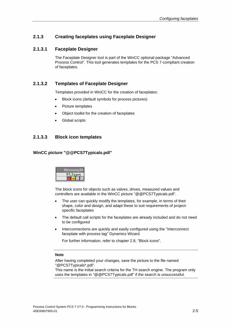
Configuring faceplates
Process Control System PCS 7 V7.0 - Programming Instructions for Blocks A5E00807905-01 2-5
2.1.3 Creating faceplates using Faceplate Designer
2.1.3.1 Faceplate Designer
The Faceplate Designer tool is part of the WinCC optional package "Advanced Process Control". This tool generates templates for the PCS 7-compliant creation of faceplates.
2.1.3.2 Templates of Faceplate Designer
Templates provided in WinCC for the creation of faceplates:
• Block icons (default symbols for process pictures)
• Picture templates
• Object toolkit for the creation of faceplates
• Global scripts
2.1.3.3 Block icon templates
WinCC picture "@@PCS7Typicals.pdl"
The block icons for objects such as valves, drives, measured values and controllers are available in the WinCC picture "@@PCS7Typicals.pdl".
• The user can quickly modify the templates, for example, in terms of their shape, color and design, and adapt these to suit requirements of project-specific faceplates
• The default call scripts for the faceplates are already included and do not need to be configured
• Interconnections are quickly and easily configured using the "Interconnect faceplate with process tag" Dynamics Wizard
For further information, refer to chapter 2.8, "Block icons".
Note
After having completed your changes, save the picture to the file named "@PCS7Typicals*.pdl". This name is the initial search criteria for the TH search engine. The program only uses the templates in "@@PCS7Typicals.pdl" if the search is unsuccessful.
Configuring faceplates
Process Control System PCS 7 V7.0 - Programming Instructions for Blocks 2-6 A5E00807905-01
2.1.3.4 Picture templates
Pictures and bitmaps The pictures and bitmaps are copied from the "WinCC\options\pdl\FaceplateDesigner_V6" folder and to the project using OS Project Editor. Refer to "OS Project Editor basic data" in the online help system.
Object toolkit The WinCC picture "@PCS7Elements.pdl" contains a number of object templates, i.e. user objects such as IO fields and texts, which can be used to create a faceplate. The picture is available in "Siemens\WinCC\options\pdl\FaceplateDesigner_V6" and is copied from there to the "GraCS" subfolder of the project folder when you run the OS Project Editor session.
For further information, refer to chapter 2.3, "Basic elements".
Global scripts Runtime functions or faceplate calls are available as global scripts in the "WinCC\aplib\FaceplateDesigner_V6" folder.
For further information, refer to chapter 2.4, "Scripts".

Configuring faceplates
Process Control System PCS 7 V7.0 - Programming Instructions for Blocks A5E00807905-01 2-7
2.1.3.5 Configuring sequence
Notes re configuration To observe when configuring faceplates:
• The faceplates created in Faceplate Designer are initially saved to the "GraCS" folder of your currently active project User-specific faceplates can be saved to the "\Siemens\WINCC\options\pdl\FaceplateDesigner" folder and are there available to all other projects
In OS Project Editor, you can select the default faceplates to copy from "\Siemens\WINCC\options\pdl\FaceplateDesigner_V6", and the user-specific faceplates to copy from "\Siemens\WINCC\options\pdl\FaceplateDesigner" to the project when generating the basic data
• Also copy the data from "\Siemens\WINCC\options\pdl\FaceplateDesigner" to the corresponding folder which contains the WinCC clients
Using the "Global Script" editor you can read/write protect functions configured for user-specific faceplates. For further information, refer to "Global Script" editor documentation.
• The dynamic functions of faceplates created in Faceplate Designer can be controlled by means of configuration data In particular the performance of a faceplate is determined by the selection of a suitable dynamics configuration An important aspect is an optimized, lean interface between the AS and OS function This especially applies to the block icons
Note
It is advisable in this context to implement the new status word "VSTATUS" introduced in V6 for integration in the AS blocks in particular for block icons in order to cut down on variable interconnections. The new status word could not be used in this case, as the default symbols must be compatible with V5 in order to be able to visualize AS blocks of this version.
• The type-specific dynamic functions of the faceplates may not be controlled using C-syntax scripts which contain fixed coding of instance names
Configuring faceplates
Process Control System PCS 7 V7.0 - Programming Instructions for Blocks 2-8 A5E00807905-01
2.1.4 Access control
2.1.4.1 Assigning user rights
Assigning instance-specific user rights The system supports the assignment of instance-specific user rights at the faceplates.
The configuration and instance-specific data are saved to the block icon files.
The block icon features the "Processcontrolling_backup" and "HigherProcesscontrolling_backup" properties at which you can configure user rights for process control and for higher-priority process control.
The information is transferred to the faceplate by means of script.
The default access levels 5 and 6 set at the properties can be changed as required. However, you should note that levels 1 to 10 are assigned permanent definitions in WinCC.
The assignment of one of these access levels to specific parameters is derived from the previous faceplates. Process control operations such as "On", "Off", "Manual", "Auto", "Set setpoint" are assigned access level 5, whereas higher-priority parameters such as "Limits" or "Control parameters" are assigned access level 6.
Area-specific user rights Area-specific user rights are retained as usual.
Area-specific user rights are verified on the basis of the assigned variable name, (tag name). However, it is necessary in this context to configure the corresponding area name at the "OS area" parameter of the TH, and that this setting matches the actual OS area in the Picture Tree.

Configuring faceplates
Process Control System PCS 7 V7.0 - Programming Instructions for Blocks A5E00807905-01 2-9
2.1.4.2 Configuring user rights for basic elements
Objects "@Level5" and "@Level6" The "@Level5" and "@Level6" objects of the views generated by Faceplate Designer can be used to configure user rights.
New basic elements of a view can be directly interconnected with the "@Level5" und "@Level6" objects.
You may not delete these objects, as they receive data from the scripts.
The "Background color" and "Control enable" properties are logically linked in order to gray out the field if a user is not authorized.
In order to enable user login to objects for AS parameters, the password level can also be interconnected by means of direct connection. Instead of graying out the objects when user login is not authorized, the program outputs a "No permission" message box.
A more practical means of combining WinCC and process-specific permissions in a control element of the basic elements is provided by the "Permission" object. The object properties are described in this element.
The values of these properties are controlled by the "PCS7_UpdatePermission_V6" script.
Access level 5 is set at "@Level5", and access level 6 is set at "@Level6" by default. The values returned at the block icon using the "Processcontrolling_backup" and "HigherProcesscontrolling_backup" properties can be modified for specific instances.
Procedure 1. Select the object, for example @Level6, for the access rights level required,
and then select "Object properties".
2. On the "Event Property topics Colors Background color", select a direct connection as action
3. Select the new object from the "Target" field on the right pane and the "Object in picture" field to select the background color as property
4. On the "Event Property topics Other Operator control enable" tab, select a direct connection as action A script which is already available for this event simultaneously controls the background color if the enable signal for user input is controlled by an AS variable In this case, you must delete the script
5. Select the new object from the "Target" field on the right pane and the "Object in picture" field to set the enable operator input property
Configuring faceplates
Process Control System PCS 7 V7.0 - Programming Instructions for Blocks 2-10 A5E00807905-01
When installing additional objects in a view, select the object most recently interconnected by means of direct connection, and then repeat the operations described earlier. Important! The configuration of the "Background color" and "Operator input enable" must match the configuration at "@Level5" and "@Level6". Example: background color = "gray", and operator input enable = "false". This ensures proper functioning of the scripts. Background information: If the script is used to set a value at the property and this value already exists in the configuration of this property, the value is not transferred to other properties by means of the direct connection. You should therefore make sure that the configured values of target properties which receive data at the direct connection match the values of the source properties.
2.1.5 Changing the overview
Creating a faceplate without messages and / or without group display When creating such a faceplate, you should delete certain elements and scripts from the "@PG_XXXXX_Overview.Pdl" in order to enhance performance. Elements and scripts to remove:
• Button16, message acknowledgment
• Button17, disable/enable messages
• @Level5, access rights
• MSG_LOCK, symbol for message suppression
• In the actual picture object, the script of the "Picture selection" event
• Also delete the batch symbol "OCCUPIED“ if the "Occupied" batch parameter does not exist
You can also enhance performance by activating the "no group display" and "no batch parameters" check boxes in Faceplate Designer.

Configuring faceplates
Process Control System PCS 7 V7.0 - Programming Instructions for Blocks A5E00807905-01 2-11
2.1.6 Configuring multiple instances
Multiple instance The term “multiple instance” denotes the existence of several blocks which are configured in a CFC chart and can be controlled and monitored at a faceplate on the OS.
Configuration The symbol is always interconnected in your configuration data with a complete variable name.
The check of user rights always encompasses the variable name selected and the entire faceplate.
Set the property MULTI_INSTANCE = 'true' at the "@Faceplate" object in the "@PG_xxxxx.pdl" and "@PL_xxxxx.pdl" pictures so that the program is able to detect the "Multiple instance" type and truncate the block name from the variable name after user rights were confirmed.
Append the /blockname string to all variable interconnections in the faceplate.
Example: /Controller.PV_IN.
Important: This action also has to be executed in the scripts!
Add these supplements to all interconnections of the OVERVIEW picture.
Define the properties of the batch parameters for the operating log of a block at the "@Faceplate" object in the "@PG_xxxxx.pdl" and "@PL_xxxxx.pdl" pictures. Multiple instance technology is ignored in this case. Special use cases such as different BatchIDs or StepNos. for different blocks are covered by script control when you select pictures in the various views.
The multiple instance technology is ignored in the trend view when "Mode = 2" is set.
Visualization of online trends is only available for the variable name stored at the block icon. You can set other modes in order to view the trends of several blocks.

Configuring faceplates
Process Control System PCS 7 V7.0 - Programming Instructions for Blocks 2-12 A5E00807905-01
Integrating several blocks with message functionality In order to integrate several blocks with message functionality, the following items must also be observed and implemented in the OVERVIEW picture:
• A sufficient number of group displays must be installed to match the number of message blocks installed
• Enhance the script with a function for controlling the message acknowledgment button Script "Button16/Mouseclick". The "CSigAPIAcknowledgeTagAndCreateLTM" function must be executed at each instance when you acknowledge a message
Example:
TCHAR sztag1[_MAX_PATH + 1] = "";
TCHAR sztag2[_MAX_PATH + 1] = "";
GetComputerNameA(szStation, &dwSize);
pszParentPicture = GetParentPicture(lpszPictureName);
lpszCurrentUser = GetPropChar(pszParentPicture ,"@Faceplate","CurrentUser");
pszTagname = GetPropChar(pszParentPicture ,"OverviewWindow","TagPrefix");
strcpy(sztag1,pszTagname);
strcpy(sztag2,pszTagname);
strcat(sztag1,"/Instanz1");
strcat(sztag2,"/Instanz2");
printf ("sztag2 : %s\r\n", sztag2);
if (!CSigAPIAcknowledgeTagAndCreateLTM(sztag1, lpszCurrentUser , szStation, &Err))
printf ("Error at CSigAPIAcknowledgePicture : %s\r\n", Err.szErrorText);
if (!CSigAPIAcknowledgeTagAndCreateLTM(sztag2, lpszCurrentUser , szStation, &Err))
printf ("Error at CSigAPIAcknowledgePicture : %s\r\n", Err.szErrorText);
Configuring faceplates
Process Control System PCS 7 V7.0 - Programming Instructions for Blocks A5E00807905-01 2-13
• Enhance the script with a function for controlling the "Disable/enable messages" button Script "Button17/Mouseclick". The "CSigAPILockMessage" function must be executed at each instance when the "Disable/enable messages" button is activated
Example:
DWORD dEventState1 = GetPropWord(lpszPictureName,"EventState","CollectValue");
DWORD dEventState2 = GetPropWord(lpszPictureName,"EventState2","CollectValue");
TCHAR sztag1[_MAX_PATH + 1] = "";
TCHAR sztag2[_MAX_PATH + 1] = "";
pszParentPicture = GetParentPicture(lpszPictureName);
pszTagname = GetPropChar(pszParentPicture ,"OverviewWindow","TagPrefix");
lpszCurrentUser = GetPropChar(pszParentPicture ,"@Faceplate","CurrentUser");
GetComputerNameA(szStation, &dwSize);
strcpy(sztag1,pszTagname);
strcpy(sztag2,pszTagname);
strcat(sztag1,"/R");
strcat(sztag2,"/M");
if ((dEventState & 65536) == 65536)
{
bRet = CSigAPILockMessage(FALSE, sztag1, lpszCurrentUser , szStation, &Err);
SetPictureUp(lpszPictureName,lpszObjectName,"@Lock.bmp");
}
else
{
bRet = CSigAPILockMessage(TRUE, sztag1, lpszCurrentUser , szStation, &Err);
SetPictureUp(lpszPictureName,lpszObjectName,"@Unlock.bmp");
}
if ((dEventState2 & 65536) == 65536)
{
bRet = CSigAPILockMessage(FALSE, sztag2, lpszCurrentUser , szStation, &Err);
Configuring faceplates
Process Control System PCS 7 V7.0 - Programming Instructions for Blocks 2-14 A5E00807905-01
SetPictureUp(lpszPictureName,lpszObjectName,"@Lock.bmp");
}
else
{
bRet = CSigAPILockMessage(TRUE, sztag2, lpszCurrentUser , szStation, &Err);
SetPictureUp(lpszPictureName,lpszObjectName,"@Unlock.bmp");
}
• Install a message suppression symbol (MSG_LOCK) for all blocks with message functionality
• Integrate an OCCUPIED symbol for all batch-relevant blocks
Configuring faceplates
Process Control System PCS 7 V7.0 - Programming Instructions for Blocks A5E00807905-01 2-15
2.1.7 Configuring number formats
New properties for number formatting The relevant block icons are assigned three new number formatting properties:
Format_InputValue For input values such as "Setpoint" and "ProcessValue" at the
block icon Format_OutputValue For the manipulated variable at the block icon Format_xx For any other values
Note
The terms "Format_InputValue" and "Format_OutputValue" selected in this context are process-oriented and are not directly relevant to the I/O of the AS block parameters.
Example: The FMT_PID parameter "PV" represents an output parameter at the AS block, however, in terms of the process it represents an input variable.
Format_InputValue and Format_OutputValue are used to format the analog values of the block icon.
With default setting, Format_InputValue returns floating decimals and two floating decimal places. It always returns at least one decimal (0.##).
With default setting, Format_OutputValue returns floating decimals and two floating decimal places. It always returns at least one decimal (0.##).
The project engineer can adapt these default settings to suit a specific instance.
All three format properties of the block icon are transferred to the faceplate by script, and can there be assigned to the analog values via direct connection.
Details: The format properties of the block icon are transferred and saved to the “Format” object of the parent prototype picture "@PG_xxxxx.pdl" using the "PCS7_OpenGroupDisplay_V6" script.
If a view contains a "Format" object that is assigned the "Format_InputValue, Format_OutputValue, Format_xx" properties, these formats are transferred directly to this object using the "PCS7_Format_V6" script when a picture is selected.
From this object you can assign these three formats to any analog value in this view by creating a direct connection.
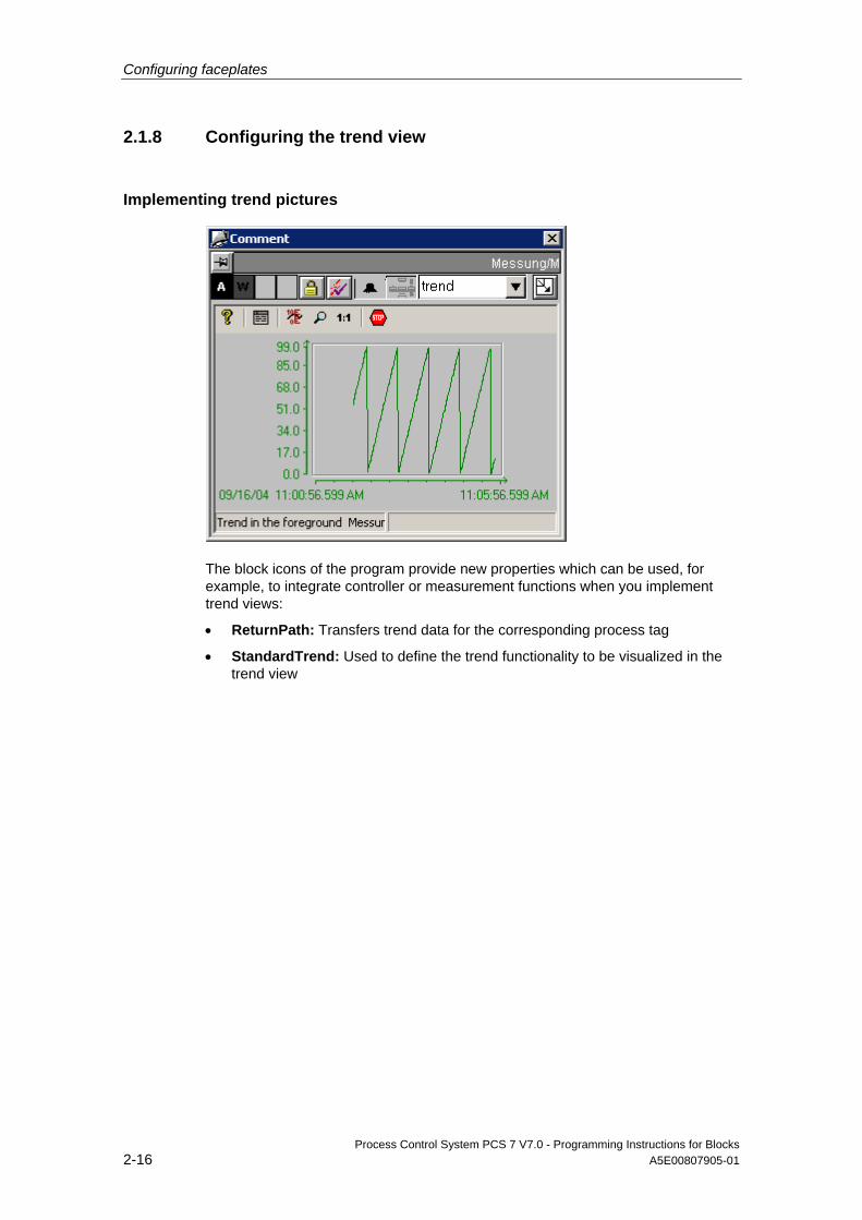
Configuring faceplates
Process Control System PCS 7 V7.0 - Programming Instructions for Blocks 2-16 A5E00807905-01
2.1.8 Configuring the trend view
Implementing trend pictures
The block icons of the program provide new properties which can be used, for example, to integrate controller or measurement functions when you implement trend views:
• ReturnPath: Transfers trend data for the corresponding process tag
• StandardTrend: Used to define the trend functionality to be visualized in the trend view
Configuring faceplates
Process Control System PCS 7 V7.0 - Programming Instructions for Blocks A5E00807905-01 2-17
Default trend:
Mode
0 Trend functionality similar to V5, i.e. a separate trend picture must be configured for each instance. The trend view "@PCS7_TREND.pdl" is available for all PCS7 faceplates and contains the "TrendPicture" window. To visualize the trend view of a process tag on this area: 1st Open WinCC Editor "Tag Logging". 2nd Create a variable archive for the trend view using the Archive Wizard. 3rd Create the variables for this archive. For detailed information about the steps mentioned earlier, refer to the WinCC Online Help, index "Tag Logging". 4th Open the "@CONL1_Standard.pdl" picture in Graphics Designer. 5th Configure the TlgOnlineTrend object "Control1" to suit requirements. Click "Help" for
further information. 6th Save the picture to a file named "@CONL1_<tagname>.pdl". The variable name <tagname> must match the name of the process tag of the AS block. Replace the "/" with the "_" character in the name, because Windows does not support the "/" character in file names. Example of the window name of a process tag with the variable name "Measurement/M“ @CONL1_Messung_M.pdl
2 A "@CONL1_Standard.pdl" picture is called where you enter one or several online variables. An archive is not required. x axis = 5 min This is the default setting as you neither have to make provisions in configuration data nor have to comply with naming conventions in terms of the visualization of trends. The ReturnPath property in the block icon returns the number of trends, the name of the structure element and the color.
>2 A "@CONL1_Standard.pdl” picture is called where you enter one or several online archive variable names. You must comply with conventions outlined below in order to ensure proper functioning of this configuration without having to program further functions: • The archive must be named "Prozesswertarchiv", regardless of the language setting. • The archive and the variable must be available on the same server. • The archive variable name must comply with the default name you assign when creating
the archive variable. • If the server prefix is included in the variable name of the "tagname" property of the block
icon, the server prefix must be set without "::" in the archive variable name. • If the variable name entered in the "tagname" property does not contain a server prefix,
the archive variable name must match the variable name. Note: The archive variable name is represented in previous versions by the "tagname" without "/" separators. In V6 or higher, the archive variable name corresponds with the "tagname". The archive variable must be assigned this name in order to ensure proper functioning of the trend in the faceplate. The ReturnPath property in the block icon is used to return the number of trends, the variable name and the color. in this mode, the duration of the axis x cycle (in minute units) is read from parameter "StandardTrend".

Configuring faceplates
Process Control System PCS 7 V7.0 - Programming Instructions for Blocks 2-18 A5E00807905-01
Default trend:
Mode
ReturnPath syntax: .PV_IN : CO_GREEN ,
Structure element name with dot for the initial trend Separator between the structure element name and the color Color of the first trend Comma for a further trend
Example: .PV_IN:CO_DKGREEN,.SP:CO_BLUE,.LMNR_IN:CO_DKRED (default setting for CTRL_PID) The example shows three controller trends, that is, the actual value, setpoint and manipulated value feedback. If you cannot adhere to the four conventions mentioned earlier, you can expand the "ReturnPath“ property by assigning additional parameters: *tagname: individual archive variable name *archivname: individual archive name (entered without „\") *archivserver: The trend is available on an archive server. Enter the server prefix of the archive server without "::" characters Example: .PV_IN:CO_DKGREEN,.SP:CO_BLUE,.LMNR_IN:CO_DKRED*tagname: MySpecialTag*archivname:MySpecialArchivname*archivserver: MySpecialArchivServer Note: You can only define a "tagname", "archivname" or the "archivserver" at the end of the strings. Adapt the archive variable names accordingly when using multiple instances. The archive variable may only differ in term of member variables. Example of a multiple instance: The CFC chart "MULTI" contains the MEAS_MON blocks "M1" and "M2". The program generates the default names "MULTI/M1.U" and "MULTI/M2.U" as archive variable names for process value "U".
*asia: add server prefix to archive tag If parameter *asia: is not used, any existing server prefix in "tagname" is also included in the derivative of the archive tag name. If "tagname" does not contain a server prefix the program does not make allowances for a server prefix in the derivative of the archive tag name. *asia:MyServerPrefix The archive tag name contains a server prefix without "::" and the "tagname" property of the block icon does not contain this prefix. In this case you can supplement the server prefix (enter without "::"). *asia: The archive tag name does not contain a server prefix. In this case you can hide the server prefix. This variant should also be used if the "tagname" property at the server does not contain a server prefix entry, as the server prefix is always available when the client calls the picture.
Configuring faceplates
Process Control System PCS 7 V7.0 - Programming Instructions for Blocks A5E00807905-01 2-19
Default trend:
Mode
Rename the archive tags to "MULTI.M1_U“ and "MULTI.M2_U“ Text string in the ReturnPath of the block icon: .M1_U:CO_DKGREEN,.M2_U:CO_BLUE*tagname:MULTI*archivname:SystemArchive Example of *asia: Show server prefix: .U:CO_DKGREEN*asia:OS(1)_PC2 Example of *asia: Hide server prefix .U:CO_DKGREEN*asia:
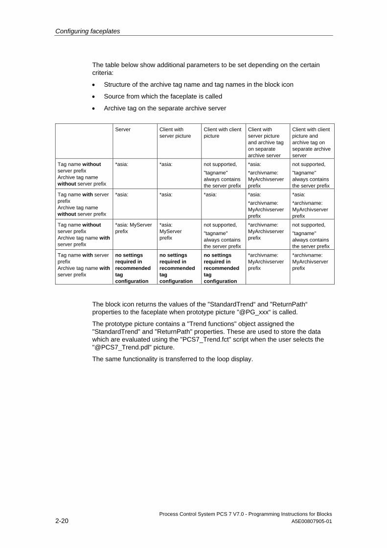
Configuring faceplates
Process Control System PCS 7 V7.0 - Programming Instructions for Blocks 2-20 A5E00807905-01
The table below show additional parameters to be set depending on the certain criteria:
• Structure of the archive tag name and tag names in the block icon
• Source from which the faceplate is called
• Archive tag on the separate archive server
Server Client with
server picture Client with client picture
Client with server picture and archive tag on separate archive server
Client with client picture and archive tag on separate archive server
Tag name without server prefix Archive tag name without server prefix
*asia: *asia: not supported, "tagname" always contains the server prefix
*asia: *archivname: MyArchivserver prefix
not supported, "tagname" always contains the server prefix
Tag name with server prefix Archive tag name without server prefix
*asia: *asia: *asia: *asia: *archivname: MyArchivserver prefix
*asia: *archivname: MyArchivserver prefix
Tag name without server prefix Archive tag name with server prefix
*asia: MyServer prefix
*asia: MyServer prefix
not supported, "tagname" always contains the server prefix
*archivname: MyArchivserver prefix
not supported, "tagname" always contains the server prefix
Tag name with server prefix Archive tag name with server prefix
no settings required in recommended tag configuration
no settings required in recommended tag configuration
no settings required in recommended tag configuration
*archivname: MyArchivserver prefix
*archivname: MyArchivserver prefix
The block icon returns the values of the "StandardTrend“ and "ReturnPath“ properties to the faceplate when prototype picture "@PG_xxx“ is called.
The prototype picture contains a "Trend functions" object assigned the "StandardTrend" and "ReturnPath" properties. These are used to store the data which are evaluated using the "PCS7_Trend.fct" script when the user selects the "@PCS7_Trend.pdl" picture.
The same functionality is transferred to the loop display.
Configuring faceplates
Process Control System PCS 7 V7.0 - Programming Instructions for Blocks A5E00807905-01 2-21
2.1.9 How to configure an AS block type with different block icons and faceplate types
Procedure You only need to change the "type" property at the block icon to generate a symbol variant for the AS block.
Any faceplate variant you may want to generate for an AS block must be assigned a name other than that of the AS block type. Example: variation of "MEAS_MON" is the faceplate name "MEAS_NEW".
Settings to make at the block icon:
1. Rename the "Servername" property to "PCS7 MEAS_NEU Control".
2. Create a new "StructureType" property at the block icon which contains the AS block type ("MEAS_MON") This is necessary to ensure that the "Link faceplate to process tag“ wizard is still able to select the variable
Configuring faceplates
Process Control System PCS 7 V7.0 - Programming Instructions for Blocks 2-22 A5E00807905-01
2.1.10 WebClient (differences compared to WinCC)
2.1.10.1 Differences in terms of faceplate configuration
The next section shows which differences between WinCC
and WebClient should be taken into consideration.
2.1.10.2 Picture names
Addressing WinCC scripts deploy absolute or relative addressing of picture names.
Example:
• absolute
@screen.@win12:@1001.@top09:@pg_elap_cnt.OverviewWindow:@PG_ELAP_CNT_OverView.pdl
• relative
@PG_ELAP_CNT_OverView.pdl
The WebClient only supports relative addressing within the script context.
Also, you should define the picture window name instead of the picture name as address when using WebClient scripting.
Example:
SetPropChar(lpszPictureName,lpszObjectName,lpszPropertyName,szValue);
WinCC: the lpszPictureName is a pointer to the picture name
WebClient: lpszPictureName is a pointer to the picture window name
Exceptions are the picture to which the script belongs and the parent picture (ParentPicture), i.e. the picture name can be used as pointer. It is advisable always to use the picture window name as the pointer to this name is unambiguous. The picture name may be ambiguous.
Example of relative picture addressing:
The @PG_xxx.pdl picture contains a "View" window which is used, for example, to visualize the default view of a faceplate. When addressing a different window of the @PG_xxx.pdl picture in the screen which returns the default view in the "View" window, the relative window address is determined as shown below:
sprintf(szPictureName,"../OperationWindow");
Configuring faceplates
Process Control System PCS 7 V7.0 - Programming Instructions for Blocks A5E00807905-01 2-23
2.1.10.3 Case-sensitivity in file names
File names, for example for pointers to picture names, are generally provided in WinCC as created, that is, in uppercase format. Example: @PG_MEAS_MON.PDL.
On the Web client, the file names are supplied as created, for example, @Pg_Meas_Mon.pdl.
It may be necessary to adapt these names when comparing strings.
Example:
( strcmp( GetPictureUp(lpszPictureName,lpszObjectName), "@KEEPVISIBLEON.EMF") == 0 )
This adaptation is not subject to any limitation in WinCC. However the Web function supports this adaptation only for file names consisting of uppercase letters.
Adaptation required: ( strcmp( _strlwr(GetPictureUp(lpszPictureName,lpszObjectName)), "@keepvisibleon.emf") == 0 )
2.1.10.4 Loading pictures in picture windows
Differences in WinCC compared to WebClient in terms of the loading pictures in the windows:
• WinCC After having loaded a picture to a window in WinCC, for example, using the SetVisible function, you can directly address and edit their objects by calling the scripting function.
• WebClient Pictures are loaded on the WebClient in asynchronous mode. You need to implement a delay in the scripts for this reason in order to delay further execution of the script if this is also used to address picture objects The WebClient is provided the corresponding WaitForDocumentReady("Window name"); function This function delays script execution until the window name parameter reports a loaded picture
Configuring faceplates
Process Control System PCS 7 V7.0 - Programming Instructions for Blocks 2-24 A5E00807905-01
2.1.10.5 Deselecting pictures within scripts Differences in WinCC compared to WebClient in terms of deselecting pictures within scripts: • WinCC
WinCC supports the "Set invisible" picture function in scripts executed within the context of this picture, that is, the function can be executed at any section of the script, as the script execution task continues scripting independent of the closed picture.
• WebClient On the WebClient, the "Set invisible" function must be the last action executed in the script All script instructions following "set invisible“ are no longer executed as the script terminates at this point
2.1.10.6 Distinguishing between the WinCC <-> Web runtime environments It is necessary to be able to distinguish between the WinCC and WebClient runtime environments when running scripts for graphical picture objects or project functions. The program provides the corresponding compiler instructions: • #ifdef RUN_ON_WEBNAVIGATOR • #ifndef RUN_ON_WEBNAVIGATOR (= negation) These instructions can be used, for example, to make allowances for the differences between WinCC and WebClient as shown below: • Script delay using WaitForDocumentReady • Different picture addressing • Different function names for process control functions • Functions not to be supported in WebClient
Example of the PCS7_ChangeView script #ifdef RUN_ON_WEBNAVIGATOR
SetPropChar("../", "View", "PictureName", szViewName);
WaitForDocumentReady("../View");
#else
SetPropChar(lpszParent, "View", "PictureName", szViewName);
#endif
Note
Instead of checking the syntax of the Web code section when you compile the WinCC script, the program checks it only when you publish the pictures.
Configuring faceplates
Process Control System PCS 7 V7.0 - Programming Instructions for Blocks A5E00807905-01 2-25
2.1.10.7 Function names in WinCC/Web
List of supported functions The action-triggering functions were mapped to other function names for the Web in order to trigger the action in the Webnavigator Client instead of triggering it in WinCC Runtime.
Example:
SSMRTChangeWorkdfield modifies the working window in WinCC Runtime and
SSMChangeWorkdfield modifies the working window in the WebClient.
A list of supported functions and their names is available in the corresponding product descriptions. The "Faceplate Designer" product supports the following functionality:
void PCS7_ChangeView(char* lpszPictureName, char* lpszObjectName);
BOOL PCS7_CheckPermission(char* lpszTagname, DWORD dwLevel);
void PCS7_UpdateGroupPermission(char* lpszPictureName);
void PCS7_UpdateGroupTagname(char* lpszPictureName, char* lpszObjectName, char* value);
void PCS7_UpdateLoopTagname(char* lpszPictureName, char* lpszObjectName, char* value);
void PCS7_UpdatePermission_V6(char* lpszParentPictureName, int CallFrom, char* lpszPictureName);
void PCS7_OpenGroupDisplay_V6(char *lpszPictureName, char *lpszObjectName );
void PCS7_OpenLoopDisplay_V6(char* lpszPictureName);
void PCS7_OpenInputBoxBin_V6(char *lpszPictureName,char *lpszObjectName, int CallFrom);
void PCS7_1vnStati_Variable_Changed_V6(char* lpszPictureName, char* lpszObjectName, char* lpszPropertyName, double value);
void PCS7_OperationLog_V6(char* lpszPictureName, double dOldValue, double dNewValue, char* lpszOperationText, char* lpszUnit);
void PCS7_Trend_V6(char* lpszPictureName, char* lpszObjectName, char* lpszPropertyName, char * ArchivVar, char* OnlineVar, DWORD TrendColor, int CallFrom);
void PCS7_UpdateGroupTagname_V6(char* lpszPictureName, char* lpszObjectName, char* value);
void PCS7_UpdateLoopTagname_V6(char* lpszPictureName, char* lpszObjectName, char* lpszTagName);
void PCS7_UpdateBarLimits_V6(char* lpszPictureName, char* lpszObjectName, int CallFrom);
void PCS7_UpdateBar_V6(char* lpszPictureName, char* lpszObjectName, int CallFrom);
void PCS7_OpenInputBoxAnalog_V6(char *lpszPictureName,char *lpszObjectName,int CallFrom);

Configuring faceplates
Process Control System PCS 7 V7.0 - Programming Instructions for Blocks 2-26 A5E00807905-01
void PCS7_OpenGroupDisplay_I_V6(char *lpszPictureName, char *lpszObjectName, char*lpszInterlokName);
void PCS7_OpenComboBox_V6(char *lpszPictureName,char *lpszObjectName,int CallFrom);
void PCS7_OpenCheckBox_V6(char *lpszPictureName,char *lpszObjectName, int CallFrom);
void PCS7_Open3ComboBox_V6(char *lpszPictureName,char *lpszObjectName,int CallFrom);
void PCS7_Format_V6(char* lpszPictureName, char* lpszObjectName, int CallFrom,char* lpszParent);
void PCS7_Combo_OK_V6(char* lpszPictureName, char* lpszObjectName, char* lpszPropertyName);
void PCS7_Check_OK_V6(char* lpszPictureName, char* lpszObjectName, char* lpszPropertyName);
void PCS7_Binary_OK_V6(char* lpszPictureName, char* lpszObjectName, char* lpszPropertyName);
void PCS7_AnalogPercent_V6(char* lpszPictureName, char* lpszObjectName, char* lpszPropertyName,double Percent);
void PCS7_Analog_OK_V6(char* lpszPictureName, char* lpszObjectName, char* lpszPropertyName);
void PCS7_3Combo_OK_V6(char* lpszPictureName, char* lpszObjectName, char* lpszPropertyName);
void PCS7_2Stati_Variable_Changed_V6(char* lpszPictureName, char* lpszObjectName, char* lpszPropertyName, double value);
2.1.10.8 Global script
"Global Script" is not supported for the WebClient because it has no separate "Script.exe“ application.
Global functions must be saved as project functions. They are otherwise included in the compilation when you publish the data.
2.1.10.9 VBS Script
It is advisable to create new functions in VBS, as you do not have to make allowances in VBS for differences between WinCC and the WebClient.
2.1.10.10 Notes
By contrast to WinCC, scripts on the WebClient which are written in C do not provide global tags which can be shared by all pictures.
It is advisable to discard cyclic synchronous functions, as these generate longer runtimes on the WebClient compared to WinCC.
Configuring faceplates
Process Control System PCS 7 V7.0 - Programming Instructions for Blocks A5E00807905-01 2-27
2.1.11 Changing languages
The templates of Faceplate Designer are created in three languages: namely German, English and French. All texts are output in the relevant language set in WinCC. When installing additional text elements in a picture with optional language selection, these texts must be entered in Graphics Designer in all regional languages required. You change the language by selecting the View > Language... > Select language command in Graphics Designer
2.1.12 Texts for the input of analog and binary values from the ES
Setting the language The comment texts of binary and analog value displays, combo boxes, check boxes and operating logs are read from the parameter attributes of the block instances.
Note that all default texts in the ES for the "s7_shortcut", "s7_unit", "S7_string_0" and "S7_string_1" attributes are configured in English language.
In previous versions, the ES texts were only used for the operating log in the faceplates. In the faceplate views, the texts were previously created in WinCC and were made available in three regional languages.
Translate these ES texts into the language required when migrating to another version. Use the IEA if necessary.
Multilingual texts You can translate any texts for multilingual applications using the Text Library Editor in WinCC. In SIMATIC Manager, set the default dialog language, i.e. usually "English", for display devices which contain the control and display texts configured in STEP 7 and in the ES. This prevents overwriting of translated texts when you compile the OS.
Important information As the default texts are already available in English language in the ES, you should always create a project library for the AS blocks and translate their default English texts into the required language when you configure a project in a language other than English.
Make sure that the new texts do not exceed the length of the default texts. Verify that the texts are properly output to the faceplate if you cannot avoid longer texts.
For further information on the creation of project libraries, refer to the ES Configuration Manual.
You can ignore attribute "s7_unit" for translation, as space characters or internationally used short names were used in the default settings.
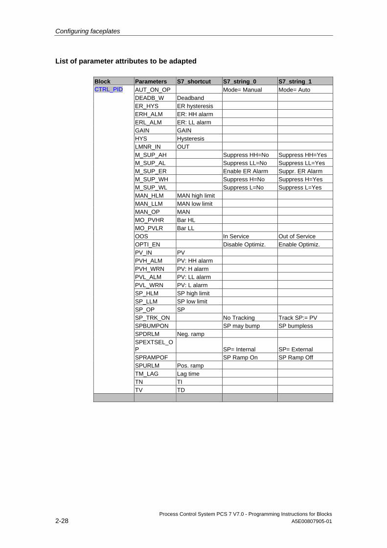
Configuring faceplates
Process Control System PCS 7 V7.0 - Programming Instructions for Blocks 2-28 A5E00807905-01
List of parameter attributes to be adapted Block Parameters S7_shortcut S7_string_0 S7_string_1
AUT_ON_OP Mode= Manual Mode= Auto DEADB_W Deadband ER_HYS ER hysteresis ERH_ALM ER: HH alarm ERL_ALM ER: LL alarm GAIN GAIN HYS Hysteresis LMNR_IN OUT M_SUP_AH Suppress HH=No Suppress HH=Yes M_SUP_AL Suppress LL=No Suppress LL=Yes M_SUP_ER Enable ER Alarm Suppr. ER Alarm M_SUP_WH Suppress H=No Suppress H=Yes M_SUP_WL Suppress L=No Suppress L=Yes MAN_HLM MAN high limit MAN_LLM MAN low limit MAN_OP MAN MO_PVHR Bar HL MO_PVLR Bar LL OOS In Service Out of Service OPTI_EN Disable Optimiz. Enable Optimiz. PV_IN PV PVH_ALM PV: HH alarm PVH_WRN PV: H alarm PVL_ALM PV: LL alarm PVL_WRN PV: L alarm SP_HLM SP high limit SP_LLM SP low limit SP_OP SP SP_TRK_ON No Tracking Track SP:= PV SPBUMPON SP may bump SP bumpless SPDRLM Neg. ramp SPEXTSEL_OP SP= Internal SP= External SPRAMPOF SP Ramp On SP Ramp Off SPURLM Pos. ramp TM_LAG Lag time TN TI
CTRL_PID
TV TD
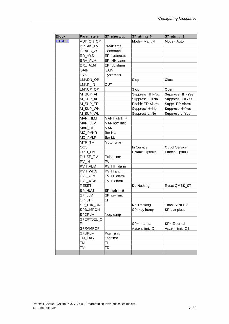
Configuring faceplates
Process Control System PCS 7 V7.0 - Programming Instructions for Blocks A5E00807905-01 2-29
Block Parameters S7_shortcut S7_string_0 S7_string_1 AUT_ON_OP Mode= Manual Mode= Auto BREAK_TM Break time DEADB_W Deadband ER_HYS ER hysteresis ERH_ALM ER: HH alarm ERL_ALM ER: LL alarm GAIN GAIN HYS Hysteresis LMNDN_OP Stop Close LMNR_IN OUT LMNUP_OP Stop Open M_SUP_AH Suppress HH=No Suppress HH=Yes M_SUP_AL Suppress LL=No Suppress LL=Yes M_SUP_ER Enable ER Alarm Suppr. ER Alarm M_SUP_WH Suppress H=No Suppress H=Yes M_SUP_WL Suppress L=No Suppress L=Yes MAN_HLM MAN high limit MAN_LLM MAN low limit MAN_OP MAN MO_PVHR Bar HL MO_PVLR Bar LL MTR_TM Motor time OOS In Service Out of Service OPTI_EN Disable Optimiz. Enable Optimiz. PULSE_TM Pulse time PV_IN PV PVH_ALM PV: HH alarm PVH_WRN PV: H alarm PVL_ALM PV: LL alarm PVL_WRN PV: L alarm RESET Do Nothing Reset QMSS_ST SP_HLM SP high limit SP_LLM SP low limit SP_OP SP SP_TRK_ON No Tracking Track SP:= PV SPBUMPON SP may bump SP bumpless SPDRLM Neg. ramp SPEXTSEL_OP SP= Internal SP= External SPRAMPOF Ascent limit=On Ascent limit=Off SPURLM Pos. ramp TM_LAG Lag time TN TI
CTRL_S
TV TD
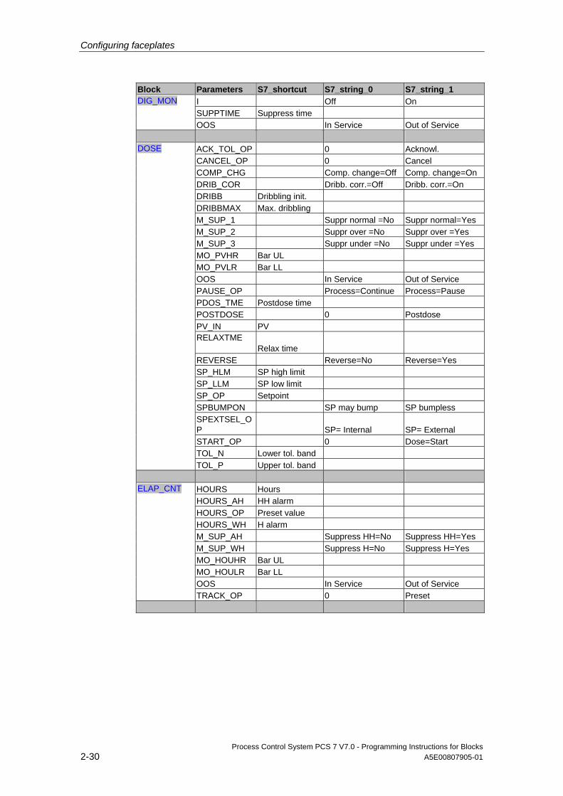
Configuring faceplates
Process Control System PCS 7 V7.0 - Programming Instructions for Blocks 2-30 A5E00807905-01
Block Parameters S7_shortcut S7_string_0 S7_string_1 I Off On SUPPTIME Suppress time
DIG_MON
OOS In Service Out of Service
ACK_TOL_OP 0 Acknowl. CANCEL_OP 0 Cancel COMP_CHG Comp. change=Off Comp. change=On DRIB_COR Dribb. corr.=Off Dribb. corr.=On DRIBB Dribbling init. DRIBBMAX Max. dribbling M_SUP_1 Suppr normal =No Suppr normal=Yes M_SUP_2 Suppr over =No Suppr over =Yes M_SUP_3 Suppr under =No Suppr under =Yes MO_PVHR Bar UL MO_PVLR Bar LL OOS In Service Out of Service PAUSE_OP Process=Continue Process=Pause PDOS_TME Postdose time POSTDOSE 0 Postdose PV_IN PV RELAXTME Relax time REVERSE Reverse=No Reverse=Yes SP_HLM SP high limit SP_LLM SP low limit SP_OP Setpoint SPBUMPON SP may bump SP bumpless SPEXTSEL_OP SP= Internal SP= External START_OP 0 Dose=Start TOL_N Lower tol. band
DOSE
TOL_P Upper tol. band
HOURS Hours HOURS_AH HH alarm HOURS_OP Preset value HOURS_WH H alarm M_SUP_AH Suppress HH=No Suppress HH=Yes M_SUP_WH Suppress H=No Suppress H=Yes MO_HOUHR Bar UL MO_HOULR Bar LL OOS In Service Out of Service
ELAP_CNT
TRACK_OP 0 Preset
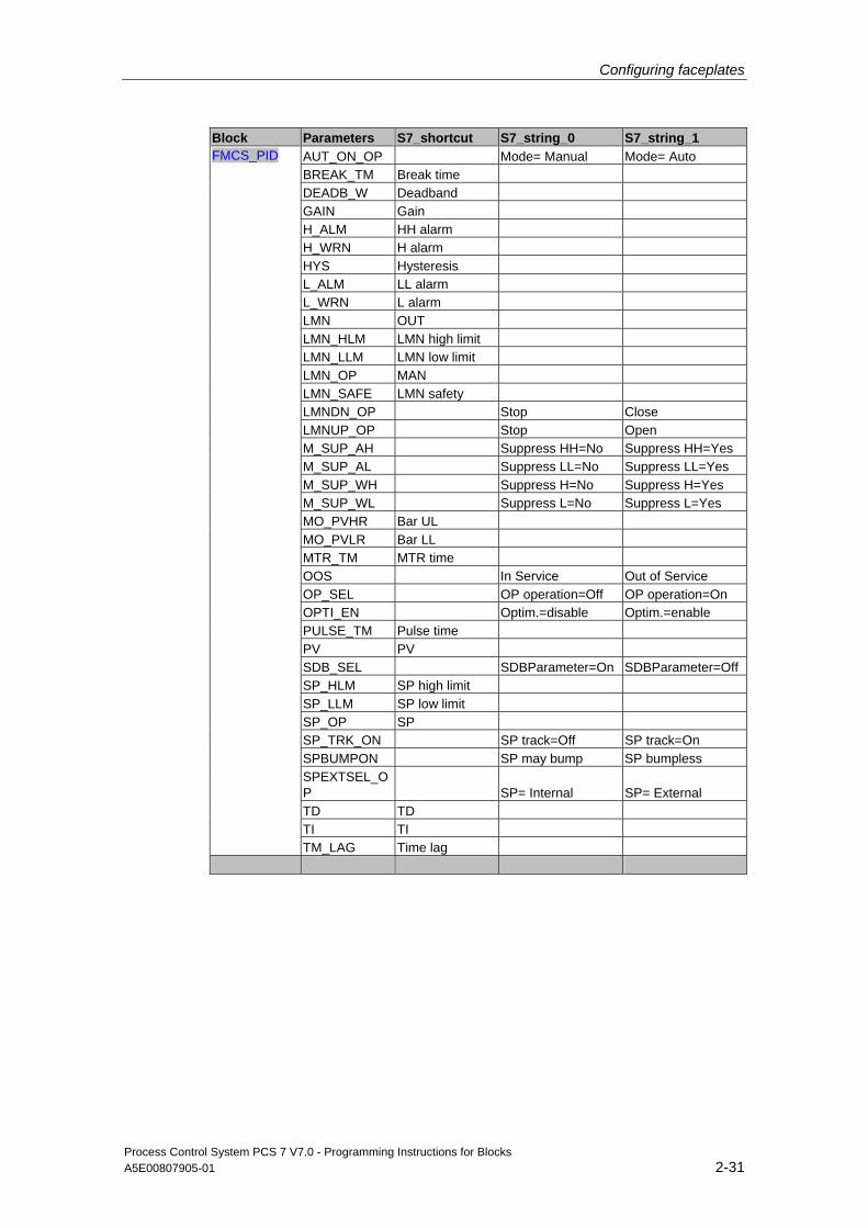
Configuring faceplates
Process Control System PCS 7 V7.0 - Programming Instructions for Blocks A5E00807905-01 2-31
Block Parameters S7_shortcut S7_string_0 S7_string_1 AUT_ON_OP Mode= Manual Mode= Auto BREAK_TM Break time DEADB_W Deadband GAIN Gain H_ALM HH alarm H_WRN H alarm HYS Hysteresis L_ALM LL alarm L_WRN L alarm LMN OUT LMN_HLM LMN high limit LMN_LLM LMN low limit LMN_OP MAN LMN_SAFE LMN safety LMNDN_OP Stop Close LMNUP_OP Stop Open M_SUP_AH Suppress HH=No Suppress HH=Yes M_SUP_AL Suppress LL=No Suppress LL=Yes M_SUP_WH Suppress H=No Suppress H=Yes M_SUP_WL Suppress L=No Suppress L=Yes MO_PVHR Bar UL MO_PVLR Bar LL MTR_TM MTR time OOS In Service Out of Service OP_SEL OP operation=Off OP operation=On OPTI_EN Optim.=disable Optim.=enable PULSE_TM Pulse time PV PV SDB_SEL SDBParameter=On SDBParameter=Off SP_HLM SP high limit SP_LLM SP low limit SP_OP SP SP_TRK_ON SP track=Off SP track=On SPBUMPON SP may bump SP bumpless SPEXTSEL_OP SP= Internal SP= External TD TD TI TI
FMCS_PID
TM_LAG Time lag
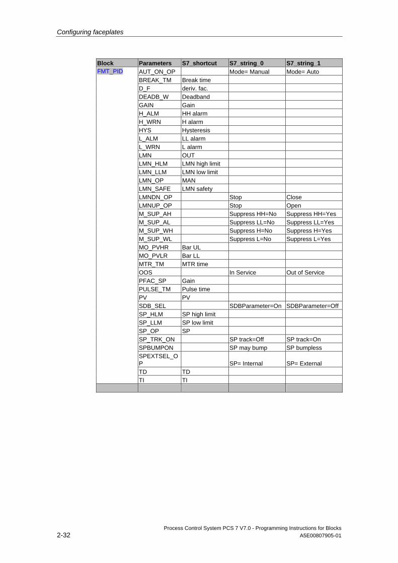
Configuring faceplates
Process Control System PCS 7 V7.0 - Programming Instructions for Blocks 2-32 A5E00807905-01
Block Parameters S7_shortcut S7_string_0 S7_string_1 AUT_ON_OP Mode= Manual Mode= Auto BREAK_TM Break time D_F deriv. fac. DEADB_W Deadband GAIN Gain H_ALM HH alarm H_WRN H alarm HYS Hysteresis L_ALM LL alarm L_WRN L alarm LMN OUT LMN_HLM LMN high limit LMN_LLM LMN low limit LMN_OP MAN LMN_SAFE LMN safety LMNDN_OP Stop Close LMNUP_OP Stop Open M_SUP_AH Suppress HH=No Suppress HH=Yes M_SUP_AL Suppress LL=No Suppress LL=Yes M_SUP_WH Suppress H=No Suppress H=Yes M_SUP_WL Suppress L=No Suppress L=Yes MO_PVHR Bar UL MO_PVLR Bar LL MTR_TM MTR time OOS In Service Out of Service PFAC_SP Gain PULSE_TM Pulse time PV PV SDB_SEL SDBParameter=On SDBParameter=Off SP_HLM SP high limit SP_LLM SP low limit SP_OP SP SP_TRK_ON SP track=Off SP track=On SPBUMPON SP may bump SP bumpless SPEXTSEL_OP SP= Internal SP= External TD TD
FMT_PID
TI TI
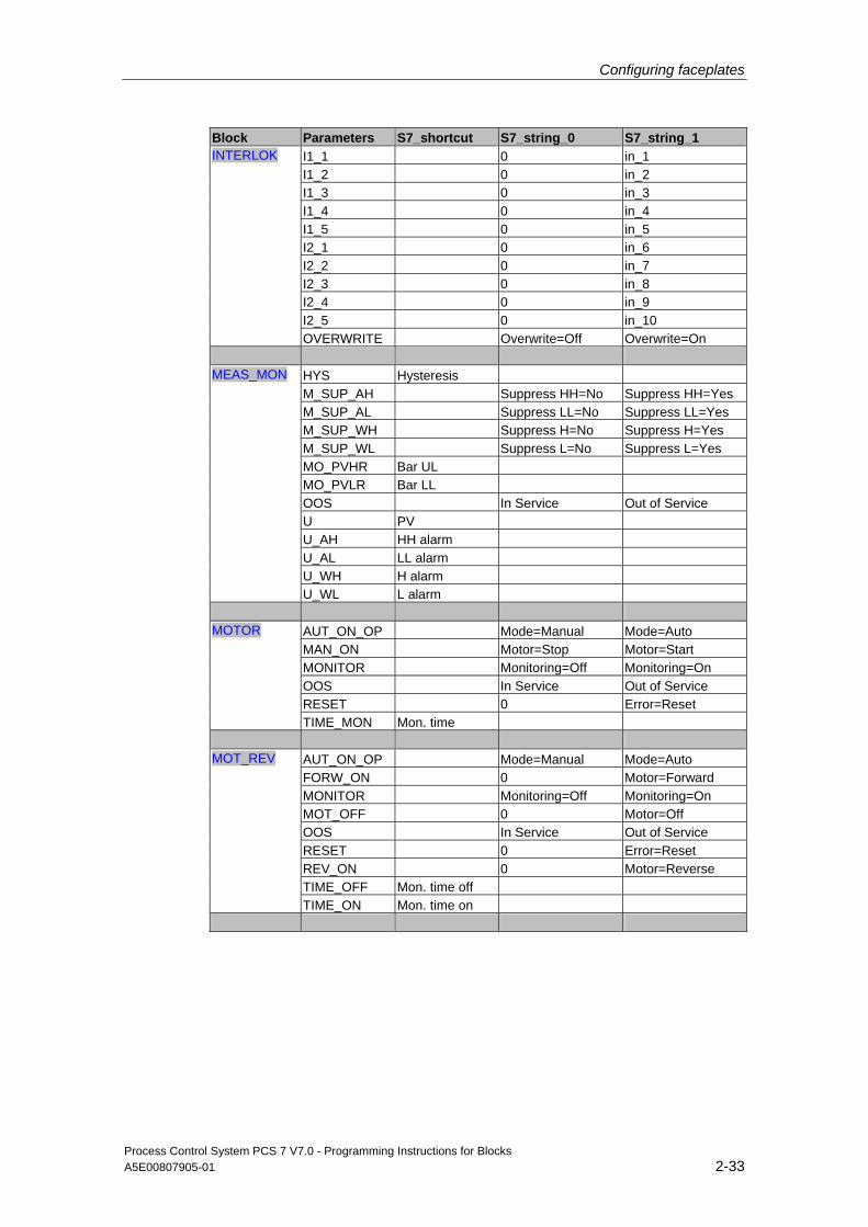
Configuring faceplates
Process Control System PCS 7 V7.0 - Programming Instructions for Blocks A5E00807905-01 2-33
Block Parameters S7_shortcut S7_string_0 S7_string_1 I1_1 0 in_1 I1_2 0 in_2 I1_3 0 in_3 I1_4 0 in_4 I1_5 0 in_5 I2_1 0 in_6 I2_2 0 in_7 I2_3 0 in_8 I2_4 0 in_9 I2_5 0 in_10
INTERLOK
OVERWRITE Overwrite=Off Overwrite=On
HYS Hysteresis M_SUP_AH Suppress HH=No Suppress HH=Yes M_SUP_AL Suppress LL=No Suppress LL=Yes M_SUP_WH Suppress H=No Suppress H=Yes M_SUP_WL Suppress L=No Suppress L=Yes MO_PVHR Bar UL MO_PVLR Bar LL OOS In Service Out of Service U PV U_AH HH alarm U_AL LL alarm U_WH H alarm
MEAS_MON
U_WL L alarm
AUT_ON_OP Mode=Manual Mode=Auto MAN_ON Motor=Stop Motor=Start MONITOR Monitoring=Off Monitoring=On OOS In Service Out of Service RESET 0 Error=Reset
MOTOR
TIME_MON Mon. time
AUT_ON_OP Mode=Manual Mode=Auto FORW_ON 0 Motor=Forward MONITOR Monitoring=Off Monitoring=On MOT_OFF 0 Motor=Off OOS In Service Out of Service RESET 0 Error=Reset REV_ON 0 Motor=Reverse TIME_OFF Mon. time off
MOT_REV
TIME_ON Mon. time on
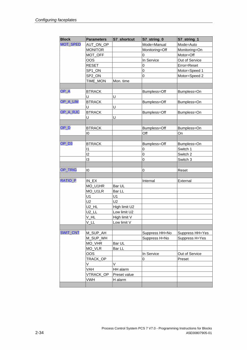
Configuring faceplates
Process Control System PCS 7 V7.0 - Programming Instructions for Blocks 2-34 A5E00807905-01
Block Parameters S7_shortcut S7_string_0 S7_string_1 AUT_ON_OP Mode=Manual Mode=Auto MONITOR Monitoring=Off Monitoring=On MOT_OFF 0 Motor=Off OOS In Service Out of Service RESET 0 Error=Reset SP1_ON 0 Motor=Speed 1 SP2_ON 0 Motor=Speed 2
MOT_SPED
TIME_MON Mon. time
BTRACK Bumpless=Off Bumpless=On OP_A U U BTRACK Bumpless=Off Bumpless=On OP_A_LIM U U BTRACK Bumpless=Off Bumpless=On OP_A_RJC U U
BTRACK Bumpless=Off Bumpless=On OP_D I0 Off On
BTRACK Bumpless=Off Bumpless=On I1 0 Switch 1
OP_D3
I2 0 Switch 2 I3 0 Switch 3
OP_TRIG I0 0 Reset
IN_EX Internal External MO_U1HR Bar UL MO_U1LR Bar LL U1 U1 U2 U2 U2_HL High limit U2 U2_LL Low limit U2 V_HL High limit V
RATIO_P
V_LL Low limit V
M_SUP_AH Suppress HH=No Suppress HH=Yes M_SUP_WH Suppress H=No Suppress H=Yes MO_VHR Bar UL MO_VLR Bar LL OOS In Service Out of Service TRACK_OP 0 Preset V V VAH HH alarm VTRACK_OP Preset value
SWIT_CNT
VWH H alarm

Configuring faceplates
Process Control System PCS 7 V7.0 - Programming Instructions for Blocks A5E00807905-01 2-35
Block Parameters S7_shortcut S7_string_0 S7_string_1 AUT_ON_OP Mode=Manual Mode=Auto MAN_OC Valve=Close Valve=Open MONITOR Monitoring=Off Monitoring=On OOS In Service Out of Service RESET 0 Error=Reset
VALVE
TIME_MON Mon. time
AUT_ON_OP Mode=Manual Mode=Auto CLOS_VAL 0 Valve=Close MONITOR Monitoring=Off Monitoring=On OOS In Service Out of Service OPEN_VAL 0 Valve=Open RESET 0 Error=Reset SS_POS STOP_VAL 0 Valve=Stop TIME_OFF Mon. time off
VAL_MOT
TIME_ON Mon. time on
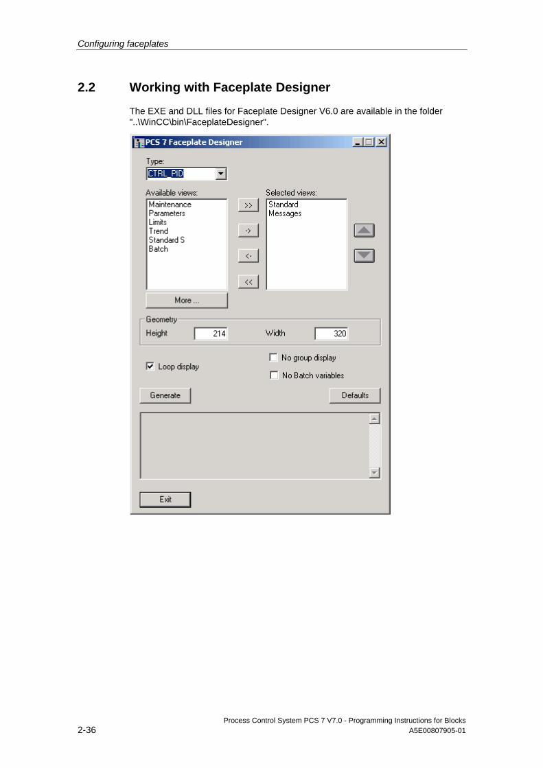
Configuring faceplates
Process Control System PCS 7 V7.0 - Programming Instructions for Blocks 2-36 A5E00807905-01
2.2 Working with Faceplate Designer
The EXE and DLL files for Faceplate Designer V6.0 are available in the folder "..\WinCC\bin\FaceplateDesigner".

Configuring faceplates
Process Control System PCS 7 V7.0 - Programming Instructions for Blocks A5E00807905-01 2-37
Procedure 1. Open WinCC Explorer to start Faceplate Designer.
2. Enter a name for the new faceplate in the "Type" combo box.
3. You can either select a name from the drop-down list of structure types of the WinCC variable database or assign a new name.
4. In the “Selected views” pane on the right side, enter the various views of the faceplate to be generated in Faceplate Designer Select these from the "Available views" pane on the left side, or create new views by clicking "Further". Configure additional view names for output to the list of views when creating multilingual projects The program outputs a corresponding message when you generate this new view
The procedure is described in the example (see chapter 2.2.1).
5. Configure the picture height and width of the views at the "Geometry" parameters The program sets the default dimensions, including the batch or message views, for example
To observe when configuring:
• The picture views are output to the group or loop display
• Globally valid pictures are used for Alarm, Batch and Trend
• Loop display generation can be suppressed. The loop display selection button is also hidden when you activate this function.
• Faceplate Designer is visualized in the language set in WinCC Explorer
• Faceplate Designer determines the user interface language currently set in WinCC and presents its dialog in the same language
• Any subsequent change of the WinCC user interface language is ignored as long as the dialog box is open
• Click "Defaults" to restore the basic settings of Faceplate Designer
• Initiate the generation of pictures by clicking "Generate" The section below shows how to generate pictures for a faceplate named "TEST" with "Selected Views = default" setting:
New picture from picture template @PG_TEST.pdl @PG_%TYPE%.pdl @PL_TEST.pdl @PL_%TYPE%.pdl @PG_TEST_OVERVIEW.pdl @PG_%Type%_OVERVIEW.pdl @PG_TEST_VIEWLIST.pdl @PG_%Type%_VIEWLIST.pdl @PG_TEST_STANDARD.pdl @PG_%Type%_%View%.pdl
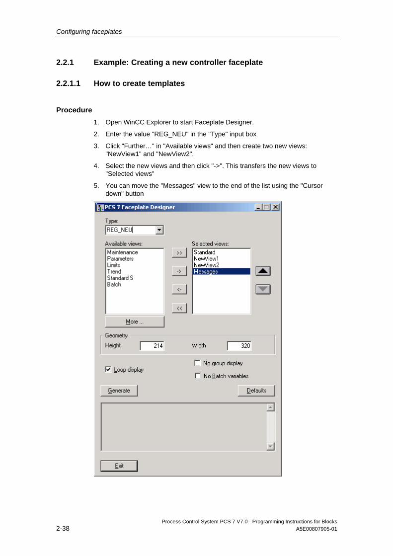
Configuring faceplates
Process Control System PCS 7 V7.0 - Programming Instructions for Blocks 2-38 A5E00807905-01
2.2.1 Example: Creating a new controller faceplate
2.2.1.1 How to create templates
Procedure 1. Open WinCC Explorer to start Faceplate Designer.
2. Enter the value "REG_NEU" in the "Type" input box
3. Click "Further…" in "Available views" and then create two new views: "NewView1" and "NewView2".
4. Select the new views and then click "->". This transfers the new views to "Selected views"
5. You can move the "Messages" view to the end of the list using the "Cursor down" button

Configuring faceplates
Process Control System PCS 7 V7.0 - Programming Instructions for Blocks A5E00807905-01 2-39
6. Click "Generate" The program generates the template pictures shown below
New picture from picture template
@PG_REG_NEU.pdl @PG_%TYPE%.pdl @PL_REG_NEU.pdl @PL_%TYPE%.pdl @PG_REG_NEU_OVERVIEW.pdl @PG_%Type%_OVERVIEW.pdl @PG_REG_NEU_VIEWLIST.pdl @PG_%Type%_VIEWLIST.pdl @PG_REG_NEU_STANDARD.pdl @PG_%Type%_%View%.pdl @PG_REG_NEU_NEUESICHT1.pdl @PG_%Type%_%View%.pdl @PG_REG_NEU_NEUESICHT2.pdl @PG_%Type%_%View%.pdl
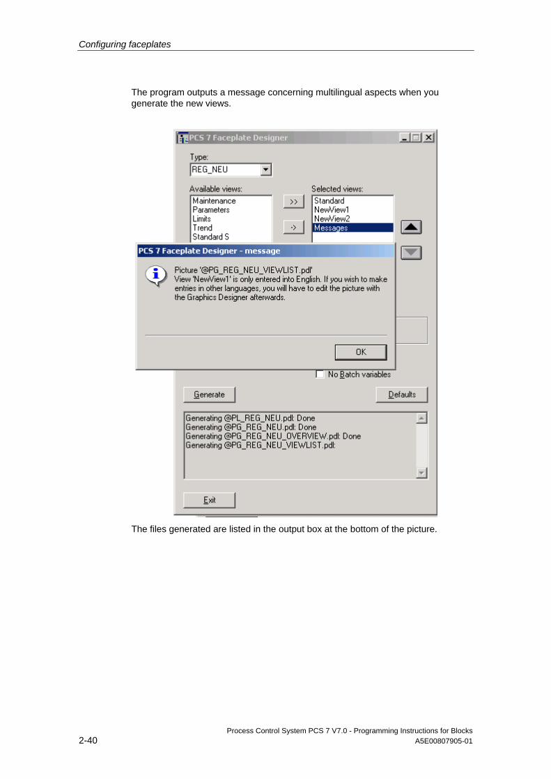
Configuring faceplates
Process Control System PCS 7 V7.0 - Programming Instructions for Blocks 2-40 A5E00807905-01
The program outputs a message concerning multilingual aspects when you generate the new views.
The files generated are listed in the output box at the bottom of the picture.
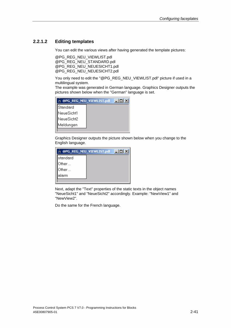
Configuring faceplates
Process Control System PCS 7 V7.0 - Programming Instructions for Blocks A5E00807905-01 2-41
2.2.1.2 Editing templates
You can edit the various views after having generated the template pictures:
@PG_REG_NEU_VIEWLIST.pdl @PG_REG_NEU_STANDARD.pdl @PG_REG_NEU_NEUESICHT1.pdl @PG_REG_NEU_NEUESICHT2.pdl
You only need to edit the "@PG_REG_NEU_VIEWLIST.pdl" picture if used in a multilingual system. The example was generated in German language. Graphics Designer outputs the pictures shown below when the "German" language is set.
Graphics Designer outputs the picture shown below when you change to the English language.
Next, adapt the "Text" properties of the static texts in the object names "NeueSicht1" and "NeueSicht2" accordingly. Example: "NewView1" and "NewView2".
Do the same for the French language.
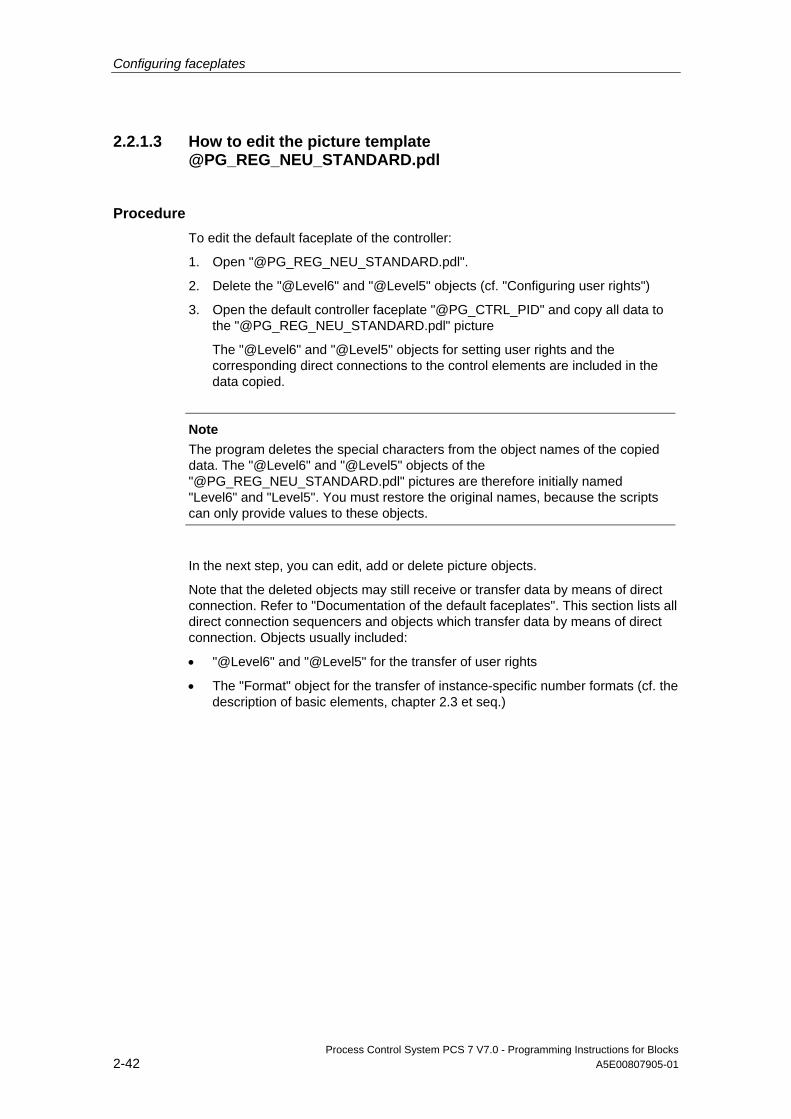
Configuring faceplates
Process Control System PCS 7 V7.0 - Programming Instructions for Blocks 2-42 A5E00807905-01
2.2.1.3 How to edit the picture template @PG_REG_NEU_STANDARD.pdl
Procedure To edit the default faceplate of the controller:
1. Open "@PG_REG_NEU_STANDARD.pdl".
2. Delete the "@Level6" and "@Level5" objects (cf. "Configuring user rights")
3. Open the default controller faceplate "@PG_CTRL_PID" and copy all data to the "@PG_REG_NEU_STANDARD.pdl" picture
The "@Level6" and "@Level5" objects for setting user rights and the corresponding direct connections to the control elements are included in the data copied.
Note
The program deletes the special characters from the object names of the copied data. The "@Level6" and "@Level5" objects of the "@PG_REG_NEU_STANDARD.pdl" pictures are therefore initially named "Level6" and "Level5". You must restore the original names, because the scripts can only provide values to these objects.
In the next step, you can edit, add or delete picture objects.
Note that the deleted objects may still receive or transfer data by means of direct connection. Refer to "Documentation of the default faceplates". This section lists all direct connection sequencers and objects which transfer data by means of direct connection. Objects usually included:
• "@Level6" and "@Level5" for the transfer of user rights
• The "Format" object for the transfer of instance-specific number formats (cf. the description of basic elements, chapter 2.3 et seq.)
Configuring faceplates
Process Control System PCS 7 V7.0 - Programming Instructions for Blocks A5E00807905-01 2-43
2.2.1.4 How to edit the picture @PG_REG_NEU_NEUESICHT1.pdl
You can copy objects from the "@PCS7Elements.pdl" picture template and assign dynamic attributes to these copies.
Procedure 1. Open the "@PG_REG_NEU_NEUESICHT1.pdl" and "@PCS7Elements.pdl"
pictures in WinCC Graphics Designer.
2. Select Window > Align horizontally to align the pictures horizontally
3. Copy the required picture objects from the "@PCS7Elements.pdl" to the "@PG_REG_NEU_NEUESICHT1.pdl" picture.
4. Assign meaningful, object-relevant object names.
5. Position the objects
6. Interconnect the dynamic attributes of the picture elements with the AS parameters
7. Configure the "User rights sequencers" based on the "@Level5" and "@Level6" objects
8. Save the picture
2.2.1.5 Dynamic update of faceplates
There are several methods of updating faceplates dynamically:
• The extension of the variable required is known
Open the object properties dialog to assign dynamic attributes to an object such as a bar graph. In the "Dynamics" column of the properties dialog box, double-click the bulb icon of the attribute required. On the input box, you can now enter the dot plus extension. Example: .PV_IN.
• Variable from the variable list
The variable list is usually deployed for the configuration of process pictures. However, this list returns all variables. Right-click the glow lamp icon on the properties dialog box and then select "Variable".
Locate the relevant variable and then double-click this entry. As the dynamic attribute contains the full variable name, delete the text leading the file name extension dot.
Configuring faceplates
Process Control System PCS 7 V7.0 - Programming Instructions for Blocks 2-44 A5E00807905-01
2.2.1.6 Creating a loop view
Procedure The "Picture selection with process tag" function lets you change to the loop view. It is advisable for this reason to generate a loop view, regardless of whether you only require a single view for the faceplate.
1. Generate the pictures without loop view in Faceplate Designer. The program generates the group picture view without loop view selection button.
2. Repeat generation and include the loop display view Click "No" for all pictures, except when prompted to "Overwrite loop display".
2.2.1.7 Generating an additional view
Procedure Recommended procedure for generating an additional view after having edited the existing views:
1. Enter the type name and the selected views in Faceplate Designer similar to the initial generation
2. Add the new view to the entries and then start generation
During generation, the program outputs a message asking you to confirm overwriting of any existing file.
3. Acknowledge this message with "No"

Configuring faceplates
Process Control System PCS 7 V7.0 - Programming Instructions for Blocks A5E00807905-01 2-45
2.3 Basic elements
2.3.1 Storage location of the basic elements
All basic elements are saved to the "@PCS7Elements.pdl" picture template. The picture is saved to the ”\Wincc\options\pdl\FaceplateDesigner_V6" folder and copied to the project by OS Project Editor.
2.3.2 Display and control of analog values
Object type Object name Picture name PCS7_AnalogValue PCS7_AnalogValue1
PCS7_AnalogValue2 PCS7_AnalogValue3
@PCS7Elements.pdl
Example of parameter settings at the identical "PCS7_AnalogValue1" and "PCS7_AnalogValue2" objects:
• "PCS7_AnalogValue1" for analog value input
• "PCS7_AnalogValue2" for analog value display
The floating-point format of the I/O field is used at both objects. You can use these objects for numerical representation and input functions which are not modified by the process, as the floating point function does not have a negative impact.
It is recommended to use the "PCS7_AnalogValue3" object which was created using the new AdvancedAnalogDisplay function. With this function, only the integer digits float, whereas the decimal places can be configured instance-specific.
Settings to make when using the function only for analog displays:
• Set the "Operator input enable" property to FALSE state
• Set the value "gray" at the "Background color" property
When used for analog value input, the program calls the "PCS7_OpenInputBoxAnalog_V6" script on mouse click.
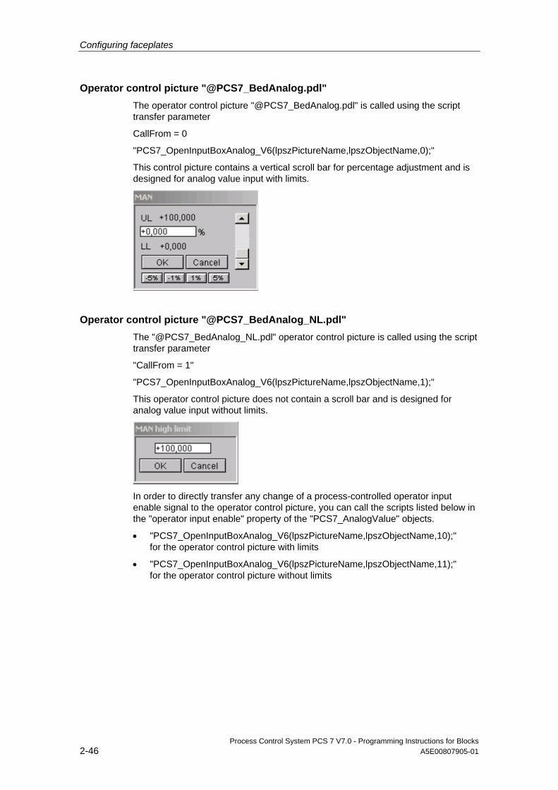
Configuring faceplates
Process Control System PCS 7 V7.0 - Programming Instructions for Blocks 2-46 A5E00807905-01
Operator control picture "@PCS7_BedAnalog.pdl" The operator control picture "@PCS7_BedAnalog.pdl" is called using the script transfer parameter
CallFrom = 0
"PCS7_OpenInputBoxAnalog_V6(lpszPictureName,lpszObjectName,0);"
This control picture contains a vertical scroll bar for percentage adjustment and is designed for analog value input with limits.
Operator control picture "@PCS7_BedAnalog_NL.pdl" The "@PCS7_BedAnalog_NL.pdl" operator control picture is called using the script transfer parameter
"CallFrom = 1"
"PCS7_OpenInputBoxAnalog_V6(lpszPictureName,lpszObjectName,1);"
This operator control picture does not contain a scroll bar and is designed for analog value input without limits.
In order to directly transfer any change of a process-controlled operator input enable signal to the operator control picture, you can call the scripts listed below in the "operator input enable" property of the "PCS7_AnalogValue" objects.
• "PCS7_OpenInputBoxAnalog_V6(lpszPictureName,lpszObjectName,10);" for the operator control picture with limits
• "PCS7_OpenInputBoxAnalog_V6(lpszPictureName,lpszObjectName,11);" for the operator control picture without limits
Configuring faceplates
Process Control System PCS 7 V7.0 - Programming Instructions for Blocks A5E00807905-01 2-47
You cannot edit the value shown in the operator control picture if operator input is disabled when you select the picture.
Properties Function ProcessValue/OutputValue Structure element of the controlled analog value
ProcessValue/VisibleValue Structure element of the dynamically updated analog
value Limits/UpperLimit Structure element for the "high" limit of analog value
input Limits/LowerLimit Structure element for the “low” limit of analog value
input Other/OP_enabled Input enable on AS side, for example "Q_SP_OP" or
permanently set to "No" if only used for display functions
Other/Display_Analog_Value Must always be set visible Other/Password Do not use. This item is handled by the access
control functions. Other/Display_Line Display of the blue line Other/Line thickness You can adjust the line thickness Other/Open_InpBox_from_Bar Properties for the indirect call of operator input picture
"@PCS7_BedAnalog.pdl", for example, using a control bar function
Font/Text Labeling of the I/O field (setpoint) Font/Unit Unit of the analog value, dynamically set at
.MEMBER#unit, for example, .SP_OP#unit Font/X-Alignment_Text left aligned if several I/O boxes are arranged vertically
right aligned for single analog values
Colors/Fontcolor Font color selection Colors /Linecolor Line color selection Colors /Background_Value Selection of the background color "Value". Updated
dynamically by the script upon "Change of operator input enable“ events
Colors /Fontcolor_Value Selection of the font color "Value". Geometry/Width_Analogvalue Overall width of the analog field Geometry/Width_Line_Text The length of the line and text can be set Geometry/PositionX1_Line_Text Must be adapted when the text and line length
change Geometry/PositionY1_Line Line height compared to the font
The "Font/Text" property is set by default at sample parameter ".SP_OP#shortcut". The display text of the block icon and the header of the picture for analog value input, are read from the AS (s7_shortcut). When using variables without display text, for example, PV_IN, delete the interconnection and configure the text directly in WinCC. If necessary, generate the text in three languages.

Configuring faceplates
Process Control System PCS 7 V7.0 - Programming Instructions for Blocks 2-48 A5E00807905-01
The program also calls the "PCS7_OpenInputBoxAnalog_V6" script when it detects a change to the "Open_BedBox_from_Bar" property. The program verifies that operator input is enabled before it executes the script.
The script can also be used for indirect input. Example: the program calls the corresponding control picture when it detects the "Click on setpoint bar graph" event. (cf. the description of the double bar graph which displays both the setpoint and the process value). A change to the property is there diverted to the “Open_InpBox_from_Bar” property by means of direct connection.
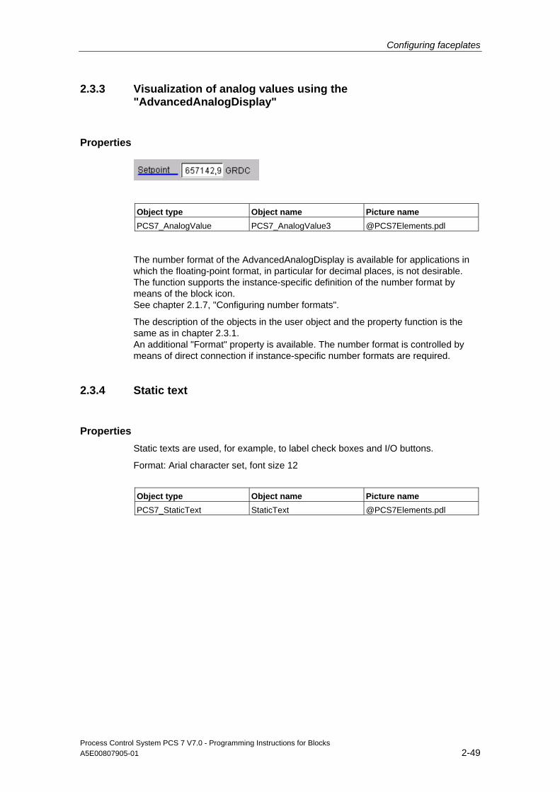
Configuring faceplates
Process Control System PCS 7 V7.0 - Programming Instructions for Blocks A5E00807905-01 2-49
2.3.3 Visualization of analog values using the "AdvancedAnalogDisplay"
Properties
Object type Object name Picture name PCS7_AnalogValue PCS7_AnalogValue3 @PCS7Elements.pdl
The number format of the AdvancedAnalogDisplay is available for applications in which the floating-point format, in particular for decimal places, is not desirable. The function supports the instance-specific definition of the number format by means of the block icon. See chapter 2.1.7, "Configuring number formats".
The description of the objects in the user object and the property function is the same as in chapter 2.3.1. An additional "Format" property is available. The number format is controlled by means of direct connection if instance-specific number formats are required.
2.3.4 Static text
Properties
Static texts are used, for example, to label check boxes and I/O buttons.
Format: Arial character set, font size 12
Object type Object name Picture name PCS7_StaticText StaticText @PCS7Elements.pdl
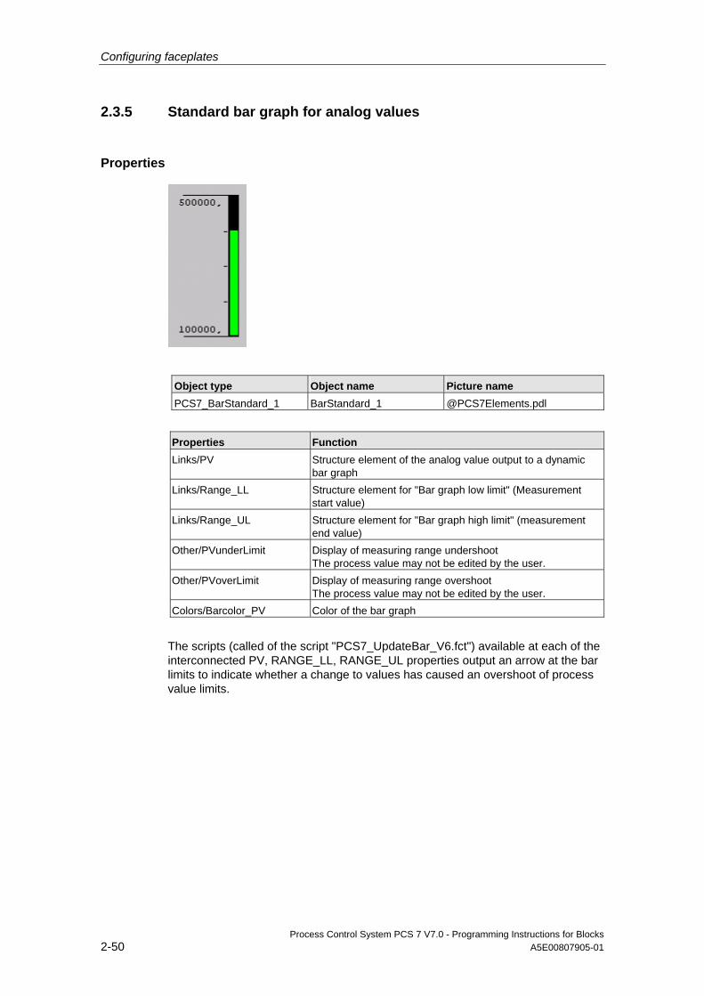
Configuring faceplates
Process Control System PCS 7 V7.0 - Programming Instructions for Blocks 2-50 A5E00807905-01
2.3.5 Standard bar graph for analog values
Properties
Object type Object name Picture name PCS7_BarStandard_1 BarStandard_1 @PCS7Elements.pdl
Properties Function Links/PV Structure element of the analog value output to a dynamic
bar graph Links/Range_LL Structure element for "Bar graph low limit" (Measurement
start value) Links/Range_UL Structure element for "Bar graph high limit" (measurement
end value) Other/PVunderLimit Display of measuring range undershoot
The process value may not be edited by the user. Other/PVoverLimit Display of measuring range overshoot
The process value may not be edited by the user. Colors/Barcolor_PV Color of the bar graph
The scripts (called of the script "PCS7_UpdateBar_V6.fct") available at each of the interconnected PV, RANGE_LL, RANGE_UL properties output an arrow at the bar limits to indicate whether a change to values has caused an overshoot of process value limits.
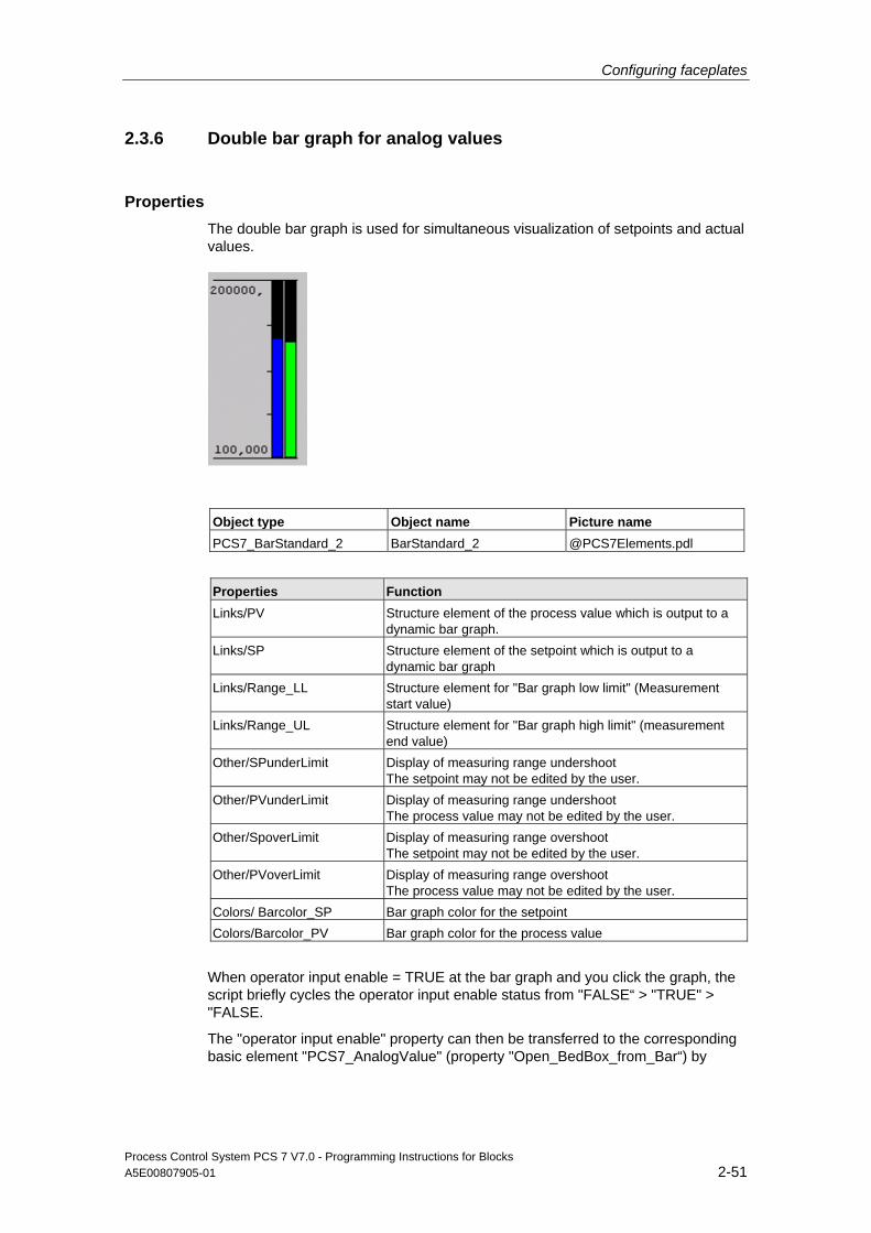
Configuring faceplates
Process Control System PCS 7 V7.0 - Programming Instructions for Blocks A5E00807905-01 2-51
2.3.6 Double bar graph for analog values
Properties The double bar graph is used for simultaneous visualization of setpoints and actual values.
Object type Object name Picture name PCS7_BarStandard_2 BarStandard_2 @PCS7Elements.pdl
Properties Function Links/PV Structure element of the process value which is output to a
dynamic bar graph. Links/SP Structure element of the setpoint which is output to a
dynamic bar graph Links/Range_LL Structure element for "Bar graph low limit" (Measurement
start value) Links/Range_UL Structure element for "Bar graph high limit" (measurement
end value) Other/SPunderLimit Display of measuring range undershoot
The setpoint may not be edited by the user. Other/PVunderLimit Display of measuring range undershoot
The process value may not be edited by the user. Other/SpoverLimit Display of measuring range overshoot
The setpoint may not be edited by the user. Other/PVoverLimit Display of measuring range overshoot
The process value may not be edited by the user. Colors/ Barcolor_SP Bar graph color for the setpoint Colors/Barcolor_PV Bar graph color for the process value
When operator input enable = TRUE at the bar graph and you click the graph, the script briefly cycles the operator input enable status from "FALSE“ > "TRUE" > "FALSE.
The "operator input enable" property can then be transferred to the corresponding basic element "PCS7_AnalogValue" (property "Open_BedBox_from_Bar“) by

Configuring faceplates
Process Control System PCS 7 V7.0 - Programming Instructions for Blocks 2-52 A5E00807905-01
means of direct connection, were it initiates the call of the analog value input box for setpoint input (see also the description of analog value input in chapter 2.3.1).
The bar graph display is supplemented by arrows which indicate values above and below bar graph limits.
The scripts (call of the script "PCS7_UpdateBar.fct") stored in each one of the interconnected properties PV, SP, RANGE_LL and RANGE_UL output arrows at the bar graph limits to indicate any measuring range overshoot/undershoot when values change.
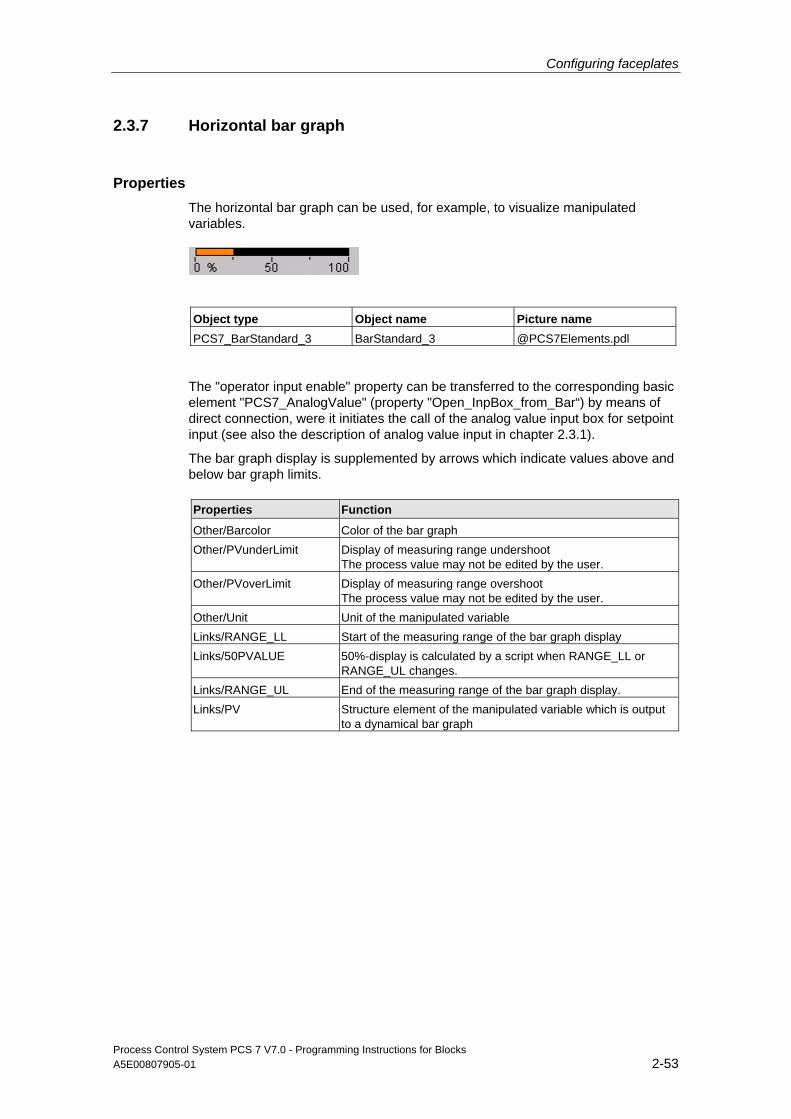
Configuring faceplates
Process Control System PCS 7 V7.0 - Programming Instructions for Blocks A5E00807905-01 2-53
2.3.7 Horizontal bar graph
Properties The horizontal bar graph can be used, for example, to visualize manipulated variables.
Object type Object name Picture name PCS7_BarStandard_3 BarStandard_3 @PCS7Elements.pdl
The "operator input enable" property can be transferred to the corresponding basic element "PCS7_AnalogValue" (property "Open_InpBox_from_Bar“) by means of direct connection, were it initiates the call of the analog value input box for setpoint input (see also the description of analog value input in chapter 2.3.1).
The bar graph display is supplemented by arrows which indicate values above and below bar graph limits.
Properties Function Other/Barcolor Color of the bar graph Other/PVunderLimit Display of measuring range undershoot
The process value may not be edited by the user. Other/PVoverLimit Display of measuring range overshoot
The process value may not be edited by the user. Other/Unit Unit of the manipulated variable Links/RANGE_LL Start of the measuring range of the bar graph display Links/50PVALUE 50%-display is calculated by a script when RANGE_LL or
RANGE_UL changes. Links/RANGE_UL End of the measuring range of the bar graph display. Links/PV Structure element of the manipulated variable which is output
to a dynamical bar graph
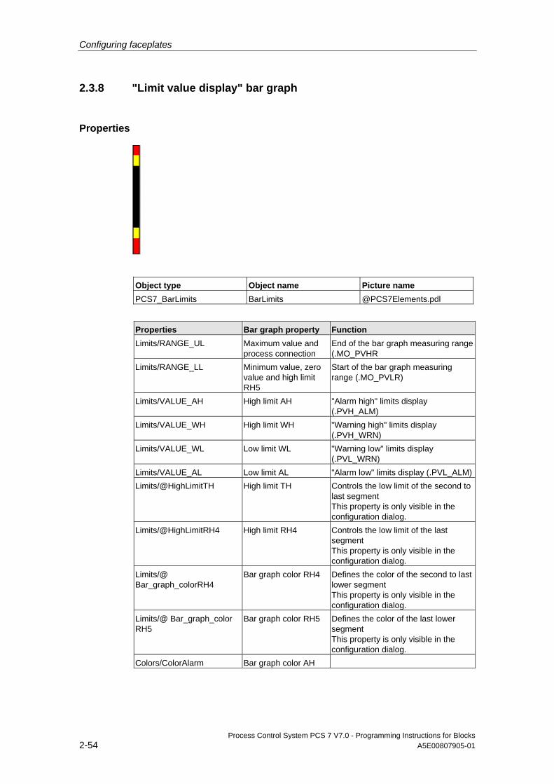
Configuring faceplates
Process Control System PCS 7 V7.0 - Programming Instructions for Blocks 2-54 A5E00807905-01
2.3.8 "Limit value display" bar graph
Properties
Object type Object name Picture name PCS7_BarLimits BarLimits @PCS7Elements.pdl
Properties Bar graph property Function Limits/RANGE_UL Maximum value and
process connection End of the bar graph measuring range (.MO_PVHR
Limits/RANGE_LL Minimum value, zero value and high limit RH5
Start of the bar graph measuring range (.MO_PVLR)
Limits/VALUE_AH High limit AH "Alarm high" limits display (.PVH_ALM)
Limits/VALUE_WH High limit WH "Warning high" limits display (.PVH_WRN)
Limits/VALUE_WL Low limit WL "Warning low" limits display (.PVL_WRN)
Limits/VALUE_AL Low limit AL "Alarm low" limits display (.PVL_ALM)Limits/@HighLimitTH High limit TH Controls the low limit of the second to
last segment This property is only visible in the configuration dialog.
Limits/@HighLimitRH4 High limit RH4 Controls the low limit of the last segment This property is only visible in the configuration dialog.
Limits/@ Bar_graph_colorRH4
Bar graph color RH4 Defines the color of the second to last lower segment This property is only visible in the configuration dialog.
Limits/@ Bar_graph_color RH5
Bar graph color RH5 Defines the color of the last lower segment This property is only visible in the configuration dialog.
Colors/ColorAlarm Bar graph color AH
Configuring faceplates
Process Control System PCS 7 V7.0 - Programming Instructions for Blocks A5E00807905-01 2-55
Properties Bar graph property Function Colors/ColorWarning Bar graph color WH Colors/ ColorBackground
Bar graph color TH Color of the middle segment
The script "PCS7_UpdateBarLimits_V6" is called when the low limit values "VALUE_WL", "VALUE_AL" and "RANGE_LL" change, as the "Alarm" and "Low Limit Warning " bar graph display cannot be generated by means of the standard bar graph. A script is not required for the high limit values.
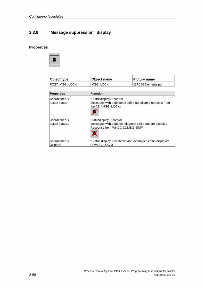
Configuring faceplates
Process Control System PCS 7 V7.0 - Programming Instructions for Blocks 2-56 A5E00807905-01
2.3.9 "Message suppression" display
Properties
Object type Object name Picture name PCS7_MSG_LOCK MSG_LOCK @PCS7Elements.pdl
Properties Function Userdefined2/ actual status
"Statusdisplay2" control Messages with a diagonal strike-out disable requests from the AS (.MSG_LOCK)
Userdefined2/ actual status1
Statusdisplay3" control Messages with a double diagonal strike-out are disabled Response from WinCC (.QMSG_SUP)
Userdefined2/ Display1
"Status display3" is shown and overlays "Status display2" (.QMSG_LOCK)
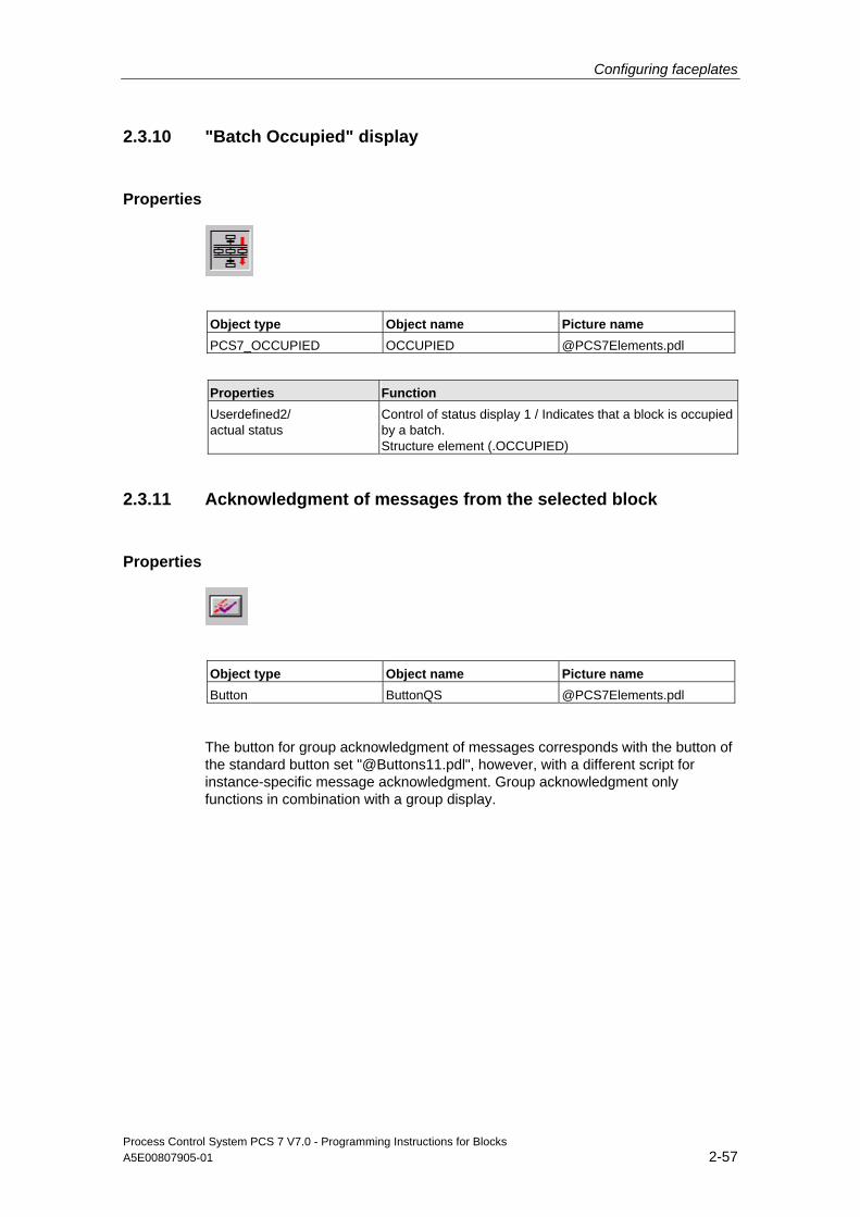
Configuring faceplates
Process Control System PCS 7 V7.0 - Programming Instructions for Blocks A5E00807905-01 2-57
2.3.10 "Batch Occupied" display
Properties
Object type Object name Picture name PCS7_OCCUPIED OCCUPIED @PCS7Elements.pdl
Properties Function Userdefined2/ actual status
Control of status display 1 / Indicates that a block is occupied by a batch. Structure element (.OCCUPIED)
2.3.11 Acknowledgment of messages from the selected block
Properties
Object type Object name Picture name Button ButtonQS @PCS7Elements.pdl
The button for group acknowledgment of messages corresponds with the button of the standard button set "@Buttons11.pdl", however, with a different script for instance-specific message acknowledgment. Group acknowledgment only functions in combination with a group display.
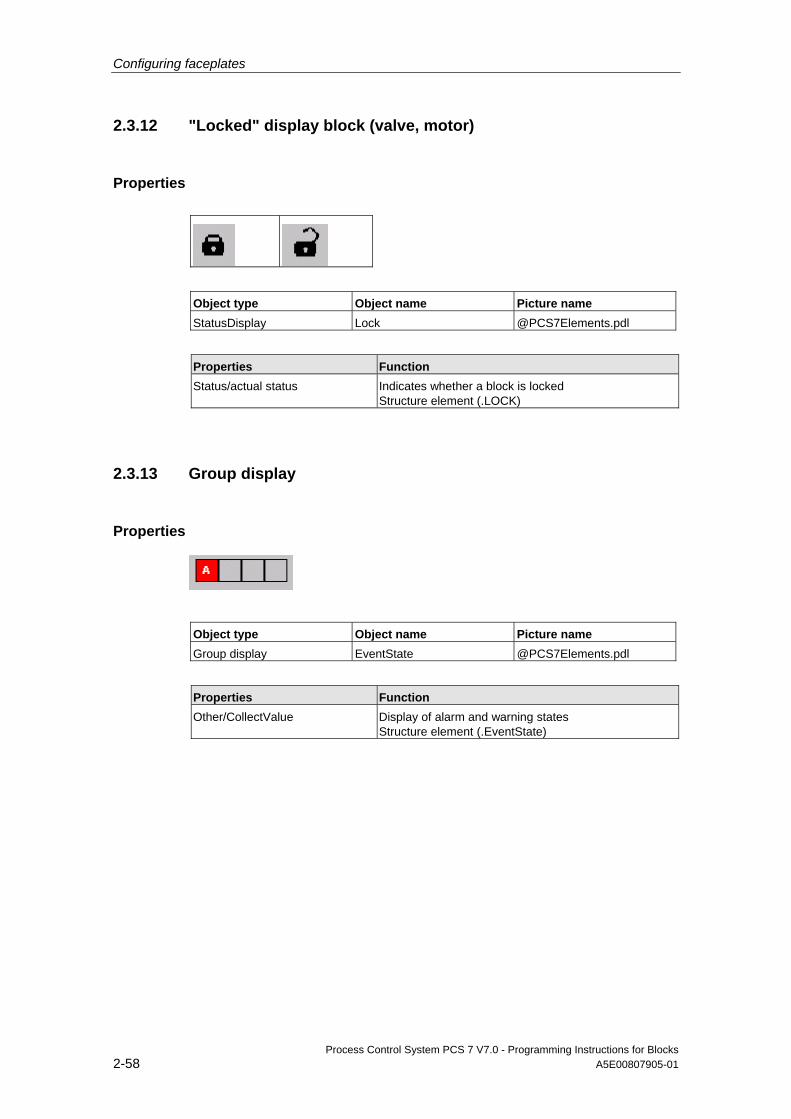
Configuring faceplates
Process Control System PCS 7 V7.0 - Programming Instructions for Blocks 2-58 A5E00807905-01
2.3.12 "Locked" display block (valve, motor)
Properties
Object type Object name Picture name StatusDisplay Lock @PCS7Elements.pdl
Properties Function Status/actual status Indicates whether a block is locked
Structure element (.LOCK)
2.3.13 Group display
Properties
Object type Object name Picture name Group display EventState @PCS7Elements.pdl
Properties Function Other/CollectValue Display of alarm and warning states
Structure element (.EventState)
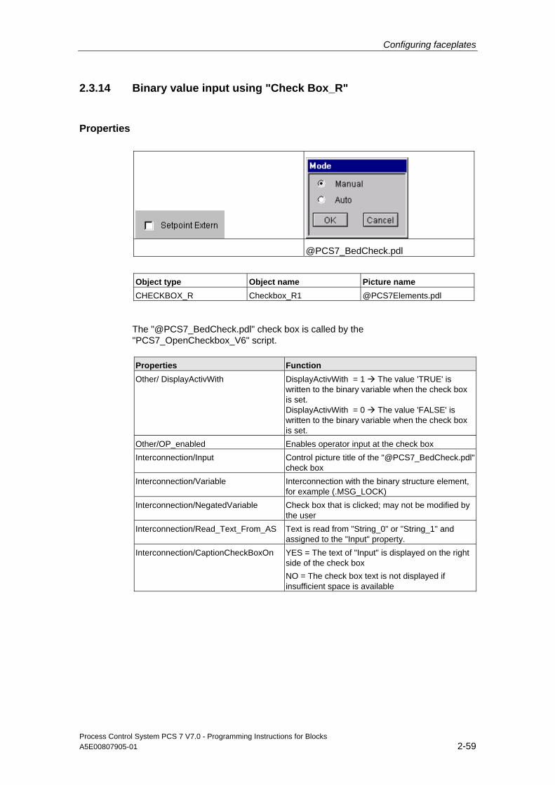
Configuring faceplates
Process Control System PCS 7 V7.0 - Programming Instructions for Blocks A5E00807905-01 2-59
2.3.14 Binary value input using "Check Box_R"
Properties
@PCS7_BedCheck.pdl
Object type Object name Picture name CHECKBOX_R Checkbox_R1 @PCS7Elements.pdl
The "@PCS7_BedCheck.pdl" check box is called by the "PCS7_OpenCheckbox_V6" script. Properties Function Other/ DisplayActivWith DisplayActivWith = 1 The value 'TRUE' is
written to the binary variable when the check box is set. DisplayActivWith = 0 The value 'FALSE' is written to the binary variable when the check box is set.
Other/OP_enabled Enables operator input at the check box Interconnection/Input Control picture title of the "@PCS7_BedCheck.pdl"
check box Interconnection/Variable Interconnection with the binary structure element,
for example (.MSG_LOCK) Interconnection/NegatedVariable Check box that is clicked; may not be modified by
the user Interconnection/Read_Text_From_AS Text is read from "String_0" or "String_1" and
assigned to the "Input" property. Interconnection/CaptionCheckBoxOn YES = The text of "Input" is displayed on the right
side of the check box NO = The check box text is not displayed if insufficient space is available
Configuring faceplates
Process Control System PCS 7 V7.0 - Programming Instructions for Blocks 2-60 A5E00807905-01
You select the internal option “Inverted Variable” clicking on the check box. The status of the binary variable to be controlled is determined and written back to "Inverted Variable" ("Interconnection/NegatedVariable" property). When the "Interconnection/Variable” property changes and a picture is selected, a script is executed to update the display of the "NegatedVariable" (see also the Check_Box flow chart). The "Interconnection/Variable” property must be set by the configuration to "unequal 1“ and "unequal 0“ (0x8) to ensure that the script is always executed when a picture is selected.
The texts used to label the check boxes are read from parameter attributes "String_0" and "String_1" of the block instance.
Labeling of the check box Rules of check box labeling:
• When you set "Read_Text_From_AS" = 1 and "DisplayActivWith = 1", the program outputs the entire text of "String_1" on the right side of the check box
• When "DisplayActivWith = 0", the entire text of "String_0" is output on the right side of the check box
• When property "Read_Text_From_AS" = 0, the program outputs the text configured at "Input" You must set these states in order to display output parameters, as a "String_0" or "String_1" does not exist at this function and you would therefore generate scripting errors You also have to make sure that you do not enable the check box for operator input in this case
Rules of check box labeling: • When the text in "String_0" and "String_1" contains a "=“ character, the string
text on the right side of the "=“ character is used to label the check boxes
• If the text of the strings does not contain a "=“ character the full text is used to label the check boxes
Rules for the control picture title: • If the text of the "String_0" and "String_1" contains a "=“ character, the text to
the left of the "=“ character forms the title of the input box, that is, when "DisplayActivWith = 1" at "String_1" and "DisplayActivWith = 0" at "String_0"
• If the text of the strings does not contain a "=“ character, the check box labeling text is used
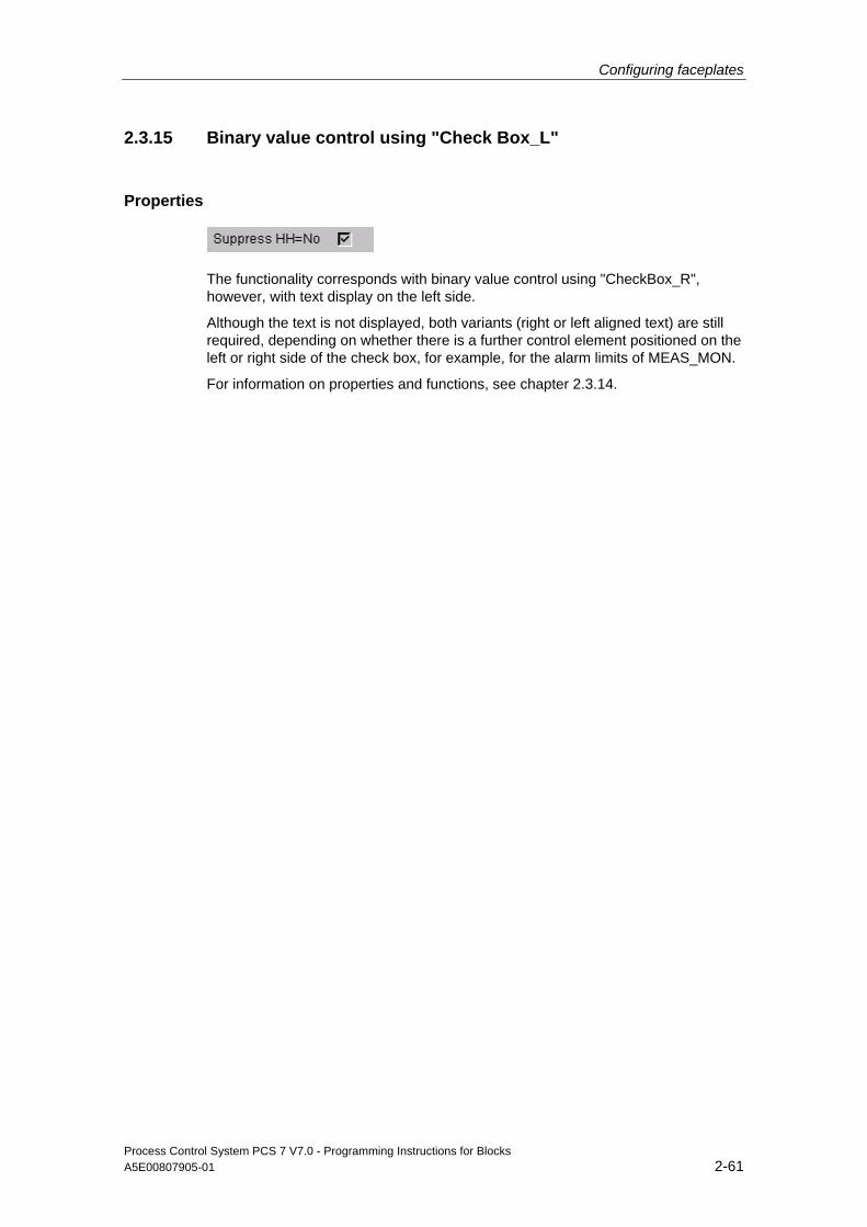
Configuring faceplates
Process Control System PCS 7 V7.0 - Programming Instructions for Blocks A5E00807905-01 2-61
2.3.15 Binary value control using "Check Box_L"
Properties
The functionality corresponds with binary value control using "CheckBox_R", however, with text display on the left side.
Although the text is not displayed, both variants (right or left aligned text) are still required, depending on whether there is a further control element positioned on the left or right side of the check box, for example, for the alarm limits of MEAS_MON.
For information on properties and functions, see chapter 2.3.14.
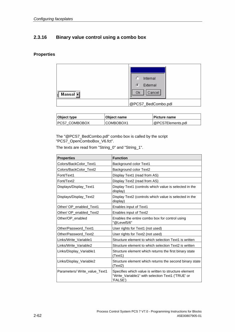
Configuring faceplates
Process Control System PCS 7 V7.0 - Programming Instructions for Blocks 2-62 A5E00807905-01
2.3.16 Binary value control using a combo box
Properties
@PCS7_BedCombo.pdl
Object type Object name Picture name PCS7_COMBOBOX COMBOBOX1 @PCS7Elements.pdl
The "@PCS7_BedCombo.pdl" combo box is called by the script "PCS7_OpenComboBox_V6.fct". The texts are read from "String_0" and "String_1". Properties Function Colors/BackColor_Text1 Background color Text1 Colors/BackColor_Text2 Background color Text2 Font/Text1 Display Text1 (read from AS) Font/Text2 Display Text2 (read from AS) Displays/Display_Text1 Display Text1 (controls which value is selected in the
display) Displays/Display_Text2 Display Text2 (controls which value is selected in the
display) Other/ OP_enabled_Text1 Enables input of Text1 Other/ OP_enabled_Text2 Enables input of Text2 Other/OP_enabled Enables the entire combo box for control using
"@Level5/6" Other/Password_Text1 User rights for Text1 (not used) Other/Password_Text2 User rights for Text2 (not used) Links/Write_Variable1 Structure element to which selection Text1 is written Links/Write_Variable2 Structure element to which selection Text2 is written Links/Display_Variable1 Structure element which returns the first binary state
(Text1) Links/Display_Variable2 Structure element which returns the second binary state
(Text2) Parameters/ Write_value_Text1 Specifies which value is written to structure element
"Write_Variable1“ with selection Text1 ('TRUE' or 'FALSE')
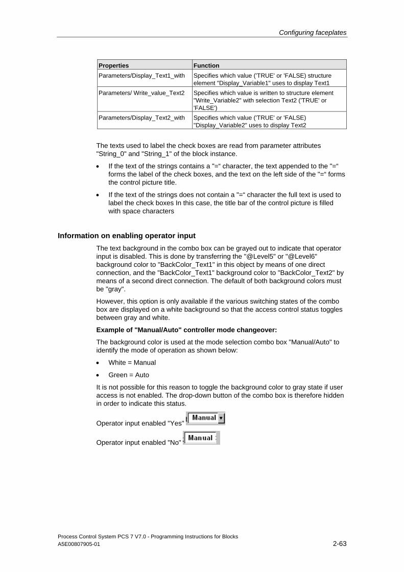
Configuring faceplates
Process Control System PCS 7 V7.0 - Programming Instructions for Blocks A5E00807905-01 2-63
Properties Function Parameters/Display_Text1_with Specifies which value ('TRUE' or 'FALSE) structure
element "Display_Variable1" uses to display Text1 Parameters/ Write_value_Text2 Specifies which value is written to structure element
"Write_Variable2" with selection Text2 ('TRUE' or 'FALSE')
Parameters/Display_Text2_with Specifies which value ('TRUE' or 'FALSE) "Display_Variable2" uses to display Text2
The texts used to label the check boxes are read from parameter attributes "String_0" and "String_1" of the block instance.
• If the text of the strings contains a "=“ character, the text appended to the "=“ forms the label of the check boxes, and the text on the left side of the "=“ forms the control picture title.
• If the text of the strings does not contain a "=“ character the full text is used to label the check boxes In this case, the title bar of the control picture is filled with space characters
Information on enabling operator input The text background in the combo box can be grayed out to indicate that operator input is disabled. This is done by transferring the "@Level5" or "@Level6" background color to "BackColor_Text1" in this object by means of one direct connection, and the "BackColor_Text1" background color to "BackColor_Text2" by means of a second direct connection. The default of both background colors must be "gray".
However, this option is only available if the various switching states of the combo box are displayed on a white background so that the access control status toggles between gray and white.
Example of "Manual/Auto" controller mode changeover:
The background color is used at the mode selection combo box "Manual/Auto" to identify the mode of operation as shown below:
• White = Manual
• Green = Auto
It is not possible for this reason to toggle the background color to gray state if user access is not enabled. The drop-down button of the combo box is therefore hidden in order to indicate this status.
Operator input enabled "Yes"
Operator input enabled "No"

Configuring faceplates
Process Control System PCS 7 V7.0 - Programming Instructions for Blocks 2-64 A5E00807905-01
2.3.17 Binary value control using a combo box (3ComboBox)
Properties
@PCS7_3BedCombo.pdl
Object type Object name Picture name PCS7_3COMBOBOX 3COMBOBOX1 @PCS7Elements.pdl
The "@PCS7_3BedCombo.pdl" combo box is called in the "PCS7_Open3ComboBox_V6.fct" script.
The texts are read from "String_0" and "String_1".
Properties Function Colors/BackColor_Text1 Background color Text1 Colors/BackColor_Text2 Background color Text2 Colors/BackColor_Text3 Background color Text3. Font/Text1 Display Text1 (read from AS) Font/Text2 Display Text2 (read from AS) Font/Text3 Display text for Text3 (read from AS) Displays/Display_Text1 Display text1 (controls which value is selected in the
display) Displays/Display_Text2 Display Text2 (controls which value is selected in the
display) Displays/Display_Text3 Display Text3 (controls which value is selected in the
display) Other/ OP_enabled_Text1 Enables operator input of Text1 Other/ OP_enabled_Text2 Enables operator input of Text2 Other/OP_enabled_Text3 Enables operator input of Text3. Other/OP_enabled Enables operator input at the entire combo box for
control using "@Level5/6" Other/Password_Text1 User rights for Text1 (not used) Other/Password_Text2 User rights for Text2 (not used) Other/Password_Text3 User rights for Text3 (not used) Links/Write_Variable1 Structure element to which selection Text1 is written
Configuring faceplates
Process Control System PCS 7 V7.0 - Programming Instructions for Blocks A5E00807905-01 2-65
Properties Function Links/Write_Variable2 Structure element to which selection Text2 is written Links/Write_Variable3 Structure element to which selection Text3 is written Links/Display_Variable1 Structure element which returns the first binary state
(Text1) Links/Display_Variable2 Structure element which returns the second binary state
(Text2) Links/Display_Variable3 Structure element which returns the second binary state
(Text3) Parameters/ Write_value_Text1 Specifies which value is written to structure element
"Write_Variable1“ with selection Text1 ('TRUE' or 'FALSE')
Parameters/Display_Text1_with Specifies which value ('TRUE' or 'FALSE') "Display_Variable" uses to display Text1
Parameters/ Write_value_Text2 Specifies which value is written to structure element "Write_Variable2" with selection Text2 ('TRUE' or 'FALSE')
Parameters/Display_Text2_with Specifies which value ('TRUE' or 'FALSE) "Display_Variable" uses to display Text2
Parameters/ Write_value_Text3 Specifies which value is written to structure element "Write_Variable3“ with selection Text3 ('TRUE' or 'FALSE')
Parameters/Display_Text3_with Specifies which value ('TRUE' or 'FALSE') "Display_Variable" uses to display Text3
The texts used to label the check boxes are read from parameter attributes "String_0" and "String_1" of the block instance.
• If the text of the strings contains a "=” character, the text appended to the "=“ forms the label of the check boxes, and the text on the left side of the "=“ forms the control picture title.
• If the text of the strings does not contain a "=“ character the full text is used to label the check boxes In this case, the title bar of the control picture is filled with space characters
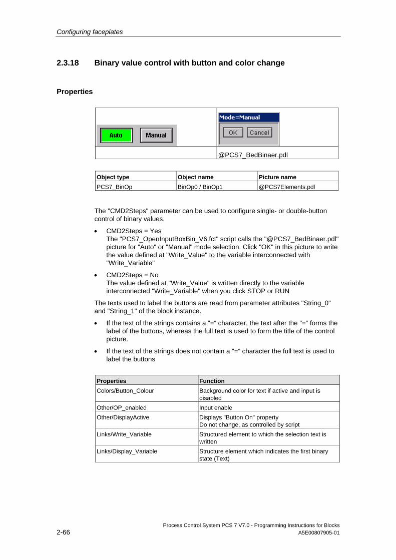
Configuring faceplates
Process Control System PCS 7 V7.0 - Programming Instructions for Blocks 2-66 A5E00807905-01
2.3.18 Binary value control with button and color change
Properties
@PCS7_BedBinaer.pdl
Object type Object name Picture name PCS7_BinOp BinOp0 / BinOp1 @PCS7Elements.pdl
The "CMD2Steps" parameter can be used to configure single- or double-button control of binary values.
• CMD2Steps = Yes The "PCS7_OpenInputBoxBin_V6.fct" script calls the "@PCS7_BedBinaer.pdl" picture for "Auto" or "Manual" mode selection. Click "OK" in this picture to write the value defined at "Write_Value" to the variable interconnected with "Write_Variable"
• CMD2Steps = No The value defined at "Write_Value" is written directly to the variable interconnected "Write_Variable" when you click STOP or RUN
The texts used to label the buttons are read from parameter attributes "String_0" and "String_1" of the block instance.
• If the text of the strings contains a "=“ character, the text after the "=“ forms the label of the buttons, whereas the full text is used to form the title of the control picture.
• If the text of the strings does not contain a "=“ character the full text is used to label the buttons
Properties Function Colors/Button_Colour Background color for text if active and input is
disabled Other/OP_enabled Input enable Other/DisplayActive Displays "Button On" property
Do not change, as controlled by script Links/Write_Variable Structured element to which the selection text is
written Links/Display_Variable Structure element which indicates the first binary
state (Text)
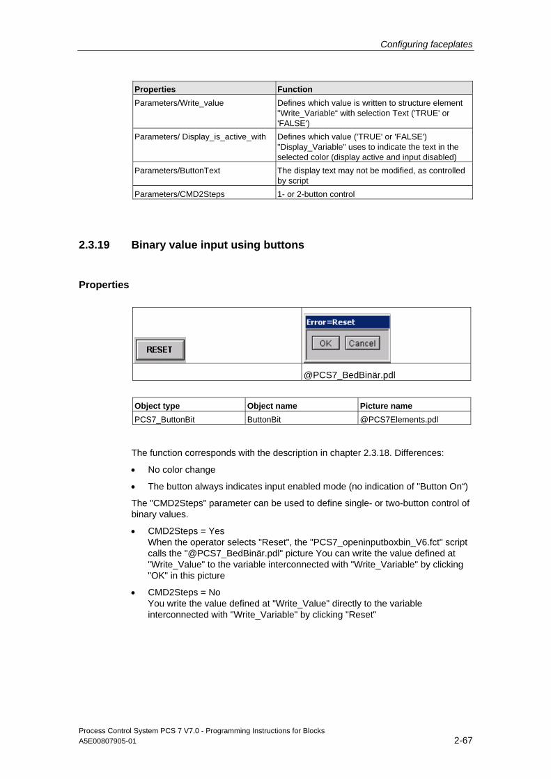
Configuring faceplates
Process Control System PCS 7 V7.0 - Programming Instructions for Blocks A5E00807905-01 2-67
Properties Function Parameters/Write_value Defines which value is written to structure element
"Write_Variable“ with selection Text ('TRUE' or 'FALSE')
Parameters/ Display_is_active_with Defines which value ('TRUE' or 'FALSE') "Display_Variable" uses to indicate the text in the selected color (display active and input disabled)
Parameters/ButtonText The display text may not be modified, as controlled by script
Parameters/CMD2Steps 1- or 2-button control
2.3.19 Binary value input using buttons
Properties
@PCS7_BedBinär.pdl
Object type Object name Picture name PCS7_ButtonBit ButtonBit @PCS7Elements.pdl
The function corresponds with the description in chapter 2.3.18. Differences:
• No color change
• The button always indicates input enabled mode (no indication of "Button On“)
The "CMD2Steps" parameter can be used to define single- or two-button control of binary values.
• CMD2Steps = Yes When the operator selects "Reset", the "PCS7_openinputboxbin_V6.fct" script calls the "@PCS7_BedBinär.pdl" picture You can write the value defined at "Write_Value" to the variable interconnected with "Write_Variable" by clicking "OK" in this picture
• CMD2Steps = No You write the value defined at "Write_Value" directly to the variable interconnected with "Write_Variable" by clicking "Reset"
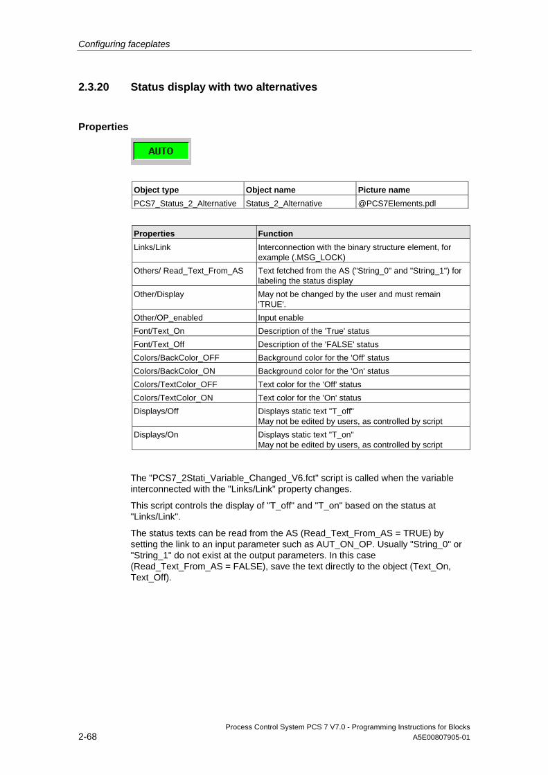
Configuring faceplates
Process Control System PCS 7 V7.0 - Programming Instructions for Blocks 2-68 A5E00807905-01
2.3.20 Status display with two alternatives
Properties
Object type Object name Picture name PCS7_Status_2_Alternative Status_2_Alternative @PCS7Elements.pdl
Properties Function Links/Link Interconnection with the binary structure element, for
example (.MSG_LOCK) Others/ Read_Text_From_AS Text fetched from the AS ("String_0" and "String_1") for
labeling the status display Other/Display May not be changed by the user and must remain
'TRUE'. Other/OP_enabled Input enable Font/Text_On Description of the 'True' status Font/Text_Off Description of the 'FALSE' status Colors/BackColor_OFF Background color for the 'Off' status Colors/BackColor_ON Background color for the 'On' status Colors/TextColor_OFF Text color for the 'Off' status Colors/TextColor_ON Text color for the 'On' status Displays/Off Displays static text "T_off"
May not be edited by users, as controlled by script Displays/On Displays static text "T_on"
May not be edited by users, as controlled by script
The "PCS7_2Stati_Variable_Changed_V6.fct" script is called when the variable interconnected with the "Links/Link" property changes.
This script controls the display of "T_off" and "T_on" based on the status at "Links/Link".
The status texts can be read from the AS (Read_Text_From_AS = TRUE) by setting the link to an input parameter such as AUT_ON_OP. Usually "String_0" or "String_1" do not exist at the output parameters. In this case (Read_Text_From_AS = FALSE), save the text directly to the object (Text_On, Text_Off).

Configuring faceplates
Process Control System PCS 7 V7.0 - Programming Instructions for Blocks A5E00807905-01 2-69
2.3.21 Status display with n alternatives
Properties
Object type Object name Picture name PCS7_Status_1_v_n Status_1_v_n @PCS7Elements.pdl
Properties Function Links/Link Interconnection with the binary structure element
(.MSG_LOCK) Others/ Read_Text_From_AS "Text_On" label for the status display, read from the AS
(String_1). Other/Display May not be modified by the user, as controlled by script Other/OP_enabled Input enable Font/Text_On Description of the 'True' status Colors/BackColor_ON Background color for the 'On' status Colors/TextColor_ON Text color for the 'On' status Masks/ Mask Value used to control visibility of the text box
For status displays with n options, the number of alternatives required determines the number of objects of the type Status_1_v_n to be arranged in an overlay stack.
The "PCS7_1vnStati_Variable_Changed_V6.fct" script is called when the variable which is interconnected with the "Links/Link" property changes.
You can define the value to be used to display the relevant object using the "Masks/Mask" property. This option is suitable for alternative control using INTEGER or REAL values, for example.
Set the value in "Mask" to 1 for all objects of an alternative control of multiple binary values. You can set the priority for all active binary values in the "Level“ property. WinCC supports levels 0 to 15, also in ascending order of priority.
Example Of two objects, one is assigned to level 4 and the other to level 5. Both objects are set visible and arranged in an overlay stack. The level 5 object is visible and the level 4 object remains hidden.
The status text can be read from the AS (Read_Text_From_AS = TRUE) by setting the link to an input parameter such as REV_ON. The output parameters usually do not contain "String_1". In this case (Read_Text_From_AS = FALSE), save the text directly to the object.
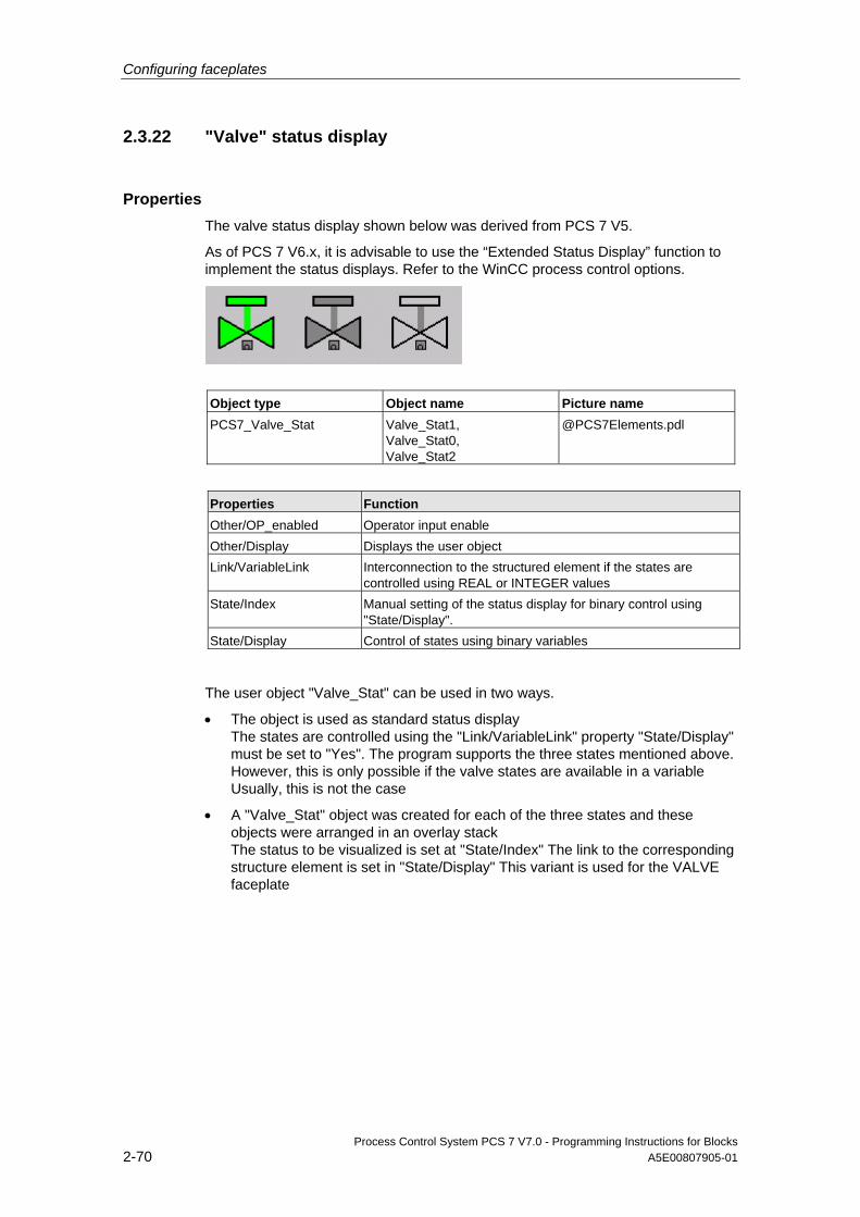
Configuring faceplates
Process Control System PCS 7 V7.0 - Programming Instructions for Blocks 2-70 A5E00807905-01
2.3.22 "Valve" status display
Properties The valve status display shown below was derived from PCS 7 V5.
As of PCS 7 V6.x, it is advisable to use the “Extended Status Display” function to implement the status displays. Refer to the WinCC process control options.
Object type Object name Picture name PCS7_Valve_Stat Valve_Stat1,
Valve_Stat0, Valve_Stat2
@PCS7Elements.pdl
Properties Function Other/OP_enabled Operator input enable Other/Display Displays the user object Link/VariableLink Interconnection to the structured element if the states are
controlled using REAL or INTEGER values State/Index Manual setting of the status display for binary control using
"State/Display". State/Display Control of states using binary variables
The user object "Valve_Stat" can be used in two ways.
• The object is used as standard status display The states are controlled using the "Link/VariableLink" property "State/Display" must be set to "Yes". The program supports the three states mentioned above. However, this is only possible if the valve states are available in a variable Usually, this is not the case
• A "Valve_Stat" object was created for each of the three states and these objects were arranged in an overlay stack The status to be visualized is set at "State/Index" The link to the corresponding structure element is set in "State/Display" This variant is used for the VALVE faceplate
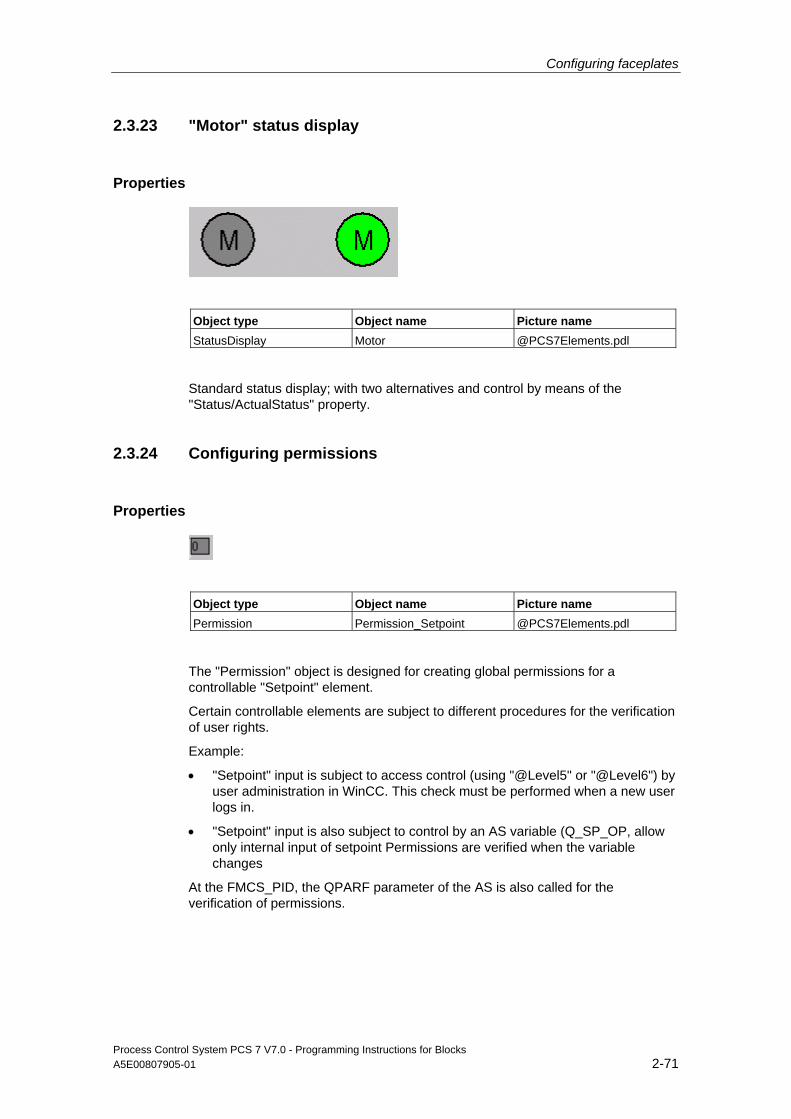
Configuring faceplates
Process Control System PCS 7 V7.0 - Programming Instructions for Blocks A5E00807905-01 2-71
2.3.23 "Motor" status display
Properties
Object type Object name Picture name StatusDisplay Motor @PCS7Elements.pdl
Standard status display; with two alternatives and control by means of the "Status/ActualStatus" property.
2.3.24 Configuring permissions
Properties
Object type Object name Picture name Permission Permission_Setpoint @PCS7Elements.pdl
The "Permission" object is designed for creating global permissions for a controllable "Setpoint" element.
Certain controllable elements are subject to different procedures for the verification of user rights.
Example:
• "Setpoint" input is subject to access control (using "@Level5" or "@Level6") by user administration in WinCC. This check must be performed when a new user logs in.
• "Setpoint" input is also subject to control by an AS variable (Q_SP_OP, allow only internal input of setpoint Permissions are verified when the variable changes
At the FMCS_PID, the QPARF parameter of the AS is also called for the verification of permissions.
Configuring faceplates
Process Control System PCS 7 V7.0 - Programming Instructions for Blocks 2-72 A5E00807905-01
Procedure To configure permissions:
1. Create a direct connection of "@Level5" or "@Level6", "Enable input" property to the "Permission" object, "Level_Source" property.
2. C script called when the "Level_Source" property changes:
BOOL bTag1 =!GetTagBitWait(".QPARF"); BOOL bTag2 =GetTagBitWait(".Q_SP_OP"); if (bTag1 && bTag2 && value) { SetPropBOOL(lpszPictureName,lpszObjectName,"Target_OP_Enable",TRUE); SetPropWord(lpszPictureName,lpszObjectName,"Target_BackgroundColor",CO_WHITE); } else { SetPropBOOL(lpszPictureName,lpszObjectName,"Target_Permission",FALSE); SetPropWord(lpszPictureName,lpszObjectName,"Target_BackgroundColor ",CO_LTGRAY); } SetPropBOOL(lpszPictureName,lpszObjectName,"Level_Target",value);
This script is called when a new user logs in or a picture has been selected.
The AS variables which are included in the verification of permissions must be checked at the same time. In this case, check the "QPARF" and "Q_SP_OP" variables.
The program sets the following values if all three criteria have been met:
- Property "TARGET_OP_ENABLE" = 'TRUE'
- The value at property "TARGET_BackgroundColor" is set to "white"
The value of property "Level_Source" is transferred to property "Level_Target".
"Level_Target“ is defined for the interconnection of the direct connections to further objects.
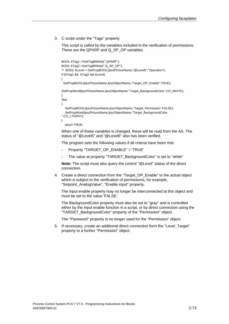
Configuring faceplates
Process Control System PCS 7 V7.0 - Programming Instructions for Blocks A5E00807905-01 2-73
3. C script under the "Tags" property
This script is called by the variables included in the verification of permissions. These are the QPARF and Q_SP_OP variables.
BOOL bTag1 =!GetTagBitWait(".QPARF"); BOOL bTag2 =GetTagBitWait(".Q_SP_OP"); ** BOOL bLevel = GetPropBOOL(lpszPictureName,"@Level5","Operation"); if (bTag1 && bTag2 && bLevel) { SetPropBOOL(lpszPictureName,lpszObjectName,"Target_OP_Enable",TRUE); SetPropWord(lpszPictureName,lpszObjectName,"Target_BackgroundColor",CO_WHITE); } else { SetPropBOOL(lpszPictureName,lpszObjectName,"Target_Permission",FALSE); SetPropWord(lpszPictureName,lpszObjectName,"Target_BackgroundColor ",CO_LTGRAY); } return TRUE;
When one of these variables is changed, these will be read from the AS. The status of "@Level5" and "@Level6" also has been verified.
The program sets the following values if all criteria have been met:
- Property "TARGET_OP_ENABLE" = 'TRUE'
- The value at property "TARGET_BackgroundColor" is set to "white"
Note: The script must also query the control "@Level" status of the direct connection.
4. Create a direct connection from the "Target_OP_Enable" to the actual object which is subject to the verification of permissions, for example, "Setpoint_AnalogValue", "Enable input" property.
The input enable property may no longer be interconnected at this object and must be set to the value 'FALSE'.
The BackgroundColor property must also be set to "gray" and is controlled either by the input enable function in a script, or by direct connection using the "TARGET_BackgroundColor" property of the "Permission" object.
The "Password" property is no longer used for the “Permission” object.
5. If necessary, create an additional direct connection form the "Level_Target" property to a further "Permission" object.
Configuring faceplates
Process Control System PCS 7 V7.0 - Programming Instructions for Blocks 2-74 A5E00807905-01
2.3.25 "OpenNextFaceplate" button
Calling the corresponding INTERLOK block in a motor or valve faceplate The "OpenNextFaceplate" is used in an open faceplate within a chart to call a further faceplate of an AS block.
A typical application is the call of the corresponding INTERLOK block in a motor or valve faceplate.
• The name of the block to be called is entered in the "blockname“ property
• The block type is entered in the usual format in the "Servername“ property, for example, "PCS7 INTERLOK Control“ for the INTERLOK block
• The variable name of the currently open faceplate is read when you click the button. The block name of the variable is then truncated and appended to the block name defined at "blockname"
• The structure element "#Comment“ exists in all blocks. It is also appended and checked for its existence in the file manager.
If it exists, the new variable name is written to the “tagname” property and the faceplate is called in the "PCS7_OpenGroupDisplay_V6“ script.
A script which is called when the "check_tag" property is changed also verifies the existence of the variable. The button is only enabled for input if the variable is available in the file manager.
In order to ensure proper execution of the script in the "check_tag“ property when a screen is selected a valid structure element whose text is different to the default text of the property must be interconnected with the "check_tag“ property. This setting allows the program to detect changes at the property. The structure element "#Comment“ which exists in all blocks is again used for this operation.
Configuring faceplates
Process Control System PCS 7 V7.0 - Programming Instructions for Blocks A5E00807905-01 2-75
Using several INTERLOK blocks for a motor or valve Another commonly used application lies in the implementation of multiple INTERLOK blocks for a motor or valve.
The same object can be installed in the INTERLOK block for this application. Enter the value 1 at the "blockname" property for the cascaded call.
If the AS block name of the currently called faceplate variable (tagname) is not appended a number, for example, its name is "L“, the AS block named "L1“ is called from the same chart in the next step, provided the corresponding variable name exists in the file manager.
If the AS block name of the currently called variable name of the faceplate is "L1“, a call of "L2“ is expected in the next step, etc.
This method basically allows the call of any number of INTERLOK blocks.
Configuration rule for this scenario:
• An "OpenNextFaceplate" button with the block name "LOCK" is installed in a VALVE faceplate
• An "OpenNextFaceplate button with the block name "1" is installed in the INTERLOK block
• INTERLOK blocks called by the faceplate type "VALVE" must be named "LOCK", "LOCK1", "LOCK2" etc. when using the method described above
Access control The "OpenNextFaceplate" object is also assigned the "Processcontrolling_backup“ and "Higherprocesscontrolling_backup“ properties for setting permissions for the faceplate to be called. The usual default settings are here the permission levels 5 and 6. You can transfer the permissions entered in the source symbol to the "OpenNextFaceplate" object using the direct connections of "@Level5" and "@Level6".
Direct connections @Level5/Permission/Change OpenNextFaceplate/Processcontrolling
@Level6/Permission/Change OpenNextFaceplate/HigherProcesscontrolling
Configuring faceplates
Process Control System PCS 7 V7.0 - Programming Instructions for Blocks 2-76 A5E00807905-01
2.3.26 "Disable / Enable messages" button
Overview objects The "Disable/enable messages" function is implemented in the overview using this
button: .
The button is only visible to operators assigned the permission level defined at the block icon property "Processcontrolling_backup".
Properties Object type Object name Picture name Button Button17 @PCS7Elements.pdl
The message disable/enable button corresponds with the button of the standard button set "@Buttons11.pdl", however, with a different script for instance-specific disabling/enabling of messages.
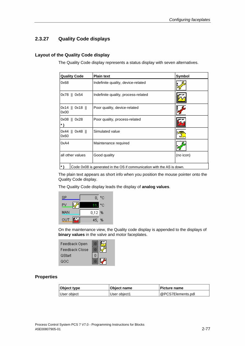
Configuring faceplates
Process Control System PCS 7 V7.0 - Programming Instructions for Blocks A5E00807905-01 2-77
2.3.27 Quality Code displays
Layout of the Quality Code display The Quality Code display represents a status display with seven alternatives.
Quality Code Plain text Symbol
0x68 Indefinite quality, device-related
0x78 || 0x54 Indefinite quality, process-related
0x14 || 0x18 || 0x00
Poor quality, device-related
0x08 || 0x28 * )
Poor quality, process-related
0x44 || 0x48 || 0x60
Simulated value
0xA4 Maintenance required
all other values Good quality (no icon)
* ) Code 0x08 is generated in the OS if communication with the AS is down.
The plain text appears as short info when you position the mouse pointer onto the Quality Code display.
The Quality Code display leads the display of analog values.
On the maintenance view, the Quality code display is appended to the displays of binary values in the valve and motor faceplates.
Properties Object type Object name Picture name User object User object1 @PCS7Elements.pdl
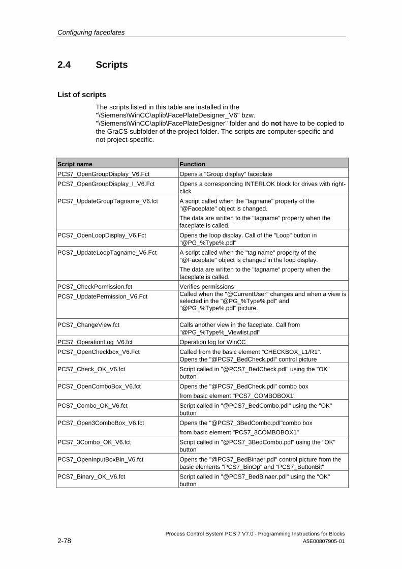
Configuring faceplates
Process Control System PCS 7 V7.0 - Programming Instructions for Blocks 2-78 A5E00807905-01
2.4 Scripts
List of scripts The scripts listed in this table are installed in the "\Siemens\WinCC\aplib\FacePlateDesigner_V6" bzw. "\Siemens\WinCC\aplib\FacePlateDesigner" folder and do not have to be copied to the GraCS subfolder of the project folder. The scripts are computer-specific and not project-specific.
Script name Function PCS7_OpenGroupDisplay_V6.Fct Opens a "Group display" faceplate PCS7_OpenGroupDisplay_I_V6.Fct Opens a corresponding INTERLOK block for drives with right-
click PCS7_UpdateGroupTagname_V6.fct A script called when the "tagname" property of the
"@Faceplate" object is changed. The data are written to the "tagname“ property when the faceplate is called.
PCS7_OpenLoopDisplay_V6.Fct Opens the loop display. Call of the "Loop" button in "@PG_%Type%.pdl"
PCS7_UpdateLoopTagname_V6.Fct A script called when the "tag name" property of the "@Faceplate" object is changed in the loop display. The data are written to the "tagname“ property when the faceplate is called.
PCS7_CheckPermission.fct Verifies permissions PCS7_UpdatePermission_V6.Fct Called when the "@CurrentUser" changes and when a view is
selected in the "@PG_%Type%.pdl" and "@PG_%Type%.pdl" picture.
PCS7_ChangeView.fct Calls another view in the faceplate. Call from "@PG_%Type%_Viewlist.pdl"
PCS7_OperationLog_V6.fct Operation log for WinCC PCS7_OpenCheckbox_V6.Fct Called from the basic element "CHECKBOX_L1/R1".
Opens the "@PCS7_BedCheck.pdl" control picture PCS7_Check_OK_V6.fct Script called in "@PCS7_BedCheck.pdl" using the "OK"
button PCS7_OpenComboBox_V6.fct Opens the "@PCS7_BedCheck.pdl" combo box
from basic element "PCS7_COMBOBOX1" PCS7_Combo_OK_V6.fct Script called in "@PCS7_BedCombo.pdl" using the "OK"
button PCS7_Open3ComboBox_V6.fct Opens the "@PCS7_3BedCombo.pdl"combo box
from basic element "PCS7_3COMBOBOX1" PCS7_3Combo_OK_V6.fct Script called in "@PCS7_3BedCombo.pdl" using the "OK"
button PCS7_OpenInputBoxBin_V6.fct Opens the "@PCS7_BedBinaer.pdl" control picture from the
basic elements "PCS7_BinOp" and "PCS7_ButtonBit" PCS7_Binary_OK_V6.fct Script called in "@PCS7_BedBinaer.pdl" using the "OK"
button
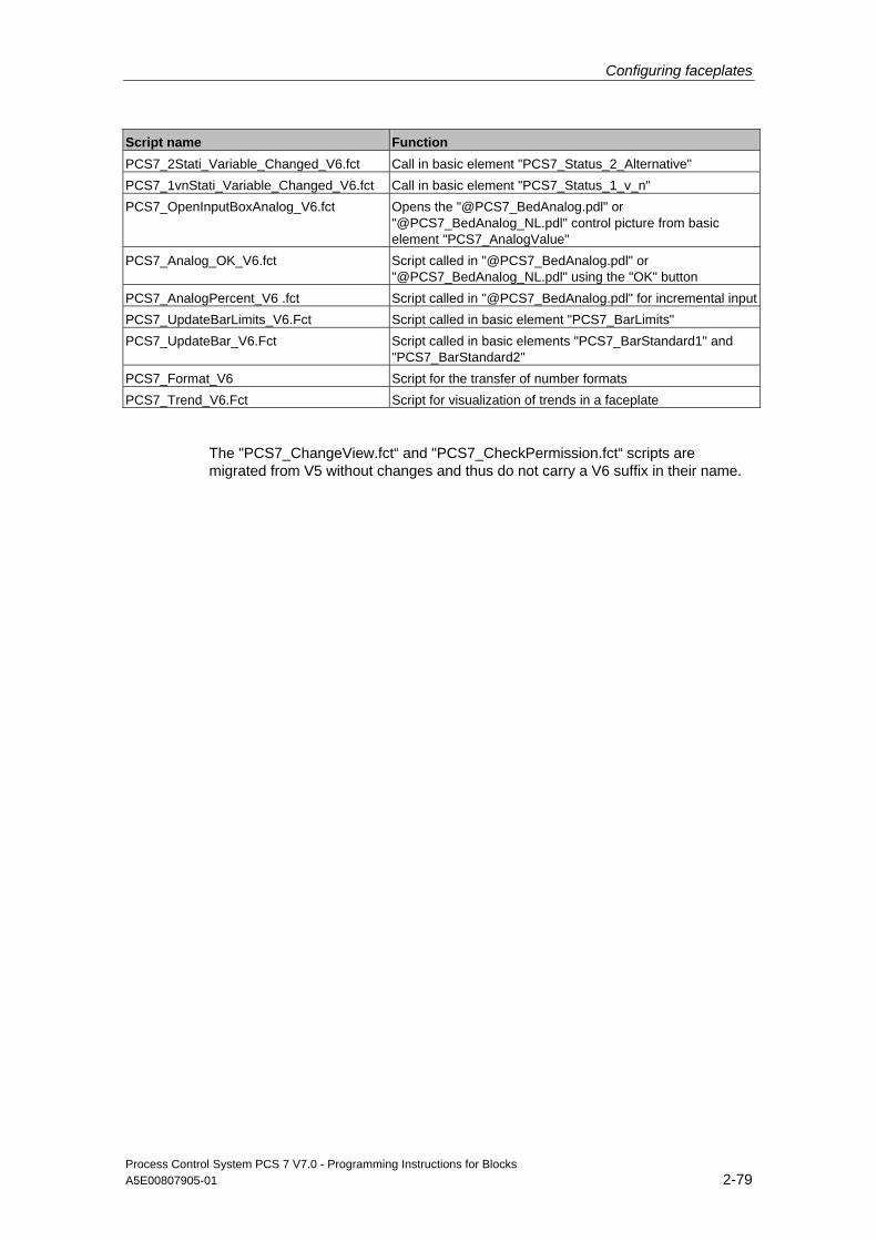
Configuring faceplates
Process Control System PCS 7 V7.0 - Programming Instructions for Blocks A5E00807905-01 2-79
Script name Function PCS7_2Stati_Variable_Changed_V6.fct Call in basic element "PCS7_Status_2_Alternative" PCS7_1vnStati_Variable_Changed_V6.fct Call in basic element "PCS7_Status_1_v_n" PCS7_OpenInputBoxAnalog_V6.fct Opens the "@PCS7_BedAnalog.pdl" or
"@PCS7_BedAnalog_NL.pdl" control picture from basic element "PCS7_AnalogValue"
PCS7_Analog_OK_V6.fct Script called in "@PCS7_BedAnalog.pdl" or "@PCS7_BedAnalog_NL.pdl" using the "OK" button
PCS7_AnalogPercent_V6 .fct Script called in "@PCS7_BedAnalog.pdl" for incremental inputPCS7_UpdateBarLimits_V6.Fct Script called in basic element "PCS7_BarLimits" PCS7_UpdateBar_V6.Fct Script called in basic elements "PCS7_BarStandard1" and
"PCS7_BarStandard2" PCS7_Format_V6 Script for the transfer of number formats PCS7_Trend_V6.Fct Script for visualization of trends in a faceplate
The "PCS7_ChangeView.fct“ and "PCS7_CheckPermission.fct“ scripts are migrated from V5 without changes and thus do not carry a V6 suffix in their name.
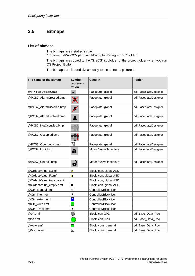
Configuring faceplates
Process Control System PCS 7 V7.0 - Programming Instructions for Blocks 2-80 A5E00807905-01
2.5 Bitmaps
List of bitmaps The bitmaps are installed in the "...\Siemens\WinCC\options\pdl\FaceplateDesigner_V6" folder. The bitmaps are copied to the "GraCS" subfolder of the project folder when you run OS Project Editor. The bitmaps are loaded dynamically to the selected pictures.
File name of the bitmap Symbol represen-tation
Used in Folder
@FP_PopUpIcon.bmp Faceplate, global pdl\FaceplateDesigner
@PCS7_AlarmCrossed.bmp
Faceplate, global pdl\FaceplateDesigner
@PCS7_AlarmDisabled.bmp
Faceplate, global pdl\FaceplateDesigner
@PCS7_AlarmEnabled.bmp
Faceplate, global pdl\FaceplateDesigner
@PCS7_NotOccupied.bmp
Faceplate, global pdl\FaceplateDesigner
@PCS7_Occupied.bmp
Faceplate, global pdl\FaceplateDesigner
@PCS7_OpenLoop.bmp Faceplate, global pdl\FaceplateDesigner
@PCS7_Lock.bmp
Motor / valve faceplate pdl\FaceplateDesigner
@PCS7_UnLock.bmp
Motor / valve faceplate pdl\FaceplateDesigner
@CollectValue_S.emf S Block icon, global ASD @CollectValue_F.emf F Block icon, global ASD @CollectValue_transparent. Block icon, global ASD @CollectValue_empty.emf Block icon, global ASD @Ctrl_Manual.emf M Controller/Block icon @Ctrl_intern.emf I Controller/Block icon @Ctrl_extern.emf E Controller/Block icon @Ctrl_Auto.emf A Controller/Block icon @Ctrl_Track.emf T Controller/Block icon @off.emf Block icon OPD pdl\Base_Data_Poo
@on.emf
Block icon OPD pdl\Base_Data_Poo
@Auto.emf A Block icons, general pdl\Base_Data_Poo @Manual.emf M Block icons, general pdl\Base_Data_Poo
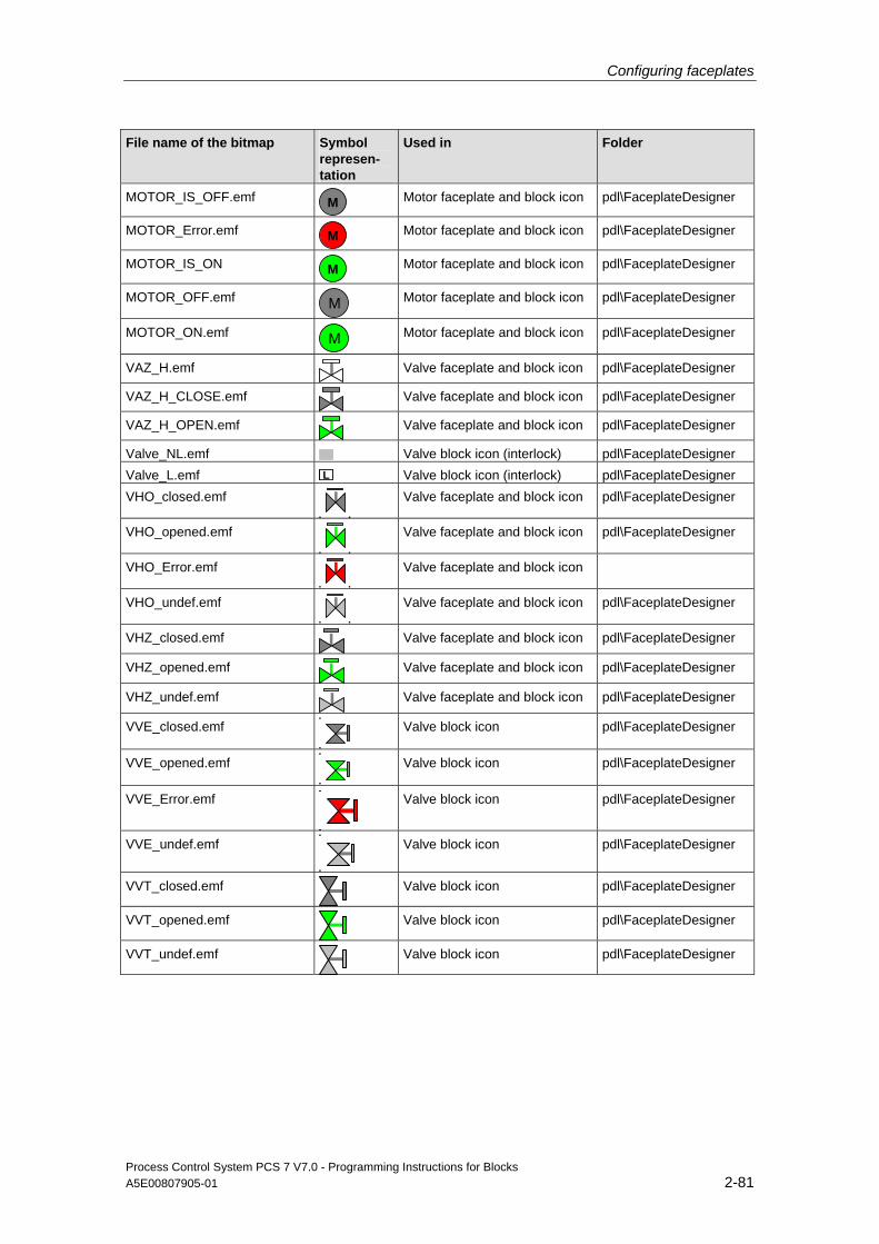
Configuring faceplates
Process Control System PCS 7 V7.0 - Programming Instructions for Blocks A5E00807905-01 2-81
File name of the bitmap Symbol represen-tation
Used in Folder
MOTOR_IS_OFF.emf M
Motor faceplate and block icon pdl\FaceplateDesigner
MOTOR_Error.emf M
Motor faceplate and block icon pdl\FaceplateDesigner
MOTOR_IS_ON M
Motor faceplate and block icon pdl\FaceplateDesigner
MOTOR_OFF.emf M
Motor faceplate and block icon pdl\FaceplateDesigner
MOTOR_ON.emf M
Motor faceplate and block icon pdl\FaceplateDesigner
VAZ_H.emf
Valve faceplate and block icon pdl\FaceplateDesigner
VAZ_H_CLOSE.emf
Valve faceplate and block icon pdl\FaceplateDesigner
VAZ_H_OPEN.emf
Valve faceplate and block icon pdl\FaceplateDesigner
Valve_NL.emf Valve block icon (interlock) pdl\FaceplateDesigner Valve_L.emf ML Valve block icon (interlock) pdl\FaceplateDesigner VHO_closed.emf
Valve faceplate and block icon pdl\FaceplateDesigner
VHO_opened.emf
Valve faceplate and block icon pdl\FaceplateDesigner
VHO_Error.emf
Valve faceplate and block icon
VHO_undef.emf
Valve faceplate and block icon pdl\FaceplateDesigner
VHZ_closed.emf
Valve faceplate and block icon pdl\FaceplateDesigner
VHZ_opened.emf
Valve faceplate and block icon pdl\FaceplateDesigner
VHZ_undef.emf
Valve faceplate and block icon pdl\FaceplateDesigner
VVE_closed.emf
Valve block icon pdl\FaceplateDesigner
VVE_opened.emf
Valve block icon pdl\FaceplateDesigner
VVE_Error.emf
Valve block icon pdl\FaceplateDesigner
VVE_undef.emf
Valve block icon pdl\FaceplateDesigner
VVT_closed.emf
Valve block icon pdl\FaceplateDesigner
VVT_opened.emf
Valve block icon pdl\FaceplateDesigner
VVT_undef.emf
Valve block icon pdl\FaceplateDesigner
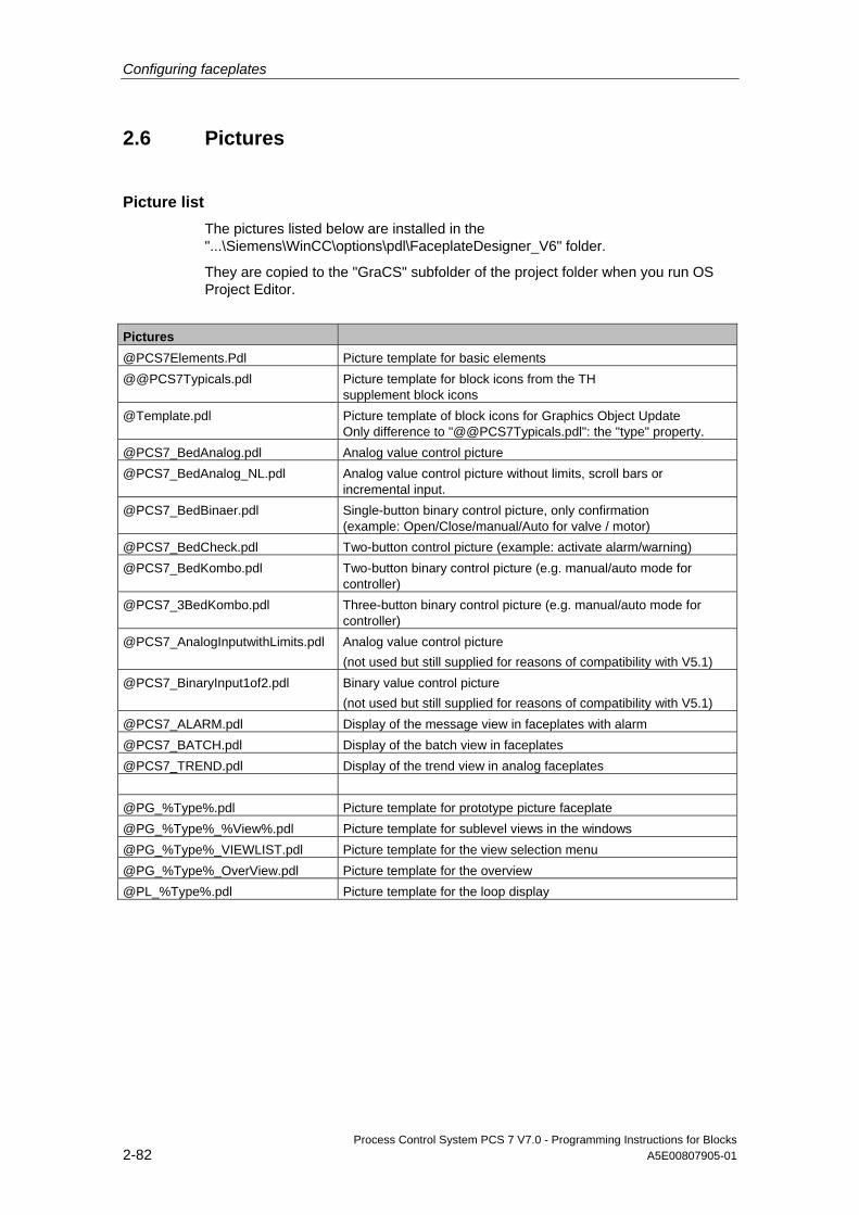
Configuring faceplates
Process Control System PCS 7 V7.0 - Programming Instructions for Blocks 2-82 A5E00807905-01
2.6 Pictures
Picture list The pictures listed below are installed in the "...\Siemens\WinCC\options\pdl\FaceplateDesigner_V6" folder.
They are copied to the "GraCS" subfolder of the project folder when you run OS Project Editor.
Pictures @PCS7Elements.Pdl Picture template for basic elements @@PCS7Typicals.pdl Picture template for block icons from the TH
supplement block icons @Template.pdl Picture template of block icons for Graphics Object Update
Only difference to "@@PCS7Typicals.pdl": the "type" property. @PCS7_BedAnalog.pdl Analog value control picture @PCS7_BedAnalog_NL.pdl Analog value control picture without limits, scroll bars or
incremental input. @PCS7_BedBinaer.pdl Single-button binary control picture, only confirmation
(example: Open/Close/manual/Auto for valve / motor) @PCS7_BedCheck.pdl Two-button control picture (example: activate alarm/warning) @PCS7_BedKombo.pdl Two-button binary control picture (e.g. manual/auto mode for
controller) @PCS7_3BedKombo.pdl Three-button binary control picture (e.g. manual/auto mode for
controller) @PCS7_AnalogInputwithLimits.pdl Analog value control picture
(not used but still supplied for reasons of compatibility with V5.1) @PCS7_BinaryInput1of2.pdl Binary value control picture
(not used but still supplied for reasons of compatibility with V5.1) @PCS7_ALARM.pdl Display of the message view in faceplates with alarm @PCS7_BATCH.pdl Display of the batch view in faceplates @PCS7_TREND.pdl Display of the trend view in analog faceplates @PG_%Type%.pdl Picture template for prototype picture faceplate @PG_%Type%_%View%.pdl Picture template for sublevel views in the windows @PG_%Type%_VIEWLIST.pdl Picture template for the view selection menu @PG_%Type%_OverView.pdl Picture template for the overview @PL_%Type%.pdl Picture template for the loop display
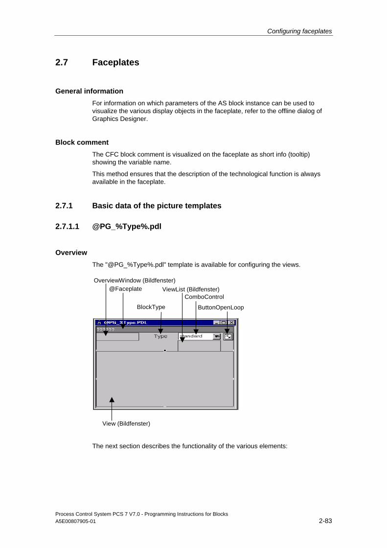
Configuring faceplates
Process Control System PCS 7 V7.0 - Programming Instructions for Blocks A5E00807905-01 2-83
2.7 Faceplates
General information For information on which parameters of the AS block instance can be used to visualize the various display objects in the faceplate, refer to the offline dialog of Graphics Designer.
Block comment The CFC block comment is visualized on the faceplate as short info (tooltip) showing the variable name.
This method ensures that the description of the technological function is always available in the faceplate.
2.7.1 Basic data of the picture templates
2.7.1.1 @PG_%Type%.pdl
Overview The "@PG_%Type%.pdl" template is available for configuring the views.
View (Bildfenster)
OverviewWindow (Bildfenster)@Faceplate ViewList (Bildfenster)
BlockType
ComboControl
ButtonOpenLoop
The next section describes the functionality of the various elements:

Configuring faceplates
Process Control System PCS 7 V7.0 - Programming Instructions for Blocks 2-84 A5E00807905-01
OverviewWindow Window used to visualize alarm and batch states, and for instance-specific message acknowledgment and enabling messages of the faceplate. A group display is usually shown here. If the faceplate is used for a multiple instance block it may also show several group displays. The display is defined in the configuration of the "@PG_<Type>_Overview.pdl“ picture. The same picture is shown in the loop view of the faceplate. Used to visualize the block instance or variable of the calling object. It is also used to store additional faceplate information such as FirstView, the name of the batch variable or CurrentUser. User object with I/O field, for storing data of the trend function "Trendpage". This object is hidden in online mode. Name of the faceplate type. This type name forms part of the name of all views belonging to the faceplate. This object is hidden in online mode.
ViewList Window used to visualize and select existing views.
ComboControl Selection and display element for the various views. The element always shows the name of the active view.
ButtonOpenLoop Object for selecting the loop picture. Faceplate Designer automatically hides this object if generation or update of the loop view is not selected.
View Window used to display the various faceplate views.
OperationWindow Window used to display analog value input.
ComboWindow Window used to display binary value input.
Configuring faceplates
Process Control System PCS 7 V7.0 - Programming Instructions for Blocks A5E00807905-01 2-85
2.7.1.2 @PG_%TYPE%
@PG_%TYPE% picture object Geometry/Pos X=0, y = 0 Geometry/Dimensions Width = 320, Height = 260
"View" window Geometry/Pos X=1, y = 47 Geometry/Dimensions Width = 320, Height = 214
User object @Faceplate Elements of the "@Faceplate" user object: Property in the user object
Element Type Default
Geometry/Pos X=0, y = 0
Geometry/Dimensions
Breite = 320, Höhe = 20
Tagname Tagname Stat.Text None Tag Tag Stat.Text Text = MKZ FirstView FirstView I/O box Output value is set by
Faceplate Designer CurrentUser CurrentUser I/O box Output value = interconnection
to internal variable @Current User
BName VarBatchname I/O box Output value = .BA_NA BATCH_ID VarBatchID I/O box Output value = .BA_ID STEP_NO VarBatch
Stepnumber I/O box Output value = .STEP_NO
STEP_N1 VarBatch Stepnumber_N1
I/O box Output value = .STEP_N1
Areaname Areaname I/O box Output value = .#areaname Processcontrolling_backup
POP I/O box Permission = Processcontrolling
HigherProcess controlling_backup
HIPOP I/O box Permission = Higher Processcontrolling
MULTI_INSTANCE HIPOP.Hidden Input
I/O box True = MultiInstanceFaceplate
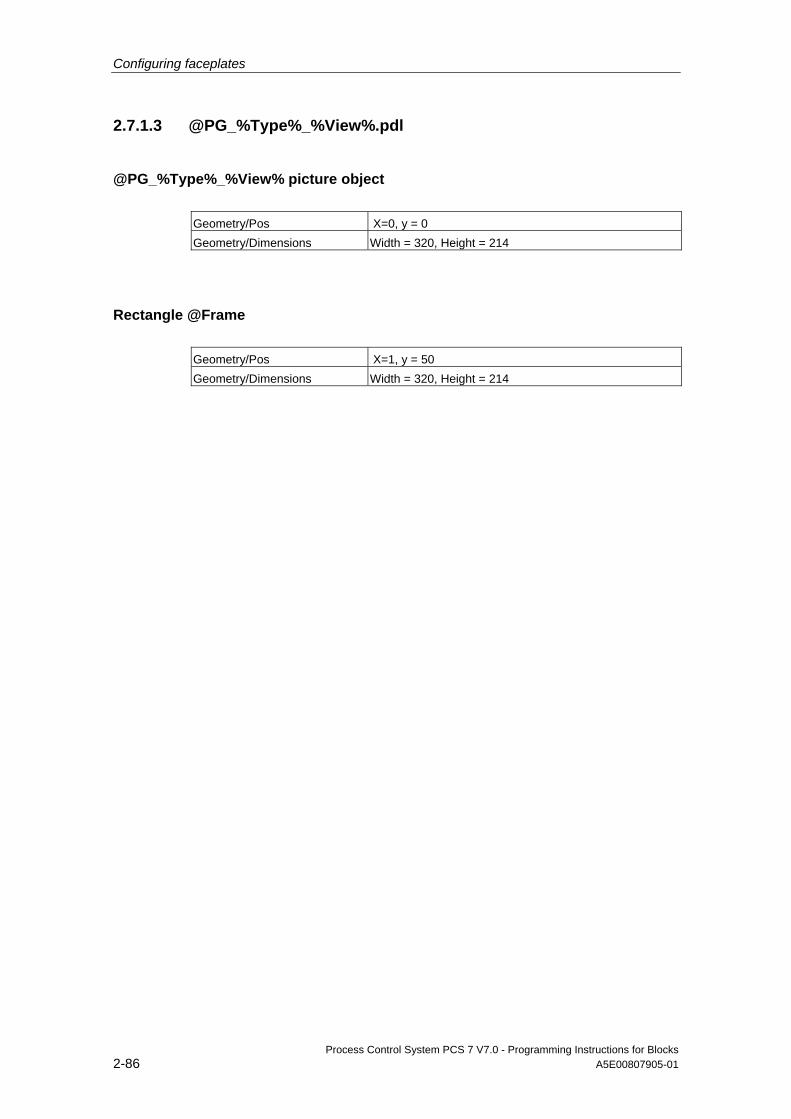
Configuring faceplates
Process Control System PCS 7 V7.0 - Programming Instructions for Blocks 2-86 A5E00807905-01
2.7.1.3 @PG_%Type%_%View%.pdl
@PG_%Type%_%View% picture object Geometry/Pos X=0, y = 0 Geometry/Dimensions Width = 320, Height = 214
Rectangle @Frame Geometry/Pos X=1, y = 50 Geometry/Dimensions Width = 320, Height = 214
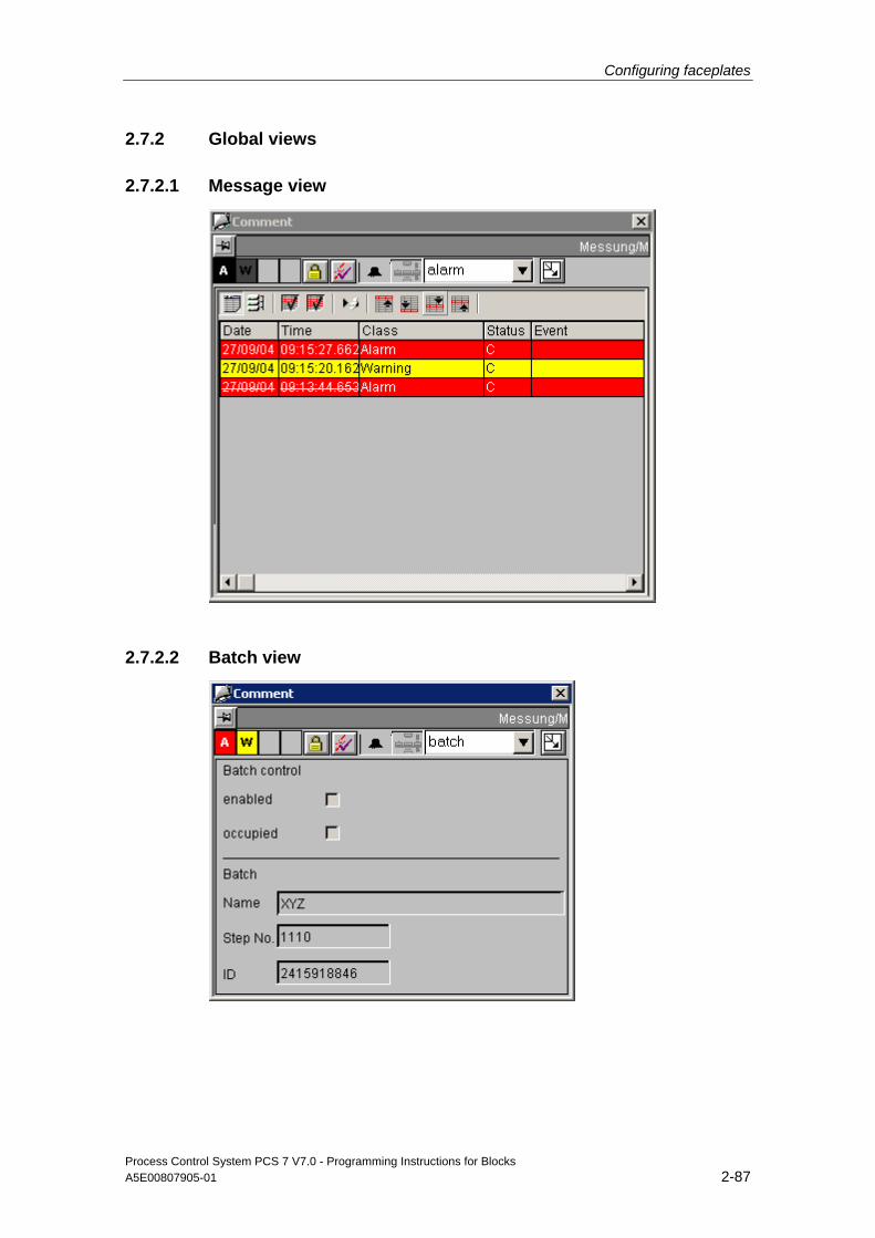
Configuring faceplates
Process Control System PCS 7 V7.0 - Programming Instructions for Blocks A5E00807905-01 2-87
2.7.2 Global views
2.7.2.1 Message view
2.7.2.2 Batch view
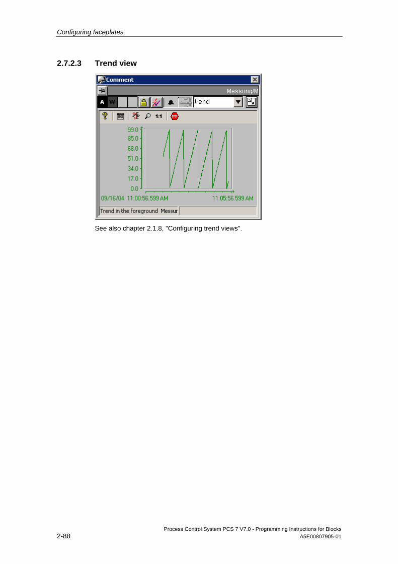
Configuring faceplates
Process Control System PCS 7 V7.0 - Programming Instructions for Blocks 2-88 A5E00807905-01
2.7.2.3 Trend view
See also chapter 2.1.8, "Configuring trend views".
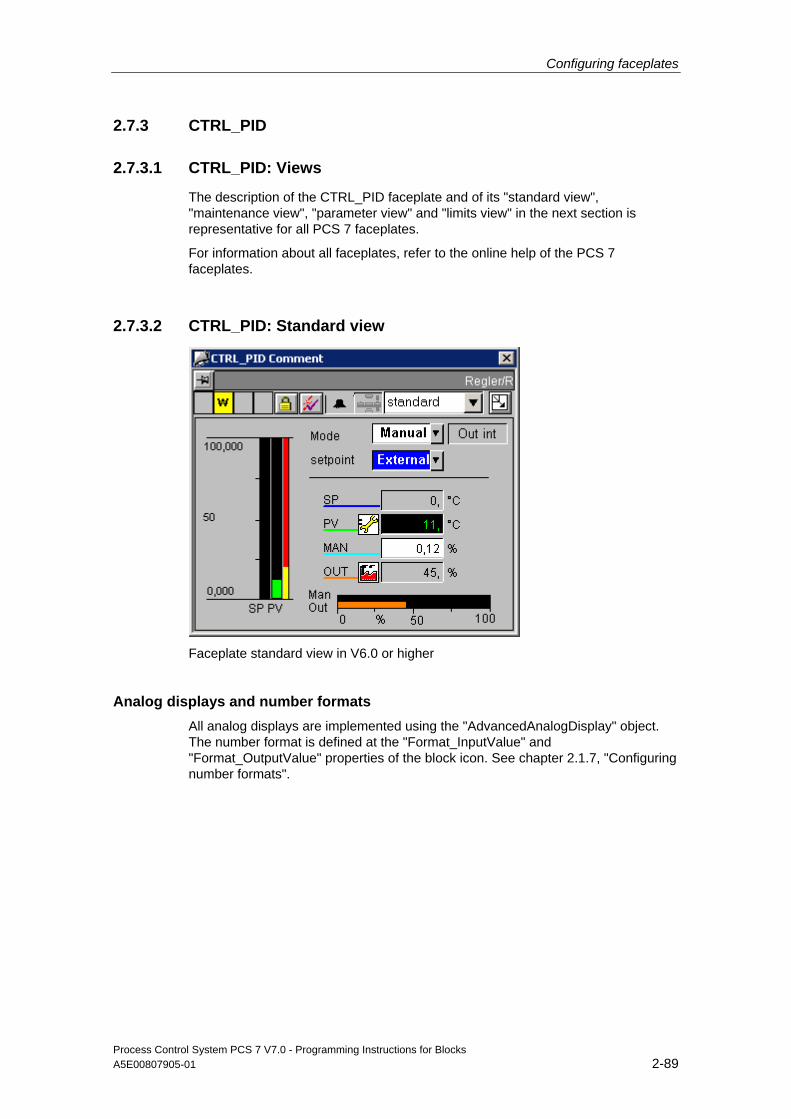
Configuring faceplates
Process Control System PCS 7 V7.0 - Programming Instructions for Blocks A5E00807905-01 2-89
2.7.3 CTRL_PID
2.7.3.1 CTRL_PID: Views
The description of the CTRL_PID faceplate and of its "standard view", "maintenance view", "parameter view" and "limits view" in the next section is representative for all PCS 7 faceplates.
For information about all faceplates, refer to the online help of the PCS 7 faceplates.
2.7.3.2 CTRL_PID: Standard view
Faceplate standard view in V6.0 or higher
Analog displays and number formats All analog displays are implemented using the "AdvancedAnalogDisplay" object. The number format is defined at the "Format_InputValue" and "Format_OutputValue" properties of the block icon. See chapter 2.1.7, "Configuring number formats".

Configuring faceplates
Process Control System PCS 7 V7.0 - Programming Instructions for Blocks 2-90 A5E00807905-01
Access control The view features two permission objects for the input of setpoints and manipulated values, as permissions for these variables depend on different factors:
• "Permission_Setpoint"
• "Permission_Manual"
See also chapter 2.3.24, Basic elements, Permission Object.
In addition to the WinCC user rights, the permission objects evaluate the parameters listed below:
Permission object Parameters "Permission_Setpoint" "Q_SP_OP = TRUE" "Permission_Manual" "QLMNOP = TRUE"
Using PID Tuner and tuning Operate the PID Tuner in the parameter view (Tuning on/off).
A combo box is output above the operating mode combo box „Manual/Auto“ in the standard view when you enable tuning in the parameter view. Tuning is also disabled again using this combo box in the standard view. All other operations of the controller are locked when "Tuning On“ is set.
Sequence and positioning of direct connections at the control objects @Level5 -> Operator input enable Manual_COMBOBOX -> Operator input enable External_COMBOBOX -> Operator input enable Permission_Setpoint -> Level_Source -> Level_Target Permission_Manual -> Level_Source Permission_Setpoint -> Target_OP_enable Setpoint_AnalogValue -> Operator input enable Permission_Manual -> Target_OP_enable Manual_AnalogValue -> Operator input enable Format -> Format_InputValue Setpoint_AnalogValue -> Format ProcessValue_AnalogValue -> Format Format -> Format_OutputValue Manual_AnalogValue -> Format Output_AnalogValue -> Format
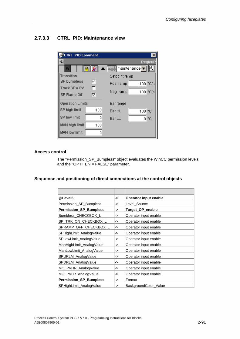
Configuring faceplates
Process Control System PCS 7 V7.0 - Programming Instructions for Blocks A5E00807905-01 2-91
2.7.3.3 CTRL_PID: Maintenance view
Access control The "Permission_SP_Bumpless“ object evaluates the WinCC permission levels and the "OPTI_EN = FALSE“ parameter.
Sequence and positioning of direct connections at the control objects @Level6 -> Operator input enable Permission_SP_Bumpless -> Level_Source Permission_SP_Bumpless -> Target_OP_enable Bumbless_CHECKBOX_L -> Operator input enable SP_TRK_ON_CHECKBOX_L -> Operator input enable SPRAMP_OFF_CHECKBOX_L -> Operator input enable SPHighLimit_AnalogValue -> Operator input enable SPLowLimit_AnalogValue -> Operator input enable ManHighLimit_AnalogValue -> Operator input enable ManLowLimit_AnalogValue -> Operator input enable SPURLM_AnalogValue -> Operator input enable SPDRLM_AnalogValue -> Operator input enable MO_PVHR_AnalogValue -> Operator input enable MO_PVLR_AnalogValue -> Operator input enable Permission_SP_Bumpless -> Format SPHighLimit_AnalogValue -> BackgroundColor_Value
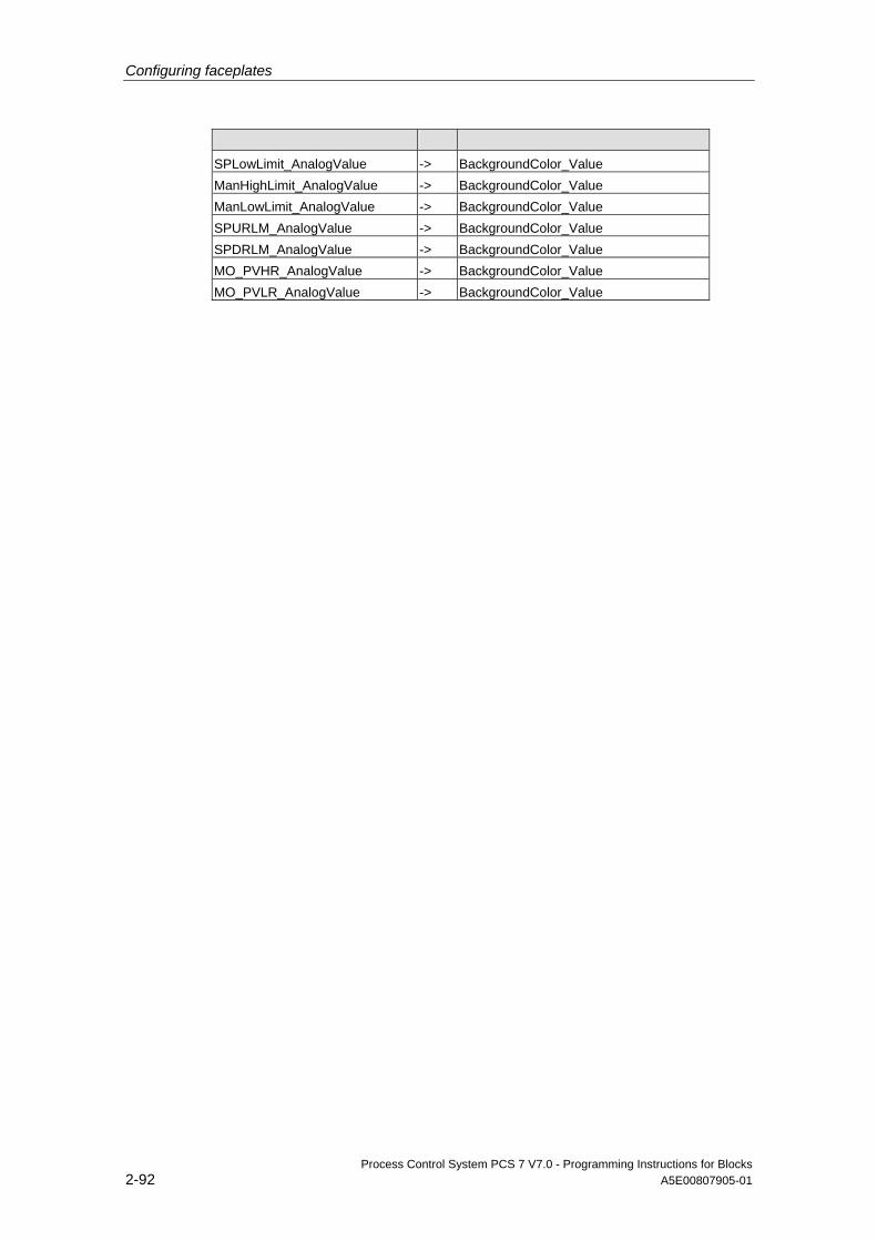
Configuring faceplates
Process Control System PCS 7 V7.0 - Programming Instructions for Blocks 2-92 A5E00807905-01
SPLowLimit_AnalogValue -> BackgroundColor_Value ManHighLimit_AnalogValue -> BackgroundColor_Value ManLowLimit_AnalogValue -> BackgroundColor_Value SPURLM_AnalogValue -> BackgroundColor_Value SPDRLM_AnalogValue -> BackgroundColor_Value MO_PVHR_AnalogValue -> BackgroundColor_Value MO_PVLR_AnalogValue -> BackgroundColor_Value
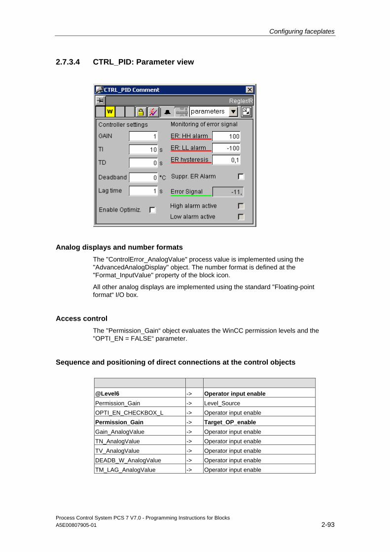
Configuring faceplates
Process Control System PCS 7 V7.0 - Programming Instructions for Blocks A5E00807905-01 2-93
2.7.3.4 CTRL_PID: Parameter view
Analog displays and number formats The "ControlError_AnalogValue" process value is implemented using the "AdvancedAnalogDisplay" object. The number format is defined at the "Format_InputValue" property of the block icon.
All other analog displays are implemented using the standard "Floating-point format“ I/O box.
Access control The "Permission_Gain“ object evaluates the WinCC permission levels and the "OPTI_EN = FALSE“ parameter.
Sequence and positioning of direct connections at the control objects @Level6 -> Operator input enable Permission_Gain -> Level_Source OPTI_EN_CHECKBOX_L -> Operator input enable Permission_Gain -> Target_OP_enable Gain_AnalogValue -> Operator input enable TN_AnalogValue -> Operator input enable TV_AnalogValue -> Operator input enable DEADB_W_AnalogValue -> Operator input enable TM_LAG_AnalogValue -> Operator input enable

Configuring faceplates
Process Control System PCS 7 V7.0 - Programming Instructions for Blocks 2-94 A5E00807905-01
ERH_ALM_AnalogValue -> Operator input enable ERL_ALM_AnalogValue -> Operator input enable ER_HYS_AnalogValue3 -> Operator input enable M_SUP_ER_CHECKBOX_L -> Operator input enable Permission_Gain -> Target_BackgroundColor Gain_AnalogValue -> BackgroundColor_Value TN_AnalogValue -> BackgroundColor_Value TV_AnalogValue -> BackgroundColor_Value DEADB_W_AnalogValue -> BackgroundColor_Value TM_LAG_AnalogValue -> BackgroundColor_Value ERH_ALM_AnalogValue -> BackgroundColor_Value ERL_ALM_AnalogValue -> BackgroundColor_Value ER_HYS_AnalogValue3 -> BackgroundColor_Value Format -> Format_InputValue ControlError_AnalogValue -> Format
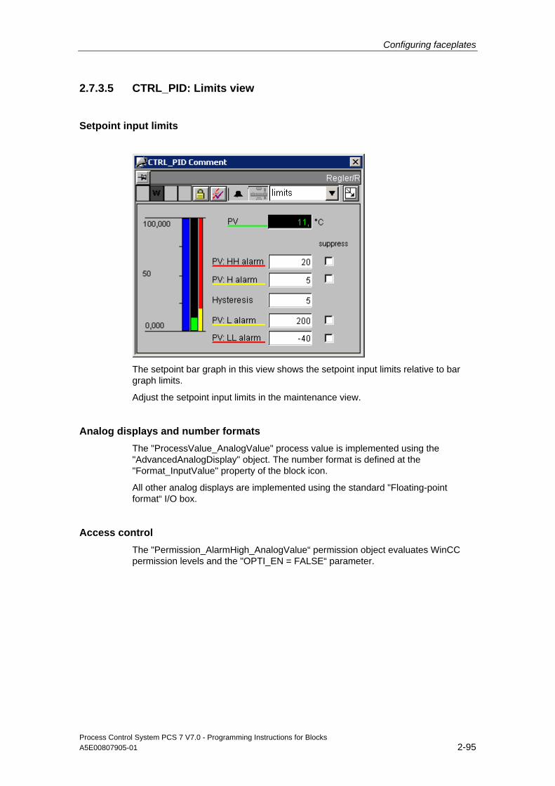
Configuring faceplates
Process Control System PCS 7 V7.0 - Programming Instructions for Blocks A5E00807905-01 2-95
2.7.3.5 CTRL_PID: Limits view
Setpoint input limits
The setpoint bar graph in this view shows the setpoint input limits relative to bar graph limits.
Adjust the setpoint input limits in the maintenance view.
Analog displays and number formats The "ProcessValue_AnalogValue" process value is implemented using the "AdvancedAnalogDisplay" object. The number format is defined at the "Format_InputValue" property of the block icon.
All other analog displays are implemented using the standard "Floating-point format“ I/O box.
Access control The "Permission_AlarmHigh_AnalogValue“ permission object evaluates WinCC permission levels and the "OPTI_EN = FALSE“ parameter.

Configuring faceplates
Process Control System PCS 7 V7.0 - Programming Instructions for Blocks 2-96 A5E00807905-01
Sequence and positioning of direct connections at the control objects @Level6 Operator input enable Permission_AlarmHigh_AnalogValue
-> Level_Source
Permission_AlarmHigh_AnalogValue
-> Target_OP_enable
AlarmHigh_AnalogValue -> Operator input enable WarningHigh_AnalogValue -> Operator input enable Hysteresis_AnalogValue -> Operator input enable WarningLow_AnalogValue -> Operator input enable AlarmLow_AnalogValue -> Operator input enable AlarmHigh_CHECKBOX_R -> Operator input enable WarningHigh_CHECKBOX_R -> Operator input enable WarningLow_CHECKBOX_R -> Operator input enable AlarmLow_CHECKBOX_R -> Operator input enable Permission_AlarmHigh_AnalogValue
-> Target_BackgroundColor
AlarmHigh_AnalogValue -> BackgroundColor_Value WarningHigh_AnalogValue -> BackgroundColor_Value Hysteresis_AnalogValue -> BackgroundColor_Value WarningLow_AnalogValue -> BackgroundColor_Value AlarmLow_AnalogValue -> BackgroundColor_Value Format -> Format_InputValue ProcessValue_AnalogValue -> Format

Configuring faceplates
Process Control System PCS 7 V7.0 - Programming Instructions for Blocks A5E00807905-01 2-97
2.8 Block icons
2.8.1 Process control
Note
The block icons are not provided process control elements. All process control actions are carried out at the faceplates.
2.8.2 @@PCS7Typicals.pdl and @Template.pdl picture templates
Functions of the block icons The previously supplied block icons (V5.x) in the @@PCS7Typicals.pdl and @Template.pdl pictures can be used to open all faceplate variants (OCX or faceplate V5.1 / V5.2 / V6.0) on the corresponding prototype picture.
However, these new functions are only available for use with the new block icons.
The new block icons are saved to the @@PCS7Typicals.pdl and @Template.pdl pictures.
@@PCS7Typicals.pdl The @@PCS7Typicals.pdl picture is used for automatic creation of block icons from the TH.
The symbols for all OS-relevant CFC blocks can be created in a picture for the charts of the hierarchy folder and, depending on the configuration, for the subfolders if this picture meets the following requirements:
• It is available in the Technological Hierarchy (TH)
• The "Derive block icons from TH" option is set
Options of creating the block icons:
• Select the "Create/Modify Block Icons" command in the TH
• Enable the corresponding check box in the wizard when executing the "Compile OS" function
Rules:
A copy of a block icon with "type" property string "@CTRL_PID/1" from the @@PCS7Typicals.pdl picture is created in this picture for a CFC block instance assigned the symbolic type name CTRL_PID.
If you want to edit the "@@PCS7Typicals.pdl" picture, copy it to a file named "@PCS7Typicals.pdl" and then edit this copy. The "@PCS7Typicals.pdl" picture is automatically derived from the TH if it exists in the project.
Configuring faceplates
Process Control System PCS 7 V7.0 - Programming Instructions for Blocks 2-98 A5E00807905-01
Note
All block icons in the pictures which also exist in "@@PCS7Typicals.pdl" and have not been derived form the TH will be deleted during automatic generation. When manually configuring and touching up the pictures, you should for this reason use picture template "@Template.pdl" for the block icons, as this template has a different default setting of the "type" property.
PCS7 V6 or higher supports the configuration of this reference at a CFC block instance, and there is no mandatory naming convention at the "type” property. In addition, you can generate multiple different block icons for one block type in the ES.
Example:
The symbolic name "XXX" is entered at a CTRL_PID instance. A reference is created in the @@PCS7Typicals.pdl picture to a block icon that contains the string "@CTRL_PID/XXX” in its "type" property.
@Template.pdl The @Template.pdl picture is primarily used as template for manual configuration of block icons in the WinCC pictures. The block icons in these two pictures only differ in terms of their "type" property. The property may not be modified at the "@@PCS7Typicals.pdl" picture (naming convention, for example, @MEAS_MON/1), as it is used as cross-reference to objects which are generated and deleted based on the TH.
This property may not be changed in @Template.pdl.
Always assign the property a name other than the name already defined at the block icons in @@PCS7Typicals. The program may otherwise delete the block icons copied from this template from the pictures which were generated based on the TH.
You should first create a copy of the "@Template.pdl" picture and assign it a different name, and then edit this copy in order to modify the existing symbols. The OS Project Editor (previously Split Picture Wizard) will otherwise reset the picture.
Updating picture objects The @@PCS7Typicals.pdl and @Template.pdl pictures can be used to run the "Update picture object" wizard.
The "type" property is once again used as reference to determine the objects to be replaced.
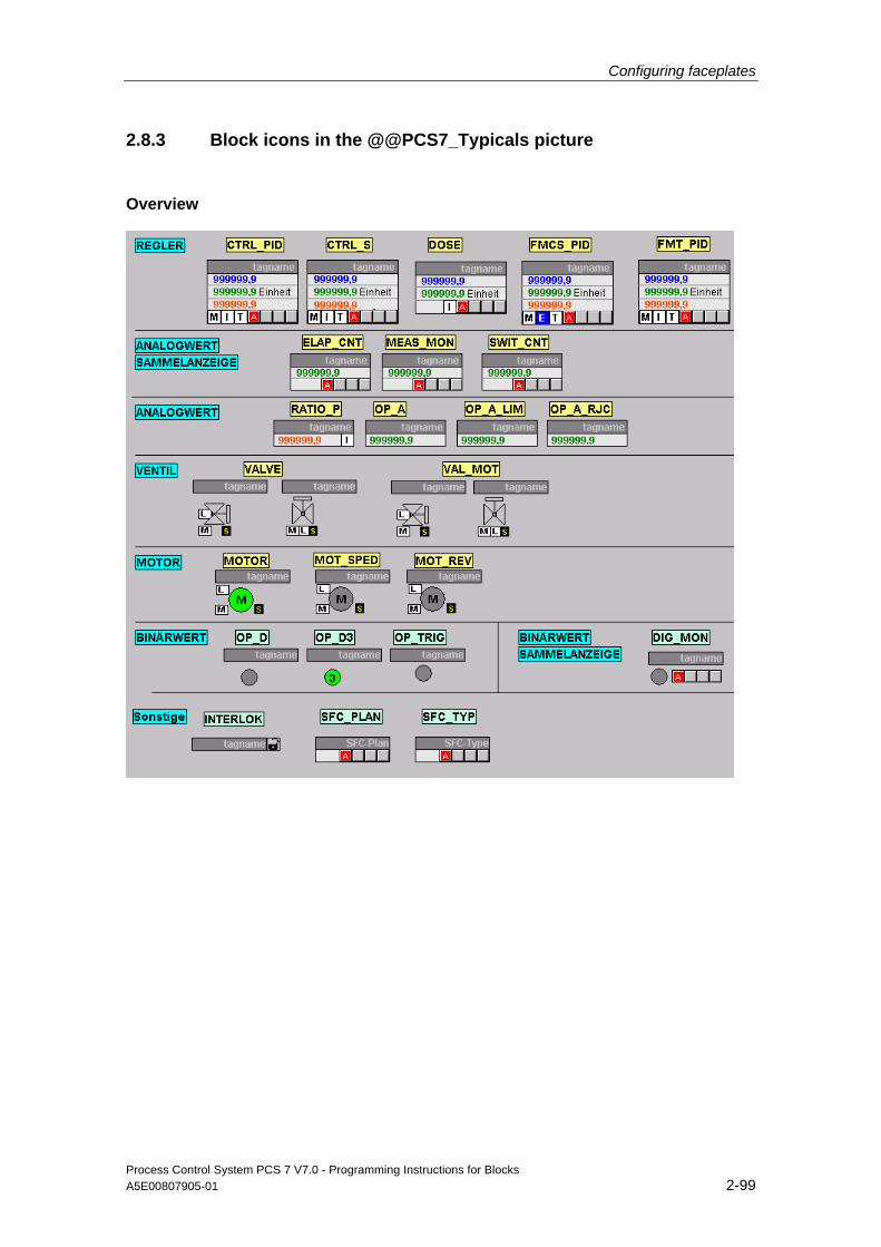
Configuring faceplates
Process Control System PCS 7 V7.0 - Programming Instructions for Blocks A5E00807905-01 2-99
2.8.3 Block icons in the @@PCS7_Typicals picture
Overview
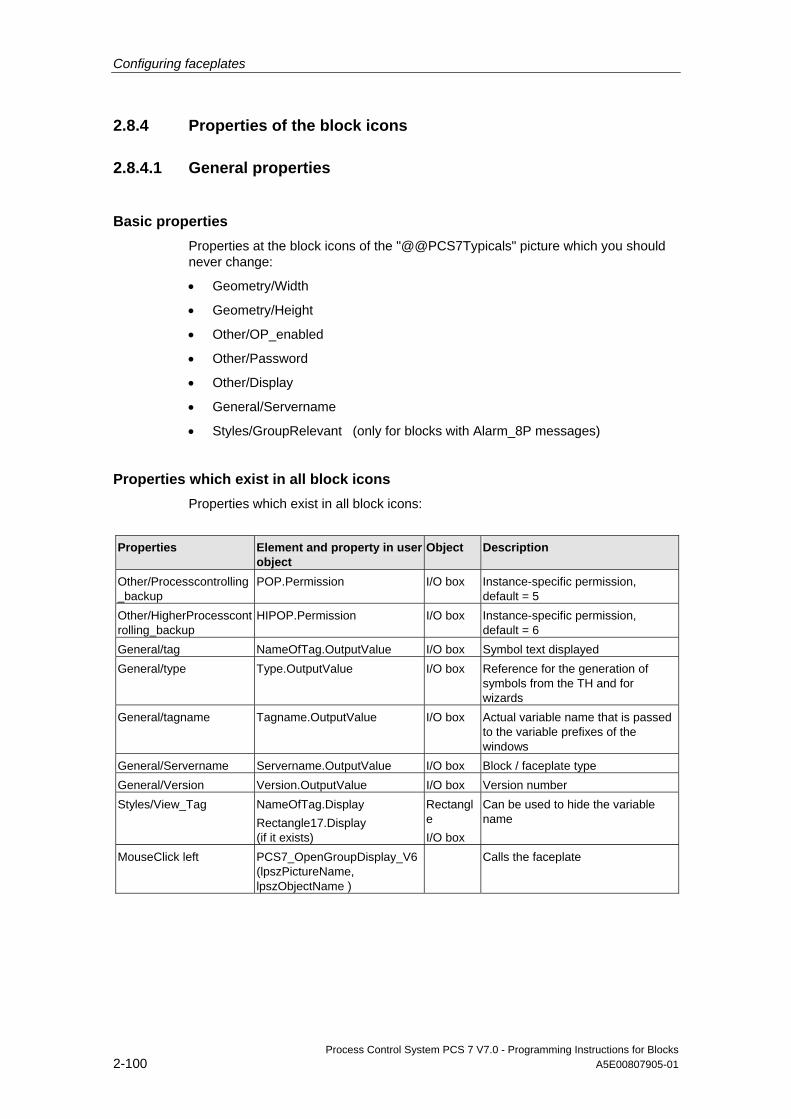
Configuring faceplates
Process Control System PCS 7 V7.0 - Programming Instructions for Blocks 2-100 A5E00807905-01
2.8.4 Properties of the block icons
2.8.4.1 General properties
Basic properties Properties at the block icons of the "@@PCS7Typicals" picture which you should never change:
• Geometry/Width
• Geometry/Height
• Other/OP_enabled
• Other/Password
• Other/Display
• General/Servername
• Styles/GroupRelevant (only for blocks with Alarm_8P messages)
Properties which exist in all block icons Properties which exist in all block icons:
Properties Element and property in user
object Object Description
Other/Processcontrolling_backup
POP.Permission I/O box Instance-specific permission, default = 5
Other/HigherProcesscontrolling_backup
HIPOP.Permission I/O box Instance-specific permission, default = 6
General/tag NameOfTag.OutputValue I/O box Symbol text displayed General/type Type.OutputValue I/O box Reference for the generation of
symbols from the TH and for wizards
General/tagname Tagname.OutputValue I/O box Actual variable name that is passed to the variable prefixes of the windows
General/Servername Servername.OutputValue I/O box Block / faceplate type General/Version Version.OutputValue I/O box Version number Styles/View_Tag NameOfTag.Display
Rectangle17.Display (if it exists)
Rectangle I/O box
Can be used to hide the variable name
MouseClick left PCS7_OpenGroupDisplay_V6 (lpszPictureName, lpszObjectName )
Calls the faceplate

Configuring faceplates
Process Control System PCS 7 V7.0 - Programming Instructions for Blocks A5E00807905-01 2-101
2.8.4.2 CTRL_PID
Properties See also chapter 2.8.4, "General properties"
Properties Element and property in user
object Object Description
Geometry Width = 110/Height = 77 General/UnitPV UnitPV.Text Stat.Text Display: PV unit General/ Unit_MAN_OP
Unit_MAN_OP.Text Stat.Text Display: MAN_OP unit
Links/ CollectValue
GroupDisplay.CollectValue GroupDisplay .EventState
Links/ SetpointValue
SetpointValue_Advanced AnalogDisplay.Value
AdvancedAnalogDis. Display: Setpoint
Links/ ProcessValue
ProcessValue_Advanced AnalogDisplay.Value
AdvancedAnalogDis. Display: Process value
Links/ OutputValue
OutputValue_Advanced AnalogDisplay.Value
AdvancedAnalogDis. Display: Manipulated variable
Links / LMN_SEL
Tracking_AdvancedStatus Display.Status
AdvancedStatusDis. Display: Manipulated variable correction
Links/ Mode_MAN_AUT
Manual_AdvancedStatus Display.Status
AdvancedStatusDis. Display: Manual/Auto
Links/ Mode_INT_EXT
External_Advanced StatusDisplay.Status
AdvancedStatusDis. Display: External/Internal
Styles/ ReturnPath
TrendFunctions2 .Output value
I/O box See section 2.1.8, "Configuring trend views"
Styles/ StandardTrend
TrendFunctions2 .CharacterSetSize
I/O box See section 2.1.8, "Configuring trend views"
Styles/ Format_InputValue
ProcessValue_Advanced AnalogDisplay.Format SetpointValue_Advanced AnalogDisplay.Format
AdvancedAnalogDis. AdvancedAnalogDis.
Formats the process value and setpoint numbers
Styles/Format_OutputValue
OutputValue_Advanced AnalogDisplay.Format
AdvancedAnalogDis. Formats the manipulated variable numbers
Styles/Format_xx Format_xx.OutputValue I/O box Additional format, see chapter 2.1.7, "Configuring number formats"
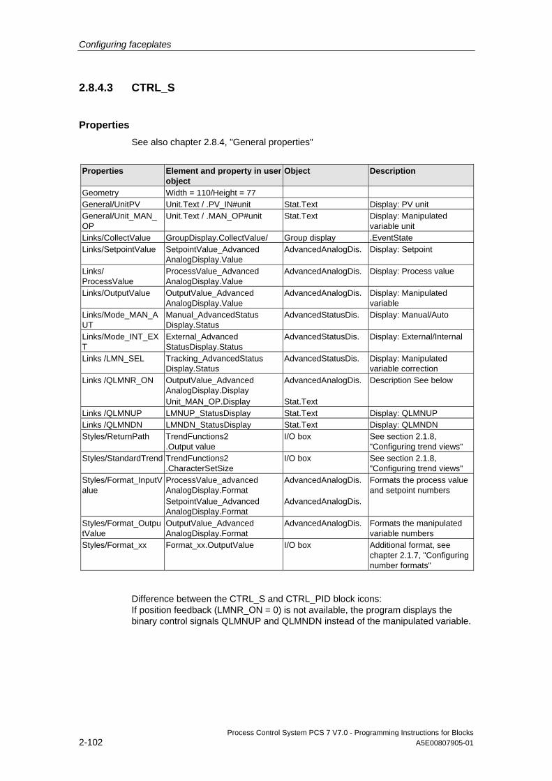
Configuring faceplates
Process Control System PCS 7 V7.0 - Programming Instructions for Blocks 2-102 A5E00807905-01
2.8.4.3 CTRL_S
Properties See also chapter 2.8.4, "General properties"
Properties Element and property in user
object Object Description
Geometry Width = 110/Height = 77 General/UnitPV Unit.Text / .PV_IN#unit Stat.Text Display: PV unit General/Unit_MAN_OP
Unit.Text / .MAN_OP#unit Stat.Text Display: Manipulated variable unit
Links/CollectValue GroupDisplay.CollectValue/ Group display .EventState Links/SetpointValue SetpointValue_Advanced
AnalogDisplay.Value AdvancedAnalogDis. Display: Setpoint
Links/ ProcessValue
ProcessValue_Advanced AnalogDisplay.Value
AdvancedAnalogDis. Display: Process value
Links/OutputValue OutputValue_Advanced AnalogDisplay.Value
AdvancedAnalogDis. Display: Manipulated variable
Links/Mode_MAN_AUT
Manual_AdvancedStatus Display.Status
AdvancedStatusDis. Display: Manual/Auto
Links/Mode_INT_EXT
External_Advanced StatusDisplay.Status
AdvancedStatusDis. Display: External/Internal
Links /LMN_SEL Tracking_AdvancedStatus Display.Status
AdvancedStatusDis. Display: Manipulated variable correction
Links /QLMNR_ON OutputValue_Advanced AnalogDisplay.Display Unit_MAN_OP.Display
AdvancedAnalogDis. Stat.Text
Description See below
Links /QLMNUP LMNUP_StatusDisplay Stat.Text Display: QLMNUP Links /QLMNDN LMNDN_StatusDisplay Stat.Text Display: QLMNDN Styles/ReturnPath TrendFunctions2
.Output value I/O box See section 2.1.8,
"Configuring trend views" Styles/StandardTrend TrendFunctions2
.CharacterSetSize I/O box See section 2.1.8,
"Configuring trend views" Styles/Format_InputValue
ProcessValue_advanced AnalogDisplay.Format SetpointValue_Advanced AnalogDisplay.Format
AdvancedAnalogDis. AdvancedAnalogDis.
Formats the process value and setpoint numbers
Styles/Format_OutputValue
OutputValue_Advanced AnalogDisplay.Format
AdvancedAnalogDis. Formats the manipulated variable numbers
Styles/Format_xx Format_xx.OutputValue I/O box Additional format, see chapter 2.1.7, "Configuring number formats"
Difference between the CTRL_S and CTRL_PID block icons: If position feedback (LMNR_ON = 0) is not available, the program displays the binary control signals QLMNUP and QLMNDN instead of the manipulated variable.
Configuring faceplates
Process Control System PCS 7 V7.0 - Programming Instructions for Blocks A5E00807905-01 2-103
The visibility of these texts is also controlled by scripts. The scripts are called when you change QLMNUP and QLMNDN.
Note
The "OutputValue_AdvancedAnalogDisplay“ and "Unit_MAN_OP“ objects must always be brought to the foreground in the user object, in order to ensure proper functioning of the visualization control.
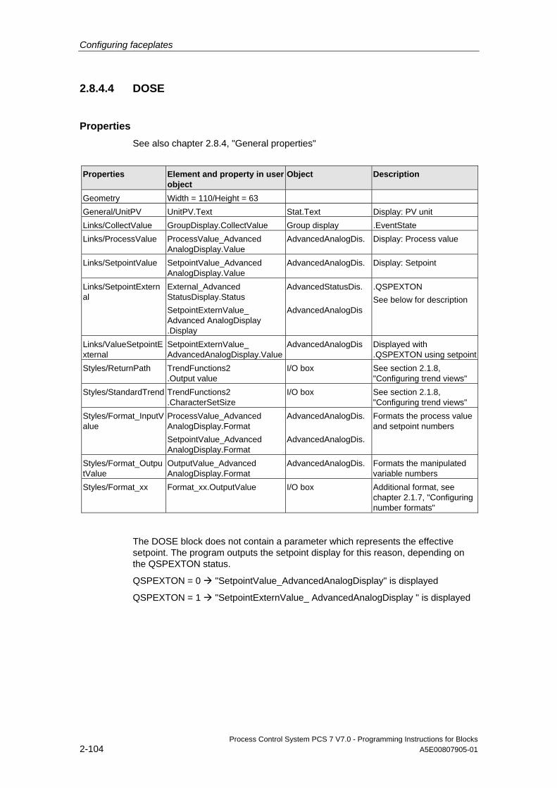
Configuring faceplates
Process Control System PCS 7 V7.0 - Programming Instructions for Blocks 2-104 A5E00807905-01
2.8.4.4 DOSE
Properties See also chapter 2.8.4, "General properties"
Properties Element and property in user
object Object Description
Geometry Width = 110/Height = 63 General/UnitPV UnitPV.Text Stat.Text Display: PV unit Links/CollectValue GroupDisplay.CollectValue Group display .EventState Links/ProcessValue ProcessValue_Advanced
AnalogDisplay.Value AdvancedAnalogDis. Display: Process value
Links/SetpointValue SetpointValue_Advanced AnalogDisplay.Value
AdvancedAnalogDis. Display: Setpoint
Links/SetpointExternal
External_Advanced StatusDisplay.Status SetpointExternValue_ Advanced AnalogDisplay .Display
AdvancedStatusDis. AdvancedAnalogDis
.QSPEXTON See below for description
Links/ValueSetpointExternal
SetpointExternValue_ AdvancedAnalogDisplay.Value
AdvancedAnalogDis Displayed with .QSPEXTON using setpoint
Styles/ReturnPath TrendFunctions2 .Output value
I/O box See section 2.1.8, "Configuring trend views"
Styles/StandardTrend TrendFunctions2 .CharacterSetSize
I/O box See section 2.1.8, "Configuring trend views"
Styles/Format_InputValue
ProcessValue_Advanced AnalogDisplay.Format SetpointValue_Advanced AnalogDisplay.Format
AdvancedAnalogDis. AdvancedAnalogDis.
Formats the process value and setpoint numbers
Styles/Format_OutputValue
OutputValue_Advanced AnalogDisplay.Format
AdvancedAnalogDis. Formats the manipulated variable numbers
Styles/Format_xx Format_xx.OutputValue I/O box Additional format, see chapter 2.1.7, "Configuring number formats"
The DOSE block does not contain a parameter which represents the effective setpoint. The program outputs the setpoint display for this reason, depending on the QSPEXTON status.
QSPEXTON = 0 "SetpointValue_AdvancedAnalogDisplay" is displayed
QSPEXTON = 1 "SetpointExternValue_ AdvancedAnalogDisplay " is displayed
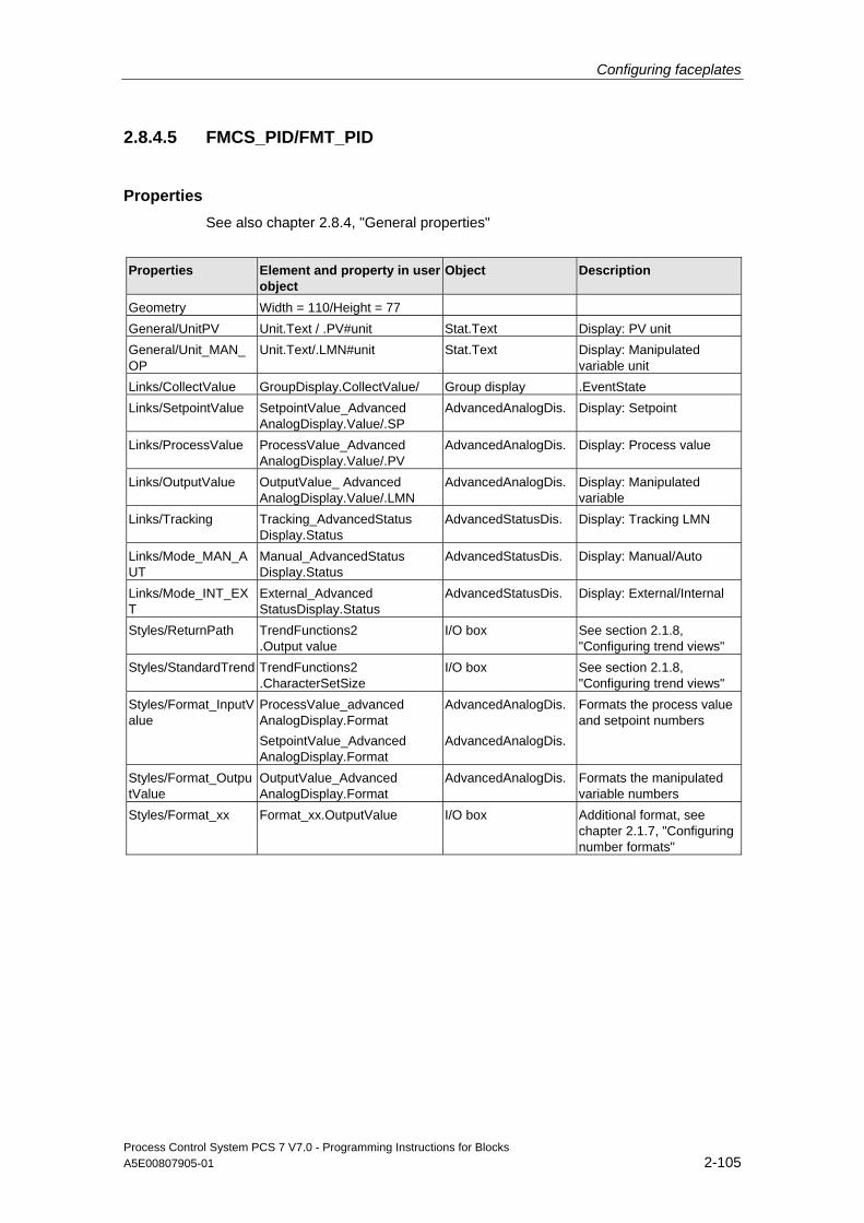
Configuring faceplates
Process Control System PCS 7 V7.0 - Programming Instructions for Blocks A5E00807905-01 2-105
2.8.4.5 FMCS_PID/FMT_PID
Properties See also chapter 2.8.4, "General properties"
Properties Element and property in user
object Object Description
Geometry Width = 110/Height = 77 General/UnitPV Unit.Text / .PV#unit Stat.Text Display: PV unit General/Unit_MAN_OP
Unit.Text/.LMN#unit Stat.Text Display: Manipulated variable unit
Links/CollectValue GroupDisplay.CollectValue/ Group display .EventState Links/SetpointValue SetpointValue_Advanced
AnalogDisplay.Value/.SP AdvancedAnalogDis. Display: Setpoint
Links/ProcessValue ProcessValue_Advanced AnalogDisplay.Value/.PV
AdvancedAnalogDis. Display: Process value
Links/OutputValue OutputValue_ Advanced AnalogDisplay.Value/.LMN
AdvancedAnalogDis. Display: Manipulated variable
Links/Tracking Tracking_AdvancedStatus Display.Status
AdvancedStatusDis. Display: Tracking LMN
Links/Mode_MAN_AUT
Manual_AdvancedStatus Display.Status
AdvancedStatusDis. Display: Manual/Auto
Links/Mode_INT_EXT
External_Advanced StatusDisplay.Status
AdvancedStatusDis. Display: External/Internal
Styles/ReturnPath TrendFunctions2 .Output value
I/O box See section 2.1.8, "Configuring trend views"
Styles/StandardTrend TrendFunctions2 .CharacterSetSize
I/O box See section 2.1.8, "Configuring trend views"
Styles/Format_InputValue
ProcessValue_advanced AnalogDisplay.Format SetpointValue_Advanced AnalogDisplay.Format
AdvancedAnalogDis. AdvancedAnalogDis.
Formats the process value and setpoint numbers
Styles/Format_OutputValue
OutputValue_Advanced AnalogDisplay.Format
AdvancedAnalogDis. Formats the manipulated variable numbers
Styles/Format_xx Format_xx.OutputValue I/O box Additional format, see chapter 2.1.7, "Configuring number formats"
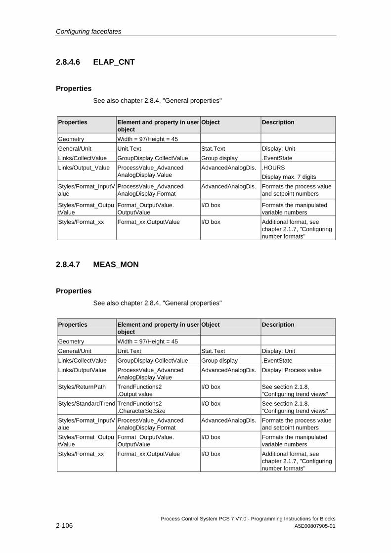
Configuring faceplates
Process Control System PCS 7 V7.0 - Programming Instructions for Blocks 2-106 A5E00807905-01
2.8.4.6 ELAP_CNT
Properties See also chapter 2.8.4, "General properties"
Properties Element and property in user
object Object Description
Geometry Width = 97/Height = 45 General/Unit Unit.Text Stat.Text Display: Unit Links/CollectValue GroupDisplay.CollectValue Group display .EventState Links/Output_Value ProcessValue_Advanced
AnalogDisplay.Value AdvancedAnalogDis. .HOURS
Display max. 7 digits Styles/Format_InputValue
ProcessValue_Advanced AnalogDisplay.Format
AdvancedAnalogDis.
Formats the process value and setpoint numbers
Styles/Format_OutputValue
Format_OutputValue. OutputValue
I/O box Formats the manipulated variable numbers
Styles/Format_xx Format_xx.OutputValue I/O box Additional format, see chapter 2.1.7, "Configuring number formats"
2.8.4.7 MEAS_MON
Properties See also chapter 2.8.4, "General properties"
Properties Element and property in user
object Object Description
Geometry Width = 97/Height = 45 General/Unit Unit.Text Stat.Text Display: Unit Links/CollectValue GroupDisplay.CollectValue Group display .EventState Links/OutputValue ProcessValue_Advanced
AnalogDisplay.Value AdvancedAnalogDis. Display: Process value
Styles/ReturnPath TrendFunctions2 .Output value
I/O box See section 2.1.8, "Configuring trend views"
Styles/StandardTrend TrendFunctions2 .CharacterSetSize
I/O box See section 2.1.8, "Configuring trend views"
Styles/Format_InputValue
ProcessValue_Advanced AnalogDisplay.Format
AdvancedAnalogDis. Formats the process value and setpoint numbers
Styles/Format_OutputValue
Format_OutputValue. OutputValue
I/O box Formats the manipulated variable numbers
Styles/Format_xx Format_xx.OutputValue I/O box Additional format, see chapter 2.1.7, "Configuring number formats"
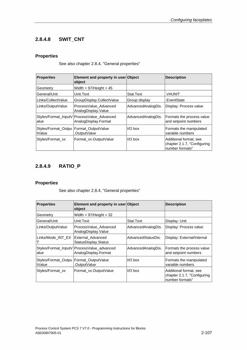
Configuring faceplates
Process Control System PCS 7 V7.0 - Programming Instructions for Blocks A5E00807905-01 2-107
2.8.4.8 SWIT_CNT
Properties See also chapter 2.8.4, "General properties"
Properties Element and property in user
object Object Description
Geometry Width = 97/Height = 45 General/Unit Unit.Text Stat.Text .V#UNIT Links/CollectValue GroupDisplay.CollectValue Group display .EventState Links/OutputValue ProcessValue_Advanced
AnalogDisplay.Value AdvancedAnalogDis. Display: Process value
Styles/Format_InputValue
ProcessValue_Advanced AnalogDisplay.Format
AdvancedAnalogDis.
Formats the process value and setpoint numbers
Styles/Format_OutputValue
Format_OutputValue .OutputValue
I/O box Formats the manipulated variable numbers
Styles/Format_xx Format_xx.OutputValue I/O box Additional format, see chapter 2.1.7, "Configuring number formats"
2.8.4.9 RATIO_P
Properties See also chapter 2.8.4, "General properties"
Properties Element and property in user
object Object Description
Geometry Width = 97/Height = 32 General/Unit Unit.Text Stat.Text Display: Unit Links/OutputValue ProcessValue_Advanced
AnalogDisplay.Value AdvancedAnalogDis. Display: Process value
Links/Mode_INT_EXT
External_Advanced StatusDisplay.Status
AdvancedStatusDis. Display: External/Internal
Styles/Format_InputValue
ProcessValue_advanced AnalogDisplay.Format
AdvancedAnalogDis.
Formats the process value and setpoint numbers
Styles/Format_OutputValue
Format_OutputValue .OutputValue
I/O box Formats the manipulated variable numbers
Styles/Format_xx Format_xx.OutputValue I/O box Additional format, see chapter 2.1.7, "Configuring number formats"
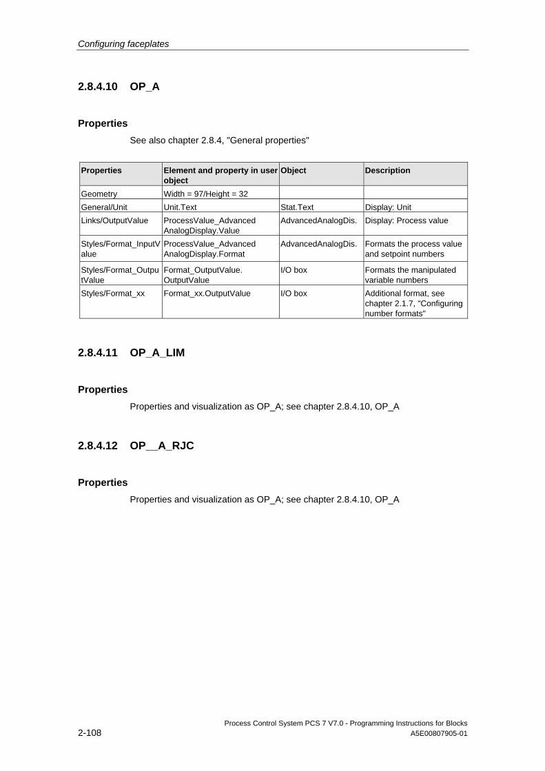
Configuring faceplates
Process Control System PCS 7 V7.0 - Programming Instructions for Blocks 2-108 A5E00807905-01
2.8.4.10 OP_A
Properties See also chapter 2.8.4, "General properties"
Properties Element and property in user
object Object Description
Geometry Width = 97/Height = 32 General/Unit Unit.Text Stat.Text Display: Unit Links/OutputValue ProcessValue_Advanced
AnalogDisplay.Value AdvancedAnalogDis. Display: Process value
Styles/Format_InputValue
ProcessValue_Advanced AnalogDisplay.Format
AdvancedAnalogDis.
Formats the process value and setpoint numbers
Styles/Format_OutputValue
Format_OutputValue. OutputValue
I/O box Formats the manipulated variable numbers
Styles/Format_xx Format_xx.OutputValue I/O box Additional format, see chapter 2.1.7, "Configuring number formats"
2.8.4.11 OP_A_LIM
Properties Properties and visualization as OP_A; see chapter 2.8.4.10, OP_A
2.8.4.12 OP__A_RJC
Properties Properties and visualization as OP_A; see chapter 2.8.4.10, OP_A
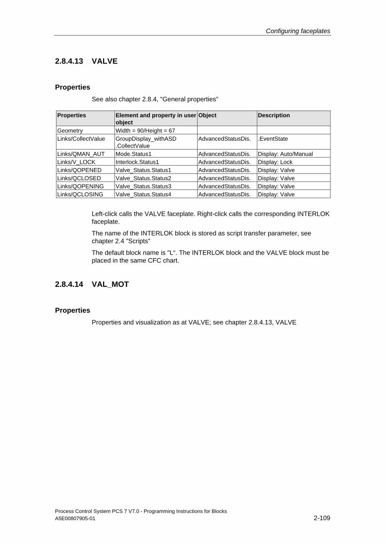
Configuring faceplates
Process Control System PCS 7 V7.0 - Programming Instructions for Blocks A5E00807905-01 2-109
2.8.4.13 VALVE
Properties See also chapter 2.8.4, "General properties"
Properties Element and property in user object
Object Description
Geometry Width = 90/Height = 67 Links/CollectValue GroupDisplay_withASD
.CollectValue AdvancedStatusDis. .EventState
Links/QMAN_AUT Mode.Status1 AdvancedStatusDis. Display: Auto/Manual Links/V_LOCK Interlock.Status1 AdvancedStatusDis. Display: Lock Links/QOPENED Valve_Status.Status1 AdvancedStatusDis. Display: Valve Links/QCLOSED Valve_Status.Status2 AdvancedStatusDis. Display: Valve Links/QOPENING Valve_Status.Status3 AdvancedStatusDis. Display: Valve Links/QCLOSING Valve_Status.Status4 AdvancedStatusDis. Display: Valve
Left-click calls the VALVE faceplate. Right-click calls the corresponding INTERLOK faceplate.
The name of the INTERLOK block is stored as script transfer parameter, see chapter 2.4 "Scripts"
The default block name is "L“. The INTERLOK block and the VALVE block must be placed in the same CFC chart.
2.8.4.14 VAL_MOT
Properties Properties and visualization as at VALVE; see chapter 2.8.4.13, VALVE
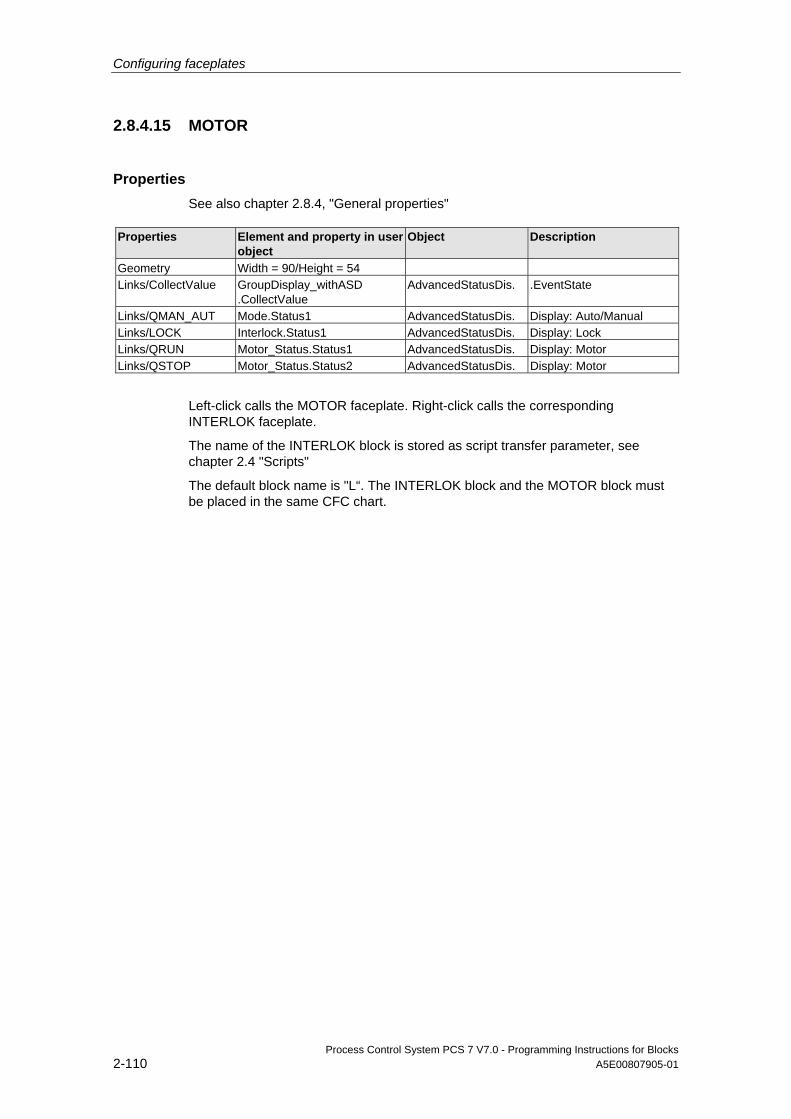
Configuring faceplates
Process Control System PCS 7 V7.0 - Programming Instructions for Blocks 2-110 A5E00807905-01
2.8.4.15 MOTOR
Properties See also chapter 2.8.4, "General properties"
Properties Element and property in user object
Object Description
Geometry Width = 90/Height = 54 Links/CollectValue GroupDisplay_withASD
.CollectValue AdvancedStatusDis. .EventState
Links/QMAN_AUT Mode.Status1 AdvancedStatusDis. Display: Auto/Manual Links/LOCK Interlock.Status1 AdvancedStatusDis. Display: Lock Links/QRUN Motor_Status.Status1 AdvancedStatusDis. Display: Motor Links/QSTOP Motor_Status.Status2 AdvancedStatusDis. Display: Motor
Left-click calls the MOTOR faceplate. Right-click calls the corresponding INTERLOK faceplate.
The name of the INTERLOK block is stored as script transfer parameter, see chapter 2.4 "Scripts"
The default block name is "L“. The INTERLOK block and the MOTOR block must be placed in the same CFC chart.
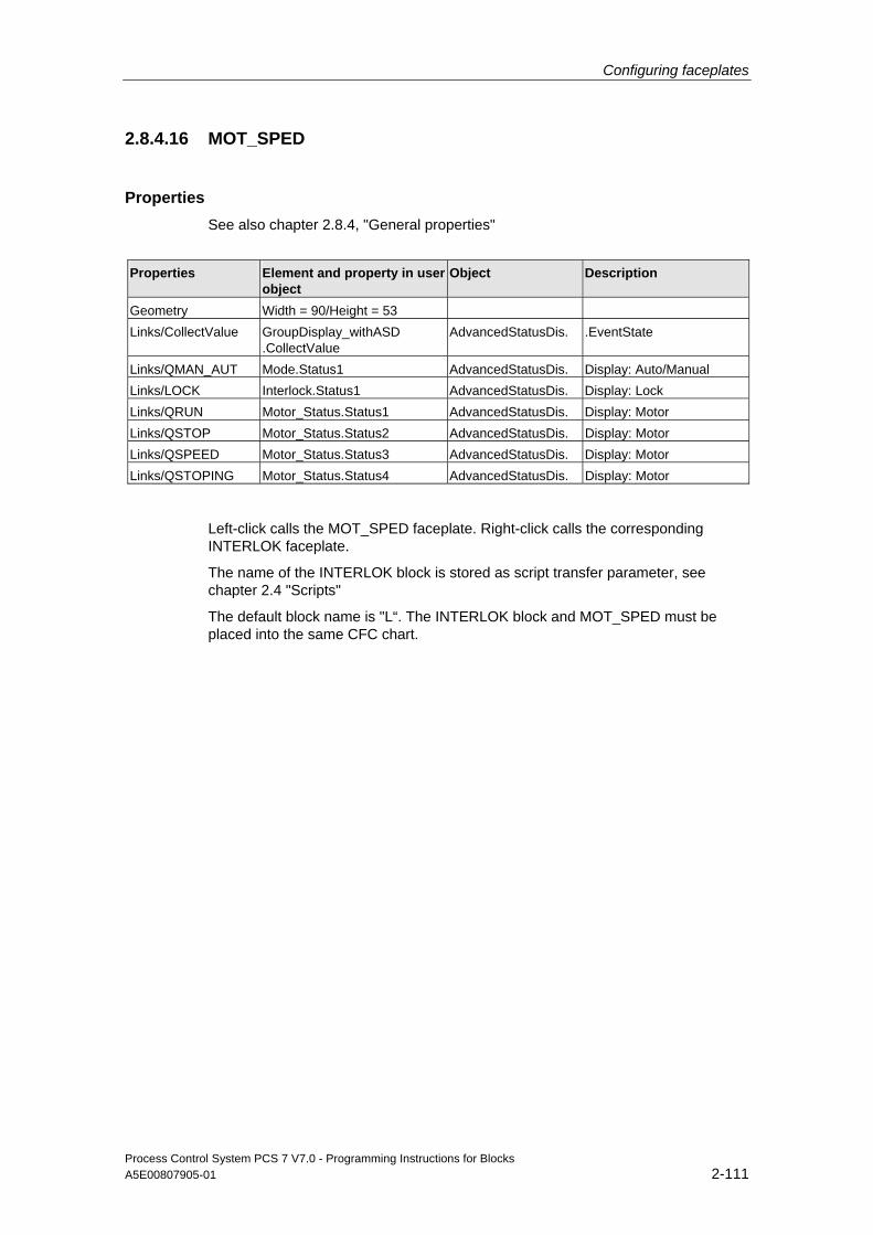
Configuring faceplates
Process Control System PCS 7 V7.0 - Programming Instructions for Blocks A5E00807905-01 2-111
2.8.4.16 MOT_SPED
Properties See also chapter 2.8.4, "General properties"
Properties Element and property in user
object Object Description
Geometry Width = 90/Height = 53 Links/CollectValue GroupDisplay_withASD
.CollectValue AdvancedStatusDis. .EventState
Links/QMAN_AUT Mode.Status1 AdvancedStatusDis. Display: Auto/Manual Links/LOCK Interlock.Status1 AdvancedStatusDis. Display: Lock Links/QRUN Motor_Status.Status1 AdvancedStatusDis. Display: Motor Links/QSTOP Motor_Status.Status2 AdvancedStatusDis. Display: Motor Links/QSPEED Motor_Status.Status3 AdvancedStatusDis. Display: Motor Links/QSTOPING Motor_Status.Status4 AdvancedStatusDis. Display: Motor
Left-click calls the MOT_SPED faceplate. Right-click calls the corresponding INTERLOK faceplate.
The name of the INTERLOK block is stored as script transfer parameter, see chapter 2.4 "Scripts"
The default block name is "L“. The INTERLOK block and MOT_SPED must be placed into the same CFC chart.
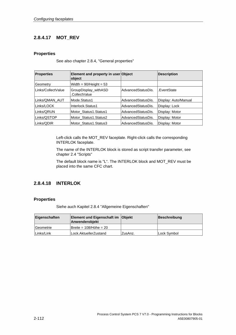
Configuring faceplates
Process Control System PCS 7 V7.0 - Programming Instructions for Blocks 2-112 A5E00807905-01
2.8.4.17 MOT_REV
Properties See also chapter 2.8.4, "General properties"
Properties Element and property in user
object Object Description
Geometry Width = 90/Height = 53 Links/CollectValue GroupDisplay_withASD
.CollectValue AdvancedStatusDis. .EventState
Links/QMAN_AUT Mode.Status1 AdvancedStatusDis. Display: Auto/Manual Links/LOCK Interlock.Status1 AdvancedStatusDis. Display: Lock Links/QRUN Motor_Status1.Status1 AdvancedStatusDis. Display: Motor Links/QSTOP Motor_Status1.Status2 AdvancedStatusDis. Display: Motor Links/QDIR Motor_Status1.Status3 AdvancedStatusDis. Display: Motor
Left-click calls the MOT_REV faceplate. Right-click calls the corresponding INTERLOK faceplate.
The name of the INTERLOK block is stored as script transfer parameter, see chapter 2.4 "Scripts"
The default block name is "L“. The INTERLOK block and MOT_REV must be placed into the same CFC chart.
2.8.4.18 INTERLOK
Properties Siehe auch Kapitel 2.8.4 "Allgemeine Eigenschaften"
Eigenschaften Element und Eigenschaft im Anwenderobjekt
Objekt Beschreibung
Geometrie Breite = 108/Höhe = 20 Links/Link Lock.AktuellerZustand ZusAnz. Lock Symbol
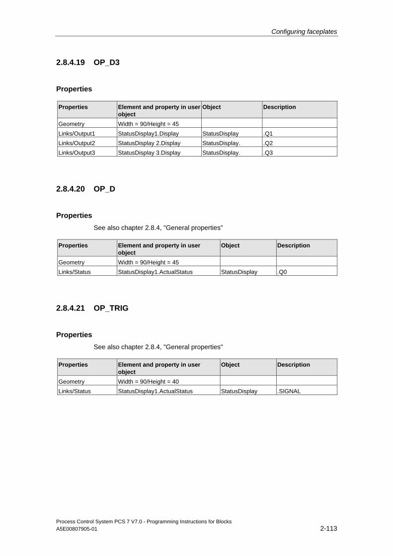
Configuring faceplates
Process Control System PCS 7 V7.0 - Programming Instructions for Blocks A5E00807905-01 2-113
2.8.4.19 OP_D3
Properties
Properties Element and property in user object
Object Description
Geometry Width = 90/Height = 45 Links/Output1 StatusDisplay1.Display StatusDisplay .Q1 Links/Output2 StatusDisplay 2.Display StatusDisplay. .Q2 Links/Output3 StatusDisplay 3.Display StatusDisplay. .Q3
2.8.4.20 OP_D
Properties See also chapter 2.8.4, "General properties"
Properties Element and property in user object
Object Description
Geometry Width = 90/Height = 45 Links/Status StatusDisplay1.ActualStatus StatusDisplay .Q0
2.8.4.21 OP_TRIG
Properties See also chapter 2.8.4, "General properties"
Properties Element and property in user object
Object Description
Geometry Width = 90/Height = 40 Links/Status StatusDisplay1.ActualStatus StatusDisplay .SIGNAL
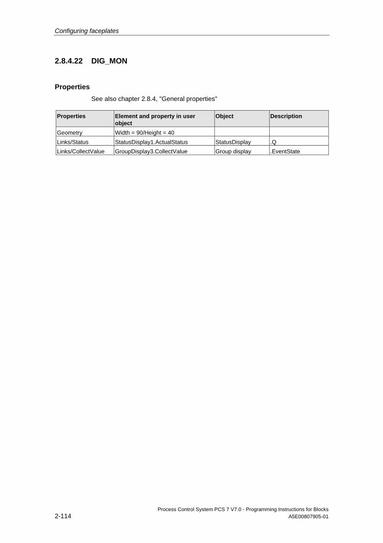
Configuring faceplates
Process Control System PCS 7 V7.0 - Programming Instructions for Blocks 2-114 A5E00807905-01
2.8.4.22 DIG_MON
Properties See also chapter 2.8.4, "General properties"
Properties Element and property in user object
Object Description
Geometry Width = 90/Height = 40 Links/Status StatusDisplay1.ActualStatus StatusDisplay .Q Links/CollectValue GroupDisplay3.CollectValue Group display .EventState
Process Control System PCS 7 V7.0 - Programming Instructions for Blocks A5E00807905-01 3-1
3 Creating the Online Help
3.1 Requirements
Software requirements:
• The "Notepad" ASCII editor integrated in WINDOWS or a similar editor for creating a registry file
• A tool for creating the help topics (for example, "RoboHelp")
3.2 Structure of the help file
Help file You create an online help system for your blocks by writing a help file using the help authoring system. You can assign this file a user-specific name. For reasons of clarity, you should use the name of your library or a name shared by your blocks. Example: "MYLIB__a.HLP".
Help topic Create a separate topic for each one of your blocks. Define the Online Help entry address for each topic ("Topic-ID" + "Map #") and enter this address in the registry (cf. chapter 3.3). You can select any addresses. However, these must be unambiguous in the online help system.
If you library is relatively complex, you can also create an hm file which contains all IDs used. You can assign the MAP IDs using the RoboHelp authoring tool of this file.
Entries in the hm file: // Headerfile for Online Help Mylib function blocks // #define CONTROL 0x10 // decimal 16 #define CONTROL2 0x11 // decimal 17 #define CONTROL3 0x12 // decimal 18 ....
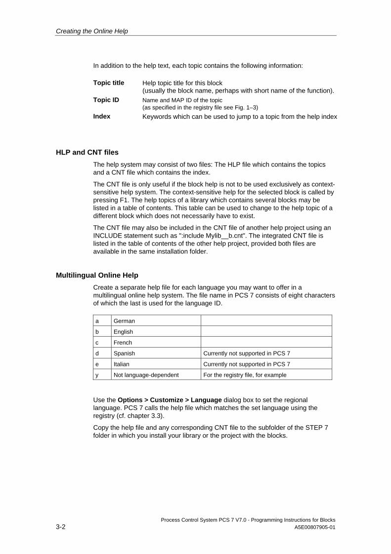
Creating the Online Help
Process Control System PCS 7 V7.0 - Programming Instructions for Blocks 3-2 A5E00807905-01
In addition to the help text, each topic contains the following information: Topic title Help topic title for this block
(usually the block name, perhaps with short name of the function). Topic ID Name and MAP ID of the topic
(as specified in the registry file see Fig. 1–3) Index Keywords which can be used to jump to a topic from the help index
HLP and CNT files The help system may consist of two files: The HLP file which contains the topics and a CNT file which contains the index.
The CNT file is only useful if the block help is not to be used exclusively as context-sensitive help system. The context-sensitive help for the selected block is called by pressing F1. The help topics of a library which contains several blocks may be listed in a table of contents. This table can be used to change to the help topic of a different block which does not necessarily have to exist.
The CNT file may also be included in the CNT file of another help project using an INCLUDE statement such as ":include Mylib__b.cnt". The integrated CNT file is listed in the table of contents of the other help project, provided both files are available in the same installation folder.
Multilingual Online Help Create a separate help file for each language you may want to offer in a multilingual online help system. The file name in PCS 7 consists of eight characters of which the last is used for the language ID. a German
b English
c French
d Spanish Currently not supported in PCS 7
e Italian Currently not supported in PCS 7
y Not language-dependent For the registry file, for example
Use the Options > Customize > Language dialog box to set the regional language. PCS 7 calls the help file which matches the set language using the registry (cf. chapter 3.3).
Copy the help file and any corresponding CNT file to the subfolder of the STEP 7 folder in which you install your library or the project with the blocks.
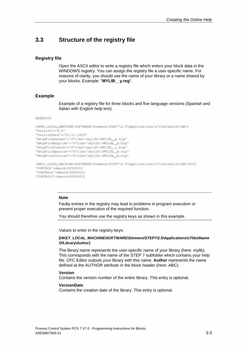
Creating the Online Help
Process Control System PCS 7 V7.0 - Programming Instructions for Blocks A5E00807905-01 3-3
3.3 Structure of the registry file
Registry file Open the ASCII editor to write a registry file which enters your block data in the WINDOWS registry. You can assign the registry file a user-specific name. For reasons of clarity, you should use the name of your library or a name shared by your blocks. Example: "MYLIB__y.reg".
Example Example of a registry file for three blocks and five language versions (Spanish and Italian with English help text).
REGEDIT4 [HKEY_LOCAL_MACHINE\SOFTWARE\Siemens\STEP7\2.0\Applications\s7libs\mylib\ABC] "Version"="0.2" "VersionDate"="23.11.2003" "HelpFileGerman"="S7libs\\mylib\\MYLIB__a.hlp" "HelpFileEnglish"="S7libs\\mylib\\MYLIB__b.hlp" "HelpFileFrench"="S7libs\\mylib\\MYLIB__c.hlp" "HelpFileSpanish"="S7libs\\mylib\\MYLIB__b.hlp" "HelpFileItalian"="S7libs\\mylib\\MYLIB__b.hlp" [HKEY_LOCAL_MACHINE\SOFTWARE\Siemens\STEP7\2.0\Applications\s7libs\mylib\ABC\XYZ] "CONTROL"=dword:00000010 "CONTROL2"=dword:00000011 "CONTROL3"=dword:00000012
Note
Faulty entries in the registry may lead to problems in program execution or prevent proper execution of the required function.
You should therefore use the registry keys as shown in this example.
Values to enter in the registry keys:
[HKEY_LOCAL_MACHINE\SOFTWARE\Siemens\STEP7\2.0\Applications\s7libs\NameOfLibrary\Author]
The library name represents the user-specific name of your library (here: mylib). This corresponds with the name of the STEP 7 subfolder which contains your help file. CFC Editor outputs your library with this name. Author represents the name defined at the AUTHOR attribute in the block header (here: ABC).
Version Contains the version number of the entire library. This entry is optional.
VersionDate Contains the creation date of the library. This entry is optional.
Creating the Online Help
Process Control System PCS 7 V7.0 - Programming Instructions for Blocks 3-4 A5E00807905-01
Path to the help file Contains the path relative to the STEP 7 folder for the required help file, for example:
"HelpFileGerman"="S7libs\\mylib\\MYLIB__a.hlp".
Please note that you have to enter two delimiters (\\). The program uses this entry to call the help file matching the language set in SIMATIC Manager.
Note
Italian and Spanish are currently not supported in PCS 7, so the help system is called in English language.
Next, enter the following keys:
[HKEY_LOCAL_MACHINE\SOFTWARE\Siemens\STEP7\2.0\Applications\s7libs\NameOfLibrary \Author\Family]
Family represents the name you defined at the FAMILY attribute in the block header (here: XYZ).
Below this, you must specify the block name, as specified in the header, for each block (see Fig. 1–3) with the entry address in the Help file, for example: "CONTROL"=dword:00000010. The entry address is the number of the Topic ID
When grouping your blocks by families, insert a separate key for each family in the registry file.
After you have executed this registry file (for example, by double-click), select a block from the CFC chart or in SIMATIC Manager and then press F1. The program determines and outputs the corresponding help file based on the language setting and on the block attributes AUTHOR, FAMILY, and FUNCTION_BLOCK in the WINDOWS registry.

Creating the Online Help
Process Control System PCS 7 V7.0 - Programming Instructions for Blocks A5E00807905-01 3-5
3.4 Special features for creating help files for SFC templates
By contrast to the information provided in chapter 3.2 and 3.3, and supplementary to this information, make allowances for the items shown below when creating online help files for SFC templates:
Storage location Copy the help files for the SFC templates to your installation folder. It is advisable to save these to the existing "S7Hlp" folder. This folder also contains the SFC online help files. This setup ensures that you can also change to the SFC online help from the help system you created. See below. The example registry entries shown below relates to this storage location.
Key entries
Author The "Author" entry is assigned by the SFC because this program compiles executable blocks from these SFC templates. Always: ES_SFC.
Family You can view the family name in the "Family" field (no empty string) in the properties dialog box of the SFC template. In the example: SFC
Name You can view the name of the SFC template in the "Name" field (no empty string) of the properties dialog box. In the example: "Dosi1" and "Heat1"
Example of a registry file for two block types and two language versions
Windows Registry Editor Version 5.00 [HKEY_LOCAL_MACHINE\SOFTWARE\Siemens\STEP7\2.0\Applications\s7libs\SFCTypes] [HKEY_LOCAL_MACHINE\SOFTWARE\Siemens\STEP7\2.0\Applications\s7libs\SFCTypes\ES_SFC] "HelpFileGerman"="S7Hlp\\SFC_Typa.hlp" "HelpFileENGLISH"="S7Hlp\\SFC_Typb.hlp" "Version"="1.1" "VersionDate"="14.11.2003" [HKEY_LOCAL_MACHINE\SOFTWARE\Siemens\STEP7\2.0\Applications\s7libs\SFCTypes\ES_SFC\SFC] "Dosi1"=dword:00000888 "Heat1"=dword:00000889
Changing to the SFC help system In order to be able to change to the SFC help system from the help you created, you can insert a jump to the (internal) table of contents of the SFC online help in the various topics. Syntax of this jump:
SFC help system!JumpID(`s7jsfcab.hlp',`IDH_CONTENTS')

Creating the Online Help
Process Control System PCS 7 V7.0 - Programming Instructions for Blocks 3-6 A5E00807905-01
Note
The jump address appended to the green text with double underscore !JumpID(`s7jsfcab.hlp',`IDH_CONTENTS') is formatted as hidden text.
Process Control System PCS 7 V7.0 - Programming Instructions for Blocks A5E00807905-01 4-1
4 Creating a library and setup
4.1 Requirements
In order to create a complete library and the corresponding Setup functions for distribution, you need a program for the creation of installation routines such as "InstallShield".
4.2 Creating a library
Procedure To group your blocks and/or SFC templates in a library:
1. Create a new S7 library and generate an S7 program therein
2. Enter the names and numbers of your blocks, including the corresponding comments in the symbol table of the library (this does not apply to SFC templates).
3. Sources: If you decide to include the source files of the blocks in your delivery, copy these from the source folder of your project to the source folder of the library
4. Blocks: Copy your blocks from the block folder of your project to the block folder of the library
Note:
- When using your multiple instance blocks to call blocks which are not generally available (SFBs, SFCs), you should also copy these to the block folder of the library.
- Exclude blocks the compiler has generated from the SFC templates when you copy the blocks
5. SFC templates: Create a chart folder if you have not yet done so Copy the SFC templates from the chart folder of your project to the chart folder of the library
Note: The blocks belonging to the SFC templates are also copied and saved to the block folder.
Creating a library and setup
Process Control System PCS 7 V7.0 - Programming Instructions for Blocks 4-2 A5E00807905-01
4.3 Create a Setup routine
Procedure 1. In order to use a Setup routine to install your library on the target computer,
create an installation script using the Setup authoring tool to perform the actions outlined below:
- Copy the block library to the S7LIBS subfolder of the STEP 7 folder
- Call the S7BIN\S7ALIBXX.EXE program in the STEP 7 folder in order to publish the new library in SIMATIC Manager
- Copy the help file (HLP and CNT file) to the subfolder of the STEP 7 folder to which the block library was copied (for example, subfolder S7LIBS\MYLIB)
- Call the registry file belonging to the help file
- Copy the prototype pictures to the options\pdl \FaceplateDesigner_V6 subfolder of the WinCC folder
- Copying the scripts to any subfolder of the aplib subfolder in the WinCC folder This folder should preferably be assigned the same name as the folder to which the block library was copied. Example: subfolder options\pdl\mylib).
- Setup of an uninstall option
2. Note that the block library and the online help system can only be installed when STEP 7 exists on the target computer The prototype pictures can only be installed in a subfolder of WinCC You should for this reason implement functions to query the existence of STEP 7 and WinCC in the installation dialog
3. You can also query the following items in the registry:
- Query the required value of the STEP7_VERSION name ("V5.2", for example) in the key HKEY_LOCAL_MACHINE\SOFTWARE\Siemens\STEP7
- You can also query the version name (V6.0 SP!, for example) in HKEY_LOCAL_MACHINE\SOFTWARE\Siemens\WinCC\Setup
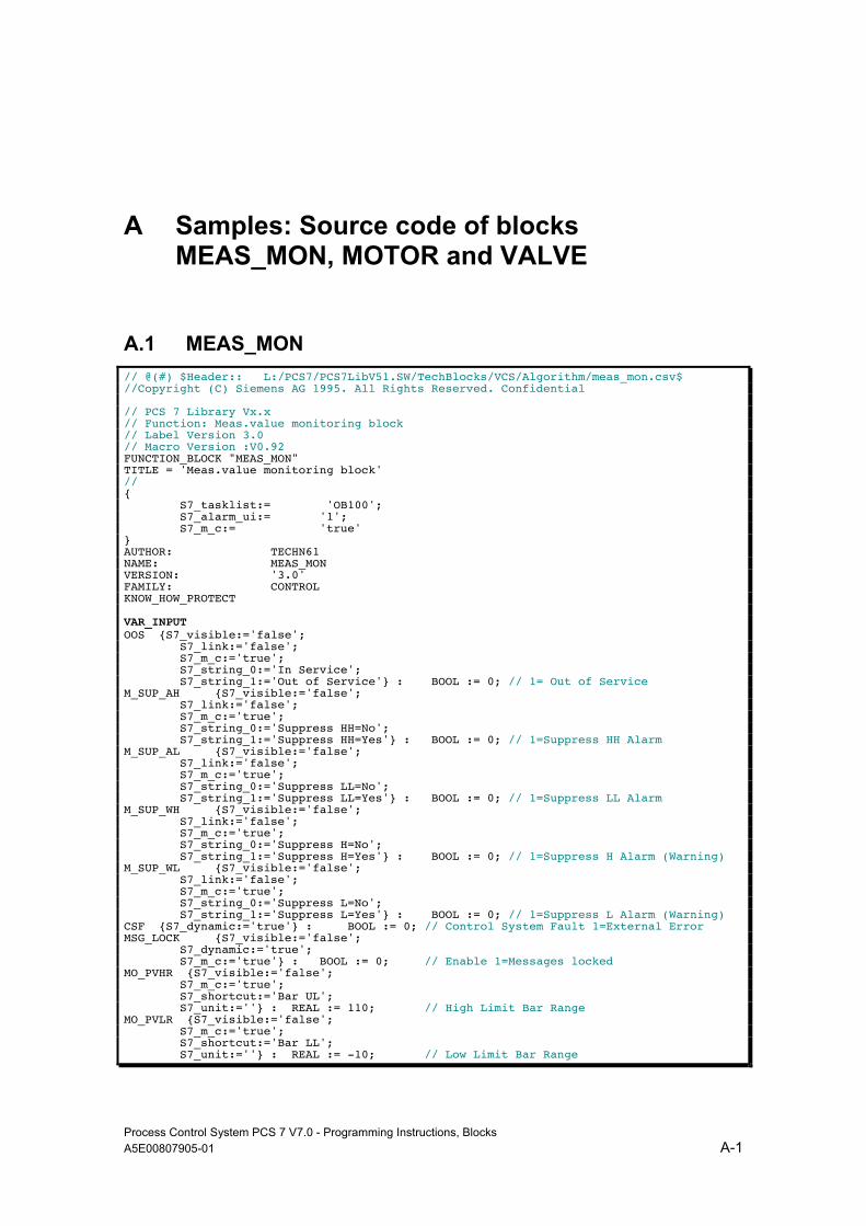
Process Control System PCS 7 V7.0 - Programming Instructions, Blocks A5E00807905-01 A-1
A Samples: Source code of blocks MEAS_MON, MOTOR and VALVE
A.1 MEAS_MON // @(#) $Header:: L:/PCS7/PCS7LibV51.SW/TechBlocks/VCS/Algorithm/meas_mon.csv$ //Copyright (C) Siemens AG 1995. All Rights Reserved. Confidential // PCS 7 Library Vx.x // Function: Meas.value monitoring block // Label Version 3.0 // Macro Version :V0.92 FUNCTION_BLOCK "MEAS_MON" TITLE = 'Meas.value monitoring block' // { S7_tasklist:= 'OB100'; S7_alarm_ui:= '1'; S7_m_c:= 'true' } AUTHOR: TECHN61 NAME: MEAS_MON VERSION: '3.0' FAMILY: CONTROL KNOW_HOW_PROTECT VAR_INPUT OOS {S7_visible:='false'; S7_link:='false'; S7_m_c:='true'; S7_string_0:='In Service'; S7_string_1:='Out of Service'} : BOOL := 0; // 1= Out of Service M_SUP_AH {S7_visible:='false'; S7_link:='false'; S7_m_c:='true'; S7_string_0:='Suppress HH=No'; S7_string_1:='Suppress HH=Yes'} : BOOL := 0; // 1=Suppress HH Alarm M_SUP_AL {S7_visible:='false'; S7_link:='false'; S7_m_c:='true'; S7_string_0:='Suppress LL=No'; S7_string_1:='Suppress LL=Yes'} : BOOL := 0; // 1=Suppress LL Alarm M_SUP_WH {S7_visible:='false'; S7_link:='false'; S7_m_c:='true'; S7_string_0:='Suppress H=No'; S7_string_1:='Suppress H=Yes'} : BOOL := 0; // 1=Suppress H Alarm (Warning) M_SUP_WL {S7_visible:='false'; S7_link:='false'; S7_m_c:='true'; S7_string_0:='Suppress L=No'; S7_string_1:='Suppress L=Yes'} : BOOL := 0; // 1=Suppress L Alarm (Warning) CSF {S7_dynamic:='true'} : BOOL := 0; // Control System Fault 1=External Error MSG_LOCK {S7_visible:='false'; S7_dynamic:='true'; S7_m_c:='true'} : BOOL := 0; // Enable 1=Messages locked MO_PVHR {S7_visible:='false'; S7_m_c:='true'; S7_shortcut:='Bar UL'; S7_unit:=''} : REAL := 110; // High Limit Bar Range MO_PVLR {S7_visible:='false'; S7_m_c:='true'; S7_shortcut:='Bar LL'; S7_unit:=''} : REAL := -10; // Low Limit Bar Range

Samples: Source code of blocks MEAS_MON, MOTOR and VALVE
Process Control System PCS 7 V7.0 - Programming Instructions, Blocks A-2 A5E00807905-01
USTATUS {S7_visible:='false'} : WORD := 0; // User Status Bits U {S7_qc:='true'; S7_dynamic:='true'; S7_m_c:='true'; S7_shortcut:='PV'; S7_unit:=''} : REAL := 0; // Analog Input (Measured Value) QC_U : BYTE := 16#80; // Quality Code for Input U U_AH {S7_link:='false'; S7_edit:='para'; S7_m_c:='true'; S7_shortcut:='HH alarm'; S7_unit:=''} : REAL := 100; // HH Alarm Limit U_WH {S7_link:='false'; S7_edit:='para'; S7_m_c:='true'; S7_shortcut:='H alarm'; S7_unit:=''} : REAL := 95; // H Alarm Limit (Warning) U_WL {S7_link:='false'; S7_edit:='para'; S7_m_c:='true'; S7_shortcut:='L alarm'; S7_unit:=''} : REAL := -3; // L Alarm Limit (Warning) U_AL {S7_link:='false'; S7_edit:='para'; S7_m_c:='true'; S7_shortcut:='LL alarm'; S7_unit:=''} : REAL := -5; // LL Alarm Limit HYS {S7_link:='false'; S7_m_c:='true'; S7_shortcut:='Hysteresis'; S7_unit:=''} : REAL := 5; // Hysteresis of Analog Input MSG_EVID {S7_visible:='false'; S7_link:='false'; S7_param :='false'; S7_server:='alarm_archiv';S7_a_type:='alarm_8p'} : DWORD := 0; // Message ID BA_EN {S7_visible:='false'; S7_m_c:='true'} : BOOL := 0; // Batch Enable OCCUPIED {S7_visible:='false'; S7_m_c:='true'} : BOOL := 0; // Occupied by Batch BA_ID {S7_visible:='false'; S7_m_c:='true'} : DWORD := 0; // Batch ID BA_NA {S7_visible:='false'; S7_m_c:='true'} : STRING[32] := ''; // Batch Name STEP_NO {S7_visible:='false'; S7_m_c:='true'} : DWORD := 0; // Batch Step Number RUNUPCYC {S7_visible:='false'; S7_link:='false'} : INT := 3; // Number of Run Up Cycles END_VAR VAR_IN_OUT AUX_PR05 {S7_visible:='false'} : ANY; // Auxiliary Value 5 AUX_PR06 {S7_visible:='false'} : ANY; // Auxiliary Value 6 AUX_PR07 {S7_visible:='false'} : ANY; // Auxiliary Value 7 AUX_PR08 {S7_visible:='false'} : ANY; // Auxiliary Value 8 AUX_PR09 {S7_visible:='false'} : ANY; // Auxiliary Value 9 AUX_PR10 {S7_visible:='false'} : ANY; // Auxiliary Value 10 END_VAR VAR_OUTPUT QERR {S7_visible:='false'; S7_m_c:='true'} : BOOL := 1; // 1=Error QH_ALM {S7_dynamic:='true'} : BOOL := 0; // 1=HH-Alarm active QL_ALM {S7_dynamic:='true'} : BOOL := 0; // 1=LL Alarm active QH_WRN {S7_dynamic:='true'} : BOOL := 0; // 1=H Alarm active (Warning) QL_WRN {S7_dynamic:='true'} : BOOL := 0; // 1=L Alarm active (Warning) QMSG_ERR {S7_visible:='false'; S7_dynamic:='true'} : BOOL := 0; // 1=Message ERROR QMSG_SUP {S7_visible:='false'; S7_dynamic:='true'; S7_m_c:='true'} : BOOL := 0; // 1=Message Suppression Active MSG_STAT {S7_visible:='false'; S7_dynamic:='true'} : WORD := 0; // Message: STATUS output MSG_ACK {S7_visible:='false'; S7_dynamic:='true'} : WORD := 0; // Message: ACK_STATE output VSTATUS {S7_visible:='false'; S7_m_c:='true'} : DWORD := 0; // Status word END_VAR
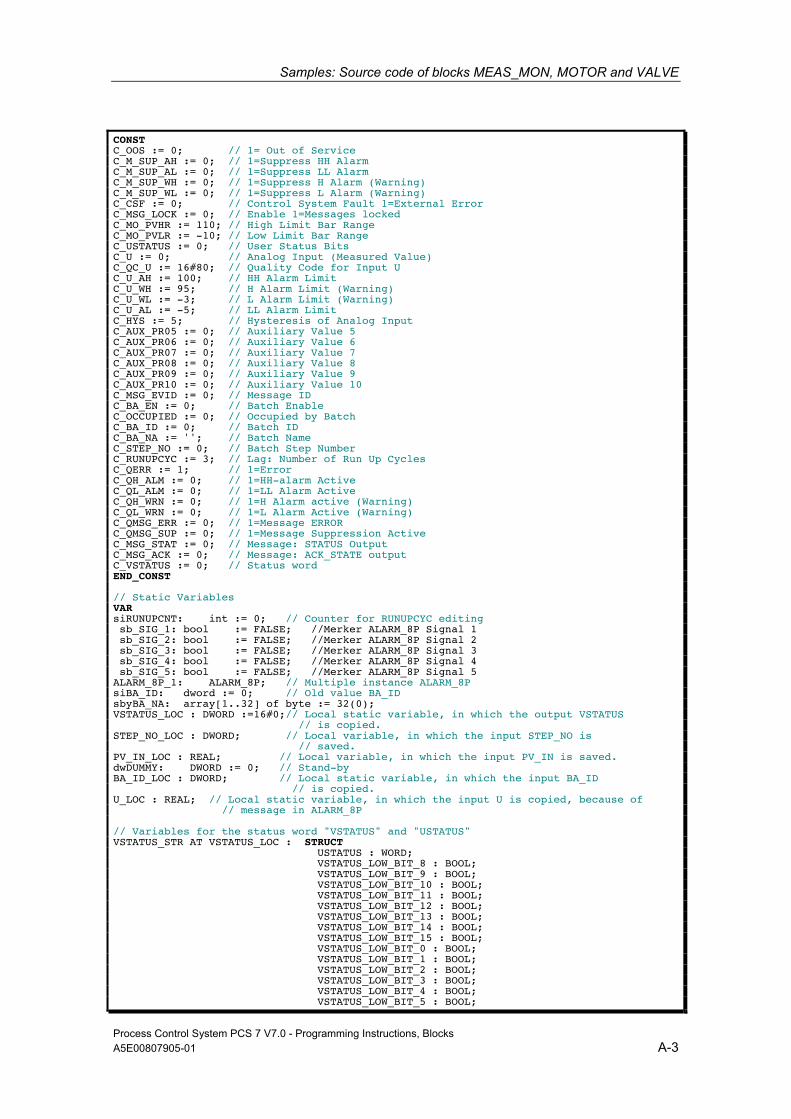
Samples: Source code of blocks MEAS_MON, MOTOR and VALVE
Process Control System PCS 7 V7.0 - Programming Instructions, Blocks A5E00807905-01 A-3
CONST C_OOS := 0; // 1= Out of Service C_M_SUP_AH := 0; // 1=Suppress HH Alarm C_M_SUP_AL := 0; // 1=Suppress LL Alarm C_M_SUP_WH := 0; // 1=Suppress H Alarm (Warning) C_M_SUP_WL := 0; // 1=Suppress L Alarm (Warning) C_CSF := 0; // Control System Fault 1=External Error C_MSG_LOCK := 0; // Enable 1=Messages locked C_MO_PVHR := 110; // High Limit Bar Range C_MO_PVLR := -10; // Low Limit Bar Range C_USTATUS := 0; // User Status Bits C_U := 0; // Analog Input (Measured Value) C_QC_U := 16#80; // Quality Code for Input U C_U_AH := 100; // HH Alarm Limit C_U_WH := 95; // H Alarm Limit (Warning) C_U_WL := -3; // L Alarm Limit (Warning) C_U_AL := -5; // LL Alarm Limit C_HYS := 5; // Hysteresis of Analog Input C_AUX_PR05 := 0; // Auxiliary Value 5 C_AUX_PR06 := 0; // Auxiliary Value 6 C_AUX_PR07 := 0; // Auxiliary Value 7 C_AUX_PR08 := 0; // Auxiliary Value 8 C_AUX_PR09 := 0; // Auxiliary Value 9 C_AUX_PR10 := 0; // Auxiliary Value 10 C_MSG_EVID := 0; // Message ID C_BA_EN := 0; // Batch Enable C_OCCUPIED := 0; // Occupied by Batch C_BA_ID := 0; // Batch ID C_BA_NA := ''; // Batch Name C_STEP_NO := 0; // Batch Step Number C_RUNUPCYC := 3; // Lag: Number of Run Up Cycles C_QERR := 1; // 1=Error C_QH_ALM := 0; // 1=HH-alarm Active C_QL_ALM := 0; // 1=LL Alarm Active C_QH_WRN := 0; // 1=H Alarm active (Warning) C_QL_WRN := 0; // 1=L Alarm Active (Warning) C_QMSG_ERR := 0; // 1=Message ERROR C_QMSG_SUP := 0; // 1=Message Suppression Active C_MSG_STAT := 0; // Message: STATUS Output C_MSG_ACK := 0; // Message: ACK_STATE output C_VSTATUS := 0; // Status word END_CONST // Static Variables VAR siRUNUPCNT: int := 0; // Counter for RUNUPCYC editing sb_SIG_1: bool := FALSE; //Merker ALARM_8P Signal 1 sb_SIG_2: bool := FALSE; //Merker ALARM_8P Signal 2 sb_SIG_3: bool := FALSE; //Merker ALARM_8P Signal 3 sb_SIG_4: bool := FALSE; //Merker ALARM_8P Signal 4 sb_SIG_5: bool := FALSE; //Merker ALARM_8P Signal 5 ALARM_8P_1: ALARM_8P; // Multiple instance ALARM_8P siBA_ID: dword := 0; // Old value BA_ID sbyBA_NA: array[1..32] of byte := 32(0); VSTATUS_LOC : DWORD :=16#0;// Local static variable, in which the output VSTATUS // is copied. STEP_NO_LOC : DWORD; // Local variable, in which the input STEP_NO is // saved. PV_IN_LOC : REAL; // Local variable, in which the input PV_IN is saved. dwDUMMY: DWORD := 0; // Stand-by BA_ID_LOC : DWORD; // Local static variable, in which the input BA_ID // is copied. U_LOC : REAL; // Local static variable, in which the input U is copied, because of // message in ALARM_8P // Variables for the status word "VSTATUS" and "USTATUS" VSTATUS_STR AT VSTATUS_LOC : STRUCT USTATUS : WORD; VSTATUS_LOW_BIT_8 : BOOL; VSTATUS_LOW_BIT_9 : BOOL; VSTATUS_LOW_BIT_10 : BOOL; VSTATUS_LOW_BIT_11 : BOOL; VSTATUS_LOW_BIT_12 : BOOL; VSTATUS_LOW_BIT_13 : BOOL; VSTATUS_LOW_BIT_14 : BOOL; VSTATUS_LOW_BIT_15 : BOOL; VSTATUS_LOW_BIT_0 : BOOL; VSTATUS_LOW_BIT_1 : BOOL; VSTATUS_LOW_BIT_2 : BOOL; VSTATUS_LOW_BIT_3 : BOOL; VSTATUS_LOW_BIT_4 : BOOL; VSTATUS_LOW_BIT_5 : BOOL;

Samples: Source code of blocks MEAS_MON, MOTOR and VALVE
Process Control System PCS 7 V7.0 - Programming Instructions, Blocks A-4 A5E00807905-01
VSTATUS_LOW_BIT_6 : BOOL; VSTATUS_LOW_BIT_7 : BOOL; END_STRUCT; END_VAR // Temporary Variables VAR_TEMP pbALARM: BOOL; // Call up ALARM_8P pbM_SUP: BOOL; // Message suppression pb_SIG_1,pb_SIG_2,pb_SIG_3,pb_SIG_4:BOOL; TOP_SI: STRUCT EV_CLASS: BYTE; EV_NUM: BYTE; PRIORITY: BYTE; NUM: BYTE; TYP2_3: BYTE; TYP1: BYTE; ZI1: WORD; ZI2_3: DWORD; END_STRUCT; START_UP_SI: STRUCT EV_CLASS: BYTE; EV_NUM: BYTE; PRIORITY: BYTE; NUM: BYTE; TYP2_3: BYTE; TYP1: BYTE; ZI1: WORD; ZI2_3: DWORD; END_STRUCT; ERR : INT; // Error at startup END_VAR BEGIN // Write VSTATUS, STEP_NO resave as STEP_NO_LOC and // BA_ID resave as BA_ID_LOC. // Supply of VSTATUS output variables with the inputs. VSTATUS_STR.VSTATUS_LOW_BIT_0 := OCCUPIED; VSTATUS_STR.VSTATUS_LOW_BIT_1 := BA_EN; VSTATUS_STR.VSTATUS_LOW_BIT_2 := MSG_LOCK; // Supply of VSTATUS output variables (HIGH BYTE) with the values, // which come from the user via the input variable USTATUS (from external). VSTATUS_STR.USTATUS := USTATUS; STEP_NO_LOC := STEP_NO; // Resave, due to output of STEP_NO_LOC in ALARM_8P BA_ID_LOC := BA_ID; // Resave, due to output of BA_ID_LOC in ALARM_8P U_LOC := U; // Resave, due to output of U_LOC in ALARM_8P ERR := RD_SINFO (TOP_SI := TOP_SI, START_UP_SI := START_UP_SI); // Read out start info pbM_SUP := MSG_LOCK; IF TOP_SI.NUM = 100 THEN // When startup siRUNUPCNT := RUNUPCYC; // Saving the value of the RUNUPCYC input // Initialization outputs QMSG_ERR := C_QMSG_ERR; QMSG_SUP := C_QMSG_SUP; MSG_STAT := C_MSG_STAT; MSG_ACK := C_MSG_ACK; QH_WRN := C_QH_WRN; QL_WRN := C_QL_WRN; QH_ALM := C_QH_ALM; QL_ALM := C_QL_ALM; // pbALARM := NOT OOS; // Initialization first call ALARM_8P pb_SIG_1:= QH_ALM; // Alarm high pb_SIG_2:= QH_WRN; // Warning high pb_SIG_3:= QL_WRN; // Warning low pb_SIG_4:= QL_ALM; // Alarm low pbALARM :=TRUE; // Initialization ALARM ELSE; // LIMITS_P.1 für Alarmprüfung (optimiert) IF (U <= U_AL) THEN // Low limit responded QL_ALM := TRUE; ELSE; IF (U >= (U_AL+HYS)) THEN // Reset low limit responded QL_ALM := FALSE; ELSE; // QL_ALM remains unchanged

Samples: Source code of blocks MEAS_MON, MOTOR and VALVE
Process Control System PCS 7 V7.0 - Programming Instructions, Blocks A5E00807905-01 A-5
END_IF; END_IF; IF (U >= U_AH) THEN // High limit responded QH_ALM := TRUE; ELSE; IF (U <= (U_AH-HYS)) THEN // Reset high limit responded QH_ALM := FALSE; ELSE; // QH_ALM remains unchanged END_IF; END_IF; // LIMITS_P.2 for Warning check (optimized) IF (U <= U_WL) THEN // Low limit responded QL_WRN := TRUE; ELSE; IF (U >= (U_WL+HYS)) THEN // Reset low limit responded QL_WRN := FALSE; ELSE; // QL_WRN remains unchanged END_IF; END_IF; IF (U >= U_WH) THEN // High limit responded QH_WRN := TRUE; ELSE; IF (U <= (U_WH-HYS)) THEN // Reset high limit responded QH_WRN := FALSE; ELSE; // QH_WRN remains unchanged END_IF; END_IF; IF siRUNUPCNT = 0 THEN // Initialize alarms IF M_SUP_AH OR MSG_LOCK THEN pb_SIG_1:= 0; // Report possible outgoing ELSE; pb_SIG_1:= QH_ALM; // Alarm high END_IF; IF M_SUP_WH OR MSG_LOCK THEN pb_SIG_2:= 0; // Report possible outgoing ELSE; pb_SIG_2:= QH_WRN; // Warning high END_IF; IF M_SUP_WL OR MSG_LOCK THEN pb_SIG_3:= 0; // Report possible outgoing ELSE; pb_SIG_3:= QL_WRN; // Warning low END_IF; IF M_SUP_AL OR MSG_LOCK THEN pb_SIG_4:= 0; // Report possible outgoing ELSE; pb_SIG_4:= QL_ALM; // Alarm low END_IF; // pbALARM := (sb_SIG_1 <> pb_SIG_1) OR (sb_SIG_2 <> pb_SIG_2) // OR (sb_SIG_3 <> pb_SIG_3) OR (sb_SIG_4 <> pb_SIG_4) // OR (sb_SIG_5 <> CSF); pbALARM :=TRUE; // Initialization ALARM ELSE; pbALARM :=FALSE; // Initialization no ALARM pbM_SUP := TRUE; siRUNUPCNT := siRUNUPCNT - 1; END_IF; END_IF; IF pbALARM THEN // Call up ALARM_8P IF siBA_ID <> BA_ID_LOC THEN // STRING variables may not be interconnected to ALARM8_P as auxiliary //process values, therefore transferred in ARRAY OF BYTE. FOR ERR := 1 TO 32 DO sbyBA_NA[ERR] := 0; // Delete array as default END_FOR; ERR := BLKMOV (SRCBLK:= BA_NA,DSTBLK:=sbyBA_NA); siBA_ID := BA_ID_LOC; // Save modified BA_ID END_IF; // Call ALARM_8P with lock logic (MSG_LOCK). ALARM_8P_1( EN_R := TRUE, // Update the ACKL_STATE output ID := 16#EEEE, // PMC communication channel EV_ID:= MSG_EVID, SIG_1:= pb_SIG_1, SIG_2:= pb_SIG_2, SIG_3:= pb_SIG_3, SIG_4:= pb_SIG_4, SIG_5:= CSF, SIG_6:= 0, SIG_7:= 0, SIG_8:= 0, SD_1 := sbyBA_NA,
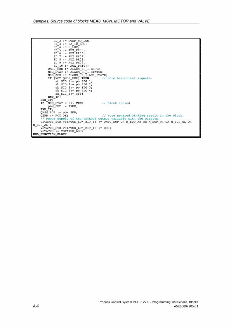
Samples: Source code of blocks MEAS_MON, MOTOR and VALVE
Process Control System PCS 7 V7.0 - Programming Instructions, Blocks A-6 A5E00807905-01
SD_2 := STEP_NO_LOC, SD_3 := BA_ID_LOC, SD_4 := U_LOC, SD_5 := AUX_PR05, SD_6 := AUX_PR06, SD_7 := AUX_PR07, SD_8 := AUX_PR08, SD_9 := AUX_PR09, SD_10 := AUX_PR10); QMSG_ERR := ALARM_8P_1.ERROR; MSG_STAT := ALARM_8P_1.STATUS; MSG_ACK := ALARM_8P_1.ACK_STATE; IF (NOT QMSG_ERR) THEN // Note historical signals. sb_SIG_1:= pb_SIG_1; sb_SIG_2:= pb_SIG_2; sb_SIG_3:= pb_SIG_3; sb_SIG_4:= pb_SIG_4; sb_SIG_5:= CSF; END_IF; END_IF; IF (MSG_STAT = 21) THEN // Block locked pbM_SUP := TRUE; END_IF; QMSG_SUP := pbM_SUP; QERR := NOT OK; // Note negated OK-Flag result in the block. // Power supply of the VSTATUS output variable with the outputs. VSTATUS_STR.VSTATUS_LOW_BIT_14 := QMSG_SUP OR M_SUP_AH OR M_SUP_WH OR M_SUP_WL OR M_SUP_AL ; VSTATUS_STR.VSTATUS_LOW_BIT_15 := OOS; VSTATUS := VSTATUS_LOC; END_FUNCTION_BLOCK
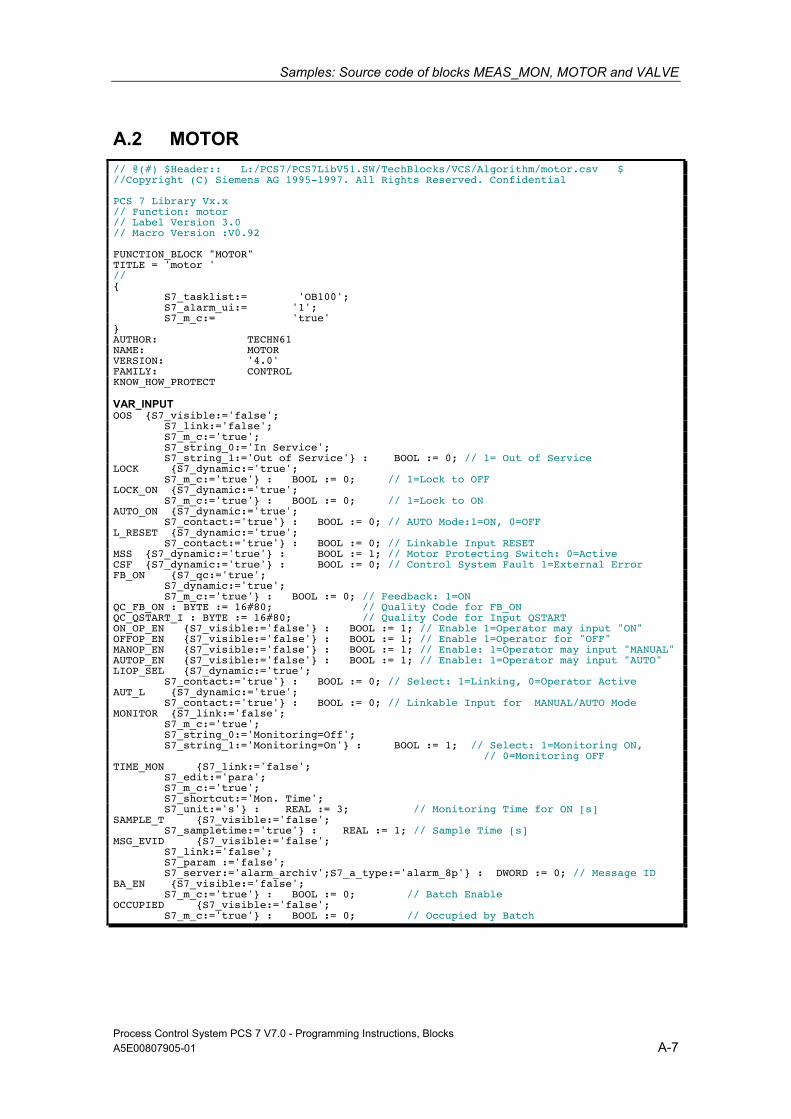
Samples: Source code of blocks MEAS_MON, MOTOR and VALVE
Process Control System PCS 7 V7.0 - Programming Instructions, Blocks A5E00807905-01 A-7
A.2 MOTOR // @(#) $Header:: L:/PCS7/PCS7LibV51.SW/TechBlocks/VCS/Algorithm/motor.csv $ //Copyright (C) Siemens AG 1995-1997. All Rights Reserved. Confidential PCS 7 Library Vx.x // Function: motor // Label Version 3.0 // Macro Version :V0.92 FUNCTION_BLOCK "MOTOR" TITLE = 'motor ' // { S7_tasklist:= 'OB100'; S7_alarm_ui:= '1'; S7_m_c:= 'true' } AUTHOR: TECHN61 NAME: MOTOR VERSION: '4.0' FAMILY: CONTROL KNOW_HOW_PROTECT VAR_INPUT OOS {S7_visible:='false'; S7_link:='false'; S7_m_c:='true'; S7_string_0:='In Service'; S7_string_1:='Out of Service'} : BOOL := 0; // 1= Out of Service LOCK {S7_dynamic:='true'; S7_m_c:='true'} : BOOL := 0; // 1=Lock to OFF LOCK_ON {S7_dynamic:='true'; S7_m_c:='true'} : BOOL := 0; // 1=Lock to ON AUTO_ON {S7_dynamic:='true'; S7_contact:='true'} : BOOL := 0; // AUTO Mode:1=ON, 0=OFF L_RESET {S7_dynamic:='true'; S7_contact:='true'} : BOOL := 0; // Linkable Input RESET MSS {S7_dynamic:='true'} : BOOL := 1; // Motor Protecting Switch: 0=Active CSF {S7_dynamic:='true'} : BOOL := 0; // Control System Fault 1=External Error FB_ON {S7_qc:='true'; S7_dynamic:='true'; S7_m_c:='true'} : BOOL := 0; // Feedback: 1=ON QC_FB_ON : BYTE := 16#80; // Quality Code for FB_ON QC_QSTART_I : BYTE := 16#80; // Quality Code for Input QSTART ON_OP_EN {S7_visible:='false'} : BOOL := 1; // Enable 1=Operator may input "ON" OFFOP_EN {S7_visible:='false'} : BOOL := 1; // Enable 1=Operator for "OFF" MANOP_EN {S7_visible:='false'} : BOOL := 1; // Enable: 1=Operator may input "MANUAL" AUTOP_EN {S7_visible:='false'} : BOOL := 1; // Enable: 1=Operator may input "AUTO" LIOP_SEL {S7_dynamic:='true'; S7_contact:='true'} : BOOL := 0; // Select: 1=Linking, 0=Operator Active AUT_L {S7_dynamic:='true'; S7_contact:='true'} : BOOL := 0; // Linkable Input for MANUAL/AUTO Mode MONITOR {S7_link:='false'; S7_m_c:='true'; S7_string_0:='Monitoring=Off'; S7_string_1:='Monitoring=On'} : BOOL := 1; // Select: 1=Monitoring ON, // 0=Monitoring OFF TIME_MON {S7_link:='false'; S7_edit:='para'; S7_m_c:='true'; S7_shortcut:='Mon. Time'; S7_unit:='s'} : REAL := 3; // Monitoring Time for ON [s] SAMPLE_T {S7_visible:='false'; S7_sampletime:='true'} : REAL := 1; // Sample Time [s] MSG_EVID {S7_visible:='false'; S7_link:='false'; S7_param :='false'; S7_server:='alarm_archiv';S7_a_type:='alarm_8p'} : DWORD := 0; // Message ID BA_EN {S7_visible:='false'; S7_m_c:='true'} : BOOL := 0; // Batch Enable OCCUPIED {S7_visible:='false'; S7_m_c:='true'} : BOOL := 0; // Occupied by Batch
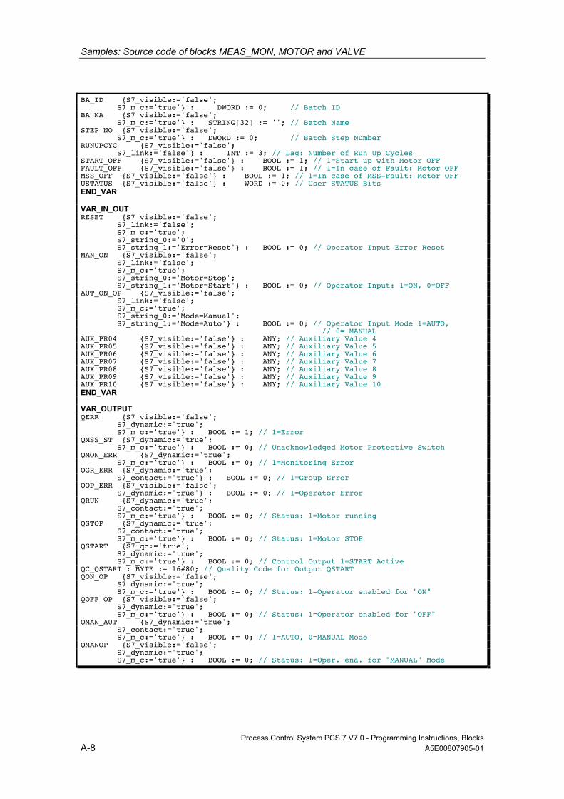
Samples: Source code of blocks MEAS_MON, MOTOR and VALVE
Process Control System PCS 7 V7.0 - Programming Instructions, Blocks A-8 A5E00807905-01
BA_ID {S7_visible:='false'; S7_m_c:='true'} : DWORD := 0; // Batch ID BA_NA {S7_visible:='false'; S7_m_c:='true'} : STRING[32] := ''; // Batch Name STEP_NO {S7_visible:='false'; S7_m_c:='true'} : DWORD := 0; // Batch Step Number RUNUPCYC {S7_visible:='false'; S7_link:='false'} : INT := 3; // Lag: Number of Run Up Cycles START_OFF {S7_visible:='false'} : BOOL := 1; // 1=Start up with Motor OFF FAULT_OFF {S7_visible:='false'} : BOOL := 1; // 1=In case of Fault: Motor OFF MSS_OFF {S7_visible:='false'} : BOOL := 1; // 1=In case of MSS-Fault: Motor OFF USTATUS {S7_visible:='false'} : WORD := 0; // User STATUS Bits END_VAR VAR_IN_OUT RESET {S7_visible:='false'; S7_link:='false'; S7_m_c:='true'; S7_string_0:='0'; S7_string_1:='Error=Reset'} : BOOL := 0; // Operator Input Error Reset MAN_ON {S7_visible:='false'; S7_link:='false'; S7_m_c:='true'; S7_string_0:='Motor=Stop'; S7_string_1:='Motor=Start'} : BOOL := 0; // Operator Input: 1=ON, 0=OFF AUT_ON_OP {S7_visible:='false'; S7_link:='false'; S7_m_c:='true'; S7_string_0:='Mode=Manual'; S7_string_1:='Mode=Auto'} : BOOL := 0; // Operator Input Mode 1=AUTO, // 0= MANUAL AUX_PR04 {S7_visible:='false'} : ANY; // Auxiliary Value 4 AUX_PR05 {S7_visible:='false'} : ANY; // Auxiliary Value 5 AUX_PR06 {S7_visible:='false'} : ANY; // Auxiliary Value 6 AUX_PR07 {S7_visible:='false'} : ANY; // Auxiliary Value 7 AUX_PR08 {S7_visible:='false'} : ANY; // Auxiliary Value 8 AUX_PR09 {S7_visible:='false'} : ANY; // Auxiliary Value 9 AUX_PR10 {S7_visible:='false'} : ANY; // Auxiliary Value 10 END_VAR VAR_OUTPUT QERR {S7_visible:='false'; S7_dynamic:='true'; S7_m_c:='true'} : BOOL := 1; // 1=Error QMSS_ST {S7_dynamic:='true'; S7_m_c:='true'} : BOOL := 0; // Unacknowledged Motor Protective Switch QMON_ERR {S7_dynamic:='true'; S7_m_c:='true'} : BOOL := 0; // 1=Monitoring Error QGR_ERR {S7_dynamic:='true'; S7_contact:='true'} : BOOL := 0; // 1=Group Error QOP_ERR {S7_visible:='false'; S7_dynamic:='true'} : BOOL := 0; // 1=Operator Error QRUN {S7_dynamic:='true'; S7_contact:='true'; S7_m_c:='true'} : BOOL := 0; // Status: 1=Motor running QSTOP {S7_dynamic:='true'; S7_contact:='true'; S7_m_c:='true'} : BOOL := 0; // Status: 1=Motor STOP QSTART {S7_qc:='true'; S7_dynamic:='true'; S7_m_c:='true'} : BOOL := 0; // Control Output 1=START Active QC_QSTART : BYTE := 16#80; // Quality Code for Output QSTART QON_OP {S7_visible:='false'; S7_dynamic:='true'; S7_m_c:='true'} : BOOL := 0; // Status: 1=Operator enabled for "ON" QOFF_OP {S7_visible:='false'; S7_dynamic:='true'; S7_m_c:='true'} : BOOL := 0; // Status: 1=Operator enabled for "OFF" QMAN_AUT {S7_dynamic:='true'; S7_contact:='true'; S7_m_c:='true'} : BOOL := 0; // 1=AUTO, 0=MANUAL Mode QMANOP {S7_visible:='false'; S7_dynamic:='true'; S7_m_c:='true'} : BOOL := 0; // Status: 1=Oper. ena. for "MANUAL" Mode
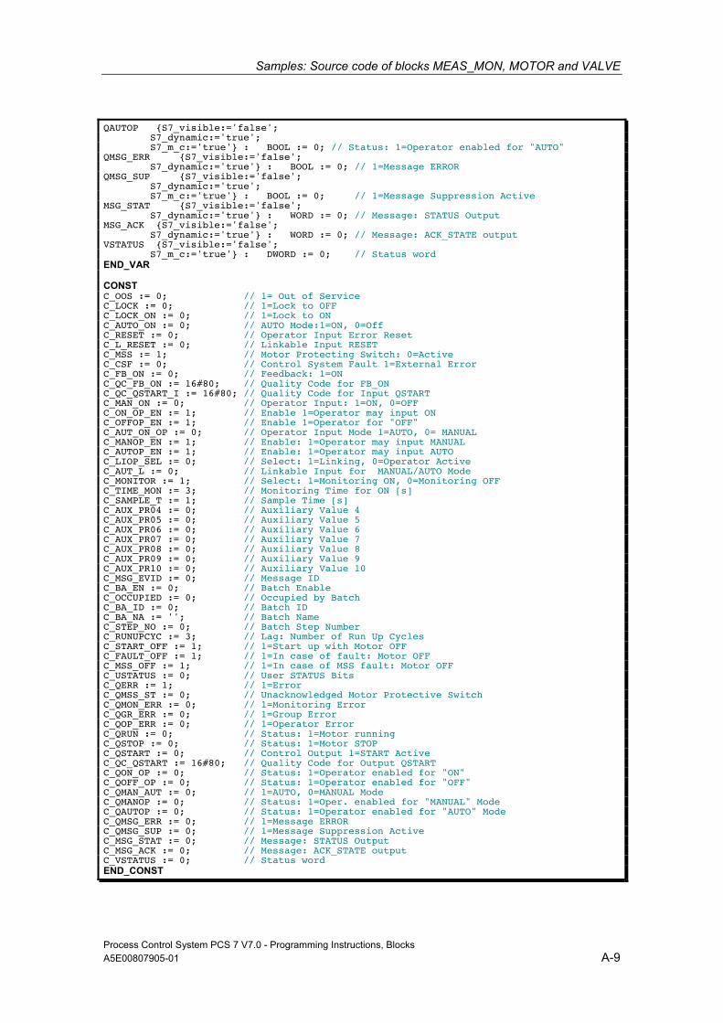
Samples: Source code of blocks MEAS_MON, MOTOR and VALVE
Process Control System PCS 7 V7.0 - Programming Instructions, Blocks A5E00807905-01 A-9
QAUTOP {S7_visible:='false'; S7_dynamic:='true'; S7_m_c:='true'} : BOOL := 0; // Status: 1=Operator enabled for "AUTO" QMSG_ERR {S7_visible:='false'; S7_dynamic:='true'} : BOOL := 0; // 1=Message ERROR QMSG_SUP {S7_visible:='false'; S7_dynamic:='true'; S7_m_c:='true'} : BOOL := 0; // 1=Message Suppression Active MSG_STAT {S7_visible:='false'; S7_dynamic:='true'} : WORD := 0; // Message: STATUS Output MSG_ACK {S7_visible:='false'; S7_dynamic:='true'} : WORD := 0; // Message: ACK_STATE output VSTATUS {S7_visible:='false'; S7_m_c:='true'} : DWORD := 0; // Status word END_VAR CONST C_OOS := 0; // 1= Out of Service C_LOCK := 0; // 1=Lock to OFF C_LOCK_ON := 0; // 1=Lock to ON C_AUTO_ON := 0; // AUTO Mode:1=ON, 0=Off C_RESET := 0; // Operator Input Error Reset C_L_RESET := 0; // Linkable Input RESET C_MSS := 1; // Motor Protecting Switch: 0=Active C_CSF := 0; // Control System Fault 1=External Error C_FB_ON := 0; // Feedback: 1=ON C_QC_FB_ON := 16#80; // Quality Code for FB_ON C_QC_QSTART_I := 16#80; // Quality Code for Input QSTART C_MAN_ON := 0; // Operator Input: 1=ON, 0=OFF C_ON_OP_EN := 1; // Enable 1=Operator may input ON C_OFFOP_EN := 1; // Enable 1=Operator for "OFF" C_AUT_ON_OP := 0; // Operator Input Mode 1=AUTO, 0= MANUAL C_MANOP_EN := 1; // Enable: 1=Operator may input MANUAL C_AUTOP_EN := 1; // Enable: 1=Operator may input AUTO C_LIOP_SEL := 0; // Select: 1=Linking, 0=Operator Active C_AUT_L := 0; // Linkable Input for MANUAL/AUTO Mode C_MONITOR := 1; // Select: 1=Monitoring ON, 0=Monitoring OFF C_TIME_MON := 3; // Monitoring Time for ON [s] C_SAMPLE_T := 1; // Sample Time [s] C_AUX_PR04 := 0; // Auxiliary Value 4 C_AUX_PR05 := 0; // Auxiliary Value 5 C_AUX_PR06 := 0; // Auxiliary Value 6 C_AUX_PR07 := 0; // Auxiliary Value 7 C_AUX_PR08 := 0; // Auxiliary Value 8 C_AUX_PR09 := 0; // Auxiliary Value 9 C_AUX_PR10 := 0; // Auxiliary Value 10 C_MSG_EVID := 0; // Message ID C_BA_EN := 0; // Batch Enable C_OCCUPIED := 0; // Occupied by Batch C_BA_ID := 0; // Batch ID C_BA_NA := ''; // Batch Name C_STEP_NO := 0; // Batch Step Number C_RUNUPCYC := 3; // Lag: Number of Run Up Cycles C_START_OFF := 1; // 1=Start up with Motor OFF C_FAULT_OFF := 1; // 1=In case of fault: Motor OFF C_MSS_OFF := 1; // 1=In case of MSS fault: Motor OFF C_USTATUS := 0; // User STATUS Bits C_QERR := 1; // 1=Error C_QMSS_ST := 0; // Unacknowledged Motor Protective Switch C_QMON_ERR := 0; // 1=Monitoring Error C_QGR_ERR := 0; // 1=Group Error C_QOP_ERR := 0; // 1=Operator Error C_QRUN := 0; // Status: 1=Motor running C_QSTOP := 0; // Status: 1=Motor STOP C_QSTART := 0; // Control Output 1=START Active C_QC_QSTART := 16#80; // Quality Code for Output QSTART C_QON_OP := 0; // Status: 1=Operator enabled for "ON" C_QOFF_OP := 0; // Status: 1=Operator enabled for "OFF" C_QMAN_AUT := 0; // 1=AUTO, 0=MANUAL Mode C_QMANOP := 0; // Status: 1=Oper. enabled for "MANUAL" Mode C_QAUTOP := 0; // Status: 1=Operator enabled for "AUTO" Mode C_QMSG_ERR := 0; // 1=Message ERROR C_QMSG_SUP := 0; // 1=Message Suppression Active C_MSG_STAT := 0; // Message: STATUS Output C_MSG_ACK := 0; // Message: ACK_STATE output C_VSTATUS := 0; // Status word END_CONST
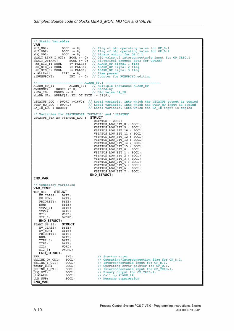
Samples: Source code of blocks MEAS_MON, MOTOR and VALVE
Process Control System PCS 7 V7.0 - Programming Instructions, Blocks A-10 A5E00807905-01
// Static Variables VAR sbI_OD1: BOOL := 0; // Flag of old operating value for OP_D.1 sbI_OD2: BOOL := 0; // Flag of old operating value for OP_D.2 sbQ_OD1: BOOL := 0; // Binary output for OP_D.1 sbALT_LINK_I_OT1: BOOL := 0; // Old value of interconnectable input for OP_TRIG.1 sbALT_QSTART: BOOL := 0; // Historical process data for QSTART sb_SIG_1: BOOL := FALSE; // ALARM_8P signal 1 flag sb_SIG_2: BOOL := FALSE; // ALARM_8P signal 2 flag sb_SIG_3: BOOL := FALSE; // ALARM_8P signal 3 flag srAktZeit: REAL := 0; // Time passed siRUNUPCNT: INT := 0; // Counter for RUNUPCYC editing //------------------------ ALARM_8P.1 ----------------------------- ALARM_8P_1: ALARM_8P; // Multiple instanced ALARM_8P dwDUMMY: DWORD := 0; // Stand-by siBA_ID: DWORD := 0; // Old value BA_ID sbyBA_NA: ARRAY[1..32] OF BYTE := 32(0); VSTATUS_LOC : DWORD :=16#0; // Local variable, into which the VSTATUS output is copied STEP_NO_LOC : DWORD; // Local variable, into which the STEP_NO input is copied BA_ID_LOC : DWORD; // Local variable, into which the BA_ID input is copied // Variables for STATUSWORT "VSTATUS" and "USTATUS" VSTATUS_STR AT VSTATUS_LOC : STRUCT USTATUS : WORD; VSTATUS_LOW_BIT_8 : BOOL; VSTATUS_LOW_BIT_9 : BOOL; VSTATUS_LOW_BIT_10 : BOOL; VSTATUS_LOW_BIT_11 : BOOL; VSTATUS_LOW_BIT_12 : BOOL; VSTATUS_LOW_BIT_13 : BOOL; VSTATUS_LOW_BIT_14 : BOOL; VSTATUS_LOW_BIT_15 : BOOL; VSTATUS_LOW_BIT_0 : BOOL; VSTATUS_LOW_BIT_1 : BOOL; VSTATUS_LOW_BIT_2 : BOOL; VSTATUS_LOW_BIT_3 : BOOL; VSTATUS_LOW_BIT_4 : BOOL; VSTATUS_LOW_BIT_5 : BOOL; VSTATUS_LOW_BIT_6 : BOOL; VSTATUS_LOW_BIT_7 : BOOL; END_STRUCT; END_VAR // Temporary variables VAR_TEMP TOP_SI: STRUCT EV_CLASS: BYTE; EV_NUM: BYTE; PRIORITY: BYTE; NUM: BYTE; TYP2_3: BYTE; TYP1: BYTE; ZI1: WORD; ZI2_3: DWORD; END_STRUCT; START_UP_SI: STRUCT EV_CLASS: BYTE; EV_NUM: BYTE; PRIORITY: BYTE; NUM: BYTE; TYP2_3: BYTE; TYP1: BYTE; ZI1: WORD; ZI2_3: DWORD; END_STRUCT; ERR : INT; // Startup error pbLINK_ON_OD1: BOOL; // Operating/Interconnection flag for OP_D.1. pbLINK_I_OD1: BOOL; // Interconnectable input for OP_D.1. pbQOP_ERR: BOOL; // Operating error pointer for OP_D.1. pbLINK_I_OT1: BOOL; // Interconnectable input for OP_TRIG.1. pbQ_OT1: BOOL; // Binary output for OP_TRIG.1. pbALARM: BOOL; // Call up ALARM_8P pbM_SUP: BOOL; // Message suppression END_VAR
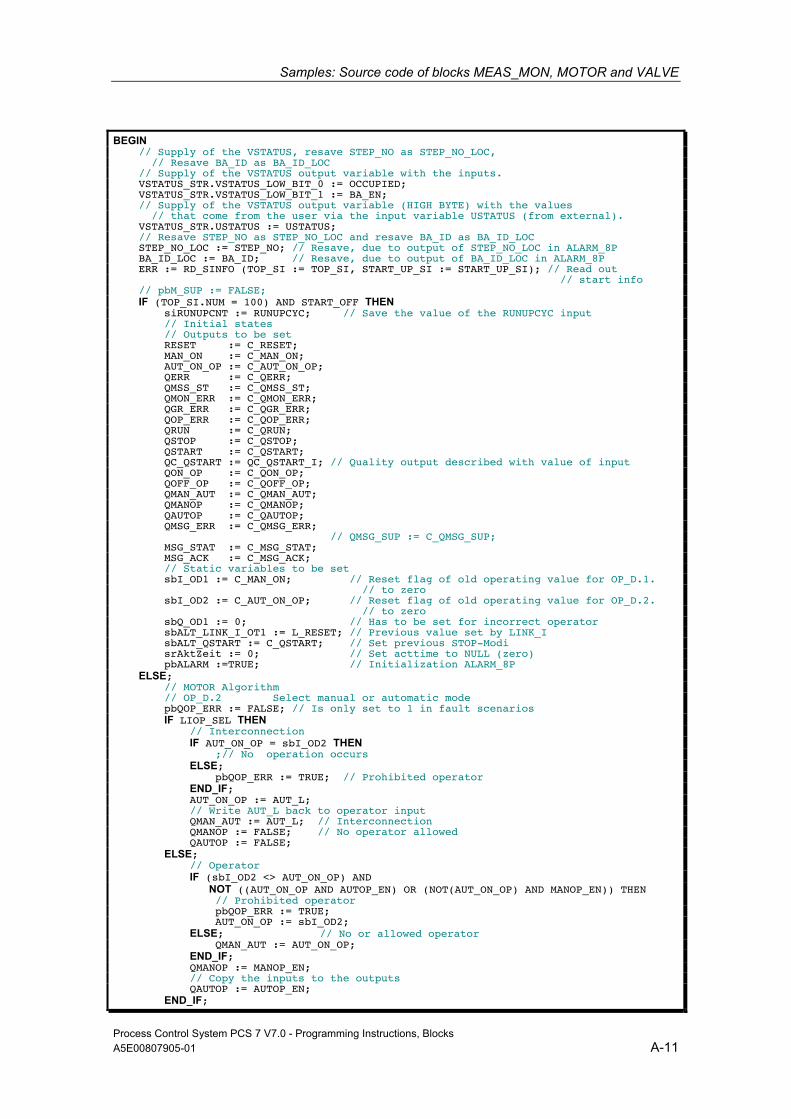
Samples: Source code of blocks MEAS_MON, MOTOR and VALVE
Process Control System PCS 7 V7.0 - Programming Instructions, Blocks A5E00807905-01 A-11
BEGIN // Supply of the VSTATUS, resave STEP_NO as STEP_NO_LOC, // Resave BA_ID as BA_ID_LOC // Supply of the VSTATUS output variable with the inputs. VSTATUS_STR.VSTATUS_LOW_BIT_0 := OCCUPIED; VSTATUS_STR.VSTATUS_LOW_BIT_1 := BA_EN; // Supply of the VSTATUS output variable (HIGH BYTE) with the values // that come from the user via the input variable USTATUS (from external). VSTATUS_STR.USTATUS := USTATUS; // Resave STEP_NO as STEP_NO_LOC and resave BA_ID as BA_ID_LOC STEP_NO_LOC := STEP_NO; // Resave, due to output of STEP_NO_LOC in ALARM_8P BA_ID_LOC := BA_ID; // Resave, due to output of BA_ID_LOC in ALARM_8P ERR := RD_SINFO (TOP_SI := TOP_SI, START_UP_SI := START_UP_SI); // Read out // start info // pbM_SUP := FALSE; IF (TOP_SI.NUM = 100) AND START_OFF THEN siRUNUPCNT := RUNUPCYC; // Save the value of the RUNUPCYC input // Initial states // Outputs to be set RESET := C_RESET; MAN_ON := C_MAN_ON; AUT_ON_OP := C_AUT_ON_OP; QERR := C_QERR; QMSS_ST := C_QMSS_ST; QMON_ERR := C_QMON_ERR; QGR_ERR := C_QGR_ERR; QOP_ERR := C_QOP_ERR; QRUN := C_QRUN; QSTOP := C_QSTOP; QSTART := C_QSTART; QC_QSTART := QC_QSTART_I; // Quality output described with value of input QON_OP := C_QON_OP; QOFF_OP := C_QOFF_OP; QMAN_AUT := C_QMAN_AUT; QMANOP := C_QMANOP; QAUTOP := C_QAUTOP; QMSG_ERR := C_QMSG_ERR; // QMSG_SUP := C_QMSG_SUP; MSG_STAT := C_MSG_STAT; MSG_ACK := C_MSG_ACK; // Static variables to be set sbI_OD1 := C_MAN_ON; // Reset flag of old operating value for OP_D.1. // to zero sbI_OD2 := C_AUT_ON_OP; // Reset flag of old operating value for OP_D.2. // to zero sbQ_OD1 := 0; // Has to be set for incorrect operator sbALT_LINK_I_OT1 := L_RESET; // Previous value set by LINK_I sbALT_QSTART := C_QSTART; // Set previous STOP-Modi srAktZeit := 0; // Set acttime to NULL (zero) pbALARM :=TRUE; // Initialization ALARM_8P ELSE; // MOTOR Algorithm // OP_D.2 Select manual or automatic mode pbQOP_ERR := FALSE; // Is only set to 1 in fault scenarios IF LIOP_SEL THEN // Interconnection IF AUT_ON_OP = sbI_OD2 THEN ;// No operation occurs ELSE; pbQOP_ERR := TRUE; // Prohibited operator END_IF; AUT_ON_OP := AUT_L; // Write AUT_L back to operator input QMAN_AUT := AUT_L; // Interconnection QMANOP := FALSE; // No operator allowed QAUTOP := FALSE; ELSE; // Operator IF (sbI_OD2 <> AUT_ON_OP) AND NOT ((AUT_ON_OP AND AUTOP_EN) OR (NOT(AUT_ON_OP) AND MANOP_EN)) THEN // Prohibited operator pbQOP_ERR := TRUE; AUT_ON_OP := sbI_OD2; ELSE; // No or allowed operator QMAN_AUT := AUT_ON_OP; END_IF; QMANOP := MANOP_EN; // Copy the inputs to the outputs QAUTOP := AUTOP_EN; END_IF;
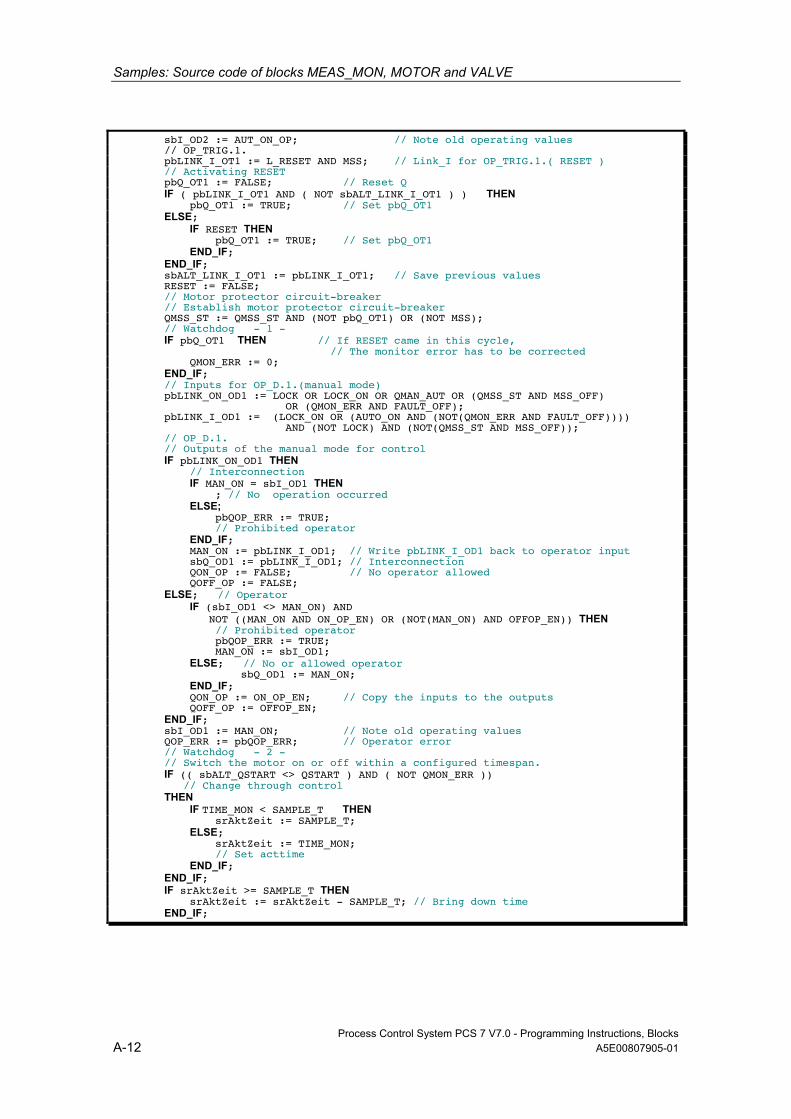
Samples: Source code of blocks MEAS_MON, MOTOR and VALVE
Process Control System PCS 7 V7.0 - Programming Instructions, Blocks A-12 A5E00807905-01
sbI_OD2 := AUT_ON_OP; // Note old operating values // OP_TRIG.1. pbLINK_I_OT1 := L_RESET AND MSS; // Link_I for OP_TRIG.1.( RESET ) // Activating RESET pbQ_OT1 := FALSE; // Reset Q IF ( pbLINK_I_OT1 AND ( NOT sbALT_LINK_I_OT1 ) ) THEN pbQ_OT1 := TRUE; // Set pbQ_OT1 ELSE; IF RESET THEN pbQ_OT1 := TRUE; // Set pbQ_OT1 END_IF; END_IF; sbALT_LINK_I_OT1 := pbLINK_I_OT1; // Save previous values RESET := FALSE; // Motor protector circuit-breaker // Establish motor protector circuit-breaker QMSS_ST := QMSS_ST AND (NOT pbQ_OT1) OR (NOT MSS); // Watchdog - 1 - IF pbQ_OT1 THEN // If RESET came in this cycle, // The monitor error has to be corrected QMON_ERR := 0; END_IF; // Inputs for OP_D.1.(manual mode) pbLINK_ON_OD1 := LOCK OR LOCK_ON OR QMAN_AUT OR (QMSS_ST AND MSS_OFF) OR (QMON_ERR AND FAULT_OFF); pbLINK_I_OD1 := (LOCK_ON OR (AUTO_ON AND (NOT(QMON_ERR AND FAULT_OFF)))) AND (NOT LOCK) AND (NOT(QMSS_ST AND MSS_OFF)); // OP_D.1. // Outputs of the manual mode for control IF pbLINK_ON_OD1 THEN // Interconnection IF MAN_ON = sbI_OD1 THEN ; // No operation occurred ELSE; pbQOP_ERR := TRUE; // Prohibited operator END_IF; MAN_ON := pbLINK_I_OD1; // Write pbLINK_I_OD1 back to operator input sbQ_OD1 := pbLINK_I_OD1; // Interconnection QON_OP := FALSE; // No operator allowed QOFF_OP := FALSE; ELSE; // Operator IF (sbI_OD1 <> MAN_ON) AND NOT ((MAN_ON AND ON_OP_EN) OR (NOT(MAN_ON) AND OFFOP_EN)) THEN // Prohibited operator pbQOP_ERR := TRUE; MAN_ON := sbI_OD1; ELSE; // No or allowed operator sbQ_OD1 := MAN_ON; END_IF; QON_OP := ON_OP_EN; // Copy the inputs to the outputs QOFF_OP := OFFOP_EN; END_IF; sbI_OD1 := MAN_ON; // Note old operating values QOP_ERR := pbQOP_ERR; // Operator error // Watchdog - 2 - // Switch the motor on or off within a configured timespan. IF (( sbALT_QSTART <> QSTART ) AND ( NOT QMON_ERR )) // Change through control THEN IF TIME_MON < SAMPLE_T THEN srAktZeit := SAMPLE_T; ELSE; srAktZeit := TIME_MON; // Set acttime END_IF; END_IF; IF srAktZeit >= SAMPLE_T THEN srAktZeit := srAktZeit - SAMPLE_T; // Bring down time END_IF;
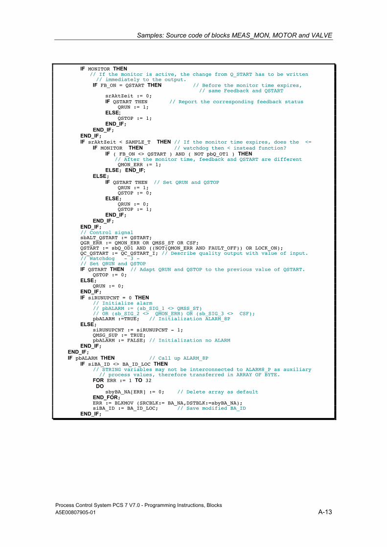
Samples: Source code of blocks MEAS_MON, MOTOR and VALVE
Process Control System PCS 7 V7.0 - Programming Instructions, Blocks A5E00807905-01 A-13
IF MONITOR THEN // If the monitor is active, the change from Q_START has to be written // immediately to the output. IF FB_ON = QSTART THEN // Before the monitor time expires, // same Feedback and QSTART srAktZeit := 0; IF QSTART THEN // Report the corresponding feedback status QRUN := 1; ELSE; QSTOP := 1; END_IF; END_IF; END_IF; IF srAktZeit < SAMPLE_T THEN // If the monitor time expires, does the <= IF MONITOR THEN // watchdog then < instead function? IF ( FB_ON <> QSTART ) AND ( NOT pbQ_OT1 ) THEN // After the monitor time, feedback and QSTART are different QMON_ERR := 1; ELSE; END_IF; ELSE; IF QSTART THEN // Set QRUN and QSTOP QRUN := 1; QSTOP := 0; ELSE; QRUN := 0; QSTOP := 1; END_IF; END_IF; END_IF; // Control signal sbALT_QSTART := QSTART; QGR_ERR := QMON_ERR OR QMSS_ST OR CSF; QSTART := sbQ_OD1 AND ((NOT(QMON_ERR AND FAULT_OFF)) OR LOCK_ON); QC_QSTART := QC_QSTART_I; // Describe quality output with value of input. // Watchdog - 3 - // Set QRUN and QSTOP IF QSTART THEN // Adapt QRUN and QSTOP to the previous value of QSTART. QSTOP := 0; ELSE; QRUN := 0; END_IF; IF siRUNUPCNT = 0 THEN // Initialize alarm // pbALARM := (sb_SIG_1 <> QMSS_ST) // OR (sb_SIG_2 <> QMON_ERR) OR (sb_SIG_3 <> CSF); pbALARM :=TRUE; // Initialization ALARM_8P ELSE; siRUNUPCNT := siRUNUPCNT - 1; QMSG_SUP := TRUE; pbALARM := FALSE; // Initialization no ALARM END_IF; END_IF; IF pbALARM THEN // Call up ALARM_8P IF siBA_ID <> BA_ID_LOC THEN // STRING variables may not be interconnected to ALARM8_P as auxiliary // process values, therefore transferred in ARRAY OF BYTE. FOR ERR := 1 TO 32 DO sbyBA_NA[ERR] := 0; // Delete array as default END_FOR; ERR := BLKMOV (SRCBLK:= BA_NA,DSTBLK:=sbyBA_NA); siBA_ID := BA_ID_LOC; // Save modified BA_ID END_IF;
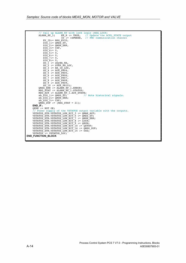
Samples: Source code of blocks MEAS_MON, MOTOR and VALVE
Process Control System PCS 7 V7.0 - Programming Instructions, Blocks A-14 A5E00807905-01
// Call up ALARM_8P with lock logic (MSG_LOCK) ALARM_8P_1( EN_R := TRUE, // Update the ACKL_STATE output ID := 16#EEEE, // PMC communication channel EV_ID:= MSG_EVID, SIG_1:= QMSS_ST, SIG_2:= QMON_ERR, SIG_3:= CSF, SIG_4:= 0, SIG_5:= 0, SIG_6:= 0, SIG_7:= 0, SIG_8:= 0, SD_1 := sbyBA_NA, SD_2 := STEP_NO_LOC, SD_3 := BA_ID_LOC, SD_4 := AUX_PR04, SD_5 := AUX_PR05, SD_6 := AUX_PR06, SD_7 := AUX_PR07, SD_8 := AUX_PR08, SD_9 := AUX_PR09, SD_10 := AUX_PR10); QMSG_ERR := ALARM_8P_1.ERROR; MSG_STAT := ALARM_8P_1.STATUS; MSG_ACK := ALARM_8P_1.ACK_STATE; sb_SIG_1:= QMSS_ST; // Note historical signals. sb_SIG_2:= QMON_ERR; sb_SIG_3:= CSF; QMSG_SUP := (MSG_STAT = 21); END_IF; QERR := NOT OK; // Power supply of the VSTATUS output variable with the outputs. VSTATUS_STR.VSTATUS_LOW_BIT_3 := QMAN_AUT; VSTATUS_STR.VSTATUS_LOW_BIT_5 := QMSS_ST; VSTATUS_STR.VSTATUS_LOW_BIT_7 := QMON_ERR; VSTATUS_STR.VSTATUS_LOW_BIT_8 := LOCK; VSTATUS_STR.VSTATUS_LOW_BIT_9 := QRUN; VSTATUS_STR.VSTATUS_LOW_BIT_10 := QSTOP; VSTATUS_STR.VSTATUS_LOW_BIT_14 := QMSG_SUP; VSTATUS_STR.VSTATUS_LOW_BIT_15 := OOS; VSTATUS := VSTATUS_LOC; END_FUNCTION_BLOCK
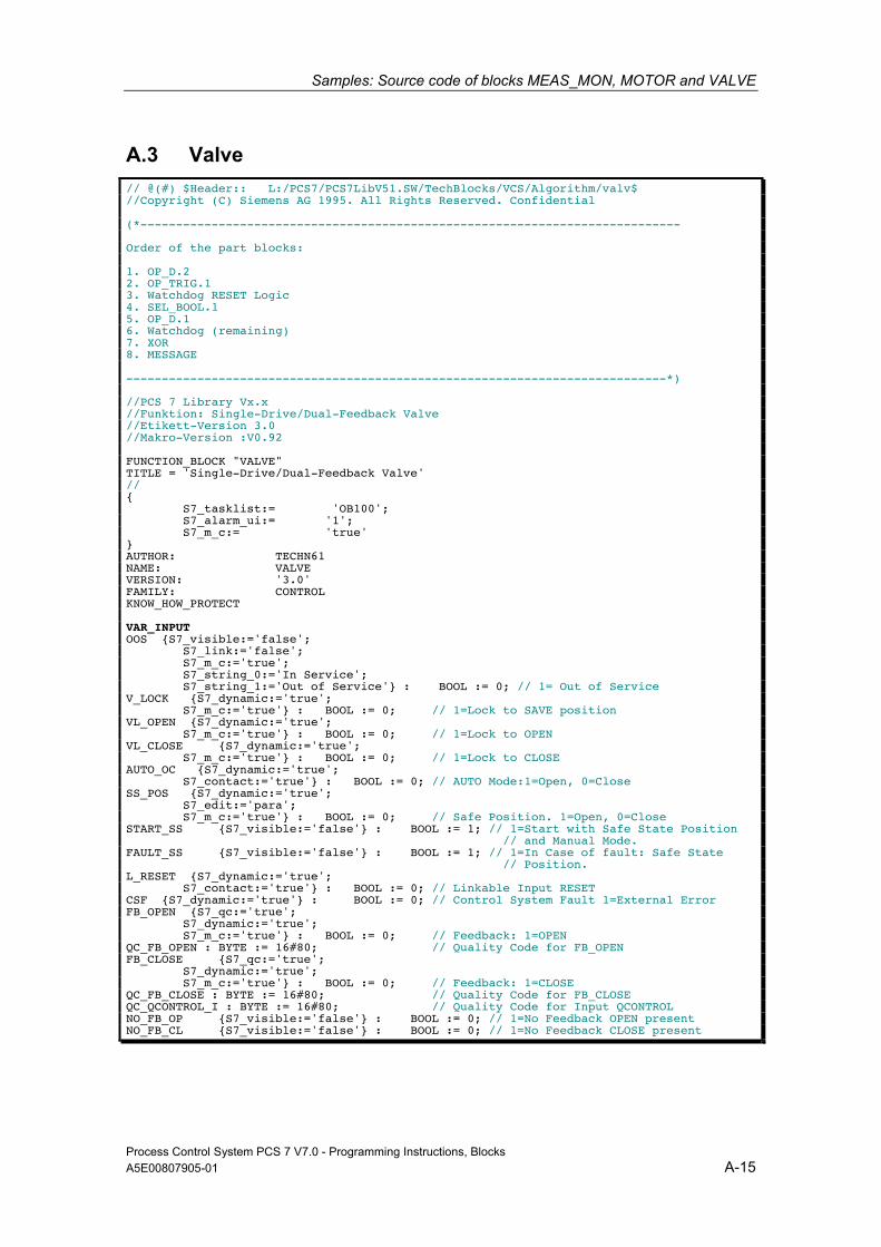
Samples: Source code of blocks MEAS_MON, MOTOR and VALVE
Process Control System PCS 7 V7.0 - Programming Instructions, Blocks A5E00807905-01 A-15
A.3 Valve // @(#) $Header:: L:/PCS7/PCS7LibV51.SW/TechBlocks/VCS/Algorithm/valv$ //Copyright (C) Siemens AG 1995. All Rights Reserved. Confidential (*---------------------------------------------------------------------------- Order of the part blocks: 1. OP_D.2 2. OP_TRIG.1 3. Watchdog RESET Logic 4. SEL_BOOL.1 5. OP_D.1 6. Watchdog (remaining) 7. XOR 8. MESSAGE ----------------------------------------------------------------------------*) //PCS 7 Library Vx.x //Funktion: Single-Drive/Dual-Feedback Valve //Etikett-Version 3.0 //Makro-Version :V0.92 FUNCTION_BLOCK "VALVE" TITLE = 'Single-Drive/Dual-Feedback Valve' // { S7_tasklist:= 'OB100'; S7_alarm_ui:= '1'; S7_m_c:= 'true' } AUTHOR: TECHN61 NAME: VALVE VERSION: '3.0' FAMILY: CONTROL KNOW_HOW_PROTECT VAR_INPUT OOS {S7_visible:='false'; S7_link:='false'; S7_m_c:='true'; S7_string_0:='In Service'; S7_string_1:='Out of Service'} : BOOL := 0; // 1= Out of Service V_LOCK {S7_dynamic:='true'; S7_m_c:='true'} : BOOL := 0; // 1=Lock to SAVE position VL_OPEN {S7_dynamic:='true'; S7_m_c:='true'} : BOOL := 0; // 1=Lock to OPEN VL_CLOSE {S7_dynamic:='true'; S7_m_c:='true'} : BOOL := 0; // 1=Lock to CLOSE AUTO_OC {S7_dynamic:='true'; S7_contact:='true'} : BOOL := 0; // AUTO Mode:1=Open, 0=Close SS_POS {S7_dynamic:='true'; S7_edit:='para'; S7_m_c:='true'} : BOOL := 0; // Safe Position. 1=Open, 0=Close START_SS {S7_visible:='false'} : BOOL := 1; // 1=Start with Safe State Position // and Manual Mode. FAULT_SS {S7_visible:='false'} : BOOL := 1; // 1=In Case of fault: Safe State // Position. L_RESET {S7_dynamic:='true'; S7_contact:='true'} : BOOL := 0; // Linkable Input RESET CSF {S7_dynamic:='true'} : BOOL := 0; // Control System Fault 1=External Error FB_OPEN {S7_qc:='true'; S7_dynamic:='true'; S7_m_c:='true'} : BOOL := 0; // Feedback: 1=OPEN QC_FB_OPEN : BYTE := 16#80; // Quality Code for FB_OPEN FB_CLOSE {S7_qc:='true'; S7_dynamic:='true'; S7_m_c:='true'} : BOOL := 0; // Feedback: 1=CLOSE QC_FB_CLOSE : BYTE := 16#80; // Quality Code for FB_CLOSE QC_QCONTROL_I : BYTE := 16#80; // Quality Code for Input QCONTROL NO_FB_OP {S7_visible:='false'} : BOOL := 0; // 1=No Feedback OPEN present NO_FB_CL {S7_visible:='false'} : BOOL := 0; // 1=No Feedback CLOSE present
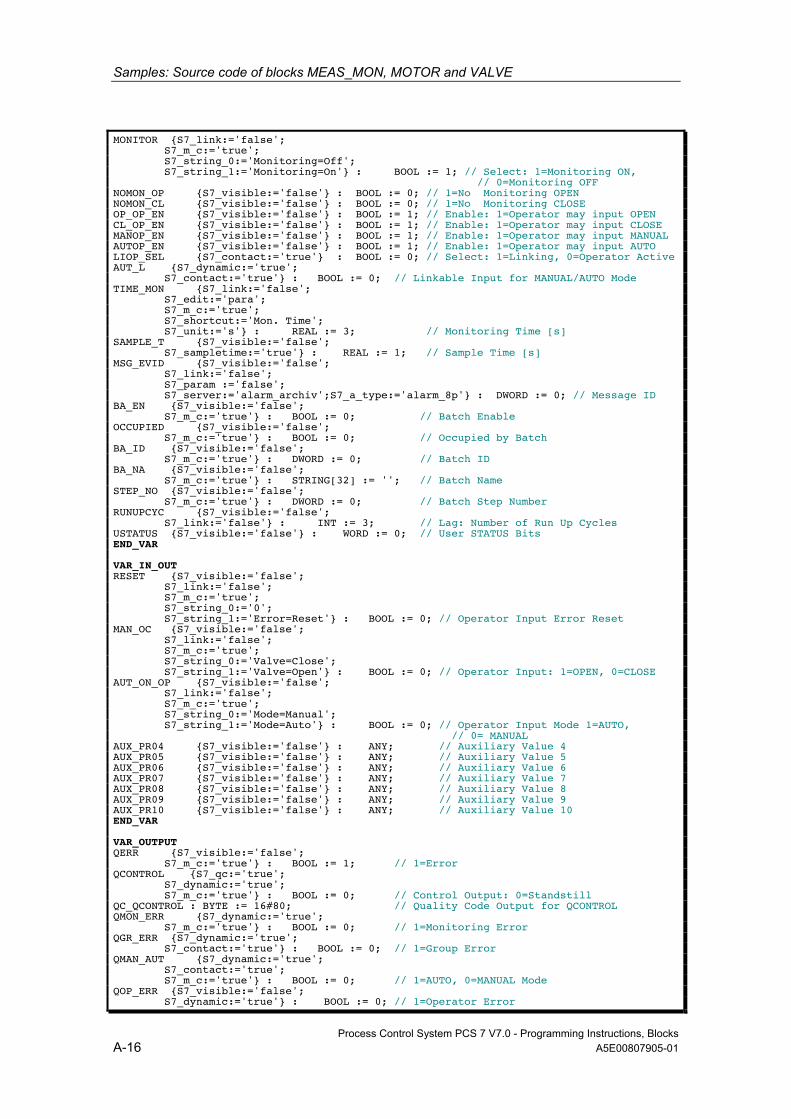
Samples: Source code of blocks MEAS_MON, MOTOR and VALVE
Process Control System PCS 7 V7.0 - Programming Instructions, Blocks A-16 A5E00807905-01
MONITOR {S7_link:='false'; S7_m_c:='true'; S7_string_0:='Monitoring=Off'; S7_string_1:='Monitoring=On'} : BOOL := 1; // Select: 1=Monitoring ON, // 0=Monitoring OFF NOMON_OP {S7_visible:='false'} : BOOL := 0; // 1=No Monitoring OPEN NOMON_CL {S7_visible:='false'} : BOOL := 0; // 1=No Monitoring CLOSE OP_OP_EN {S7_visible:='false'} : BOOL := 1; // Enable: 1=Operator may input OPEN CL_OP_EN {S7_visible:='false'} : BOOL := 1; // Enable: 1=Operator may input CLOSE MANOP_EN {S7_visible:='false'} : BOOL := 1; // Enable: 1=Operator may input MANUAL AUTOP_EN {S7_visible:='false'} : BOOL := 1; // Enable: 1=Operator may input AUTO LIOP_SEL {S7_contact:='true'} : BOOL := 0; // Select: 1=Linking, 0=Operator Active AUT_L {S7_dynamic:='true'; S7_contact:='true'} : BOOL := 0; // Linkable Input for MANUAL/AUTO Mode TIME_MON {S7_link:='false'; S7_edit:='para'; S7_m_c:='true'; S7_shortcut:='Mon. Time'; S7_unit:='s'} : REAL := 3; // Monitoring Time [s] SAMPLE_T {S7_visible:='false'; S7_sampletime:='true'} : REAL := 1; // Sample Time [s] MSG_EVID {S7_visible:='false'; S7_link:='false'; S7_param :='false'; S7_server:='alarm_archiv';S7_a_type:='alarm_8p'} : DWORD := 0; // Message ID BA_EN {S7_visible:='false'; S7_m_c:='true'} : BOOL := 0; // Batch Enable OCCUPIED {S7_visible:='false'; S7_m_c:='true'} : BOOL := 0; // Occupied by Batch BA_ID {S7_visible:='false'; S7_m_c:='true'} : DWORD := 0; // Batch ID BA_NA {S7_visible:='false'; S7_m_c:='true'} : STRING[32] := ''; // Batch Name STEP_NO {S7_visible:='false'; S7_m_c:='true'} : DWORD := 0; // Batch Step Number RUNUPCYC {S7_visible:='false'; S7_link:='false'} : INT := 3; // Lag: Number of Run Up Cycles USTATUS {S7_visible:='false'} : WORD := 0; // User STATUS Bits END_VAR VAR_IN_OUT RESET {S7_visible:='false'; S7_link:='false'; S7_m_c:='true'; S7_string_0:='0'; S7_string_1:='Error=Reset'} : BOOL := 0; // Operator Input Error Reset MAN_OC {S7_visible:='false'; S7_link:='false'; S7_m_c:='true'; S7_string_0:='Valve=Close'; S7_string_1:='Valve=Open'} : BOOL := 0; // Operator Input: 1=OPEN, 0=CLOSE AUT_ON_OP {S7_visible:='false'; S7_link:='false'; S7_m_c:='true'; S7_string_0:='Mode=Manual'; S7_string_1:='Mode=Auto'} : BOOL := 0; // Operator Input Mode 1=AUTO, // 0= MANUAL AUX_PR04 {S7_visible:='false'} : ANY; // Auxiliary Value 4 AUX_PR05 {S7_visible:='false'} : ANY; // Auxiliary Value 5 AUX_PR06 {S7_visible:='false'} : ANY; // Auxiliary Value 6 AUX_PR07 {S7_visible:='false'} : ANY; // Auxiliary Value 7 AUX_PR08 {S7_visible:='false'} : ANY; // Auxiliary Value 8 AUX_PR09 {S7_visible:='false'} : ANY; // Auxiliary Value 9 AUX_PR10 {S7_visible:='false'} : ANY; // Auxiliary Value 10 END_VAR VAR_OUTPUT QERR {S7_visible:='false'; S7_m_c:='true'} : BOOL := 1; // 1=Error QCONTROL {S7_qc:='true'; S7_dynamic:='true'; S7_m_c:='true'} : BOOL := 0; // Control Output: 0=Standstill QC_QCONTROL : BYTE := 16#80; // Quality Code Output for QCONTROL QMON_ERR {S7_dynamic:='true'; S7_m_c:='true'} : BOOL := 0; // 1=Monitoring Error QGR_ERR {S7_dynamic:='true'; S7_contact:='true'} : BOOL := 0; // 1=Group Error QMAN_AUT {S7_dynamic:='true'; S7_contact:='true'; S7_m_c:='true'} : BOOL := 0; // 1=AUTO, 0=MANUAL Mode QOP_ERR {S7_visible:='false'; S7_dynamic:='true'} : BOOL := 0; // 1=Operator Error
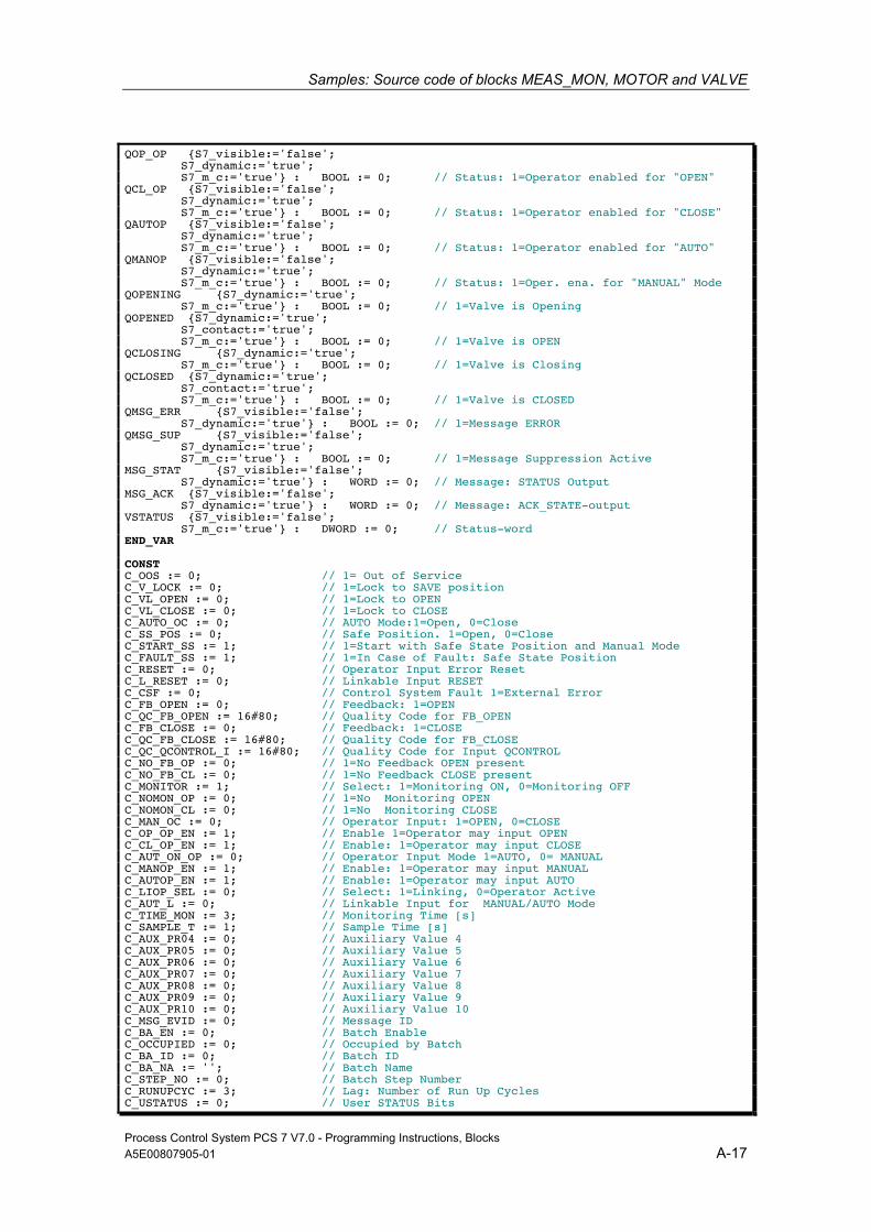
Samples: Source code of blocks MEAS_MON, MOTOR and VALVE
Process Control System PCS 7 V7.0 - Programming Instructions, Blocks A5E00807905-01 A-17
QOP_OP {S7_visible:='false'; S7_dynamic:='true'; S7_m_c:='true'} : BOOL := 0; // Status: 1=Operator enabled for "OPEN" QCL_OP {S7_visible:='false'; S7_dynamic:='true'; S7_m_c:='true'} : BOOL := 0; // Status: 1=Operator enabled for "CLOSE" QAUTOP {S7_visible:='false'; S7_dynamic:='true'; S7_m_c:='true'} : BOOL := 0; // Status: 1=Operator enabled for "AUTO" QMANOP {S7_visible:='false'; S7_dynamic:='true'; S7_m_c:='true'} : BOOL := 0; // Status: 1=Oper. ena. for "MANUAL" Mode QOPENING {S7_dynamic:='true'; S7_m_c:='true'} : BOOL := 0; // 1=Valve is Opening QOPENED {S7_dynamic:='true'; S7_contact:='true'; S7_m_c:='true'} : BOOL := 0; // 1=Valve is OPEN QCLOSING {S7_dynamic:='true'; S7_m_c:='true'} : BOOL := 0; // 1=Valve is Closing QCLOSED {S7_dynamic:='true'; S7_contact:='true'; S7_m_c:='true'} : BOOL := 0; // 1=Valve is CLOSED QMSG_ERR {S7_visible:='false'; S7_dynamic:='true'} : BOOL := 0; // 1=Message ERROR QMSG_SUP {S7_visible:='false'; S7_dynamic:='true'; S7_m_c:='true'} : BOOL := 0; // 1=Message Suppression Active MSG_STAT {S7_visible:='false'; S7_dynamic:='true'} : WORD := 0; // Message: STATUS Output MSG_ACK {S7_visible:='false'; S7_dynamic:='true'} : WORD := 0; // Message: ACK_STATE-output VSTATUS {S7_visible:='false'; S7_m_c:='true'} : DWORD := 0; // Status-word END_VAR CONST C_OOS := 0; // 1= Out of Service C_V_LOCK := 0; // 1=Lock to SAVE position C_VL_OPEN := 0; // 1=Lock to OPEN C_VL_CLOSE := 0; // 1=Lock to CLOSE C_AUTO_OC := 0; // AUTO Mode:1=Open, 0=Close C_SS_POS := 0; // Safe Position. 1=Open, 0=Close C_START_SS := 1; // 1=Start with Safe State Position and Manual Mode C_FAULT_SS := 1; // 1=In Case of Fault: Safe State Position C_RESET := 0; // Operator Input Error Reset C_L_RESET := 0; // Linkable Input RESET C_CSF := 0; // Control System Fault 1=External Error C_FB_OPEN := 0; // Feedback: 1=OPEN C_QC_FB_OPEN := 16#80; // Quality Code for FB_OPEN C_FB_CLOSE := 0; // Feedback: 1=CLOSE C_QC_FB_CLOSE := 16#80; // Quality Code for FB_CLOSE C_QC_QCONTROL_I := 16#80; // Quality Code for Input QCONTROL C_NO_FB_OP := 0; // 1=No Feedback OPEN present C_NO_FB_CL := 0; // 1=No Feedback CLOSE present C_MONITOR := 1; // Select: 1=Monitoring ON, 0=Monitoring OFF C_NOMON_OP := 0; // 1=No Monitoring OPEN C_NOMON_CL := 0; // 1=No Monitoring CLOSE C_MAN_OC := 0; // Operator Input: 1=OPEN, 0=CLOSE C_OP_OP_EN := 1; // Enable 1=Operator may input OPEN C_CL_OP_EN := 1; // Enable: 1=Operator may input CLOSE C_AUT_ON_OP := 0; // Operator Input Mode 1=AUTO, 0= MANUAL C_MANOP_EN := 1; // Enable: 1=Operator may input MANUAL C_AUTOP_EN := 1; // Enable: 1=Operator may input AUTO C_LIOP_SEL := 0; // Select: 1=Linking, 0=Operator Active C_AUT_L := 0; // Linkable Input for MANUAL/AUTO Mode C_TIME_MON := 3; // Monitoring Time [s] C_SAMPLE_T := 1; // Sample Time [s] C_AUX_PR04 := 0; // Auxiliary Value 4 C_AUX_PR05 := 0; // Auxiliary Value 5 C_AUX_PR06 := 0; // Auxiliary Value 6 C_AUX_PR07 := 0; // Auxiliary Value 7 C_AUX_PR08 := 0; // Auxiliary Value 8 C_AUX_PR09 := 0; // Auxiliary Value 9 C_AUX_PR10 := 0; // Auxiliary Value 10 C_MSG_EVID := 0; // Message ID C_BA_EN := 0; // Batch Enable C_OCCUPIED := 0; // Occupied by Batch C_BA_ID := 0; // Batch ID C_BA_NA := ''; // Batch Name C_STEP_NO := 0; // Batch Step Number C_RUNUPCYC := 3; // Lag: Number of Run Up Cycles C_USTATUS := 0; // User STATUS Bits
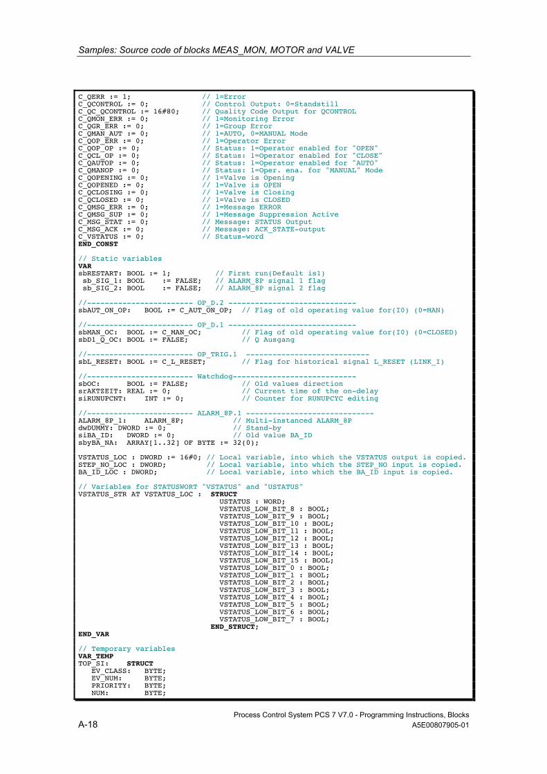
Samples: Source code of blocks MEAS_MON, MOTOR and VALVE
Process Control System PCS 7 V7.0 - Programming Instructions, Blocks A-18 A5E00807905-01
C_QERR := 1; // 1=Error C_QCONTROL := 0; // Control Output: 0=Standstill C_QC_QCONTROL := 16#80; // Quality Code Output for QCONTROL C_QMON_ERR := 0; // 1=Monitoring Error C_QGR_ERR := 0; // 1=Group Error C_QMAN_AUT := 0; // 1=AUTO, 0=MANUAL Mode C_QOP_ERR := 0; // 1=Operator Error C_QOP_OP := 0; // Status: 1=Operator enabled for "OPEN" C_QCL_OP := 0; // Status: 1=Operator enabled for "CLOSE" C_QAUTOP := 0; // Status: 1=Operator enabled for "AUTO" C_QMANOP := 0; // Status: 1=Oper. ena. for "MANUAL" Mode C_QOPENING := 0; // 1=Valve is Opening C_QOPENED := 0; // 1=Valve is OPEN C_QCLOSING := 0; // 1=Valve is Closing C_QCLOSED := 0; // 1=Valve is CLOSED C_QMSG_ERR := 0; // 1=Message ERROR C_QMSG_SUP := 0; // 1=Message Suppression Active C_MSG_STAT := 0; // Message: STATUS Output C_MSG_ACK := 0; // Message: ACK_STATE-output C_VSTATUS := 0; // Status-word END_CONST // Static variables VAR sbRESTART: BOOL := 1; // First run(Default is1) sb_SIG_1: BOOL := FALSE; // ALARM_8P signal 1 flag sb_SIG_2: BOOL := FALSE; // ALARM_8P signal 2 flag //------------------------ OP_D.2 ----------------------------- sbAUT_ON_OP: BOOL := C_AUT_ON_OP; // Flag of old operating value for(I0) (0=MAN) //------------------------ OP_D.1 ----------------------------- sbMAN_OC: BOOL := C_MAN_OC; // Flag of old operating value for(I0) (0=CLOSED) sbD1_Q_OC: BOOL := FALSE; // Q Ausgang //------------------------ OP_TRIG.1 ---------------------------- sbL_RESET: BOOL := C_L_RESET; // Flag for historical signal L_RESET (LINK_I) //------------------------ Watchdog---------------------------- sbOC: BOOL := FALSE; // Old values direction srAKTZEIT: REAL := 0; // Current time of the on-delay siRUNUPCNT: INT := 0; // Counter for RUNUPCYC editing //------------------------ ALARM_8P.1 ----------------------------- ALARM_8P_1: ALARM_8P; // Multi-instanced ALARM_8P dwDUMMY: DWORD := 0; // Stand-by siBA_ID: DWORD := 0; // Old value BA_ID sbyBA_NA: ARRAY[1..32] OF BYTE := 32(0); VSTATUS_LOC : DWORD := 16#0; // Local variable, into which the VSTATUS output is copied. STEP_NO_LOC : DWORD; // Local variable, into which the STEP_NO input is copied. BA_ID_LOC : DWORD; // Local variable, into which the BA_ID input is copied. // Variables for STATUSWORT "VSTATUS" and "USTATUS" VSTATUS_STR AT VSTATUS_LOC : STRUCT USTATUS : WORD; VSTATUS_LOW_BIT_8 : BOOL; VSTATUS_LOW_BIT_9 : BOOL; VSTATUS_LOW_BIT_10 : BOOL; VSTATUS_LOW_BIT_11 : BOOL; VSTATUS_LOW_BIT_12 : BOOL; VSTATUS_LOW_BIT_13 : BOOL; VSTATUS_LOW_BIT_14 : BOOL; VSTATUS_LOW_BIT_15 : BOOL; VSTATUS_LOW_BIT_0 : BOOL; VSTATUS_LOW_BIT_1 : BOOL; VSTATUS_LOW_BIT_2 : BOOL; VSTATUS_LOW_BIT_3 : BOOL; VSTATUS_LOW_BIT_4 : BOOL; VSTATUS_LOW_BIT_5 : BOOL; VSTATUS_LOW_BIT_6 : BOOL; VSTATUS_LOW_BIT_7 : BOOL; END_STRUCT; END_VAR // Temporary variables VAR_TEMP TOP_SI: STRUCT EV_CLASS: BYTE; EV_NUM: BYTE; PRIORITY: BYTE; NUM: BYTE;
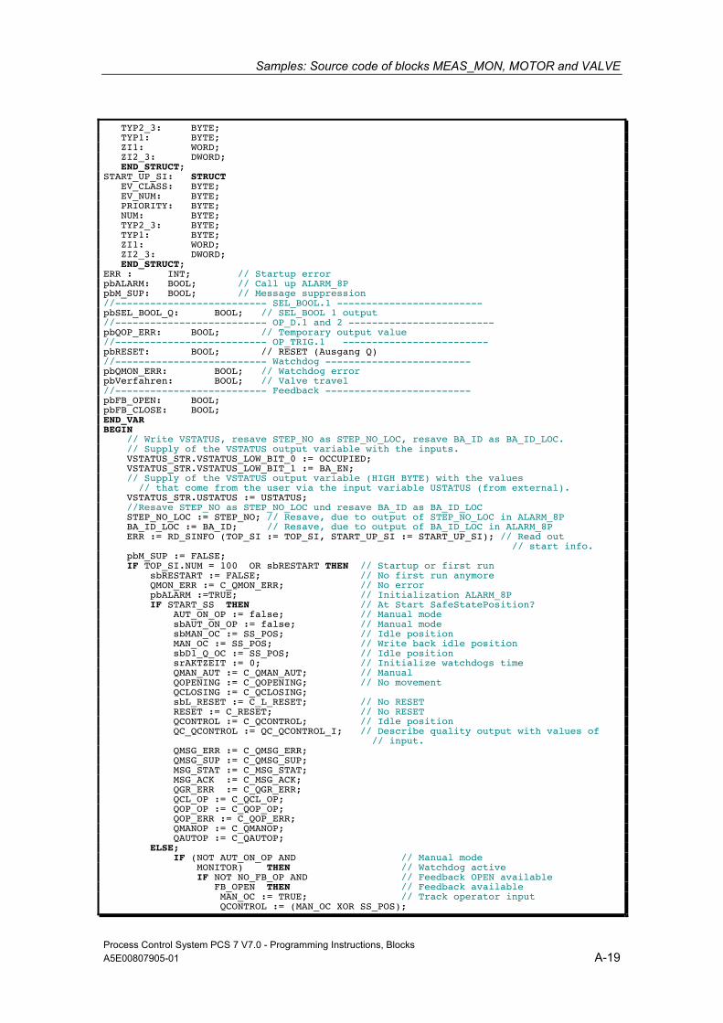
Samples: Source code of blocks MEAS_MON, MOTOR and VALVE
Process Control System PCS 7 V7.0 - Programming Instructions, Blocks A5E00807905-01 A-19
TYP2_3: BYTE; TYP1: BYTE; ZI1: WORD; ZI2_3: DWORD; END_STRUCT; START_UP_SI: STRUCT EV_CLASS: BYTE; EV_NUM: BYTE; PRIORITY: BYTE; NUM: BYTE; TYP2_3: BYTE; TYP1: BYTE; ZI1: WORD; ZI2_3: DWORD; END_STRUCT; ERR : INT; // Startup error pbALARM: BOOL; // Call up ALARM_8P pbM_SUP: BOOL; // Message suppression //-------------------------- SEL_BOOL.1 ------------------------- pbSEL_BOOL_Q: BOOL; // SEL_BOOL 1 output //-------------------------- OP_D.1 and 2 ------------------------- pbQOP_ERR: BOOL; // Temporary output value //-------------------------- OP_TRIG.1 ------------------------- pbRESET: BOOL; // RESET (Ausgang Q) //-------------------------- Watchdog ------------------------- pbQMON_ERR: BOOL; // Watchdog error pbVerfahren: BOOL; // Valve travel //-------------------------- Feedback ------------------------- pbFB_OPEN: BOOL; pbFB_CLOSE: BOOL; END_VAR BEGIN // Write VSTATUS, resave STEP_NO as STEP_NO_LOC, resave BA_ID as BA_ID_LOC. // Supply of the VSTATUS output variable with the inputs. VSTATUS_STR.VSTATUS_LOW_BIT_0 := OCCUPIED; VSTATUS_STR.VSTATUS_LOW_BIT_1 := BA_EN; // Supply of the VSTATUS output variable (HIGH BYTE) with the values // that come from the user via the input variable USTATUS (from external). VSTATUS_STR.USTATUS := USTATUS; //Resave STEP_NO as STEP_NO_LOC und resave BA_ID as BA_ID_LOC STEP_NO_LOC := STEP_NO; // Resave, due to output of STEP_NO_LOC in ALARM_8P BA_ID_LOC := BA_ID; // Resave, due to output of BA_ID_LOC in ALARM_8P ERR := RD_SINFO (TOP_SI := TOP_SI, START_UP_SI := START_UP_SI); // Read out // start info. pbM_SUP := FALSE; IF TOP_SI.NUM = 100 OR sbRESTART THEN // Startup or first run sbRESTART := FALSE; // No first run anymore QMON_ERR := C_QMON_ERR; // No error pbALARM :=TRUE; // Initialization ALARM_8P IF START_SS THEN // At Start SafeStatePosition? AUT_ON_OP := false; // Manual mode sbAUT_ON_OP := false; // Manual mode sbMAN_OC := SS_POS; // Idle position MAN_OC := SS_POS; // Write back idle position sbD1_Q_OC := SS_POS; // Idle position srAKTZEIT := 0; // Initialize watchdogs time QMAN_AUT := C_QMAN_AUT; // Manual QOPENING := C_QOPENING; // No movement QCLOSING := C_QCLOSING; sbL_RESET := C_L_RESET; // No RESET RESET := C_RESET; // No RESET QCONTROL := C_QCONTROL; // Idle position QC_QCONTROL := QC_QCONTROL_I; // Describe quality output with values of // input. QMSG_ERR := C_QMSG_ERR; QMSG_SUP := C_QMSG_SUP; MSG_STAT := C_MSG_STAT; MSG_ACK := C_MSG_ACK; QGR_ERR := C_QGR_ERR; QCL_OP := C_QCL_OP; QOP_OP := C_QOP_OP; QOP_ERR := C_QOP_ERR; QMANOP := C_QMANOP; QAUTOP := C_QAUTOP; ELSE; IF (NOT AUT_ON_OP AND // Manual mode MONITOR) THEN // Watchdog active IF NOT NO_FB_OP AND // Feedback OPEN available FB_OPEN THEN // Feedback available MAN_OC := TRUE; // Track operator input QCONTROL := (MAN_OC XOR SS_POS);
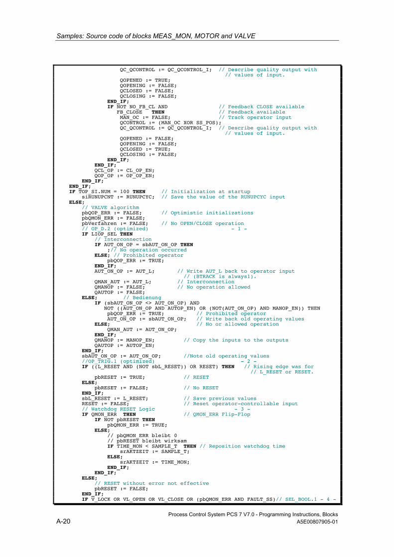
Samples: Source code of blocks MEAS_MON, MOTOR and VALVE
Process Control System PCS 7 V7.0 - Programming Instructions, Blocks A-20 A5E00807905-01
QC_QCONTROL := QC_QCONTROL_I; // Describe quality output with // values of input. QOPENED := TRUE; QOPENING := FALSE; QCLOSED := FALSE; QCLOSING := FALSE; END_IF; IF NOT NO_FB_CL AND // Feedback CLOSE available FB_CLOSE THEN // Feedback available MAN_OC := FALSE; // Track operator input QCONTROL := (MAN_OC XOR SS_POS); QC_QCONTROL := QC_QCONTROL_I; // Describe quality output with // values of input. QOPENED := FALSE; QOPENING := FALSE; QCLOSED := TRUE; QCLOSING := FALSE; END_IF; END_IF; QCL_OP := CL_OP_EN; QOP_OP := OP_OP_EN; END_IF; END_IF; IF TOP_SI.NUM = 100 THEN // Initialization at startup siRUNUPCNT := RUNUPCYC; // Save the value of the RUNUPCYC input ELSE; // VALVE algorithm pbQOP_ERR := FALSE; // Optimistic initializations pbQMON_ERR := FALSE; pbVerfahren := FALSE; // No OPEN/CLOSE operation // OP_D.2 (optimized) - 1 - IF LIOP_SEL THEN // Interconnection IF AUT_ON_OP = sbAUT_ON_OP THEN ;// No operation occurred ELSE; // Prohibited operator pbQOP_ERR := TRUE; END_IF; AUT_ON_OP := AUT_L; // Write AUT_L back to operator input // (BTRACK is always1). QMAN_AUT := AUT_L; // Interconnection QMANOP := FALSE; // No operation allowed QAUTOP := FALSE; ELSE; // Bedienung IF (sbAUT_ON_OP <> AUT_ON_OP) AND NOT ((AUT_ON_OP AND AUTOP_EN) OR (NOT(AUT_ON_OP) AND MANOP_EN)) THEN pbQOP_ERR := TRUE; // Prohibited operator AUT_ON_OP := sbAUT_ON_OP; // Write back old operating values ELSE; // No or allowed operation QMAN_AUT := AUT_ON_OP; END_IF; QMANOP := MANOP_EN; // Copy the inputs to the outputs QAUTOP := AUTOP_EN; END_IF; sbAUT_ON_OP := AUT_ON_OP; //Note old operating values //OP_TRIG.1 (optimized) - 2 - IF ((L_RESET AND (NOT sbL_RESET)) OR RESET) THEN // Rising edge was for // L_RESET or RESET. pbRESET := TRUE; // RESET ELSE; pbRESET := FALSE; // No RESET END_IF; sbL_RESET := L_RESET; // Save previous values RESET := FALSE; // Reset operator-controllable input // Watchdog RESET Logic - 3 - IF QMON_ERR THEN // QMON_ERR Flip-Flop IF NOT pbRESET THEN pbQMON_ERR := TRUE; ELSE; // pbQMON_ERR bleibt 0 // pbRESET bleibt wirksam IF TIME_MON < SAMPLE_T THEN // Reposition watchdog time srAKTZEIT := SAMPLE_T; ELSE; srAKTZEIT := TIME_MON; END_IF; END_IF; ELSE; // RESET without error not effective pbRESET := FALSE; END_IF; IF V_LOCK OR VL_OPEN OR VL_CLOSE OR (pbQMON_ERR AND FAULT_SS)// SEL_BOOL.1 - 4 -

Samples: Source code of blocks MEAS_MON, MOTOR and VALVE
Process Control System PCS 7 V7.0 - Programming Instructions, Blocks A5E00807905-01 A-21
THEN pbSEL_BOOL_Q := SS_POS; // Idle position IF (NOT V_LOCK) THEN IF VL_CLOSE THEN pbSEL_BOOL_Q := 0; // Close valve ELSE; IF VL_OPEN THEN pbSEL_BOOL_Q := 1; // Open valve END_IF; END_IF; END_IF; ELSE; pbSEL_BOOL_Q := AUTO_OC; // Automatic value END_IF; // OP_D.1 (optimized and expanded with LINK_ON calculation) - 5 - IF QMAN_AUT OR V_LOCK OR VL_OPEN OR VL_CLOSE OR (pbQMON_ERR AND FAULT_SS) // LINK_ON THEN // Interconnection IF MAN_OC = sbMAN_OC THEN ; // Keine Bedienung erfolgt ELSE; pbQOP_ERR := TRUE; // Prohibited operator END_IF; IF sbD1_Q_OC <> pbSEL_BOOL_Q THEN // Valve travel? pbVerfahren := TRUE; sbD1_Q_OC := pbSEL_BOOL_Q; // LINK_I END_IF; MAN_OC := sbD1_Q_OC; // Write output back to operator input // (BTRACK is always1). ELSE; // Bedienung IF (sbMAN_OC <> MAN_OC) AND NOT ((MAN_OC AND OP_OP_EN) OR (NOT(MAN_OC) AND CL_OP_EN)) THEN pbQOP_ERR := TRUE; // Prohibited operator MAN_OC := sbMAN_OC; // Write back old operating values ELSE; IF sbD1_Q_OC <> MAN_OC THEN // Valve travel? // Allowed operator pbVerfahren := TRUE; sbD1_Q_OC := MAN_OC; END_IF; END_IF; END_IF; sbMAN_OC := MAN_OC; //Note old operating values IF pbVerfahren // Valve is traveled -> Reposition watchdog time THEN IF TIME_MON < SAMPLE_T THEN srAKTZEIT := SAMPLE_T; ELSE; srAKTZEIT := TIME_MON; END_IF; END_IF;
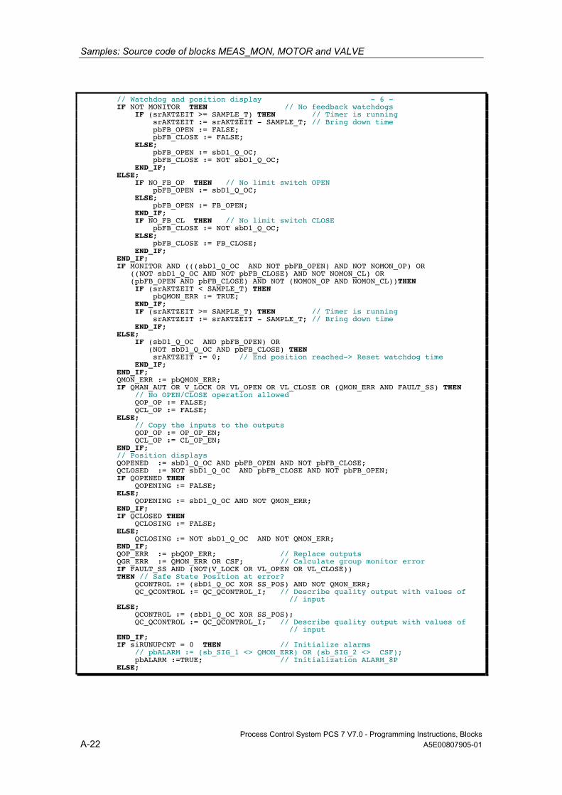
Samples: Source code of blocks MEAS_MON, MOTOR and VALVE
Process Control System PCS 7 V7.0 - Programming Instructions, Blocks A-22 A5E00807905-01
// Watchdog and position display - 6 - IF NOT MONITOR THEN // No feedback watchdogs IF (srAKTZEIT >= SAMPLE_T) THEN // Timer is running srAKTZEIT := srAKTZEIT - SAMPLE_T; // Bring down time pbFB_OPEN := FALSE; pbFB_CLOSE := FALSE; ELSE; pbFB_OPEN := sbD1_Q_OC; pbFB_CLOSE := NOT sbD1_Q_OC; END_IF; ELSE; IF NO_FB_OP THEN // No limit switch OPEN pbFB_OPEN := sbD1_Q_OC; ELSE; pbFB_OPEN := FB_OPEN; END_IF; IF NO_FB_CL THEN // No limit switch CLOSE pbFB_CLOSE := NOT sbD1_Q_OC; ELSE; pbFB_CLOSE := FB_CLOSE; END_IF; END_IF; IF MONITOR AND (((sbD1_Q_OC AND NOT pbFB_OPEN) AND NOT NOMON_OP) OR ((NOT sbD1_Q_OC AND NOT pbFB_CLOSE) AND NOT NOMON_CL) OR (pbFB_OPEN AND pbFB_CLOSE) AND NOT (NOMON_OP AND NOMON_CL))THEN IF (srAKTZEIT < SAMPLE_T) THEN pbQMON_ERR := TRUE; END_IF; IF (srAKTZEIT >= SAMPLE_T) THEN // Timer is running srAKTZEIT := srAKTZEIT - SAMPLE_T; // Bring down time END_IF; ELSE; IF (sbD1_Q_OC AND pbFB_OPEN) OR (NOT sbD1_Q_OC AND pbFB_CLOSE) THEN srAKTZEIT := 0; // End position reached-> Reset watchdog time END_IF; END_IF; QMON_ERR := pbQMON_ERR; IF QMAN_AUT OR V_LOCK OR VL_OPEN OR VL_CLOSE OR (QMON_ERR AND FAULT_SS) THEN // No OPEN/CLOSE operation allowed QOP_OP := FALSE; QCL_OP := FALSE; ELSE; // Copy the inputs to the outputs QOP_OP := OP_OP_EN; QCL_OP := CL_OP_EN; END_IF; // Position displays QOPENED := sbD1_Q_OC AND pbFB_OPEN AND NOT pbFB_CLOSE; QCLOSED := NOT sbD1_Q_OC AND pbFB_CLOSE AND NOT pbFB_OPEN; IF QOPENED THEN QOPENING := FALSE; ELSE; QOPENING := sbD1_Q_OC AND NOT QMON_ERR; END_IF; IF QCLOSED THEN QCLOSING := FALSE; ELSE; QCLOSING := NOT sbD1_Q_OC AND NOT QMON_ERR; END_IF; QOP_ERR := pbQOP_ERR; // Replace outputs QGR_ERR := QMON_ERR OR CSF; // Calculate group monitor error IF FAULT_SS AND (NOT(V_LOCK OR VL_OPEN OR VL_CLOSE)) THEN // Safe State Position at error? QCONTROL := (sbD1_Q_OC XOR SS_POS) AND NOT QMON_ERR; QC_QCONTROL := QC_QCONTROL_I; // Describe quality output with values of // input ELSE; QCONTROL := (sbD1_Q_OC XOR SS_POS); QC_QCONTROL := QC_QCONTROL_I; // Describe quality output with values of // input END_IF; IF siRUNUPCNT = 0 THEN // Initialize alarms // pbALARM := (sb_SIG_1 <> QMON_ERR) OR (sb_SIG_2 <> CSF); pbALARM :=TRUE; // Initialization ALARM_8P ELSE;
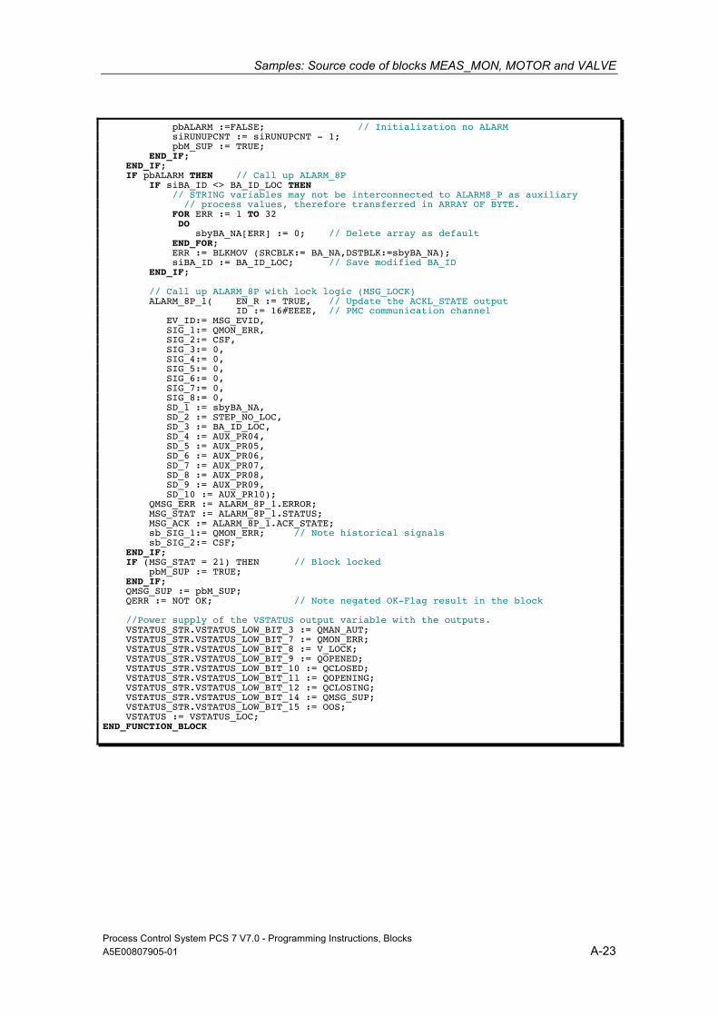
Samples: Source code of blocks MEAS_MON, MOTOR and VALVE
Process Control System PCS 7 V7.0 - Programming Instructions, Blocks A5E00807905-01 A-23
pbALARM :=FALSE; // Initialization no ALARM siRUNUPCNT := siRUNUPCNT - 1; pbM_SUP := TRUE; END_IF; END_IF; IF pbALARM THEN // Call up ALARM_8P IF siBA_ID <> BA_ID_LOC THEN // STRING variables may not be interconnected to ALARM8_P as auxiliary // process values, therefore transferred in ARRAY OF BYTE. FOR ERR := 1 TO 32 DO sbyBA_NA[ERR] := 0; // Delete array as default END_FOR; ERR := BLKMOV (SRCBLK:= BA_NA,DSTBLK:=sbyBA_NA); siBA_ID := BA_ID_LOC; // Save modified BA_ID END_IF; // Call up ALARM_8P with lock logic (MSG_LOCK) ALARM_8P_1( EN_R := TRUE, // Update the ACKL_STATE output ID := 16#EEEE, // PMC communication channel EV_ID:= MSG_EVID, SIG_1:= QMON_ERR, SIG_2:= CSF, SIG_3:= 0, SIG_4:= 0, SIG_5:= 0, SIG_6:= 0, SIG_7:= 0, SIG_8:= 0, SD_1 := sbyBA_NA, SD_2 := STEP_NO_LOC, SD_3 := BA_ID_LOC, SD_4 := AUX_PR04, SD_5 := AUX_PR05, SD_6 := AUX_PR06, SD_7 := AUX_PR07, SD_8 := AUX_PR08, SD_9 := AUX_PR09, SD_10 := AUX_PR10); QMSG_ERR := ALARM_8P_1.ERROR; MSG_STAT := ALARM_8P_1.STATUS; MSG_ACK := ALARM_8P_1.ACK_STATE; sb_SIG_1:= QMON_ERR; // Note historical signals sb_SIG_2:= CSF; END_IF; IF (MSG_STAT = 21) THEN // Block locked pbM_SUP := TRUE; END_IF; QMSG_SUP := pbM_SUP; QERR := NOT OK; // Note negated OK-Flag result in the block //Power supply of the VSTATUS output variable with the outputs. VSTATUS_STR.VSTATUS_LOW_BIT_3 := QMAN_AUT; VSTATUS_STR.VSTATUS_LOW_BIT_7 := QMON_ERR; VSTATUS_STR.VSTATUS_LOW_BIT_8 := V_LOCK; VSTATUS_STR.VSTATUS_LOW_BIT_9 := QOPENED; VSTATUS_STR.VSTATUS_LOW_BIT_10 := QCLOSED; VSTATUS_STR.VSTATUS_LOW_BIT_11 := QOPENING; VSTATUS_STR.VSTATUS_LOW_BIT_12 := QCLOSING; VSTATUS_STR.VSTATUS_LOW_BIT_14 := QMSG_SUP; VSTATUS_STR.VSTATUS_LOW_BIT_15 := OOS; VSTATUS := VSTATUS_LOC; END_FUNCTION_BLOCK

Samples: Source code of blocks MEAS_MON, MOTOR and VALVE
Process Control System PCS 7 V7.0 - Programming Instructions, Blocks A-24 A5E00807905-01

Process Control System PCS 7 V7.0 - Programming Instructions for Blocks A5E00807905-01 Glossary-1
Glossary
A
Asynchronous OBs Asynchronous OBs (organization blocks) are called by the operating system of the CPU when asynchronous events occur (for example errors).
AUTHOR Block attribute:
When a block library is used, this contains the library name. It is also used to identify the help file belonging to the library.
B
BATCH flexible A program package for creating complex recipe controls for the entire range from small to large-scale applications.
Block attribute Using the block attributes ( FUNCTION_BLOCK, TITLE, List of system attributes, AUTHOR, NAME, VERSION, FAMILY, KNOW_HOW_PROTECT) of the block, you can influence the object properties of your block.
Block header 1. Section of the PLC block with administrative information ( block
attributes).
2. The upper part of the block in the graphic representation in CFC containing the name (block type, block name), comment and the task assignment (run-time property).
Block icon Symbolic display of the most important information of a PLC block. The corresponding faceplate can be opened with the block icon.
Glossary
Process Control System PCS 7 V7.0 - Programming Instructions for Blocks Glossary-2 A5E00807905-01
C
CFC Continuous Function Chart
1. This is a function chart on which blocks can be placed, interconnected, and assigned parameters. A CFC chart consists of 1 to 26 chart partitions each with 6 sheets.
2. Editor for plant-oriented graphic configuration of automation tasks. Using the CFC editor, a complete software structure (CFC chart) can be created from ready-made blocks.
CNT file Optional part of an online help system. The CNT file contains the contents of the online help system.
Code section Part of a block containing the algorithm of the block.
D
Declaration section Part of a block defining the interface of the block and the data it uses internally.
F
Faceplate Graphic representation of all the elements of a PLC block intended for operator control and monitoring on an OS.
FAMILY Block attribute:
When a block library is used, this contains a common name for a subset of the blocks. FAMILY and NAME form part of the key for locating the help text of a block in the online help system.
Function (FC) Specified in IEC 1131–3 as a software unit that provides a single result when it executes (can also be a structured data type) and does not have memory for storing data. The major difference between an FC and an FB is the absence of data storage.
Glossary
Process Control System PCS 7 V7.0 - Programming Instructions for Blocks A5E00807905-01 Glossary-3
FUNCTION_BLOCK Block attribute:
Contains the symbolic name of the block. This is used to display the name of the block in the SIMATIC Manager and in the CFC chart.
Function block (FB) According to IEC 1131-3, a function block is a logic block with static data. Using FBs, parameters can be passing in the user program. This makes function blocks suitable for programming frequently repeated complex functions, such as controllers, mode selection. Since the FB has a memory (instance data block), its parameters, for example outputs, can be accessed at any point in the user program.
G
Global script Within WinCC, global script is the generic term for C functions created by the user that can be used throughout a project and in multiple projects.
Graphics Designer Graphic editor in WinCC for creating faceplates.
H
HID Higher-level identifier: This is made up of the name of the plant hierarchy folders that are selected to form part of the name and of the CFC chart and the block in the CFC chart.
I
Initial start The first time that a block is executed following its instantiation. Following this first execution, the parameters and modes of the block are in a defined state.

Glossary
Process Control System PCS 7 V7.0 - Programming Instructions for Blocks Glossary-4 A5E00807905-01
K
KNOW_HOW_PROTECT Block attribute:
When this attribute is set, it protects the algorithm of the block from being viewed or modified unless the source file is in the same program.
L
Library Software package with PLC blocks and/or faceplates grouped according to common features.
M
Message list From within the run-time system of WinCC, it is possible to display and edit lists of messages. The messages displayed in the lists relate only the currently active project.
Monitoring Part of the functions of an OS allowing visualization of the process parameters and statuses in various forms (numeric, graphic).
Multiple instance block A block made up of several blocks. Its instance (data storage) contains the instances (data storage) of the FBs that are called in it.
N
NAME Block attribute:
Contains the symbolic name of the block; identical to FUNCTION_BLOCK. NAME and FAMILY form part of the key for locating the help text of a block in the online help system.
Glossary
Process Control System PCS 7 V7.0 - Programming Instructions for Blocks A5E00807905-01 Glossary-5
O
OK flag The OK flag is a system-internal variable. If an error occurs during execution of an option, for example overflow with arithmetic operations, the OK flag is changed by the system and passed to the ENO block output.
Operator authorization The right assigned to the operator to modify the PLC block parameter.
Operator control Procedure in which the operator changes the value or status of a block. Generally, such operations involve input at the operator station which is then checked and passed to the block on the PLC. Here, the instruction is checked again before is assigned to the block since it is possible that process conditions have changed since the instruction was sent from the OS and received at the PLC.
P
PLC block An object belonging to a library or a block structure that contains part of the S7 user program. The blocks that are executed in the CPU of a PLC are known as PLC blocks.
Prototype picture Prototype pictures are used by WinCC to reuse picture components that have already been configured. The prototype picture technique makes use of template pictures that can be included more than once in one or more parent pictures. A prototype is simply a template that only "comes to life" in a real object. An object based on a template is created by instantiation. Several instances (on other words real objects) can be created from a template.
R
Registration file And ASCII file (.reg) containing all the information such as path, MAP IDs for online help systems, for example to enter a block in the WINDOWS NT registry. Using this registration file, the online help for a selected block can be started in the required language in CFC or in the SIMATIC Manager.
Glossary
Process Control System PCS 7 V7.0 - Programming Instructions for Blocks Glossary-6 A5E00807905-01
S
SCL Higher-level programming language for formulating solutions to technological tasks in SIMATIC S7 (similar to PASCAL) complying with the ST (structured text) language specified in IEC 1131–3.
Split Screen Wizard Component of WinCC: This initializes the monitor and display settings on the OS.
Standard view View of a faceplate in which the most important values of the corresponding PLC block are visualized.
Start info The start information is part of an organization block (OB). It informs the S7 user in detail of the event that triggered the OB call.
STL Statement List: Statement List is a textual programming language complying with IEC 1131-3 and resembling machine code.
System attributes for blocks Special attributes that prepare the PLC block for the connection to the OS or influence the installation of a block in a CFC chart.
System attributes for parameters Special attributes that influence the display of the parameter in the faceplate or its handling in the CFC chart.

Glossary
Process Control System PCS 7 V7.0 - Programming Instructions for Blocks A5E00807905-01 Glossary-7
T
TITLE Block attribute:
This information is not evaluated in PCS 7, however, it is displayed in the SIMATIC Manager in the object properties of the block in the comment field.
Trend view View of a faceplate in which the most important values of the corresponding PLC block are visualized over time.
U
UDT User-defined data types
User-defined data types (UDT) User-defined data types are special data structures that can be used in the entire CPU program after they have been defined. They cam be used like elementary or complex data types in the variable declaration of logic blocks (FCs, FBs, OBs) or as templates for creating data blocks with the same data structure.
V
VERSION Block attribute:
Contains the version number of the block View
View of a block in which certain values of a PLC block are displayed (for example, trend view, alarm view, standard view etc.).
W
WinCC Windows Control Center: A software package for plant-oriented graphic development of faceplates and for operator control and monitoring of the PLC.

Glossary
Process Control System PCS 7 V7.0 - Programming Instructions for Blocks Glossary-8 A5E00807905-01
Process Control System PCS 7 V7.0 - Programming Instructions for Blocks A5E00807905-01 Index-1
Index
" "Limit value display" bar graph ............. 2-54
A Acknowledgment of messages............. 2-57 Advanced Process Control..................... 2-1 ALARM_8 ............................................. 1-39 ALARM_8P........................................... 1-42 Analog value display ............................ 2-49 Area assignment .................................. 1-40 AS block
Structure ............................................. 1-3 User interface ..................................... 1-6
Associated vales for messages............ 1-43 Associated values ................................ 1-42 Asynchronous event............................. 1-28
B Bar graph for analog values ........ 2-50, 2-51 Basic data
Picture templates .............................. 2-83 Basic elements ..................................... 2-45 Basic Process Control ............................ 2-1 Batch ID................................................ 1-40 Batch Occupied .................................... 2-57 Batch-Sicht ........................................... 2-87 Binary value control
using a 3ComboBox ......................... 2-64 using a combo box............................ 2-62 using CheckBox_L............................ 2-61 with button......................................... 2-67 with button and color change............ 2-66
Binary value input using CheckBox_R ........................... 2-59
Bitmaps................................................. 2-80 Block diagram CONTROL...................... 1-3 Block header........................................... 1-8 Block icon
CTRL_PID....................................... 2-101 RATIO_P......................................... 2-107 SWIT_CNT...................................... 2-107
Block icon CTRL_S .......................................... 2-102 DIG_MON ....................................... 2-114 DOSE.............................................. 2-104 ELAP_CNT ..................................... 2-106
FMCS_PID ......................................2-105 FMT_PID .........................................2-105 INTERLOK ......................................2-112 MEAS_MON....................................2-106 MOT_REV.......................................2-112 MOT_SPED.....................................2-111 MOTOR ...........................................2-110 OP_A...............................................2-108 OP_D...............................................2-113 OP_D3.............................................2-113 OP_TRIG.........................................2-113 VAL_MOT........................................2-109 VALVE.............................................2-109
Block icon templates...............................2-5 Block icons............................................2-97 Block parameters ..................................1-14 Blocks
System attributes...............................1-12
C CFC block types....................................1-44 Changing languages.............................2-27 Chart connections .................................1-44 CNT file ...................................................3-2 Code section .........................................1-24 Comments.............................................1-15 Configuring messages ..........................1-39 CONTROL2 ..........................................1-44 CTRL_PID
Block icon ........................................2-101 Limits view.........................................2-95 Maintenance view..............................2-91 Parameter view .................................2-93 Standard view....................................2-89
CTRL_S Block icon ........................................2-102
D DIG_MON
Block icon ........................................2-114 DOSE
Block icon ........................................2-104 Dynamic update ....................................2-43
Index
Process Control System PCS 7 V7.0 - Programming Instructions for Blocks Index-2 A5E00807905-01
E ELAP_CNT
Block icon........................................ 2-106
F Faceplate
Configuring.......................................... 2-3 Design................................................. 2-2 Test ..................................................... 2-4
Faceplate Designer ................................ 2-5 Faceplates ............................................ 2-83 FMCS_PID
Block icon........................................ 2-105 FMT_PID
Block icon........................................ 2-105
G Global scripts.......................................... 2-6 Global views ......................................... 2-87 Group display ....................................... 2-58
H Help file................................................... 3-1 Help topic................................................ 3-1 HLP file ................................................... 3-2 Horizontal bar graph............................. 2-53
I In/out parameters ................................. 1-14 INCLUDE statement............................... 3-2 Initialization........................................... 1-25 Input parameters .................................. 1-14 Installation script..................................... 4-2 InstallShield ............................................ 4-1 INTERLOK
Block icon........................................ 2-112
L Labeling
check box.......................................... 2-60 Language ID........................................... 3-2 Library..................................................... 4-1 Local variables...................................... 1-22 Locked .................................................. 2-58
M MEAS_MON...........................................A-1
Block icon........................................ 2-106 Message class...................................... 1-41 Message origin ..................................... 1-40 Message suppression .......................... 2-56 Message view....................................... 2-87
Messages..............................................1-31 MOT_REV
Block icon ........................................2-112 MOT_SPED
Block icon ........................................2-111 MOTOR ...............................................A-7 Block icon ........................................2-110
Multiple instance ..........................1-22, 2-11 Multiple instance block..........................1-22
N Naming conventions .............................1-46
O Object properties of the block ........1-9, 1-10 Object toolkit ...........................................2-6 Online Help .............................................3-1 OP_A ....................................................1-30
Block icon ........................................2-108 OP_A_LIM ............................................1-30 OP_A_RJC ...........................................1-30 OP_D
Block icon ........................................2-113 OP_D3
Block icon ........................................2-113 OP_TRIG
Block icon ........................................2-113 Operator control functions ....................1-30 Output parameters................................1-14 Overview ...............................................2-10
P Parameter attributes .............................2-28 Parameter types....................................1-14 Permission ............................................2-71 Picture...................................................2-82 Picture templates ....................................2-6
Q Quality Code display.............................2-77
R Range of numbers ................................1-46 RATIO_P
Block icon ........................................2-107 Regional language..................................1-6 Registry file .............................................3-3

Index
Process Control System PCS 7 V7.0 - Programming Instructions for Blocks A5E00807905-01 Index-3
S S7 Library ............................................... 4-1 SAMPLE_T........................................... 1-26 SCL Compiler
settings................................................ 1-4 Scripts................................................... 2-78 Setup ...................................................... 4-2 SIMATIC BATCH.................................. 1-43 Source code ......................................... 1-47 Static text.............................................. 2-49 Static variables ..................................... 1-22 Status display
Motor................................................. 2-71 Valve ................................................. 2-70
Status display with n alternatives ......... 2-69 Status display with two alternatives...... 2-68 SUPPTIME ........................................... 1-27 SWIT_CNT
Block icon........................................ 2-107 Symbol table........................................... 1-6 System attributes
blocks................................................ 1-12 Parameters ....................................... 1-15
T Tag Logging.......................................... 2-17
Templates ...............................................2-5 Temporary variables .............................1-23 Test
Faceplate.............................................2-4 Time dependency .................................1-26 Topic .......................................................3-1
U User rights
area-specific ........................................2-8 instance-specific..................................2-8
V VAL_MOT
Block icon ........................................2-109 Valve .....................................................A-15 VALVE
Block icon ........................................2-109
W Watchdog interrupt OB .........................1-28 WinCC Graphics Designer......................2-3
Z Zahlenformatierung...............................2-15

Index
Process Control System PCS 7 V7.0 - Programming Instructions for Blocks Index-4 A5E00807905-01