process design and operating philosophies on fired process...
TRANSCRIPT
Sr.Number:OISD/DOC/2013/001
Page No. I
OISD Std-111
Second edition
FOR RESTRICTED
CIRCULATION
Draft-1
PROCESS DESIGN AND OPERATING PHILOSOPHIES
ON
FIRED PROCESS FURNACE
OISD-STANDARD-111
First Edition, March 1989
Amended edition, August, 1999 Second Edition……2015
Oil Industry Safety Directorate
Government of India
Ministry of Petroleum & Natural Gas
8th
Floor, OIDB Bhavan, Plot No. 2, Sector – 73, Noida – 201301 (U.P.)
Website: www.oisd.gov.in
Tele: 0120-2593800, Fax: 0120-2593802
Sr.Number:OISD/DOC/2013/001
Page No. II
OISD-STANDARD-111
First Edition: November 1988
Amended edition, August, 1999
FOR
RESTRICTED
CIRCULATION
PROCESS DESIGN AND OPERATING PHILOSOPHIES ON
FIRED PROCESS FURNACE
Prepared By:
COMMITTEE ON
PROCESS DESIGN AND OPERATING PHILOSOPHIES
OIL INDUSTRY SAFETY DIRECTORATE
(Ministry of Petroleum & Natural Gas)
8th
floor, Tower-A, Plot No. 2, Sector-73
NOIDA (UP)-201301

Sr.Number:OISD/DOC/2013/001
Page No. III
Preamble
Indian petroleum industry is the energy lifeline of the nation and its continuous performance is essential for sovereignty and
prosperity of the country. As the industry essentially deals with inherently inflammable substances throughout its value chai n –
upstream, midstream and downstream – Safety is of paramount importance to this industry as only safe performance at all
times can ensure optimum ROI of these national assets and resources including sustainability.
While statutory organizations were in place all along to oversee safety aspects of Indian petroleum industry, Oil Industry Sa fety
Directorate (OISD) was set up in 1986 Ministry of Petroleum and Natural Gas, Government of India as a knowledge centre for
formulation of constantly updated world-scale standards for design, layout and operation of various equipment, facility and
activities involved in this industry. Moreover, OISD was also given responsibility of monitoring implementation status of these
standards through safety audits.
In more than 25 years of its existence, OISD has developed a rigorous, multi-layer, iterative and participative process of
development of standards – starting with research by in-house experts and iterating through seeking & validating inputs from all
stake-holders – operators, designers, national level knowledge authorities and public at large – with a feedback loop of
constant updation based on ground level experience obtained through audits, incident analysis and environment scanning.
The participative process followed in standard formulation has resulted in excellent level of compliance by the industry
culminating in a safer environment in the industry. OISD – except in the Upstream Petroleum Sector – is still a regulatory (and
not a statutory) body but that has not affected implementation of the OISD standards. It also goes to prove the old adage tha t
self-regulation is the best regulation. The quality and relevance of OISD standards had been further endorsed by their adoption
in various statutory rules of the land.
Petroleum industry in India is significantly globalized at present in terms of technology content requiring its operation to keep
pace with the relevant world scale standards & practices. This matches the OISD philosophy of continuous improvement
keeping pace with the global developments in its target environment. To this end, OISD keeps track of changes through
participation as member in large number of International and national level Knowledge Organizations – both in the field of
standard development and implementation & monitoring in addition to updation of internal knowledge base through continuous
research and application surveillance, thereby ensuring that this OISD Standard, along with all other extant ones, remains
relevant, updated and effective on a real time basis in the applicable areas.
Together we strive to achieve NIL incidents in the entire Hydrocarbon Value Chai n. This, besides other issues, calls for total
engagement from all levels of the stake holder organizations, which we, at OISD, fervently look forward to.
Jai Hind!!!
Executive Director
Oil Industry Safety Directorate

Sr.Number:OISD/DOC/2013/001
Page No. IV
FOREWORD
The Oil Industry in India is nearly 100 years old. Because of various collaboration agreements, a variety of international codes, standards and practices have been in vogue. Standardization in design philosophies and operating and maintenance practices at a national level was hardly in existence. This coupled with feedback from some serious accidents that occurred in the recent past in India and abroad, emphasized the need for the industry to review the existing state of art in designing, operating and maintaining oil and gas installations.
With this in view, the Ministry of Petroleum and Natural Gas, in 1986, constituted a Safety Council assisted by Oil Industry Safety Directorate (OISD), staffed from within the industry, in formulating and implementing a series of self-regulatory measures aimed at removing obsolescence, standardizing and upgrading the existing standards to ensure safer operations. Accordingly, OISD constituted a number of Functional Committees of experts nominated from the industry to draw up standards and guidelines on various subjects.
The present document on ―Fired Process Furnaces‖ was prepared by the functional committee on ―Process Design and Operating Philosophies‖. This document is based on the accumulated knowledge and experience of Industry members and the various national and international codes and practices. It is hoped that provisions of this document, if implemented objectively, may go a long way to improve the safety and reduce accidents in Oil and Gas Industry. Suggestions are invited from the users after it is put into practice to improve the document further. Suggestions for amendments to this document should be addressed to :
The Co-ordinator,
Committee on ―Process Design and Operating Philosophies‖,
OIL INDUSTRY SAFETY DIRECTORATE
(Ministry of Petroleum & Natural Gas)
8th
floor, Tower-A, Plot No. 2, Sector-73 NOIDA (UP)-201301
Sr.Number:OISD/DOC/2013/001
Page No. V
NOTE
OIL publications are prepared for use in the Oil and gas industry under Ministry of Petroleum and Natural Gas. These are the property of Ministry of Petroleum and Natural Gas and shall not be reproduced or copied and loaned or exhibited to others without written consent from OISD.
Though every effort has been made to assure the accuracy and reliability of data contained in these documents, OISD hereby expressly disclaims any liability or responsibility for loss or damage resulting from their use.
These documents are intended only to supplement and not replace the prevailing statutory requirements.

Page No. VI
FUNCTIONAL COMMITTEE
(SECOND EDITION)
ON
PROCESS DESIGN AND OPERATING
PHILOSOPHIES ON
FIRED PROCESS FURNACE LIST OF MEMBERS
Name Designation/ Organisation Status
S/Shri
1. Suresh C.Gupta DGM (HMTD) Engineers India Ltd. Team Leader
2. M.K.Sinha Associate V.P.-Technip KTI Member
3. Jayesh Gajjar GM-Operation- Essar Oil Member
4. Rakesh Mittal DGM –GAIL India Ltd Member
5. Mandar R.Joshi Sr. GM- Reliance Industries Member
6. M.S.Krishnamoorthy Chief Mgr.(Process)-BPCL-MR Member
7. Mukesh Mohan Chief Manager-RHQ—IOCL Member
8. Ugrasen Yadav Jt.-GM-Process—Technip KTI Member
9. Y.K.Lodha V.P.Technical—Reliance Industries Member
10. M.S. Sudarshan DGM (TS: Env.)MRPL Member
11. Sobhan Konwar NRL Member
12. Mr. Santosh P.Nigam Process Mgr. IOCL-Panipat Member
13. M.Gupta Addl. Director-OISD Member
14. P.S.Rao Addl. Director (Process)--OISD Member
15. A.K.Arora Addl. Director(Engg.)-OISD Member Co-ordinator
In addition to the above, several experts from the industry contributed in the preparation, review and
finalization of the document.
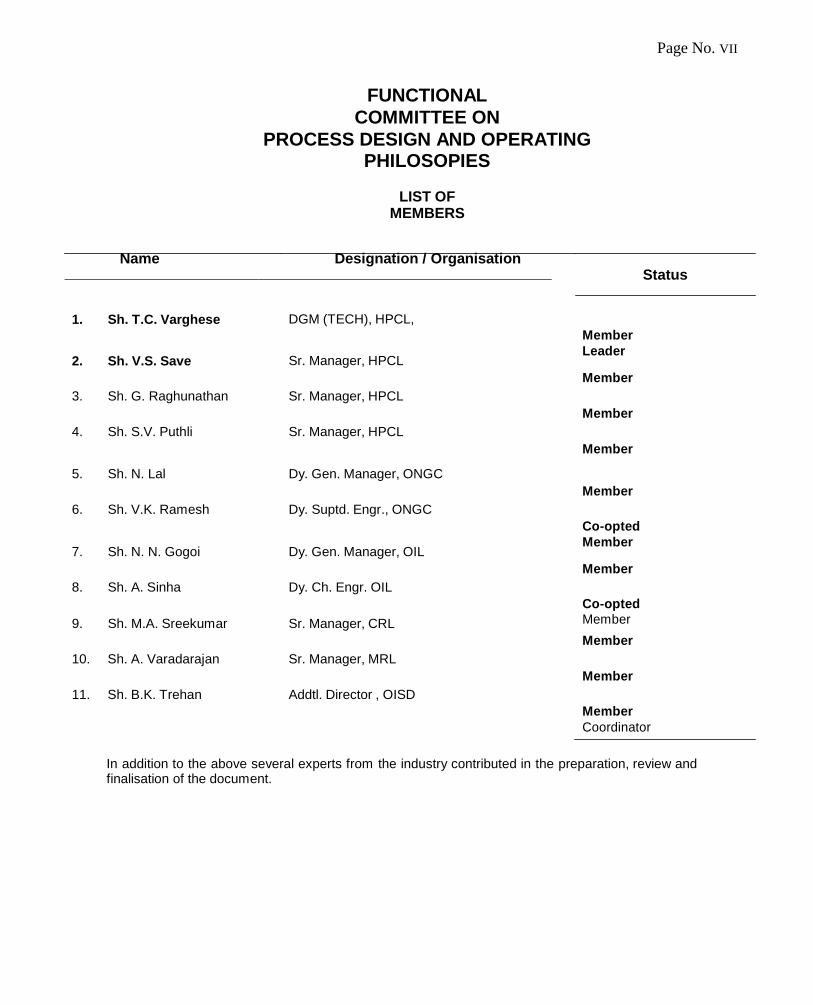
Page No. VII
Name Designation / Organisation
1. Sh. T.C. Varghese
DGM (TECH), HPCL,
2. Sh. V.S. Save Sr. Manager, HPCL
3. Sh. G. Raghunathan
Sr. Manager, HPCL
4. Sh. S.V. Puthli
Sr. Manager, HPCL
5. Sh. N. Lal
Dy. Gen. Manager, ONGC
6. Sh. V.K. Ramesh
Dy. Suptd. Engr., ONGC
7. Sh. N. N. Gogoi Dy. Gen. Manager, OIL
8. Sh. A. Sinha
Dy. Ch. Engr. OIL
9. Sh. M.A. Sreekumar Sr. Manager, CRL
10. Sh. A. Varadarajan
Sr. Manager, MRL
11. Sh. B.K. Trehan
Addtl. Director , OISD
FUNCTIONAL
COMMITTEE ON
PROCESS DESIGN AND OPERATING PHILOSOPIES
LIST OF
MEMBERS
Status
Member
Leader
Member
Member
Member
Member
Co-opted
Member
Member
Co-opted Member
Member
Member
Member
Coordinator
In addition to the above several experts from the industry contributed in the preparation, review and finalisation of the document.

Page No. VIII
PROCESS DESIGN AND OPERATING PHILOSOPHIES ON PROCESS FURNACES
CONTENTS
SL. NO.
DETAILS PAGE NO
1.0 INTRODUCTION 1
2.0 SCOPE
1
3.0 DEFINITIONS 1
4.0
LOCATION 2
4.1 General 2 4.2 Safe Distance from Roads 3 4.3 Wind Direction 3 4.4 F.D. Fan Location 3
5.0 CLEARANCES/ACCESSABILITY 3 5.1 Bottom Fired Furnaces 3
5.2 Multifloor Side Fired Furnaces 3
5.3 Valves 3
5.4 Stack Dampers 3
5.5 Explosion Doors 3
6.0
BASIC DESIGN CRITERIA
4 6.1 Configuration 4
6.2 Materials of Construction 4
6.3 Heat Flux 4
6.4 Corrosion Allowance 4
6.5 Ladders/Platforms 4
6.6 Personnel Protection 4
6.7 Peep Holes 4
7.0
PROCESS SYSTEM
4 7.1 Pass Flow Control & Monitoring 4
7.2 Pressure Monitoring 5
7.3 Temperature Monitoring 5
8.0
FIRING SYSTEM
5 8.1 Burner Mounting 5 8.2 Pilot Burners 5
8.3 Burner Lighting 5
8.4 Fuel Gas Control Valve 5
8.5 Blinding of Fuel Gas/Oil 5
8.6 Knock Out Pots 5
9.0 UTILITY SYSTEM 6
9.1 Coil Purge 6
9.2 Box Purge Steam 6
10.0 Safety Instrumentation
6
10.1 Indications/Trend/ Recording 6

Page No. IX
10.2 Alarms 7
10.3 Shutdown System 7
10.4 Typical Furnace Instrumentation 8
11.0
SAFETY IN FURNACE OPERATION 8
11.1 Personal Protection 8
11.2 Display Board 8
11.3 Furnace Lighting 8
11.4 Furnace Emergency Shutdown 8
11.5 Tube Failure 9
12.0 GUIDELINES FOR SPECIALITY FURNACES 9
12.1 Pressure & Temperature Monitoring 9
12.2
Safety Instrumentation 9
12.3 Firebox Purging 11
12.4 Decoking 11
13.0 OPERATING CHECKS 11
13.1 Pressure Survey 11
13.2 Safety Audit 12
14.0 DECOKING SYSTEMS 12
14.1 Flow measurement 12
14.2 Temperature Measurement 12
14.3 Monitoring of Decoking 12
14.4 Effluent Disposal Systems 13
14.5 Tests after Decoking 13
14.6 Decoking Schematic 13
15.0
GENERAL 13
15.1 House-Keeping 13
15.2 Safety Shower 13
15.3 Fire Fighting Facilities 13
16.0
REFERENCES 13
ANNEXURES
I Typical Arrangement for coil purge steam/inert gas to a four pass furnace
14
II Safety Instrumentation for a four pass furnace 15
III Decoking system for a four pass furnace 16
IV TYPICAL DIAGRAM OF STEAM REFORMERMING FURNACES 17
V TYPICAL DIAGRAM OF CRACKING FURNACES 18

“OISD hereby expressly disclaims any liability or responsibility for loss or damage resulting
from the use of OISD Standards/Guidelines.”
OISD – STD – 111 Page No. 1
PROCESS DESIGN AND OPERATING PHILOSOPHIES ON FIRED
PROCESS FURNACE
PROCESS DESIGN AND OPERATING PHILOSOPHIES
ON FIRED PROCESS FURNACE
1.0 INTRODUCTION
Fired Process Furnaces are critical components of process plants. These are primarily used to heat hydrocarbons of all types, from heavy crude oils and asphalt to the lightest hydrocarbon liquids or gases. These may also be used to heat other substances such as air or steam, or used for incineration.
Safety and operational efficiency should be the primary factors in design consideration and operation for furnace.
2.0 SCOPE
This document covers safety provisions in fired process furnaces in Petroleum Refineries, Gas Processing Plants & Petrochemicals, which include
(a) General Process Furnaces & (b) Special Furnaces like steam/ methane reformer furnace and pyrolysis/cracker furnace.
However additional safety features have to be provided depending on individual situations. This document does not include items like direct fired heaters of FCCU, SRU, incinerators and heater treaters for E&P installations . For specialty furnaces like Steam Methane Reformers (SMR) and Pyrolysis/Cracking Furnaces, safety guidelines are included in Section 12.0. All other sections of this Standard are not applicable for speciality furnaces unless otherwise specified in section 12. In this document, "Shall" to be understood as mandatory; and "Should" to be understood as recommended practice.
3.0 DEFINITIONS
3.1 Air Pre Heater: Heat transfer apparatus through which combustion air is passed & heated by a medium of higher temperature such as combustion products, steam or other fluid.
3.2 Balance Draft Heater: Heater that uses forced draft fans to supply combustion air and uses induced
draft fans to remove flue gases.
3.3 Breeching: Heater section where flue gases are collected after the last convection coil for transmission to the stack or the outlet ductwork.
3.4 Burner: Device that introduces fuel and air into a heater at the desired velocities, turbulence and
concentration to establish and maintain proper ignition and combustion. 3.5 Convection Section: Portion of the heater in which the heat is transferred to the tubes primarily by
convection.
3.6 Crossover: Interconnecting piping between any two heater-coil sections.
3.7 Damper: Device for introducing a variable resistance in order to regulate the flow of flue gas or air. 3.8 Flue Gas: Gaseous product of combustion including excess air.

“OISD hereby expressly disclaims any liability or responsibility for loss or damage resulting
from the use of OISD Standards/Guidelines.”
OISD – STD – 111 Page No. 2
PROCESS DESIGN AND OPERATING PHILOSOPHIES ON FIRED
PROCESS FURNACE
3.9 Forced – draft Heater: Heater for which combustion air is supplied by a fan or other mechanical
means. 3.10 General process furnaces: General process furnaces are either box type or cylindrical case type.
Heating coils in horizontal or vertical or helical orientation are located inside the casing. Heater has convection section and radiation section. Burners are installed at the bottom in case of cylindrical furnace. In case of box type furnace burners are located either at bottom or at sidewalls.
3.11. Header Return Bend: Cast or wrought iron fitting shaped in a 180
0 bend, used to connect two or
more tubes.
3.12 Induced – draft heater: Heater that uses a fan to remove flue gases and to maintain a negative pressure in the heater to induce combustion air without a force draft fan.
3.13 Natural – draft Heater: Heater in which a stack induces the combustion air and removes the flue
gases.
3.14 Pilot: Small burner that provides ignition energy to light the main burner.
3.15 Plenum Windbox: Chamber surrounding the burners that is used to distribute air to the burners or reduce combustion noise.
3.16 Radiant Section: Portion of the heater in which heat is transferred to the tubes primarily by radiation. 3.17 Special Furnaces
a) Steam/ Methane Reformer furnace : Steam Reformer is a Reaction Furnace with a Radiant
section containing vertical tubes filled with reforming catalyst. Depending upon the location of the burners, Reformer can be classified as Top fired, Bottom fired or Side fired reformer. In these furnaces, steam reacts with the Hydrocarbon feed such as natural gas or naphtha at high temperature for producing Hydrogen, CO or other useful products.(Refer Annexure-IV for Typical sketch of Steam Methane Reformer).
b) Pyrolysis/ cracking furnace: They are similar to steam/methane reforming furnace. These are
fired heaters used for pyrolytic cracking of hydrocarbons along with steam in order to produce olefins. In Cracker furnaces, large hydrocarbon molecules are broken down into smaller and more useful ones in presence of catalyst or with steam. .(Refer Annexure-V for Typical sketch of Pyrolysis/ cracking furnace). The reaction in the tubes is usually carburizing and requires that the surfaces be smooth from boring or honing and that the material be more resistant to carburizing.
3.18 Stack: Vertical conduit used to discharge flue gas to the atmosphere.
4.0 LOCATION
The following factors should be considered while locating a fired process furnace:
4.1 GENERAL
Furnace should be located only at edges of the process units to limit the hazard of open flame to a small part of the plant facing the furnace and also to facilitate easy fire fighting operations in case fire breaks out in the furnace. Also the furnace shall be at least 15 meters away from the nearest process equipment handling hydrocarbon, without any oily sewer pits, open sampling points etc. in between, from where hydrocarbon could emit vapours when the furnace is on.
“OISD hereby expressly disclaims any liability or responsibility for loss or damage resulting
from the use of OISD Standards/Guidelines.”
OISD – STD – 111 Page No. 3
PROCESS DESIGN AND OPERATING PHILOSOPHIES ON FIRED
PROCESS FURNACE
Any chances of accumulation of HC vapour /liquid within 15 m radius should be avoided. Neutralization pit of APH wash effluent may be located within this area with suitable curb wall and proper cover to avoid HC ingress.
4.2 SAFE DISTANCE FROM ROADS
There shall be a minimum distance of 15 meters form the periphery of the furnace to the edge of any road with vehicular traffic.
4.3 WIND DIRECTION
Furnaces should be located upwind or side wind from the Prevailing wind direction, from the rest of the plant.
4.4 F.D. FAN LOCATION
F.D fans wherever applicable should be located at grade. Air intake to the FD fan, should be at the periphery of heater battery limit (away from pipe rack) so as to minimize possibility of hydrocarbon suction into them.
5.0 CLEARANCE/ACCESSIBILITY
5.1 BOTTOM FIRED FURNACES
There should be a minimum of 1.75 meters of headroom for the bottom fired furnace floor including plenum chamber, if any, above grade for operational conveniences and safety.
5.2 MULTIFLOOR SIDE FIRED FURNACES
For multi floor side fired furnaces, 1.0 meter wide platform and 2.0 meters high headroom should be provided.
5.3 VALVES
Unless remote operated, the valves on the fire box purging and coil purging steam lines shall be located at least 15 meters away from the furnace in the form of a manifold and distinctly marked for easy identification. The box purging line manual isolation valve mounting shall be stem facing downward or horizontal position. For the bottom fired furnaces, individual burner’s fuel supply valves should be located on the first platform near the peephole/sight glass, for safe operation.
5.4 STACK DAMPERS
Stack dampers should be operable from ground. For natural/ forced draft furnaces, the stack damper shall be provided with ―minimum stop‖ feature to prevent full closure. Position of damper while in operation shall be distinctly visible from ground.
5.5 EXPLOSION DOORS
Explosion doors shall be provided for all furnaces to release accidental over pressures. Explosion doors should be located in such a way that the discharge is directed to a safe area.
“OISD hereby expressly disclaims any liability or responsibility for loss or damage resulting
from the use of OISD Standards/Guidelines.”
OISD – STD – 111 Page No. 4
PROCESS DESIGN AND OPERATING PHILOSOPHIES ON FIRED
PROCESS FURNACE
6.0 BASIC DESIGN CRITERIA
6.1 CONFIGURATION
The selection of the configuration of furnace, viz. vertical, horizontal, bottom fired, side fired etc. should be decided based on various design consideration like heat duty, service etc. and safety consideration like layout limitations, accessibility etc.
6.2 MATERIALS OF CONSTRUCTION
The selection of materials for various parts of the furnaces should be done depending on:
a) Operating conditions like temperature, pressure etc. b) Type of process fluid characteristics. c) Type of fuel used.
6.3 HEAT FLUX
The furnace shall be designed in such a way that heat flux onto the tubes of the furnace at any point does not let the skin temperature go above the allowable limit for the material of the tubes at the design conditions. While designing, reasonable margin should be considered to take care of external fouling on furnace components ( i.e. tubes, supports, hangers etc.)
6.4 CORROSION ALLOWANCE
Depending on the material of construction of the tubes and the type of process fluid handled, adequate corrosion allowance should be given to the tubes so that failure of the tubes due to corrosion does not occur. In case the furnace handles different types of process fluid, the corrosion allowance shall be decided on the assumption that it handles the most corrosive fluid at all the item.
6.5 LADDERS/PLATFORMS
A minimum of two ladders or staircase or combination of staircase and ladder shall be provided for reaching the various elevations of the radiation section. Above radiation section, minimum one staircase/ladder shall be provided as per operation/ maintenance requirements. Platforms provided at various elevations should be sufficient to carry out operating checks and routine maintenance jobs during the run. If monkey ladders are provided safety chain / rod at the entrance should be provided.
6.6 PEEP HOLES/ SIGHT DOORS
Irrespective of the type of furnace, peep holes should be provided both at the furnace floor and sides so that the operator can have a fair view of all the radiant tubes, tube supports, bottom row of convection tubes (shock tubes) and burner pattern. L e a k p r o o f s i g h t g l a s s e s should be provided at these peep holes.
7.0 PROCESS SYSTEM 7.1 PASS FLOW CONTROL & MONITORING
To avoid imbalancing of the flow due to coking or partial vaporization and consequential thus to avoid overheating of tubes, flow-control on each pass of the furnace should be provided for single phase. For two phase even flow through symmetrical piping should be considered. The individual pass flow of the furnace should have recorders, low flow alarms and fuel cut-off at low coil flow. Also, even number of passes should be preferred.
“OISD hereby expressly disclaims any liability or responsibility for loss or damage resulting
from the use of OISD Standards/Guidelines.”
OISD – STD – 111 Page No. 5
PROCESS DESIGN AND OPERATING PHILOSOPHIES ON FIRED
PROCESS FURNACE
7.2 PRESSURE MONITORING
Provision of pressure indication (PI) should be kept at the inlet of each pass. A common PI shall be provided at the common inlet and outlet of the furnace. Connections at cross over for pressure gauge should be provided for survey.
7.3 TEMPERATURE MONITORING
Temperature indicators shall be provided at outlet of each pass and the common outlet of all passes. Adequate distance should be maintained between mixing point and temperature indicator at the common coil outlet as per good engineering practice.
8.0 FIRING SYSTEM 8.1 BURNER(S) MOUNTING
The burner(s) mounting shall be such that there is no impingement of flame on the tubes.
8.2 PILOT BURNERS
Each burner shall be provided with a gas pilot burner, with fuel gas (Condensate free) supplied at steady pressure . The pilots shall be kept always ―On‖ when the furnace is in service. Liquid fuel operated pilot burners shall not be used as these are not reliable.
8.3 BURNER LIGHTING
Lighting ignitors (mains operated or intrinsically safe battery operated) to light up the pilot burners are recommended. Acetylene torch/oil soaked torch/ LPG torch to light the burner shall not be used. Main burners should be lighted only from pilot burners. Lighting a main burner from the heat of adjacent burner is unsafe and shall not be practiced.
8.4 FUEL GAS CONTROL VALVE
In some existing furnaces, double diaphragm control valves, where fuel gas itself is acting against instrument air to compensate for pressure variations, are used. In order to avoid the danger of fuel gas coming out through the vent going into instrument air system if the diaphragm ruptures, the use of such valves is not recommended. An automatic vent valve should be provided to release the trapped gas between the Fuel Gas control valve and the shutdown valve.
8.5 BLINDING OF FUEL GAS/OIL
Fuel lines shall have provision for blinding off the burners. Main fuel gas line shall have a provision for blinding. Main fuel oil line to the furnace shall also have provision for blinding at the fuel oil return line. It shall be possible to blind fuel gas to pilot burners also. Fuel gas/oil lines shall be kept blinded off when the furnace is not in operation.
8.6 KNOCK OUT POTS
The fuel gas lines shall be provided with knock-out pots (along with demister pad etc.) so that condensate will not get into the burner lines. Knock-out pot for each furnace shall be located minimum 15 M away
“OISD hereby expressly disclaims any liability or responsibility for loss or damage resulting
from the use of OISD Standards/Guidelines.”
OISD – STD – 111 Page No. 6
PROCESS DESIGN AND OPERATING PHILOSOPHIES ON FIRED
PROCESS FURNACE
from it and its drain, including the drains from the KOP gauge glass(es) ,should be connected to the flare. Gauge glass and a high level alarm should be provided for the knock-out pot. Outlet lines from the KOP should be steam traced/ electrically heat traced. The fuel gas lines to/from knock-out pot should be slopped towards the knock-out pot. A common knock-out pot on the fuel gas supply to furnaces can be used for more than one furnace, if the furnaces are located nearby.
9.0 UTILITY SYSTEMS
9.1 COIL PURGE
Unless otherwise specified by licensor, Process Coil purge steam (emergency steam) or inert gas connections shall be provided at the inlets of all individual passes downstream of pass flow control valves. These connections should be provided close to the pass contro l valves. The steam should be allowed in the coil by actuating the solenoid valves after the actuation of the safety shut down system of the heater. Alternatively, manually operated valves located 15 meters away from the furnace or control valves remotely operated from control room should be provided. Non-return valves (flanged) should be provided downstream of these valves to prevent backing up of oil. Pressure gauges should be provided on the individual coil purge lines downstream of the block valves/control valves and upstream of non-return valves. A typical sketch for such an arrangement is attached as Annexure-I
9.2 BOX PURGE
Box purge steam/air shall be provided to the furnace to ensure furnace purging before lighting up and also to create an inert atmosphere in the fire box during a fire emergency. Wherever purging connections are given to both radiant and convection sections, there should be independent lines for these, with separate isolation valves or control points. Steam/air purging shall be provided with capacity sufficient to permit displacement of the three furnace volume within fifteen minutes at the available steam pressure. Purging connections should be arranged in such a way that they cover the entire firebox of the furnace leaving no pockets.
Opening of the fuel gas supply control valve for pilot burner lighting shall be done only after ensuring that the firebox purging is complete. The isolation valves on the box purge steam lines should be placed upside down to avoid the possible gate failure scenario.
10.0 SAFETY INSTRUMENTATION Safety instrumentation for indication / recording /trending/ alarm / shutdown are to be considered as follows. (For SIS related to furnace auxiliaries, section 4.2.5 of OISD-152 should be referred separately. However this standard shall be governing in the event of any conflict).
10.1 INDICATIONS/ TREND/ RECORDING The following indications shall be provided:
a) Flow for each pass. Total flow wherever pass flow is not feasible/ not recommended
b) Common outlet pressure .
c) Outlet temperature of individual passes.
d) P r o v is i on f o r Pressure and temperature monitoring at cross-over
e) Fire box pressure at arch and at hearth level.
“OISD hereby expressly disclaims any liability or responsibility for loss or damage resulting
from the use of OISD Standards/Guidelines.”
OISD – STD – 111 Page No. 7
PROCESS DESIGN AND OPERATING PHILOSOPHIES ON FIRED
PROCESS FURNACE
f) Pressure of fuel oil and fuel gas downstream of respective control valves.
g) Differential Pressure between oil and atomising steam.
h) Stack temperature.
i) Fire box temperature at selected points and at the arch level (below convection section) .
j) Skin temperatures for each pass (except for arbor / wicket type furnaces)
k) Motor running status of FD/ID fans.
l) Oxygen analyser (at arch).
m) Local draft gauge for fire box at hearth level, arch level , after convection and after stack damper.
n) Combustion air flow and pressure for Forced and Balanced draft furnaces.
10.2 ALARMS
The following alarms shall be provided:
a) Low process fluid flow. b) High/ low Stack temperature. c) High/Low differential pressure between oil and atomising steam d) Low fuel gas , pilot gas & fuel oil pressure downstream of control valve. e) High fuel gas & fuel oil pressure downstream of control valve. f) Low combustion air flow rate. g) High fire box temperature. h) H C Gas detector (20% of the lower explosive limit) near to FD fan suction. i) High skin temperature.
j) High arch pressure.
10.3 SHUTDOWN SYSTEM
10.3.1 Parameters for Shutdown
The shutdown system shall get actuated when any of the following happens:
a) Low-Low pass flow in any of the passes or Low-Low total flow for a multi pass furnace. In the case of catalytic process furnaces like HCU, HDT, CRU furnaces employing a liquid hydrocarbon feed and recycle gas stream, the furnace shutdown should get actuated on Low-Low flow of recycle gas.
b) Fuel gas/fuel oil low-low pressure and both together in case of combination firing. (Wherever LP off-gases are considered for firing, flame arrestor along with solenoid operated SDV should be provided to cut-off the LP off gas flow) .
c) Failure of both FD fans (sensed by motor not running) or low-low combustion air pressure combined with low-low combustion air flow.
d) High-high arch pressure
e) High-High common coil outlet temperature or high-high outlet temperature in any pass.
“OISD hereby expressly disclaims any liability or responsibility for loss or damage resulting
from the use of OISD Standards/Guidelines.”
OISD – STD – 111 Page No. 8
PROCESS DESIGN AND OPERATING PHILOSOPHIES ON FIRED
PROCESS FURNACE
10.3.2 Shutdown action.
On being actuated by any of the conditions as per 10.3.1, or pushing the emergency shut down button the furnace shutdown system shall initiate the following action immediately:
a) Cut off fuel gas (FG)/ fuel oil (FO), LP off gases for main burner(s). b) Opening stack damper in full open condition. Cut in of purging steam or inert gas as necessary to be done manually or automatically.
10.4 TYPICAL FURNACE INSTRUMENTATION.
A typical sketch indicating safety instrumentation on furnace is attached as Annexure-II
11.0 SAFETY IN FURNACE OPERATION 11.1 PERSONNEL PROTECTION
If the shell temperature at any point on the furnace is above 55 Deg.C, personnel in the vicinity of the furnace shall use suitable Personal Protective Equipments.
11.2 DISPLAY BOARD
Important operating procedures including lighting, startup and shutdown procedures to be followed should be listed and displayed at the prominent location for the operators.
11.3 FURNACE LIGHTING
A check-list shall be prepared to avoid missing of any step during lighting a furnace. Following key points should be ensured:
a) List all dampers which are to be opened b) Check fuel supply pressure and also the return pressure in case of oil. c) Drain condensate from fuel gas/knock-out pot. d) Purge the furnace thoroughly with steam till steam comes out on top of stack. Alternatively, purge
with air from the FD fan/s. Purging should provide a minimum of three firebox volume changes preferably within 15 minutes. Natural draft furnaces should be purged by opening the stack damper 100% and allowing sufficient time for purging. Additionally, samples from the fire box may be taken for checking the presence of hydrocarbon before attempting to light the furnace.
e) Light the pilots first by electric ignitors or battery operated ignitors. f) Should fire go out while lighting, turn off gas and purge the furnace thoroughly with steam/air before
attempting to relight the pilot/ main burners. g) Subsequently when pilot burner is steady then main burner can be lighted by opening the FG/FO isolation valve.
11.4 FURNACE EMERGENCY SHUTDOWN Each furnace shall be provided with Emergency shut down (ESD) button both at local and in
control room. Local ESD button shall be minimum 15 m away from furnace. In case emergency shutdown system is actuated, following shall be activated :

“OISD hereby expressly disclaims any liability or responsibility for loss or damage resulting
from the use of OISD Standards/Guidelines.”
OISD – STD – 111 Page No. 9
PROCESS DESIGN AND OPERATING PHILOSOPHIES ON FIRED
PROCESS FURNACE
a) Fuel ( including the pilot gas and LP off gas ) is cut-off to the furnace b) Stack damper is wide opened c) Drop out doors wherever provided are opened d) ID and FD fans are tripped ( Delayed tripping).
e) Steam or inert gas to the coil is cut in ( Auto or manual)
If the furnace has to be down for a long time, fuel lines to the furnace should be blinded.
11.5 TUBE FAILURE
In the case of tube failure of the furnace, the following action shall be taken in addition to the actions listed under section 11.4:
a) Cut off feed to the coil b) FD fan is tripped
c) Fire box snuffing steam is opened.
d) If furnace is serving vacuum column, the vacuum should be broken as per safe procedure and the vacuum column should be brought under slight positive pressure.
12.0 GUIDELINES FOR SPECIALITY FURNACES
This section covers specialty furnaces like Pyrolysis/ Cracking Furnaces and Steam/Methane Reformer furnaces.
As these furnaces involve proprietary designs based on extensive experience and R&D work of different licensors, other clauses defined in this standard may not be considered mandatory to these furnaces. However, following subsections describe various guidelines:
12.1 Pressure & Temperature Monitoring : As steam methane reformers have large number of passes, inlet and outlet systems are of special
design. There are a number of inlet and outlet headers, each connecting to a certain number of tubes. Hence it is not feasible to provide PI & TI at the inlet of each pass. Instead one TI & PI each at the inlet header and one TI & PI at the outlet header shall be provided. These reformers do not have cross-overs, hence, TI & PI for the cross over are not applicable.
For cracking/reaction furnaces, PI & TI shall be provided as per licensor’s recommendation. 12.2 SAFETY INSTRUMENTATION: This shall be applicable based on Licensor’s standards/ recommendations. However, following
requirements should be met:
12.2.1 STEAM METHANE REFORMER 12.2.1.1 Monitoring/Recording Instruments:
Furnace shall be provided with following instrumentation:
(i) Oxygen Analyser at Firebox outlet
(ii) Firebox pressure
(iii) Firebox temperature
(iv) For Tube skin temperature monitoring infra-red pyrometer shall be done everyday.
“OISD hereby expressly disclaims any liability or responsibility for loss or damage resulting
from the use of OISD Standards/Guidelines.”
OISD – STD – 111 Page No. 10
PROCESS DESIGN AND OPERATING PHILOSOPHIES ON FIRED
PROCESS FURNACE
12.2.1.2 Shutdown Parameters:
Furnace should trip if:
i. Low-Low Feed Flow ii. ID fan trips iii. FD fan trips iv. High-High box pressure
v. Low-Low box pressure
vi. Low-Low Steam to carbon ratio
vii. Low-Low Steam Flow
viii. High-High Reformer tube Pressure
ix. Low-Low Steam drum level
x. BFW pump failure
xi. High-High Reformer outlet temperature
xii. Low-Low Combustion air Flow/Pressure
xiii. Low-Low Excess Air/Fuel ratio
xiv. High-High Fuel Pressure xv. Low-Low Fuel Pressure
12.2.1.3 Special requirements:
(i) Explosion doors should be provided as per Licensor recommendation.
(ii) During start-up, complete draining of steam condensate shall be ensured.
(iii) Numbering of all the tubes shall be ensured at peep-hole level.
(iv) The Cold collector surface shall be painted with thermo-indicative paint for monitoring integrity
of the refractory and the surface temperature of the cold collector.
12.2.2 CRACKER FURNACES
12.2.2.1 Monitoring/Recording Instruments
Furnace shall be provided with following instrumentation:
(i) Oxygen and CO Analyser at Firebox outlet
(ii) Firebox pressure at Arch and hearth level
(iii) Firebox temperature
(iv) For Tube Skin temperature monitoring infra-red pyrometer shall be done everyday. (v) Pressure at Radiant Coil Inlet (Venturi outlet)
12.2.2.2 Shutdown Parameters:
12.2.2.2.1 Gas Cracker Furnace:
(i) Partial shutdown (Partial Fuel firing cut off) shall initiate in the event of any of the following:
1. Low-Low Hydrocarbon feed 2. Low Steam drum level 3. Low-Low Floor burner Fuel pressure 4. High-High Super-heater steam temperature
“OISD hereby expressly disclaims any liability or responsibility for loss or damage resulting
from the use of OISD Standards/Guidelines.”
OISD – STD – 111 Page No. 11
PROCESS DESIGN AND OPERATING PHILOSOPHIES ON FIRED
PROCESS FURNACE
(ii) Full shutdown (Total Fuel firing cut off) shall initiate in the event of any of the following:
1. Low-Low dilution steam flow 2. Low-Low Steam drum 3. High-High Quench tower overhead temperature 4. Low-Low Fuel gas pressure 5. High-High box pressure. 6. ID fan tripping
12.2.2.2.2 Naphtha Cracker Furnace:
(i) Partial shutdown (Partial Fuel firing cut off) shall initiate in the event of Low-Low Hydrocarbon
feed.
(ii) Partial shutdown should initiate in the event of following:
1. Low Steam drum level
2. High-High Super-heater steam temperature.
3. High-High Quench fitting* temperature.
*A device in which cracked gas is cooled down by direct injection of quench oil.
(iii) Full shutdown (Total Fuel firing cut off) shall initiate in the event of any of the following: 1. Low-Low Steam drum level
2. High-High Quench tower overhead temperature
3. Low-Low Fuel gas pressure
4. ID Fan tripping
(iv) Full shutdown (Total Fuel firing cut off) should initiate in the event of any of the following:
1. Dilution steam low-low flow
2. Fire Box Pressure high-high
3. Low-Low BFW Flow
4. Low Pilot Gas Pressure
12. 3 FIRE BOX PURGING:
Steam purging is not applicable due to possibility of thermal shock to the tubes. Purging will be done with FD/ID fan running and with stack damper open condition, sufficient to displace three furnace volumes within fifteen minutes.
12.4 Decoking: Decoking shall be done as per Licensor’s recommendations/procedures.
13.0 OPERATING CHECKS
Sufficient facilities should be incorporated in the design for operating personnel to have satisfactory checks of the equipment.
13.1 PRESSURE SURVEY
Local draft/pressure gauges should be provided to measure the pressures at various locations in the furnace like below convection zone, air preheater inlet/outlet, etc.

“OISD hereby expressly disclaims any liability or responsibility for loss or damage resulting
from the use of OISD Standards/Guidelines.”
OISD – STD – 111 Page No. 12
PROCESS DESIGN AND OPERATING PHILOSOPHIES ON FIRED
PROCESS FURNACE
13.2 SAFETY AUDIT
Apart from routine checks carried out by the operating staff, independent checks by Process Engineers/Safety Engineers should be carried out and reports sent to the operating staff periodically. After maintenance / modifications work, hydrotest/ pressure test of coils to be carried out before start-up. All safety shutdown systems should be checked regularly ( during shutdowns/ turn arounds) and records maintained. Prior to cold start up, all safety shutdown systems should be checked for their correct operation before firing the furnace.
14.0 DECOKING SYSTEMS
Furnaces like CDU,VDU,VBU,DCU etc. tend to form coke inside their tubes during operation. This may result in hot spot and consequent failure of tubes. For such furnaces, it is necessary to decoke the tubes periodically. Decoking is done when skin temperatures and coil inlet pressure reach higher than the permissible limit. Decoking requirement / type / provision is decided based on service fluid at design stage. There are two options for decoking of a furnace coil.
a. Steam Air decoking (SAD) : Coke/steam is burnt off the heater tubes by firing the furnace in a
controlled manner using steam-air mixture. Air is used to burn the remaining coke off the tubes and steam is used to sweep the coke particles/dust and to control the burning temperatures. In certain cases on line spalling (OLS) is also adopted by using steam at higher temperature, thereby, creating a thermal shock. This breaks-off the coke from the tube and coke particles are swept off. In this technique, one pass can be spalled while other passes remain in normal hydrocarbon service.
b. Mechanical (Pigging): Coke is removed from the heater tube by pumping a metal studded, foam or
plastic ―pig‖ with water. The pig rotates such that it scrapes the coke off the inside of the heater tube. Different size and abrasiveness ―pigs‖ are used in decoking process. Usually ―pigs‖ are pumped several times forward and backward.
14.1 FLOW MEASUREMENT
There should be provision for measurement of flow of steam/inert gas and air to each pass of the furnace to be decoked, during steam air decoking (SAD) .
14.2 TEMPERATURE MEASUREMENT
For SAD & OLS there shall be provision to measure the tube skin temperature at various locations in the coil like convection, convection/radiant transition, radiant and radiant outlet or each pass. It is recommended to have provisions for trending/recording of all these temperatures during decoking operation.
14.3 MONITORING OF DECOKING.
For SAD, as decoking is both by burning and spalling, safe progress of both must be observed by the colour of effluent discharged at the coil outlet and colour of the coil itself together with the skin temperature readings throughout the coil. Very careful observation must be made of red spots in the coil to prevent overheating and consequent burning or damage to the tubes. It is recommended to have maximum coke removal by spalling. It is preferable to have decoking in the reverse direction to ensure better spalling.

“OISD hereby expressly disclaims any liability or responsibility for loss or damage resulting
from the use of OISD Standards/Guidelines.”
OISD – STD – 111 Page No. 13
PROCESS DESIGN AND OPERATING PHILOSOPHIES ON FIRED
PROCESS FURNACE
14.4 EFFLUENT DISPOSAL SYSTEM
The effluent from decoking operation at the coil outlet shall never be let-off directly to atmosphere. For SAD, effluent shall always be let-out only through a quench pot ( or coke drum in case of DCU) where the coke effluent is cooled down and diverted to a covered pit to separate coke particles and water. This is to prevent hot particles flying around which may pose a safety hazard. Consideration should be given at design stage such that the coil outlet to quench pot should not have pockets and should be free flowing to quench pot.
14.5 TESTS AFTER DECOKING
Service test with available utility steam/nitrogen should be carried out on furnace coils after every decoking operation. Rigorous inspection and hydrostatic test with water should be done on the furnace coils after every decoking operation and records kept.
14.6 DECOKING DESIGN CONSIDERATIONS
A typical system for SAD ( Steam air decoking) is attached as Annexure-III. In case of mechanical ―pigging‖, provision for suitable manifold shall be made for launching and receiving of ―pig‖.
15.0 GENERAL
15.1 HOUSE-KEEPING
Perfect house keeping should be ensured in the vicinity of the furnace. Utility points with provisions to take steam and water should be provided in the vicinity of the furnace.
15.2 SAFETY SHOWER
A safety shower should be provided in the vicinity of the furnace.
15.3 FIRE FIGHTING FACILITIES
Adequate number of monitors with pressurised hydrant should be provided around the furnace so that the shell and the supporting structure may be kept cooled in the event of a fire emergency. Alternatively, a sprinkler system may be provided which may be actuated from a distance. Adequate number of DCP tenders and hose reels should be located at strategic locations to help the operators fight a fire in the vicinity of the furnace.
Training/regular drill of operating personnel on fire fighting and first aid may be carried out.
16.0 REFERENCES 1. OISD-STD-118 on Layouts for Oil and Gas Installations. 2. OISD-STD-152 on Safety Instrumentation for Process system in Hydrocarbon installations. 3. API standard 560 on Fired Heaters for General Refinery

“OISD hereby expressly disclaims any liability or responsibility for loss or damage resulting
from the use of OISD Standards/Guidelines.”
OISD – STD – 111 Page No. 14
PROCESS DESIGN AND OPERATING PHILOSOPHIES ON FIRED
PROCESS FURNACE
(MIN
TY
PE
)
ANNEXURE I
TYPICAL ARRANGEMENT FOR COIL PURGE STEAM / INERT GAS TO A 4 PASS FURNACE
COIL PASS-1
COIL PASS-2
COIL PASS-3
COIL PASS-4
PASS IN LET TO FURNACE
NON RETURN VALVE (TYP)
BLOCK VALVE OR CONTROL VALVE
LEGEND PI – PRESSURE GAUGE ST – STEAM TRAP ONLY IN (CASE OF STEAM)

OISD – STD – 111 Page No. 15 PROCESS DESIGN AND OPERATING PHILOSOPHIES ON FIRED
PROCESS FURNACE
“OISD hereby expressly disclaims any liability or responsibility for loss or damage resulting
from the use of OISD Standards/Guidelines.”
AN
NE
XU
RE
II
LE
GE
ND
SA
FE
TY
IN
ST
RU
ME
NT
AT
ION
FO
R A
FO
UR
PA
SS
FU
RN
AC
E
DG
DP
IC
- -
DR
AF
T G
AU
GE
DIF
FE
RE
NT
IAL
PR
ES
SU
RE
- IN
DIC
AT
ING
CO
NT
RO
LL
ER
FL
OW
ALA
RM
LO
W
FL
OW
SW
ITC
H L
OW
FL
OW
RE
CO
RD
ER
CO
NT
RO
LLE
R
FL
OW
TR
AN
SM
ITT
ER
FL
OW
RE
CO
RD
ER
FL
OW
CO
NT
RO
L V
ALV
E
PR
ES
SU
RE
GA
UG
E
PR
ES
SU
RE
AL
AR
M L
OW
PR
ES
SU
RE
AL
AR
M L
OW
PR
ES
SU
RE
IN
DIC
AT
OR
AL
AR
M L
OW
PR
ES
SU
RE
SW
ITC
H L
OW
TE
MP
ER
AT
UR
E IN
DIC
AT
OR
TE
MP
ER
AT
UR
E R
EC
OR
DE
R
TE
MP
ER
AT
UR
E S
WIT
CH
HIG
H
FA
L
FS
L
FR
C
FT
FR
FC
PG
PIC
PA
L
PIA
L
PS
L
TI
TR
TS
H
- - - - - - - - - - - - - -
“OISD hereby expressly disclaims any liability or responsibility for loss or damage resulting
from the use of OISD Standards/Guidelines.”
OISD – STD – 111 Page No. 16 PROCESS DESIGN AND OPERATING PHILOSOPHIES ON FIRED
PROCESS FURNACE
NOTES “OISD hereby expressly disclaims any liability or responsibility for loss or damage resulting
from the use of OISD Standards/Guidelines.”
AN
NE
XU
RE
III
DE
CO
KIN
G S
YS
TE
M F
OR
A F
OU
R
PA
SS
FU
RN
AC
E
DE
CO
KIN
G
AIR
DE
CO
KIN
G S
TE
AM
FE
ED
TO
TH
E H
EA
TE
R
LE
GE
ND
PG
– P
RE
SS
UR
E G
UA
GE
PE
– F
LO
W E
LE
ME
NT
T1
– T
EM
PE
RA
TU
RE
IN
DIC
AT
OR
HE
AT
ER
OU
TL
ET
TO
FR
AC
TIO
NA
TO
R
(TO
BE
BL
IND
ED
FO
R D
EC
OK
ING
) D
EC
OK
ING
PO
T
OW
S

“OISD hereby expressly disclaims any liability or responsibility for loss or damage resulting
from the use of OISD Standards/Guidelines.”
OISD – STD – 111 Page No. 17 PROCESS DESIGN AND OPERATING PHILOSOPHIES ON FIRED
PROCESS FURNACE
ANNEXURE-IV
TYPICAL DIAGRAM OF STEAM REFORMING FURNACES
“OISD hereby expressly disclaims any liability or responsibility for loss or damage resulting
from the use of OISD Standards/Guidelines.”
OISD – STD – 111 Page No. 18 PROCESS DESIGN AND OPERATING PHILOSOPHIES ON FIRED
PROCESS FURNACE
ANNEXURE-V
TYPICAL DIAGRAM OF CRACKING FURNACES