process design of heat exchanger: types of heat exchanger
TRANSCRIPT
NPTEL – Chemical Engineering – Chemical Engineering Design - II
Joint initiative of IITs and IISc – Funded by MHRD Page 1 of 41
Module #1
PROCESS DESIGN OF HEAT EXCHANGER: TYPES OF HEAT EXCHANGER,
PROCESS DESIGN OF SHELL AND TUBE HEAT EXCHANGER, CONDENSER AND
REBOILERS
1. PROCESS DESIGN OF SHELL AND TUBE EXCHANGER FOR SINGLE
PHASE HEAT TRANSFER
1.1. Classification of heat exchangers
1.2. Thermal design considerations
1.2.1. Shell
1.2.2. Tube
1.2.3. Tube pitch, tube-layout and tube-count
1.2.4. Tube passes
1.2.5. Tube sheet
1.2.6. Baffles
1.2.7. Fouling Considerations
1.2.8. Selection of fluids for tube and the shell side
1.3. Process (thermal) design procedure
1.4. Design problem
2. PROCESS DESIGN OF SHELL AND TUBE EXCHANGER FOR TWO
PHASE HEAT TRANSFER
2.1. Condenser
2.1.1. Types of condensers
2.1.2. Condenser design
2.1.2.1. Mean temperature difference
2.1.2.2. Calculation of heat transfer co-efficient during
condensation
2.1.2.3. Pressure drop calculation
2.1.3. De-superheating and sub-cooling
2.2. Reboilers
2.2.1. Classification of reboilers
2.2.2. Design of Kettle reboiler
NPTEL – Chemical Engineering – Chemical Engineering Design - II
Joint initiative of IITs and IISc – Funded by MHRD Page 2 of 41
Lecture 1: Heat Exchangers Classifications
1. PROCESS DESIGN OF SHELL AND TUBE
EXCHANGER FOR SINGLE PHASE HEAT
TRANSFER
1.1. Classification of heat exchangers
Transfer of heat from one fluid to another is an important operation for most of the
chemical industries. The most common application of heat transfer is in designing of heat
transfer equipment for exchanging heat from one fluid to another fluid. Such devices for
efficient transfer of heat are generally called Heat Exchanger. Heat exchangers are
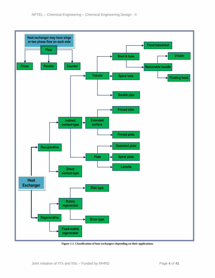
normally classified depending on the transfer process occurring in them. General
classification of heat exchangers is shown in the Figure 1.1.
Amongst of all type of exchangers, shell and tube exchangers are most commonly used
heat exchange equipment. The common types of shell and tube exchangers are:
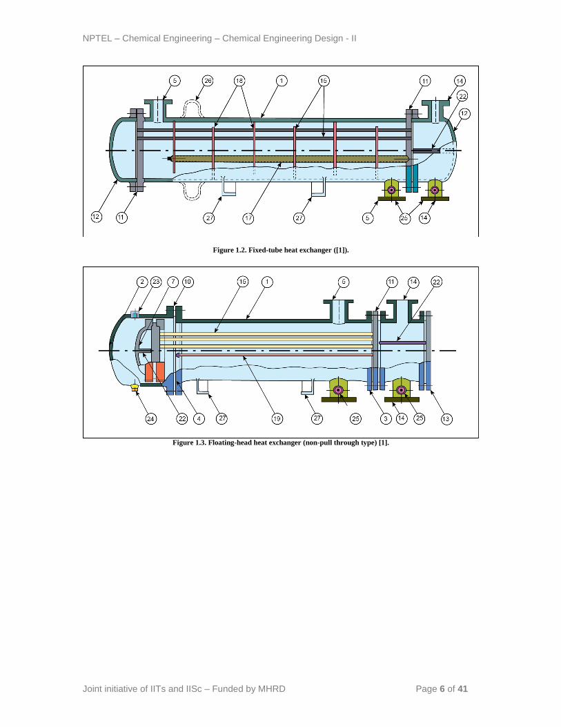
Fixed tube-sheet exchanger (non-removable tube bundle): The simplest and cheapest
type of shell and tube exchanger is with fixed tube sheet design. In this type of
exchangers the tube sheet is welded to the shell and no relative movement between the
shell and tube bundle is possible (Figure 1.2).
Removable tube bundle: Tube bundle may be removed for ease of cleaning and
replacement. Removable tube bundle exchangers further can be categorized in floating-
head and U-tube exchanger.
Floating-head exchanger: It consists of a stationery tube sheet which is
clamped with the shell flange. At the opposite end of the bundle, the tubes
may expand into a freely riding floating-head or floating tube sheet. A
floating head cover is bolted to the tube sheet and the entire bundle can be
removed for cleaning and inspection of the interior. This type of exchanger
is shown in Figure 1.3.
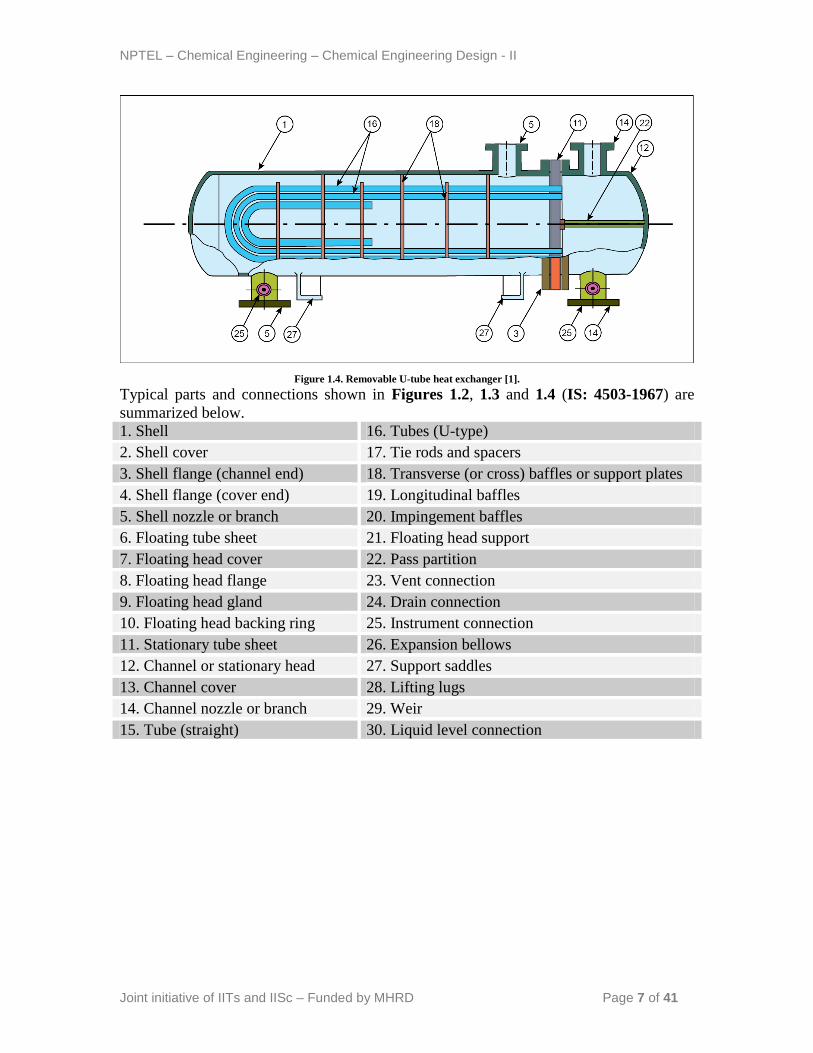
U-tube exchanger: This type of exchangers consists of tubes which are bent
in the form of a „U‟ and rolled back into the tube sheet shown in the Figure
1.4. This means that it will omit some tubes at the centre of the tube bundle
NPTEL – Chemical Engineering – Chemical Engineering Design - II
Joint initiative of IITs and IISc – Funded by MHRD Page 3 of 41
depending on the tube arrangement. The tubes can expand freely towards
the „U‟ bend end.
The different operational and constructional advantages and limitations depending on
applications of shell and tube exchangers are summarized in Table 1.1. TEMA (USA)
and IS: 4503-1967 (India) standards provide the guidelines for the mechanical design of
unfired shell and tube heat exchangers. As shown in the Table 1.1, TEMA 3-digit codes
specify the types of front-end, shell, and rear-end of shell and tube exchangers.
NPTEL – Chemical Engineering – Chemical Engineering Design - II
Joint initiative of IITs and IISc – Funded by MHRD Page 4 of 41
Figure 1.1. Classification of heat exchangers depending on their applications.
Recuperative
Regenerative
Rotary regenerator
Fixed-matrix regenerator
Indirect contact-type
Direct contact-type
Disk type
Drum type
Tubular
Plate
Extended
surface
Double pipe
Spiral tube
Shell & tube
Finned tube
Finned plate
Gasketed plate
Spiral plate
Lamella
Removable bundle
Floating head
Fixed tubesheet
U-tube
Heat Exchanger
Heat exchanger may have singe or two phase flow on each side
Flow
Parallel Counter Cross
NPTEL – Chemical Engineering – Chemical Engineering Design - II
Joint initiative of IITs and IISc – Funded by MHRD Page 5 of 41
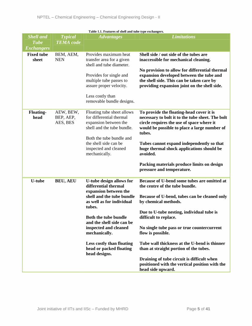
Table 1.1. Features of shell and tube type exchangers.
Shell and
Tube
Exchangers
Typical
TEMA code
Advantages Limitations
Fixed tube
sheet
BEM, AEM,
NEN
Provides maximum heat
transfer area for a given
shell and tube diameter.
Provides for single and
multiple tube passes to
assure proper velocity.
Less costly than
removable bundle designs.
Shell side / out side of the tubes are
inaccessible for mechanical cleaning.
No provision to allow for differential thermal
expansion developed between the tube and
the shell side. This can be taken care by
providing expansion joint on the shell side.
Floating-
head
AEW, BEW,
BEP, AEP,
AES, BES
Floating tube sheet allows
for differential thermal
expansion between the
shell and the tube bundle.
Both the tube bundle and
the shell side can be
inspected and cleaned
mechanically.
To provide the floating-head cover it is
necessary to bolt it to the tube sheet. The bolt
circle requires the use of space where it
would be possible to place a large number of
tubes.
Tubes cannot expand independently so that
huge thermal shock applications should be
avoided.
Packing materials produce limits on design
pressure and temperature.
U-tube BEU, AEU U-tube design allows for
differential thermal
expansion between the
shell and the tube bundle
as well as for individual
tubes.
Both the tube bundle
and the shell side can be
inspected and cleaned
mechanically.
Less costly than floating
head or packed floating
head designs.
Because of U-bend some tubes are omitted at
the centre of the tube bundle.
Because of U-bend, tubes can be cleaned only
by chemical methods.
Due to U-tube nesting, individual tube is
difficult to replace.
No single tube pass or true countercurrent
flow is possible.
Tube wall thickness at the U-bend is thinner
than at straight portion of the tubes.
Draining of tube circuit is difficult when
positioned with the vertical position with the
head side upward.
NPTEL – Chemical Engineering – Chemical Engineering Design - II
Joint initiative of IITs and IISc – Funded by MHRD Page 6 of 41
Figure 1.2. Fixed-tube heat exchanger ([1]).
Figure 1.3. Floating-head heat exchanger (non-pull through type) [1].
NPTEL – Chemical Engineering – Chemical Engineering Design - II
Joint initiative of IITs and IISc – Funded by MHRD Page 7 of 41
Figure 1.4. Removable U-tube heat exchanger [1].
Typical parts and connections shown in Figures 1.2, 1.3 and 1.4 (IS: 4503-1967) are
summarized below.
1. Shell 16. Tubes (U-type)
2. Shell cover 17. Tie rods and spacers
3. Shell flange (channel end) 18. Transverse (or cross) baffles or support plates
4. Shell flange (cover end) 19. Longitudinal baffles
5. Shell nozzle or branch 20. Impingement baffles
6. Floating tube sheet 21. Floating head support
7. Floating head cover 22. Pass partition
8. Floating head flange 23. Vent connection
9. Floating head gland 24. Drain connection
10. Floating head backing ring 25. Instrument connection
11. Stationary tube sheet 26. Expansion bellows
12. Channel or stationary head 27. Support saddles
13. Channel cover 28. Lifting lugs
14. Channel nozzle or branch 29. Weir
15. Tube (straight) 30. Liquid level connection
NPTEL – Chemical Engineering – Chemical Engineering Design - II
Joint initiative of IITs and IISc – Funded by MHRD Page 8 of 41
Lecture 2: Thermal Design Considerations
The flow rates of both hot and cold streams, their terminal temperatures and fluid
properties are the primary inputs of thermal design of heat exchangers.
1.2. Thermal design considerations
Thermal design of a shell and tube heat exchanger typically includes the determination of
heat transfer area, number of tubes, tube length and diameter, tube layout, number of
shell and tube passes, type of heat exchanger (fixed tube sheet, removable tube bundle
etc), tube pitch, number of baffles, its type and size, shell and tube side pressure drop etc.
1.2.1. Shell
Shell is the container for the shell fluid and the tube bundle is placed inside the shell.
Shell diameter should be selected in such a way to give a close fit of the tube bundle.
The clearance between the tube bundle and inner shell wall depends on the type of
exchanger ([2]; page 647). Shells are usually fabricated from standard steel pipe with
satisfactory corrosion allowance. The shell thickness of 3/8 inch for the shell ID of 12-24
inch can be satisfactorily used up to 300 psi of operating pressure.
1.2.2. Tube
Tube OD of ¾ and 1‟‟ are very common to design a compact heat exchanger. The most
efficient condition for heat transfer is to have the maximum number of tubes in the shell
to increase turbulence. The tube thickness should be enough to withstand the internal
pressure along with the adequate corrosion allowance. The tube thickness is expressed in
terms of BWG (Birmingham Wire Gauge) and true outside diameter (OD). The tube
length of 6, 8, 12, 16, 20 and 24 ft are preferably used. Longer tube reduces shell
diameter at the expense of higher shell pressure drop. Finned tubes are also used when
fluid with low heat transfer coefficient flows in the shell side. Stainless steel, admiralty
brass, copper, bronze and alloys of copper-nickel are the commonly used tube materials:

NPTEL – Chemical Engineering – Chemical Engineering Design - II
Joint initiative of IITs and IISc – Funded by MHRD Page 9 of 41
1.2.3. Tube pitch, tube-layout and tube-count
Tube pitch is the shortest centre to centre distance between the adjacent tubes. The tubes
are generally placed in square or triangular patterns (pitch) as shown in the Figure 1.5.
The widely used tube layouts are illustrated in Table 1.2.
The number of tubes that can be accommodated in a given shell ID is called tube count.
The tube count depends on the factors like shell ID, OD of tube, tube pitch, tube layout,
number of tube passes, type of heat exchanger and design pressure.
1.2.4. Tube passes
The number of passes is chosen to get the required tube side fluid velocity to obtain
greater heat transfer co-efficient and also to reduce scale formation. The tube passes vary
from 1 to 16. The tube passes of 1, 2 and 4 are common in application. The partition built
into exchanger head known as partition plate (also called pass partition) is used to direct
the tube side flow.
Table 1.2. Common tube layouts.
Tube OD, in Pitch type Tube pitch, in 3 4 Square 1
1 114
3 4 Triangular 1516
3 4 1
Figure 1.5. Heat exchanger tube-layouts.
+
+
+
+
Flow
Pitch
+ +
Flow
Pitch
+
+
+
+
+ Flow
Pitch
a). Square b). Triangular c). Rotated square
NPTEL – Chemical Engineering – Chemical Engineering Design - II
Joint initiative of IITs and IISc – Funded by MHRD Page 10 of 41
1.2.5. Tube sheet
The tubes are fixed with tube sheet that form the barrier between the tube and shell fluids.
The tubes can be fixed with the tube sheet using ferrule and a soft metal packing ring.
The tubes are attached to tube sheet with two or more grooves in the tube sheet wall by
„tube rolling‟. The tube metal is forced to move into the grooves forming an excellent
tight seal. This is the most common type of fixing arrangement in large industrial
exchangers. The tube sheet thickness should be greater than the tube outside diameter to
make a good seal. The recommended standards (IS:4503 or TEMA) should be followed
to select the minimum tube sheet thickness.
NPTEL – Chemical Engineering – Chemical Engineering Design - II
Joint initiative of IITs and IISc – Funded by MHRD Page 11 of 41
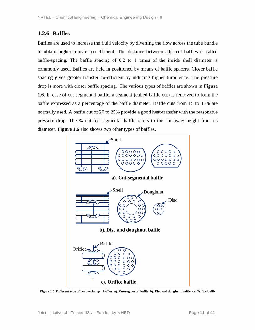
1.2.6. Baffles
Baffles are used to increase the fluid velocity by diverting the flow across the tube bundle
to obtain higher transfer co-efficient. The distance between adjacent baffles is called
baffle-spacing. The baffle spacing of 0.2 to 1 times of the inside shell diameter is
commonly used. Baffles are held in positioned by means of baffle spacers. Closer baffle
spacing gives greater transfer co-efficient by inducing higher turbulence. The pressure
drop is more with closer baffle spacing. The various types of baffles are shown in Figure
1.6. In case of cut-segmental baffle, a segment (called baffle cut) is removed to form the
baffle expressed as a percentage of the baffle diameter. Baffle cuts from 15 to 45% are
normally used. A baffle cut of 20 to 25% provide a good heat-transfer with the reasonable
pressure drop. The % cut for segmental baffle refers to the cut away height from its
diameter. Figure 1.6 also shows two other types of baffles.
Figure 1.6. Different type of heat exchanger baffles: a). Cut-segmental baffle, b). Disc and doughnut baffle, c). Orifice baffle
Orifice
Shell
Shell Doughnut
Disc
Baffle
a). Cut-segmental baffle
b). Disc and doughnut baffle
c). Orifice baffle
NPTEL – Chemical Engineering – Chemical Engineering Design - II
Joint initiative of IITs and IISc – Funded by MHRD Page 12 of 41
1.2.7. Fouling Considerations
The most of the process fluids in the exchanger foul the heat transfer surface. The
material deposited reduces the effective heat transfer rate due to relatively low thermal
conductivity. Therefore, net heat transfer with clean surface should be higher to
compensate the reduction in performance during operation. Fouling of exchanger
increases the cost of (i) construction due to oversizing, (ii) additional energy due to poor
exchanger performance and (iii) cleaning to remove deposited materials. A spare
exchanger may be considered in design for uninterrupted services to allow cleaning of
exchanger.
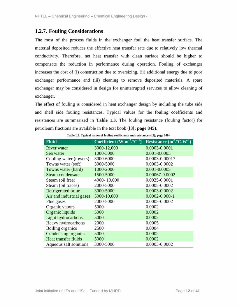
The effect of fouling is considered in heat exchanger design by including the tube side
and shell side fouling resistances. Typical values for the fouling coefficients and
resistances are summarized in Table 1.3. The fouling resistance (fouling factor) for
petroleum fractions are available in the text book ([3]; page 845).
Table 1.3. Typical values of fouling coefficients and resistances ([2]; page 640).
Fluid Coefficient (W.m-2
.°C-1
) Resistance (m2.°C.W
-1)
River water 3000-12,000 0.0003-0.0001
Sea water 1000-3000 0.001-0.0003
Cooling water (towers) 3000-6000 0.0003-0.00017
Towns water (soft) 3000-5000 0.0003-0.0002
Towns water (hard) 1000-2000 0.001-0.0005
Steam condensate 1500-5000 0.00067-0.0002
Steam (oil free) 4000- 10,000 0.0025-0.0001
Steam (oil traces) 2000-5000 0.0005-0.0002
Refrigerated brine 3000-5000 0.0003-0.0002
Air and industrial gases 5000-10,000 0.0002-0.000-1
Flue gases 2000-5000 0.0005-0.0002
Organic vapors 5000 0.0002
Organic liquids 5000 0.0002
Light hydrocarbons 5000 0.0002
Heavy hydrocarbons 2000 0.0005
Boiling organics 2500 0.0004
Condensing organics 5000 0.0002
Heat transfer fluids 5000 0.0002
Aqueous salt solutions 3000-5000 0.0003-0.0002
NPTEL – Chemical Engineering – Chemical Engineering Design - II
Joint initiative of IITs and IISc – Funded by MHRD Page 13 of 41
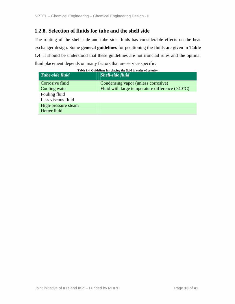
1.2.8. Selection of fluids for tube and the shell side
The routing of the shell side and tube side fluids has considerable effects on the heat
exchanger design. Some general guidelines for positioning the fluids are given in Table
1.4. It should be understood that these guidelines are not ironclad rules and the optimal
fluid placement depends on many factors that are service specific.
Table 1.4. Guidelines for placing the fluid in order of priority
Tube-side fluid Shell-side fluid
Corrosive fluid Condensing vapor (unless corrosive)
Cooling water Fluid with large temperature difference (>40°C)
Fouling fluid
Less viscous fluid
High-pressure steam
Hotter fluid
NPTEL – Chemical Engineering – Chemical Engineering Design - II
Joint initiative of IITs and IISc – Funded by MHRD Page 14 of 41
Lecture 3: Process (Thermal) Design Procedure
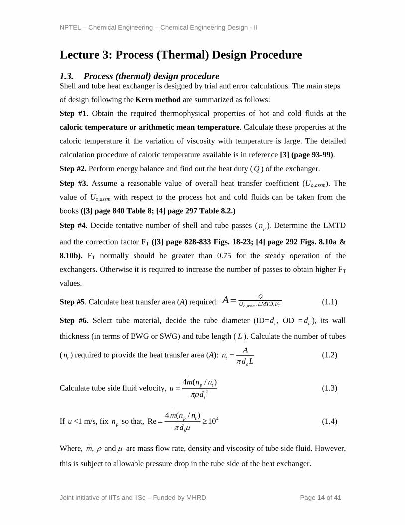
1.3. Process (thermal) design procedure Shell and tube heat exchanger is designed by trial and error calculations. The main steps
of design following the Kern method are summarized as follows:
Step #1. Obtain the required thermophysical properties of hot and cold fluids at the
caloric temperature or arithmetic mean temperature. Calculate these properties at the
caloric temperature if the variation of viscosity with temperature is large. The detailed
calculation procedure of caloric temperature available is in reference [3] (page 93-99).
Step #2. Perform energy balance and find out the heat duty ( Q ) of the exchanger.
Step #3. Assume a reasonable value of overall heat transfer coefficient (Uo,assm). The
value of Uo,assm with respect to the process hot and cold fluids can be taken from the
books ([3] page 840 Table 8; [4] page 297 Table 8.2.)
Step #4. Decide tentative number of shell and tube passes ( pn ). Determine the LMTD
and the correction factor FT ([3] page 828-833 Figs. 18-23; [4] page 292 Figs. 8.10a &
8.10b). FT normally should be greater than 0.75 for the steady operation of the
exchangers. Otherwise it is required to increase the number of passes to obtain higher FT
values.
Step #5. Calculate heat transfer area (A) required: , . .o assm T
Q
U LMTD FA (1.1)
Step #6. Select tube material, decide the tube diameter (ID= id , OD = od ), its wall
thickness (in terms of BWG or SWG) and tube length ( L ). Calculate the number of tubes
( tn ) required to provide the heat transfer area (A): t
o
An
d L (1.2)
Calculate tube side fluid velocity,
.
2
4 ( / )p t
i
m n nu
d (1.3)
If u <1 m/s, fix pn so that,
.
44 ( / )
Re 10p t
i
m n n
d (1.4)
Where, .
, and m are mass flow rate, density and viscosity of tube side fluid. However,
this is subject to allowable pressure drop in the tube side of the heat exchanger.
NPTEL – Chemical Engineering – Chemical Engineering Design - II
Joint initiative of IITs and IISc – Funded by MHRD Page 15 of 41
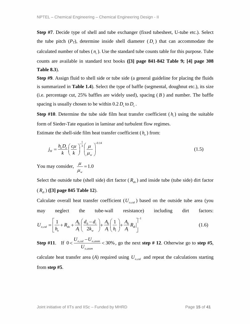
Step #7. Decide type of shell and tube exchanger (fixed tubesheet, U-tube etc.). Select
the tube pitch (PT), determine inside shell diameter ( sD ) that can accommodate the
calculated number of tubes ( tn ). Use the standard tube counts table for this purpose. Tube
counts are available in standard text books ([3] page 841-842 Table 9; [4] page 308
Table 8.3).
Step #9. Assign fluid to shell side or tube side (a general guideline for placing the fluids
is summarized in Table 1.4). Select the type of baffle (segmental, doughnut etc.), its size
(i.e. percentage cut, 25% baffles are widely used), spacing ( B ) and number. The baffle
spacing is usually chosen to be within 0.2 sD to sD .
Step #10. Determine the tube side film heat transfer coefficient ( ih ) using the suitable
form of Sieder-Tate equation in laminar and turbulent flow regimes.
Estimate the shell-side film heat transfer coefficient ( oh ) from:
1 0.143
o eH
w
h D cj
k k
(1.5)
You may consider, 1.0w
Select the outside tube (shell side) dirt factor ( doR ) and inside tube (tube side) dirt factor
( diR ) ([3] page 845 Table 12).
Calculate overall heat transfer coefficient ( ,o calU ) based on the outside tube area (you
may neglect the tube-wall resistance) including dirt factors:
1
0 0 0 0,
1 1
2
io cal do di
o i w i i i
A d d A AU R R
h A k A h A
(1.6)
Step #11. If , ,
,
0 30%o cal o assm
o assm
U U
U
, go the next step # 12. Otherwise go to step #5,
calculate heat transfer area (A) required using ,o calU and repeat the calculations starting
from step #5.
NPTEL – Chemical Engineering – Chemical Engineering Design - II
Joint initiative of IITs and IISc – Funded by MHRD Page 16 of 41
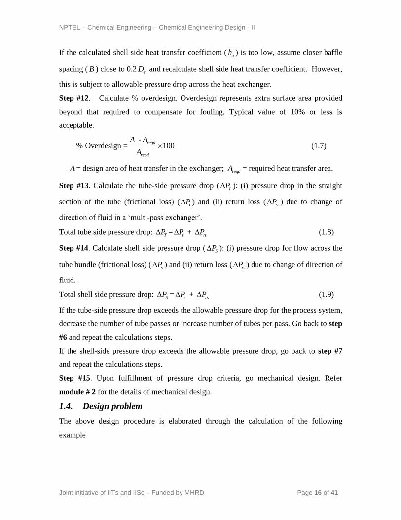
If the calculated shell side heat transfer coefficient ( oh ) is too low, assume closer baffle
spacing ( B ) close to 0.2 sD and recalculate shell side heat transfer coefficient. However,
this is subject to allowable pressure drop across the heat exchanger.
Step #12. Calculate % overdesign. Overdesign represents extra surface area provided
beyond that required to compensate for fouling. Typical value of 10% or less is
acceptable.
-% Overdesign = 100
reqd
reqd
A A
A (1.7)
A = design area of heat transfer in the exchanger; reqdA = required heat transfer area.
Step #13. Calculate the tube-side pressure drop ( TP ): (i) pressure drop in the straight
section of the tube (frictional loss) ( tP ) and (ii) return loss ( rtP ) due to change of
direction of fluid in a „multi-pass exchanger‟.
Total tube side pressure drop: TP = tP + rtP (1.8)
Step #14. Calculate shell side pressure drop ( SP ): (i) pressure drop for flow across the
tube bundle (frictional loss) ( sP ) and (ii) return loss ( rsP ) due to change of direction of
fluid.
Total shell side pressure drop: SP = sP + rsP (1.9)
If the tube-side pressure drop exceeds the allowable pressure drop for the process system,
decrease the number of tube passes or increase number of tubes per pass. Go back to step
#6 and repeat the calculations steps.
If the shell-side pressure drop exceeds the allowable pressure drop, go back to step #7
and repeat the calculations steps.
Step #15. Upon fulfillment of pressure drop criteria, go mechanical design. Refer
module # 2 for the details of mechanical design.
1.4. Design problem
The above design procedure is elaborated through the calculation of the following
example
NPTEL – Chemical Engineering – Chemical Engineering Design - II
Joint initiative of IITs and IISc – Funded by MHRD Page 17 of 41
Lecture 4: Design Problem
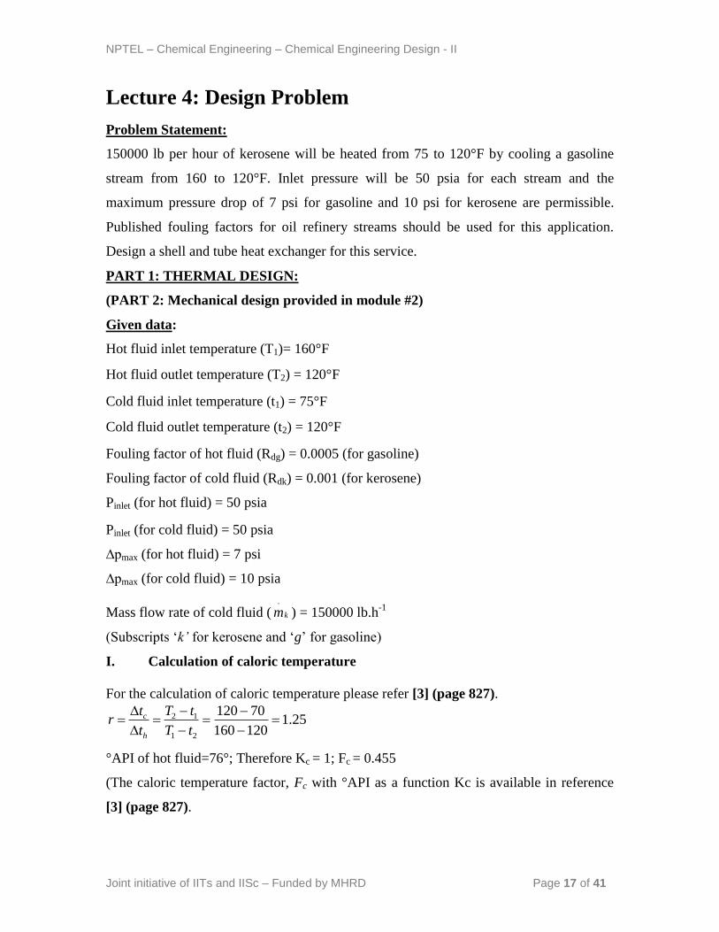
Problem Statement:
150000 lb per hour of kerosene will be heated from 75 to 120°F by cooling a gasoline
stream from 160 to 120°F. Inlet pressure will be 50 psia for each stream and the
maximum pressure drop of 7 psi for gasoline and 10 psi for kerosene are permissible.
Published fouling factors for oil refinery streams should be used for this application.
Design a shell and tube heat exchanger for this service.
PART 1: THERMAL DESIGN:
(PART 2: Mechanical design provided in module #2)
Given data:
Hot fluid inlet temperature (T1)= 160°F
Hot fluid outlet temperature (T2) = 120°F
Cold fluid inlet temperature (t1) = 75°F
Cold fluid outlet temperature (t2) = 120°F
Fouling factor of hot fluid (Rdg) = 0.0005 (for gasoline)
Fouling factor of cold fluid (Rdk) = 0.001 (for kerosene)
Pinlet (for hot fluid) = 50 psia
Pinlet (for cold fluid) = 50 psia
∆pmax (for hot fluid) = 7 psi
∆pmax (for cold fluid) = 10 psia
Mass flow rate of cold fluid ( km.
) = 150000 lb.h-1
(Subscripts „k’ for kerosene and „g‟ for gasoline)
I. Calculation of caloric temperature
For the calculation of caloric temperature please refer [3] (page 827).
25.1120160
70120
21
12
tT
tT
t
tr
h
c
°API of hot fluid=76°; Therefore Kc = 1; Fc = 0.455
(The caloric temperature factor, Fc with °API as a function Kc is available in reference
[3] (page 827).
NPTEL – Chemical Engineering – Chemical Engineering Design - II
Joint initiative of IITs and IISc – Funded by MHRD Page 18 of 41
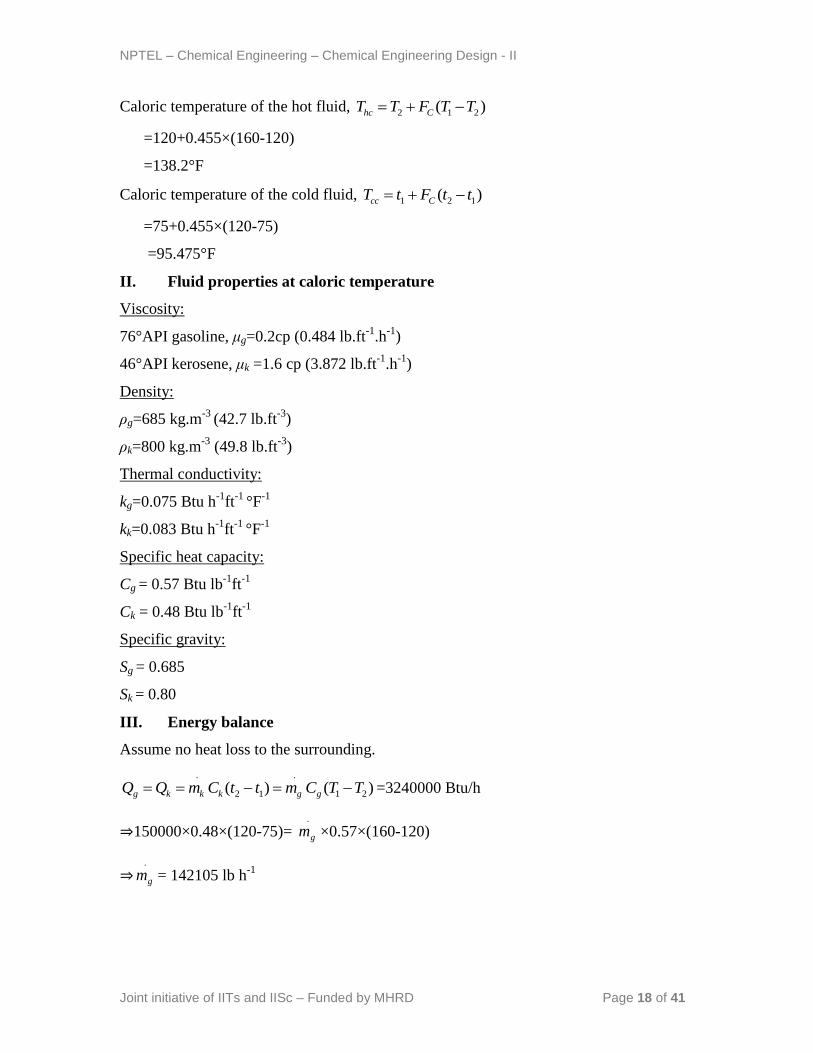
Caloric temperature of the hot fluid, 2 1 2( )hc CT T F T T
=120+0.455×(160-120)
=138.2°F
Caloric temperature of the cold fluid, 1 2 1( )cc CT t F t t
=75+0.455×(120-75)
=95.475°F
II. Fluid properties at caloric temperature
Viscosity:
76°API gasoline, μg=0.2cp (0.484 lb.ft-1
.h-1
)
46°API kerosene, μk =1.6 cp (3.872 lb.ft-1
.h-1
)
Density:
ρg=685 kg.m-3
(42.7 lb.ft-3
)
ρk=800 kg.m-3
(49.8 lb.ft-3
)
Thermal conductivity:
kg=0.075 Btu h-1
ft-1
°F-1
kk=0.083 Btu h-1
ft-1
°F-1
Specific heat capacity:
Cg = 0.57 Btu lb-1
ft-1
Ck = 0.48 Btu lb-1
ft-1
Specific gravity:
Sg = 0.685
Sk = 0.80
III. Energy balance
Assume no heat loss to the surrounding.
)()( 21
.
12
.
TTCmttCmQQ ggkkkg =3240000 Btu/h
⇒150000×0.48×(120-75)= .
gm ×0.57×(160-120)
⇒.
gm = 142105 lb h-1
NPTEL – Chemical Engineering – Chemical Engineering Design - II
Joint initiative of IITs and IISc – Funded by MHRD Page 19 of 41
IV. Calculation of heat transfer area and tube numbers
Iteration #1:
The first iteration is started assuming 1 shell pass and 2 tube pass shell and tube
exchanger with following dimensions and considerations.
Fixed tube plate
1´´ OD tubes (do) (14 BWG) on 1¼´´ square pitch (PT)
Outer diameter of tube= 1´´
Tube length (Lt) =16´
Tube ID (di) = 0.834´´
Fluid arrangement: Kerosene is placed in tube side because it has the higher
fouling tendency
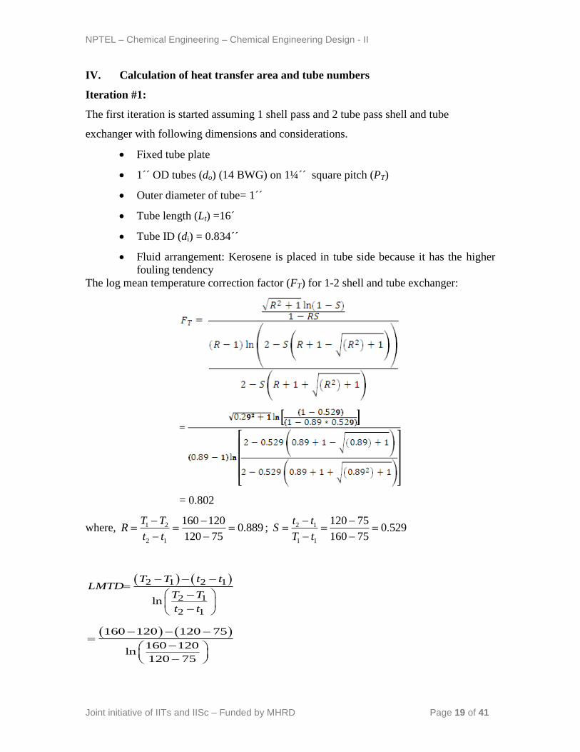
The log mean temperature correction factor (FT) for 1-2 shell and tube exchanger:
= 0.802
where, 889.075120
120160
12
21
tt
TTR ; 529.0
75160
75120
11
12
tT
ttS
2 1 2 1
2 1
2 1
ln
T T t tLMTD
T T
t t
160 120 120 75
160 120ln
120 75
NPTEL – Chemical Engineering – Chemical Engineering Design - II
Joint initiative of IITs and IISc – Funded by MHRD Page 20 of 41
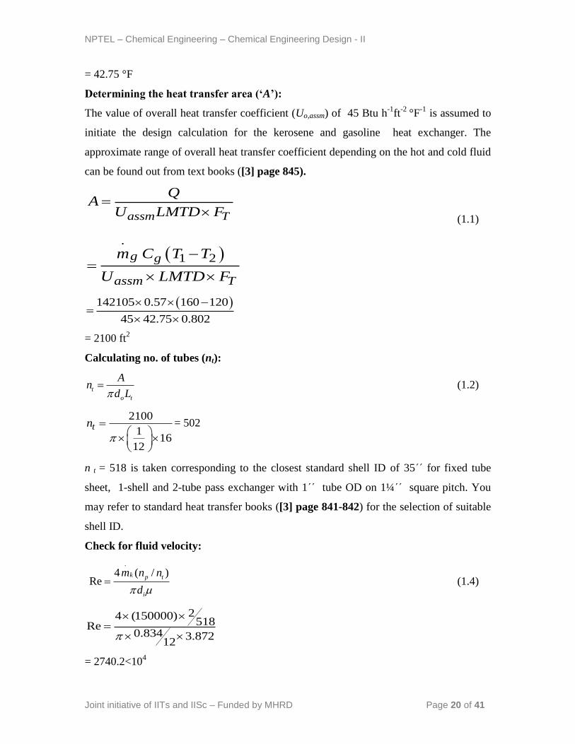
= 42.75 °F
Determining the heat transfer area (‘A’):
The value of overall heat transfer coefficient (Uo,assm) of 45 Btu h-1
ft-2
°F-1
is assumed to
initiate the design calculation for the kerosene and gasoline heat exchanger. The
approximate range of overall heat transfer coefficient depending on the hot and cold fluid
can be found out from text books ([3] page 845).
assm T
QA
U LMTD F
(1.1)
.
1 2g g
assm T
m C T T
U LMTD F
142105 0.57 160 120
45 42.75 0.802
= 2100 ft2
Calculating no. of tubes (nt):
t
o t
An
d L (1.2)
2100
116
12
tn
= 502
n t = 518 is taken corresponding to the closest standard shell ID of 35΄΄ for fixed tube
sheet, 1-shell and 2-tube pass exchanger with 1΄΄ tube OD on 1¼΄΄ square pitch. You
may refer to standard heat transfer books ([3] page 841-842) for the selection of suitable
shell ID.
Check for fluid velocity:
.
4 ( / )Re
k p t
i
m n n
d (1.4)
24 (150000)518Re
0.834 3.87212
= 2740.2<104
NPTEL – Chemical Engineering – Chemical Engineering Design - II
Joint initiative of IITs and IISc – Funded by MHRD Page 21 of 41
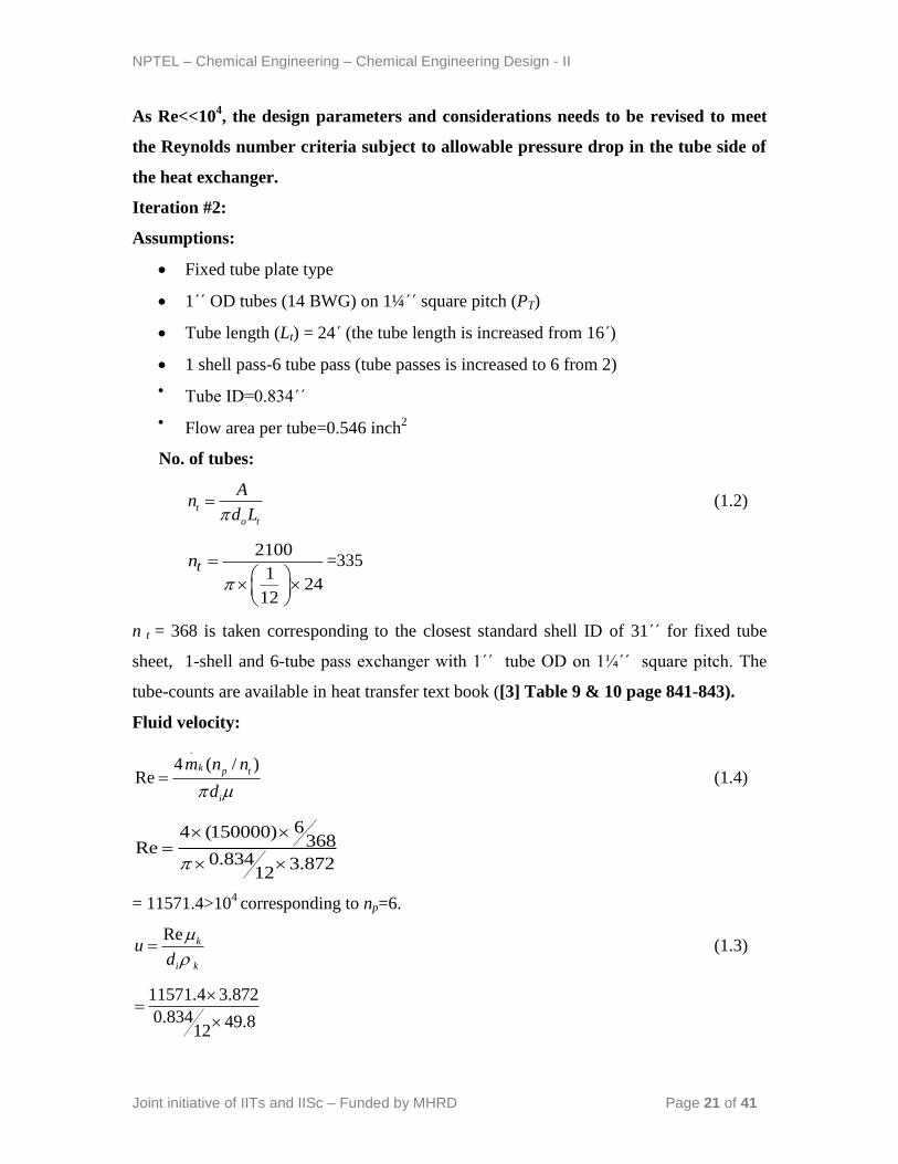
As Re<<104, the design parameters and considerations needs to be revised to meet
the Reynolds number criteria subject to allowable pressure drop in the tube side of
the heat exchanger.
Iteration #2:
Assumptions:
Fixed tube plate type
1΄΄ OD tubes (14 BWG) on 1¼΄΄ square pitch (PT)
Tube length (Lt) = 24΄ (the tube length is increased from 16΄)
1 shell pass-6 tube pass (tube passes is increased to 6 from 2)
Tube ID=0.834΄΄
Flow area per tube=0.546 inch2
No. of tubes:
t
o t
An
d L (1.2)
2100
124
12
tn
=335
n t = 368 is taken corresponding to the closest standard shell ID of 31΄΄ for fixed tube
sheet, 1-shell and 6-tube pass exchanger with 1΄΄ tube OD on 1¼΄΄ square pitch. The
tube-counts are available in heat transfer text book ([3] Table 9 & 10 page 841-843).
Fluid velocity:
.
4 ( / )Re
k p t
i
m n n
d (1.4)
64 (150000)368Re
0.834 3.87212
= 11571.4>104
corresponding to np=6.
Re k
i k
ud
(1.3)
11571.4 3.872
0.834 49.812
NPTEL – Chemical Engineering – Chemical Engineering Design - II
Joint initiative of IITs and IISc – Funded by MHRD Page 22 of 41
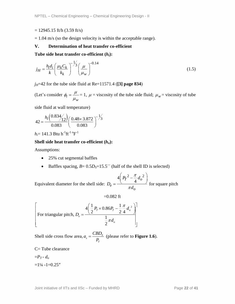
= 12945.15 ft/h (3.59 ft/s)
= 1.04 m/s (so the design velocity is within the acceptable range).
V. Determination of heat transfer co-efficient
Tube side heat transfer co-efficient (hi):
1 0.143
i i k kH
k w
h d Cj
k k
(1.5)
jH=42 for the tube side fluid at Re=11571.4 ([3] page 834)
(Let‟s consider tw
= 1, = viscosity of the tube side fluid; w = viscosity of tube
side fluid at wall temperature)
13
0.8340.48 3.87212
420.083 0.083
ih
hi= 141.3 Btu h-1
ft-1 o
F-1
Shell side heat transfer co-efficient (ho):
Assumptions:
25% cut segmental baffles
Baffles spacing, B= 0.5DS=15.5΄΄ (half of the shell ID is selected)
Equivalent diameter for the shell side:
2 244
T o
eo
P d
Dd
for square pitch
=0.082 ft
21 14 0.86
2 2 4For triangular pitch,
1
2
T T o
e
o
P P d
D
d
Shell side cross flow area, Ss
T
CBDa
P (please refer to Figure 1.6).
C= Tube clearance
=PT - do
=1¼ -1=0.25″
NPTEL – Chemical Engineering – Chemical Engineering Design - II
Joint initiative of IITs and IISc – Funded by MHRD Page 23 of 41
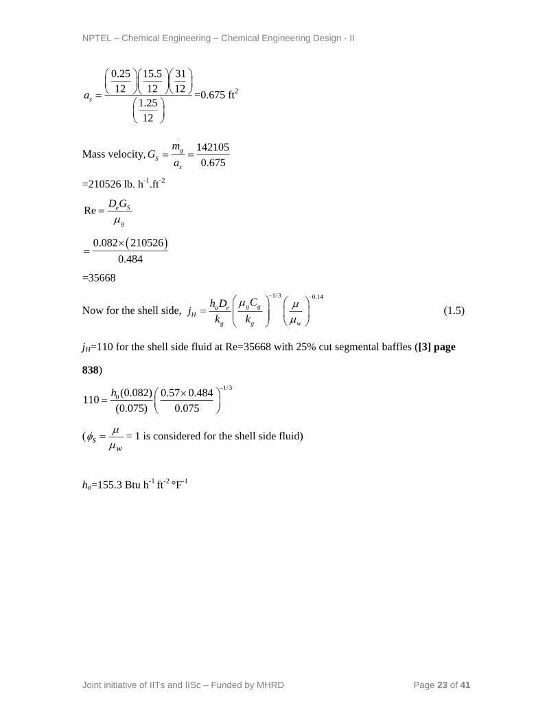
0.25 15.5 31
12 12 12
1.25
12
sa
=0.675 ft2
Mass velocity,
.
142105
0.675
g
S
s
mG
a
=210526 lb. h-1
.ft-2
Re e S
g
D G
0.082 210526
0.484
=35668
Now for the shell side,
1/3 0.14
g go eH
g g w
Ch Dj
k k
(1.5)
jH=110 for the shell side fluid at Re=35668 with 25% cut segmental baffles ([3] page
838)
1/3
0 (0.082) 0.57 0.484110
(0.075) 0.075
h
( sw
= 1 is considered for the shell side fluid)
ho=155.3 Btu h-1
ft-2
°F-1
NPTEL – Chemical Engineering – Chemical Engineering Design - II
Joint initiative of IITs and IISc – Funded by MHRD Page 24 of 41
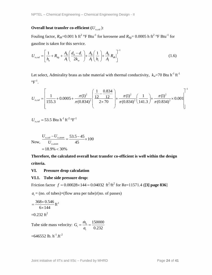
Overall heat transfer co-efficient ( ,o calU ):
Fouling factor, Rdk=0.001 h ft2 °F Btu
-1 for kerosene and Rdg= 0.0005 h ft
2 °F Btu
-1 for
gasoline is taken for this service.
1
0 0 0 0,
1 1
2
io cal dg dk
o i w i i i
A d d A AU R R
h A k A h A
(1.6)
Let select, Admirality brass as tube material with thermal conductivity, kw=70 Btu h-1
ft-1
°F-1
.
1
2 2 2
, 2 2 2
1 0.8341 (1) (1) 1 (1)12 120.0005 0.001
155.3 (0.834) 2 70 (0.834) 141.3 (0.834)o calU
,o calU 53.5 Btu h-1
ft-2
°F-1
Now,
, ,
,
53.5 45100
45
18.9% 30%
o cal o assm
o assm
U U
U
Therefore, the calculated overall heat transfer co-efficient is well within the design
criteria.
VI. Pressure drop calculation
VI.1. Tube side pressure drop:
Friction factor 0.00028 144 0.04032f ft2/ft
2 for Re=11571.4 ([3] page 836]
ta = (no. of tubes)×(flow area per tube)/(no. of passes)
2368 0.546ft
6 144
=0.232 ft2
Tube side mass velocity: 150000
0.232
kt
t
mG
a
=646552 lb. h-1
.ft-2
NPTEL – Chemical Engineering – Chemical Engineering Design - II
Joint initiative of IITs and IISc – Funded by MHRD Page 25 of 41
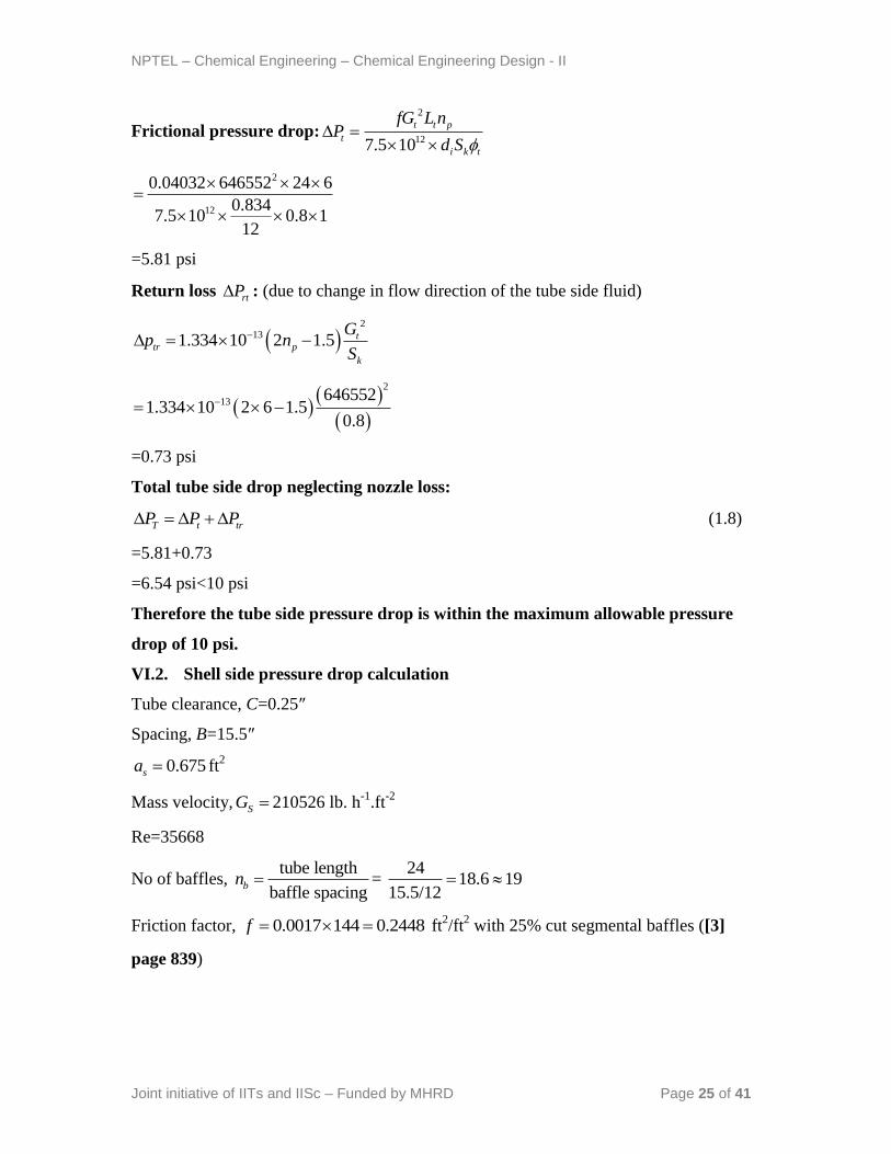
Frictional pressure drop:
2
127.5 10
t t p
t
i k t
fG L nP
d S
2
12
0.04032 646552 24 6
0.8347.5 10 0.8 1
12
=5.81 psi
Return loss rtP : (due to change in flow direction of the tube side fluid)
2
131.334 10 2 1.5 ttr p
k
Gp n
S
2
13646552
1.334 10 2 6 1.50.8
=0.73 psi
Total tube side drop neglecting nozzle loss:
T t trP P P (1.8)
=5.81+0.73
=6.54 psi<10 psi
Therefore the tube side pressure drop is within the maximum allowable pressure
drop of 10 psi.
VI.2. Shell side pressure drop calculation
Tube clearance, C=0.25″
Spacing, B=15.5″
0.675sa ft2
Mass velocity, SG 210526 lb. h-1
.ft-2
Re=35668
No of baffles, tube length 24
= 18.6 19baffle spacing 15.5/12
bn
Friction factor, 0.0017 144 0.2448f ft2/ft
2 with 25% cut segmental baffles ([3]
page 839)
NPTEL – Chemical Engineering – Chemical Engineering Design - II
Joint initiative of IITs and IISc – Funded by MHRD Page 26 of 41
Shell side frictional pressure drop sP :
2
12
1
7.5 10
s S b
s
e k k
fG D nP
D S
2
12
310.2376 210526 19 1
12
7.5 10 0.082 0.685 1
=1.4 psi <7 psi
0rsP (in case of single shell pass flow)
Total shell side drop neglecting nozzle loss:
S s srP P P =1.4 psi (1.9)
Therefore the shell side pressure drop is within the maximum allowable pressure
drop of 7 psi.
VII. Over surface and over design
Over surface =,C o cal
C
U U
U
The clean overall heat fransfer co-efficient: o io
o io
C
h hU
h h
iio i
o
dh h
d =141.3×0.834=117.8 Btu h
-1 ft
-2 °F
-1
CU =66.98 Btu h -1
ft-2
°F-1
% Over surface =66.98 53.5
10066.98
=20% (acceptable)
Over design:
-% Overdesign = 100
reqd
reqd
A A
A (1.7)
The design area of heat transfer in the exchanger ( tn =318):
o t tA d L n =π×12
1×24×368=2312 ft
2
NPTEL – Chemical Engineering – Chemical Engineering Design - II
Joint initiative of IITs and IISc – Funded by MHRD Page 27 of 41
The required heat transfer area (where, tn =335):
reqd o t tA d L n = π×12
1×24×335=2105 ft
2
% Overdesign =9.8% which is within the acceptable limit.
Refer module # 2 for the mechanical design of shell and tube heat exchanger.
Lecture 5: Shell and Tube Exchanger for Two Phase Heat Transfer
2. PROCESS DESIGN OF SHELL AND TUBE
EXCHANGER FOR TWO PHASE HEAT TRANSFER
2.1. Condenser
The change from liquid phase to vapor phase is called vaporization and the reverse phase
transfer is condensation. The change from liquid to vapor or vapor to liquid occurs at one
temperature (called saturation or equilibrium temperature) for a pure fluid compound at a
given pressure. The industrial practice of vaporization and condensation occurs at almost
constant pressure; therefore the phase change occurs isothermally.
Condensation occurs by two different physical mechanisms i.e. drop-wise condensation
and film condensation.
The nature of the condensation depends upon whether the condensate (liquid formed
from vapor) wets or does not wet the solid surface. If the condensate wets the surface and
flows on the surface in the form of a film, it is called film condensation. When the
condensate does not wet the solid surface and the condensate is accumulated in the form
of droplets, is drop-wise condensation. Heat transfer coefficient is about 4 to 8 times
higher for drop wise condensation. The condensate forms a liquid film on the bare-
surface in case of film condensation. The heat transfer coefficient is lower for film
condensation due to the resistance of this liquid film.
Dropwise condensation occurs usually on new, clean and polished surfaces. The heat
exchanger used for condensation is called condenser. In industrial condensers, film
condensation normally occurs.
NPTEL – Chemical Engineering – Chemical Engineering Design - II
Joint initiative of IITs and IISc – Funded by MHRD Page 28 of 41
2.1.1. Types of condensers
There two general types of condensers:
i. Vertical condenser
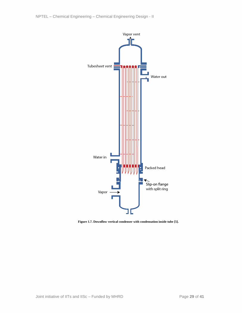
Downflow vertical condenser: The vapor enters at the top of condenser and flows
down inside tubes. The condensate drains from the tubes by gravity and vapor
induced shear (Figure 1.7).
Upflow vertical condenser: In case of upflow condenser, the vapor enters at the
bottom and flows upwards inside the tubes. The condensate drains down the tubes
by gravity only.
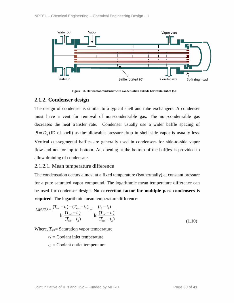
ii. Horizontal condenser: The condensation may occur inside or outside the
horizontal tubes (Figure 1.8). Condensation in the tube-side is common in air-
cooled condensers. The main disadvantage of this type of condenser is that the
liquid tends to build up in the tubes. Therefore the effective heat transfer co-
efficient is reduced significantly.
NPTEL – Chemical Engineering – Chemical Engineering Design - II
Joint initiative of IITs and IISc – Funded by MHRD Page 29 of 41
Figure 1.7. Downflow vertical condenser with condensation inside tube [5].
NPTEL – Chemical Engineering – Chemical Engineering Design - II
Joint initiative of IITs and IISc – Funded by MHRD Page 30 of 41
Figure 1.8. Horizontal condenser with condensation outside horizontal tubes [5].
2.1.2. Condenser design
The design of condenser is similar to a typical shell and tube exchangers. A condenser
must have a vent for removal of non-condensable gas. The non-condensable gas
decreases the heat transfer rate. Condenser usually use a wider baffle spacing of
sB D (ID of shell) as the allowable pressure drop in shell side vapor is usually less.
Vertical cut-segmental baffles are generally used in condensers for side-to-side vapor
flow and not for top to bottom. An opening at the bottom of the baffles is provided to
allow draining of condensate.
2.1.2.1. Mean temperature difference
The condensation occurs almost at a fixed temperature (isothermally) at constant pressure
for a pure saturated vapor compound. The logarithmic mean temperature difference can
be used for condenser design. No correction factor for multiple pass condensers is
required. The logarithmic mean temperature difference:
1 2 2 1
1 1
2 2
( ) ( ) ( )
( ) ( )ln ln
( ) ( )
sat sat
sat sat
sat sat
T t T t t tLMTD
T t T t
T t T t
(1.10)
Where, Tsat= Saturation vapor temperature
t1 = Coolant inlet temperature
t2 = Coolant outlet temperature
NPTEL – Chemical Engineering – Chemical Engineering Design - II
Joint initiative of IITs and IISc – Funded by MHRD Page 31 of 41
2.1.2.2. Calculation of heat transfer co-efficient during condensation
Calculation of tube side heat transfer co-efficient (hi): The calculation of heat transfer
co-efficient for the cold fluid (coolant) can be performed similarly as discussed in design
of shell and tube heat exchanger (heat transfer without phase change). Here it is assumed
that the coolant flows the in tube side and the condensing saturated vapor flows in the
shell side. If the condensation occurs in the tube side, follow the procedure discussed in
next section for shell side calculation.
Calculation of shell-side heat transfer coefficient (condensing film heat transfer
coefficient) (ho): The Kern method is discussed here to calculate the individual heat
transfer co-efficient of the condensing fluid by trial and error calculation.
i. Assume, ( )o assmh in the range from 100 to 300 BTU.h-1
.ft-2
.°F-1
. The film
coefficient of condensing hydrocarbons generally varies in this range. Air-free
condensing steam has a coefficient of 1500 BTU.h-1
.ft-2
.°F-1
.
ii. Calculate the tube wall temperature ( wT ):
( )
( )
( )
( )
o v C avg
w C avg
io o
h T TT T
h h
(1.11)
or
( )
( )
o v ccw cc
io o
h T TT T
h h
(1.12)
Where, iio i
io
dh h
d ( id tube ID and od tube OD)
( )C avgT = Average temperature of the cold fluid
ccT =Caloric temperature of the cold fluid
iii. Calculate condensate film temperature, ( )
2
w vf
T TT
(1.13)
vT =Condensation temperature (For pure fluid compound vT is the saturation temperature.
Average of condensation over a temperature range also can be used for non-isothermal
condensation).
NPTEL – Chemical Engineering – Chemical Engineering Design - II
Joint initiative of IITs and IISc – Funded by MHRD Page 32 of 41
iv. Calculate all thermophysical property of the condensing fluid at film temperature
( fT ).
v. Recalculate, ( )o calh from jH factor.
Now again set, ( ) ( )o assm o calh h and continue the calculation till ( ) ( )o assm o calh h .
vi. Calculate the overall heat transfer-coefficient ( dU ) including the dirt factors.
NPTEL – Chemical Engineering – Chemical Engineering Design - II
Joint initiative of IITs and IISc – Funded by MHRD Page 33 of 41
Lecture 6: Condenser and Reboiler Design
2.1.2.3. Pressure drop calculation
i. Tube side pressure drop
In case of tube side condensation:
For condensation in the tube side by taking one-half of the conventional pressure drop
relation can be used.
2
12
1
2 7.5 10
t t p
t
i t t
fG L nP
d S
, psi (1.14)
Where,
f = friction factor
tG =mass velocity [lb. h-1
.ft-2
]
tL =Tube length [ft]
pn =Number of tube passes
id =Tube ID [ft]
tS =Specific gravity of the tube side fluid
t =Viscosity correction factor
( tw
= 1, = viscosity of the tube side fluid; w = viscosity of water)
ii. Shell side pressure drop
In case of shell side condensation: Similarly for condensation in the shell side:
2
12
11
2 7.5 10
s S b
s
e s s
fG D nP
D S
, psi (1.15)
Subscript „s‟ indicates shell side fluid.
bn = number of baffles
eD = Equivalent diameter for the shell [ft]
NPTEL – Chemical Engineering – Chemical Engineering Design - II
Joint initiative of IITs and IISc – Funded by MHRD Page 34 of 41
Calculate all fluid property at film temperature fT . No return loss calculation is
required for the condensing fluid.
In case of non-condensing fluid (single phase flow), use the conventional pressure
drop relation.
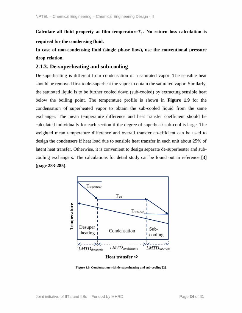
2.1.3. De-superheating and sub-cooling
De-superheating is different from condensation of a saturated vapor. The sensible heat
should be removed first to de-superheat the vapor to obtain the saturated vapor. Similarly,
the saturated liquid is to be further cooled down (sub-cooled) by extracting sensible heat
below the boiling point. The temperature profile is shown in Figure 1.9 for the
condensation of superheated vapor to obtain the sub-cooled liquid from the same
exchanger. The mean temperature difference and heat transfer coefficient should be
calculated individually for each section if the degree of superheat/ sub-cool is large. The
weighted mean temperature difference and overall transfer co-efficient can be used to
design the condensers if heat load due to sensible heat transfer in each unit about 25% of
latent heat transfer. Otherwise, it is convenient to design separate de-superheater and sub-
cooling exchangers. The calculations for detail study can be found out in reference [3]
(page 283-285).
Figure 1.9. Condensation with de-superheating and sub-cooling [2].
Condensation Desuper
-heating Sub-
cooling
Tsuperheat
Tsat
Tsub-cool
Heat transfer
LMTDdesuperh
eat
LMTDcondensatio
n LMTDsubcooli
ng
Tem
per
atu
re
NPTEL – Chemical Engineering – Chemical Engineering Design - II
Joint initiative of IITs and IISc – Funded by MHRD Page 35 of 41
Practice problem:
Design a horizontal condenser for the condensation of 45,000 lb/h of almost pure normal
propyl alcohol available at 15 psig. At this pressure, the boiling point of n-propyl alcohol
is 244°F. Water available in the temperature range of 95 to 120°F can be as the coolant.
The maximum pressure drop of 2 psi and 10 psi is permissible for the vapor phase and
water respectively.
2.2. Reboilers
2.2.1. Classification of reboilers
There are three major types of reboilers:
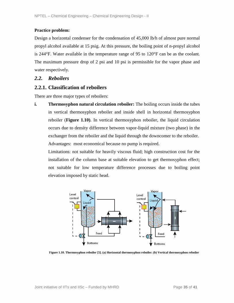
i. Thermosyphon natural circulation reboiler: The boiling occurs inside the tubes
in vertical thermosyphon reboiler and inside shell in horizontal thermosyphon
reboiler (Figure 1.10). In vertical thermosyphon reboiler, the liquid circulation
occurs due to density difference between vapor-liquid mixture (two phase) in the
exchanger from the reboiler and the liquid through the downcomer to the reboiler.
Advantages: most economical because no pump is required.
Limitations: not suitable for heavily viscous fluid; high construction cost for the
installation of the column base at suitable elevation to get thermosyphon effect;
not suitable for low temperature difference processes due to boiling point
elevation imposed by static head.
Figure 1.10. Thermosyphon reboiler [5]. (a) Horizontal thermosyphon reboiler. (b) Vertical thermosyphon reboiler
NPTEL – Chemical Engineering – Chemical Engineering Design - II
Joint initiative of IITs and IISc – Funded by MHRD Page 36 of 41
ii. Forced circulation reboiler: The liquid is fed by means of a pump. Forced
circulation reboilers with vertical or horizontal tubes boiling may be designed.
Forced circulation reboilers are similar to vertical thermosiphon reboilers, except
the pump is used for the circulation of the liquid and the hot liquid flows inside
column. To calculate the heat transfer coefficient it is generally assumed that, heat
is transferred only by forced convection. The usual method of shell and tube
exchanger design can be used.
Advantage: suitable for viscous and highly fouling fluids.
Disadvantage: high pumping and maintenance cost; pump is required to circulate
the boiling liquid through the tubes and back into the column.
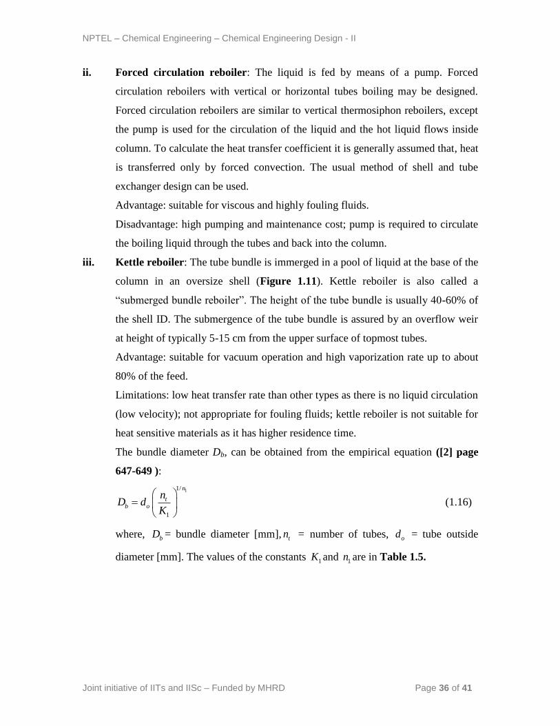
iii. Kettle reboiler: The tube bundle is immerged in a pool of liquid at the base of the
column in an oversize shell (Figure 1.11). Kettle reboiler is also called a
“submerged bundle reboiler”. The height of the tube bundle is usually 40-60% of
the shell ID. The submergence of the tube bundle is assured by an overflow weir
at height of typically 5-15 cm from the upper surface of topmost tubes.
Advantage: suitable for vacuum operation and high vaporization rate up to about
80% of the feed.
Limitations: low heat transfer rate than other types as there is no liquid circulation
(low velocity); not appropriate for fouling fluids; kettle reboiler is not suitable for
heat sensitive materials as it has higher residence time.
The bundle diameter Db, can be obtained from the empirical equation ([2] page
647-649 ):
11/
1
n
tb o
nD d
K
(1.16)
where, bD = bundle diameter [mm], tn = number of tubes, od = tube outside
diameter [mm]. The values of the constants 1K and 1n are in Table 1.5.
NPTEL – Chemical Engineering – Chemical Engineering Design - II
Joint initiative of IITs and IISc – Funded by MHRD Page 37 of 41
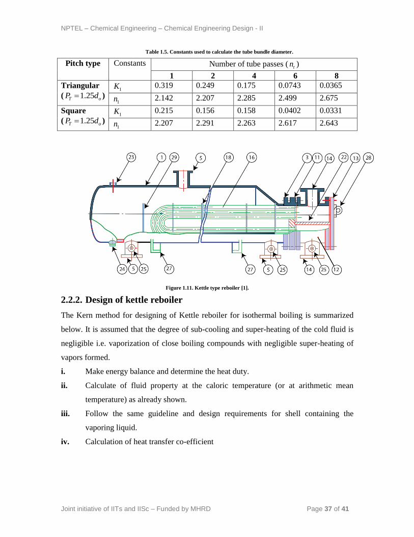
Table 1.5. Constants used to calculate the tube bundle diameter.
Pitch type Constants Number of tube passes ( tn )
1 2 4 6 8
Triangular
( 1.25T oP d ) 1K 0.319 0.249 0.175 0.0743 0.0365
1n 2.142 2.207 2.285 2.499 2.675
Square
( 1.25T oP d ) 1K 0.215 0.156 0.158 0.0402 0.0331
1n 2.207 2.291 2.263 2.617 2.643
Figure 1.11. Kettle type reboiler [1].
2.2.2. Design of kettle reboiler
The Kern method for designing of Kettle reboiler for isothermal boiling is summarized
below. It is assumed that the degree of sub-cooling and super-heating of the cold fluid is
negligible i.e. vaporization of close boiling compounds with negligible super-heating of
vapors formed.
i. Make energy balance and determine the heat duty.
ii. Calculate of fluid property at the caloric temperature (or at arithmetic mean
temperature) as already shown.
iii. Follow the same guideline and design requirements for shell containing the
vaporing liquid.
iv. Calculation of heat transfer co-efficient
NPTEL – Chemical Engineering – Chemical Engineering Design - II
Joint initiative of IITs and IISc – Funded by MHRD Page 38 of 41
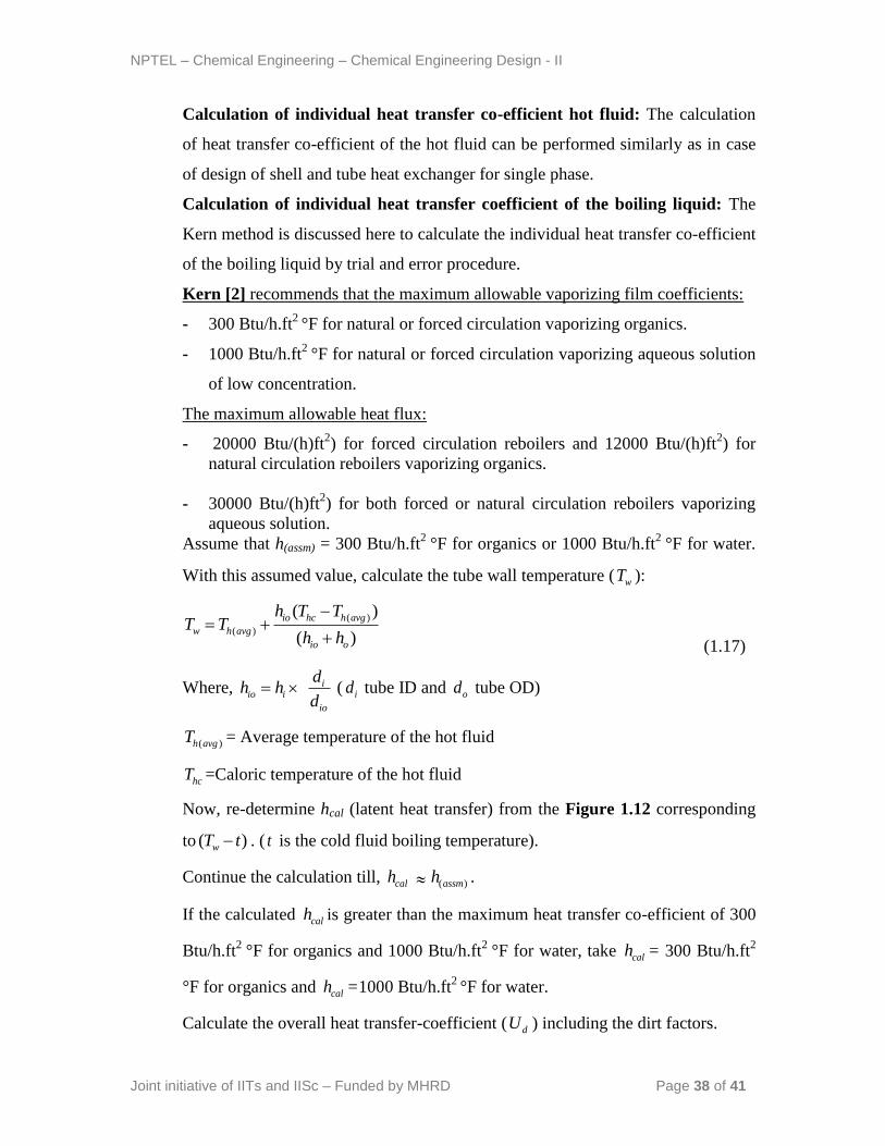
Calculation of individual heat transfer co-efficient hot fluid: The calculation
of heat transfer co-efficient of the hot fluid can be performed similarly as in case
of design of shell and tube heat exchanger for single phase.
Calculation of individual heat transfer coefficient of the boiling liquid: The
Kern method is discussed here to calculate the individual heat transfer co-efficient
of the boiling liquid by trial and error procedure.
Kern [2] recommends that the maximum allowable vaporizing film coefficients:
- 300 Btu/h.ft2
°F for natural or forced circulation vaporizing organics.
- 1000 Btu/h.ft2
°F for natural or forced circulation vaporizing aqueous solution
of low concentration.
The maximum allowable heat flux:
- 20000 Btu/(h)ft2) for forced circulation reboilers and 12000 Btu/(h)ft
2) for
natural circulation reboilers vaporizing organics.
- 30000 Btu/(h)ft2) for both forced or natural circulation reboilers vaporizing
aqueous solution.
Assume that h(assm) = 300 Btu/h.ft2
°F for organics or 1000 Btu/h.ft2
°F for water.
With this assumed value, calculate the tube wall temperature ( wT ):
( )
( )
( )
( )
io hc h avg
w h avg
io o
h T TT T
h h
(1.17)
Where, iio i
io
dh h
d ( id tube ID and od tube OD)
( )h avgT = Average temperature of the hot fluid
hcT =Caloric temperature of the hot fluid
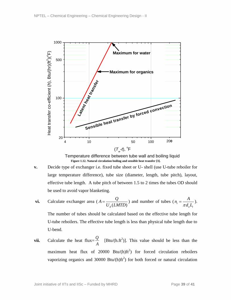
Now, re-determine hcal (latent heat transfer) from the Figure 1.12 corresponding
to ( )wT t . ( t is the cold fluid boiling temperature).
Continue the calculation till, calh ( )assmh .
If the calculated calh is greater than the maximum heat transfer co-efficient of 300
Btu/h.ft2
°F for organics and 1000 Btu/h.ft2
°F for water, take calh = 300 Btu/h.ft2
°F for organics and calh =1000 Btu/h.ft2
°F for water.
Calculate the overall heat transfer-coefficient ( dU ) including the dirt factors.
NPTEL – Chemical Engineering – Chemical Engineering Design - II
Joint initiative of IITs and IISc – Funded by MHRD Page 39 of 41
10 100
100
1000
He
at tr
an
sfe
r co
-effic
ien
t (h
), B
tu/(
hr)
(ft2
)(oF
)
(Tw-t),
oF
Temperature difference between tube wall and boiling liquid
Maximum for organics
Maximum for water
Sensible heat transfer by forced convection
Late
nt
heat
tran
sfe
r
204
500
50 200
Figure 1.12. Natural circulation boiling and sensible heat transfer [3].
v. Decide type of exchanger i.e. fixed tube sheet or U- shell (use U-tube reboiler for
large temperature difference), tube size (diameter, length, tube pitch), layout,
effective tube length. A tube pitch of between 1.5 to 2 times the tubes OD should
be used to avoid vapor blanketing.
vi. Calculate exchanger area (( )d
QA
U LMTD ) and number of tubes ( t
o t
An
d L ).
The number of tubes should be calculated based on the effective tube length for
U-tube reboilers. The effective tube length is less than physical tube length due to
U-bend.
vii. Calculate the heat flux=Q
A [Btu/(h.ft
2)]. This value should be less than the
maximum heat flux of 20000 Btu/(h)ft2) for forced circulation reboilers
vaporizing organics and 30000 Btu/(h)ft2) for both forced or natural circulation
NPTEL – Chemical Engineering – Chemical Engineering Design - II
Joint initiative of IITs and IISc – Funded by MHRD Page 40 of 41
reboilers vaporizing aqueous solution. Otherwise, go to step # v, repeat the
calculation until within the allowable limits.
viii. Check for allowable vapor velocity ( vu ) ([3] page 749):
The maximum vapor velocity vu (m/s) at the liquid surface should be less than
that given by the expression below to avoid too much entrainment.
1/ 2
0.2 l vv
v
u
(1.18)
where, l = liquid density and, l = vapor density
If this criterion is not satisfied, go to step # v and revise the calculation.
ix. Pressure drop calculation
Tube side pressure drop (hot fluid): The pressure drop calculation of the hot fluid
can be carried out as already presented.
Shell side pressure drop (vaporizing liquid): There will be negligible hydrostatic
head for the flow of liquid from the column to reboilers (low circulation velocity) if
the liquid level above the tube bundle is not too high. Therefore, shell side pressure
drop may be considered negligible.
x. Calculate over surface and over design
xi. Go for mechanical design
Design problem:
Gasoline (65°API gravity) flow rate of 60,000 lb/h with a small boiling range at 400°F is
to be vaporized to form 37,050 lb/h vapor at an operating pressure of 200 psig. Use gas
oil (30°API gravity) in the temperature range from 600 to 500°F at 120 psig operating
pressure as the heating medium. A tube side pressure drop of 10 psi is allowable. Design
a suitable Kettle reboiler to serve the purpose.
NPTEL – Chemical Engineering – Chemical Engineering Design - II
Joint initiative of IITs and IISc – Funded by MHRD Page 41 of 41
References
[1]. Indian Standard (IS: 4503-1967): Specification for Shell and Tube Type Heat
Exchangers, BIS 2007, New Delhi.
[2]. R. K. Sinnott, Coulson & Richardson‟s Chemical Engineering: Chemical
Engineering Design (volume 6), Butterworth-Heinemann, 3rd
ed. 1999.
[3]. D. Q. Kern, Process Heat Transfer, McGraw-Hill Book Company, Int. ed. 1965.
[4] Dutta B.K. „Heat Transfer-Principles and Applications‟, PHI Pvt. Ltd., New
Delhi, 1st ed. 2006.
[5] James R. Couper; W. Roy Penney, James R. Fair, Stanley M. Walas, Chemical
Process Equipment: selection and design, Elsevier Inc., 2nd
ed. 2005.